The Heathkit SB-401 Transmitter - Nostalgic Kits Central
The Heathkit SB-401 Transmitter - Nostalgic Kits Central
The Heathkit SB-401 Transmitter - Nostalgic Kits Central

You also want an ePaper? Increase the reach of your titles
YUMPU automatically turns print PDFs into web optimized ePapers that Google loves.
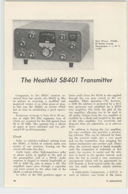
Mort Waters W2J Dl<br />
82 Boston Avenue<br />
Massapequa, l. I.. N. Y.<br />
11 758<br />
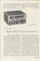
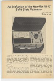
<strong>The</strong> <strong>Heathkit</strong> 58<strong>401</strong> <strong>Transmitter</strong><br />
Companion to the <strong>SB</strong>301 receiver reviewed<br />
here last month, the <strong>SB</strong><strong>401</strong> is, like<br />
its partner in receiving, a modified and<br />
improved version of an older piece of gear,<br />
in this case the <strong>SB</strong>400, an exciter which<br />
lost no time in establishing a good reputation.<br />
Frequency coverage is from 10 to 80 meters<br />
in eight 500 kHz segments, four of<br />
which are required for the full spread from<br />
28 to 30 Mllz. <strong>The</strong> operator has a choice<br />
of upper or lower sideband and vox activated<br />
C\V on all frequencies.<br />
C ircuit<br />
Make no mistake-nothing's missing from<br />
the S1l40I. A fistful of controls make you<br />
master of any situation. Tracing out the<br />
circuit will make this clear.<br />
Audio input, either high-impedance mike<br />
or phone patch, is applied to the grid of<br />
the preamplifier, half of a 6EA8. Audio<br />
response is shaped to restrict bandwidth to<br />
350 to 2450 Hz, plus or minus 3 dB. <strong>The</strong><br />
amplified signal goes through a capacitor<br />
and level control to the other half of the<br />
6EA8, a cathode follower.<br />
In either of the S<strong>SB</strong> positions-upper or<br />
98<br />
lower-audio from the 6EA8 is also applied<br />
through the vox gain control to the vox<br />
amplifier. When operating CW, however,<br />
a 1000 lIz sidetone is generated by a 6J11<br />
tone generator and amplified by a 6D IO<br />
tone amplifier; this feeds the grid of the<br />
vox amplifier, allowing vox to be used in<br />
all modes. Output from the vox amplifier is<br />
rectified by a diode and coupled to the grid<br />
of the relay amplifier. Vox sensitivity and<br />
drop-out time are adjustable, as is anti-vox<br />
level.<br />
In addition to keying the vox amplifier,<br />
the tone oscillator also provides a monitoring<br />
sidetone. This can be obtained by feeding<br />
the receiver audio into a rear panel<br />
jack on the transmitter, then plugging the<br />
station loudspeaker into another jack. <strong>The</strong>reafter,<br />
the received signal is heard normally<br />
until the transmitter is activated; at that<br />
point. the receiver is muted and the sidetone<br />
is heard in the speaker instead, each<br />
time the key is closed-a very convenient<br />
arrangement which will be appreciated by<br />
CW hounds. A level control inside the cabinet,<br />
but easily accessible, adjusts sidetone<br />
volume.<br />
A triple-triode Compactron, a 6AVII, is<br />
used as follows: one triode is the lower<br />
73 MAGAZINE
sideband carrier generator, at 3393.6 kHz.<br />
~ Another triode section is for the upper sideband<br />
carrier at 3396.4 kHz, and in the<br />
CW mode, uses another crystal at 3395.4<br />
kHz. Only that triode selected by the mode<br />
switch receives plate voltage. <strong>The</strong> third triode<br />
is a cathode follower in all modes.<br />
Audio from the speech-amplifier cathode<br />
follower and carrier from the sideband genera<br />
tor are fed to a diode ring balanced<br />
modulator whose output is the sum and<br />
difference of the audio and carrier frequencies.<br />
\Vhen operating on C\ V, a small<br />
de voltage upsets the balance of the modulator,<br />
producing output on the C\V carrier<br />
frequency.<br />
<strong>The</strong> signal is then coupled through a transfanner<br />
to the grid of a 6AV6. which isolates<br />
the balanced modulator from the crystal<br />
filter and provides for the proper impcdance<br />
matching. This stage is also partially<br />
controlled by ALC (automatic level<br />
control) voltage which will be mentioned<br />
later. From the isolation amplifier, the signal<br />
next goes to a 2.1 kHz crystal lattice filter,<br />
emerging to be coupled to the grid of the<br />
6E\V6 mixer.<br />
<strong>The</strong> <strong>SB</strong><strong>401</strong>'s VFO operates over a range<br />
of 5 to 5.5 mHz, its output passing to the<br />
cathode of the 6E\V6 mixer, which produces<br />
the sum and difference of the VFO<br />
and previously generated frequencies. <strong>The</strong><br />
sum frequency is then coupled through a<br />
bandpass coupler (8.395 to 8.895 MHz) to<br />
the grid of the heterodyne mixer. another<br />
6EW6.<br />
<strong>The</strong> triode portion of a 6A\V8 is a<br />
heterodyne oscillator whose plate voltage<br />
is regulated, and whose frequency is deten<br />
nined by one of the eight switch-selected<br />
crystals. Its output is also coupled to the<br />
grid of the 6EW6 heterodyne mixer. In<br />
passing, note that the sale function of the<br />
pentode section of the same 6A\V8 is to<br />
amplify the heterodyne oscillator input from<br />
the companion receiver, the 513301, when<br />
operating transceive. Only when the mode<br />
switch is in the "transceive" position is<br />
plate voltage applied to this part of the<br />
tube. In the "independent transmit" posiion,<br />
voltage is applied instead to the plate<br />
of the 6A\V8 heterodyne oscillator.<br />
<strong>The</strong> signals from th e bandpass coupler<br />
and heterodyne oscillator are mixed in the<br />
6EW6 heterodyne mixer. Only the difference<br />
frequencies reach the grid of the<br />
6CL6 driver tube. A trap in the driver grid<br />
suppresses a spurious signal at 8.6 MHz<br />
which might otherwise appear in the output<br />
on the 7 MHz band.<br />
Driver output is applied to the grids of<br />
a pair of 6146's in parallel, operating in<br />
Class ABI. An internal pot sets bias at -50<br />
volts to hold the no-signal plate current<br />
at 50 rnA.<br />
Peak driving voltage for the finals is<br />
variable with the C\ V level control, which<br />
is in tandem with the microphone gain on<br />
the front panel. In S<strong>SB</strong> operation, the limittug<br />
action of the ALe circuitry also affects<br />
the driving voltage.<br />
A conventional pi network couples final<br />
output to the antenna. Impedances of approximately<br />
40 to 150 ohms can be matched.<br />
A built-in relay automatically transfers the<br />
antenna from the transmitter to the receiver.<br />
Frequency CoveraKe:<br />
Emission :<br />
Input power:<br />
Out put power :<br />
Output impedance:<br />
F req uency sta bility:<br />
Sideband generation:<br />
Dial accuracy:<br />
Features :<br />
P ower requirements :<br />
Size and weight :<br />
P rice :<br />
8B-0I01 Specifications<br />
3.5 to 01.0; 7.0 to 7.5:<br />
14.0 to 101.5; 21.0 to 21.5;<br />
28.0 to 28.5; 28.5 to 29.0 :<br />
29.0 to 29.5 ; 29.5 to 30.0<br />
MHz.<br />
Selectable upper or lower<br />
sideband, CW o<br />
180 watta P EP 8<strong>SB</strong>, 170<br />
watta C W o<br />
100 watts on 80 throua-h<br />
15 meters ; 80 wa tts on<br />
on 10 meters.<br />
50 t o 75 ohms.<br />
Less than 100 H z d rift<br />
p er hour after 20 m inute<br />
wa rmup period. Less t han<br />
100 H z drift for 10%<br />
changes in line voltage.<br />
Crystal lattice filter . Car <br />
r ier suppression 55 dB<br />
down from rated output.<br />
Unwanted sideband suppression<br />
55 d B down f rom<br />
rated output at 1000 H :r.<br />
and h igher. Third or der<br />
distor tion 30 d B down<br />
f rom rated PEP ou tput.<br />
Visual accuracy w it h in<br />
200 H z on all bands :<br />
Electrical accur acy wit h <br />
in 01 00 H z on a ll bands<br />
a fter calibration to nearest<br />
100 kHz point.<br />
Noise level at Ieeet (0 dB<br />
below rated carrier ; audIo<br />
frequency response f rom<br />
350 to 2(50 H z ; 10 dB<br />
audio eompreeefon ; h igh<br />
impedance microphone a n d<br />
p hone-patch inputs.<br />
105-125 vee. 60/60 Hz. 80<br />
watts in stan dby; 260<br />
watts CW (key down).<br />
14 % " x 6%" x 13% " .<br />
26'h pounds.<br />
$285. (Op tion a l crystal<br />
pack $29.95).<br />
JULY 1967<br />
99
In either L<strong>SB</strong> or U<strong>SB</strong> modes, when the<br />
final tubes are driven into grid current, a<br />
voltage appears at the junction of a resistor<br />
and capacitor in the final grid circuit.<br />
This voltage, which follows the audio<br />
peaks. is rectified by a pair of diodes and<br />
appears on the grid of the 6AV6 isolation<br />
amplifier as a bias. Thus, should the finals<br />
be overdriven, gain is reduced immediately<br />
to prevent splatter. In one of its several<br />
switchable positions, the panel meter displays<br />
the ALe voltage. By keeping an eye<br />
cocked at it, drive may be effectively controlled<br />
by holding voice and gain at the<br />
level where the needle stays where it's supposed<br />
to.<br />
<strong>The</strong> meter also reads final grid and plate<br />
current and plate voltage, as well as relative<br />
output and is very useful in tuning up<br />
and operating within the proper parameters.<br />
<strong>The</strong> lineup is completed by a solid state<br />
power supply furnishing 720 volts de under<br />
full load of 250 mA. Lower voltage dc-250<br />
volts-is also provided for other stages, and<br />
there is -170 volts of bias too.<br />
Comparison with the 58400<br />
<strong>The</strong> major difference between the new<br />
rig and its rather young ancestor is «instant<br />
transceive". Owners of the <strong>SB</strong>400 will<br />
recognize the value of this new feature immediately;<br />
you no longer have to open the<br />
cabinet and change the output cable from<br />
the VFO to switch modes. It was never a<br />
hig deal to do so, but there's no doubt that<br />
the convenience is well worth having. So<br />
many <strong>SB</strong>400 owners have home-brewed conversions<br />
that will do the same thing that a<br />
number of articles have already found their<br />
way into the magazines.<br />
At least one unpubUcized<br />
version this writer knows of<br />
(K2UUJ fathered it) was based on the fact<br />
that the heterodyne oscillator is activated<br />
only in the transceive mode. <strong>The</strong> plate voltage<br />
was picked up at a convenient point<br />
to power a relay that performed the actual<br />
switching of cables. Other schemes have<br />
been used successfully.<br />
An added driver coil is an important but<br />
less noticeable improvement which results<br />
in more 10 meter drive. <strong>The</strong> single driver<br />
coil in the <strong>SB</strong>400 was tuned for 28 MHz.<br />
As a result, drive was insufficient in the<br />
upper reaches of the band. Now, with the<br />
extra coil peaked at 29 MHz switched into<br />
the circuit better results are assured.<br />
<strong>The</strong> VFO mixer stage, although still us-<br />
100<br />
ing a 6EW6, has been completely revamped.<br />
Even a casual comparison shows the difference<br />
at once. A 21.1 ~IHz trap is now<br />
included in the circuit. <strong>The</strong>re arc many<br />
minor revamps elsewhere, the mere fact of<br />
their existence is a pretty good indication<br />
that the boys at Benton Harber arc satisfied<br />
with nothing but the ultimate and continue<br />
to improve their product even when<br />
it is already well accepted.<br />
As further evidence of this thinking, the<br />
58<strong>401</strong> has a 680 ohm resistor inserted in<br />
the screen voltage supply to the finals. It<br />
has been added because it reduces the already<br />
acceptable distortion products figure<br />
by 3 to 4 dB more.<br />
Although the <strong>SB</strong>400 was designed to operate<br />
independently or transceive with the<br />
<strong>SB</strong>300 receiver (which it will also do with<br />
the new <strong>SB</strong>301 ), it was sold only as a complete<br />
unit. With the advent of the <strong>SB</strong><strong>401</strong>,<br />
however, Heath has changed their marketing<br />
strategy and made the rig even more<br />
of a bargain for those who own the receiver.<br />
<strong>The</strong> new model is available complete, as<br />
before-which is what you'd need to use<br />
it with any other receiver-but, if you own<br />
either the <strong>SB</strong>300 or <strong>SB</strong>301, you can buy<br />
the transmitter for less without the crystals<br />
which are sold as a separate accessory.<br />
<strong>The</strong> new transmitter's VFO has been modified,<br />
just as it was in the transition from<br />
one receiver to another. Minor circuitry<br />
changes and use of an industrial type 6BZ6<br />
instead of the old 6AU6 is the story. At<br />
the risk of boring those who may have read<br />
the review of the <strong>SB</strong>301, this seems to be<br />
gilding the lily, because the original VFO<br />
was rock steady. <strong>The</strong> new one is<br />
at least<br />
as good, if not better.<br />
Other minor but noticeable changes . . .<br />
a different type of socket on the rear panel<br />
to provide line voltage ac to operate external<br />
relays; the use of two terminal boards<br />
smaller than used in the <strong>SB</strong>400 for below<br />
chassis parts mounting, cleaning things up<br />
nicely.<br />
Construction, alignment and operation<br />
A total of 37); hours was spent building<br />
the transmitter, including about two hours<br />
for photography. Alignment, for which you<br />
need a VTVM with an rf probe, a ham<br />
band or general coverage receiver, and a<br />
dummy load, took about 3 hours more.<br />
Would-be builders may benefit from these<br />
suggestions:<br />
73 MAGAZINE
Before soldering any connections from the<br />
cable harnesses, lay them in the most advantageous<br />
position. T wisting them here and<br />
there will make for a neater job. Take this<br />
precaution- where the manual specifically<br />
instructs you not to shorten leads breaking<br />
out of the harness, don't. Hear and obey!<br />
Make every effort to achieve proper alignment<br />
of th e dial mechanism. Set up right<br />
it is as smooth as the expensive spread;<br />
if not, it shrieks, groans and otherwise<br />
suffers.<br />
Once construction, alignment and calibration<br />
arc finished, you can begin to enjoy<br />
th e fruits of your labor. This transmitter<br />
is everything you could want. S<strong>SB</strong> buffs<br />
will be proud of their clean, splatter-free<br />
signals, excellent suppression, freedom from<br />
drift, and natural audio quality. <strong>The</strong> vox<br />
is smooth and can be adjusted from instant<br />
dropout to holding in long enough so that<br />
you'll never kn ow you worked Don Miller.<br />
This is no gag-I found m yself cuttin g its<br />
hold-in time for fear I wouldn't hear his<br />
rapid-fire comebacks.<br />
Brasspounders will revel in the clean,<br />
chirp free T9X note, to say nothing of the<br />
convenience of the built-in sidetone and voxactivated<br />
b reak-in keying. <strong>The</strong> scope in m y<br />
shack displays a sillJ1al which is shaped good,<br />
like a CW signal should.<br />
Add the undeniably good looks of the p ackage,<br />
the fractional kHz readout, and you've<br />
got quite a piece of equipment.<br />
Final comments concern transceive operation<br />
with the S8300 or <strong>SB</strong>301. Numerous<br />
interconnecting cables are required, as expected,<br />
but three of them-those which bring<br />
the VFO, BFO and heterodyne oscillator signals<br />
into the transmitter-must be cut from<br />
RG62 coax cable to exactly 2 feet. <strong>The</strong> cable<br />
is supplied with the kit.<br />
When the transmitter and receiver are<br />
interconnected and CW operation is desired,<br />
the transmitter's mode switch should remain<br />
in the "transceive" position at all times,<br />
whether actually transceiving or operating<br />
split frequency. If the mode switch is set<br />
instead to the "transmit" position for C\V,<br />
a constant beat note is heard in the receiver.<br />
This isn't too clear in the manual and it<br />
took a personal discussion with the H eath<br />
engineers before it was cleared up. As a<br />
result, they have issued a bulletin to clarify<br />
the matter, and arc including a revision in<br />
current production. This also applies to the<br />
<strong>SB</strong>300 /400 combination. . .. W2JDL<br />
JULY 1967<br />
•<br />
VANGUARD<br />
MODEL 501<br />
Made In USA.<br />
$279.95<br />
SHIPPING COllECT<br />
COMPLETE WITH LENS<br />
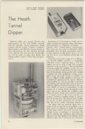
SUB·MINIATURE SOLID STATE<br />
TV CAMERA<br />
FOR CLOSED CIRCUIT OR AMATEUR TV<br />
THE VANGUARD 501 Is a completely automatIc<br />
closed circuit television camera capable of transmitting<br />
aharp, clear, live pictures to-one or more TV sets<br />
of your choice vIa a low-cost antenna cable (RG·59U)<br />
up to a distance of 1000 ft without the need for ecceasorle.<br />
or modifications on the TV sets. <strong>The</strong> range<br />
can be extended Indefinitely by using line amplifiers<br />
at repeated Intervals or by using radio transmitters<br />
where regulatron.. permit. -<br />
<strong>The</strong>re are hundreds of practical uses tn business,<br />
hom e, school, etc. for eny purpose that requires you<br />
or a nyone chosen to observe anything taking place<br />
anywhere the camera Is placed. Oe51gned for continuous<br />
unattended operat ion, the ali-transistor circuitry<br />
of the 501 consumes only 7 watts of power.<br />
SPECIFICATIONS:<br />
• MlliurlS 2¥t" x 4" x 7" (excluding rlns Ind connldon).<br />
• Wli.hs 3V1 Ibs.<br />
• Opwltes on 100_130 yoltl 50 or 60 cyclls, 7 Wltft.<br />
• Tested at 10° to 125" F.<br />
• Adyanced circuitry utilizing 35 Ilml-eondudon most of<br />
which .rl IlIicon.<br />
• filld Iffect input circuit for mTnJmvm video noise.<br />
• Resolution guar.nteed to exceed standardl lIt by 515<br />
line TV rlcelYlfl.<br />
• Rf output 30.000 microyolts adjustable for channe'. 2<br />
to 6. .<br />
• Video output 1.5V Pop composi'e with sfandard nlg..<br />
tiYI sync (r. ndom interllce).<br />
• Vlew.ble pictures obt.in.bla with iIIumin.tTon IS low<br />
as 1 ft. cendll.<br />
• Vidicon controlled light companlltion; 150/1.<br />
• Adju.t.bll iris on Ilnl In.bl., u.e in bright sunlight.<br />
• NIW long life, sull_minleture vidicon with spectraT response<br />
slmller to Type n35A.<br />
• flectroniClI:T regulatld power supply and thermlllly<br />
compenllte circuits elimlnll'e chanSie In picture qUllity<br />
when line voltllSie and temperature fluctuate.<br />
• All Pllrts ,u.r.nteed for 1 year (except for open fil.·<br />
ment on Vidicon or braakilgl).<br />
• ,,,,t, low-cost service .lwilY' available from our f.ctory<br />
in Hollis, N.Y.<br />
Pre-set AdJ ust.b1e eontrols Inelud. the followln.: Video • •In,<br />
vide. COmPenSlltl on, pld est.1 level. tll.et \lolt.,e. beam \lolt••••<br />
bu m al iGnment. ellotrleal foeUl, horizontal freQuency. horluntal<br />
slu , n rU eal f"Quancy. ve rtloal lilt, vertloal linearity, modula.<br />
tion and RF frequency out put.<br />
Send your o,der dired 10 our faclory<br />
VANGUARD LABS<br />
196.!S Jamai.. Ave. Dept. S Hollis, N.Y. 11423