The Heath HX-30 - Nostalgic Kits Central
The Heath HX-30 - Nostalgic Kits Central
The Heath HX-30 - Nostalgic Kits Central

You also want an ePaper? Increase the reach of your titles
YUMPU automatically turns print PDFs into web optimized ePapers that Google loves.
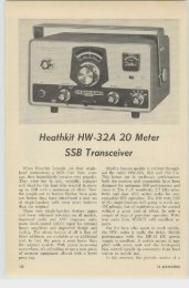
<strong>Heath</strong> 6M<br />
SSB Transmitter<br />
Kent Mi tche ll W3WTO<br />
Almost every metropolitan area of the ginning right at the m ike input, let's follow<br />
United States h as experienced a boom in 6 the audio through the rig until it emerges from<br />
meter activity during recent years ... due in the antenna coax jack as a single sideband rf<br />
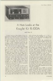
no small respect to <strong>Heath</strong>'s introduction of signal. <strong>The</strong> heart of the rig is the balan ced<br />
their now famous 5 watt power house, the modulator shown in Fig. 2. A speech amplifier<br />
"Stxer.' <strong>The</strong>n too, and especially during band not only boosts the mike input, but attenuates<br />
openings, quite a few of the boys may be the audio frequencies below <strong>30</strong>0 cps and above<br />
heard modulating a <strong>Heath</strong> 120 watt «Seneca." <strong>30</strong>00 cps, which experience has shown to be<br />
Ind eed , OUf most popular VHF band might the only really necessary range for good voice<br />
sound altogether different without <strong>Heath</strong>kits. intelligibility. <strong>The</strong> audio is now split into two<br />
Now however, 6 meters is going to sound dif- equal, but 90 degree out of phase signals by<br />
ferent with <strong>Heath</strong>kits . .. namely the <strong>HX</strong>-<strong>30</strong>. an aud io phase shift network. Amplified by<br />
T his new SSB transmitter is going to become V3A and V3B, these voltages are applied to<br />
as popular as sliced bread!<br />
the grids of balanced modulators V4 and V,5.<br />
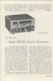
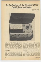
A complete, self-contained unit (not a An rf carrier is generated at 11.5 mc by a<br />
"transverter"}, the <strong>HX</strong>·<strong>30</strong> offers a frequency crystal controlled oscillator V2B and also apcoverage<br />
of 50 ,0 to 54.0 megacycles in four, plied to the grids of the balan ced modulators<br />
1 megacycle steps, an ultrastable fine tuning after it too has been split into two 90 degree<br />
VFO, and excellent on-the-air audio character- out of phase signals. So now, at the grids of<br />
istics with unwanted sideband suppression on V4 and V5 we h ave two separate carriers bethe<br />
order of 40 db. Carrier suppression is 50 ing combined with modulation. Here is where<br />
db below maximum rf outp ut.<br />
we eliminate the carrier and produce the de-<br />
Provid ing 10 watts peak envelope power sired single sideband signal. Both balan ced<br />
output SSB, 10 walls of CW, and 2.5 walls modulators, consisting of two triodes each,<br />
with AM , the rig m ay be used as an exciter for V4A, V4B and V5A, V5B, each have their<br />
a linear amplifier (such as <strong>Heath</strong>'s HA-20, to grids connected in parallel for rf, and in pushbe<br />
featured in a later article) , or run "bare- pull for audio through. <strong>The</strong> plates of each<br />
foot" with excellent results.<br />
balanced modulator are connected in push-pull<br />
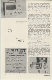
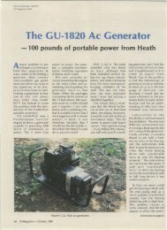
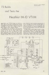
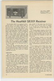
<strong>The</strong> single sideband signal is generated in through a common tank circuit and are 180<br />
this transmiller by the phasing method. Be- degrees ou t of phase with each other. <strong>The</strong><br />
V4<br />
BALANCED<br />
~ :l A u MODULATOR<br />
SPEECf AUDIO~ ODULAT OR<br />
T<br />
CARRIER RF PHASE BALANCED 11. 5 me<br />
PHASE<br />
SHIFT OSCILLATQ! SHI FT M ODULATOR<br />
TANK<br />
V'B<br />
l vox aJRE"LAy l M ODULATOR I V5<br />
BALANCED<br />
~ I MOCULATOR<br />
;<br />
II~ MC 42,4SMC SO-S4MC<br />
1/2 V9<br />
V6A V7 I V6 FINAL<br />
1st MIXER 2nd MIXER DRIVER<br />
50.0-54.5 Me<br />
8-9MC<br />
HETERODYNE<br />
OSCILLATOR tyFO ,~ CRYST A L<br />
OSCI L LATOR<br />
1/2 V9<br />
FINAL<br />
R F OUT<br />
SO-S4 MC<br />
FIGURE I<br />
<strong>HX</strong>-<strong>30</strong> BLOCK DIAGRAM<br />
112 73 MAGAZINE
HEWLETT·PACKARD<br />
400 D YTYM's<br />
New . . . . . . . . . . . . . . . $135<br />
Read·N·Save<br />
Pl 258 double female connector . . . . . $.70<br />
DB Meters 31h" rd-l0 to + 6db I mw @ 600 ohms $275<br />
Sperf Vacuum Switc hes for ART.13, etc. NEW $1.00<br />
Velv et Verniers w I large knob NEW $1.00<br />
600 Ohm <strong>30</strong>0 Watt No n- inductive Resistors . , . . . . $2.50<br />
WE·255A Polar Relays for TTP . . . $4. 50<br />
Soc kets for use with above relay ... . . . NEW $2.50<br />
Ohmite Z 28 rf Chokes 3 / 1.00<br />
Ohmite Z 144 rf Chokes , . ...4 / 1.00<br />
leach Relay #1351 110 vac spst . 2.00<br />
Pl ·259 or SO·239 coax conn . . . .3 / 1.00<br />
2C39A<br />
3CX lOOA5<br />
6 161<br />
829B<br />
4·65A . ..<br />
NEW SURPLUS TUBES GUARANTEED<br />
$7.50 8005 ... $14.00<br />
$10.00 4·250A . $21.00<br />
$35. 00 588 1 . . .. $1.50<br />
58.50 4-125A .. $20.00<br />
$7.50<br />
250TH<br />
4X250f<br />
807 .....<br />
6AN5 .. .<br />
$18.50<br />
$25.00<br />
$1.00<br />
$1.25<br />
We buy & sell large quantities of Military and Commercial<br />
Test Equipment. AN/GRC. PRC. TRC and test<br />
equipment TS and AN / UPM or URM. What have you<br />
for sal e or trade?<br />
TI S A RC.S X mrr, 2. 1· 3 me HRA XD XEW<br />
or ig inal sealed cartons $9 .95<br />
6 146 Tu~. new<br />
Tested and Guaranteed $2.25 ea, 2 1$4.00<br />
R G · l 1AfU Coax Cable (72 ohm)<br />
100 ft roll w 1'1.·259 ea end<br />
B erkeley ~t od el 5500C U niversal 100 ke<br />
cou nter & t imer L ab tested-perfect<br />
$7.50<br />
$425.00<br />
B C-46J A Transmitter and A M ),[odulators<br />
co nverts to 6 mtrs. uses 8 15 fin al 2 ea<br />
6L 6 Modulators-new w / t ubes $1 9.50<br />
Coax Relays S P J T 28vdc<br />
General Commu ni cations J N I2QRC or<br />
T hompson P roducts 10 566. New $17.95<br />
T -179 /AR T -26 T ran sm itt er s <strong>30</strong>0-600 mc. 35w<br />
B rand n ew "" ftubes. for ham T V $59.50<br />
$12.95<br />
-MONEY BACK GUARANTEE ON<br />
ANYTHING WE SELL<br />
ALL SHIPMENTS F.O.B. BRONX, N. Y .<br />
SPACE<br />
ELECTRONICS CO.<br />
218 West Tremont Ave., Bronx 53, N. Y.<br />
TRemont 8~5222<br />
product of all these phase relationships results<br />
in the carrier being balanced out and four<br />
sidebands containing the audio, with two inphase<br />
sidebands combining and two out of<br />
phase sidebands canceling .. . leaving only<br />
a single sideband signal. A more detailed explanation<br />
of how this phasing occurs may be<br />
found in several good texts available, such as<br />
the Single Sideband Com munications Handbook.<br />
Howard W . Sams and Co., Inc. (S6.9.5<br />
from Rud ie Bookshop) . T wo CARRIER BAL<br />
Ai\'CE cnntrols on the front panel of the <strong>HX</strong><br />
<strong>30</strong> are pots in the cathode circuits of the balanced<br />
modulators and enable their output voltages<br />
to be adjusted for equal amplitude.<br />
Transition from upper sideband to lower<br />
sideband, and vice versa, is performed simply<br />
by reversing the phase of the aud io signals on<br />
the grids of the balanced modulators. Placing<br />
the 1\IODE switch to the A~I position removes<br />
the aud io from the grids of V.5, unbalances<br />
V4A and V4E, thereby reinserting the carrier<br />
in the output at T4 and combining it with two<br />
out of phase sidebands. , , or in other words.<br />
g i v i n~ us a conventional A~ I signal. <strong>The</strong> C\ V<br />
mode is produced in a likewise manner, w ith<br />
the exception of removal of aud io from both<br />
the balanced modulators,<br />
So, we now have a SSE rf signal at 11.5<br />
me, a long way from 6 meters, but from here<br />
LAFAYETTE RADIO ELECTRONICS<br />
ASSOCIATE STORE<br />
6<strong>30</strong>6 Bea(h Blvd., Buena Park, Calif.<br />
See t he new l a fa yette and Ha llitrafters Tra ns: eivers!<br />
Plus Hommorlund, Hy Coi n. c esce an d othe rs<br />
Phone (7 14 ) S22-1193 73 d e G eorg ~ D :lYb W6SJ<br />
NUVISTORS rep eat of se ll-out . New Shipment.<br />
8RA ND NEW. RCA bulk pocked<br />
6CW4 or 6DS4, choice, postpaid, 3 for . . $5.25<br />
close ou t. ZCW4 , postpa id, 3 for . .. . $4.25<br />
Sockets for a ny cbove, with order. 3 for . . . . .50<br />
TUBES<br />
For followi ng, please add suff icient to cover postage<br />
& insurance. For Illinois de livery cdd 4% to cover<br />
soles tax,<br />
1625* tubes, SYLVA NIA {5 tbs.t, or N . U. (3 Lbs.t<br />
minimum moil c-oer 12 tubes for $2.00<br />
6DQ5 $1.75; 6DQ6B $ 1.00; 161 6· $1.00; 6 146 $3.00;<br />
807 $1.00; 3B28 $3.25; 5AW4 $.79; 5R4CY $.89<br />
QBRAN D NEW , others "pull-ouh" h om new sets.<br />
A ll are fully g uara nteed. No se co nds or reieeh.<br />
GOODIE SHEET h ee with every order<br />
SAV E YOUR lOOT! I' ll have a wag c>n teed of<br />
GOODI ES at the Montgomery, Ala . homfo:r Sunday,<br />
Apr. 21.<br />
BC<br />
ELECTRONICS<br />
2333 S. MICH IGAN AVE.<br />
CH ICAGO 16, ILL. CAl umet 5-2235<br />
APRIL 1963 113
•<br />
•<br />
mind. Rapid assembly is made possible by the<br />
use of four heavy duty etched circuit boards<br />
and three precut and laced wiring harnesses.<br />
Obviously, a great deal of forethought and<br />
planning went into this transmitter, both<br />
Fig. 2<br />
on out the rest is easy. <strong>The</strong> 11.5 me signal is<br />
coupled to the pentode section of a 6U8 tube<br />
operating as a mixer, where it is heterodyned<br />
with the output of a crystal controlled oscillator,<br />
the triode section of the 6U8. When the<br />
oscillator crystal frequency is <strong>30</strong>.5 me, the output<br />
of the mixer is 42 me. When this 42 me<br />
signal is heterodyned in the second mixer, a<br />
6CB6 (V7), with the output from the VFO or<br />
an 8 to 9 me crystal, we will have a 6 meter<br />
Fig. 3<br />
signal, between 50 and 5 1 me. Other 1 me<br />
segments of the band may be covered by<br />
changing the first oscillator crystal to the approp<br />
riate frequency. A 3 L~ crystal will cover<br />
51 to 52 me, a 32.5 me crystal will cover 52<br />
to 53 me, an d a 33.5 crystal will provide an<br />
output between 53 and 54 mc. Output of the<br />
second mixer is coupled to a 6AK6 d river ampli6er<br />
(V8) and then to the 6360 final amplifier,<br />
operating as a push-pull Class ABI amplifier.<br />
Link coupling is employed from the<br />
final to the rf ou tput jack.<br />
Assembly of the IlX-<strong>30</strong> is a pleasant and<br />
satisfying task. easily accomplished within the<br />
<strong>30</strong> hours mentioned in the <strong>Heath</strong> ads. Actually,<br />
I required 29 hours, in spite of the fact that<br />
I was taking notes and photographs as construction<br />
progressed, having this article in<br />
•<br />
Fig. 4<br />
mechanically and electrically. To cite one example,<br />
the tubes and circuit components are<br />
located on opposite sides of the etched circuit<br />
boards. \Vhen the boards are mounted, the<br />
tubes protrude upward through the chassis,<br />
thereby isolating the components from tube<br />
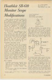
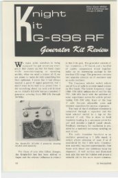
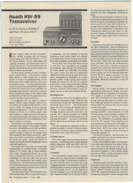
heat. Another example along the same lines<br />
is the complete isolation of the VFO tank<br />
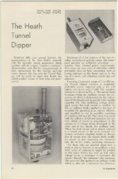
circuit from other circuits. Fig. 3 shows the<br />
interior of the VFO tank compartment, prior<br />
to its complete shielding. On the right is the<br />
VFO frequency capacitor. to the left are a<br />
bandspread trimmer and a temperature compensating<br />
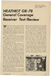
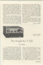
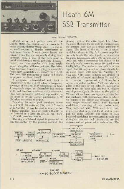
capacitor. Fig. 4 is a close-up of the<br />
VFO circuit board. Note the two crystal<br />
sockets which are for optional crystal control,<br />
utilizing the triode section of the 6CH8 VFO<br />
as a Colpitts oscillator. Figure 5 shows the<br />
completed VFO assembly. <strong>The</strong> large fin e<br />
toothed gear visible in the background is a<br />
portion of the VFO gear drive assembly. Providing<br />
exceptionally smooth VFO tuning, the<br />
helical gears give a ratio of approximately 45<br />
kc per tum of the spinner knob. Nine inches<br />
on the slide rule type dial equals only one<br />
megacycle of the 6 meter band! Compare that<br />
to your present 6 meter VFO or receiver dial.<br />
Alignment of the completed kit is simple<br />
and requires a minimum of time and eHort. An<br />
unusual feature is the use of test point jacks<br />
and a test probe connected to the front panel<br />
meter for alignment. <strong>The</strong> meter is then normally<br />
used as a rf power output indicator and<br />
to nun out the carrier. <strong>The</strong> initial adjustment<br />
of the audio phase and amplitude controls require<br />
an oscilloscope for optimum suppression<br />
of the unwanted sideband, but once set need<br />
no fu rther attention.<br />
Other features of the <strong>HX</strong>-<strong>30</strong> well worth<br />
mentioning include complete shielding of the<br />
114 73 MAGAZINE
SPECIAL<br />
100 kc Crystal Osc. Unit complete with<br />
crystal & oven thermostaticall y COntrolled<br />
. .00 0 15% accuracy or better.<br />
Un it #' 1 (Z 2001) of SRT 14 transmitter<br />
(see article "A Precision Freq. Sta ndard<br />
" Feb. 63, 73 page 88)<br />
BRAND NEW in orig ina l boxes<br />
schema t ic included<br />
Unit 1 with tubes (2-5814,<br />
1-5654) . .. .<br />
Unit 1 less tubes<br />
Unit 8 I SRTl 41 .<br />
Unit 9 I SRT I 41 .<br />
$24.75 pp<br />
22,75 pp<br />
OTHER SPECIALS<br />
$ 6.00 pp<br />
6.0 0 pp<br />
Unit l lA ISRT 141<br />
Unit 11 B I SRT I41<br />
$ 3.00<br />
6 .00<br />
15 me if cons-quality-curren t a ircraft type--New set o f 4 . . . . . . . .. . .. ..<br />
Collins 455 kc if- with three selectivity positions (2, 4, Ske) New ,., .<br />
ARCS/ command receivers---guoranteed opera ting cond., fo ir phys. cond o 6-9.1 mc .<br />
R4A I ARR2 rece iver-New . .. . . .. . .<br />
A lignment tool k it- 9 piece---New , .<br />
Coll ins 20 watt modulation transfo rmers (TCS type) New .<br />
Ch ~c k<br />
o r money orde r wit h o rde r, please<br />
RITCO ELECTRONICS BOX 156, ANNANDALE,<br />
See p . 44.<br />
up Feb., '62<br />
pp 73<br />
3.50 pp<br />
US5 ea.<br />
11.50<br />
4.50 p p<br />
1.25 p p<br />
2.35 eo. pp<br />
VA.<br />
final tank assembly, copper plated cabinet interior,<br />
built in VOX and anti-trip circuitry,<br />
and grid block keying along with a key click<br />
filter for clean CW signals. Although the rig<br />
was basically designed for SSB operation, it<br />
will produce good signals with other modes of<br />
transmission . .. no skimping was done here.<br />
Also, all <strong>Heath</strong>kits now include a suffi cient<br />
supply of multi-core solder at no extra cost.<br />
Another pleasant surprise was the inclusion of<br />
five free log books and a fine simulated leather<br />
vinyl cover.<br />
On the air tests resulted in reports of ex-<br />
Fig. 5<br />
cellent audio quality, no trace of carrier and<br />
very good suppression of the unwanted sidehand.<br />
Several QSO's were made with stations<br />
75 miles over the Blue Ridge mountains, quite<br />
a haul for only 10 watts on 6 meter ground<br />
wave, and a feat that is hard to duplicate with<br />
a lot more watts of AM from this QTH. Needless<br />
to say, sideband really gets through.<br />
Even as I was testing my own <strong>HX</strong>-<strong>30</strong>, I<br />
heard several other local stations using them<br />
on the band. Haven't you ordered your <strong>HX</strong>-<strong>30</strong><br />
yet? See you on 6 meter sideband!<br />
.. . W3WTO<br />
S PECIFI C AT I O NS<br />
F r equency CQverage--50.0 to 54.0 megacycles in fou r,<br />
I m~acy cle segment s. V F O or crystal cont rol.<br />
E mission- 5 SB, selectable upper or lower sideband . AM<br />
(inserted carrier w ith lo w level, amplitude modulation)<br />
.<br />
R F P ow er Output - 5 S B ( P .E. P.) 10 watts<br />
AM 2.5 watts<br />
CW 10 watts<br />
Carrier Suppression- 50db or more below maximu m ou tput.<br />
Unwanted Sideband Suppression- 40db or more below<br />
maximu m ou tpu t at 1000 cps inpu t.<br />
D istortion P roducte-c-Sndb or mor e below maximum output<br />
at 1000 cps input .<br />
H u m and N otse-c-audb or more below m aximum output.<br />
O utput Impedance--50 to 75 ohms u nbalanced.<br />
Crystals- U .S Carrier oscil1ator (furnished) <strong>30</strong>.5 F irst<br />
heterodyne oscillator (furnighed).t,. providing operat<br />
ion between 50. 0 to 51.0 me. Crystals for h igher<br />
band operation are not supplied.<br />
Audio F requency R esponse--<strong>30</strong>0 to <strong>30</strong>00 cps.<br />
Keyin g- Gr id block k eying with key click filter.<br />
V FO Tunin, K nob Ratio--A pproximately 45 kc per tum.<br />
P ower Requirements-e-Ll Z VAC 60 cps @ 95 watts.<br />
D imensions- 16% " wide, 10}i" high, 10" deep.<br />
W eigh t-40 pounds.<br />
Price--$189.9S<br />
APRIL 1963 115