The Eico 720 on Six Meters - Nostalgic Kits Central
The Eico 720 on Six Meters - Nostalgic Kits Central
The Eico 720 on Six Meters - Nostalgic Kits Central

You also want an ePaper? Increase the reach of your titles
YUMPU automatically turns print PDFs into web optimized ePapers that Google loves.
Ị -- - - - - - - - - - - - - - - - - - - - - - .<br />
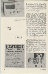
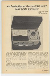
Saturn 6 Antenna <strong>on</strong>ly .. .$11.95<br />
Saturn 6 plus mast &<br />
bumper mount $16.95<br />
•<br />
SATURN 6<br />
the original<br />
HALO<br />
those designed for VHF work as most of the<br />
types used <strong>on</strong> the lower frequencies perform<br />
miserably in the VHF range. This applies more<br />
to transmitting tubes than receiving tubes.<br />
Coils should he air-wound if possible and<br />
wound with bare wire. A good grade of coil<br />
dope. such as GC "Q Dope," should be used<br />
if any is going to be used at all. Slug tuned<br />
coils should have slugs designed. to work at<br />
th e frequency at which the coils are being<br />
used. <str<strong>on</strong>g>The</str<strong>on</strong>g> type of slugs used <strong>on</strong> the broadcast<br />
bands and below 30 me are completely unsuitable<br />
for VHF work. Brass slugs decrease<br />
the inductance of the coil and are usually used<br />
at 2 meters and above as it makes the coil<br />
easier to wind. Stray inductance in leads<br />
should be avoided. VHF gear usually does<br />
not look neat because some of the neat wiring<br />
in which pa rts are parallel and at right angles<br />
to each other requires extremely l<strong>on</strong>g leads<br />
which make that type of wiring unsuitable<br />
for VHF.<br />
<str<strong>on</strong>g>The</str<strong>on</strong>g>se are the most comm<strong>on</strong> pitfalls to be<br />
avoided in VHF work. <str<strong>on</strong>g>The</str<strong>on</strong>g>re are many more,<br />
but these are the main <strong>on</strong>es. If a rig is built<br />
using this as a guide, very little trouble should<br />
be encountered with getting successful results.<br />
. .. WA2INM<br />
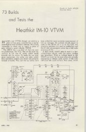
L<strong>on</strong>g John<br />
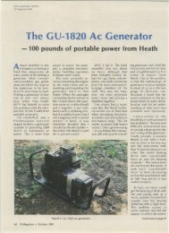
for <strong>Six</strong> <strong>Meters</strong> .<br />
FUTURES<br />
D••ig ned for mallimum forward gain.<br />
Gammo Match fOf cooax f••d.r.<br />
Fin• •t grade aluminum lubint' .<br />
Excepti<strong>on</strong>ally s' r<strong>on</strong>g l ine. there cue no drill ed<br />
hoi• •.<br />
All aluminum c<strong>on</strong>structi<strong>on</strong> e liminat•• e lectrolysi•.<br />
Entire beam Clnd support, c<strong>on</strong> b. g founded for<br />
lightning protecti<strong>on</strong>.<br />
w. are proud of ,his new l<strong>on</strong>g John Ante<strong>on</strong>o. W.'ve<br />
tried to put in every fea.ur. YOu could w<strong>on</strong>t. <str<strong>on</strong>g>The</str<strong>on</strong>g> r.<br />
sult i. II ,eol<strong>on</strong>obl. COl' high gain beam which can<br />
easily b. put up Gnd which will doy lhere practically<br />
forever. It has a wid. enough lo~ 10 you d<strong>on</strong>', have<br />
to Iwinv It a round all th. time, yet gives you tr.<br />
mendou. goin where you want it.<br />
Air Y OUR DIST RIBUT O RS OR F lU TE DIRECT<br />
HI-PAR<br />
Products CO.<br />
FITCHBURG, MASSACHUSETTS<br />
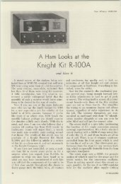
Putti ng the<br />
<str<strong>on</strong>g>Eico</str<strong>on</strong>g> <str<strong>on</strong>g>720</str<strong>on</strong>g><br />
<strong>on</strong> Si x <strong>Meters</strong><br />
Jomes Beckett WA2KTJ<br />
344 Po rk Aven ue<br />
C orning. New York<br />
N<br />
o doubt there are many of these fine<br />
. transmitters being used by Novices and<br />
Generals. So, in case you went from Novice<br />
to Technician or would just plain like to ge t<br />
a ll six without too much effort, this additi<strong>on</strong><br />
to the <str<strong>on</strong>g>720</str<strong>on</strong>g> will do th e trick.<br />
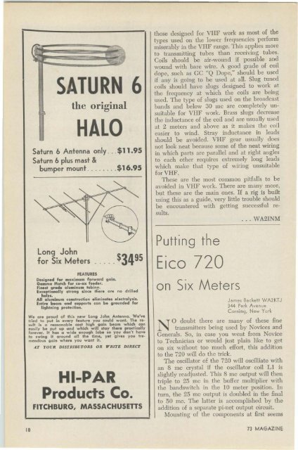
<str<strong>on</strong>g>The</str<strong>on</strong>g> oscillator of the <str<strong>on</strong>g>720</str<strong>on</strong>g> will oscilliate with<br />
an 8 mc crystal if the oscillator coil Ll is<br />
slightly readjusted. This 8 me output will then<br />
triple to 25 me in the buffer multiplier with<br />
the bandswitch in the 10 meter positi<strong>on</strong>. In<br />
tum, the 25 mc output is doubled in the fin al<br />
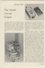
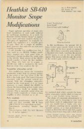
to 50 me. <str<strong>on</strong>g>The</str<strong>on</strong>g> latter is accomplished by the<br />
additi<strong>on</strong> of a separate pi-net output circuit.<br />
Mounting of the comp<strong>on</strong>ents at first seems<br />
18 73 MAGAZINE
v a<br />
•<br />
..;.<br />
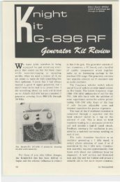
~--t:;~hri E--o--o--<br />
PI-NO<br />
BO~~O<br />
1I • ..<br />
6 14 6 Cl5 SWI<br />
"<br />
.. AO()(O COMPONENTS<br />
TO LI I<br />
a problem, but with careful applicati<strong>on</strong> of<br />
dexterity, the trusty hack saw will solve the<br />
problem. A panel 6~" wide by ~" high is<br />
cut from the right side of the top cover. Replace<br />
the top cover and establish the proper<br />
positi<strong>on</strong> of the newly cut panel. Mark this<br />
positi<strong>on</strong>ing so it may be relocated after the<br />
top is removed. Ilemove top and relocate panel<br />
with flange resting <strong>on</strong> chassis. Mark two or<br />
three places <strong>on</strong> the flan ge for drilling holes<br />
for the bolts that will hold the panel. After<br />
this is d<strong>on</strong>e replace panel and mark the holes<br />
for the chassis. Drill same. Placement of the<br />
comp<strong>on</strong>ents <strong>on</strong> the panel will depend <strong>on</strong> the<br />
parts you usc. In my case the switch is <strong>on</strong> the<br />
left of the panel, the plate tuning capacitor<br />
in the middle, the antenna loading capacitor<br />
<strong>on</strong> the right, and the 80-239 bottom right.<br />
<str<strong>on</strong>g>The</str<strong>on</strong>g> parts may be juggled around so that<br />
everything clears.<br />
<str<strong>on</strong>g>The</str<strong>on</strong>g> <strong>on</strong>ly change in the original circuitry<br />
suggested is to remove L 17, the parasitic<br />
suppressor, and replace with a 47 ohm 2<br />
watt resistor. over which, wind a two tum<br />
coil of number 18 tinned wire.<br />
Coil Ll must be readjusted to produce<br />
about 3.5 rna drive with the bandswitch in<br />
the ten meter positi<strong>on</strong>. This will he the normal<br />
positi<strong>on</strong> of the bandswitch while operating<br />
six meters. (Some loss of drive may occur<br />
while <strong>on</strong> ten meters, in that case LI may<br />
need to be reset while <strong>on</strong> ten). Use an 8 me<br />
crystal in this adjustment.<br />
Tunc up follows the same procedure as the<br />
other bands except that the bund switch must<br />
be <strong>on</strong> ten as menti<strong>on</strong>ed and switch 51 in the<br />
six meter positi<strong>on</strong>. C<strong>on</strong>nect a good antenna<br />
with a low S\VR and you're in business.<br />
This modificati<strong>on</strong> has been in use for over<br />
a year with very good results. All in all it's a<br />
very inexpensive c<strong>on</strong>versi<strong>on</strong>.<br />
P art. List<br />
CI-50 mmfd variable-Bud 1853<br />
C2-250 mmCd ,"ariable-Lafayette MS·2U<br />
Ll--4 !1z turns number 18 J4 in. dia., (res<strong>on</strong>ate with CI at<br />
60 me by sp r ead ing or compressing turns)<br />
J l - SO-239 coaxial c<strong>on</strong>nector<br />
8 WI-One pole. two positi<strong>on</strong>, ceramic switch-<strong>Central</strong>ab<br />
172C<br />
RI-4.7 ohm 2 watt resistor with two turns number 18<br />
wound <strong>on</strong> it.<br />
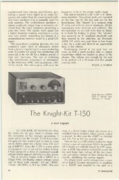
If I owned a Poln-Comm would<br />
I have to buy a VFO?<br />
NO! It's built.in<br />
A microph<strong>on</strong>e?<br />
NO! It's furnished<br />
A mounting bracket?<br />
NO! It's furnished<br />
A n A CIDC power supply?<br />
NO! It's built-in<br />
POLY-COMM@<br />
for a<br />
ora<br />
Wh at's the inside story?<br />
Maximum Performance!<br />
FEATURING • Dual NuVlstor PrE<br />
amp/RF for .1 P.v for 6 db. S + N/N • Notse<br />
figure better than 4 db • Mini·load VFO<br />
for uttn<br />
sr.ble tranemtt end recelve • NOON lfmlting that<br />
wm amaze you • RF output at least lOW <strong>on</strong> 6.<br />
6W <strong>on</strong> 2 • Illuminated "S" meter that doubles f or<br />
tune-up • Heavy gauge perforated steel case •<br />
Handcrafted t efl<strong>on</strong> wiring throughout.<br />
What's the cost?<br />
POLY·COMM "2" $339.50 comple te<br />
POLY·COMM " 6" $319.50 complete<br />
and there's NO EXTRA CHARGE fOR CD UN ITS!<br />
Sounds like a good value, tell me more!<br />
Gladly, just send in th ecoup<strong>on</strong>.<br />
Please se nd complete data <strong>on</strong>:<br />
o PolJ-comm " 6" 0 Poly-comm " 2"<br />
NAM'<br />
ADDRESS<br />
CITY STATE: _<br />
Intend ed use<br />
POLYTRONICS LAB<br />
388 G.tt, Am",<br />
. inc. CLIFTON , NEW JERSEY<br />
_<br />
_<br />
_<br />
JULY 1962<br />
19