PROFI FTN Easytronic Install & Operations Manual 1108.pdf
PROFI FTN Easytronic Install & Operations Manual 1108.pdf
PROFI FTN Easytronic Install & Operations Manual 1108.pdf

Create successful ePaper yourself
Turn your PDF publications into a flip-book with our unique Google optimized e-Paper software.
Warewashers<strong>FTN</strong> Series(<strong>Easytronic</strong>)<strong>Install</strong>ation andoperation InstructionsStarting from Serial No.:8655 0000REV. 11.11.2008
DEGBFNLImportant NotesUse in Accordance with RegulationsHOBART conveyor dishwasher model <strong>FTN</strong> is only intended for cleaning dishes, plates, cups, glasses,cutlery, trays and baking sheets etc.Do not use for electrically heated cooking and heat conservation appliances.SafetyIf a starch attack system is built in, the detergent company has to take care of all relevant safety rulesand regulations. Please avoid any contact with the concentrated detergent.Ensure that the operator wears tight-fitting clothing to prevent trapping hazard by the conveyor.Never hose down the outside of the machine.The "Attention" symbol is shown beside instructions that are essential for thesafe operation of the machine.Please read these passages thoroughly.Liability<strong>Install</strong>ations and repairs which are carried out by non authorized technicians or the use of other thanoriginal spare parts, and any technical alterations to the machine, may affect the warranty setout in the standard conditions of sale.ImportantThis Instruction manual is written for machines with an operating direction from left to right.For machines with an operating direction from right to left, the same information applies but withopposite handling directions.Machine noise level:The machine noise level is 73 dB (A).1458-C-11-08
ContentPage1 aSSEmbly ................................................................................... 41.1 Transport to installation location ..................................................... 41. Remove packing ........................................................................... 41.3 Locating ....................................................................................... 41.4 Adjusting machine height ............................................................... 41.5 Assembly of modules .................................................................... 41.6 Electrical cables ............................................................................ 51.7 Mounting the conveyor .................................................................. 62 connections ............................................................................. 72.1 Electrical connection ..................................................................... 72. Water connection .......................................................................... 82.3 Steam or high pressure hot water connection .................................. 92.4 Exhaust connection ..................................................................... 102.5 Dispensers ................................................................................. 113 First run ................................................................................. 123.1 Preparation ................................................................................. 123. Fill rinse booster heater and tank(s) .............................................. 123.3 Fresh water quantity .................................................................... 123.4 Check ........................................................................................ 133.5 Temperature adjustment .............................................................. 133.6 Adjustment of detergent and rinse aid ........................................... 133.7 Adjustment of timer "fill" ............................................................... 133.8 Auto timer (option) ..................................................................... 133.9 Adjustment of Conveyor speed ..................................................... 133.10 Adjustment of exhaust system ...................................................... 134 controls ................................................................................. 144.1 Temperature display .................................................................... 155 Faults ....................................................................................... 166 pREparation ............................................................................ 177 operation ................................................................................ 188 cleaning .................................................................................. 199 position of curtains .............................................................. 2210 Frost prevention ................................................................... 2311 Troubleshooting ................................................................... 2412 maintenance ........................................................................... 2512.1 Dishwashers with heat pump ........................................................ 25DEGBFNL21458-C-11-08 3
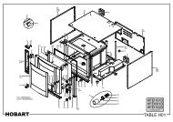
DEGBFNL1 Assembly Should be carried out by HOBART technicians.1.1 Transport to installation location–––––If possible in its packing and on skid.Push on rollers.Avoid damage to floor, doors and to the machine.Remove front covers.If a fork lift is used, put a wooden frame under the machine.1.2 Remove packing––––Cut steel bands.Remove carton.Remove wooden skid.Remove inside packing material and accessories.1.3 Locating–––According to the installation plan.Consider wall clearance according to the installation plan.Consider length of tabling, conveyors, etc.1.4 Adjusting machine height–––To loading platform height of 920 mm above floor or according toinstallation plan by turning the feet.Level floor uneveness.Distribute machine weight equally onto all feet.201.5 Assembly of modules–If the machine is delivered in separate modules, put largest module inplace and level.1.5.1 Sealing Tape––No 168 834Must be stuck on one of the connecting surfaces.The sealing tape must overlap at the corners.AB4 1458-C-11-08
AssemblyBAce d1.5.2 Add next module– Level height (see also 1.4).– Connect by using screws M6 x 12 hex. head, washers, lockwashersand nuts (supplied).– Cut protruding sealing tape with knife.– Connect drain pipes.1.5.3 Tank connectionsConnect all washtanks with the overflow pipes.– Set gasket (A) on the overflow pipe (B).– Put the overflow (B) from the inside of the tank through the prepunchedhole and tighten it with the nut (C).– Move coupling (E) over the pipe (D). Attach the pipe to the overflow (B).Connect coupling (E) with the overflow pipe of the next wash tank.DEGBFNL1.5.4 Transport feet (if exist)Must be removed and returned to HOBART.1.6 Electrical cablesMust be unrolled and drawn through the cable channel.––Connect wires to the terminals of the electrical components.Follow the wiring diagram and the labels on wires and terminals.21458-C-11-08 5
DEGBFNLAssembly1.7 Mounting the conveyor– Remove the chain between conveyor shaft and transport motorof the machine).(end–Put rolled conveyor on exit end of the machine and draw it through themachine.direction of work–Connect both conveyor ends by the conveyor rod.Connect rollers at both ends and lock on with circlips.––Tension the conveyor at the loading section equally on both sides andlock the tension screws (A) with nuts (B).Replace chain between conveyor shaft and transport motor.BA6 1458-C-11-08
2 Connections2.1 Electrical connectionMust be carried out by an authorized technician accordingto the national and local codes.DEGBFNL2.1.1 Check––––Open the control box and take out wiring diagram from the inside ofthe door.The electrical supply shall comply with the name-plate data and thewiring diagram.Line fuses and cable cross section shall comply with the requirements.Supply disconnecting device (main switch with emergency stop function)adjacent to the machine (if not built in).2.1.2 Connection––––Draw cable (H07-RN-F) through cable gland at the bottom of the controlbox rear panel.Connect wires to main terminals or to main switch (if built in).Tighten all terminal screws in the control box (may be loosened duringtransport).Tighten all cable glands.According to EN 60 335 the appliance must be connected to anequipotential conductor.The connecting screw ( ) is located at the rear of control boxbeside the cable inlet.21458-C-11-08 7
DEGBFNLConnections2.2 Water connectionMust be carried out by an authorized technicianaccording to the national and local codes.The machine must be operated with potable water.For water with an extremely high mineral content an externaldemineralisation is strongly recommended.2.2.1 General––Connect water supply and drain pipes according to installation plan.Line strainer and class A air gap are fitted to the machine as standard.2.2.2 Freshwater supply for rinse DN 20 (3/4")––––Should be soft (up to 4° Clark, resp. 0.5 mmol/l).Must be cold if condenser is fitted.Line flow pressure 1.5 - 6 bar at ~ 500 l/hr.Provide shut-off valve.2.2.3 Freshwater supply for fill DN 20 (3/4")–––Should be soft (up to 4° Clark, resp. 0.5 mmol/l) and warm (50 - 60°C).Line flow pressure 1.5 - 6 bar.Provide shut-off valve.2.2.4 Drain connection––To be connected to site drain:Common drain DN 50 (R 2").Provide a siphon.For U.K.:Use straight sleeve type TERRINE 213-15, 1 1 /2" BSPT male.8 1458-C-11-08
DEGBFNLConnections2.4 Exhaust connection––Connection must be carried out in conjunction with competentventilation engineer.Please pay attention to notes on the service drawing.CASE 1:With vent hood (available as an option from HOBART)connected to site exhaust channel with a suction of 1200 m 3 /hr(see picture).250250AB200CCASE 2:With vent hood (available as an option from HOBART)connected horizontally to outside (see picture).–––––With built in additional fan (A).Provide a frost guard (B) (if required).Provide a self closing louver (C) at the outlet (if required).The duct work should be made from SST or plastic material to preventcorrosion problems.A voltage free contact is provided in the machine switch box to controlthe additional fan.250EADB200CASE 3:With vent hood (available as an option from HOBART)connected vertically to outside (see picture).––––––With built in additional fan (A).Provide a frost guard (B) (if required).Provide a roof seal (D) at the duct work.Provide a cover (E) at the duct work outlet.The duct work should be made from SST or plastic material to preventcorrosion problems.A voltage free contact is provided in the machine switch box to controlthe additional fan.10 1458-C-11-08
DEGBFNL3 First runMust be carried out by an authorized Service technicianto adjust and check machine functions!See also chapter 4 "Controls".3.1 Preparation––––Switch off main switch.Make sure, that detergent and rinse aid containers are filled.Open water supply.Open control box and switch on all circuit breakers and motorprotection switches.Exception: if electrical rinse booster heater is installed, makesure that its sealed protection switch is switched off (see wiringdiagram).––Close inspection doors.Switch on main switch.3.2 Fill rinse booster heater and tank(s)–––Press the contactor for the pressure pump of fresh water storage tankuntil water sprays out of the rinse jets.Check if all rinse jets sprays correctly.If not: remove rinse arms and clean jets.Switch off main switch.Electrically heated machine:– Remove the red sticker from the protection switch of rinse boosterheater (A) and switch on protection switch (B).Steam- / high pressure hot water heated machine:– Open shut-off valves.–Close control box.–––Switch on main switch and set ON / OFF-switch to "fill" position.After reaching the correct water level, filling switches off automaticallyand the tank heating(s) switch(es) on.When correct temperatures obtained (the green OK pilot lightilluminates), the machine is ready for operation.3.3 Fresh water quantityThe fresh water quantity is adjusted at the factory and may not bechanged.If a new adjustment is needed, please call the after-sales service.12 1458-C-11-08
First run3.4 Check–Direction of rotation of motors (see direction sign):- Pumps- Conveyor motor- Exhaust fan- Dryer fan (if dryer is fitted).If motor runs against the indicated direction, interchange 2 of 3 phasesat the terminal.DEGBFNL–Check and eliminate potential leakages.3.5 Temperature adjustmentTemperatures are pre-adjusted at the factory.If a new adjustment is needed, please call the after-sales service.3.6 Adjustment of detergent and rinse aidShould be done by the detergent and rinse aid supplier.3.7 Adjustment of timer "fill"The timer is pre-adjusted at the factory.If a new adjustment is needed, please call the after-sales service.3.8 Auto timer (option)The timer is pre-adjusted at the factory.Wash, rinse and dryer (if fitted) operate only if washware is passingthrough the machine.These functions switch off automatically if no further washware follows.The delay times can be adjusted by authorized Service technicians.3.9 Adjustment of Conveyor speedBy using the selection switch ➃.If changement is needed, please call the after-sales service.3.10 Adjustment of exhaust systemShould be adjusted by a qualified Service technician.(Required exhaust volume at site is 1200 m 3 /h.)If a new adjustment is needed, please call the after-sales service.21458-C-11-08 13
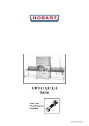
DEGBFNL4 Controls5 6 7 9ON - OFF1311101 3 2 4 14 8121 ON / OFF switch(illuminates during drain cycle)Switches the machine on or off.Starts the fill cycle (exhaust and heating will startautomatically) or drain the tanks.2 Conveyor ON buttonSwitches the conveyor of the machine on.The wash cycle will start automatically.3 Conveyor OFF buttonSwitches the conveyor and wash off.4 Conveyor speed selection switchI = slow (e.g. for containers)II = middle (according DIN 10 510)III = fast (nominal speed)5 OK pilot light (green)Indicates, that the machine is ready for use.6 Temperature display – washIndicates the current temperature of the last washtank.7 Temperature display – rinseIndicates the current temperature of the final rinsewater.8 Temperature display buttonBy pushing this button the display indicatesindividual tank temperatures or dryer temperature(see chapter 4.1).9 Warning light (red)Indicates that a motor protection switch has cut outor one of the temperature probes is defective.The wash temperature display ➅ indicates the No.of the defect probe, the rinse temperature display ➆indicates the failure.(e.g.: S = short circuit, L = open circuit)10 Conveyor ON button at the loading section (option)Switches the conveyor of the machine on.The wash cycle will start automatically.11 Conveyor OFF button at the loading section(option)Switches the conveyor and wash off.12 Main switchMust be on position I during operation and onposition 0 during repair and maintenance.13 Emergency Stop button (option)Switches the machine off.Must be unlocked for operation.14 High pressure button (option)(illuminates during high pressure mode)Switches on the high pressure pump.To switch the high pressure off, press the buttonagain.14 1458-C-11-08
Controls4.1 Temperature displayBy pushing this button ➇, individual temperatures (such as pre-wash,wash, rinse or dryer) can be displayed.Press the temperature display button.Wash- ➅ and rinse ➆ temperature display changes into the displaymode. The wash temperature display ➅ indicates the selectedmeasuring point, the rinse temperature display ➆ indicates the currenttemperature.DEGBFNLMeasuring point 1Indicates the current prewash temperature (L or S-tank).(E-prewash will not be indicated.)Measuring point 2Indicates the current temperature at wash tank 1.(Valid only for machines with more than one main wash tank.)Measuring point 3Indicates the current temperature at wash tank 2.(Valid only for machines with three main wash tanks.)Measuring point 4Indicates the current temperature of the last wash tank prior to therinse.Measuring point 5Indicates the current final rinse temperature.Measuring point 6Indicates the current dryer temperature (if a dryer is fitted).By pushing the temperature display button again, the displaychanges back into the basic mode.(Current wash and rinse temperature display.)21458-C-11-08 15
DEGBFNL5 FaultsIf a failure arises during operation, it will be indicated by the flashing of thered warning light.–The flashing of warning light without other information at the temperaturedisplays (➅ and ➆), indicates a motor fault.–The flashing of warning light and a further indication appears at thetemperature displays, it indicates a temperature probe fault (shortcircuit or open circuit).Example:The warning light flashes and the left temperature display ➅ shows F 1,and the right display ➆ shows an S or L.This means:The temperature probe F 1 failed by a short circuit (S) or an opencircuit (L).16 1458-C-11-08
6 PreparationDEGBFNLPut curtains in place(see page 22).Put the flat strainers in place.Put the strainer baskets in place.Place pump intake strainers inposition at the bottom of wash tank(rinse section).Put the rinse strainer in place.Check if entry section strainer is inposition.Put the dryer deflector pan in place.Set wash arms in place:Upper: set wash arm in side guides,move to end position and drop-inover stop unit.Lower: move wash arm in sideguides to end position and click intoplace.Set rinse arms in place:Upper: set rinse arm in back opening,move from below into guide andclick into place.Lower: move rinse arm in guides toend position and click into place.21458-C-11-08 17
DEGBFNL7 Operation (Remove coarse food soil before washing.)Close inspection doors.Open shut-off valve at site.Switch on main switch and set theON / OFF-switch to "fill" position.Fill, exhaust and heating elementsstart automatically.Wait until the green OK lightilluminates.Push the conveyor ON button.The conveyor will start.Put the washware on conveyor.Use loading platform to stack plates.Load plates on conveyorLoad trays onto conveyor crosswise.Do not mix trays and plates(shadow zones).Put soup cups with inclination to themachine on 2 pegs of conveyor.Do not place soup cups vertically onconveyor.Put glasses and cups with the openingdownward into the rack.Glasses should not touch each other(glass fracture).Use the suitable rack.18 1458-C-11-08
OperationDEGBFNLPut cutlery vertically and unsortedwith handle downwards into cutleryracks.Set the cutlery rack on a utensil rackand place onto conveyor.Wash utensils in utensil rack. Putthe rack on conveyor. Check that nogrips or handles protrude throughthe rack or conveyor.Put gastronorm pan and other bowlswith openings downward on conveyorwith inclination to side.Washware may not exceedmaximum loading heightand width.Pass through insulated trays with theopenings downward and crosswise.Do not set the insulated trays withopenings upward on conveyor.Water would stay in the recesses.Let the washware be transportedclose to the end of the conveyor togive enough time to dry.8 Cleaning (Consider your local hygiene rules.)Push the conveyor OFF button.Conveyor and wash stop.Then set the ON / OFF switch to"drain" position. The machine will beemptied.Exhaust and heating will stop automatically.Open inspection doors. Take out curtains (see page 22).21458-C-11-08 19
DEGBFNLCleaningRemove strainer baskets. Remove flat strainers. Remove the rinse strainer.Wait until the tanks are completely emptied.Set the ON / OFF switch to "0" position.Switch off main switch!Remove pump intake strainers (rinsesection).Remove strainer from the entrysection.Remove dryer deflector pan.Do not knock strainersto remove food soil !They could be damaged.Hose down and brush the strainers.Remove wash arms:Upper: lift wash arm over stop unitand pull out.Lower: lift wash arm to pull out.Remove end caps and clean washarms accurately.Remove rinse arms:Upper: pull spring towards front andremove rinse arm.Lower: lift rinse arm and pull out.Control nozzle openings and clean ifnecessary.20 1458-C-11-08
CleaningDEGBFNLOpen the cover and hose down theinterior of the entry section.Remove the side panels of the exitand clean it.Hose down and clean the interior ofthe machine.To clean the machine do not use any chloric, acidic or abrasive productsand no metallic brushs.Never hose down the exterior of the machine.Clean (once a month)Remove front panel of thecondensers.Hose down condensers.To drain the tanks switch on mainswitch, set the ON / OFF switch tothe "drain" position.The drain valves will be openedagain.When the tanks are completelyempty, set the ON / OFF switch tothe "0" position.Switch off the main switch andclose shut-off valves at site.Leave the inspection doors open forventilation.21458-C-11-081
DEGBFNL9 Position of curtainsL-AThe working direction asshown is left/right.On working directionright/left the positionof curtains is reversed.S-AE-S-AS-DAL AN-RS AN-R➁ *Curtain at split point notapplicable for <strong>FTN</strong> ProfiRev. 7 - 10.10.2007When necessary:Spread out the curtains and put them lengthwiseon the conveyor belt to clean.22 1458-C-11-08
10 Frost prevention (where required)Must be carried out by an authorizedService technician!Drain machine (start drain cycle).Set main switch to "0".Switch off the protection switch of the electrical rinse boosterheater!DEGBFNLAll tanks, water pipework and armatures must be totally drained.– Close shut-off valves at site.– Remove plug at the bottom of the break tank.– Remove plug at the bottom of the rinse booster heater.– Disconnect pipe after the non-return valve and let it drain.– Drain site water pipework.– Drain traps of drain system.– Steam or hot water heated machines:drain all heating coils and pipes.– The condenser if fitted, must be blown out with compressed air.–Reset for operation according to chapter 3.21458-C-11-083
DEGBFNL11 TroubleshootingFAULT CAUSE REMEDYTank fill too slow. Line strainer of fill clogged. Clean line strainer.Solenoid valve defective.Shut off valve at site is not correct open.Call the after sales service.Open the shut off valve at site.Tank not filled to correct level. Fill cycle too short. Call the after sales service.Steam escapes from loadingor exit section.Shut off valve at site is not correct open.Exhaust extraction too low.Open the shut off valve at site.Call the after sales service.Wrong position of curtains. Check curtains (see chapter 9).Temperatures too low. Too much exhaust extraction. Call the after sales service.Washware soiled afterdishwashing.Streaks and spots onwashware.Washware do not dry.Heaters defective.Strainers wrongly positioned.Check heaters.Call the after sales service.Check strainers.Curtains not fitted or wrongly placed. Check curtains (see chapter 9).Wash jets clogged.Too low detergent concentration.Too much foam.Excessive food debris entering machine.Temperatures too low.Conveyor speed too high.Strainers wrongly positioned.Clean the wash arms.Increase detergent dispensing.Use non-foaming detergent only.Check pre-scrapping procedure.Check heating system.Select lower speed.Check strainers.Wash water splashes into rinse section. Check curtains (see chapter 9).Rinse jets clogged.Inadequate rinse aid dispensing.Too high mineral content of rinse water.Incorrect temperature or humidity ofdrying air.Conveyor speed too high.Clean rinse jets.Get the dispenser adjusted.Use of demineralized water recommended.Check heater and blower of drying unit.Select lower speed.Drops on washware. Inadequate rinse aid concentration. Get concentration increased.Dishes tilt over. Water pressure from below too high. Replace reducer between lower wash arm and washpipe.Machine out of order, displayswitched off.Upper wash arms clogged.Items too light.Main switch switched off, power supplycompletely cut-off.Emergency switch cut-off, power supplycompletely cut-off.Remove wash arms and clean.Use cover on racks.Switch on main switch, re-start machine.Switch on emergency switch, re-start machine.24 1458-C-11-08
12 MaintenanceFor trouble free operation we recommend an inspection or maintenancecontract by qualified Service technicians.DEGBFNL12.1 Dishwashers with heat pumpThe heat pump built-in in your dishwasher contains fluorinatedgreenhouse gases covered by the Kyoto Protocol and thereforeit falls within the scope of the EC Regulation 842/2006.As this is not a hermetically sealed system and the refrigerant chargeis more than 3kg, you are obligated as operator of the refrigerationequipment to carry out following measures:––––––At suspicion of refrigerant charge loss a leakage check bycertified personnel has to be arranged as soon as possible and ifnecessary the repair.Equipments containing the refrigerant has to be checked for leakageby certified personnel at least once every 12 months.Any detected leakage must be repaired immediately by certifiedpersonnel.After a leak has been repaired, the equipment has to be checked againfor leakage within one month.When putting the equipment out of operation, you are responsible thatthe refrigerant contained in the equipment is proper disposed of bycertified personnel.The above mentioned determinations and/or measures must berecorded.These records have to be kept at least 5 years and submitted to thecompetent authority on request.For the recording of checking, determinations and measures werecommend to use the following forms.21458-C-11-085
Records about the results of the leakage checksManufacturer’s data:HOBART GmbH, Robert-Bosch-Straße 17, 77656 Offenburg, GermanyHeat pump Manufacturer, Type: HOBART HP- / FHP-Year of manufacture:Serial-No:Refrigerant:R134aRefrigerant charge heating circuit tank:kgRefrigerant charge heating circuit final rinse water:kgLeakage check done at manufacturer: Date: Inspector:Operators data:Name:Postal address:<strong>Install</strong>ation location:Telephone:Leakage checks and results of all regular routine tests, if necessary longer downtimes, final decommissioning /scrapping:InspectiondateDetected defectcheckedCompany Name SignatureNextinspectionATTention: These records have to be kept at least 5 years after the last entry and be submitted to thecompetent authority on request.26
Noticed defects and their repairingInspectiondateDetected defectRepair – If necessary modification /replacement of components* Refrigerant R134a refilled,recovered, discharged (kg)* If necessary detailed information about refilled refrigerant: Kind of the refrigerant (new / reused / recyceltes).If necessary analysis of the reused refrigerant; if necessary origin of the reused refrigerant.ATTention: These records have to be kept at least 5 years after the last entry and be submitted to thecompetent authority on request.27
As continued product improvement is a policy of HOBART, specifications are subject to change without notice.Printed in GermanyaG-21458-C-11-08-PC