LCC Series - Pulsotronic GmbH & Co. KG
LCC Series - Pulsotronic GmbH & Co. KG
LCC Series - Pulsotronic GmbH & Co. KG

Create successful ePaper yourself
Turn your PDF publications into a flip-book with our unique Google optimized e-Paper software.
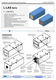
<strong>LCC</strong> <strong>Series</strong> • Laser <strong>Co</strong>py <strong>Co</strong>unters<br />
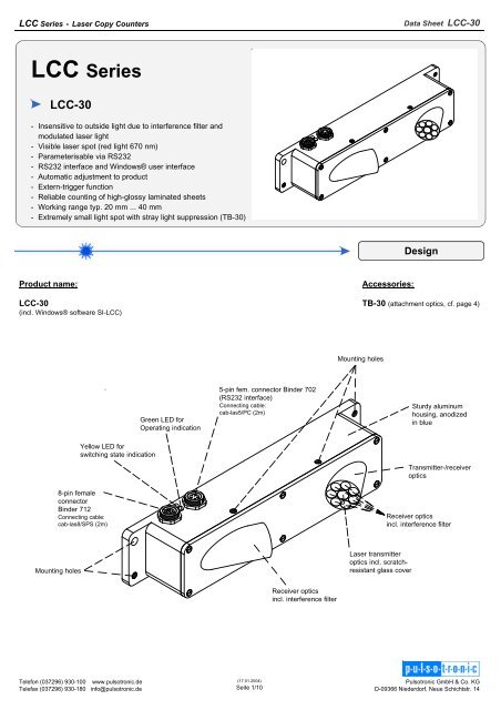
<strong>LCC</strong> <strong>Series</strong><br />
<strong>LCC</strong>-30<br />
- Insensitive to outside light due to interference filter and<br />
modulated laser light<br />
- Visible laser spot (red light 670 nm)<br />
- Parameterisable via RS232<br />
- RS232 interface and Windows® user interface<br />
- Automatic adjustment to product<br />
- Extern-trigger function<br />
- Reliable counting of high-glossy laminated sheets<br />
- Working range typ. 20 mm ... 40 mm<br />
- Extremely small light spot with stray light suppression (TB-30)<br />
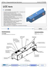
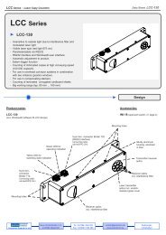
Product name:<br />
<strong>LCC</strong>-30<br />
(incl. Windows® software SI-<strong>LCC</strong>)<br />
Mounting holes<br />
Yellow LED for<br />
switching state indication<br />
8-pin female<br />
connector<br />
Binder 712<br />
<strong>Co</strong>nnecting cable:<br />
cab-las8/SPS (2m)<br />
Telefon (037296) 930-100 www.pulsotronic.de<br />
Telefax (037296) 930-180 info@pulsotronic.de<br />
Green LED for<br />
Operating indication<br />
5-pin fem. connector Binder 702<br />
(RS232 interface)<br />
<strong>Co</strong>nnecting cable:<br />
cab-las5/PC (2m)<br />
(17.01.2004)<br />
Seite 1/10<br />
Receiver optics<br />
incl. interference filter<br />
Mounting holes<br />
Accessories:<br />
Laser transmitter<br />
optics incl. scratchresistant<br />
glass cover<br />
Data Sheet <strong>LCC</strong>-30<br />
Design<br />
TB-30 (attachment optics, cf. page 4)<br />
Sturdy aluminum<br />
housing, anodized<br />
in blue<br />
Transmitter-/receiver<br />
optics<br />
Receiver optics<br />
incl. interference filter<br />
<strong>Pulsotronic</strong> <strong>GmbH</strong> & <strong>Co</strong>. <strong>KG</strong><br />
D-09366 Niederdorf, Neue Schichtstr. 14
<strong>LCC</strong> <strong>Series</strong> • Laser <strong>Co</strong>py <strong>Co</strong>unters<br />
Model <strong>LCC</strong>-30<br />
Laser<br />
Telefon (037296) 930-100 www.pulsotronic.de<br />
Telefax (037296) 930-180 info@pulsotronic.de<br />
(17.01.2004)<br />
Seite 2/10<br />
Data Sheet <strong>LCC</strong>-30<br />
Semi-conductor laser, 670 nm, AC operation, 1 mW max. opt. power, laser class 2 acc. to DIN EN 60825.<br />
The use of this laser sensor therefore requires no additional protective measures.<br />
Optical filter Red light filter RG630 and interference filter<br />
Digital output<br />
pnp bright-switching/npn dark-switching or pnp dark-switching/npn bright-switching (OUT0 and OUT1),<br />
adjustable under Windows® on PC<br />
Voltage supply +12 VDC ... +30 VDC<br />
Sensitivity setting adjustable under Windows® on PC<br />
Laser power correction adjustable under Windows® on PC<br />
Current consumption typ. 150 mA<br />
Dead time adjustable under Windows® on PC<br />
Dead time mode static or dynamic, adjustable under Windows® on PC<br />
Enclosure rating IP54<br />
Operating temperature range -20°C ... +50°C<br />
Storage temperature range -20°C ... +85°C<br />
Housing material Aluminum, anodized in blue<br />
Housing dimensions approx. 205 mm x 40 mm x 40 mm<br />
Type of connector<br />
8-pin female connector type Binder <strong>Series</strong> 712<br />
5-pin female connector type Binder <strong>Series</strong> 702<br />
EMC test acc. to IEC - 801 ...<br />
Scan frequency typ. 15 kHz (without averaging)<br />
Switching state indication Visualization by means of a yellow LED<br />
Dynamic output<br />
(pulse lengthening)<br />
adjustable under Windows® on PC<br />
Max. switching current 100 mA, short-circuit protected<br />
Interface RS232, parameterizable under Windows®<br />
<strong>Co</strong>nnecting cables<br />
<strong>Co</strong>nnection to PC: cab-las5/PC (2m)<br />
<strong>Co</strong>nnection to PLC: cab-las8/SPS (2m)<br />
Modulation frequency typ. 100 kHz<br />
Max. product stream typ. 500 000 copies/h<br />
Min. height of object typ. 0.1 mm<br />
Output polarity Bright-/dark-switching, can be adjusted under Windows® on PC<br />
Working range typ. 20 mm ... 40 mm (with tube TB-30: typ. 27 mm ... 33 mm)<br />
Technical Data<br />
<strong>Pulsotronic</strong> <strong>GmbH</strong> & <strong>Co</strong>. <strong>KG</strong><br />
D-09366 Niederdorf, Neue Schichtstr. 14
<strong>LCC</strong> <strong>Series</strong> • Laser <strong>Co</strong>py <strong>Co</strong>unters<br />
Telefon (037296) 930-100 www.pulsotronic.de<br />
Telefax (037296) 930-180 info@pulsotronic.de<br />
optische Achse<br />
(17.01.2004)<br />
Seite 3/10<br />
Data Sheet <strong>LCC</strong>-30<br />
Dimensions<br />
All dimensionsin mm<br />
Working Distance<br />
All dimensionsin mm<br />
<strong>Pulsotronic</strong> <strong>GmbH</strong> & <strong>Co</strong>. <strong>KG</strong><br />
D-09366 Niederdorf, Neue Schichtstr. 14
<strong>LCC</strong> <strong>Series</strong> • Laser <strong>Co</strong>py <strong>Co</strong>unters<br />
Tube TB-30<br />
(for transmitter-/receiver optics)<br />
Telefon (037296) 930-100 www.pulsotronic.de<br />
Telefax (037296) 930-180 info@pulsotronic.de<br />
(17.01.2004)<br />
Seite 4/10<br />
Data Sheet <strong>LCC</strong>-30<br />
Accessories<br />
All dimensions in mm<br />
<strong>Pulsotronic</strong> <strong>GmbH</strong> & <strong>Co</strong>. <strong>KG</strong><br />
D-09366 Niederdorf, Neue Schichtstr. 14
<strong>LCC</strong> <strong>Series</strong> • Laser <strong>Co</strong>py <strong>Co</strong>unters<br />
<strong>Co</strong>nnection to PLC:<br />
8-pin female connector Binder <strong>Series</strong> 712<br />
Pin No. <strong>Co</strong>lor Assignment<br />
1 wht GND (0V)<br />
2 brn +24VDC<br />
3 grn IN0<br />
4 yel IN1<br />
5 gry OUT0<br />
6 pnk OUT1<br />
7 blu n.c.<br />
8 red n.c.<br />
<strong>Co</strong>nnecting cables:<br />
cab-las8/SPS Length: 2 m Outer jacket: PUR<br />
cab-las5/PC Length: 2 m Outer jacket: PUR<br />
Telefon (037296) 930-100 www.pulsotronic.de<br />
Telefax (037296) 930-180 info@pulsotronic.de<br />
cab-las8/SPS cab-las5/PC<br />
The laser copy counters of <strong>LCC</strong> <strong>Series</strong> comply with laser class 2<br />
according to EN 60825. The use of these laser transmitters<br />
therefore requires no additional protective measures.<br />
The laser copy counters of <strong>LCC</strong> <strong>Series</strong> are supplied with a<br />
laser warning label.<br />
<strong>Co</strong>nnection to PC:<br />
5-pin female connector Binder <strong>Series</strong> 702<br />
Pin No. Assignment<br />
1 GND (0V)<br />
2 TX0<br />
3 RX0<br />
4 n.c.<br />
5 n.c.<br />
(17.01.2004)<br />
Seite 5/10<br />
Data Sheet <strong>LCC</strong>-30<br />
<strong>Co</strong>nnector Assignment<br />
<strong>Co</strong>nnecting Cables<br />
Laser Warning<br />
LASER RADIATION<br />
DO NOT STARE INTO THE BEAM<br />
CLASS II LASER PRODUCT<br />
<strong>Pulsotronic</strong> <strong>GmbH</strong> & <strong>Co</strong>. <strong>KG</strong><br />
D-09366 Niederdorf, Neue Schichtstr. 14
<strong>LCC</strong> <strong>Series</strong> • Laser <strong>Co</strong>py <strong>Co</strong>unters<br />
Windows® software SI-<strong>LCC</strong> V1.0:<br />
The <strong>LCC</strong>-30 laser copy counter can be easily parameterised with the Windows® user interface.<br />
For this purpose the <strong>LCC</strong>-30 system is connected to the PC with the serial interface cable cab-las5/PC.<br />
When parameterisation is finished, the PC can be disconnected again.<br />
Windows® user interface:<br />
Telefon (037296) 930-100 www.pulsotronic.de<br />
Telefax (037296) 930-180 info@pulsotronic.de<br />
(17.01.2004)<br />
Seite 6/10<br />
Data Sheet <strong>LCC</strong>-30<br />
Parameterization<br />
PMOD:<br />
In this function field the operating mode of automatic power correction at the transmitter unit (laser) can be set.<br />
FIX: The POWER slide is enabled for setting purposes. The laser transmission power is kept constant at the<br />
value set with the POWER slide.<br />
DYN: The LED transmission power is automatically and dynamically controlled in accordance with the amount of<br />
radiation that is diffusely reflected from the object. By using the intensities measured at the receiver,<br />
the automatic control circuit attempts to adjust the transmission power in such a way that the dynamic range<br />
is not exceeded.<br />
POWER[%]:<br />
In this function field the intensity of the laser diode can be set by using the slide or by entering a value in the edit box.<br />
HOLD:<br />
In this function field the pulse lengthening time [ms] (after detecting an edge) for OUT0 can be set.<br />
ADD PARA:<br />
This changeover switch determines<br />
whether the parameters BACKLIM,<br />
REGCNT, AVERAGE, DEAD TIME<br />
MODE, and DEAD TIME are displayed<br />
or hidden.<br />
OFF = Hide parameters<br />
<strong>Pulsotronic</strong> <strong>GmbH</strong> & <strong>Co</strong>. <strong>KG</strong><br />
D-09366 Niederdorf, Neue Schichtstr. 14
<strong>LCC</strong> <strong>Series</strong> • Laser <strong>Co</strong>py <strong>Co</strong>unters<br />
HYSTERESIS<br />
THRESHOLD<br />
OUT0 with<br />
OUTMODE = direct<br />
OUT0 with<br />
OUTMODE = inverse<br />
NORM<br />
MIN<br />
Telefon (037296) 930-100 www.pulsotronic.de<br />
Telefax (037296) 930-180 info@pulsotronic.de<br />
HOLD<br />
HOLD<br />
(17.01.2004)<br />
Seite 7/10<br />
Data Sheet <strong>LCC</strong>-30<br />
Parameterization<br />
ADD PARA:<br />
This changeover switch determines<br />
whether the parameters BACKLIM,<br />
REGCNT, AVERAGE, DEAD TIME<br />
MODE, and DEAD TIME are displayed<br />
or hidden.<br />
ON = Display parameters<br />
THRESHOLD:<br />
Input field for the lower threshold. The sensor sensitivity increases with a higher THRESHOLD value.<br />
HYSTERESIS:<br />
Input field for the desired hysteresis. For detecting an edge, the NORM VALUE of the two RAW<br />
SIGNALS must drop below a certain THRESHOLD during measurement to initiate a counting event.<br />
When the sensor detects an edge (NORM<br />
VALUE drops below THRESHOLD), a<br />
search for the minimum NORM VALUE is<br />
performed until the end of the DEAD<br />
TIME (TRIGGER=CONT) or the ACTIVE<br />
TIME (TRIGGER=EXT) and during<br />
HOLD. This minimum value is stored in a<br />
16-value JUMP-BUFFER that can be read<br />
out with the GETBUFF software button.<br />
After the value has dropped below a<br />
THRESHOLD, the NORM VALUE must<br />
again lie above the value set under<br />
HYSTERESIS, to allow renewed edge<br />
detection. This is an additional safety<br />
feature to suppress multiple counting<br />
around the THRESHOLD.<br />
<strong>Pulsotronic</strong> <strong>GmbH</strong> & <strong>Co</strong>. <strong>KG</strong><br />
D-09366 Niederdorf, Neue Schichtstr. 14
<strong>LCC</strong> <strong>Series</strong> • Laser <strong>Co</strong>py <strong>Co</strong>unters<br />
TRIGGER = CONT:<br />
Measurement is performed continuously.<br />
Telefon (037296) 930-100 www.pulsotronic.de<br />
Telefax (037296) 930-180 info@pulsotronic.de<br />
(17.01.2004)<br />
Seite 8/10<br />
Data Sheet <strong>LCC</strong>-30<br />
Parameterization<br />
TRIGGER = EXT:<br />
An ACTIVE WINDOW is set for the sensor by the two inputs IN0 and IN1. The window is opened with a positive signal edge at IN0, and is closed<br />
again with a positive signal edge at IN1. The sensor measures during its ACTIVE TIME, and if it detects an edge, an output counting pulse is<br />
provided immediately after the ACTIVE WINDOW is closed.<br />
Only one edge can be detected during the ACTIVE TIME. Output OUT1 serves for monitoring the active time. For renewed edge detection, the two<br />
inputs must detect a negative signal edge.<br />
Application example:<br />
Objects that are transported by means of mechanical or<br />
other kinds of grippers. The trigger signals (+24V) can be<br />
supplied to the sensor by means of inductive sensor or<br />
light barriers, etc. The advantage of this method of<br />
measuring is that the sensor is completely independent<br />
of the speed.<br />
TRIGGER = ADJ EXT:<br />
For future measurements with an active window (TRIGGER =<br />
EXT), this mode makes it easier for the user to adjust the two<br />
initiators for the active window; see picture below.<br />
For operating the sensor with an active window, two initiators<br />
must inform the sensor about the active time. As described<br />
above, the active window is opened with a positive signal<br />
edge at input IN0 and is closed again with a positive signal<br />
edge at input IN1.<br />
The TRIGGER = ADJ EXT mode was introduced to allow<br />
improved sensor adjustment. When this mode is selected, the<br />
sensor records the time from one positive signal edge at IN0<br />
to the next positive signal edge at IN0 and valuates this time<br />
as 100%. This is shown in the graphic display, when the GO<br />
button is pressed and TYPE = EXT is selected. When the GO<br />
button is pressed, the data are automatically updated after<br />
one second. The value of 100 on the x-axis corresponds with<br />
100% (time from IN0 to IN0).<br />
The red graph visualised the length of the active window in<br />
percent of the time between IN0 and IN0.The blue graph<br />
visualises the appearance of an edge in percent of the time<br />
between IN0 and IN0.<br />
It can be seen in the example shown here that the active<br />
window is equal to 61% of the time from IN0 to IN0, i.e. the<br />
sensor detected a positive signal edge at IN1 after 61% of IN0<br />
to IN0, which closed the active window. The edge was<br />
detected at 30% of IN0 to IN0. These two values are also<br />
shown in the EDGE [%] and WIN [%] display fields.<br />
In practice, the active window should be open approx. 60% of<br />
IN0 to IN0. The edge should lie in the middle of the active<br />
window (30%).<br />
IN0<br />
IN1<br />
OUT1<br />
OBJEKT<br />
OUT0<br />
= direct<br />
AKTIV<br />
FENSTER<br />
JA<br />
HOLD<br />
AKTIV<br />
FENSTER<br />
NEIN<br />
<strong>Pulsotronic</strong> <strong>GmbH</strong> & <strong>Co</strong>. <strong>KG</strong><br />
D-09366 Niederdorf, Neue Schichtstr. 14
<strong>LCC</strong> <strong>Series</strong> • Laser <strong>Co</strong>py <strong>Co</strong>unters<br />
Telefon (037296) 930-100 www.pulsotronic.de<br />
Telefax (037296) 930-180 info@pulsotronic.de<br />
(17.01.2004)<br />
Seite 9/10<br />
Data Sheet <strong>LCC</strong>-30<br />
Parameterization<br />
BACKLIM:<br />
In this edit-box an intensity limit can be set. If the intensity that arrives at the receiver unit DAT0<br />
(display window in the user interface) drops below this limit, no evaluation will be performed.<br />
REGCNT:<br />
This edit-box serves for setting after how many loop runs dynamic laser diode correction should be<br />
performed.<br />
Example: SCAN frequency 15 kHz is equal to 66.6 µs<br />
REGCNT = 75<br />
Calculation: 66.6 µs * 75 = 5 ms<br />
Result: Dynamic correction is performed every 5ms<br />
Explanation: Flatly rising magazines are detected, because dynamic correction is not performed<br />
with every loop run, and the jump is automatically compensated, so to speak.<br />
AVERAGE:<br />
Tthis edit-box serves for setting averaging through NORM.<br />
The minimum value for averaging is 1.<br />
The maximum value for averaging is 128.<br />
An average of 1 is sufficient for most applications.<br />
Please note:<br />
If AVERAGE = 1, the internal scan frequency = 15 kHz.<br />
If AVERAGE = 2, the internal scan frequency = 7.5 kHz.<br />
If AVERAGE = 4, the internal scan frequency = 3.75 kHz.<br />
etc.<br />
OUTMODE:<br />
This edit-box determines how the output impulse should be output at OUT0:<br />
Direct:<br />
When a counting event occurs, output OUT0 changes from LOW (0V) to HIGH (+24V),<br />
until HOLD is over.<br />
Inverse:<br />
When a counting event occurs, output OUT0 changes from HIGH (+24V) to LOW (0V),<br />
until HOLD is over.<br />
DEAD TIME MODE:<br />
This function field shows the DEAD TIME MODE that is used.<br />
DEAD TIME MODE = FIX:<br />
A fixed dead time is used. The dead time is set in milliseconds under DEAD TIME [ms].<br />
DEAD TIME MODE = DYN:<br />
A dynamic dead time is used. The dead time is set in percent under DEAD TIME [%].<br />
The time between two edges is valuated as 100%.The dead time is calculated in accordance with<br />
the percent value that is set under DEAD TIME [%]. The dead time can be measured through<br />
monitor output OUT1 (low-active).<br />
If TRIGGER = EXT is selected, the sensor operates with an ACTIVE TIME. In this case the input<br />
fields DEAD TIME MODE and DEAD TIME [...] are disabled. The active time can be measured<br />
through monitor output OUT1 (low-active).<br />
<strong>Pulsotronic</strong> <strong>GmbH</strong> & <strong>Co</strong>. <strong>KG</strong><br />
D-09366 Niederdorf, Neue Schichtstr. 14
<strong>LCC</strong> <strong>Series</strong> • Laser <strong>Co</strong>py <strong>Co</strong>unters<br />
Telefon (037296) 930-100 www.pulsotronic.de<br />
Telefax (037296) 930-180 info@pulsotronic.de<br />
(17.01.2004)<br />
Seite 10/10<br />
Data Sheet <strong>LCC</strong>-30<br />
Parameterization<br />
TYPE:<br />
The data that are to be displayed in the graphic window (RAW, NORM) can be selected in this<br />
function field.<br />
RAW:<br />
The raw data DAT0 and DAT1 are visualised in the graphic window. In addition these values are<br />
displayed in the two numerical value output fields DAT0 and DAT1.<br />
NORM:<br />
The NORM calculated from DAT0 and DAT1 is displayed in the graphic window. In addition this<br />
value is displayed in the numerical value output field NORM.<br />
GETBUFF:<br />
When the GETBUFF button is clicked, the last minimum values of the NORM SIGNAL after edge<br />
detection are displayed.<br />
Upon detection of an edge the sensor starts to search the minimum value of the NORM SIGNAL<br />
during the DEAD TIME and HOLD. This value is then stored in a 16-value ring buffer. Based on<br />
these VALUES, the optimum THRESHOLD for the current product run can then be set.<br />
MEM:<br />
This group of function keys serves for parameter exchange between the PC and the control unit<br />
through the serial RS232 interface.<br />
SEND:<br />
When the SEND button is clicked, all the currently set parameters are transferred between the PC<br />
and the control unit or to an output file. The target of the respective parameter transfer is<br />
determined by the selected button (RAM, EE, or FILE).<br />
GET:<br />
The current setting values can be called up from the control unit by clicking on the GET button. The<br />
source of data exchange is determined by the selected button (RAM, EE, or FILE).<br />
RAM:<br />
The current parameters are written to the RAM memory of the control unit, or they are read from<br />
the RAM, i.e. these parameters are lost again when the voltage is switched off at the control unit.<br />
EE:<br />
The current parameters are written to the non-volatile memory of the EEPROM in the control unit,<br />
or they are read from the EEPROM, i.e. the parameters in the internal EEPROM are stored when<br />
the voltage is switched off.<br />
<strong>Pulsotronic</strong> <strong>GmbH</strong> & <strong>Co</strong>. <strong>KG</strong><br />
D-09366 Niederdorf, Neue Schichtstr. 14