to Download PDF 3.44MB - KLINGER Australia
to Download PDF 3.44MB - KLINGER Australia
to Download PDF 3.44MB - KLINGER Australia

You also want an ePaper? Increase the reach of your titles
YUMPU automatically turns print PDFs into web optimized ePapers that Google loves.
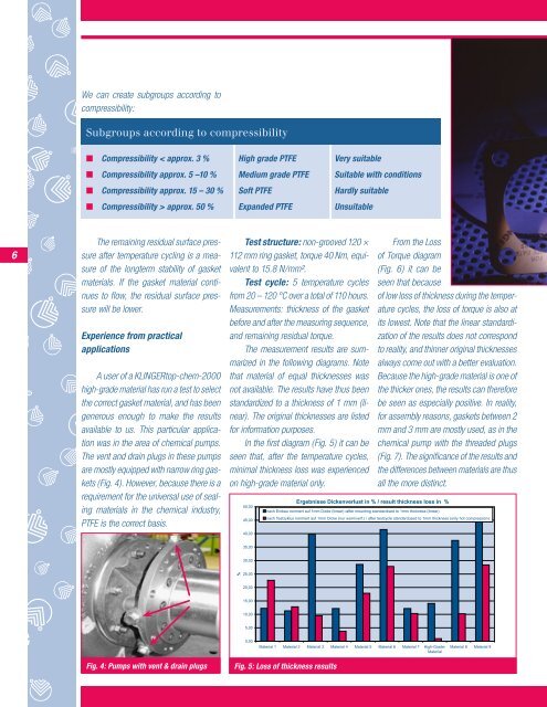
We can create subgroups according <strong>to</strong>compressibility:Subgroups according <strong>to</strong> compressibilityn Compressibility < approx. 3 % High grade PTFE Very suitablen Compressibility approx. 5 –10 % Medium grade PTFE Suitable with conditionsn Compressibility approx. 15 – 30 % Soft PTFE Hardly suitablen Compressibility > approx. 50 % Expanded PTFE Unsuitable6The remaining residual surface pressureafter temperature cycling is a measureof the longterm stability of gasketmaterials. If the gasket material continues<strong>to</strong> flow, the residual surface pressurewill be lower.PS10 solar power <strong>to</strong>werExperience from practicalapplicationsA user of a <strong>KLINGER</strong><strong>to</strong>p-chem-2000high-grade material has run a test <strong>to</strong> selectthe correct gasket material, and has beengenerous enough <strong>to</strong> make the resultsavailable <strong>to</strong> us. This particular applicationwas in the area of chemical pumps.The vent and drain plugs in these pumpsare mostly equipped with narrow ring gaskets(Fig. 4). However, because there is arequirement for the universal use of sealingmaterials in the chemical industry,PTFE is the correct basis.Test structure: non-grooved 120 ×112 mm ring gasket, <strong>to</strong>rque 40 Nm, equivalent<strong>to</strong> 15.8 N/mm².Test cycle: 5 temperature cyclesfrom 20 – 120 °C over a <strong>to</strong>tal of 110 hours.Measurements: thickness of the gasketbefore and after the measuring sequence,and remaining residual <strong>to</strong>rque.The measurement results are summarizedin the following diagrams. Notethat material of equal thicknesses wasnot available. The results have thus beenstandardized <strong>to</strong> a thickness of 1 mm (linear).The original thicknesses are listedfor information purposes.In the first diagram (Fig. 5) it can beseen that, after the temperature cycles,minimal thickness loss was experiencedon high-grade material only.50,0045,0040,00From the Lossof Torque diagram(Fig. 6) it can beseen that becauseof low loss of thickness during the temperaturecycles, the loss of <strong>to</strong>rque is also atits lowest. Note that the linear standardizationof the results does not correspond<strong>to</strong> reality, and thinner original thicknessesalways come out with a better evaluation.Because the high-grade material is one ofthe thicker ones, the results can thereforebe seen as especially positive. In reality,for assembly reasons, gaskets between 2mm and 3 mm are mostly used, as in thechemical pump with the threaded plugs(Fig. 7). The significance of the results andthe differences between materials are thusall the more distinct.Ergebnisse Dickenverlust in % / result thickness loss in %nach Einbau normiert auf 1mm Dicke (linear) /after mounting standardised <strong>to</strong> 1mm thickness (linear)nach Testzyklus normiert auf 1mm Dicke (nur warmverf.) / after testcycle standardused <strong>to</strong> 1mm thickness (only hot compression)35,0030,00%25,0020,0015,0010,005,000,00Material 1 Material 2 Material 3 Material 4 Material 5 Material 6 Material 7 High-Grade-MaterialMaterial 8 Material 9Fig. 4: Pumps with vent & drain plugsFig. 5: Loss of thickness results70,00Verlust an Drehmoment, normiert auf 1 mm Dicke (linear) /loss of <strong>to</strong>rque, standardised <strong>to</strong> 1 mm thickness (linear)60,00