PDF Koganei Solenoid Valves 040 Series - United Automation
PDF Koganei Solenoid Valves 040 Series - United Automation
PDF Koganei Solenoid Valves 040 Series - United Automation

You also want an ePaper? Increase the reach of your titles
YUMPU automatically turns print PDFs into web optimized ePapers that Google loves.
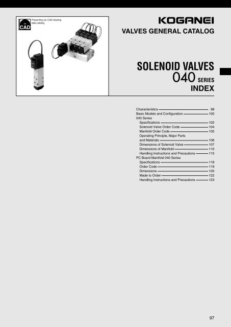
Presenting our CAD drawingdata catalogVALVES GENERAL CATALOGSOLENOID VALVESSERIESINDEXCharacteristics 98Basic Models and Configuration 100<strong>040</strong> <strong>Series</strong>Specifications 102<strong>Solenoid</strong> Valve Order Code 104Manifold Order Code 105Operating Principle, Major Partsand Materials 106Dimensions of <strong>Solenoid</strong> Valve 107Dimensions of Manifold 110Handling Instructions and Precautions 115PC Board Manifold <strong>040</strong> <strong>Series</strong>Specifications 118Order Code 119Dimensions 120Made to Order 122Handling Instructions and Precautions 12397
POWERFUL & LOW POWER CONSUMPTIONSOLENOID VALVESThe solenoid valve <strong>040</strong> series achieves its highly reliable, powerful and low current basicperformance into a thin body with valve width of 10mm.These reliable 2-, 3-, 5-port pilot type solenoid valve has features of flywheel diodes for surgesuppression as standard equipment.Moreover, the <strong>040</strong> series line-up features detailed improvements in utility, including an AJ typemanifold that offers excellent ease of assembly and maintenance, a twin solenoid whose length,wiring, and piping are the same as the single solenoid while maintaining functions of a doublesolenoid, and a PC board manifold containing a print circuit board with connector.SOLENOID VALVES <strong>040</strong> SERIESSERIES Pilot type solenoidvalve 2-, 3-, 5-port Effective area1.5mm 2 Power consumption0.7WOptimum for operation of 625 double acting and single actingcylinders, pilot-operated valves and actuators, etc.98
PC BOARD MANIFOLD <strong>040</strong> SERIESPilot type solenoidvalve2-, 3-, 5-portEffective area 1.5 Power consumption0.7WOnly available for8 stations and16 stations.SOLENOID VALVES <strong>040</strong> SERIESTWIN SOLENOID VALVES <strong>040</strong> SERIESNew space-saving type valve is installable with the solenoid valve <strong>040</strong> seriesand the <strong>040</strong> series PC board manifold.Retains the basic performance and functions of a double solenoid while alsoachieving the piping and wiring configuration of a single solenoid.Pilot type solenoidvalve5-portEffective area 1.5 Power consumption0.7W99
Basic Models and Configuration of <strong>040</strong> <strong>Series</strong>Single unitPilot type solenoid valve<strong>040</strong> series2-, 3-port 5-port, 2-positionNormallyclosed (NC)Normallyopen (NO)Single solenoidDouble solenoidTwin solenoidDirect piping041E1Note(<strong>040</strong>E1 )041E1-11(<strong>040</strong>E1-11Note)<strong>040</strong>-4E1<strong>040</strong>-4E2<strong>040</strong>-4KE2NoteNormallyclosed (NC)Normallyopen (NO)Single solenoidDouble solenoidSub-base pipingA041E1-25A041E1-11-25A<strong>040</strong>-4E1-25A<strong>040</strong>-4E2-25Note: The <strong>040</strong>E1, A<strong>040</strong>E1, and <strong>040</strong>-4KE2, A<strong>040</strong>-4KE2 are for manifolds for combined mounting of 2-, 3-, 5-port valves. They cannot be used as a single unit.When using 2-, 3-port valves as a single unit, please use 041E1, A041E1-25.100
Manifold<strong>040</strong> seriesSmall sized manifold for 2-, 3-port valve041MF—F type (P, R) manifold041E1041E1-11RP041MA—A type (all port)manifoldA041E1A041E1-11RPA041MAJ— AJ type (all port, with quick fitting)manifoldA041E1A041E1-11RPAquick fittingSOLENOID VALVES <strong>040</strong> SERIES<strong>040</strong>MF—F type (P, R) manifold<strong>040</strong>-4E2<strong>040</strong>-4E1<strong>040</strong>MA—A type (all port)manifoldA<strong>040</strong>-4E2A<strong>040</strong>-4E1<strong>040</strong>MAJ— AJ type (all port, with quick fitting)manifoldA<strong>040</strong>-4E2A<strong>040</strong>-4E1<strong>040</strong>E1, <strong>040</strong>E1-112-, 3-port valvefor manifold onlyA<strong>040</strong>E1, A<strong>040</strong>E1-112-, 3-port valvefor manifold only A<strong>040</strong>E1,A<strong>040</strong>E1-112-, 3-port valvefor manifold onlyManifold for combined mounting for 2-, 3-, 5-port valvePC board manifold Note35 (R)1 (P)<strong>040</strong>MFP—F type (P, R) manifold<strong>040</strong>E1, <strong>040</strong>E1-112-, 3-port valve for manifold only<strong>040</strong>-4E1<strong>040</strong>-4E235 (R)1 (P)35 (R)1 (P)4 (A)2 (B)<strong>040</strong>MAP—A type (all port) manifoldA<strong>040</strong>E1, A<strong>040</strong>E1-112-, 3-port valve for manifold onlyA<strong>040</strong>-4E1A<strong>040</strong>-4E235 (R)1 (P)4 (A)2 (B)35 (R)1 (P)2 (B)4 (A)Twin solenoid valve<strong>040</strong>MF—F type (P, R) manifold<strong>040</strong>E1,<strong>040</strong>E1-112-, 3-port valvefor manifold only<strong>040</strong>-4E1<strong>040</strong>-4KE2Twin solenoid valvefor manifold only35 (R)1 (P)<strong>040</strong>MA—A type (all port)manifoldA<strong>040</strong>E1,A<strong>040</strong>E1-112-, 3-port valvefor manifold onlyA<strong>040</strong>-4KE2Twin solenoid valve for manifold only35 (R)1 (P)4 (A)2 (B)<strong>040</strong>MAJ—AJ type (all port, with quick fitting)manifoldA<strong>040</strong>E1, A<strong>040</strong>E1-112-, 3-port valvefor manifold onlyA<strong>040</strong>-4E1A<strong>040</strong>-4KE2Twin solenoid valve for manifold only35 (R)1 (P)4 (A)2 (B)Note: Only available for 8 stations or 16 stations.101
SOLENOID VALVES<strong>040</strong> SERIESBasic Models and Valve FunctionsBasic modelDirect piping,F type manifold041E1(<strong>040</strong>E1 Note )<strong>040</strong>-4E1<strong>040</strong>-4E2<strong>040</strong>-4KE2 NoteCylinder operating speedHow to obtain cylinder speedItemNumber of positionsNumber of ports 2, 3 ports 5 portsValve functionItemMediaBasic modelOperation methodPort size Note 2Shock resistance m/s 2 {G} 1373.0 {140.0} (axial direction 245.0 {25.0})Operating voltage rangeWiring NoteColor of lead wireStandardOptionDC VCurrentmA(Power consumption whenrated voltage is applied: W)Surge suppression (as standard)4.55.5(510%)120 (0.6)With LED indicator121 (0.6)Green (+)Black (–)5.46.6(610%)105 (0.6)With LED indicator106 (0.6)Blue (+)Black (–)Grommet typePlug connector typeFlywheel diode10.813.2(1210%)55 (0.7)With LED indicator56 (0.7)Brown (+)Black (–)21.626.4(2410%)28 (0.7)With LED indicator29 (0.7)Maximum allowable leakage current mA 10 7 5 2Insulation resistance MΩ Min. 100Lead wire length NoteColor of LED indicatorSub-base piping,A, AJ type manifoldDirect piping,F type manifoldSub-base piping,A, AJ type manifoldMax. 12/18Max. 12/18With built-in flywheel diode for surge suppression300mmRedM30.5Operating pressure range MPa {kgf/cm 2 } 0.20.7 {2.07.1}Response time Note 3 DC5V, DC12VON/OFFmsDC6V, DC24VA041E1(A<strong>040</strong>E1 Note )Normally closed(NC, standard) orNormally open (NO, option)Singlesolenoid2 positionsDoublesolenoidMinimum time to energize for self holding ms 501212TwinsolenoidRemark: For optional specifications and order code, see p. 104105.Note: The <strong>040</strong>E1, A<strong>040</strong>E1, and <strong>040</strong>-4KE2, A<strong>040</strong>-4KE2 are manifolds for combined mounting of 2-, 3-, 5-port valves.They cannot be used as a single unit. When using 2-, 3-port valves as a single unit, please use041E1, A041E1-25.SpecificationsNotes: 1. For details, see the effective area on p. 103.2. For details, see the port size on p. 103.3. Values when air pressure is 0.5MPa {5.1kgf/cm 2 }.Values of <strong>040</strong>-4E2 and <strong>040</strong>-4KE2 are switching from the opposite position.Remark: Conversion to psi., 1MPa=145psi., 1kgf/cm 2 =14.2psi., e.g. 0.2MPa=29psi.Note: See made to order on p. 105.A<strong>040</strong>-4E1Effective areaCv Note 1 mm 2 1.50.08LubricationAirA<strong>040</strong>-4E2Internal pilot typeNot requiredProof pressure MPa {kgf/cm 2 } 1.05 {10.7}Maximum operating frequency Hz 5Operating temperature rangeatmosphere and mediaMounting direction<strong>Solenoid</strong> SpecificationsItemRated voltage°C041E1(<strong>040</strong>E1)A041E1(A<strong>040</strong>E1)<strong>040</strong>-4E1A<strong>040</strong>-4E1550Any<strong>040</strong>-4E2A<strong>040</strong>-4E2A<strong>040</strong>-4KE2 Note<strong>040</strong>-4KE2A<strong>040</strong>-4KE2Max. 12Max. 12DC 5V DC 6V DC 12V DC 24V Red (+)Black (–)Cylinder stroke<strong>Solenoid</strong> valveenergizedTo obtain the time required for the cylinder tocomplete 1 stroke, add cylinder's delay time, t1(time between energizing of solenoid valve andactual starting of cylinder), to the cylinder’smax. operating time, t2.When a cushion is used, add the cushioningtime, t3, to the above calculation. Standardcushioning time t3 is approximately 0.2 seconds.<strong>040</strong>-4E1Measurement conditions Air pressure: 0.5MPa {5.1kgf/cm 2 } Piping inner diameter and length: 2.51000mm Fitting: Barb fitting BF4BU-M3Load Load ratio = (%)Cylinder theoretical thrust Cylinder stroke: 60mm (10, 16)100 mm (20 32)LoadMaximum operating speed Maximum operating speedDelay timeDelay timeS 1.00.90.80.70.60.50.40.30.20.10t1 t2 t3Cylinder startCushioning impactCylinder stop<strong>Solenoid</strong> valve <strong>040</strong>-4E10.5MPaTimeFitting BF4BU-M3 Load ratio10 20 30 40 50 60 70Load ratio %102
Flow Rate Effective AreaCv mm 2MPa0.70.60.50.40.30.20.10Valve outlet pressure0.10.20.30.40.5Supply pressure(MPa)0.70.630 60 90 120 150Flow rate R/min(ANR)041E1(<strong>040</strong>E1)<strong>040</strong>-4E1<strong>040</strong>-4E2<strong>040</strong>-4KE2A041E1(A<strong>040</strong>E1)A<strong>040</strong>-4E1A<strong>040</strong>-4E2A<strong>040</strong>-4KE2How to read the graphIf supply pressure is 0.5MPa and flow is75R/min (ANR), the valve outlet pressurebecomes 0.4 MPa.Basic model Standard (single valve) Remarks041E1(<strong>040</strong>E1)<strong>040</strong>-4E1<strong>040</strong>-4E2<strong>040</strong>-4KE2A041E1(A<strong>040</strong>E1)A<strong>040</strong>-4E1A<strong>040</strong>-4E2A<strong>040</strong>-4KE2Basic model Port Port specifications Port size041E1(<strong>040</strong>E1 Note )<strong>040</strong>-4E1<strong>040</strong>-4E2<strong>040</strong>-4KE21.50.081.50.08<strong>Solenoid</strong> Valve Port SizeA041E1-25A<strong>040</strong>-4E1-25A<strong>040</strong>-4E2-25P, A, RP, A, B, RPA, BRPR When the quick fitting TS3-M3M is installed to P, A, B ports,the value becomes 0.750.04. When the quick fitting TS3-M3M is installed to P, A, B portson F type manifold, the value becomes 0.800.05. When the quick fitting TS4-M5M is installed to P, A, B portson A type manifold, the value becomes 1.300.07.FemalethreadFemalethreadFemalethreadM30.5M30.5M50.8Note: <strong>040</strong>E1 is dedicated valve for manifold. Cannot be connected to the P port with fitting.SOLENOID VALVES <strong>040</strong> SERIESManifold Connection Port SizeManifold model Port Location of piping connection Port size041MF<strong>040</strong>MF041MA<strong>040</strong>MA041MAJ<strong>040</strong>MAJPA, BRPA, BRPRPA, BRPRManifoldValveManifoldManifoldManifoldM50.8M30.5Rc1/8Rc1/8M50.8Rc1/8(Common for R, PR)Rc1/8Quick fitting for 4Rc1/8(Common for R, PR)Valve MassBasic model041E1(<strong>040</strong>E1)<strong>040</strong>-4E1<strong>040</strong>-4E2<strong>040</strong>-4KE2A041E1(A<strong>040</strong>E1)A<strong>040</strong>-4E1A<strong>040</strong>-4E2A<strong>040</strong>-4KE2Mass202222374521 (38)2222 (45)37 (60)45Remark: Figures in parentheses ( ) arethe mass with sub-base: -25.gManifold MassManifold model041MF041MA041MAJ<strong>040</strong>MF<strong>040</strong>MA<strong>040</strong>MAJMass calculation ofeach unitn=number of unitsBlock-offplateg103
Dimensions of <strong>Solenoid</strong> Valve for 2-, 3-port (Scale 3/4, Unit mm)041E110300 19.6041E1Manual overridePR3-M30.551.12-2.1Mounting hole30.29 5.9A13.38.57.7RP10.1 6.4A041E1-257.422-2.1 Counter bore 3.2 Depth 1Mounting hole56PR10.751402.A041E1-25A041E1SOLENOID VALVES <strong>040</strong> SERIES1714.3 2.730035.1Manual override110619.6 14.5523.1PRA8141730.222.62851.14-M50.82.752-3.1149.5Mounting hole29.5OptionsMade to OrderMuffler: -75For direct pipingOrder code for soldseparately: KM-032.5 126<strong>040</strong>MUFFMounting base: -2156.15To the top of the valveA1.2Locking type manualoverride: -81M30.5For sub-base pipingOrder code for soldseparately: KM-052-3.5143.5 14Mounting hole M50.8For wiring options and made to order, see p. 109.8107
17Manual override114.3 2.710 630019.63 5 Dimensions of <strong>Solenoid</strong> Valve 5-port , 2-position (Scale 3/4, Unit mm)<strong>040</strong>-4E1<strong>040</strong>-4E1Manual override5-M30.52-2.1Mounting hole 2-2.1 Counter bore 3.2 Depth 1Mounting holeA<strong>040</strong>-4E1-25A<strong>040</strong>-4E136.6161154 A58.5154.837.629.635 23.5PRP2012.32 B5-M50.83.72.7R59.917.527.52-3.1Mounting hole14101131OptionsMade to OrderMuffler: -75For direct pipingOrder code for soldseparately: KM-032.5 126<strong>040</strong>MUFFMounting base: -2156.15To the top of the valveA1.2Locking type manualoverride: -81M30.5For sub-base pipingOrder code for soldseparately: KM-053.5 142-3.5Mounting hole14 108M50.88
172.730036.62-Manual override110619.61611520.1PR4 AP3 5 Dimensions of <strong>Solenoid</strong> Valve 5-port , 2-position (Scale 3/4, Unit mm)<strong>040</strong>-4E2<strong>040</strong>-4E21030019.62-Manual override5-M30.52-2.1Mounting hole2-PR824120.14.8 4.8A<strong>040</strong>-4E2-254A2B2 27.43.2 3.22-2.1 Counter bore 3.2 Depth 1Mounting hole143.2 3.22.95R11P3R26.4 6.4A<strong>040</strong>-4E2SOLENOID VALVES <strong>040</strong> SERIES8229.6135R27.52012.32 B9.917.5412.755-M50.82-3.1Mounting hole10111431OptionsA<strong>040</strong>SOLMade to OrderA<strong>040</strong>SOL<strong>Solenoid</strong> with straightconnector: -PSL1024<strong>Solenoid</strong> with L connector: -PLL Grommet type with LED indicator: -LR 30R1630019.6ATotal length of valve27.5LED indicatorBTotal length of valve 21.5LED indicatorCTotal length of valveLED indicatorModel Code A B C R(Lead wire length) Remarks041E1,A041E1-25<strong>040</strong>-4E1,<strong>040</strong>-4KE2A<strong>040</strong>-4E1-25,A<strong>040</strong>-4KE2<strong>040</strong>-4E2,A<strong>040</strong>-4E2-2557.7 51.7 51.161.4 55.4 54.865.1 59.1 58.595.2 83.2 82-PSL,-PLL,-L: 300 (standard length)Made to order -1L: 1000, -3L: 3000Length to the end of the valve or sub-baseTotal length to the end of the opposite side solenoid109
Dimensions of Manifold for 2-, 3-port (Scale 3/4, Unit mm)041MFL3.5P3.513 10.2 10.2 1330037.6Manual override8 10 10 819.6178.52-3.3Mounting hole2-Rc1/8With 1 plug13.3M30.52stn.1 stn.2 stn.3 stn.4 stn.51432L4P430037.615.6 10.210.215.619.617Manual override10.6 10 10 10.610.68.54-Rc1/8With 2 plugs17.22232P10 14.5552.710.515.7R51.126.5RP5.5 12.52-M50.8With 1 plug041E1, 041E1-11Block-off plate-BPUnit dimensionsModel L P Model L P041M2F 36.2 29.2 041M12F 138.2 131.23F 46.4 39.4 13F 148.4 141.44F 56.6 49.6 14F 158.6 151.65F 66.8 59.8 15F 168.8 161.86F 77 70 16F 179 1727F 87.2 80.2 17F 189.2 182.28F 97.4 90.4 18F 199.4 192.49F 107.6 100.6 19F 209.6 202.610F 117.8 110.8 20F 219.8 212.811F 128 121 — — —041MA041MA3.9stn.1 stn.2 stn.3 stn.4 stn.52-3.3Mounting hole1432A041E1, A041E1-111106M50.8A17.6 10.2For wiring options and made to order, see p. 114.Block-off plate-BPUnit dimensionsModel L P Model L P041M2A 41.4 33.4 041M12A 143.4 135.43A 51.6 43.6 13A 153.6 145.64A 61.8 53.8 14A 163.8 155.85A 72 64 15A 174 1666A 82.2 74.2 16A 184.2 176.27A 92.4 84.4 17A 194.4 186.48A 102.6 94.6 18A 204.6 196.69A 112.8 104.8 19A 214.8 206.810A 123 115 20A 225 21711A 133.2 125.2 — — —
Dimensions of Manifold for 2-, 3-port (Scale 3/4, Unit mm)041MAJ041MAJL4P430037.615.6 10.210.215.619.617Manual override10.6 10 10 10.610.68.52-3.3Mounting hole4-Rc1/8With 2 plugs553.9Quick fitting66.7 17.22232stn.1 stn.2 stn.3 stn.4 stn.5A041E1, A041E1-11Block-off plate-BPA17.6 10.21409.041MAJ32RP10 14.5Unit dimensionsModel L P Model L P041M2AJ 41.4 33.4 041M12AJ 143.4 135.43AJ 51.6 43.6 13AJ 153.6 145.64AJ 61.8 53.8 14AJ 163.8 155.85AJ 72 64 15AJ 174 1666AJ 82.2 74.2 16AJ 184.2 176.27AJ 92.4 84.4 17AJ 194.4 186.48AJ 102.6 94.6 18AJ 204.6 196.69AJ 112.8 104.8 19AJ 214.8 206.810AJ 123 115 20AJ 225 21711AJ 133.2 125.2 — — —SOLENOID VALVES <strong>040</strong> SERIESFor wiring options and made to order, see p. 114.111
L4P430035.613.1 10.210.213.119.615Manual override2-3.3Mounting hole9.78242-Rc1/8With 1 plug6.410.60.811 12.52-M50.8With 1 plug2-3.3Mounting hole2854.81 5 Dimensions of Manifold for Combined Mounting of 2-, 3-, 5-port <strong>Valves</strong> (Scale 3/4, Unit mm)<strong>040</strong>MF<strong>040</strong>MF8.1 10 10 8.1A 4A 4A 4A2B 2B 2B16193082PR3M30.5222<strong>040</strong>-4E1<strong>040</strong>E1, <strong>040</strong>E1-11<strong>040</strong>-4E21430Block-off plate-BPstn.1 stn.2 stn.3 stn.4 stn.5Example of twin solenoid valve combined mounting112 For wiring options and made to order, see p. 114.Unit dimensionsModel L P Model L P<strong>040</strong>M2F 36.4 28.4 <strong>040</strong>M12F 138.4 130.43F 46.6 38.6 13F 148.6 140.64F 56.8 48.8 14F 158.8 150.85F 67 59 15F 169 1616F 77.2 69.2 16F 179.2 171.27F 87.4 79.4 17F 189.4 181.48F 97.6 89.6 18F 199.6 191.69F 107.8 99.8 19F 209.8 201.810F 118 110 20F 220 21211F 128.2 120.2 — — —
L4P430041.615.6 10.210.215.619.621Manual override10.6 1010 10.62-3.3Mounting hole1110234-Rc1/8613.16.22332213882R16 14.51 3 5 Dimensions of Manifold for Combined Mounting of 2-, 3-, 5-port <strong>Valves</strong> (Scale 3/4, Unit mm)<strong>040</strong>MA<strong>040</strong>MAWith 2 plugsPSOLENOID VALVES <strong>040</strong> SERIESA<strong>040</strong>-4E114A<strong>040</strong>E1,A<strong>040</strong>E1-11A<strong>040</strong>-4E236Plug to B for mounting A<strong>040</strong>E1Plug to A for mounting A<strong>040</strong>E1-11Block-off plate-BP2-M50.8for each unit2B9.564A12.<strong>040</strong>MA12.63 3stn.1 stn.2 stn.3 stn.4 stn.5Example of twin solenoid valve combined mountingL15.320.215.6 2-3.310 10.6Mounting hole6.2322338 2361For wiring options and made to order, see p. 114.Unit dimensionsModel L P Model L P<strong>040</strong>M2A 41.4 33.4 <strong>040</strong>M12A 143.4 135.43A 51.6 43.6 13A 153.6 145.64A 61.8 53.8 14A 163.8 155.85A 72 64 15A 174 1666A 82.2 74.2 16A 184.2 176.27A 92.4 84.4 17A 194.4 186.48A 102.6 94.6 18A 204.6 196.69A 112.8 104.8 19A 214.8 206.810A 123 115 20A 225 21711A 133.2 125.2 — — —113
4LP430043.615.6 10.210.215.619.623Manual override10.6 101010.64-3.3Mounting hole13 4-Rc1/811 With 2 plugs2.569823R235 2424P3214.51 Dimensions of Manifold for 5-port, 2-position (Scale 3/4, Unit mm)<strong>040</strong>MAJ<strong>040</strong>MAJ171314.274614A<strong>040</strong>-4E1A<strong>040</strong>E1, A<strong>040</strong>E1-112-Quick fittingfor each unitPlug to B for mounting A<strong>040</strong>E1Plug to A for mounting A<strong>040</strong>E1-1111612.63 3A<strong>040</strong>-4E2Block-off plate<strong>040</strong>M2AJ 41.4 33.4 <strong>040</strong>M12AJ 143.4 135.4-BP 3AJ 51.6 43.6 13AJ 153.6 145.64AJ 61.8 53.8 14AJ 163.8 155.85AJ 72 64 15AJ 174 1666AJ 82.2 74.2 16AJ 184.2 176.22B7AJ8AJ92.4102.684.494.617AJ 194.4 186.418AJ 204.6 196.64A9AJ 112.8 104.8 19AJ 214.8 206.810AJ 123 115 20AJ 225 21711AJ 133.2 125.2 — — —38Unit dimensionsModel L P Model L Pstn.1 stn.2 stn.3 stn.4 stn.5Combined mounting of twin solenoid valve is acceptable. See p. 112.OptionsA<strong>040</strong>SOLMade to OrderA<strong>040</strong>SOL<strong>Solenoid</strong> with straightconnector: -PSL<strong>Solenoid</strong> with L connector: -PLL Grommet type with LED indicator: -L1024RR 301630019.6ATotal length of valve27.5LED indicatorBTotal length of valve 21.5LED indicatorCTotal length of valveLED indicatorModel041E1, A041E1<strong>040</strong>E1, A<strong>040</strong>E1, <strong>040</strong>-4E1, A<strong>040</strong>-4E1 ,<strong>040</strong>-4KE2, A<strong>040</strong>-4KE2<strong>040</strong>-4E2, A<strong>040</strong>-4E2114Code A B C RLead wire length) Remarks57.7 51.7 51.161.4 55.4 54.895.2 83.2 82-PSL, -PLL, -L: 300 (standard length)Made to order -1L: 1000, -3L: 3000Length to the end of the valveTotal length to the end of the opposite side solenoid
Handling Instructions and Precautions<strong>Solenoid</strong>Plug connectorManual overrideInternal circuitAttaching and removing plug connectorNon-lock typeDC5V, DC6V, DC12V, DC24VStandard solenoid (surge suppression)Lead wire DC5V Green Short circuit protection diodeDC6V BlueDC12VBrownDC24VRed<strong>Solenoid</strong>FlywheeldiodeLead wire: Black<strong>Solenoid</strong> with LED indicator (surgesuppression)Order code-PSL, -PLLLead wire DC5V GreenDC6V BlueDC12VBrownDC24VRedLED indicatorLight emitting diodeUse fingers to insert the connector into thepin, push in until the lever claw catches on theconvex section on the connector housing, andcomplete the connection.To remove the connector, squeeze the leveralong with the connector, lift the lever claw upfrom the convex section on the connectorhousing, and pull out.Convex sectionPinConnector housingLeverIndication of polarityDCConnectorContactConnector assemblyTo operate, press the manual override all theway down. The valve works the same as anenergized state as long as the manual override ispushed down, and returns to the rest positionupon release.In the double solenoid and twin solenoid,pressing the manual override on the S1 (S2) sideswitches the state of the S1 (S2) to energizedstate, and the unit remains in that state evenafter the manual override is released. To returnto the rest position, operate the manual overrideon the S2 (S1) side.SOLENOID VALVES <strong>040</strong> SERIESLead wire: BlackLED indicator: RedIllustration shows the110 series.CThe PC board manifold is DC24V only.Crimping of connecting lead wire and contactCautions: 1. Do not apply megger between thelead wires.2. While there is no danger with a DCsolenoid of a short circuit due to thewrong polarity, the valve will notoperate.3. Leakage current inside the circuitcould result in failure of the solenoidvalve to return or in other erraticoperation. Always use within therange of the allowable leakagecurrent. If circuit conditions, etc.,cause the leakage current to exceedthe maximum allowable leakagecurrent, consult us.4. For double solenoid and twin solenoid,avoid energizing both solenoidssimultaneously. The valve could fallinto a neutral state.To crimp lead wires into contacts, strip off 4mm of the insulation from the tip of the leadwire, insert into the contact, and crimp it. Besure at this time to avoid catching theinsulation on the wire as crimping section.ContactHookExpose wirecrimping sectionExpose wire 4mmLead wireEquivalent toAWG2226Insulation crimp tabInsulationMaximum outerdiameter1.7Cautions: 1. Do not pull hard on the lead wire.2. Always use the dedicated tool forcrimping of connecting lead wireand contact.Contact: Model 702062-2MManufactured by Sumiko Tech, Inc.Crimping tool: Model F1-702062Manufactured by Sumiko Tech, Inc.Lock typeTo lock the manual override, use a smallscrewdriver to push down on the manualoverride all the way down and turn it clockwise45 degrees. When locked, turning the manualoverride 45 degrees in a counterclockwisedirection returns it to its original position, andreleases the lock.Attaching and removing contact and connectorInsert the contact with lead wire into a plugconnector hole until the contact hookcatches and is secured to the plugconnector. Confirm that the lead wire cannotbe easily pulled out.To remove, insert a tool with a fine tip (suchas a small screwdriver) into the rectangularhole on the side of the plug connector topush up on the hook, and then pull out thelead wire.Illustration shows the 240 series.Cautions: 1. The <strong>040</strong> series are pilot type solenoidvalves. As the result, the manualoverride cannot switch the main valvewithout supplying air from the P port.2. Always release the lock on thelocking type before commencingnormal operation.3. Do not attempt to operate the manualoverride with a pin or other objecthaving an extremely fine tip. It coulddamage the manual override button.Cautions: 1. Do not pull hard on the lead wire. Itcould result in defective contacts,breaking wires, etc.2. If the pin is bent, use a smallscrewdriver, etc., to gentlystraighten out the pin, and thencomplete the connection to the plugconnector.115
FittingRecommended fittings041E1PartsPortA port P, R port Note 1 P port Note 2 R portQuick fittingTS3-M3MTL3-M3MTLL3-M3MTS3-M3MTL3-M3MTLL3-M3MTS3-M3M —TAC fittingFor urethane tubeFor nylon tubeBF4BU-M3BF3BU-M3BF4-M3BF3.2-M3BF4BU-M3BF3BU-M3BF4-M3BF3.2-M3BF4BU-M3BF3BU-M3BF4-M3BF3.2-M3Muffler — — — KM-03—<strong>040</strong>-4E1, <strong>040</strong>-4E2, <strong>040</strong>-4KE2PartsPortA, B port P, R port Note 1 P port Note 2 R portQuick fittingTS3-M3MTS3-M3MTL3-M3MTLL3-M3MTS3-M3M —TAC fittingFor urethane tubeFor nylon tubeBF4BU-M3BF3BU-M3BF4-M3BF3.2-M3BF4BU-M3BF3BU-M3BF4-M3BF3.2-M3BF4BU-M3BF3BU-M3BF4-M3BF3.2-M3—— — KM-03Notes :1. For piping to the P port only, TSH4-M3M may also be used.2. These fittings may be used for mounting a muffler to the R port.—A041E1-25PartsPortA portP portR, PR portQuick fittingTS4-M50TS4-M5MTSH4-M5MTS4-M50TS4-M5MTSH4-M5MTS4-M50TS4-M5MTSH4-M5MMufflerSpeed controller reference)——KM-03150-30A— — SCE-M5A<strong>040</strong>-4E1-25, A<strong>040</strong>-4E2-25PartsPortA, B portP portR, PR portQuick fittingTS4-M50TSH4-M5TS4-M5MTSH4-M5MTS4-M50TSH4-M5TS4-M5MTSH4-M5MTS4-M50TSH4-M5TS4-M5MTSH4-M5MMuffler——KM-03150-30A116
117SOLENOID VALVES <strong>040</strong> SERIES
PC BOARD MANIFOLD<strong>040</strong> SERIESManifold Basic Models and SpecificationsItemBasic modelType ofmounting valveManifold functionNumber ofunits2-, 3-port8 stations16 stations5-port, single solenoid5-port, double solenoid5-port, twin solenoidP, R manifold<strong>040</strong>M8FP<strong>040</strong>M16FP<strong>040</strong>E1<strong>040</strong>-4E1<strong>040</strong>-4E2<strong>040</strong>-4KE2All port manifold<strong>040</strong>M8AP<strong>040</strong>M16APA<strong>040</strong>E1A<strong>040</strong>-4E1A<strong>040</strong>-4E2A<strong>040</strong>-4KE2WiringConnector type for flat cable (AWG28) Note 1 : With short clip (standard)With long clip (option) Note 2Common wiringOperating temperature range (atmosphere and media) °CShock resistancem/s 2 {G}Mounting directionItemMediaResponse time Note DC5V, DC12VmsON/OFF DC6V, DC24VTypeOperating voltage rangeWiringBasic modelOperation methodEffective areaCv mm 2LubricationOperating pressure range MPa {kgf/cm 2 }Proof pressure MPa {kgf/cm 2 }Maximum operating frequencyMinimum time to energize for self holdingColor of lead wireDC VCurrent(Power consumption when mArated voltage is applied: W)Maximum allowable leakage current mAInsulation resistanceColor of LED indicatorFor FP type manifoldFor AP type manifoldMΩHeaderBox type, with short clip(Product number3662-5002SCSC)Box type, with long clip(Product number: 3662-5002LCSC)HzmsDC5V<strong>040</strong>E1A<strong>040</strong>E1With built-in flywheel diode for surge suppression4.55.5(5±10%)130(0.7)Min. 100Plug connector type straight connector -PSL:With dedicated lead wire for PC board connection,with connectorRed (+), Black (–)RedSocket Note Strain relief Note StandardOpen end type,with nose(Product number:7910-6500SC)Plus common (standard)Minus common (option: -CM) Note550245.2 {25.0}Notes: 1. For details about specifications, see the specifications of connector for flat cable.2. For order codes, see p. 119.<strong>Solenoid</strong> Valve Specifications—Any<strong>040</strong>-4E1 <strong>040</strong>-4E2AirInternal pilot type1.50.08Not required0.20.7 {2.07.1}1.05 {10.7}Max. 12/1512 Max. 12Max. 12/15 12 Max. 125— 505.46.6(6±10%)115(0.7)10.813.2(12±10%)65(0.8)With attached(Product number3448-7910J)<strong>040</strong>-4KE2A<strong>040</strong>-4E1 A<strong>040</strong>-4E2 A<strong>040</strong>-KE2Note: Values when air pressure is 0.5MPa {5.1kgf/cm 2 }. Values of <strong>040</strong>-4E2 and<strong>040</strong>-4KE2 are switching from the opposite position.Remark: Conversion to psi., 1MPa=145psi., 1kgf/cm 2 =14.2psi., e.g. 0.2MPa=29psi.<strong>Solenoid</strong> SpecificationsItemOrder codeBlank-LCDC6V DC12V DC24V21.626.4(24±10%)40(1.0)10 7 5 2MIL-C-83503conformity(made bySumitomo 3M Ltd.)Remark: While the connector has a center slot (groove), note that it has no key grooves forprevention of erroneous insertion.Note Included at time of delivery.118ItemRated voltageSpecifications of Connector for Flat CableFlow RateManifold Connection Port SizeManifold model Port Location of piping connection Port size<strong>040</strong>MFP<strong>040</strong>MAPMassManifoldmodelMPa0.70.60.50.40.30.20.10Valve outlet pressure<strong>040</strong>M8FP 122<strong>040</strong>M16FP<strong>040</strong>M8AP<strong>040</strong>M16APHow to read the graphIf supply pressure is 0.5MPa and flowrate is 75R/min (ANR), the valve outletpressure becomes 0.4 MPa.ManifoldMass229217396PA, BRPA, BRPRSupply pressure(MPa)0.70.60.5<strong>040</strong>E10.4<strong>040</strong>-4E10.3<strong>040</strong>-4E2<strong>040</strong>-4KE20.2A<strong>040</strong>E10.1A<strong>040</strong>-4E1A<strong>040</strong>-4E2A<strong>040</strong>-4KE230 60 90 120 150Flow rate R/min(ANR)ManifoldValveManifoldManifoldMounting valve massM50.8M30.5Rc1/8Rc1/8M50.8Rc1/8(Common for R, PR)<strong>040</strong>E1 <strong>040</strong>-4E1 <strong>040</strong>-4E2 <strong>040</strong>-4KE2Block-offplate22 22 37 45 322 22 37 45 4g
PC Board Manifold <strong>040</strong> <strong>Series</strong> Order Code Common wiring Connector 2-, 3-port valveNumber of ports 2-, 3-port valveValve function WiringPlus commonWith short clip3-portNormally closedNCStraight connectorwith LED indicatorBlankBlankBlankBlank-PSL2-portNormally openNO-CM-LC-2-11SOLENOID VALVES <strong>040</strong> SERIESPC board manifoldfor combined mounting of 2-, 3-, 5-port valve<strong>040</strong>MManifold modelNumber of units816FP -CM -LCAP -CM -LCRemark: <strong>040</strong>E1 is 3-port, and normally closed (NC) as standard.Valve mounting location from the left-handside when facing A, B port (: 1 16)Since twin solenoid valve needs twostations per valve to mount, the secondstation (solenoid S1 side) should be blank.When selecting <strong>040</strong>-4E2, always enter-BP for the next station.Stationstn.stn.stn.stn.Basic model-<strong>040</strong>E1-2 -2-<strong>040</strong>-4E1-<strong>040</strong>-4E2-<strong>040</strong>-4KE2-A<strong>040</strong>E1-A<strong>040</strong>-4E1-A<strong>040</strong>-4E2-A<strong>040</strong>-4KE2-2-11-11-PSL-PSLSpecify the valve type for each station.Enter -BP when closing a station with a block-off platewithout mounting a valve.<strong>040</strong>-4E2 cannot be mounted to the last station.<strong>040</strong>-4KE2 cannot be assigned to the last stationwhen ordering.DC5VDC6VDC12VDC24VDC5VDC6VDC12VDC24VAdditional Parts (Sold Separately)Made to OrderFor details, see p. 122.Block-off plateAJP type manifoldAJP <strong>040</strong> M F -BPF—For FP type manifoldA—AP, AJP type manifold119
Dimensions (Scale 1/2, Unit mm)<strong>040</strong>M8FP<strong>040</strong>M16FP8.3 7 D 7 8.361.384.133.8Connector for flat cableWith short clip: StandardWith long clip: -LCL4P413.110.210.213.1438.1 1010 8.124 182Rc1/8With 1 plug13.8161P116.419304147.635R23.550 AM30.52 2 22-3.3Mounting hole112-M50.8With 1 plug041E1, 041E1-11 <strong>040</strong>-4E1 <strong>040</strong>-4E2Block-off plate-BPUnit dimensionsModel L P D<strong>040</strong>M8FP 97.6 89.6 67<strong>040</strong>M16FP 179.2 171.2 148.63Option dimensionsTypeShort clip 12.5Long clip 15.5AExample of twin solenoid valve combined mountingLP10.2 13.11048.12-3.3Mounting hole1.416304147.6120
Dimensions (Scale 1/2, Unit mm)<strong>040</strong>M8AP<strong>040</strong>M16AP10.8 7 D 7 10.868.879.136.3Only 16 stationsConnector for flat cableWith short clip: StandardWith long clip: -LC13.8410.615.6 10.210LP410.2 15.610 10.623193847.61P35R1630.558.5 SOLENOID VALVES <strong>040</strong> SERIES6.22-3.3Mounting hole13144Rc1/8Both sidesA041E1, A041E1-11 A<strong>040</strong>-4E1 A<strong>040</strong>-4E2Plug to B for mounting A<strong>040</strong>E1Plug to A for mounting A<strong>040</strong>E1-11Block-off plate-BPUnit dimensionsModel L P D<strong>040</strong>M8AP 102.6 94.6 67<strong>040</strong>M16AP 184.2 176.2 148.618.5933 32B4ATypeAShort clip 12.5Long clip 15.5Example of twin solenoid valve combined mountingLP10.2 15.610 10.62-3.3Mounting hole233847.6Option dimensions 121
Made to OrderA variety of made to order items are available to further expansionof the range of applications for the PC board manifolds compatiblewith the solenoid valve <strong>040</strong> series.Order Code<strong>040</strong>MAJP type manifoldVoltageType of mounting valveAJPNumber of unitsStationAJP type manifoldSpecificationsThe manifold, solenoid valve, and solenoid specifications arethe same as the AP type manifold specifications.See p. 118.Manifold Connection Port SizeManifold model<strong>040</strong>MAJPPortPA, BRPRLocation of piping connectionManifoldPiping sizeRc1/8Quick fitting for 4Rc1/8(R, PR common)Manifold MassManifold model<strong>040</strong>M16AJP<strong>040</strong> series manifoldRemarks 1. For the type of mounting valve, see p. 119.2. The order code for the block-off plate sold separately is<strong>040</strong>MA-BP.Manifold Mass<strong>040</strong>M8AJP 305560<strong>040</strong>E122<strong>040</strong>-4E122<strong>040</strong>-4E237<strong>040</strong>-4KE245Block-off plate4gDimensions (Scale 1/2, Unit mm)<strong>040</strong>M8AJP<strong>040</strong>M16AJP10.8 7 D 7 10.868.8 79.1Only 16 stations36.3Unit dimensionsModel L P D<strong>040</strong>M8AJP 102.6 94.6 67<strong>040</strong>M16AJP 184.2 176.2 148.6Connector for flat cableWith short clip: StandardWith long clip: -LCOption dimensionsTypeAShort clip 12.5Long clip15.5L415.6 10.210.6 10P410.2 15.610 10.65124 2614.27242.513.82432464147.61P 35R38.566.5 A4-3.3Mounting hole144Rc1/8Both sides16A041E1, A041E1-11 A<strong>040</strong>-4E1 A<strong>040</strong>-4E22-quick fittingfor each unitPlug to B for mounting A<strong>040</strong>E1Plug to A for mounting A<strong>040</strong>E1-112BBlock-off plate-BP2094A12233 3
Handling Instructions and Precautions(PC Board Manifold)<strong>Solenoid</strong>Plug connectorManifoldCircuit configurationsAttaching and removing plug connectorPrint circuit board For plus common type (standard)Operation exampleLead wire: Red<strong>Solenoid</strong>q w iLead wire: BlackControl signal01 02 08Corresponding to sequencerOutput module is minus common type.q w e r t y u iUse fingers to insert the connector into thepin, push in until the lever claw catches onthe convex section on the connectorhousing, and complete the connection.To remove the connector, squeeze the leveralong with the connector, lift the lever clawup from the convex section on theconnector housing, and pull out.+ C –ConnectorLeverIndication of polarity+ C –Exclusive lead wire forPC board connectionConnector assemblyAvoid use in the locations listed below, as itmay result in deterioration of the print circuitboard or shorts in the wiring. If use in suchconditions is unavoidable, always provide acover or other adequate protectivemeasures.1. Locations subject to high levels of dust oroil mists.2. Locations subjected to salt, corrosivegases or conductive particles.3. Locations directly subject to condensation,direct sunlight or other weathereffects.SOLENOID VALVES <strong>040</strong> SERIESCOM 01 02 03 04 05 06 07 08Minus commonFor minus common typeoption: -CMOperation exampleLead wire: Black<strong>Solenoid</strong>qi: <strong>Solenoid</strong>0108:Sequencer outputterminalq w iConnector housingConvex sectionPinCautions: 1. Do not pull hard on the lead wire.Itcould result in defective contacts,shorted lines, etc.2. If the pin is bent, use a smallscrewdriver, etc., to gentlystraighten out the pin, and thencomplete the connection to the plugconnector.Lead wire: RedControl signal01 02 08Dedicated lead wire for PC board connectionCorresponding to sequencerOutput module is plus common type.q w e r t y u iCOM 01 02 03 04 05 06 07 08Plus commonCautions: 1. Do not apply megger between thelead wires.2. While there is no danger with a DCsolenoid of a short circuit due to thewrong polarity, the valve will notoperate.3. Leakage current inside the circuitcould result in failure of the solenoidvalve to return or in other erraticoperation. Always use within therange of the allowable leakagecurrent. If circuit conditions, etc.,cause the leakage current to exceedthe maximum allowable leakagecurrent, consult us.4. For double solenoid and twinsolenoid, avoid energizing bothsolenoids simultaneously. The valvecould fall into a neutral state.5. Ensure that voltage drops due toresistance in the cable used remainswithin the voltage range for thesolenoid valve.If the supplied voltage fails to reachthe minimum required voltage, thevalve could fail to operate properly.Order code by one unitForstandardFor-CM(Number of wires to use)Order code <strong>040</strong>E1 <strong>040</strong>-4E1 <strong>040</strong>-4E2 <strong>040</strong>-4KE2Y160208 1 1 1 2Y160209 Note 0 0 1 0Y160225 1 1 1 2Y160226 Note 0 0 1 0Note: Y160209 and Y160226 are for dedicated leadwires for double solenoid (solenoid S1 side).Connector for flat cableqi: <strong>Solenoid</strong>0108:Sequencer outputterminal Product number HeaderClipMIL-C-83503 conformity(Made by Sumitomo 3M Ltd.)Triangle mark(First contact pin indication)SocketFlat cable(Equivalent to AWG 28:MAX. 10m)123
Combined mounting for different type of valvesIn the <strong>040</strong> <strong>Series</strong> manifold for combinedmounting of 2-, 3-, 5-port valves and PC boardmanifold for combined mounting of 2-, 3-, 5-port valves, single solenoids may be combinedwith double solenoids, or with twin solenoids,and a total number of up to 8 or 16 solenoidscan be mounted.In this case, observe the following precautions.1. Always use a block-off plate (-BP) to closethe right station (the side with the highernumbered station) of the station where thedouble solenoid valve is mounted.2. If using block-off plates (-BP) for somereason other than the above Item 1, placethem on the higher numbered stations side.3. Connector pin numbers are allocated tostations in order from the left end of themanifold. For a double solenoid mounting,the upper pins are allocated to S2 and thelower ones to S1, with the upper S2numbers being allocated the smaller pinnumbers. And for a twin solenoid mounting,the left side is allocated to S2 and the rightside to S1, with the left-side S2 numbersbeing the smaller pin numbers.Example of an 8 units manifold, with 4 singlesolenoid valves and 2 double solenoid valvesmountedq w e r tS2uS2stn.1 stn.2 stn.3 stn.4 stn.5stn.6 stn.7 stn.8S1yS1iConnector pin locations for 8 unitsCOM.uit e qy r wRemark: The standard is plus common wiring.Minus common wiring is optional (-CM).Example of an 8 units manifold, with 3 singlesolenoid valves and 2 double solenoid valvesmountedq w e r t y uS2 S1 S2 S1stn.1 stn.2stn.3 stn.4 stn.6 stn.8Connector pin locations for 8 unitsCOM.u t e qy r wRemark: The standard is plus common wiring.Minus common wiring is optional (-CM).124