Create successful ePaper yourself
Turn your PDF publications into a flip-book with our unique Google optimized e-Paper software.
CAD drawing data catalogis available.VALVES GENERAL CATALOGSOLENOID VALVES, , SERIESINDEXFeatures 725Basic Models and Configuration 727Operating Principles 728<strong>430</strong> <strong>Series</strong>Specifications 729<strong>Solenoid</strong> <strong>Valve</strong> Order Codes 731Collective Wiring Manifold Order Codes 732Individual Wiring Manifold Order Codes 733Operating Principles, Major Parts and Materials 734Dimensions of <strong>Solenoid</strong> <strong>Valve</strong> 735Dimensions of Collective Wiring Manifold 737Dimensions of Individual Wiring Manifold 739630 <strong>Series</strong>Specifications 741<strong>Solenoid</strong> <strong>Valve</strong> Order Codes 743Collective Wiring Manifold Order Codes 744Individual Wiring Manifold Order Codes 745Operating Principles, Major Parts and Materials 746Dimensions of <strong>Solenoid</strong> <strong>Valve</strong> 747Dimensions of Collective Wiring Manifold 749Dimensions of Individual Wiring Manifold 751830 <strong>Series</strong>Specifications 753<strong>Solenoid</strong> <strong>Valve</strong> Order Codes 755Operating Principles, Major Parts and Materials 756Dimensions of <strong>Solenoid</strong> <strong>Valve</strong> 757Made to Order 759Handling Instructions and Precautions 761SOLENOID VALVES <strong>430</strong>, 630, 830 SERIESCautionBefore use, be sure to read the “Safety Precautions” on p. 31.724
Pilot type solenoid valves<strong>Solenoid</strong> <strong>Valve</strong>s, ,<strong>Series</strong>Compact DesignClean lines due to a compact body, and the lead wiresconnecting to the terminal block on the sub-base or manifoldenable collective wiring for simplified wiring work. A design thatfits well with compact units.Quick Installation and Removal of <strong>Valve</strong>sA simple plug-in wiring system is used for connections between asolenoid valve and its sub-base, and solenoid valves and amanifold base. <strong>Valve</strong>s can be replaced without disturbing wiringor piping.Non-Neutral StructureUses a non-neutral structure to eliminate unstable operationarisen during flow direction changes in large valves.Long LifeWear resistance of lip seals is improved for further durability.Safe WiringBridge diodes are used for the DC24V specification internalcircuits. As with AC types, wiring can be performed withoutconcern for polarity.725
Saves on Wiring (<strong>430</strong>, 630 series only)Comes with multi-connector system for collective electricalwiring, or with rational and compatible D-sub connector. Bothtypes include pre-wired common systems to save time in wiringwork.Conforming SerialTransmission Systems(<strong>430</strong> series only)Greatly reduces manhours required for wiring, and achieves costreduction considering all factors in a pneumatic control systemthrough prevention of wrong wiring, offering easier maintenance,etc.Computerfor FAComputer link lineMulti connector assembly(To be ordered separately)D-sub connector assembly(To be ordered separately)Easy Increase or Decrease ofManifold Units (<strong>430</strong>, 630 series only)Since the manifold base is structurally independent fromsolenoid valves, increase or decrease of units is simple. It is alsopossible to stock the manifold bases as a single unit. Use of portisolators enables the supply of 2 different pressures on a singlemanifold.ProgrammablecontrollerRemote I/Omain stationSerialtransmission lineUpper link unitRemote I/O sub-stationI/O unitsRemote I/O sub-stationVarious remote unitsElectric equipmentElectric equipmentRemote I/O sub-station for manifold use solenoid valve<strong>Solenoid</strong>valve of <strong>430</strong> seriesfor serial transmissionPneumatic equipmentSOLENOID VALVES <strong>430</strong>, 630, 830 SERIESIndividual Wiring Manifold(<strong>430</strong>, 630 series only)Individual wiring is in each station. Comes with grommetterminal, conduit terminal and DIN connector. Select the choiceof the wiring type.Bottom Piping (made to order)Depending on the installation requirements, piping direction canbe selected from either the side or bottom surface.External Pilot (made to order)Offers stable switching from low to high pressure (00.9MPa{09.2kgf/cm 2 } [0131psi.]).726
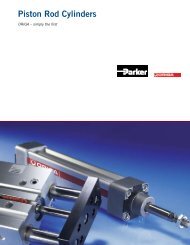
Basic Models and Configuration<strong>Solenoid</strong> valvesseriesSub-base5-port, 2-, 3-positionEffective area2-position type : 40mm 2 /35mm 2 Cv : 2.2/1.93-position type : 35mm 2 /30mm 2 Cv : 1.9/1.7Applicable cylinder bore sizes :50 [1.969in.] 125 [4.921in.]5-port, 2-positionsingle solenoid5-port, 2-positiondouble solenoid5-port, 3-positiondouble solenoidManifoldA type (all ports) manifold<strong>430</strong>M <strong>430</strong>-4E1 <strong>430</strong>-4E2 433-4E2<strong>Solenoid</strong> valvesseriesSub-base5-port, 2-, 3-positionEffective area2-position type : 60mm 2 /55mm 2 Cv : 3.3/3.13-position type : 50mm 2 /45mm 2 Cv : 2.8/2.5Applicable cylinder bore sizes :100 [3.937in.]180 [7.087in.]5-port, 2-positionsingle solenoid5-port, 2-positiondouble solenoid5-port, 3-positiondouble solenoidManifoldA type (all ports) manifold630M 630-4E1630-4E2 633-4E2<strong>Solenoid</strong> valvesseriesSub-base5-port, 2-, 3-positionEffective area2-position type : 120mm 2 /100mm 2 Cv : 6.7/5.63-position type : 120mm 2 /100mm 2 Cv : 6.7/5.6Applicable cylinder bore sizes :125 [4.921in.]300 [11.811in.]5-port, 2-positionsingle solenoid5-port, 2-positiondouble solenoid5-port, 3-positiondouble solenoid830-4E1 830-4E2 833-4E2727
Operating Principles The operating principles below are for the 630 series.Basic modelEnergized state<strong>Solenoid</strong> OFF<strong>Solenoid</strong> ON2-position5-portsingle solenoidBasic modelEnergized state<strong>Solenoid</strong> 14(SA)OFF<strong>Solenoid</strong> 12(SB)OFF<strong>Solenoid</strong> 14(SA)ON<strong>Solenoid</strong> 12(SB)OFF<strong>Solenoid</strong> 14(SA)OFF<strong>Solenoid</strong> 12(SB)ON(De-energized condition after energizing solenoid SB)2-position5-portdouble solenoid5-portClosed centerSOLENOID VALVES <strong>430</strong>, 630, 830 SERIES3-position5-portExhaust center5-portPressure center728
SOLENOID VALVESSERIESBasic Models and <strong>Valve</strong> FunctionsItemNumber of positionsNumber of portsSpecificationsBasic model<strong>430</strong>-4E1 <strong>430</strong>-4E2 433-4E22 positions<strong>Valve</strong> function Remark: For optional specifications and order codes, see p.731733.ItemMediaOperation typeEffective area Note 1 mm 2CvLubricationOperating pressure rangePort size Note 2Response time Note 3ms DC24VON/OFF AC100V, AC200VMinimum time to energize for self holdingBasic modelMPa {kgf/cm 2 } [psi.] 0.20.9 {2.09.2} [29131]351.95 portsPilot typeShock resistance m/s 2 {G} 294 {30}ms3 positionsClosed center (standard)Exhaust center (optional)Pressure center (optional)<strong>430</strong>-4E1 <strong>430</strong>-4E2 433-4E2402.225/25 or below 20/20 or below 25/35 or below20/30 or below 15/15 or below 20/35 or belowNotes: 1. For details, see the effective area on p.730.2. For details, see the port size on p.730.3. Values when the air pressure is 0.5MPa {5.1kgf/cm 2 } [73psi.]. The values for <strong>430</strong>-4E2 are whenswitching from the opposite position, and for 433-4E2 are those of closed center, when switchingfrom the neutral valve position.AirNot requiredProof pressure MPa {kgf/cm 2 } [psi.] 1.35 {13.8} [196]Maximum operating frequency Hz 5Operating temperature range (atmosphere and media) °C [°F]Mounting directionRc3/8Rc1/40.10.9 {1.09.2} [15131]550 [41122]Any351.9301.70.20.9 {2.09.2} [29131] 50 Cylinder Operating Speed<strong>430</strong>-4E1-263Maximum operating speedmm/s15001400Maximum operating speedDelay time12001000800600400200Delay times 1.00.90.80.70.60.50.40.30.20.150 [1.969in.]63 [2.480in.]80 [3.150in.]100 [3.937in.]125 [4.921in.]0 10 20 30 40 50 60 70Load ratio%1mm/s = 0.0394in./sec.0 10 20 30 40 50 60 70Load ratio%Measurement conditions125 [4.921in.]100 [3.937in.]80 [3.150in.]63 [2.480in.]50 [1.969in.]Air pressure: 0.5MPa {5.1kgf/cm 2 } [73psi.]Piping inner diameter and length: 7.51000mm [39in.]Fitting: Quick fitting (Model: TS10-03)LoadLoad ratio = (%)Cylinder theoretical thrustCylinder stroke: 300mm [11.8in.]<strong>Solenoid</strong> SpecificationsItemRated voltageDC24V AC100V AC200VHow to obtain cylinder speedOperating voltage rangeRated frequencyCurrent (when rated voltage is Startingapplied)mA (r.m.s) EnergizingVPower consumption W 1.7Allowable leakage currentmA 4 6 3Insulation resistance NoteMΩOver 100Color of LED indicatorRed Yellow GreenSurge suppression (as standard)Surge absorption transistorVaristorNote: Value at DC500V megger.729Hz21.626.4(2410%) 5068724290110(10010%)605832180220(20010%)50 6034 2721 16Cylinder stroke<strong>Solenoid</strong>valveenergizedt1 t2 t3CylinderstartTimeCushioning Cylinderimpact stopt Time required for the cylinder to complete1 stroket 1 Cylinder delay timet 2 Time moving at maximum speedt 3 Time required for cushioning (about 0.2s)Without cushiontt 1 +t 2With cushiontt 1 +t 2 +t 3
433-4E2-263Maximum operating speedmm/s 15001400Maximum operating speedDelay time12001000800600400200Delay times 1.00.90.80.70.60.50.40.30.20.10 10 20 30 40 50 60 70506380100125Load ratio%1mm/s = 0.0394in./sec.0 10 20 30 40 50 60 70Load ratio%Measurement conditions125100806350Air pressure: 0.5MPa {5.1kgf/cm 2 } [73psi.]Piping inner diameter and length: 7.51000mm [39in.]Fitting: Quick fitting (Model: TS10-03)LoadLoad ratio = (%)Cylinder theoretical thrustCylinder stroke: 300mm [11.8in.]Effective AreaCvModel Port size Standard mm 2 Note 1 Effective area mm 2 Note 2 Fitting sizeRc3/8341.9 TS 12-03402.22301.7 TS 10-03<strong>430</strong>-4E1221.2 TS 8-03<strong>430</strong>-4E2433-4E2Rc3/8<strong>Solenoid</strong> <strong>Valve</strong> Port SizeModel<strong>430</strong>-4E-263433-4E2-263<strong>430</strong>-4E-262433-4E2-262Manifold Connection Port Size301.7 TS 12-02291.6 TS 10-02221.2 TS 8-02291.6 TS 12-03Manifold model Port Piping size<strong>430</strong>MARc1/4Rc1/4Port specification1P351.94351.9<strong>430</strong>1.664A,2BFemale thread3R2,5R1PR1P4A,2BFemale thread3R2,5R1PR251.4 TS 10-03191.1 TS 8-03261.4 TS 12-02251.4 TS 10-02191.1 TS 8-02Notes: 1. Values for single valve unit.2. Values when fittings are attached on 1(P), 4(A), and 2(B) ports. Fitting size is as shown in the tableabove.Sub-base port sizeRc 3/8Rc 1/8Rc 1/4Rc 1/81PRc 1/24A,2BRc 3/83R2,5R1Rc 1/2PR Rc 1/8SOLENOID VALVES <strong>430</strong>, 630, 830 SERIES<strong>Solenoid</strong> <strong>Valve</strong> Massg [oz.]Basic modelMass<strong>430</strong>-4E1 390 [13.76] (800 [28.22])<strong>430</strong>-4E2 490 [17.28] (900 [31.75])433-4E2 540 [19.05] (950 [33.51])Remark: Figures in parentheses ( )are the mass with sub-base.Manifold MassManifold model<strong>430</strong>MA<strong>430</strong>MAT<strong>430</strong>MASR<strong>430</strong>MASLMass calculation ofeach unit(nNumber of units)(<strong>430</strong>n)830 [(15.17n)29.28](<strong>430</strong>n)630 [(15.17n)22.22](<strong>430</strong>n)2000 [(15.17n)70.55]Block-off plate(Model: <strong>430</strong>M-BP)100 [3.53]g [oz.]Flow Rate<strong>430</strong>-4E1-263<strong>430</strong>-4E2-263433-4E2-263MPa 0.90.80.70.60.50.40.30.20.10<strong>Valve</strong> outlet pressure0.90.80.70.60.50.40.30.20.1Supply pressure(MPa)1000 2000 3000 4000Flow rate R/min (ANR)MPa 0.90.80.7<strong>Valve</strong> outlet pressure0.60.50.40.30.20.100.70.60.50.40.30.20.10.90.8Supply pressure(MPa)1000 2000 3000 4000Flow rate R/min (ANR)1Mpa = 145psi., 1R/min = 0.0353ft. 3 /min.How to read the graphWhen the supply pressure is 0.5MPa [73psi.] and the flowrate is 1300R/min [45.9ft. 3 /min.] (ANR), the valve outletpressure becomes 0.4MPa [58psi.].730
<strong>430</strong> <strong>Series</strong> <strong>Solenoid</strong> <strong>Valve</strong> Order Codes3-position valve<strong>Valve</strong> functionSub-baseManual overrideWiring typeClosed centerPort size Rc1/4,side pipingNon-locking typeManual overrideGrommet typeBlank-262BlankBlankExhaust centerPort size Rc3/8,side pipingLocking typeManual leveroverrideConduit type-13-263-84-37Pressure centerPort size Rc1/4,bottom piping(made to order)DIN connector-14-282-39Port size Rc3/8,bottom piping(made to order)-283When orderingsingle valve units,omit this code fromthe order code. Thesingle valve unitincludes 4mounting screwsand 1 gasket.Basic modelVoltageInternal pilotsub-baseExternal pilotsub-base(made toorder)5-port, 2-positionsingle solenoid5-port, 2-positiondouble solenoid5-port, 3-positiondouble solenoid5-port, 2-positionsingle solenoid5-port, 2-positiondouble solenoidFor made to order details, see p.759.<strong>430</strong>-4E1<strong>430</strong>-4E2433-4E2432-4E1432-4E2-13,-14-262-263-282-283-84-84-84-37-39DC24VAC100VAC200VAdditional Parts (To be ordered separately)Speed controllerMufflerBlock-off plateSCE-02SCE-03KM-22KM-31<strong>430</strong>M-BPFor Rc1/4For Rc3/8For Rc1/4For Rc3/8731
<strong>430</strong> <strong>Series</strong> Collective Wiring Manifold Order CodesWiring typeSerial transmissionmodule3-position valve<strong>Valve</strong> functionManualoverridePort isolatorTerminal blockBlank-OR OMRON-MB Mitsubishi Electric-FJ Fuji ElectricFA Components& Systems-SP SHARP-MS Matsushita ElectricWorks-HT HitachiClosed centerBlankNon-locking typemanual overrideBlankBlank : Withoutport isolator-MSP : For 1(P) port-MSR : For 3(R2),5(R1) ports-MSD : For 1(P),3(R2), 5(R1)portsMulti connectorOn right sideOn left sideExhaust centerLocking typemanual leveroverrideMRML-13-84D-sub connectorOn right sideOn left sidePressure centerDR DLSerial transmission moduleOn right side On left sideSR SL-14SOLENOID VALVES <strong>430</strong>, 630, 830 SERIESManifold modelNumber of unitsStation Basic model VoltageInternal pilotmanifoldExternal pilotmanifold(made to order)<strong>430</strong>M 210A432MFor made to order details,see p.759.BMRMLDRDLSRSL-OR-MB-FJ-SP-MS-HTstn.stn.-<strong>430</strong>-4E1-84-<strong>430</strong>-4E2-433-4E2 -13,-14 -84-432-4E1-432-4E2-84-MSP-MSR-MSDDC24VAC100VAC200VMaximum 8 units formulti connectors, D-subconnectors, and serialtransmission modules.A : Side pipingB : Bottom piping (made to order)<strong>Valve</strong> mounting location from the left, with wiring coveron top and the 4(A), 2(B) ports in front (110)Specify the valve model for each station.Enter -BP when closing a station with a block-offplate without mounting a valve.To increase the units in the manifold, order additionalmanifold units. (For order codes, see p.765.)When one of these port isolator order codes is entered tothe designated station, the port isolator is installed in thespace between the designated station and the station toits right (the side with the larger station number).For details, see the port isolators item on p.765.Note: The port isolator can be installed to only 1 stationon each manifold set.732
<strong>430</strong> <strong>Series</strong> Individual Wiring Manifold Order CodesWiring type3-position valve<strong>Valve</strong> functionManualoverridePort isolatorGrommet typeBlankClosed centerBlankNon-locking typemanual overrideBlankBlank : Withoutport isolator-MSP : For 1(P) port-MSR : For 3(R2),5(R1) ports-MSD : For 1(P), 3(R2),5(R1) portsConduit typeExhaust centerLocking typemanual leveroverride-37-13-84DIN connectorPressure center-39-14Manifold modelNumber of unitsStation Basic model Voltage-<strong>430</strong>-4E1-84Internal pilotmanifoldExternal pilotmanifold(made to order)For made to order details,see p.759.<strong>430</strong>M432M210ATBT-37-39stn.stn.-<strong>430</strong>-4E2-433-4E2-432-4E1-13,-14 -84-84-432-4E2-MSP-MSR-MSDDC24VAC100VAC200VAT : Side pipingBT : Bottom piping (made to order)<strong>Valve</strong> mounting location from the left, with wiring coveron top and the 4(A), 2(B) ports in front (110)Specify the valve model for each station.Enter -BP when closing a station with a block-off platewithout mounting a valve.To increase the units in the manifold, order themanifold additional units. (For order codes, see p.766.)733When one of these port isolator order codes is entered tothe designated station, the port isolator is installed in thespace between the designated station and the station toits right (the side with the larger station number).For details, see the port isolators item on p.765.Note: The port isolator can be installed to only 1 stationon each manifold set.
433-4E2-262 (Grommet type)433-4E2-263 (Grommet type)-37 (Conduit type)433-4E2 433-37-4Applicable cable outer diameter610 (812)4-2.1(Through hole for pulling out lead wire)(90.6)55 3444.1(For wiring outlet: G1/2)Manual overrideRc1/819.5PR(Widthacross flats)15822For wiring outlet: G1/2101017.316.5322-5.5(Mounting hole)Viewed from A-39 (DIN connector)433-39-42531.52-Rc3/8 (-263)2-Rc1/4 (-262)4A 2B16264A 2B1674.54A 2BB4251AA5R13R2 1P13 74134(24)3R2 1P5R11624.5 24.5443-Rc3/8 (-263)3-Rc1/4 (-262)Dimensions of Additional Parts (To be ordered separately) (mm)169.429.3For wiring outlet: Pg1110Applicable cable 27.5outer diameter61011.319 (Width across flats)17.3<strong>430</strong>-ADSpeed controller: SCE-02Muffler: KM-2219.913016.21614Width across flatsR 1/414Width across flatsR 1/4Speed controller: SCE-03Muffler: KM-313661.524.226SOLENOID VALVES <strong>430</strong>, 630, 830 SERIESR3/8 21Width across flatsR3/8 24Width across flats736
Dimensions of Collective Wiring Manifold (mm)<strong>430</strong>MA (Terminal block)<strong>430</strong>M-AL2-Rc1/832.52-G1 1 /46 P639 33 33 40(Pitch)4-R4.513555 31.525 25181319PR5R1 1P 3R216714813 11 124A A AB B B1499 97161Unit dimensionsmm366-Rc1/2118.662 554(A) Port1244.1AB32Manual override2-Rc3/8stn.1 stn.2 stn.3 stn.4(per each station)916 34Model L P<strong>430</strong>M2A 140 128<strong>430</strong>M3A 173 161<strong>430</strong>M4A 206 194<strong>430</strong>M5A 239 227<strong>430</strong>M6A 272 260<strong>430</strong>M7A 305 293<strong>430</strong>M8A 338 326<strong>430</strong>M9A 371 359<strong>430</strong>M10A 404 3922(B) Port3 4<strong>430</strong>MAMR (With multi connector on right side)<strong>430</strong>MAML (With multi connector on left side)<strong>430</strong>M-AM2-Rc1/832.5Multi connector(CPC connector manufactured byTyco Electronics AMP K.K.)Part number: 206838-13.4639LP3333 40(Pitch)64-R4.51813531.525 255513PR19365R1 1P 3R26-Rc1/216714813 11 124118.662 551244.14(A) Port17.4ABA A AB B B32Manual override2-Rc3/8stn.1 stn.2 stn.3 stn.4(per each station)91499 9716116 34Unit dimensionsmmModel L P<strong>430</strong>M2AMR (ML) 140 128<strong>430</strong>M3AMR (ML) 173 161<strong>430</strong>M4AMR (ML) 206 194<strong>430</strong>M5AMR (ML) 239 227<strong>430</strong>M6AMR (ML) 272 260<strong>430</strong>M7AMR (ML) 305 293<strong>430</strong>M8AMR (ML) 338 326Remark : The above drawing shows <strong>430</strong>MAML.2(B) Port3 4737
<strong>430</strong>MADR (With D-sub connector on right side)<strong>430</strong>MADL (With D-sub connector on left side)<strong>430</strong>M-ADL2-Rc1/832.5D-sub connector6 P6(D-sub connector manufacturedby Japan Aviation Electronics Industry) 39 33 33 40Part number: DBU-25P-FO(Pitch)4-R4.5<strong>430</strong>MASR (With serial transmission module on right side)<strong>430</strong>MASL (With serial transmission module on left side)2-Rc1/813531.525 255513PR19366-Rc1/2Remark : The above drawing shows <strong>430</strong>MADL.5R1 1P 3R24-R4.5167148124118.6556211L6 P6104 33 33(Pitch)33 4018134(A) port44.1128.52(B) portABA A AB B B32Manual overridestn.1 stn.2 stn.3 stn.42-Rc3/8(per each station)3 414918934169 97161Unit dimensionsmmModel <strong>430</strong>M2ADR (DL) 140 128<strong>430</strong>M3ADR (DL) 173 161<strong>430</strong>M4ADR (DL) 206 194<strong>430</strong>M5ADR (DL) 239 227<strong>430</strong>M6ADR (DL) 272 260<strong>430</strong>M7ADR (DL) 305 293<strong>430</strong>M8ADR (DL) 338 326<strong>430</strong>M-ASSOLENOID VALVES <strong>430</strong>, 630, 830 SERIES55 31.525 25136-Rc1/219PR365R1 1P3R2161519 97936.5MAXBABABABABA1413 11 12414816723 65Applicable cable outer diameter8.512.5158.566124(A) port9AB44.132stn.1 stn.2 stn.3Manual overridestn.4 stn.5 stn.62-Rc3/8(per each station)16 3462 55118.6Unit dimensionsmmModel L P<strong>430</strong>M2ASR (SL) 205 193<strong>430</strong>M3ASR (SL) 238 226<strong>430</strong>M4ASR (SL) 271 259<strong>430</strong>M5ASR (SL) 304 292<strong>430</strong>M6ASR (SL) 337 325<strong>430</strong>M7ASR (SL) 370 358<strong>430</strong>M8ASR (SL) 403 391Remark : The above drawing shows <strong>430</strong>MASL.53.5 32 3 42(B) port738
Dimensions of Individual Wiring Manifold (mm)<strong>430</strong>MAT (Grommet type)<strong>430</strong>M-ATA2-Rc1/8L6 P639 33 33 40(Pitch)4-R4.5(1)31.525 2555(For wiringoutlet: G1/2)4-2.1(Through hole forpulling out lead wire)13PR19365R1 1P 3R26-Rc1/216714813 11 124118.662 551244.14(A) PortABA A AB B B32Manual overridestn.1 stn.2 stn.3 stn.42-Rc3/8(per each station)149189 9716116 34Unit dimensionsmmModel L P<strong>430</strong>M2AT 140 128<strong>430</strong>M3AT 173 161<strong>430</strong>M4AT 206 194<strong>430</strong>M5AT 239 227<strong>430</strong>M6AT 272 260<strong>430</strong>M7AT 305 293<strong>430</strong>M8AT 338 326<strong>430</strong>M9AT 371 359<strong>430</strong>M10AT 404 392Viewed from A2(B) Port3 4<strong>430</strong>MAT-37 (Conduit type)<strong>430</strong>-37-3AL2-Rc1/8(For wiring outlet: G1/2)6 P639 33 33 40(Pitch)(10)4-R4.523.831.55525 25Applicable cable outer diameter61081213PR19365R1 1P 3R26-Rc1/222Viewed from A118.6(Width across flats)167148124556211134(A) Port44.1122(B) PortABA A AB B B32Manual overridestn.1 stn.2 stn.3 stn.42-Rc3/8(per each station)3 4149189 9716116 34Unit dimensionsmmModel L P<strong>430</strong>M2AT-37 140 128<strong>430</strong>M3AT-37 173 161<strong>430</strong>M4AT-37 206 194<strong>430</strong>M5AT-37 239 227<strong>430</strong>M6AT-37 272 260<strong>430</strong>M7AT-37 305 293<strong>430</strong>M8AT-37 338 326<strong>430</strong>M9AT-37 371 359<strong>430</strong>M10AT-37 404 392739
<strong>430</strong>MAT-39 (DIN connector)A<strong>430</strong>-39-32-Rc1/8L29.3 (10) For wiring outlet: Pg11 6 P627.5Applicable cable outer diameter 39 33 33 40610(Pitch)11.34-R4.532.831.55525 2513PR19365R1 1P 3R2Viewed from A6-Rc1/219 (Width across flats)167148124118.6556211134(A) Port44.1122(B) PortABA A AB B B32Manual overridestn.1 stn.2 stn.3 stn.42-Rc3/8(per each station)3 4149189 97181.416 34Unit dimensionsmmModel L P<strong>430</strong>M2AT-39 140 128<strong>430</strong>M3AT-39 173 161<strong>430</strong>M4AT-39 206 194<strong>430</strong>M5AT-39 239 227<strong>430</strong>M6AT-39 272 260<strong>430</strong>M7AT-39 305 293<strong>430</strong>M8AT-39 338 326<strong>430</strong>M9AT-39 371 359<strong>430</strong>M10AT-39 404 392SOLENOID VALVES <strong>430</strong>, 630, 830 SERIES740
SOLENOID VALVESSERIESBasic Models and <strong>Valve</strong> FunctionsItemNumber of positionsNumber of portsSpecificationsBasic model630-4E1 630-4E2 633-4E22 positions<strong>Valve</strong> function Remark: For optional specifications and order codes, see p.743745.ItemMediaOperation typeEffective area Note 1 mm 2CvLubricationOperating pressure rangePort size Note 2Response time Note 3ms DC24VON/OFF AC100V, AC200VMinimum time to energize for self holdingBasic modelMPa {kgf/cm 2 } [psi.] 0.20.9 {2.09.2} [29131]553.15 portsPilot typeShock resistance m/s 2 {G} 294 {30}ms3 positionsClosed center (standard)Exhaust center (optional)Pressure center (optional)630-4E1 630-4E2 633-4E2603.325/45 or below 20/20 or below 25/40 or below20/45 or below 15/15 or below 20/40 or belowNotes: 1. For details, see the effective area on p.742.2. For details, see the port size on p.742.3. Values when the air pressure is 0.5MPa {5.1kgf/cm 2 } [73psi.]. The values for 630-4E2 are whenswitching from the opposite position, and for 633-4E2 are those of closed center, whenswitching from the neutral position.AirNot requiredProof pressure MPa {kgf/cm 2 } [psi.] 1.35 {13.8} [196]Maximum operating frequency Hz 5Operating temperature range (atmosphere and media) °C [°F]Mounting directionRc1/2Rc3/80.10.9 {1.09.2} [15131]550 [41122]Any502.8452.50.20.9 {2.09.2} [29131] 50 Cylinder Operating Speed630-4E1-263Maximum operating speedmm/s1000Maximum operating speedDelay time800600400200s 1.00.90.80.70.60.50.40.30.20.10 10 20 30 40 50 60 70Load ratio1mm/s = 0.0394in./sec.Delay time0 10 20 30 40 50 60 70Load ratioMeasurement conditions100 [3.937in.]125 [4.921in.]140 [5.512in.]160 [6.299in.]180 [7.087in.]180 [7.087in.]160 [6.299in.]140 [5.512in.]125 [4.921in.]100 [3.937in.]Air pressure: 0.5MPa {5.1kgf/cm 2 } [73psi.]Piping inner diameter and length: 7.51000mm [39in.]Fitting: Quick fitting (Model: TS10-04)LoadLoad ratio = (%)Cylinder theoretical thrustCylinder stroke: 300mm [11.8in.]<strong>Solenoid</strong> SpecificationsItemRated voltageDC24V AC100V AC200VHow to obtain cylinder speedOperating voltage rangeRated frequencyCurrent (when rated voltage is Startingapplied)mA (r.m.s) EnergizingVPower consumption W 1.7Allowable leakage currentmA 4 6 3Insulation resistance NoteMΩOver 100Color of LED indicatorRed Yellow GreenSurge suppression (as standard)Surge absorption transistorVaristorNote: Value at DC500V megger.741Hz21.626.4(2410%) 5068724290110(10010%)605832180220(20010%)50 6034 2721 16Cylinder stroket1 t2 t3<strong>Solenoid</strong> Cylindervalve startenergizedCushioningimpactTimeCylinderstopt Time required for the cylinder to completet 1 stroket 1 Cylinder delay timet 2 Time moving at maximum speedt 3 Time required for cushioning (about 0.2s)Without cushiontt 1 +t 2With cushiontt 1 +t 2 +t 3
633-4E2-263Maximum operating speedmm/s1000Maximum operating speedDelay time800600400200Delay times 1.00.90.80.70.60.50.40.30.20.10 10 20 30 40 50 60 70Load ratio1mm/s = 0.0394in./sec.0 10 20 30 40 50 60 70Load ratioMeasurement conditions100125140160180180160140125100Air pressure: 0.5MPa {5.1kgf/cm 2 } [73psi.]Piping inner diameter and length: 7.51000mm [39in.]Fitting: Quick fitting (Model: TS10-04)LoadLoad ratio = (%)Cylinder theoretical thrustCylinder stroke: 300mm [11.8in.]Effective AreaCvModel Port size Standard mm 2 Note 1 Effective area mm 2 Note 2 Fitting size60532.9 TS 12-04Rc1/23.33382.1 TS 10-04630-4E1522.9 TS 12-03630-4E255Rc3/8362.0 TS 10-033.05241.3 TS 8-03633-4E2<strong>Solenoid</strong> <strong>Valve</strong> Port SizeModel630-4E-264633-4E2-264630-4E-263633-4E2-263Manifold Connection Port SizeManifold model Port Piping size630MARc1/2Rc3/8Port specification1P1P4A,2B3R2,5R1PR502.77452.54A,2BFemale thread3R2,5R1PR1P4A,2BFemale thread3R2,5R1PR422.3 TS 12-04271.5 TS 10-04382.1 TS 12-03271.5 TS 10-03170.9 TS 8-03Notes: 1. Values for a single valve unit.2. Values when fittings are attached on 1(P), 4(A), and 2(B) ports. Fitting size is as shown in thetable above.Sub-base port sizeRc 1/2Rc 1/8Rc 3/8Rc 1/8Rc1/2Rc1/8SOLENOID VALVES <strong>430</strong>, 630, 830 SERIES<strong>Solenoid</strong> <strong>Valve</strong> Massg [oz.]Basic modelMass630-4E1 490 [17.28] (1070 [37.74])630-4E2 610 [21.52] (1190 [41.98])633-4E2 590 [20.81] (1170 [41.27])Remark: Figures in parentheses ( )are the mass with sub-base.Manifold MassManifold modelMass calculation ofeach unit(nNumber of units)630MA (590n)1040 [(20.81n)36.68]630MAT (650n)830 [(22.93n)29.28]Block-off plate(Model: 630M-BP)130 [4.59]g [oz.]Flow Rate630-4E1-263630-4E2-263633-4E2-263MPa 0.90.80.70.60.50.40.30.20.10<strong>Valve</strong> outlet pressureSupply pressure0.9(MPa)0.80.70.60.50.40.30.20.12000 4000 6000Flow rate R/min (ANR)MPa 0.90.80.70.60.50.40.30.20.10<strong>Valve</strong> outlet pressureSupply pressure0.9 (MPa)0.80.70.60.50.40.30.20.12000 4000 6000Flow rate R/min (ANR)1Mpa = 145psi., 1R/min = 0.0353ft. 3 /min.How to read the graphWhen the supply pressure is 0.5MPa [73psi.] and theflow rate is 2420R/min [85.4ft. 3 /min.] (ANR), thevalve outlet pressure becomes 0.4MPa [58psi.].742
630 <strong>Series</strong> <strong>Solenoid</strong> <strong>Valve</strong> Order Codes3-position valve<strong>Valve</strong> functionSub-baseManual overrideWiring typeClosed centerPort size Rc3/8,side pipingNon-locking typeManual overrideGrommet typeBlank-263BlankBlankExhaust centerPort size Rc1/2,side pipingLocking typeManual leveroverrideConduit type-13-264-84-37Pressure centerPort size Rc3/8,bottom piping(made to order)DIN connector-14-283-39Port size Rc1/2,bottom piping(made to order)-284When ordering singlevalve units, omit thiscode from the ordercode. The singlevalve includes 4mounting screws and1 gasket.Basic modelVoltageInternal pilotsub-baseExternal pilotsub-base(made toorder)5-port, 2-positionsingle solenoid5-port, 2-positiondouble solenoid5-port, 3-positiondouble solenoid5-port, 2-positionsingle solenoid5-port, 2-positiondouble solenoidFor made to order details, see p.759.630-4E1630-4E2633-4E2632-4E1632-4E2-13,-14-263-264-283-284-84-84-84-37-39DC24VAC100VAC200VAdditional Parts (To be ordered separately)Speed controllerMufflerBlock-off plateSCE-03SCE-04KM-31KM-41630M-BPFor Rc3/8For Rc1/2For Rc3/8For Rc1/2743
630 <strong>Series</strong> Individual Wiring Manifold Order CodesWiring type3-position valve<strong>Valve</strong> functionManualoverridePort isolatorGrommet typeBlankClosed centerBlankNon-locking typemanual overrideBlankBlank : Withoutport isolator-MSP : For 1(P) port-MSR : For 3(R2),5(R1) ports-MSD : For 1(P),3(R2), 5(R1)portsConduit typeExhaust centerLocking typemanual leveroverride-37-13-84DIN connectorPressure center-39-14Manifold modelNumber of unitsStation Basic model Voltage-630-4E1-84Internal pilotmanifoldExternal pilotmanifold(made to order)630M632MFor made to order details,see p.759.210ATBT-37-39stn.stn.-630-4E2-633-4E2-632-4E1-13,-14 -84-84-632-4E2-MSP-MSR-MSDDC24VAC100VAC200VAT : Side pipingBT : Bottom piping (made to order)<strong>Valve</strong> mounting location from the left, with wiring coveron top and the 4(A), 2(B) ports in front (110)Specify the valve model for each station.Enter -BP when closing a station with a block-offplate without mounting a valve.To increase the units in the manifold, order additionalmanifold units. (For order codes, see p.766.)745When one of these port isolator order codes is entered tothe designated station, the port isolator is installed in thespace between the designated station and the station toits right (the side with the larger station number).For details, see the port isolators item on p.765.Note: The port isolator can be installed to only 1 stationon each manifold set.
Operating Principles, Major Parts and Materials5-port, 2-positionSingle solenoidDouble solenoidPlungerColumnPoppet630-4E1(De-energized)630-4E2(De-energized condition after energizing solenoid 12(SB))<strong>Valve</strong> bodyStemSeal5R1Major Parts and Materials5-port, 3-position4A1P2B3R2Closed centerExhaust center<strong>Valve</strong>ManifoldPartsBodyStemPoppetSealPlungerColumnSub-baseBodyBlock-off plateSealPressure centerMaterialsAluminum alloy (painted)Aluminum alloy (anodized)Synthetic rubberMagnetic stainlesssteelAluminum alloy (painted)Aluminum alloy (painted)Mild steel (nickel plated)Synthetic rubberSOLENOID VALVES <strong>430</strong>, 630, 830 SERIES633-4E2(Both solenoids 14(SA) and 12(SB) are de-energized.)633-4E2-13(Both solenoids 14(SA) and 12(SB) are de-energized.)633-4E2-14(Both solenoids 14(SA) and 12(SB) are de-energized.)746
Dimensions of <strong>Solenoid</strong> <strong>Valve</strong> (mm)630-4E1-263 (Grommet type)630-4E1-264 (Grommet type)-37 (Conduit type)630-4E1 630-37-14-2.1(Through hole for pulling out lead wire)(100.6)60 395544.1(For wiring outlet: G1/2)Manual overrideRc1/88.5PRApplicable cable outer diameter610 (812)For wiring outlet: G1/2(Width across flats) 22145.5104232292-7Viewed from A(Mounting hole)2030292-Rc1/2 (-264)2-Rc3/8 (-263)4A 2B2031145.51251014.54A 2BB5362A5R13R2 1P8510140(5.5)3-Rc1/2 (-264)3-Rc3/8 (-263)3R2 1P 5R12230 3045-39 (DIN connector)For wiring outlet: Pg11Applicable cableouter diameter29.3 10 610 27.5630-39-1(Width across flats)A156.911.31920630-4E2-263 (Grommet type)630-4E2-264 (Grommet type)-37 (Conduit type)630-4E2 630-37-24-2.1(Through hole for pulling out lead wire)(For wiring outlet: G1/2)Manual overrideApplicable cable outer diameter610 (812)For wiring outlet: G1/2(Width across flats) 2210(100.6)39605544.18.5Rc1/8PR169.5204232292-7Viewed from A(Mounting hole)-39 (DIN connector)630-39-230292-Rc1/2 (-264)2-Rc3/8 (-263)4A2B2031169.514924 1014.54A 2BB5362A5R13R2 1P10 85140(29.5)3R21P5R12230 30453-Rc1/2 (-264)3-Rc3/8 (-263)180.929.3For wiring outlet: Pg11Applicable cableouter diameter10 610 27.511.3(Width across flats)1920A747
633-4E2-263 (Grommet type)633-4E2-264 (Grommet type)-37 (Conduit type)630-4E2 630-37-24-2.1(Through hole for pulling out lead wire)(100.6)60 395544.1(For wiring outlet: G1/2)Manual overrideRc1/8PRApplicable cable outer diameter610 (812)For wiring outlet: G1/2(Widthacross flats)169.5221042328.5292-7(Mounting hole) Viewed from A-39 (DIN connector)630-39-22030292-Rc1/2 (-264)2-Rc3/8 (-263)4A2B2031169.5149101244.54A 2BB5362AA5R13R2 1P8510140(29.5)3R2 1P5R12230 30453-Rc1/2 (-264)3-Rc3/8 (-263)Dimensions of Additional Parts (To be ordered separately) (mm)180.929.3For wiring outlet: Pg11Applicable cableouter diameter10 610 27.511.319 (Width across flats)20630-ADSOLENOID VALVES <strong>430</strong>, 630, 830 SERIESSpeed controller: SCE-03Speed controller: SCE-04(36)(34)(24.2)(24.2)R3/8 21Width across flatsR1/221Width across flatsMuffler:KM-31Muffler: KM-41(61.5)(64.5)2628R3/8 24Width across flatsR1/224Width across flats748
Dimensions of Collective Wiring Manifold (mm)630MA (Terminal block) Pitch PR portportABA A AB B B Manual override per each station Unit dimensionsmmModel 630M2A 630M3A 630M4A 630M5A 630M6A 630M7A 630M8A 630M9A 630M10A 630MAMR (With multi connector on right side)630MAML (With multi connector on left side)Multi connectorCPC connector manufactured byTyco Electronics AMP K.K.Part number: 206838-1Pitch PR 4Aport2BportABA A AB B BManual override per each station Unit dimensionsmmModel 630M2AMR(ML) 630M3AMR(ML) 630M4AMR(ML) 630M5AMR(ML) 630M6AMR(ML) 630M7AMR(ML) 630M8AMR(ML) Remark: The above drawing shows 630MAML.749
630MADR (With D-sub connector on right side)630MADL (With D-sub connector on left side)D-sub connector(D-sub connector manufacturedby Japan Aviation Electronics Industry)Part number: DBU-25P-FOPitch PR Remark: The above drawing shows 630MADL.4Aport2BportABA A AB B B Manual override per each station Unit dimensionsmmModel 630M2ADR(DL) 630M3ADR(DL) 630M4ADR(DL) 630M5ADR(DL) 630M6ADR(DL) 630M7ADR(DL) 630M8ADR(DL) SOLENOID VALVES <strong>430</strong>, 630, 830 SERIES750
Dimensions of Individual Wiring Manifold (mm)630MAT (Grommet type)A630M-ATL2-Rc1/86 P64943 43 50(Pitch)4-R4.5(1)4-2.1(Through holefor pulling outlead wire)35.529 296012PR27375R1 1P 3R2(For wiring outlet: G1/2)Viewed from A6-Rc1/214914.5 9.5 125132.671 601244.14(A) port2(B) portABA A AB B B42stn.1 stn.2 stn.35 8149Manual overridestn.4182-Rc1/2(per eachstation)36209 105168Unit dimensionsmmModel L P630M2AT 170 158630M3AT 213 201630M4AT 256 244630M5AT 299 287630M6AT 342 330630M7AT 385 373630M8AT 428 416630M9AT 471 459630M10AT 514 502630MAT-37 (Conduit type)630-37-3AL2-Rc1/8(For wiring outlet: G1/2)6 P64943 43 50(Pitch)4-R4.5(10)32.875135.529 296012PR27375R1 1P 3R2Applicable cable outer diameter610 (812)Viewed from A6-Rc1/2132.6(Width22 across flats)14912560719.514.544.1124(A) port2(B) portABA A AB B B42Manual overridestn.1 stn.2 stn.3 stn.42-Rc1/2(per each station)5 8149189 10516820 36Unit dimensionsmmModel L P630M2AT-37 170 158630M3AT-37 213 201630M4AT-37 256 244630M5AT-37 299 287630M6AT-37 342 330630M7AT-37 385 373630M8AT-37 428 416630M9AT-37 471 459630M10AT-37 514 502
630MAT-39 (DIN connector)A630-39-329.3 (10)27.511.3(For wiring outlet: Pg11) 6LP6Applicable cableouter diameter4943 43 50610(Pitch)4-R4.52-Rc1/84235.529 296012PR27375R1 1P 3R26-Rc1/2(For wiring outlet: G1/2)610 (812)Viewed from A(Width19 across flats)132.614912560719.514.544.1124(A) port2(B) portABA A AB B B42stn.1 stn.2 stn.3stn.45 814189Manual override36209 105176.22-Rc1/2(per eachstation)Unit dimensionsmmModel L P630M2AT-39 170 158630M3AT-39 213 201630M4AT-39 256 244630M5AT-39 299 287630M6AT-39 342 330630M7AT-39 385 373630M8AT-39 428 416630M9AT-39 471 459630M10AT-39 514 502SOLENOID VALVES <strong>430</strong>, 630, 830 SERIES752
SOLENOID VALVESSERIESBasic Models and <strong>Valve</strong> FunctionsItemNumber of positionsNumber of portsSpecificationsBasic model<strong>Solenoid</strong> Specifications830-4E1 830-4E2 833-4E22 positions<strong>Valve</strong> function Remark: For optional specifications and order codes, see p.755.ItemMediaOperation typeEffective area Note 1 mmCv2LubricationOperating pressure rangePort size Note 2Response time Note 3ms DC24VON/OFF AC100V, AC200VMinimum time to energize for self holdingBasic modelMPa {kgf/cm 2 } [psi.] 0.20.9 {2.09.2} [29131]5 portsPilot type1005.6Shock resistance m/s 2 {G} 294 {30}ms3 positionsClosed center (standard)Exhaust center (optional)Pressure center (optional)830-4E1 830-4E2 833-4E230/60 or below 20/20 or below 25/70 or below25/75 or below 20/20 or below 25/80 or belowNotes: 1. For details, see the effective area on p.754.2. For details, see the port size on p. 754.3. Values when the air pressure is 0.5MPa {5.1kgf/cm 2 } [73psi.]. The values for 830-4E2 are whenswitching from the opposite position, and for 833-4E2 are those of closed center, when switchingfrom the neutral position.Air1206.7Not requiredProof pressure MPa {kgf/cm 2 } [psi.] 1.35 {13.8} [196]Maximum operating frequency Hz 5Operating temperature range (atmosphere and media) °C [°F]Mounting directionItemOperating voltage rangeRated frequencyRc3/4Rc1/2Rated voltageCurrent (When rated voltage is Startingapplied)mA (r.m.s) EnergizingV0.10.9 {1.09.2} [15131]550 [41122]Any0.20.9 {2.09.2} [29131] 50 DC24V AC100V AC200VPower consumption W 1.7Allowable leakage currentmA 4 6 3Insulation resistance NoteMΩOver 100Color of LED indicatorRed Yellow GreenSurge suppression (as standard)Surge absorption transistorVaristorNote: Value at DC500V megger.753Hz21.626.4(2410%) 5068724290110(10010%)605832180220(20010%)50 6034 2721 16Cylinder Operating SpeedFor tube piping830-4E-264833-4E2-264Maximum operating speedmm/s 15001400Maximum operating speedsDelay time120010008006004002000 10 20 30 40 50 60 70Load ratio1mm/s = 0.0394in./sec.Delay timeLoad ratio125 [4.921in.]140 [5.512in.]160 [6.299in.]180 [7.087in.]200 [7.874in.]250 [9.843in.]300 [11.811in.]1.81.7300 [11.811in.]1.61.51.41.31.2250 [9.843in.]1.11.00.90.80.70.60.50.4200 [7.874in.]180 [7.087in.]160 [6.299in.]140 [5.512in.]125 [4.921in.]0.30.20.10 10 20 30 40 50 60 70Measurement conditionsAir pressure: 0.5MPa {5.1kgf/cm 2 } [73psi.]Piping inner diameter and length: 131000mm [39in.]Fitting: Quick fitting (Model: TS16-04)LoadLoad ratio = (%)Cylinder theoretical thrustCylinder stroke: 300mm [11.8in.]How to obtain cylinder speedCylinder stroket Time required for the cylinder to complete 1 stroket 1 Cylinder delay timet 2 Time moving at maximum speedt 3 Time required for cushioning (about 0.2s)Without cushiontt 1 +t 2With cushiontt 1 +t 2 +t 3t1 t 2 t 3 Time<strong>Solenoid</strong> Cylinder Cushioning Cylindervalveenergizedstart impact stop
For steel piping830-4E-266833-4E2-266Maximum operating speedmm/s1400Maximum operating speedsDelay time120010008006004002001401802002503000 10 20 30 40 50 60 70Load ratio1mm/s = 0.0394in./sec.Delay time1.81.71.61.51.41.31.21.13001.00.90.82500.70.60.50.42001801400.30.20.10 10 20 30 40 50 60 70Effective AreaCvModel830-4E1830-4E2833-4E2Port size<strong>Solenoid</strong> <strong>Valve</strong> Port SizeModel830-4E-266833-4E2-266830-4E-264833-4E2-264Rc3/4Rc1/2<strong>Solenoid</strong> <strong>Valve</strong> MassStandard(without fitting)1206.71005.6Port specification1PInner diameter 131mTS16-04 2 pcs.724.0683.84A,2BFemale thread3R2,5R1PR1P4A,2BFemale thread3R2,5R1PRg [oz.]Basic model Mass830-4E1 760 [26.81] (1640 [57.85])830-4E2 870 [30.69] (1760 [62.08])833-4E2 850 [29.98] (1740 [61.38])Remark: Figures in parentheses ( )are the mass with sub-base.Effective area mm 2Tube pipingInner diameter132mTS16-04 2 pcs.683.8643.6R3/42mElbow 2 pcs.1055.8Sub-base port sizeRc 3/4Rc 1/8Rc 1/2Rc 1/8Steel pipingR1/22mElbow 2 pcs.774.3754.2SOLENOID VALVES <strong>430</strong>, 630, 830 SERIESLoad ratioMeasurement conditionsAir pressure: 0.5MPa {5.1kgf/cm 2 } [73psi.]Piping length: 20A steel piping 2m, elbow in 2 placesFitting: R3/4 steel piping fittingLoadLoad ratio = (%)Cylinder theoretical thrustCylinder stroke: 300mm [11.8in.]Flow Rate830-4E1-266830-4E2-266833-4E2-266MPa 0.90.80.70.60.50.40.30.20.10<strong>Valve</strong> outlet pressureSupply pressure0.9 (MPa)0.80.70.60.50.40.30.20.12000 4000 6000 8000 10000 12000 14000Flow rate R/min (ANR)1Mpa = 145psi., 1R/min = 0.0353ft. 3 /min.How to read the graphWhen the supply pressure is 0.5MPa [73psi.] andthe flow rate is 5800R/min [205ft. 3 /min.] (ANR), thevalve outlet pressure becomes 0.4MPa [58psi.].754
830 <strong>Series</strong> <strong>Solenoid</strong> <strong>Valve</strong> Order Codes3-position valve<strong>Valve</strong> functionSub-baseManual overrideWiring typeClosed centerPort size Rc1/2,side pipingNon-locking typemanual overrideGrommet typeBlank-264BlankBlankExhaust centerPort size Rc3/4,side pipingConduit type-13-266-37Pressure centerPort size Rc1/2,bottom piping(made to order)DIN connector-14-284-39Port size Rc3/4,bottom piping(made to order)-286When orderingsingle valve units,omit this code fromthe order code. Thesingle valve includes4 mounting screwsand 1 gasket.Basic modelVoltage5-port, 2-positionsingle solenoid5-port, 2-positionSub-basedouble solenoid5-port, 3-positiondouble solenoidFor made to order details, see p.759.830-4E1 -264830-4E2-266-284833-4E2 -13,-14 -286-37-39DC24VAC100VAC200VAdditional Parts (To be ordered separately)Speed controllerMufflerSCE-04SCE-06KM-41KM-6For Rc1/2For Rc3/4For Rc1/2For Rc3/4755
Operating Principles, Major Parts and Materials5-port, 2-positionSingle solenoidDouble solenoidPlungerColumnPoppet830-4E1(De-energized)830-4E2(De-energized condition after energizing solenoid 12(SB))<strong>Valve</strong> bodyStemSeal5R14A5-port, 3-positionClosed center1P2B3R2Exhaust center Major Parts and Materials<strong>Valve</strong>PartsBodyStemPoppetSealPlungerColumnSub-basePressure center MaterialsAluminum alloy (painted)Aluminum alloy (anodized)Synthetic rubberUrethane rubberMagnetic stainlesssteelAluminum alloy (painted)SOLENOID VALVES <strong>430</strong>, 630, 830 SERIES833-4E2(Both solenoids 14(SA) and 12(SB) are de-energized.)833-4E2-13(Both solenoids 14(SA) and 12(SB) are de-energized.)833-4E2-14(Both solenoids 14(SA) and 12(SB) are de-energized.)756
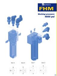
833-4E2-264 (Grommet type)833-4E2-266 (Grommet type)-37 (Conduit type)830-4E2 830-37-24-2.1(Through hole for pulling out lead wire)(113.6)4738(For wiring outlet: G1/2)Manual overrideRc1/8Applicable cable outer diameter610 (812)For wiring outlet: G1/2(Widthacross flats)221038655544.18.5PR197.53236.5286248Viewed from A2-7(Mounting hole)34-39 (DIN connector)830-39-23840.52-Rc3/4 (-266)2-Rc1/2 (-264)22394A 2B197.51845.54A 2BAB6273AA1PB5R13R210513116.532.53-Rc3/4 (-266)3-Rc1/2 (-264)Dimensions of Additional Parts (To be ordered separately) (mm)Speed controller: SCE-04Speed controller: SCE-065R13R21P222737.5 37.559.5208.929.3For wiring outlet: Pg11Applicable cableouter diameter10610 27.514 11.319 (Width across flats)28830-ADSOLENOID VALVES <strong>430</strong>, 630, 830 SERIES(34)(36)(24.2)(31.2)R1/221Width across flatsR3/427Width across flatsMuffler: KM-41Muffler: KM-6(64.5)(55.5)2824(37)R1/224Width across flats32Width across flatsR3/4758
Made to OrderBottom piping sub-base (Internal pilot solenoid valve)The standard sub-base employs side piping, but the use of this subbaseenables the bottom piping. Use it when there is not enoughpiping space in the sub-base side-surface application. Two types ofport sizes are provided for the bottom piping sub-base in each series(the PR port size, however, is Rc1/8).Bottom piping manifoldB(Internal pilot solenoid valve)The standard manifold employs side piping, but theuse of this manifold enables the bottom piping. Useit when there is not enough piping space in themanifold side-surface application.<strong>430</strong> seriesBottom piping sub-base-282-283630 seriesBottom piping sub-base-283-284Manifold model Port Piping size1P Rc 1/2<strong>430</strong>MB4A,2B Rc 1/43R2,5R1 Rc 1/2PR Rc 1/8Manifold model Port Piping size1P Rc 1/2630MB4A,2B Rc 3/83R2,5R1 Rc 1/2PR Rc 1/8Rc 1/4 specificationRc 3/8 specificationRc 3/8 specificationRc 1/2 specification830 seriesBottom piping sub-baseBottom dimensions(mm)<strong>430</strong> seriesOrder code: <strong>430</strong>MB-284Rc 1/2 specification-286Rc 3/4 specification2-Rc1/4(per each station)Bottom dimensions(mm)<strong>430</strong> series630 series4A4A 4A 4A382B 2B 2B 2B30Note13 3 3 354 3333 53Note2PR -283-282 -284-283Notes: 1. With serial transmission module :-BSR, the length is 119.2. With serial transmission module :-BSL, the length is 118.630 seriesOrder code: 630MB2-Rc3/8(per each station)830 series4A 4A 4A 4A4A402BPR5R11P3R2 -286-284Remarks: The sub-base mass is the same as the standard one.For the <strong>430</strong> series, see “<strong>Solenoid</strong> <strong>Valve</strong> Mass” on p.730, for the630 series, see p.742, and for the 830 series, see p.754.7592B 2B 2B 2B5 5 5 564 4343 63Manifold MassManifold model<strong>430</strong>MB630MBMass calculation of each unit(n=number of units)35Block-off plate( )Model for <strong>430</strong> : <strong>430</strong>-BPModel for 630 : 630-BP(<strong>430</strong>n)830 [(15.17n)29.28] 100 [3.53](590n)1040 [(20.81n)36.68] 130 [4.59]g [oz.]
External pilot solenoid valveThe standard solenoid valve and sub-base is an internal pilot type. Use of this solenoid valve enables stable switching from lowpressure to high pressure range (00.9MPa {09.2kgf/cm 2 } [0131psi.]).Cautions: For the external pilot solenoid valve, use the dedicated sub-base.Use the external pilot pressures of 0.2MPa {2kgf/cm 2 } [29psi.] or more.Symbols 432-4E1 432-4E2 632-4E1 632-4E2432 sub-base dimensions(mm)5R14A2B1P3R2 PRXP2 -283-2824A 2BPR632 sub-base dimensions(mm)5R14A2B1P3R2XP2 -283-2824A 2BPRSOLENOID VALVES <strong>430</strong>, 630, 830 SERIESPRFor bottom pipingFor bottom pipingPRXP2PRFor side pipingXP2For side pipingCaution: X(P2) is a piping port for the external pilot.The mounting dimensions for ports other than the PR and X(P2) ports are the same as the <strong>430</strong> and 630 series.Dimensions of manifold side432MA432MAT432MB432MBT632MA632MB632MAT632MBT PR PRXP2XP2 PR XP2 PR XP2760
Handling Instructions and Precautions<strong>Solenoid</strong>Internal circuitVoltage specificationInternal circuitSOL.AASingle solenoidewqCOMq Bridge diode(input nonpolarized element)DC24Vw LED indicatorDouble solenoidSOL.A A COM B SOL.Be Surge voltage absorptionelementSOL.AASingle solenoidqAC100VAC200VSOL.AAwCOMBCOMSOL.Bq Varistor(surge voltage absorptionelement)w LED indicatorDouble solenoidCautions: 1. Do not apply megger between the lead wires.2. Leakage current inside the circuit could result in failure of thesolenoid valve to return, or in other erratic operation. Always useat or below the allowable leakage current listed in the solenoidspecifications on p.729 (or p.741, 753).When circuit conditions, etc. cause the current leakage toexceed the allowable leakage current, consult us.3. Since the DC24V specification does not have polarity, it can beused with either positive or negative common.4. For a double solenoid, avoid energizing both solenoidssimultaneously. <strong>Valve</strong> switching will not operate normally.761
Wiring instructionsWhen using a sub-baseGrommet typeThe terminal block is attached to the subbase,as shown in the illustration below.Remove the wiring cover, and follow theinternal circuitry to connect lead wires toeach terminal on the terminal block.Caution: For the 4E2 type or GND, pass leadwires through wiring outlet B and thelower hole GND, and then connect themto the terminal block.Conduit typeThe applicable cable outer diameter is6 [0.24in.]12 [0.47in.]. When using 10 [0.39in.] 12 [0.47in.] cable,disengage the gland screw and pull out thegrommet. The interior ring of the grommet isslitted for easy removal. Remove the interiorring only and leave the exterior ring in placefor use.ABGNDCExterior ringDIN connectorThe applicable cable outer diameter is 6[0.24in.]10 [0.39in.]. For wiring, removethe cover mounting screws and lift off theterminal cover from the base body. Insert ascrewdriver (blade width of 44.5mm [0.160.18in.]), into the groove on the boundarybetween the terminal body and the terminalcover, and remove the terminal body fromthe terminal cover. Slip a cable gland,washer, and cable gasket over a cabtyrecable (outer diameter 6 [0.24in.]10[0.39in.]), insert the cable into the wiringoutlet of the terminal cover, and connect thewires to each of the terminals on the terminalblock.When using individual wiringmanifolds (<strong>430</strong>, 630 series only)Grommet type“Wiring instructions” are the same as for thegrommet type when using a sub-base.Conduit type“Wiring instructions” are the same as for theconduit type when using a sub-base.DIN connector“Wiring instructions” are the same as for theDIN connector when using a sub-base.SOLENOID VALVES <strong>430</strong>, 630, 830 SERIESInterior ringCabtyre cable(outer diameter610mm)Applicable crimping terminalJIS C 2805 R type 1.25-3 or equivalentCaution: The connection to the terminal isidentical to the grommet type.Cable glandWasherCable gasketTerminal coverScrewdriverTerminal w (B)Terminal e (COM)Terminal bodyTerminal q (A)Terminal (GND.)Lead wire(equivalent toAWG 1820)The terminal locations and terminal numbersare as shown below: Recommended tighteningtorque for each screwN·cm {kgf·cm} [in·lbf]RecommendedScrew partstightening torqueTerminal screw 58.8 {6.0} [5.2]Sub-base wiring cover mounting screw 58.8 {6.0} [5.2]Collective wiring manifold68.6 {7.0} [6.1]wiring cover mounting screwIndividual wiring manifoldwiring cover mounting screw58.8 {6.0} [5.2]132LiftSOL.ASOL.BABCOMTerminal number123BaseGND762
Handling Instructions and Precautions When using collective wiringmanifolds (<strong>430</strong>, 630 series only)Terminal blockThe terminal block is available on themanifold as shown in the illustration below.Remove the wiring cover, and following theinternal circuit described above, connectlead wires to each terminal on the terminalblock. The wiring cover can be removed byonly loosening the wiring cover mountingscrews.Multi connectorAs shown in the illustration below, align thepin numbers on the multi connector andthose on the multi connector assembly toconnect them.D-sub connectorAlign the pin numbers on the D-subconnector and those on the D-subconnector assembly to connect them.Multi connector assembly(to be ordered separately)The pin locations and pin numbers are asshown below:D-sub connector assembly(to be ordered separately)The pin locations and pin numbers are asshown below:1 13Serial transmission system(For <strong>430</strong> series only)For the usage and system configurationmethods, see the relevant User’s Manual.Optional code Applicable PC manufacturer User’s manual No. NoteOR OMRON Document: HV007MB Mitsubishi Electric Document: HV006Fuji ElectricFJ FA Components & Document: HV012SystemsSP SHARP Document: V107MSMatsushita ElectricWorksDocument: V109HT Hitachi Document: V108Note : When you require a User’s Manual,consult us.Remark : The address number is placed on thesolenoid at shipping.Conduit capA conduit cap is attached to a manifold’s endblock. Attach it to a wiring outlet that is not inuse on one side.stn.1stn.2stn.3stn.81016521SOL.ASOL.BSOL.ASOL.BSOL.ASOL.BSOL.ASOL.B1 49152024Pin numberA 1B 2COM 23A 3B 4COMA 5B 6COMPin numberA 15B 16COM 24Caution: Since the DC24V specification does nothave polarity, it can be used with eitherpositive or negative common.Additional parts (to be ordered separately)Multi connector assembly order code<strong>430</strong>M-AM240-A-Cable length150 : 1500mm [59in.]300 : 3000mm [118in.]500 : 5000mm [197in.]Component partsPlug: 206837-1 (1 pc.)Cable clamp: 206138-1 (1 pc.)Socket: 66101-2 (18 pcs.)Manufactured by Tyco Electronics AMP K.K.stn.1stn.2stn.3stn.814 25SOL.ASOL.BSOL.ASOL.BSOL.ASOL.BSOL.ASOL.BPin numberPin numberA 1B 2COM 23A 3B 4COMA 5B 6COMA 15B 16COM 24Cautions: 1. Since the DC24V specificationdoes not have polarity, it can beused with either positive ornegative common.2. Use M3 for the connector mountingscrew.Additional parts (to be ordered separately)D-sub connector assembly order code<strong>430</strong>M-AD250-A-Cable length150 : 1500mm [59in.]300 : 3000mm [118in.]500 : 5000mm [197in.]Component partsPlug: D type connector in accordance with MILNumber of pins: 25Connector mounting screw (molded type): M30.5763
Plug-inAttaching and removing valvesThis series is a plug-in type valve thatenables valve replacement without removingthe air piping and electrical wiring.To remove the valve body from the sub-baseor manifold, loosen the valve mountingscrews (4 places), and pull the valve bodystraight out. To mount the valve body, alignthe valve body plugs to the socket on theupper surface of the sub-base or manifold, fitit straight in, and then tighten the valvemounting screws. The recommendedtightening torques for the valve mountingscrews are as shown below.Manual overrideManual overrideUsing a fingertip, press the manual overrideall the way down to operate.The manual override’s protruding dimensionis 0.7mm [0.028in.].For the single solenoid, the valve worksthe same as when in the energized stateas long as the manual override is pusheddown, and returns to the normal positionupon release.Caution: Do not attempt to remove the pilot valve.N·cm {kgf·cm} [in·lbf]<strong>Series</strong> name Recommended tightening torque<strong>430</strong> series 105.9 {10.8} [9.37]630 series 137.3 {14.0} [12.15]830 series 137.3 {14.0} [12.15]For the double solenoid, pressing themanual override on the 14(SA) sideswitches the 14(SA) to enter the energizedposition, and the unit remains in that stateeven after the manual override is released.To return it to the normal position, operatethe manual override on the 12(SB). This isthe same for the solenoid 12(SB).Locking type manual lever override(<strong>430</strong>,630 series only)Shown in the illustration below, the lockingtype manual lever override is normally(when lock is released) set to 0 on the slitin the lever. To lock it, turn the lever slit 90degrees in the direction of 1.UnlockedLockedSOLENOID VALVES <strong>430</strong>, 630, 830 SERIESDimensionsCautions: 1. The <strong>430</strong>, 630 series valves are pilottype solenoid valves. As a result,the manual override cannot switchthe main valve without air suppliedfrom the 1(P) port.2. Always release the lock of thelocking type manual lever overridebefore commencing normaloperation.764
Handling Instructions and PrecautionsManifold (<strong>430</strong>, 630 series only)PipingBlock-off platePort isolatorSince the 1(P), 3(R2), 5(R1) ports are onboth ends of the manifold, the pipingdirection can be selected depending on theapplication.At shipping, plugs are temporarily pluggedon ports at one end, but are not firmlytightened. Regardless of which end thepiping is connected to, always remove theplug, apply sealing tape or another sealingagent, and securely tighten the plug into theunused ports.Parts orderingNo.Partsq Manifold additional unit Note 1To close the unused stations, use the blockoffplate available as additional parts (Ordercode for <strong>430</strong>: <strong>430</strong>M-BP, Order code for 630:630M-BP).Cautions: 1. For the 1(P) port piping, use a size thatmatches the manifold’s pipingconnection port.2. When installing piping or mufflers to the3(R2), 5(R1) ports, ensure there will beminimum exhaust resistance.3. On rare occasions, exhaust caninterfere with other valves andactuators. In this case, let exhaust from3(R2), 5(R1) ports on both ends.4. When a multiple number of valves areoperating simultaneously on a multi-unitmanifold, or during high frequencyapplications, supply air from the 1(P)ports on both ends, and exhaust air fromthe 3(R2), 5(R1) ports on both ends.When additional parts are required due to manifold increases or replacements, examine thedisassembly diagram below to place orders, using the following order codes:Collective wiring manifold (Wiring type is terminal block only)For <strong>430</strong> series<strong>430</strong>M Note 2 A(B) Note 3 SOrder CodesFor 630 series630M Note 2 A(B) Note 3 Sw Manifold block assembly <strong>430</strong>MA(B) Note 3 -MB 630MA(B) Note 3 -MBe Auxiliary parts set <strong>430</strong>MA-MHB 630M-MHBr End block set <strong>430</strong>MA-EB 630MA-EBt Wiring cover <strong>430</strong>MA-MC Note 4 630MA-MC Note 4Remark: The recommended tightening torque for manifold connecting bolts is 196.1Ncm {20kgfcm} [17.4inlbf].Notes: 1. When ordering an additional manifold unit, first list the order code, and then enter the solenoid valve modelrequired for the number of units. For the method of order entry, see the manifold order codes.(Example) <strong>430</strong>M2AS stn. 1 <strong>430</strong>-4E1 DC24Vstn. 2 433-4E2 DC24V 1 setWhen ordering additional manifold units, it is necessary to order a new wiring cover (correspondsto the total number of units).2. Enter the number of units 1n into . However, the total number of units on the manifold afteradding new units should be 10 units or less.3. When ordering bottom piping (made to order), enter B instead of A.4. Enter the number of units 210 into .When entering a port isolator order code(-MSP, -MSR, -MSD) to the manifold ordercode, the port isolators are installed atshipping in the space between thedesignated station and the station to its right(with the larger stn. number). Inserting portisolators in the 1(P) and 3(R2), 5(R1) portsbetween the designated station and thestation to its right can isolate the air path bythe port isolator position into stations withsmaller station numbers and stations withlarger station numbers. Port isolatorfor 1(P) port(-MSP) Port isolator for3(R2), 5(R1) ports(-MSR) Port isolator for1(P), 3(R2), 5(R1)ports(-MSD)Example: When a port isolator order code hasbeen placed for stn.2RAPA(0.3MPa)RAPort isolator for1(P) portCan supply 2 differentpressure.Can prevent exhaust airinterference.Can supply 2 differentpressure, and preventexhaust air interference.stn.1 stn.2 stn.3 stn.4RBPB(0.5MPa)RBPort isolator for3(R2), 5(R1) portsPA air is supplied to stn.1 and stn.2, while PB airis supplied to stn.3 and stn.4. Moreover, RA onstn.1 and stn.2 is exhausted from the left side,and RB on stn.3 and stn.4 is exhausted from theright side.Collective wiring manifold disassembly diagram<strong>Valve</strong> mounting screwerSingle valve unitGasketJointqeEnd blockGasketwWiring cover mounting screwrPort isolatortWiring coverq765
Individual wiring manifoldNo.yPartsManifold additional unit Note 1Order CodesFor <strong>430</strong> seriesFor 630 series<strong>430</strong>M Note 2 A (B) TS- Note 3 630M Note 2 A(B) TS- Note 3u Auxiliary parts set <strong>430</strong>MA-MHB 630M-MHBi End block set <strong>430</strong>MAT-EB 630MAT-EBRemark:The recommended tightening torque for manifold connecting bolts is 196.1N·cm {20kgf·cm}[17.4in·lbf].Notes: 1. When ordering a manifold additional unit, first list the order code, and then enter the solenoid valve modelrequired for the number of units. For the method of order entry, see the manifold order codes.(Example) <strong>430</strong>M2ATS-37 stn. 1 <strong>430</strong>-4E1 DC24Vstn. 2 433-4E2 DC24V 1 set2. Enter the number of units 1n into . However, the total number of units on the manifold afteradding new units should be 10 units or less.3. Enter wiring type: Blank (Grommet type), -37 (Conduit type), -39 (DIN connector) into .Individual wiring manifold disassembly diagramuiyiuSOLENOID VALVES <strong>430</strong>, 630, 830 SERIES766
767