(JHD Series) & Stainless Steel (LSSL Series) - Lehigh Fluid Power
(JHD Series) & Stainless Steel (LSSL Series) - Lehigh Fluid Power
(JHD Series) & Stainless Steel (LSSL Series) - Lehigh Fluid Power

Create successful ePaper yourself
Turn your PDF publications into a flip-book with our unique Google optimized e-Paper software.
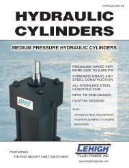
CATALOG 8201JLPNEUMATICCYLINDERSSTANDARD BRASS ANDSTEEL CONSTRUCTIONALL-STAINLESS STEELCONSTRUCTIONNFPA TIE-ROD DESIGNCUSTOM DESIGNSALSO:VALVE ACTUATORSSPRING EXTEND AND RETRACTPOSITION SENSING CYLINDERSBOOSTERSLINEAR AIR MOTORSFEATURING THE EXCLUSIVEMIRACALUBE ®SELF-LUBRICATING SYSTEMwww.lehighfluidpower.com
FLUID POWER . . .Pneumatic and Hydraulic <strong>Power</strong>!You are sure to note some special features on our industrial pneumatic and hydraulic cylinders.Like our exclusive Miracalube ® lubricant on our air cylinders. And our unique ability to mounttie-rod limit switches on hydraulic cylinders. And then there's our line of stainless steel cylinders.Industrial Pneumatic andHydraulic CylindersWe have been manufacturing cylinderssince the 1940's. Our standard materialsinclude brass tubing for our air and mediumduty hydraulics, steel for high pressure, andstainless steel for any application. With ourcapabilities your engineering applicationgets focused and expert attention, and yourpurchasing gets competitive pricing.We welcome the one-of-a-kind special aswell as the OEM quantity. So whether yourrequirements are frequent or few, standardor custom, we are here to help.Better By DesignAmong our innovations: The Miracalube ®self-lubricated air cylinder. Its lubricant ismade of FDA approved materials and doesnot mist into the atmosphere. Over 50million linear feet of piston travel have beenreported in case histories!Among our features: Limit switches canbe tie-rod mounted on our medium dutyhydraulic cylinders! This is unique in theindustry, allowing sensing to be setanywhere along the stroke withoutexternal mechanisms.And… These cylinders are offered from thecatalog in bore sizes from 3/4" to 20" inpressures up to 250 PSI in air and up to3,000 PSI hydraulic, with custom designfor specials!The information in this catalog should be used as a guide for your consideration, investigation and verification.This information does not constitute a warranty or representation and we assume no legal responsibility orobligation with respect thereto, and the use to which such information may be put.As product improvement is a continuous process, specifications are subject to change without notice.2
SERIES <strong>JHD</strong>HEAVY DUTY AIR CYLINDERThe <strong>Lehigh</strong> Miracalube ® Air CylinderThe Only Real Self-Lube Air Cylinder in the WorldBENEFITS!The true test of a cylinder is how well it performs in your application. This has been ourphilosophy since 1948 when we first designed and manufactured the exclusive Miracalube ®self-lubricated air cylinder system. This combination of innovative design features plus the finestavailable materials and workmanship has earned us an industry-wide reputation of excellence.The unique Miracalube ® internal reservoirsystem meters a specially formulated non-toxic,ingestible, low-vapor pressure lubricant - totallysolvent-free for millions of trouble free cycles.Unlike contaminating airline lubricants,Miracalube ® will not mist or atomize and, beingsolvent-free, will not dissolve seals or fuselipseals to the tube ID if the piston remains inone position for any extended time. This meansthat you can run our cylinder without the usualinline lubricator, and that means no spray fromthe exhaust!Other standard <strong>Lehigh</strong> high-performancefeatures include a tough, no-rust/non-pittinghard-tempered brass cylinder tube forextended piston seal life and a long self-lubed,readily removable sintered bronze rod bearingwith grooved design for doubled oil capacity.Our <strong>Series</strong> <strong>JHD</strong> air cylinders offers bore sizesfrom 3/4" to 20", maximum pressures up to250 PSI, and strokes to over 10 feet. Wedesign to match our customers' cylinder andseal requirements, whatever they may be.You'll benefit with the Miracalube ® air cylinder's longer life, less downtime, no air line lubrication,and smooth, low breakaway startups for increased productivity. Let <strong>Lehigh</strong>'s sales andengineering departments help you select the best product for your application needs.4
The <strong>Series</strong> <strong>JHD</strong> Heavy Duty Air CylinderThe Miracalube ® <strong>Series</strong> . . . Real Self-LubricationFEATURES!The <strong>Series</strong> <strong>JHD</strong> Heavy Duty Air Cylinder Comes Standard with the Following Design Features:<strong>Steel</strong> Bearing HousingC1018/C1117CDFront Removable withoutCylinder DisassemblyWipers, O-RingsPolyurethane Rod Wipers and Tube O-RingsBronze BearingSintered Bronze/SAE 660Tie Rods - High StrengthC1045/C1050CD-SR/15V32/A311-A311M<strong>Steel</strong> 100,000 Min. Yield1/4" to 3/4" dia. with Rolled ThreadsSeals - Lower Friction,Faster BreakawayInternally Lubricated CarboxylatedNitrile (ILCN), Piston and RodBearing FlangeC1018/C1117CD/A36 <strong>Steel</strong>Dynamic Lip Cushion SealsOpen HeadC1018/C1117CD/A36 <strong>Steel</strong>Miracalube ® Self-LubricationPermanent, Metered LubricantNo Air Line Lubrication RequirementCylinder Tubing - Brass to 8" Dia. Bore1" to 8" Bore - Seamless Drawn Alloy67/33/Alloy 443 Hard Tempered Brass10" to 20" Bore - ST 52.3DOM/C1026CD/A513 <strong>Steel</strong>Chrome I.D. .0003/.0007Piston - with Lubricant Reservoir1" to 8" Bore - C1018/C1117CD <strong>Steel</strong>10" to 20" Bore - C1018/C1117CD/A36 or80-55-06 Ductile Iron with Wear BandPiston Rod5/8" thru 3 1/2" - C1045/C1050/C1141CD100,000 PSI Min. YieldChrome Plated .0003/.0007End CapC1018/C1117CD/A36 <strong>Steel</strong>PortsNPT StandardOther … Pneumatic Service to 250 PSI … Operating Temp. from 0° to 165° F (Standard), to 400°F (Optional Seals)Custom Pneumatic CylindersAn important part of our business is the custom cylinder design. The <strong>Series</strong> <strong>JHD</strong> pneumatic cylinder isavailable in virtually any configuration required by your special application. When you contact us with yourdesign challenges, chances are that our engineering will meet the requirements of your special mounting,material, seal, temperature, sensing or other needs.5
TIE ROD MOUNTED CYLINDERS3/4" AND 1" BORE SBA SERIES AIR CYLINDERS3/4" AND 1" BORE MSBA SERIES LINEAR AIR MOTORS*For spring return cylinder, add twice stroke to "+ stroke" dimensionMiracalube ® Small Bore Air Cylinders and Small Bore Linear Air Motors®®**For spring return cylinder, add 3/4" to "+ stroke" dimensionENVELOPE AND MOUNTING DIMENSIONS NOT AFFECTED BY ROD DIAMETER10Note: All SBA and MSBA series cylinders are furnished with style 10 threaded nose mount and nut in additionto other available mountsFor pneumatic service to 150 PSI
TIE ROD MOUNTED CYLINDERS (Cont.)ROD END DIMENSIONSRod Dia. MM A BA BD BF C CC E LA V W1/4 5/8 7/16 3/4–16 1 1/4 1/4–28 1 1/8 1 27/32 13/16 1 7/325/16 5/8 7/16 3/4–16 1 1/4 5/16–24 1 3/8 1 27/32 13/16 1 7/32Description: Small Bore Air Cylinders and Linear Air Motors are designed to be used as components ofmachines or other applications where reliability in rugged service is the prime consideration.These units are built to operate without maintenance for millions of high-speed cycles because of thecombined features which are standard only in <strong>Lehigh</strong> Heavy Duty Cylinders.Standard Construction Features: SBA and MSBA <strong>Series</strong>• Fast break-away, lip type cushion seals (on all doubleacting cylinders)• Strong, special alloy, low inertia piston rod for highspeed service• Long Oilite piston rod bearing for impact resistance• <strong>Steel</strong> heads and pistons for impact resistance• 1/8" NPT ports, unrestricted for full flow• Low friction U-cup piston and piston rod seals for longlife and speed of response• Smooth tempered brass tubing for corrosion resistance• High tensile tie rodsAdditional Feature for MSBA <strong>Series</strong>• Valve-in-head construction simplifies installation by direct connection of electric and air lines to cylinderMSBA Electrical Specifications• Miniature 3-way solenoid operated valve• 6 watts power consumption• 110 volt 60 Hz standard• Spade terminal coil with ground per DIN 43650• Continuous duty rated, Class A, molded coil• Voltages include: 24, 120, 240, 480 VACOther voltages availableOrdering Information• Cylinders are furnished with cushions both ends, exceptspring return• Standard port position is #1Select Product Designation and also specify:• Standard design or with MIRACALUBE ®• Stroke length• Mounting style (Note: #10 nose mount with nut is providedas standard, and in addition to optional second mount)11
TIE ROD, FLUSH, NOSE AND FOOT MOUNTED CYLINDERS1" BORE SERIES <strong>JHD</strong> AND <strong>LSSL</strong> AIR CYLINDERSSTANDARD IN BRASS TUBE DESIGN AND ALL STAINLESS STEEL DESIGN!TIE ROD MOUNTING DESCRIPTIONDIMENSIONS AFFECTED BY ROD DIAMETER12
FLANGE, CLEVIS PIVOT AND TRUNNION MOUNTED CYLINDERS1" BORE SERIES <strong>JHD</strong> AND <strong>LSSL</strong> AIR CYLINDERS (Cont.)ENVELOPE AND MOUNTING DIMENSIONS NOT AFFECTED BY ROD DIAMETER13
TIE ROD AND NOSE MOUNTED CYLINDERS1 1/2" TO 6" BORE SERIES <strong>JHD</strong> AND <strong>LSSL</strong> AIR CYLINDERSSTANDARD IN BRASS TUBE DESIGN AND ALL STAINLESS STEEL DESIGN!TIE ROD MOUNTING DESCRIPTIONENVELOPE AND MOUNTING DIMENSIONS NOT AFFECTED BY ROD DIAMETER14
TIE ROD AND NOSE MOUNTED CYLINDERS (Cont.)DIMENSIONS AFFECTED BY ROD DIAMETERBORE1 1/222 1/23 1/4456RODDIA.MMKKSTDTHREAD SIZE ROD AND PILOT DIMENSIONS ENVELOPE DIMENSIONSCC FF AB+.000-.002C D LA NA V W YZBADDSTROKEZMADD 2XSTROKE5/8 7/16-20 1/2-20 5/8-18 3/4 1.124 3/8 1/2 1 3/8 9/16 1/4 5/8 1 15/16 4 7/8 6 1/81 * 3/4-16 7/8-14 1-14 1 1/8 1.499 1/2 7/8 2 1/8 15/16 1/2 1 2 5/16 5 1/4 6 7/85/8 7/16-20 1/2-20 5/8-18 3/4 1.124 3/8 1/2 1 3/8 9/16 1/4 5/8 1 15/16 4 15/16 6 1/81 3/4-16 7/8-14 1-14 1 1/8 1.499 1/2 7/8 2 1/8 15/16 1/2 1 2 5/16 5 5/16 6 7/81 3/8 * 1-14 1 1/4-12 1 3/8-12 1 5/8 1.999 5/8 1 1/8 2 7/8 1 5/16 5/8 1 1/4 2 9/16 5 9/16 7 3/85/8 7/16-20 1/2-20 5/8-18 3/4 1.124 3/8 1/2 1 3/8 9/16 1/4 5/8 1 15/16 5 1/16 6 1/41 3/4-16 7/8-14 1-14 1 1/8 1.499 1/2 7/8 2 1/8 15/16 1/2 1 2 5/16 5 7/16 71 3/8 1-14 1 1/4-12 1 3/8-12 1 5/8 1.999 5/8 1 1/8 2 7/8 1 5/16 5/8 1 1/4 2 9/16 5 11/16 7 1/21 3/4 * 1 1/4-12 1 1/2-12 1 3/4-12 2 2.374 3/4 1 1/2 3 1/2 1 11/16 3/4 1 1/2 2 13/16 5 15/16 81 3/4-16 7/8-14 1-14 1 1/8 1.499 1/2 7/8 1 7/8 15/16 1/4 3/4 2 7/16 6 7 1/21 3/8 1-14 1 1/4-12 1 3/8-12 1 5/8 1.999 5/8 1 1/8 2 5/8 1 5/16 3/8 1 2 11/16 6 1/4 81 3/4 1 1/4-12 1 1/2-12 1 3/4-12 2 2.374 3/4 1 1/2 3 1/4 1 11/16 1/2 1 1/4 2 15/16 6 1/2 8 1/22 * 1 1/2-12 1 3/4-12 2-12 2 1/4 2.624 7/8 1 11/16 3 5/8 1 15/16 1/2 1 3/8 3 1/16 6 5/8 8 3/41 3/4-16 7/8-14 1-14 1 1/8 1.499 1/2 7/8 1 7/8 15/16 1/4 3/4 2 7/16 6 7 1/21 3/8 1-14 1 1/4-12 1 3/8-12 1 5/8 1.999 5/8 1 1/8 2 5/8 1 5/16 3/8 1 2 11/16 6 1/4 81 3/4 1 1/4-12 1 1/2-12 1 3/4-12 2 2.374 3/4 1 1/2 3 1/4 1 11/16 1/2 1 1/4 2 15/16 6 1/2 8 1/22 1 1/2-12 1 3/4-12 2-12 2 1/4 2.624 7/8 1 11/16 3 5/8 1 15/16 1/2 1 3/8 3 1/16 6 5/8 8 3/41 3/4-16 7/8-14 1-14 1 1/8 1.499 1/2 7/8 1 7/8 15/16 1/4 3/4 2 7/16 6 5/16 7 3/41 3/8 1-14 1 1/4-12 1 3/8-12 1 5/8 1.999 5/8 1 1/8 2 5/8 1 5/16 3/8 1 2 11/16 6 9/16 8 1/41 3/4 1 1/4-12 1 1/2-12 1 3/4-12 2 2.374 3/4 1 1/2 3 1/4 1 11/16 1/2 1 1/4 2 15/16 6 13/16 8 3/42 1 1/2-12 1 3/4-12 2-12 2 1/4 2.624 7/8 1 11/16 3 5/8 1 15/16 1/2 1 3/8 3 1/16 6 15/16 91 3/8 1-14 1 1/4-12 1 3/8-12 1 5/8 1.999 5/8 1 1/8 2 1/2 1 5/16 1/4 7/8 2 13/16 7 1/16 8 3/41 3/4 1 1/4-12 1 1/2-12 1 3/4-12 2 2.374 3/4 1 1/2 3 1/8 1 11/16 3/8 1 1/8 3 1/16 7 5/16 9 1/42 1 1/2-12 1 3/4-12 2-12 2 1/4 2.624 7/8 1 11/16 3 1/2 1 15/16 3/8 1 1/4 3 3/16 7 7/16 9 1/22 1/2 1 7/8-12 2 1/4-12 2 1/2-12 3 3.124 1 2 1/16 4 1/2 2 3/8 1/2 1 1/2 3 7/16 7 11/16 10FIRST ROD SIZE SHOWN FOR EACH BORE SIZE IS STANDARD ROD* ROD END CUSHIONS AVAILABLE ONLY AS NON-ADJUSTABLE TYPE - CONSULT LEHIGH15
FOOT AND FLUSH MOUNTED CYLINDERS1 1/2" TO 6" BORE SERIES <strong>JHD</strong> AND <strong>LSSL</strong> AIR CYLINDERSSTANDARD IN BRASS TUBE DESIGN AND ALL STAINLESS STEEL DESIGN!ENVELOPE AND MOUNTING DIMENSIONS NOT AFFECTED BY ROD DIAMETER16
FOOT AND FLUSH MOUNTED CYLINDERS (Cont.)DIMENSIONS AFFECTED BY ROD DIAMETER17
CLEVIS, PIVOT AND SPHERICAL BEARING MOUNT1 1/2" TO 6" BORE SERIES <strong>JHD</strong> AND <strong>LSSL</strong> AIR CYLINDERSSTANDARD IN BRASS TUBE DESIGN AND ALL STAINLESS STEEL DESIGN!ENVELOPE AND MOUNTING DIMENSIONS NOT AFFECTED BY ROD DIAMETERNotes: Clevis Pin comes standard with 8F and 8D MountsType "B" rod end style is preferred on the 8S style mount cylinder due to the availability of mounting accessories.See pages 54-57 for mounting accessories18
CLEVIS, PIVOT AND SPHERICAL BEARING MOUNT (Cont.)DIMENSIONS AFFECTED BY ROD DIAMETERSee pp. 54-57 for Mounting Accessories19
FLANGE MOUNTED CYLINDERS1 1/2" TO 6" BORE SERIES <strong>JHD</strong> AND <strong>LSSL</strong> AIR CYLINDERSSTANDARD IN BRASS TUBE DESIGN AND ALL STAINLESS STEEL DESIGN!ENVELOPE AND MOUNTING DIMENSIONS NOT AFFECTED BY ROD DIAMETEREE *BORE E NPTF SAE F FB G J K R TF UF LB PADD STROKE1 1/2 2 3/8 6 3/8 5/16 1 1/2 1 1/4 1.43 2 3/4 3 3/8 4 2 1/42 2 1/2 3/8 6 3/8 3/8 1 1/2 1 5/16 1.84 3 3/8 4 1/8 4 2 1/42 1/2 3 3/8 6 3/8 3/8 1 1/2 1 5/16 2.19 3 7/8 4 5/8 4 1/8 2 3/83 1/4 3 3/4 1/2 10 5/8 7/16 1 3/4 1 1/4 3/8 2.76 4 11/16 5 1/2 4 7/8 2 5/84 4 1/2 1/2 10 5/8 7/16 1 3/4 1 1/4 3/8 3.32 5 7/16 6 1/4 4 7/8 2 5/85 5 1/2 1/2 10 5/8 9/16 1 3/4 1 1/4 7/16 4.10 6 5/8 7 5/8 5 1/8 2 7/86 6 1/2 3/4 12 3/4 9/16 2 1 1/2 7/16 4.88 7 5/8 8 5/8 5 3/4 3 1/8* NPTF PORTS FURNISHED UNLESS OTHERWISE SPECIFIED20
FLANGE MOUNTED CYLINDERS (Cont.)DIMENSIONS AFFECTED BY ROD DIAMETER21
TRUNNION MOUNTED CYLINDERS1 1/2" TO 6" BORE SERIES <strong>JHD</strong> AND <strong>LSSL</strong> AIR CYLINDERSSTANDARD IN BRASS TUBE DESIGN AND ALL STAINLESS STEEL DESIGN!ENVELOPE AND MOUNTING DIMENSIONS NOT AFFECTED BY ROD DIAMETER22
TRUNNION MOUNTED CYLINDERS (Cont.)DIMENSIONS AFFECTED BY ROD DIAMETER23
TIE ROD MOUNTED CYLINDERS8" TO 12" BORE SERIES <strong>JHD</strong> AND <strong>LSSL</strong> AIR CYLINDERSAVAILABLE IN STANDARD CONSTRUCTION AND ALL STAINLESS STEEL DESIGN!MOUNTING DESCRIPTIONFor ROD END Styles and dimensional drawings, see p.23ENVELOPE AND MOUNTING DIMENSIONS NOT AFFECTED BY ROD DIAMETERDIMENSIONS AFFECTED BY ROD DIAMETER24
FOOT AND FLUSH MOUNTED CYLINDERS8" TO 12" BORE SERIES <strong>JHD</strong> AND <strong>LSSL</strong> AIR CYLINDERSAVAILABLE IN STANDARD CONSTRUCTION AND ALL STAINLESS STEEL DESIGN!For ROD END Styles and dimensionaldrawings, see p.23ENVELOPE AND MOUNTING DIMENSIONS NOT AFFECTED BY ROD DIAMETERDIMENSIONS AFFECTED BY ROD DIAMETER25
CLEVIS AND SPHERICAL BEARING MOUNTED CYLINDERS8" TO 12" BORE SERIES <strong>JHD</strong> AND <strong>LSSL</strong> AIR CYLINDERSAVAILABLE IN STANDARD CONSTRUCTION AND ALL STAINLESS STEEL DESIGN!ENVELOPE AND MOUNTING DIMENSIONS NOT AFFECTED BY ROD DIAMETERDIMENSIONS AFFECTED BY ROD DIAMETERNotes: Clevis Pin comes standard with 8F and 8D MountsType "B" rod end style is preferred on the 8S style mount cylinder due to the availability of mounting accessories.See pages 54-57 for mounting accessories26
FLANGE MOUNTED CYLINDERS8" TO 12" BORE SERIES <strong>JHD</strong> AND <strong>LSSL</strong> AIR CYLINDERSAVAILABLE IN STANDARD CONSTRUCTION AND ALL STAINLESS STEEL DESIGN!ENVELOPE AND MOUNTING DIMENSIONS NOT AFFECTED BY ROD DIAMETERDIMENSIONS AFFECTED BY ROD DIAMETER27
TRUNNION MOUNTED CYLINDERS8" TO 12" BORE SERIES <strong>JHD</strong> AND <strong>LSSL</strong> AIR CYLINDERSAVAILABLE IN STANDARD CONSTRUCTION AND ALL STAINLESS STEEL DESIGN!For ROD END Styles and dimensionaldrawings, see p.30ENVELOPE AND MOUNTING DIMENSIONS NOT AFFECTED BY ROD DIAMETERDIMENSIONS AFFECTED BY ROD DIAMETER28
TIE ROD MOUNTED CYLINDERS14" TO 20" BORE SERIES <strong>JHD</strong> AND <strong>LSSL</strong> AIR CYLINDERSAVAILABLE IN STANDARD CONSTRUCTION AND ALL STAINLESS STEEL DESIGN!MOUNTING DESCRIPTIONNOTE: THE 14" BORE USES FOUR (4) TIE RODS.BORE SIZES 16"-18"-20" USE EIGHT (8) TIE RODS.For ROD END Styles and dimensional drawings, see p.30ENVELOPE AND MOUNTING DIMENSIONS NOT AFFECTED BY ROD DIAMETERNUM.BORE TIE AA AC BB DD E EE G J K R R1 R2 LF LG PRODS(NPTF)ADD STROKE14 4 15.40 - 3 3/16 7/8-14 14 3/4 1 1/4 2 3/4 2 1/4 3/4 10.90 - - 8 5/8 8 1/8 5 1/216 8 18.19 20 1/2 3 5/8 1-14 17 1/2 1 1/4 2 3/4 2 3/4 7/8 - 10.25 15.02 8 7/8 8 7/8 5 3/418 8 20.19 22 1/2 4 1/16 1-14 19 1/2 1 1/2 3 1/4 3 1/4 7/8 - 11.50 16.59 9 7/8 9 7/8 6 3/820 8 22.31 25 4 3/8 1 1/8-12 21 1/2 2 3 3/4 3 3/4 1 - 12.62 18.40 11 3/8 11 3/8 7 3/8DIMENSIONS AFFECTED BY ROD DIAMETER29
FOOT AND FLUSH MOUNTED CYLINDERS14" TO 20" BORE SERIES <strong>JHD</strong> AND <strong>LSSL</strong> AIR CYLINDERSAVAILABLE IN STANDARD CONSTRUCTION AND ALL STAINLESS STEEL DESIGN!NOTE: THE 14" BORE USES FOUR (4) TIE RODS. BORE SIZES 16"-18"-20" USE EIGHT (8) TIE RODS. (SEE ILLUSTRATIONS ON P.29)ENVELOPE AND MOUNTING DIMENSIONS NOT AFFECTED BY ROD DIAMETERDIMENSIONS AFFECTED BY ROD DIAMETER30
CLEVIS AND TRUNNION MOUNTED CYLINDERS14" TO 20" BORE SERIES <strong>JHD</strong> AND <strong>LSSL</strong> AIR CYLINDERSAVAILABLE IN STANDARD CONSTRUCTION AND ALL STAINLESS STEEL DESIGN!NOTE:THE 14" BORE USES FOUR (4)TIE RODS.BORE SIZES 16"-18"-20"USE EIGHT (8) TIE RODS.(SEE ILLUSTRATIONS ON P.29)For ROD END Styles and dimensional drawings, see p.30ENVELOPE AND MOUNTING DIMENSIONS NOT AFFECTED BY ROD DIAMETERDIMENSIONS AFFECTED BY ROD DIAMETER31
FLANGE MOUNTED CYLINDERS14" TO 20" BORE SERIES <strong>JHD</strong> AND <strong>LSSL</strong> AIR CYLINDERSAVAILABLE IN STANDARD CONSTRUCTION AND ALL STAINLESS STEEL DESIGN!For ROD END Styles and dimensionaldrawings, see p.30NOTES:1)THE 14" BORE USES FOUR (4) TIE RODS. BORE SIZES16"-18"-20" USE EIGHT (8) TIE RODS.(SEE ILLUSTRATIONS ON P.29)2) USE OF SOCKET HEAD CAP SCREWS IS PREFERREDFOR MOUNTING STYLES 6S AND 7S IN 14" TO 20"BORES DUE TO INTERFERENCE WITH THE TIE RODSAND HEX BOLT HEADS.3) ALL FLANGE MOUNTED CYLINDERS SHOULD BEMOUNTED USING HIGH STRENGTH MOUNTING BOLTS.ENVELOPE AND MOUNTING DIMENSIONS NOT AFFECTED BY ROD DIAMETERBORENUM.TIE E EE EB G J K TE LG PRODS(NPTF)ADD STROKE14 4 14 3/4 1 1/4 15/16 2 3/4 2 1/4 3/4 12 7/8 8 1/8 5 1/216 8 17 1/2 1 1/4 1 5/16 2 3/4 2 3/4 7/8 14 3/4 8 7/8 5 3/418 8 19 1/2 1 1/2 1 9/16 3 1/4 3 1/4 7/8 16 1/2 9 7/8 6 3/820 8 21 1/2 2 1 13/16 3 3/4 3 3/4 1 18 1/4 11 3/8 7 3/8DIMENSIONS AFFECTED BY ROD DIAMETER32
ORDERING INFORMATIONPART NUMBER CODE FOR AIR CYLINDERSSERIES <strong>JHD</strong> STANDARD CONSTRUCTION AIR CYLINDERSERIES <strong>LSSL</strong> ALL-STAINLESS STEEL AIR CYLINDERSERIES <strong>JHD</strong>A AIR MOTORS* SEE APPLICABLE PRODUCT SECTION FORALL OTHER PRODUCTS; e.g. SBA, MSBA,POSITION SENSING, BOOSTER, INTENSIFIER,SPRING CYLINDERCylinder Designation for Sample Code Above<strong>Series</strong> <strong>JHD</strong> Standard Construction Air Cylinder – 2" Dia. Bore5/8" Dia. Rod – 2.75" Stroke – Standard Small Male Rod End (7/16–20)Cushioned Both Ends – #2 (MX1) Mounting33
VALVE ACTUATOR CYLINDER8” to 20” BORE SERIES VAC AIR CYLINDERSTANDARD IN STEEL, AVAILABLE IN ALL-STAINLESS STEEL!8" to 14" Bores to 250 PSI16" to 20" Bores to 125 PSIVALVE ACTUATOR CYLINDER<strong>Lehigh</strong>’s uncompromising quality is built into this series of lightduty cylinder designed to meet industry’s requirements for valveand guided load actuation.As with our heavy duty air cylinder series, the VAC cylinder constructionincludes our exclusive MIRACALUBE ® self-lubricatedsystem. This unique system meters a specially formulated, nontoxic,ingestible, low vapor pressure lubricant, totally solvent-free.Unlike contaminating air line lubricants, <strong>Lehigh</strong> MIRACALUBE ®will not mist or atomize. Being solvent-free, it will not dissolveseals or fuse lipseals to the tube I.D. if the piston remains in oneposition for an extended length of time.Valve actuation applications often require more than the catalog standard design. . .■■■If a fail-safe position is needed should pneumatic pressure be lost, contact us for a spring offset option.A position indicator may be important. A rear piston rod can be added that actuates a limit switch.Perhaps you can’t use pneumatic pressure at all. Let us design the VAC for water media.Our custom designs are created for specific applications. If the standard doesn’t fit, contact us to get just theright features designed in.MOUNTINGSTYLEMOUNTING DESCRIPTIONNFPAMOUNTINGSTYLEDESCRIPTION01 MX0 NO TIE ROD EXTENSIONS02 MX1 TIE RODS EXTENDED BOTH ENDS03 MX2 TIE RODS EXTENDED CAP END04 MX3 TIE RODS EXTENDED ROD ENDDRE 01 MDX0 NO TIE ROD EXTENSIONSDRE 02 MDX1 TIE RODS EXTENDED BOTH ENDSDRE 03 MDX3 TIE RODS EXTENDED ONE END34ENVELOPE AND MOUNTING DIMENSIONS NOT AFFECTED BY ROD DIAMETEREE LG PBORE AA BB DD E NPTF F G J K R ADD STROKE8 9.10 2 5/8 5/8-18 8 1/2 1/2 5/8 1 1/4 1 1/4 9/16 6.44 4 1/8 310 11.20 3 3/4-16 10 5/8 1/2 5/8 1 1/4 1 1/4 11/16 7.92 4 5/8 3 19/3212 13.30 3 3/4-16 12 3/4 1/2 5/8 1 1/4 1 1/4 11/16 9.40 5 1/8 4 3/3214 15.40 3 3/16 7/8-14 14 3/4 3/4 3/4 1 3/4 1 3/4 3/4 10.90 6 5/8 4 7/816 18.19 3 5/8 1-14 17 1/2 1 3/4 2 2 7/8 12.86 7 3/8 5 7/1618 20.19 4 1/8 1 1/8-12 19 1/2 1 1/4 3/4 2 1/2 2 1/2 1 14.27 8 3/8 5 15/1620 22.31 4 1/2 1 1/4-12 21 1/2 1 1/2 3/4 2 3/4 2 3/4 1 1/16 15.77 9 3/8 6 3/4
VALVE ACTUATOR CYLINDER8” to 20” BORE SERIES VAC AIR CYLINDER (Cont.)DIMENSIONS AFFECTED BY ROD DIAMETERROD MAX. * THREAD SIZEB ZBBORE DIA. STROKE KK CC FF A +.000 C D LA NA TT V WF Y PLUSMM LENGTH STD -.002 STROKE8101214161820111 3/81 3/422 1/2330 INCHES24 INCHES28 INCHES65 INCHES75 INCHES85 INCHES85 INCHES3/4-163/4-161-141 1/4-121 1/2-121 7/8-122 1/4-127/8-147/8-141 1/4-121 1/2-121 3/4-122 1/4-122 3/4-121-141-141 3/8-121 3/4-122-122 1/2-123-121 5/81 5/82233 1/23 1/21.4991.4991.9992.3742.6243.1243.7491/21/25/83/47/8117/87/81 1/81 1/21 11/162 1/162 5/82 3/82 3/833 1/84 1/45515/1615/161 5/161 11/161 15/162 3/82 7/83 3/43 3/43 3/44445 1/21/41/43/83/83/81/21/21 3/81 3/81 5/81 7/822 1/42 1/41 15/161 7/82 1/82 3/433 1/23 9/165 1/266 3/48 1/29 3/810 5/811 5/81 3/81 3/81 3/422 1/233 1/270 INCHES52 INCHES64 INCHES85 INCHES85 INCHES85 INCHES85 INCHES1-141-141 1/4-121 1/2-121 7/8-122 1/4-122 1/2-121 1/4-121 1/4-121 1/2-121 3/4-122 1/4-122 3/4-123 1/4-121 3/8-121 3/8-121 3/4-122-122 1/2-123-123 1/2-121 5/81 5/82233 1/23 1/21.9991.9992.3742.6243.1243.7494.2495/85/83/47/81111 1/81 1/81 1/21 11/162 1/162 5/832 5/82 5/83 1/43 1/44 1/2551 5/161 5/161 11/161 15/162 3/82 7/83 3/83 3/43 3/43 3/4445 1/25 1/23/83/81/23/81/21/21/21 5/81 5/81 7/822 1/42 1/42 1/42 3/162 1/82 3/82 7/83 1/43 1/23 9/165 3/46 1/478 5/89 5/810 5/811 5/8FIRST ROD SIZE LISTED FOR EACH BORE SIZE IS STANDARD ROD* MAX STROKE LENGTHS SHOWN ARE FOR RIGIDLY GUIDED LOADS AT MAX 120 PSI INPUT PRESSUREORDERING INFORMATIONCylinder Designation for Sample Code Above<strong>Series</strong> VAC Valve Actuator Air Cylinder – 14” Dia. Bore – 1 3/4” Dia. Rod – 18.50” StrokeStandard Small Male Rod End (1 1/4 - 12) – Non-Cushioned – #4 (MX3) Mounting35
SPRING CYLINDERSFAIL-SAFE OPTION FOR EXTEND OR RETRACT POSITIONAVAILABLE IN ALL SERIES OF CYLINDERS, INCLUDING STAINLESS STEEL!SPRING CYLINDERSFail-safe positioning – a condition where force is provided to thecylinder to move a load to a predetermined point when pressure is removed.Spring designed cylinders may be the simplest way to accomplish this.In most cases, a mechanical spring is the only device that can be coupled to acylinder to consistently deliver a specific design force to hold a desired positionwhen input pressure is lost – and retain that force for as long as the integrity ofthe cylinder assembly is maintained.Spring extend – a spring is used so that a cylinder will stroke to the fullyextended position when input pressure is removed from the rod end port.Likewise, for spring retract, the cylinder will stroke to the fully retracted positionwhen pressure is removed from the cap end port.Applications for cylinders designed with springs are virtually unlimited, many involving the important fail-safefunction. Examples of uses include process-valve operators, conveyor-shift positioners, damper controls, collatingmachines, steam-control devices, and others where safety requires that some process absolutely must stop ifsystem power is lost.EXAMPLES OF SPRING CYLINDER DESIGN36
SPRING CYLINDERSFAIL-SAFE OPTION FOR EXTEND OR RETRACT POSITION (Cont.)DESIGNING THE SPRING CYLINDERIn a Spring Extend or a Spring Retract cylinder, a springis installed inside the cylinder tube. The spring iscompressed when the cylinder is assembled. The SpringPreload is the force this initial compression develops. TheSpring Preload is the force the cylinder will develop in thefail-safe position without system pressure.It is important to correctly identify all external forcesacting upon the cylinder. These external forces couldinclude linkage friction, seal friction external to thecylinder, or process loads that act only in theextend or retract stroke. If the external forces areunder-estimated, the system pressure may not besufficient to stroke the cylinder.It is also important to accurately determine the minimumsystem pressure available. The system pressuredetermines the bore of the spring-loaded cylinder. Ifthe system pressure is over-estimated, the cylindermay not fully stroke.Correctly applying the spring cylinder requires somethoughtful design decisions. Yet, the design process isnot complicated if complete preliminary information is provided.Such information should include:Operating Medium – PneumaticMinimum Available System Pressure – Affects thebore sizeRequired Cylinder Working Stroke – The resultant cylinderlength depends on the bore, stroke, and spring combination. As a rule-of-thumb, a spring cylinder's total strokewill be approximately twice the actual working strokerequired. Longer lengths are not uncommon.Spring Preload – The force (lbs) the cylinder develops inthe fail-safe positionOther usual design elements of the cylinder also need tobe specified; i.e., rod diameter, rod end style, mountingstyle, port type and port positions.There are two additional useful terms that neednot be supplied as application data, but arecalculated for the design:Spring Rate – The amount of force (lbs) developed bythe spring per inch of compressionSpring Final Load – The force (lbs) developed by thespring when the cylinder is fully stroked away from itsfail-safe positionORDERING INFORMATIONThe spring cylinder is a product engineered for a specificapplication. Please note, however, that this design isessentially a modification of any of our standard products.Therefore, you can consider the basic designs of our anyof our cylinder series in your application, from our 3/4"diameter bore on up to our largest bore, including the valveactuation cylinder (VAC) and the all-stainless steel cylinder(<strong>LSSL</strong>). Contact <strong>Lehigh</strong> sales and engineering for help inselecting the best product solution for your requirement.37
<strong>JHD</strong>A AIR MOTORAIR CYLINDER WITH MOUNTED VALVE<strong>JHD</strong>A 01 AIR MOTOR: 1" DIA. BOREThe <strong>JHD</strong>A 01 series air motor combines the rugged 1" dia.bore <strong>JHD</strong> 01 heavy duty air cylinder (pp.12-13) with anelectric solenoid valve to create a cylinder and valvedesigned as a unit. One electrical connection and asingle air supply line to the valve-in-head end of thecylinder simplifies installation. (For an air return model,a constant pressure air line must be connected to therod end port of the cylinder.)The standard valve used is a miniature 3-way solenoidoperated valve, 110 volt, 60 cycle, with power consumptionof 6 watts, continuous duty rated, Class A, molded coil.The electric connection is via spade terminal coil withground per DIN 43650. Other coil voltage, connectorsand enclosures are available.The <strong>JHD</strong>01 cylinder mountings available are: 01, 04, 06, 09, 10, 11, 12, 13 (see pp. 12-13).Consult factory for available options such as Miracalube ® , spring return, and low pressure air operation, or for specials<strong>JHD</strong>A AIR MOTOR: 1 1/2" to 8" DIA. BOREThe <strong>JHD</strong>A series air motor in sizes from 1 1/2" to 8" dia bore features the <strong>JHD</strong> heavy duty air cylinder and <strong>Lehigh</strong>'s4-way Slide Valve to create a linear motion, quick-response power package. This combination unit eases installationand reduces power and maintenance costs.A variety of cylinder mounting designs is available, as well as electric solenoid options. See pp.14-28 for <strong>JHD</strong> cylinderinformation and p.40 for description of the slide valve features and function.38
<strong>JHD</strong>A AIR MOTOR (Cont.)SPECIAL ELECTRICAL COILThe special electrical coil shown at the left is available at extra charge.This water-tight and explosion proof enclosure is for indoor or outdooruse in NEMA groups 4, 6, 7C, 7D, 9E, 9F 9G and 12.Piping arrangements are slightly different from the standard NEMA 1 housing.Specify "NEMA 4, 7, and 9."AUTOMATIC AIR MOTOR: 2" to 8" DIA. BOREAUTOMATIC AIR MOTORThe <strong>JHD</strong>A series automatic air motor in sizes from 2" to 8" diabore use built-in poppets to provide the signal for automaticoper-ation of the <strong>JHD</strong> heavy duty air cylinder. External limitvalves, micro-switches and push rods are eliminated.Mounted internally in the head, the poppets bleed off thesignal side of the control valve when the piston depresses thepoppet stem at the end of the stroke. Safe, reliable, andpositive, the system provides a simple and low cost methodof automatic operation.AUTOMATIC RETURNAutomatic return air motors have the built-in poppet in one head to automatically reverse the stroke from the normallyretracted or normally extended position. The start cycle may be controlled by bleed or electrical signalsAUTOMATIC RECIPROCATINGAutomatic reciprocating air motors have the built-in poppets in both heads and will maintain a reciprocating action aslong as the air supplied is provided. A start-stop selector valve may be installed in either pilot line to assure that thestroke will terminate at one extreme or the other.All the mounting styles of the <strong>JHD</strong> air cylinder are available for the automatic air motor.The 2" dia. bore automatic air motor is limited to a maximum 5/8" diameter rod size. The 2-1/2" dia. bore automatic airmotor is limited to a maximum 1" diameter rod size. There is no rod diameter limitation on larger bore sizes.ORDERING INFORMATION FOR <strong>JHD</strong>A AIR MOTORSUse the ordering part number system shown on p.33 for the standard <strong>JHD</strong> air cylinder. The air motor is designatedin the last two places with "01". Note the requirements and restrictions for the particular type of air motor describedin this section, and add the applicable description; e.g., valve model, voltage, optional electric enclosure, automaticreturn air motor, etc.39
<strong>JHD</strong>A AIR MOTOR VALVESSERIES 2MA 4-WAY SLIDE VALVEThis exclusive pneumatic slide valve was designed specifically for <strong>Lehigh</strong>'s line of Air Motors, yet it can be used inother air-powered device applications. It features Fast Acting operation . . . Up to 1,500 cycles per minute. It is Reliable. . . Operating even with improperly filtered air. It offers Long Life . . . The metal-to-metal seat is self-cleaning and operatesfor millions of cycles without significant wear. It is Compact . . . The short piston permits short valve lengthHOW IT OPERATESThe air-driven piston moves the slide. In each of its two postions,the slide opens one exhaust and one pressure port. The rate offlow of exhaust air is controlled by adjustable speed controlsmounted in each of the two exhaust orifices. Both these orificeslead to a single exhaust port. The oversized actuating pistonassures positive breakaway action, regardless of dirt in theoperating areas or of low operating pressures. The slideeffectively wipes the seat clean on each cycle, assuringa satisfactory seal even when used with improperly filtered air.CONSTRUCTIONPiston: Corrosion resistant anodized aluminum on all valves except 316 stainless steel on valve model 2MA57 AND2MA61E double bleed valves. Slide: Lapped manganese bronze. Valve Base: Lapped nickel-plated ductile iron.Valve Body: Anodized heat treated aluminum.MOMENTARY BLEED PILOTSThe balanced piston is actuated by momentary unbalancing causedby the pilot air exhausting from the opposite signal port. The exhaustingof pilot air is actuated by double solenoids integrally mounted on thevalve (Model 2MA61E) or actuated by pilot air from valves in thecustomer's control circuit (Model 2MA57).MAINTAINED PRESSURE PILOTSPositive maintained pilot pressure is used move the piston/slidemechanism, holding it in the desired actuated position.The pilot air isactuated by double solenoids integrally mounted on the valve(Model 2MA86) or actuated by pilot air from valves in the customer'scontrol circuit (Model 2MA83).AIR RETURNThe piston/slide mechanism can be supplied with one end having asmaller diameter in order to create a differential force when both sidesare subjected to the same air pressure. The larger end will overpowerthe smaller end, causing movement toward the smaller end. When air inthe larger diameter is exhausted, line pressure acting on the smallerend automatically activates the return. Control is by a single solenoidintegrally mounted on the valve (Model 2MA78) or by single pilot airactuation from a valve in the customer's control circuit (Model 2MA89).40
POSITION SENSING CYLINDERSThere are a number of different position sensing devices for fluid power cylinders. Described beloware four main types:1. Tie rod mounted limit switches that are actuated by a magnetic piston2. End-of-stroke proximity switches that are actuated by the cylinder cushion boss3. Linear displacement transducer constructed as a probe inside the cylinder rod4. Servo-type positioner for an air cylinder operating by force-balanceEach is briefly described below. Ordering instructions are provided for the tie rod mount limitswitches. Please contact <strong>Lehigh</strong> sales and engineering for application assistance to define theordering information for other positioning systems.TIE ROD MOUNTED LIMIT SWITCHESThis series of compact reed and hall effect switches is designedspecifically as a rugged yet cost effective product to electricallysense cylinder stroke position.Mounting is accomplished by clamping the switch to the cylindertie rod with the self-adjusting clamp that comes with the switch.A large number of custom circuits are featured to match yourapplication requirements.DIMENSIONAL INFORMATIONTERMINATION INFORMATION41
POSITION SENSING CYLINDERSTIE ROD MOUNTED LIMIT SWITCHES (Cont.)TECHNICAL INFORMATIONWorking Temperature: -22°F to +176°FShock Resistance: 30g @ 11 msVibration Resistance: 10 to 55 HzOperating Time: OPERATE = 1.5 usec - .6 msecLife Expectancy at Full Load: 10,000,000 CyclesRELEASE = .5 usec - .05 msecMax. Switch Current: .25 amp to 4 amp NEMA Rating: NEMA 6 with Wire Lead Cables, Style 0Repeatability: 0.001" NEMA 4 with Connectors, Styles 1,2,3,5CAUTION - LOADS: Failure to put a load in the line when testing or operating a switch can result in instantaneousfailure! The typical application load for the switches is a Programmable Logic Controller (PLC). To test the switchprior to installation the following should apply: (A) For 24 VDC use a 2,000 Ohm, 1/2 Watt resister or equivalent.(B) For 120 VAC/DC use a 12,000 Ohm, 2 Watt resister or equivalent. (C) For a 240 VAC/DC use a 20,000 Ohm,2 Watt resister or equivalent.SWITCH MODULE TYPES42
POSITION SENSING CYLINDERSTIE ROD MOUNTED LIMIT SWITCHES (Cont.)ORDERING INFORMATIONNote: When ordering a pneumatic cylinder for use with tie rod mount limit switches, in addition to the cylinder partnumber, specify “with magnetic piston for reed switch” and reference the reed switch P/N, or “with magnetic piston for halleffect switch” and reference the hall effect switch P/N. Switch not included in cylinder pricing. Order switch separately.INSTALLATION TIPS1. Always use a load when testing the switches. Failure to use a load will permanently damage the switch.2. Never test using a filament light bulb as a load. The severe inrush currents can cause switch failure or premature failure.3. There are three types of loads (See "CAUTION - LOADS" on page 42):a. Resistive loads - the inputs to a PC or PLCb. Capacitive loads - long wire runsc. Inductive loads - low power solenoids4. To control the loads, the following may be necessary:a. Resistive loads - confirm input parameters and compare to switch specificationsb. Capacitive loads - keep wire runs as short as possible and route wires away from current-carrying conductorsc. Inductive loads - use surge suppression versions of the switches or surge suppression coil connectors5. Keep the area around the switch free from dirt and magnetic particles. The particles can affect the operation of the switch.6. The switches can be used to indicate the end of piston travel or as intermediate stroke position indicators.7. Be sure the sensing area of the switch is installed completely against the cylinder tube for proper operation.43
END-OF-STROKE PROXIMITY SENSOR, THREADED MOUNTPOSITION SENSING CYLINDERSEND-OF-STROKE PROXIMITY SENSORLINEAR DISPLACEMENT TRANSDUCERSERVO-POSITIONINGThis type of switch signals the end-of stroke of the cylinder by sensing the ferrous cushion bosses on each side ofthe piston. The switch contains an internal magnet that operates a conventional single pole, double throw, form Cswitch. These O.D. threaded switches are mounted through the cylinder heads on approximately the same axialcenterline as the ports.Contact Rating: 2 Amp @ 240 VAC3 Amp @ 24 VDCResponse Time: 0.008 secondsRepeatability: 0.002" of set operating point underidentical conditionsApprovals: UL, CSA, BASEEFA and SALINEAR DISPLACEMENT TRANSDUCERLinear position sensing provides a non-contact displacement transducer that offers a high degree of accuracy.This type of unit is mounted axially through the cylinder closed head with the probe extending into a clearancein the piston rod.Linearity:Repeatability:±0.02% or better±0.001% or 0.0001" of full stroke,whichever is greaterControl Interface:Digital or Analog outputApprovals: UL and CEVarious models and protocols are available.SERVO-POSITIONING SELF-LUBRICATING AIR CYLINDERThe <strong>Lehigh</strong> Positioning Cylinder is an air cylinder directly coupled to a force-balance, servo-type positioner. Thiscombination provides a means of controlling the stroke of the piston rod to any desired length up to full stroke. Thestroke control, by a remote pressure transmitter, is repeatable and infinitely variable.This air cylinder assembly provides a precise method for creating and controlling forces by the plant operator orprocess transmitter located at some distance from the output device. It can develop long power strokes and maybe controlled to any point in its travel.Applications include:✓ Control of damper and louvre openings✓ Regulating gates, shutters and doors✓ Lifting loads to exact position✓ Positioning slides on automated equipment✓ Modulating valvesVarious models and protocols are available.44Ordering: Contact <strong>Lehigh</strong> sales and engineering for application assistance to define ordering information.Specifications are subject to change without notice
POSITION SENSING CYLINDERSSERVO-POSITIONING (Cont.)SERVO-POSITIONING SELF-LUBRICATING AIR CYLINDER (Cont.)The <strong>Lehigh</strong> Positioning Cylinder features <strong>Lehigh</strong>'sMiracalube ® self-lubrication system (see page 4). Thecylinder is rated for dry air and will give quick start-upoperation, whether frequently used or not. It operateson pneumatic service from 25 to 150 PSI and sealtemperatures to 165°F. The cylinders are from 2" to 8"diameter bore and are supplied with NFPA standardmounting styles.The Positioning Cylinder operates on the sameprinciples as the typical valve positioner widely used inthe process industries. A precisely regulated airpressure known as "instrument air" is piped to thePositioner. The pressure transmitter for this air supplyis actually a precision regulator with an adjustableoutput of 3 to 15 PSI.(This device is not part of the Positioning Cylinder.)In general, when the Positioning Cylinder receives achange in signal pressure it diverts the supply airPOSITIONER ASSEMBLY DIMENSIONSprecision regulator with an adjustable output of 3 to 15PSI. (This device is not part of the Positioning Cylinderto one side or the other of the cylinder piston, therebyresponding in stroke length proportional to the changein signal pressure.Specifically, the instrument air pressurizes a diaphragmholding the inner end of a long spring. When theinstrument air pressure changes, the diaphragm movesslightly, thus changing the air flow through a smallinternal nozzle. This change causes an internal pilotvalve to shift, thus introducing supply air to one side ofthe main cylinder piston. The differential pressuremoves the piston rod which extends the spring, pullingthe diaphragm back into its neutral position. Theunbalance of the valve is nullified, the supply air isequalized on both sides of the piston and the systemcomes to rest.APPLICATION AND NOTES1. Specify whether piston rod is to extend or retract as the transmitter pressure is increased.2. Supply with clean air free of oil and moisture not exceeding 150PSI.3. Cylinder assembly is <strong>Lehigh</strong> <strong>JHD</strong> series heavy duty air cylinder with the unique Miracalube ® self-lubricationsystem. Refer to the NFPA standard mounting styles on pages 14-28 for cylinder dimensions on bore sizesfrom 2" to 8".4. Cylinder bore sizes are from 2" to 8" diameter. Strokes are to 18" or more. Because of the forces required inbalancing the piston, bore sizes should be sized well above the theoretical rating.5. Positioner assembly is a commercial unit adapted by <strong>Lehigh</strong> to this application. The usual input range isfrom 3 to 15 PSI or 4-20 mAmp, but other instrument ranges can be designed for. Typical configurationssupplied by <strong>Lehigh</strong> in this design have included Moore, Accord and Fisher positioner controls.45
BOOSTERS, INTENSIFIERS, AIR-OIL TANKSDESIGNING WITH BOOSTERS: AIR-TO-OIL and OIL-TO-OILThe terms BOOSTER and INTENSIFIER are used interchangeably to describe these practical devices thattypically multiply standard shop air into higher hydraulic pressure (air-to-oil), although hydraulic fluid mayalso be the input medium (oil-to-oil). INTENSIFIERS tend to describe those products that provide very highpressure ratios. BOOSTERS generally provide lower pressure ratings and higher volume.There are two basic styles of BOOSTERS and INTENSIFIERS. They are the "single" and the "dual" pressurestyles. The SINGLE pressure device increases the pressure in the entire non-obstructed circuit. The DUALpressure device increases the pressure only in the portion of the circuit after the high pressure output port.BOOSTER AND INTENSIFIER SELECTIONProper selection of a booster or intensifier requires the following information:1. The input air (fluid) pressure2. The desired output pressure3. The bore and stroke of the high pressure cylinder in theapplication4. The desired output force from the high pressure cylinder5. A sketch of the fluid power circuit (see page 48 for examples)6. The type of line conductors and fitting connectors used in the circuit7. How fast the system must operate (cycles per minute)8. Booster or intensifier mounting style9. General description of the application and environment(temperature, wash down, etc.)SELECTION FORMULASUsing the above information, calculate the required values:HIGH PRESS. CYL. FORCEHIGH PRESS. CYL. AREA= OUTPUT PRESSUREOUTPUT PRESSURE X 1.05INPUT PRESSURE X .8= PRESSURE RATIOHIGH PRESSURE CYLINDER STROKE X HIGH PRESSURE CYLINDER AREA = HIGH PRESSURE CYLINDER VOLUMEHIGH PRESS. CYL. VOLUMERAM ROD AREA X .95= MINIMUM STROKE LENGTH46MINIMUM STROKE LENGTH + .25 = EFFECTIVE STROKE LENGTH (ROUND UP TO NEAREST .25 INCH)The .95 and 1.05 multipliers allow for friction and expansion in the hydraulic system. The .8 multiplier allows fornormal variations in air line pressure. These values are general guidelines and must be adjusted accordingly.
BOOSTERS, INTENSIFIERS, AIR-OIL TANKS (Cont.)SAMPLE CALCULATION: BOOSTER / INTENSIFIER SIZINGAssume a 2-1/2" dia. bore cylinder with 6" stroke. The cylinder must push 10,000 pounds for .250 inches. Thecylinder must extend and retract on pressurized air or oil at 100 PSI.What size intensifier is required?What size air-oil tank?HIGH PRESS. CYL. FORCE10,000 POUNDS= OUTPUT PRESSUREHIGH PRESS. CYL. AREA 2.5 2 X .7854= 2,037 PSIGOUTPUT PRESSURE X 1.052,037 PSIG X 1.05)= PRESSURE RATIOINPUT PRESSURE X .8 (100 PSIG X .8)= 26.74HIGH PRESSURE CYLINDER STROKE X HIGH PRESSURE CYLINDER AREA = HIGH PRESSURE CYLINDER VOLUMEThe high pressure cylinder stroke is .250 x .490 square inches = 1.23 cubic inchesHIGH PRESS. CYL. VOLUME1.23 Cubic Inch= MINIMUM STOKE LENGTH= 4.17 InchesRAM ROD AREA X .95 .31 (from Ratio Chart below) x .95MINIMUM STROKE LENGTH + .25 = EFFECTIVE STROKE LENGTH (ROUND UP TO NEAREST .25 INCH)The minimum stroke length 4.17 plus .25 = 4.42 inch effective stroke, rounding up to 4.5 inches total strokeThe following intensifiers can be used for this sample application. Choose among the three by the space availablefor the intensifier. Consult <strong>Lehigh</strong> for additional application assistance. (See page 48 for air-oil tank selection.)3-1/4" dia. bore x 5/8" ram dia. x 4-1/2" stroke4" dia. bore x 5/8" ram dia. x 4-1/2" stroke6" dia. bore x 1" ram dia. x 2" stroke47
BOOSTERS, INTENSIFIERS, AIR-OIL TANKS (Cont.)SAMPLE CALCULATION: AIR-OIL TANK SIZINGBORE 2 X .7854 X STROKE X TANK FACTOR * = MINIMUM TANK LENGTH2.5 2 X .7854 X 6 X 2.5 = 8.87 INCHESTANK VOLUME PER INCH 8.3 (from chart on p. 50)(Use the bore diameter of the working cylinder for BORE 2. Use the stroke of the working cylinder for STROKE.The TANK VOLUME PER INCH is from the chart on p.50. The volume selected for the formula yields the minimumtank length for the associated tank bore.)ROUND THE TANK LENGTH UPWARD TO THE NEAREST WHOLE INCH: 8.87 rounds to 9.0 inches long* The “Tank Factor” varies with tank length, but is generally between 2 and 3 depending on the tank application.48Note: Sample circuits are for concept illustration purposes only. Additionalsafety devices, controls and lockouts are required for safe operation.
BOOSTERS, INTENSIFIERS, AIR-OIL TANKS (Cont.)ENVELOPE AND MOUNTING DIMENSIONS49
BOOSTERS, INTENSIFIERS, AIR-OIL TANKS (Cont.)ENVELOPE AND MOUNTING DIMENSIONS50
BOOSTERS, INTENSIFIERS, AIR-OIL TANKS (Cont.)ORDERING INFORMATION51
FLANGED ROD END AND COUPLINGTYPE F FLANGED ROD ENDDIMENSIONSNote: "V" dimension varies per boresize.See data in mountingdimension tables of the respectivecylinder mounts.FLANGED ROD END COUPLINGDIMENSIONS52
SELF-ALIGNING ROD COUPLERSThis accessory is used when precise stroke alignment of the installed cylinder isquestionable. Installation is simplified, assembly costs are reduced, and cylinderlife is extended because wear is reduced on rod bearing and seals.DIMENSIONS53
CAP AND ROD END MOUNTING ACCESSORIESSTANDARD AND STAINLESS STEELROD END ACCESSORIES1. Rod Clevises and Rod Eyes are stocked to fit the standard"KK" rod thread (style A, Small Male). The "CC" thread forType D (Intermediate Male) can be supplied on special order.2. Rod Clevises are supplied with Pivot Pins as standard. PivotPins are not supplied with Rod Eyes or Eye Brackets. Theymust be ordered as separate items if desired.CAP END ACCESSORIES1. Pivot Pins are not supplied with Eye Brackets. They must beordered as separate items if desired.2. Eye Brackets are designed to mate with cylinder mountingStyle 8F (NFPA MP1) and Style 8D (NFPA MP2).3. Clevis Brackets are designed to mate with cylinder mountingStyle 8M (NFPA MP3) and Rod Eyes.NOTE: STAINLESS STEELPart Numbers in the above charts are for standard Rod Endand Cap End Accessories. All items are also available instainless steel. For stainless steel accessories, add "S" tothe end of the Part Number: e.g.; MACCL01 for standardRod Clevis, MACCL01S for stainless steel Rod Clevis.54
CAP AND ROD END MOUNTING ACCESSORIES (Cont.)STANDARD AND STAINLESS STEEL55
SPHERICAL CAP AND ROD END MOUNTING ACCESSORIESSTANDARD AND STAINLESS STEELMOUNTING DIMENSIONSMOUNTING DIMENSIONSNOTE: STAINLESS STEELPart Numbers in the charts above and on page 57 are for standard Spherical Rod End and Cap End Accessories.All items are also available in stainless steel. For stainless steel accessories, add "S" to the end of the Part Number:e.g.; LSRE-05M for standard Male Spherical Rod Eye, LSRE-05MS for stainless steel Male Spherical Rod Eye.56
SPHERICAL CAP AND ROD END MOUNTING ACCESSORIES (Cont.)STANDARD AND STAINLESS STEELMOUNTING DIMENSIONSMOUNTING DIMENSIONSNote: Spherical mounting clevises are designed to mate with spherical cylinder mounting style 8S and with spherical rod eyes.MOUNTING DIMENSIONSNote: Pivot pin is not supplied with any sphericalrod end or cap end mounting accessory. Itmust be ordered as separate item if required.57
PISTON ROD SELECTION CHARTFOR SERIES <strong>JHD</strong> AND <strong>LSSL</strong> AIR CYLINDERSSELECTION CHARTDETERMINING PROPERPISTON ROD DIAMETERTo determine proper piston roddiameter for your specific application,follow the sequence outlined below:Step 1) Determine the maximumextension thrust (push) in pounds thatyour selected bore cylinder will develop.Step 2) Using the drawings above,locate your mounting category, notingthe value of "L" in relation to extendedcylinder dimension "D".Step 3) Prior to determining the final"D" dimension in inches, check to seeif cylinder stop is necessary for propercylinder operation. As a general rule,whenever stroke length exceeds 40",use 1" of stop tube length for eachadditional 10" of stroke.Example: If stroke is 54", thestop tube length should be 2"Cylinders in categories C and D normallydo not require stop tube due tothe guided loads.58Step 4) Determine final value of "D" ininches, including stop tube addition ifapplicable. Convert "D" dimension tochart value "L" in inches, using formulashown on applicable drawing.Step 5) From the Selection Chart,locate the line showing the maximum"Thrust in Pounds" and read to the rightuntil the approximate value of "L" islocated. Read vertically upward to findthe necessary rod diameter in inches.Example: If the maximum thrust is5,000 lbs., and value of "L" has beendetermined as 110", the minimum roddiameter recommended would be 2"Step 6) Note that in some cases therecommended minimum rod diametermay exceed that which is possible forthe cylinder bore size selected. Insuch cases it may be necessary toselect a larger bore size cylinderoperating at a lower pressure whichwill still provide the required operationthrust. The larger cylinder mayaccommodate a larger rod size whichwill meet the minimum requirement.
PUSH AND PULL FORCES FOR PNEUMATIC CYLINDERSThis table lists full piston areas and push force values on the extend stroke at various input pressures.The formula used is: F = PA (Force = Pressure x Area).Also listed are displacement values in cubic feet by bore size and the corresponding value of cubicfeet of free air required to move the piston one inch.This table lists the rod areas and the corresponding force and displacement values calculated inthe same manner as those for pistons in the top table. To determine the values of the pull forceand the cubic feet of free air on the retract stroke, deduct those values in the table for the rodsize of your cylinder.Example: Assume a 4" bore cylinder with a 2" diameter rod operating at 80 PSI.Using the charts, the following theoretical values are obtained:Push (or Extend) Force = 1,006 lbs.Pull (or Retract) Force = 755 lbs (1,006 lbs from the top table, less251 lbs from the bottom table)WARRANTYSeller warrants its products free from defects in material and workmanship for a period of one year from date of shipment.This warranty excludes normal wear attributable to the particular application in which the product is used.Further, this warranty is limited exclusively to the replacement or repair of defective products, which, in the opinion of <strong>Lehigh</strong><strong>Fluid</strong> <strong>Power</strong>, Inc., have not been modified, misused, misapplied, repaired or altered by the user.<strong>Lehigh</strong> <strong>Fluid</strong> <strong>Power</strong>, Inc. accepts no responsibility or liability for damages to the purchaser arising out of a delay in or failureof delivery or resulting from any breach of any other term or obligation of <strong>Lehigh</strong> under this contract.In order to make a claim, buyer must notify <strong>Lehigh</strong> within the warranty period. Promptly after receiving such notification,<strong>Lehigh</strong> will either examine the product at the user's site or issue shipping instructions for return to it, transportation costsprepaid by buyer. All items returned must be accompanied by a copy of this acknowledgment.The above warranty comprises <strong>Lehigh</strong>'s sole and entire obligation and liability to buyer and all of those claiming underbuyer as to the products sold hereunder. All other warranties, express or implied, including but not limited to, warranties ofmerchantability and fitness, are expressly excluded.These terms and conditions of sale constitute the complete and exclusive statement of agreement superseding all oral orwritten communications and any prior agreements between the parties relating to its subject matter.THE COMPANY'S ACCEPTANCE OF THIS ORDER IS MADE EXPRESSLY CONDITIONAL UPON THE FOREGOINGTERMS AND CONDITIONS.59
FLUID POWER, INC.Manufacturer of NFPA Industrial Pneumatic and Hydraulic Tie Rod Cylinders<strong>Lehigh</strong> <strong>Fluid</strong> <strong>Power</strong>, Inc.1413 Route 179Lambertville, NJ 08530800.257.9515609.397.3487Fax: 609.397.0932www.lehighfluidpower.comsales@lehighfluidpower.com