
Create successful ePaper yourself
Turn your PDF publications into a flip-book with our unique Google optimized e-Paper software.
THERMAL PRINTER<strong>TSP800</strong> SERIESUSER’S <strong>MANUAL</strong>MODE D’EMPLOIBEDIENUNGSANLEITUNG<strong>MANUAL</strong>E DI ISTRUZIONI
Federal Communications CommissionRadio Frequency InterferenceStatementThis equipment has been tested and found to comply with the limits for a Class A digitaldevice, pursuant to Part 15 of the FCC Rules. These limits are designed to providereasonable protection against harmful interference when the equipment is operated in acommercial environment. This equipment generates, uses and can radiate radio frequencyenergy and, if not installed and used in accordance with the instruction manual, may causeharmful interference to radio communications. Operation of this equipment in a residentialarea is likely to cause harmful interference in which case the user will be required to correctthe interference at his own expense.For compliance with the Federal Noise Interference Standard, this equipment requires ashielded cable.This statement will be applied only for the printers marketed in U.S.A.Statement ofThe Canadian Department of CommunicationsRadio Interference RegulationsThis digital apparatus does not exceed the Class A limits for radio noise emissions fromdigital apparatus set out in the Radio Interference Regulations of the Canadian Departmentof Communications.Le présent appareil numérique n’émet pas de bruits radioélectriques dépassant les limitesapplicables aux appareils numériques de la classe A prescrites dans le Règlement sur lebrouillage radioélectrique édicté par le ministère des Communications du Canada.The above statement applies only to printers marketed in Canada.CEManufacturer’s Declaration of ConformityEC Council Directive 89/336/EEC of 3 May 1989This product, has been designed and manufactured in accordance with the InternationalStandards EN 61000-6-3 / 2001 and EN 55024 / 1998, following the provisions of theElectro Magnetic Compatibility Directive of the European Communities as of May 1989.EC Council Directive 73/23/EEC and 93/68/EEC of 22 July 1993This product, has been designed and manufactured in accordance with the InternationalStandards EN 60950-1, following the provisions of the Low Voltage Directive of theEuropean Communities as of 2001.EC Council Directive 99/5/EC of 9 March 1999This product, has been designed and manufactured in accordance with the Essential Requirementsof the Radio and Telecommunications Terminal Equipment Directive 99/5/EC.The three above statements apply only to printers marketed in EU.Trademark acknowledgments<strong>TSP800</strong>: Star Micronics Co., Ltd.ESC/POS: Seiko Epson CorporationNotice• All rights reserved. Reproduction of any part of this manual in any form whatsoever,without STAR’s express permission is forbidden.• The contents of this manual are subject to change without notice.• All efforts have been made to ensure the accuracy of the contents of this manual at thetime of going to press. However, should any errors be detected, STAR would greatlyappreciate being informed of them.• The above notwithstanding, STAR can assume no responsibility for any errors in thismanual.©Copyright 2001-2006 Star Micronics Co., LTD.
TABLE OF CONTENTS1. Parts Identification and Nomenclature .........................................................11-1. Choosing a place for the printer .............................................................31-2. Mounting hardware for wall mount model ............................................32. Consumable Parts and AC Adapter ..............................................................63. Connecting Cables and AC Adapter..............................................................83-1. Interface Cable .......................................................................................83-2. Connecting to a Peripheral Unit...........................................................123-3. Connecting the Optional AC Adapter ..................................................133-4. Turning Power On ...............................................................................144. Control Panel and Other Functions .............................................................154-1. Control Panel .......................................................................................154-2. Errors ...................................................................................................154-3. Self Printing .........................................................................................175. Loading the Roll Paper .................................................................................196. Adjusting the Near-end Sensor ....................................................................217. Preventing and Clearing Paper Jams ..........................................................237-1. Preventing Paper Jams .........................................................................237-2. Removing Paper Jam ...........................................................................238. Periodical Cleaning .......................................................................................248-1. Cleaning the Thermal Head .................................................................248-2. Cleaning the Paper Holder ...................................................................24Appendix A: Specifications .............................................................................104A-1. General Specifications .......................................................................104A-2. Auto Cutter Specifications .................................................................106A-3. Interface .............................................................................................106A-4. Electrical Characteristics ...................................................................106A-5. Environmental Requirements.............................................................107A-6. Reliability...........................................................................................107A-7. Black Mark Specifications .................................................................108Appendix B: Dip Switch Setting .....................................................................109B-1. Parallel Interface Type .......................................................................110B-2. Serial Interface Type ..........................................................................112B-3. USB Interface Type ...........................................................................115B-4. Ethernet Interface Type......................................................................116B-5. Wireless LAN Interface Model ..........................................................118Connecting the peripheral drive cable ..........................................................121Appendix C: Parallel Interface ......................................................................122Appendix D: Serial Interface ..........................................................................123D-1. RS-232C Connector ...........................................................................123D-2. Cable Connections .............................................................................124D-3. Electrical Characteristics ...................................................................124Appendix E: USB, Ethernet and Wireless LAN Interface ..........................125E-1. USB Interface Specifications .............................................................125E-2. Ethernet Interface Specifications ........................................................125E-3. Wireless LAN Interface Specifications ..............................................125Appendix F: Peripheral Unit Drive Circuit ..................................................126Appendix G: Memory Switch Settings ..........................................................127ENGLISH
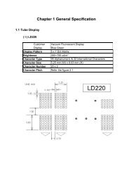
1. Parts Identification and NomenclatureENGLISHStandard ModelPrinter coverOpen this cover to load orreplace paper.Power switchUsed to turn on/offpower to the printer.Control panelFeatures LED indicatorsto indicate printerstatus and switches tooperate the printer.Cover open leverPull this lever in thedirection of the arrow toopen the printer cover.Interface connectorFor connection to ahost computer.Peripheral drive connectorConnects to peripheralunits such as cashdrawers, etc.Do not connect this to atelephone.Power connectorFor connection of the AC adapter.Never unplug the AC adapterwhile the printer is on.(For USB interface)(For parallel andEthernet interfaces)Roll paperUser’s manualFerrite coreFastener(A model with anRS-232C interfaceis not available.)(Included withParallel andEthernet model)– 1 –
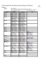
Wall Mount/Stand ModelPower switchUsed to turn on/offpower to the printer.Cover open leverPull this lever in thedirection of thearrow to open theprinter cover.ENGLISHControl panelFeatures LED indicatorsto indicate printerstatus and switches tooperate the printer.Printer coverOpen this cover to load orreplace paper.Bracket(Option)Stand(Option)Interface connectorFor connection to ahost computer.Peripheral driveconnectorConnects to peripheralunits such ascash drawers, etc.Do not connect this toa telephone.Power connectorFor connection of the AC adapter.Never unplug the AC adapter whilethe printer is on.(For USB interface)(For parallel andEthernet interfaces)Roll paperUser’s manualFerrite coreFastener(A model with anRS-232C interfaceis not available.)(Included withParallel andEthernet model)– 2 –
1-1. Choosing a place for the printerENGLISHBefore actually unpacking the printer, you should take a few minutes tothink about where you plan to use it. Remember the following pointswhen doing this.✓ Choose a firm, level surface where the printer will not be exposed tovibration.✓ The power outlet you plan to connect to for power should be nearbyand unobstructed.✓ Make sure that the printer is close enough to your host computer foryou to connect the two.✓ Make sure that the printer is not exposed to direct sunlight.✓ Make sure that the printer is well away from heaters and other sourcesof extreme heat.✓ Make sure that the surrounding area is clean, dry, and free of dust.✓ Make sure that the printer is connected to a reliable power outlet. Itshould not be on the same electric circuit as copiers, refrigerators, orother appliances that cause power spikes.✓ Make sure that the room where you are using the printer is not toohumid.1-2. Mounting hardware for wall mount modelPrecautions when mounting✓ Unplug the power cord from the outlet before starting any of thefollowing operations.✓ Select a location where the unit will not be exposed to water or impact.Make sure the wall material has sufficient width for mounting thebrackets.✓ Carefully select screws for mounting the bracket to the wall. Thesescrews must have sufficient strength to hold the printer and must belong enough to enter the wall and provide a secure mounting.Remember that we will in no way be responsible for damage resultingfrom the printer falling due to insufficient mounting strength.✓ The weight of the printer, including a roll of paper with the largestdiameter, is approximately 2.9 kg.✓ The screws for mounting the bracket must have both a shear andtensile strength capable of withstanding a load of 12 kgf (118 N) ormore. It is recommended that anchor nuts be used.✓ A screw diameter of 4 mm is recommended.– 3 –
✓ Always use all eight (8) screw holes in the mounting bracket whensecuring the mounting bracket to the wall.✓ Mount the bracket to the wall so that its mounting accuracy is withina range of ±2° perpendicular.✓ The wall used for mounting should be 90°±2° to the horizontalreference.ENGLISH1-2-1. Specifications of the wall mounting bracketWall mounting bracketouter dimensionsWall mounting bracketweight121 × 168 × 14.5 mm (Width × Height × Depth)Approx. 0.27 kg.Screws for wall mountingbracket• Not included in thepackage. The customeris to prepare the screwsthat meet the type ofwall to be used formounting.Wood structure wallConcrete wallThe eight (8) screwsused must have both ashear and tensilestrength capable ofwithstanding a load of12 kgf (118 N) or moreThe anchor nuts usedmust have both a shearand tensile strengthcapable of withstandinga load of 12 kgf(118 N) or moreUse commerciallyavailable screws thathave sufficientstrength to withstandthe weight of theprinter.1-2-2. Mounting the bracket for the wall mount model1 Make sure there is enough room forthe printer with the printer cover open,especially in front of the printer.2 As shown in the illustration to theright, place the mounting bracketagainst the wall where the printer is tobe mounted and mark the positions ofthe screw holes.3 Drill holes at the locations marked.4 Secure the bracket in place usingscrews with a diameter of 4 mm.Wall mountingbracketWall material– 4 –
Wood structure wallConcrete structure wallENGLISH• Locate the beams in thewall and mount usingthem.• Do not tighten the screwsor anchors to locationswith one wall sheet.Always make sure thatthe screws penetrate thebeams. (This is so theweight of the printer canbe supported.)• Drive the anchor nutsinto the wall and tightenthe screws.ScrewAnchor nutsBeamConcrete wallWallPosition the printer over the wall bracketand then slide it downwards to set it inplace.The printer is fixed in place by interlockingthe hook on the place attached to thebottom of the printer with the hook connectoron the bracket. It is not necessaryto secure it further with screws, etc.– 5 –
2. Consumable Parts and AC AdapterWhen consumable parts have run out, use those specified in the table below.Make sure that the AC adapter specified in the table is used.Use of consumable parts or AC adapter which are not specified in the table mayresult in damage to the printer, fire or electric shock.ENGLISH(1) Roll paper specificationThermal paperThickness: 65~150 µmWidth: 111.5±0.5 mmOuter roll diameter: ø100 mm or less+0.3Take up paper roll width: 112 -1 mmCore outer/inner diameterPaper thickness Core outer Core inner65~75 µm ø18±1 mm ø12±1 mm65~75 µm ø32±1 mm ø25.4 mm75~150 µm ø32±1 mm ø25.4 mmPrinted surface: Outer edge of rollTail end handling: Do not use paste or glue to secure the roll paper orits core.Do not fold the tail end of the paper.(2) Recommended paperMitsubishi Paper Mills LimitedP220AG (normal type paper), 65 µm (thickness)HP220A (high image stability paper), 65 µm (thickness)HP220AB-1 (high image stability paper), 75 µm (thickness)P220AB (normal type paper, card ticket), 85 µm (thickness)P220AC-1 (normal type paper, card ticket), 95 µm (thickness)P220AC (normal type paper, card ticket), 105 µm (thickness)P220AD (normal type paper, card ticket), 130 µm (thickness)P220AE-1 (normal type paper, card ticket), 150 µm (thickness)PB670 (2 color paper: Red & Black), 75 µm (thickness)PB770 (2 color paper: Blue & Black), 75 µm (thickness)Oji Paper Co., Ltd.PD150R (normal type paper), 75 µm (thickness)PD160R (high image stability paper), 65/75 µm (thickness)PD750R (2 color paper: Red & Black), 75 µm (thickness)PD700R (2 color paper: Blue & Black), 75 µm (thickness)Nippon Paper IndustriesTF50KS-E2C (normal type paper), 65 µm (thickness)– 6 –
ENGLISHKanzaki Specialty Papers Inc. (KSP)P320RB (2 color paper: Red & Black), 65 µm (thickness)P320BB (2 color paper: Blue & Black), 65 µm (thickness)Depending on the type and thickness of the paper, it may be necessary to changethe settings for printing darkness. To change the darkness settings, use theprinting darkness settings command ‘d’ n. Refer to the separateprogrammer’s manual for details.(3) AC adapter (option)Model name: PS60Input: 100 to 240 V AC, 50/60 HzOutput: DC24±5%, 2.0 A (5.0 A Load 10 sec. Max)Important!Access the following URL for the information of the recommended paper.http://www.star-m.jp/eng/dl/dl02.htm– 7 –
3. Connecting Cables and AC Adapter3-1. Interface CableNote that the interface cable is not provided. Please use a cable that meetsspecifications.ENGLISHCAUTIONBefore connecting/disconnecting the interface cable, make sure thatpower to the printer and all the devices connected to the printer is turnedoff. Also make sure the power cable plug is disconnected from the ACoutlet.3-1-1. Serial Interface (RS-232C) Cable(1)Make sure the printer is turn off.(2)Connect the interface cable to the connector on the rear panel of the printer.(3)Tighten the connector screws.Serial interface cable– 8 –
3-1-2. Parallel Interface Cable(1)Make sure the printer is turn off.ENGLISH(2)Affix the ferrite core onto the cableas shown in the illustration.Ferrite coreInterface cable5 cm(maximum)(3)Pass the fastener through the ferritecore.FastenerPull and cut(4)Loop the fastener around the cableand lock it. Use scissors to cut offany excess.– 9 –
(5)Connect the interface cable to the connector on the rear panel of the printer.(6)Fasten the connector clasps.ENGLISHParallel interface cable3-1-3. Connecting USB CableAffix the ferrite core onto the USB cable as shown in the illustration below andmake sure to pass the cable through the cable support as shown in the illustration.4 cm (maximum)Ferrite core– 10 –
3-1-4. Connecting Ethernet Cable(1)Make sure the printer is turned off.ENGLISH(2)Affix the ferrite core onto theethernet cable as shown in the illustrationbelow.Ethernet cableFerrite core(3)Pass the fastener through the ferritecore.10cm(maximum)Fastener(4)Loop the fastener around the cableand lock it. Use scissors to cut offany excess.(5)Connect the ethernet cable to theconnector on the interface board.Then, connect the other end of thecable to your computer.– 11 –
3-2. Connecting to a Peripheral UnitYou can connect a peripheral unit to the printer using a modular plug. Thefollowing describes how to make the actual connection. See “Modular plug” onpage 126 for details about the type of modular plug that is required. Note that thisprinter does not come with a modular plug or wire, so it is up to you to obtain onethat suits your needs.ENGLISHImportant!Make sure that the printer is turned off and unplugged from the AC outletand that the computer is turned off before making connections.(1)Connect the peripheral drive cable to the connector on the rear panel of theprinter.Important!Do not connect a telephone line into the peripheral drive connector.Failure to observe this may result in damage to the printer.Also, for safety purposes, do not connect wiring to the external driveconnector if there is a chance it may carry peripheral voltage.– 12 –
ENGLISH3-3. Connecting the Optional AC AdapterNote: Before connecting/disconnecting the AC adapter, make sure thatpower to the printer and all the devices connected to the printer isturned off. Also make sure the power cable plug is disconnected fromthe AC outlet.(1)Connect the AC adapter to the power cable.Note: Use only the standard AC adapter and power cable.(2)Connect AC adapter to the connector on the printer.(3)Insert the power cable plug into an AC outlet.– 13 –
3-4. Turning Power OnMake sure that the AC adapter has been connected as described in 3-3.(1)Set the power switch located on the front of the printer to on.The POWER lamp on the control panel will light up.ENGLISHPower switchImportant!We recommend that you unplug the printer from the power outletwhenever you do not plan to use it for long periods. Because of this, youshould locate the printer so that the power outlet it is plugged into isnearby and easy to access.– 14 –
4. Control Panel and Other FunctionsENGLISH4-1. Control Panel1 POWER lamp (Green LED)Lights when the power is ONPOWER ERRORFEED2 ERROR lamp (Red LED)Indicates various errors in combinationwith POWER lamp3 FEED button2 ERROR lamp(Red LED)1 POWER lamp (Green LED)3 FEED buttonPress the FEED button to feed rollpaper.4-2. Errors1) Automatically recoverable errorError DescriptionPOWER lampERROR lampRecovery ConditionsHead high temperaturedetectionFlashes at 0.5 secondintervalsOffAutomatically recovered after theprint head has cooled.Cover open errorOnOnAutomatically recovered by closingthe printer cover.2) Recoverable errorError DescriptionPaper cut errorPOWER lampOffERROR lampFlashes at 0.125second intervalsRecovery ConditionsRecovered If the cutter returns to thehome position after turning the powerOFF and ON.Note1) If the cutter doesn’t return to the home position, or doesn’t perform theinitial movement, it cannot be recovered.2) If the paper is jammed, turn the power off, clear the jammed paper, thenturn the power ON.– 15 –
3) Non recoverable errorError DescriptionRAM errorEPROM errorThermistor errorPower supply errorPOWER lampOffFlashes at 0.25second intervalsFlashes at 0.5 secondintervalsFlashes at 1 secondintervalsERROR lampOnFlashes at 0.25second intervalsFlashes at 0.5 secondintervalsFlashes at 1 secondintervalsRecovery ConditionsThis is not a recoverable error.Consult dealer for repairs.This is not a recoverable error.Consult dealer for repairs.This is not a recoverable error.Consult dealer for repairs.ENGLISHNote1) If a non recoverable error occurs, turn the power OFF immediately.2) When Power supply error occurs, there is a possibility that the powersupply unit has a trouble.For other non recoverable errors, please consult the dealer for repairs.4) Paper detection errorError Description POWER lampPaper out error OnPaper near end OnERROR lampFlashes at 0.5 secondintervalsFlashes at 2 secondintervalsRecovery ConditionsAutomatically recovered by loadinga new paper roll, then closing theprinter cover.Indicators show that the paper end isapproaching, but the printer continuesto print.– 16 –
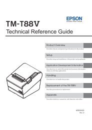
ENGLISH4-3. Self Printing(1)Test PrintingTurn the power on while holding the FEED button depressed.Test printing will be performed according to the Ver. No., DIP switch settingsand character order. When the FEED button is depressed at the time of the endof test printing, only the characters will be printed out repeatedly.– 17 –
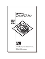
(2) Hexadecimal Dump ModeOpen the printer cover, then turn the power on while holding the FEED button.When the cover is closed, “*** HEX DUMP PRINTING ***” is printed, andthe printer enters the Hexadecimal Dump Mode.Each of the signals sent from the computer to the printer will be printed outin hexadecimal code.This function allows you to check if a control code sent to the printer by theprogram being used is correct or not. The final line is not printed if its data isless than one full line. However, if the FEED button is pushed, the final lineis printed. To turn off the mode, it is necessary to turn off the printercompletely.ENGLISH– 18 –
5. Loading the Roll PaperENGLISHBe sure to use roll paper that matches the printer’s specification.Push the Cover open lever, and openthe printer cover.Cover open leverRoll paperTension bar(Standard Model)Tension barRoll paperWhile observing the direction of theroll, set the paper roll into the hollow,and pull on the leading edge of thepaper toward you.Note 1: When you use a paper of thethickness which needs the tension bar(65 µm paper thickness
Push down both sides of the printercover to close.Note: Make sure that the printer coveris securely closed.ENGLISHImportant!1. Do not touch the cutter blade.· There is a cutter inside the paper outlet slot. Not only should you notput your hand in the paper outlet slot while printing is in progress,never put your hand into the outlet even when printing is not inprogress.· The printer cover can be opened when replacing the paper. However,since the cutter blade is on the inside of the printer cover, becareful not to place your face or hands too close to the cutter blade.2. Do not operate the cover open lever while pressing on the printercover with your hand.3. Do not pull out paper while the printer cover is closed.4. The heating element and the driver IC of the thermal head are easilydamaged. Do not touch them with metal objects, sandpaper, etc.5. During and immediately after printing, the area around the thermalhead is very hot. Do not touch it, as you could be burned.6. Printing quality may suffer if the thermal head heating elementbecomes soiled by being touched with your hands. Do not touch thethermal head heating element.7. There is a risk of damage to the driver IC of the thermal head fromstatic electricity. Please exercise caution.8. The printing quality and working life of the thermal head cannot beguaranteed if any paper other than that recommended is used. Inparticular, paper containing [Na+, K+, C1-] may drastically reducethe working life of the thermal head. Please exercise caution.9. Do not operate the printer if there is moisture on the front surface ofthe head from condensation, etc.– 20 –
6. Adjusting the Near-end SensorENGLISHUse the following procedure to adjust the near-end sensor so it is compatible withthe size of roll paper you are using.1 Open the printer cover.2 Determine the diameter of the roll paper you are using and find the requiredsetting in the table below.3 Insert the tip of a ballpoint pen or similar pointer object into the hole of theadjuster. While pressing the adjuster, slide it up or down to the setting thatmatches the roll paper you are using.Make sure the tab indicated by the arrow in the illustration is inside one of thegrooves.Level 3Level 2Level 1Important!The wall mount model can only be used at level 3, and therefore must notbe modified. Make the necessary adjustments to the standard model.– 21 –
Adjustment value according to the paper you are usingPaper thickness(µm)6575When using the paper roll with a core whose inside diameter (A):ø12, outside diameter(B):ø18Detected diameter (C)Remained paper length(Approx. mm)(Approx. m)Level 1 Level 2 Level 3 Level 1 Level 2 Level 3ø23 ø27 ø31 2.5 4.9 7.72.1 4.2 6.7ENGLISHPaper thickness(µm)65758595105130150When using the paper roll with a core whose inside diameter (A): ø25.4, outsidediameter (B):ø32Detected diameter (C)Remained paper length(Approx. mm)(Approx. m)Level 1 Level 2 Level 3 Level 1 Level 2 Level 3ø36 ø40 ø44 2.8 6.4 10.42.4 5.5 9.02.1 4.9 7.91.9 4.4 7.11.7 4.0 6.41.4 3.2 5.21.2 2.8 4.5BACNote1) The standard model is set to level 1prior to being shipped from the factory.The wall mount model is set to level3.The wall mount model can only beused at level 3, and therefore mustnot be modified.2) The C dimension and the remainedpaper length are the calculated values.There may be some variationsin actual mechanism.Roll paper coreC– 22 –
7. Preventing and Clearing Paper JamsENGLISH7-1. Preventing Paper JamsThe paper should not be touched during ejection and before it is cut.Pressing or pulling the paper during ejection may cause a paper jam, paper cuttingfailure or line feed failure.7-2. Removing Paper JamIf a paper jam occurs, clear it as described below.(1)Set the power switch to off to turn off power to the printer.(2)Pull the lever toward you to open the printer cover.(3)Remove the jammed paper.Note: Take care not to damage the printer when removing the jammed paper.Since it is easy to damage the thermal head in particular, take care notto touch it.(4)Position the roll paper straight and close the printer cover gently.Note 1: Make sure that the paper is positioned straight. If the printer coveris closed with the paper skewed, a paper jam may result.Note 2: Lock the printer cover by pressing down on the sides. Do not try toclose it by pressing down on the center. The cover may not lockproperly.(5)Set the power switch to on to turn on power to the printer. Make sure that theERROR LED is not lit.Note: While the ERROR LED is lit, the printer will not accept any commandssuch as the print command, so make sure that the printer cover is lockedproperly.– 23 –
8. Periodical CleaningPrinted characters may become partially unclear due to accumulated paper dustand dirt. To prevent such a problem, paper dust collected in the paper holder andpaper transport section and on the surface of the thermal head must be removedperiodically. Such cleaning is recommended to be carried out once six month orone million lines.ENGLISH8-1. Cleaning the Thermal HeadTo remove blackish dust collected on the surface of the thermal head, wipe it withalcohol (IPA).Note: The thermal head is easy to damage, so clean it gently with a soft cloth.Take sufficient care not to scratch it when cleaning it.8-2. Cleaning the Paper HolderUse a soft cloth to remove paper dust from the paper holder and paper transportsection.– 24 –
TABLE DES MATIERES1. Identification des pièces et nomenclature....................................................271-1. Emplacement de l’imprimante .............................................................291-2. Montage du modèle mural ...................................................................292. Consommables et adaptateur secteur ..........................................................323. Câbles de connexion et adaptateur secteur .................................................343-1. Câble d’interface ..................................................................................343-2. Raccordement d’un appareil périphérique ...........................................383-3. Connexion de l’adaptateur secteur optionnel .......................................393-4. Mise sous tension de l’imprimante ......................................................404. Panneau de commande et autres fonctions .................................................414-1. Panneau de commande .........................................................................414-2. Erreurs ..................................................................................................414-3. Auto-impression ...................................................................................435. Chargement du rouleau de papier ...............................................................456. Réglage du capteur de fin de rouleau ..........................................................477. Prévention et correction de bourrages de papier .......................................497-1. Prévention des bourrages de papier .....................................................497-2. Correction de bourrages de papier .......................................................498. Nettoyage ........................................................................................................508-1. Nettoyage de la tête d’impression ........................................................508-2. Nettoyage du support de papier ...........................................................50APPENDICE ....................................................................................................104FRANÇAISL’appendice n’est pas traduit.Pour obtenir la dernière version de ce manuel, consultez l’adresse URL suivante:http://www.star-m.jp/eng/dl/dl02.htm– 26 –
Modèle standard1. Identification des pièces et nomenclatureCapot de l’imprimanteOuvrez ce capot pour chargerou remplacer le papier.FRANÇAISInterrupteur d’alimentationPermet la mise sous ethors tension de l’appareil.Panneau des commandesLe panneau est équipé de commutateurspermettant la commande del’imprimante et de DELs indiquantles statuts.Levier d’ouverture du capotTirez ce levier dans le sens de la flèchepour ouvrir le capot de l’imprimante.Connecteurd’interfaceCe connecteurvous permet deconnecterl’imprimante àl’ordinateur-hôte.Connecteur d’appareil périphériqueCe connecteur vous permet deraccorder l’imprimante à desappareils périphériques tels que destiroirs-caisses, etc.Ne pas raccorder à un téléphone.Connecteurd’alimentationCe connecteur vouspermet de connecterle câble de l’adaptateursecteur. Nedéconnectez pas lecâble lorsquel’imprimante est soustension.(Pour interface USB)Rouleau de papierMode d’emploi(Pour interfacesparallèles et Ethernet)Tore de ferrite(Aucun élémentdisponible pourinterface RS-232C)– 27 –Attache(Incluse avec le modèlepour interfacesparallèle et Ethernet)
Modèle mural/avec socleLevier d’ouverture du capotTirez ce levier dans le sens dela flèche pour ouvrir le capotde l’imprimante.Interrupteur d’alimentationPermet la mise sous ethors tension de l’appareil.Panneau des commandesLe panneau est équipé decommutateurs permettant lacommande de l’imprimante etde DELs indiquant les statuts.Capot de l’imprimanteOuvrez ce capot pour chargerou remplacer le papier.FRANÇAIS<strong>Support</strong>(en option)Socle(en option)Connecteurd’interfaceCe connecteurvous permet deconnecterl’imprimante àl’ordinateur-hôte.Connecteur d’appareilpériphériqueCe connecteur vous permetde raccorder l’imprimante àdes appareils périphériquestels que des tiroirs-caisses,etc.Ne pas raccorder à untéléphone.Connecteur d’alimentationCe connecteur vous permet de connecterle câble de l’adaptateur secteur. Nedéconnectez pas le câble lorsque l’imprimanteest sous tension.(Pour interface USB)Rouleau de papierMode d’emploi(Pour interfacesparallèles et Ethernet)Tore de ferrite(Aucun élémentdisponible pourinterface RS-232C)– 28 –Attache(Incluse avec le modèlepour interfacesparallèle et Ethernet)
FRANÇAIS1-1. Emplacement de l’imprimanteAvant de déballer l’imprimante, déterminez l’emplacement où voussouhaitez l’installer. Veuillez observer les points ci-dessous lors de votrechoix.✓ Choisissez une surface stable et de niveau sur laquelle l’imprimantene sera exposée à aucune vibration.✓ Assurez-vous que l’emplacement dispose d’une prise secteur procheet d’accès aisé.✓ Assurez-vous que la distance entre l’imprimante et l’ordinateur-hôtevous permet de les raccorder aisément.✓ Assurez-vous que l’imprimante n’est pas exposée directement auxrayons du soleil.✓ Tenez l’imprimante à l’écart des sources de chaleur importante, tellesque les appareils de chauffage, etc.✓ Assurez-vous que le lieu où vous souhaitez installer l'imprimante estpropre, sec et n'est pas poussiéreux.✓ Assurez-vous que la prise secteur à laquelle vous raccordez l’imprimantedélivre une tension stable. Evitez de raccorder l’imprimante àla prise secteur d’un circuit alimentant de gros consommateurs decourant, tels qu’un photocopieur, réfrigérateur, etc.✓ Assurez-vous que le lieu où vous installez l’imprimante n’est pasexcessivement humide.1-2. Montage du modèle muralPrécautions à prendre avant le montage✓ Débranchez le câble d’alimentation du secteur avant d’effectuer touttravail expliqué dans cette section.✓ Choisissez un emplacement où l’appareil ne risque pas d’être mouilléni de subir des chocs. Assurez-vous que l’épaisseur du mur soitsuffisante pour le montage des supports.✓ Sélectionnez soigneusement les vis de montage du support. Ces visdoivent avoir la robustesse nécessaire et être de longueur suffisanteafin d’assurer le maintien solide de l’imprimante. Le fabricant déclinefermement toute responsabilité pour tout dommage subi parl’imprimante en cas d’une chute due à un montage incorrect.✓ Le poids de l’imprimante, comprenant un rouleau de papier dudiamètre le plus grand, est d’environ 2,9 kg.✓ Les vis de montage du support doivent avoir une résistance aucisaillement et à la traction de 12 kgf (118 N) minimum. L’utilisationd’écrous d’ancrage est recommandée.– 29 –
✓ Le diamètre de vis recommandé est de 4 mm.✓ Veillez toujours à utiliser les huit (8) orifices de vis du support demontage.✓ Montez le support au mur en veillant à ce sa position ne diffère quede ±2° maximum de la verticale.✓ Le mur destiné à recevoir l’appareil doit être à un angle de 90°±2° parrapport à l’horizontale.1-2-1. Caractéristiques du support muralDimensions extérieures dusupport mural121 × 168 × 14,5 mm (largeur × hauteur × profondeur)FRANÇAISPoids du support muralEnviron 0,27kgVis du support mural• Non livrées avecl’appareil. Il convient dese procurer les visconvenant au type demur utilisé.Mur en boisLes vis de montage dusupport doivent avoirune résistance aucisaillement et à latraction de 12 kgf(118 N) minimum.Les écrous d’ancrageutilisés avoir unerésistance aucisaillement et à latraction de 12 kgf(118 N) minimum.Utilisez des visvendues dans lecommerce capables desupporter le poids del’imprimante.Mur en béton1-2-2. Mise en place du support mural1 Veillez à ce que l’espace disponiblesoit suffisant pour l’imprimante capotouvert, particulièrement à l’avant del’appareil.2 Conformément à l’illustration cicontre,disposer le support muralcontre le mur, à l’emplacement exactde l’imprimante, et marquer d’unrepère la position des trous de foragepour les vis.3 Forer des trous aux endroits indiqués.4 Mettre le support en place à l’aide devis d’un diamètre de 4 mm.<strong>Support</strong> muralMur– 30 –
Mur en boisMur en bétonFRANÇAIS• Montez les vis dans lacharpente d’un mur.• Ne pas serrer les vis oules ancrages dans lacloison seule. Veillezbien à les monter dans unpoteau de la charpente,ceci afin d’assurer que lesvis puissent supporter lepoids de l’imprimante.• Monter les écrousd’ancrage dans le mur etserrer les vis.VisÉcrous d’ancragePoteauMur en bétonCloisonDisposer l’imprimante légèrement audessusdu support et la faire glisser versle bas. L’imprimante se fixe au mur grâceaux deux crochets figurant à la base del’appareil et qui viennent s’encastrer dansles réceptacles du support mural. Il n’estpas nécessaire de renforcer davantage àl’aide de vis ou d’autres moyens.– 31 –
2. Consommables et adaptateur secteurIl convient d’utiliser exclusivement les types de papier figurant dans le tableau cidessous.Veillez également à utiliser l’adaptateur secteur qui figure dans le tableau.L’utilisation d’un type de papier et d’adaptateur ne figurant pas dans le tableau risqued’endommager l’imprimante, de causer un incendie ou une décharge électrique.(1) Rouleau de papier, caractéristiquesPapier thermiqueÉpaisseur: 65~150 µmLargeur: 111,5±0,5 mmDiamètre extérieur du rouleau: ø100 mm or less+0,3Largeur du rouleau de papier: 112 -1 mmDiamètre extérieur/intérieur du support de rouleauÉpaisseur du papier Extérieur du support de rouleau Intérieur du support de rouleau65~75 µm ø18±1 mm ø12±1 mm65~75 µm ø32±1 mm ø25,4 mm75~150 µm ø32±1 mm ø25,4 mmSurface imprimée: Bord extérieur du rouleauExtrémité arrière: Ne pas utiliser de colle pour immobiliser le rouleaude papier ou son noyau.Ne pas plier l’extrémité arrière du papier.(2) Papier conseilléMitsubishi paper mills limitedP220AG (papier de type normal), 65 µm (épaisseur)HP220A (papier à stabilité d’image élevée), 65 µm (épaisseur)HP220AB-1 (papier à stabilité d’image élevée), 75 µm (épaisseur)P220AB (papier de type normal, ticket), 85 µm (épaisseur)P220AC-1 (papier de type normal, ticket), 95 µm (épaisseur)P220AC (papier de type normal, ticket), 105 µm (épaisseur)P220AD (papier de type normal, ticket), 130 µm (épaisseur)P220AE-1 (papier de type normal, ticket), 150 µm (épaisseur)PB670 (papier 2 couleurs : rouge et noir), 75 µm (épaisseur)PB770 (papier 2 couleurs : bleu et noir), 75 µm (épaisseur)Oji paper Co., Ltd.PD150R (papier de type normal), 75 µm (épaisseur)PD160R (papier à stabilité d’image élevée), 65/75 µm (épaisseur)PD750R (papier 2 couleurs : rouge et noir), 75 µm (épaisseur)PD700R (papier 2 couleurs : bleu et noir), 75 µm (épaisseur)Nippon paper industriesTF50KS-E2C (papier de type normal), 65 µm (épaisseur)FRANÇAIS– 32 –
FRANÇAISKanzaki Specialty Papers Inc. (KSP)P320RB (papier 2 couleurs : rouge et noir), 65 µm (épaisseur)P320BB (papier 2 couleurs : bleu et noir), 65 µm (épaisseur)Suivant le type et l’épaisseur du papier, il peut être nécessaire de changer leréglage de clarté d’impression. Pour changer le réglage de la clarté d’impression,utilisez la commande de réglage de clarté d’impression ‘d’n.Reportez-vous au manuel de programmation séparé pour les détails.(3) Adaptateur secteur (option)Nom du modèle: PS60Entrée: CA100 à 240 V, 50/60 HzSortie: CC24±5%, 2,0 A (charge de 10 sec à 5,0 A max.)Attention!Pour obtenir des informations concernant le papier recommandé, consultezl’adresse URL suivante : http://www.star-m.jp/eng/dl/dl02.htm– 33 –
3. Câbles de connexion et adaptateur secteur3-1. Câble d’interfaceLe câble d’interface n’est pas livré. Veuillez utiliser un câble conforme auxcaractéristiques.ATTENTIONAvant de connecter ou déconnecter le câble d’interface, veillez à ce quel’imprimante et tous les appareils qui y sont connectés soient horstension. Veillez également à débrancher le câble d’alimentation de laprise secteur.FRANÇAIS3-1-1. Câble d’interface série (RS-232C)(1)Assurez-vous que l’imprimante est hors tension.(2)Connectez le câble d’interface à la borne figurant sur le panneau arrière del’imprimante.(3)Serrez les vis du connecteur.Câble d’interface série– 34 –
FRANÇAIS3-1-2. Interface parallèleTore de ferrite(1)Assurez-vous que l’imprimante esthors tension.(2)Fixez la grande gaine en ferrite surle câble comme illustré.Interface câble5 cm(maximum)Attache(3)Passez l’attache dans le tore de ferrite.Tirez et coupez(4)Passez l’attache autour du tore deferrite et serrez-la. Coupez l’extrémitéde l’attache à l’aide de ciseaux.– 35 –
(5)Connectez le câble d’interface à la borne figurant sur le panneau arrière del’imprimante.(6)Attachez les fermoirs du connecteur.Câble d’interface parallèleFRANÇAIS3-1-3. Branchement d’un câble USBAttachez le tore de ferrite au câble USB conformément à l’illustration ci-dessous,et veiller à passer le câble par le support de câble illustré.4 cm (maximum)Tore de ferrite– 36 –
3-1-4. Branchement d’un câble ethernet(1)Assurez-vous que l’imprimante esthors tension.FRANÇAIS(2)Attachez le tore de ferrite au câbleethernet conformément à l’illustration.Tore de ferriteCâble ethernet(3)Passez le collier de serrage par letore de ferrite.10 cm(maximum)Collier de serrage(4)Passez le collier de serrage autourdu câble et immobilisez ce dernier.Coupez l’extrémité excédentaire ducollier à l’aide d’une paire de ciseaux.(5)Branchez le câble ethernet au connecteurde la carte interface et àvotre ordinateur.– 37 –
3-2. Raccordement d’un appareil périphériqueVous pouvez raccorder un appareil périphérique à l’imprimante à l’aide d’unefiche modulaire. Nous expliquons ci-dessous comment faire le raccordementproprement dit. Pour les détails sur le type de fiche modulaire à utiliser, reportezvousà la page 126. Notez que le fil ou la fiche modulaires ne sont pas fournis avecl’imprimante. Vous devrez donc vous les procurer.Attention!Assurez-vous que l’imprimante est hors tension, qu’elle est débranchéede la prise secteur et que l’ordinateur est hors tension avant d’effectuerles connexions.FRANÇAIS(1)Connectez le câble de pilote de périphérique à la borne figurant sur le panneauarrière de l’imprimante.Attention!Ne connectez pas une ligne de téléphone à la borne du pilote depériphérique, sous peine de risquer d’endommager l’imprimante.Pour des raisons de sécurité, il convient également de ne pas brancherd’appareil périphérique en cas de risque de survoltage.– 38 –
3-3. Connexion de l’adaptateur secteur optionnelRemarque:Avant de connecter ou déconnecter l’adaptateur secteur, veillezà ce que l’imprimante et tous les appareils qui y sont connectéssoient hors tension. Veillez également à débrancher le câbled’alimentation de la prise secteur.FRANÇAIS(1)Connectez l’adaptateur secteur au câble d’alimentation.Remarque:Utilisez exclusivement l’adaptateur secteur et le câble d’alimentationdestinés à l’imprimante.(2)Connectez l’adaptateur secteur à la borne de l’imprimante.(3)Branchez la prise du câble d’alimentation à la prise secteur.– 39 –
3-4. Mise sous tension de l’imprimanteAssurez-vous d’avoir bien connecté l’adaptateur secteur comme décrit à lasection 3-3.(1)Placez l’interrupteur d’alimentation, situé à l’avant de l’imprimante, sur laposition sous tension.La DEL POWER s’allume au panneau des commandes.FRANÇAISInterrupteurd’alimentationAttention!Nous vous recommandons de débrancher l’imprimarte du secteur lorsquevous ne comptez pas l’utiliser pendant une période prolongée. Parailleurs, veillez lors de l’installation à ce que la prise secteur alimentantl’imprimante soit proche et d’accès facile.– 40 –
4. Panneau de commande et autres fonctionsFRANÇAIS4-1. Panneau de commandePOWER ERROR FEED1 Témoin POWER (DEL verte)S’allume quand l’appareil est soustension.2 Témoin ERROR (DEL rouge)Indique des erreurs variées en combinaisonavec le témoin POWER.3 Témoin FEED(avance de papier)2 Témoin ERROR (erreur)1 Témoin POWER (alimentation)3 Témoin FEEDAppuyez sur la touche FEED pourfaire avancer le papier.4-2. Erreurs1) Erreur récupérable automatiquementDescription de l’erreurDétection de températureélevée de latêteErreur d’ouverturedu capot de l’imprimanteTémoin POWERClignote à 0,5 seconded’intervalleSous tensionTémoin ERRORHors tensionSous tensionConditions de récupérationRécupération automatique après refroidissementde la tête.Récupération automatique après fermeturedu capot de l’imprimante.2) Erreur récupérableDescription de l’erreurErreur de découpedu papierTémoin POWERHors tensionTémoin ERRORClignote à 0,125seconde d’intervalleConditions de récupérationRécupération si l’unité de découpagerevient dans sa position d’origineaprès la mise hors tension etsous tension.Remarque1) Si l’unité de découpage ne revient pas dans sa position d’origine oun’effectue pas le mouvement initial, la récupération est impossible.2) Si le papier est coincé, mettez l’appareil hors tension, dégagez le bourragede papier, puis mettez l’appareil sous tension.– 41 –
3) Erreur non récupérableDescription de l’erreurErreur de mémoireviveErreur d’EPROMErreur de thermistorErreur d’alimentationTémoin POWERHors tensionClignote à 0,25 seconded’intervalleClignote à 0,5 seconded’intervalleClignote à 1 seconded’intervalleTémoin ERRORSous tensionClignote à 0,25 seconded’intervalleClignote à 0,5 seconded’intervalleClignote à 1 seconded’intervalleConditions de récupérationCe n’est pas une erreur récupérable.Consultez votre revendeur pour desréparations.Ce n’est pas une erreur récupérable.Consultez votre revendeur pour desréparations.Ce n’est pas une erreur récupérable.Consultez votre revendeur pour desréparations.Remarque1) Si une erreur non récupérable se produit, mettez immédiatement l’appareilhors tension.2) Quand une erreur d’alimentation se produit, il est possible que le blocd’alimentation soit en panne.Pour d’autres erreurs non récupérable, veuillez consulter votre revendeurpour des réparations.FRANÇAIS4) Erreur de détection de papierDescription de l’erreurErreur de sortie depapierLe rouleau de papierest presque terminéTémoin POWERSous tensionSous tensionTémoin ERRORClignote à 0,5 seconded’intervalleClignote à 2 seconded’intervalleConditions de récupérationRécupération automatique aprèschargement d’un nouveau rouleaude papier et fermeture du capot del’imprimante.Les indicateurs signalent la fin prochedu rouleau, mais l’imprimantecontinue à imprimer.– 42 –
FRANÇAIS4-3. Auto-impression(1)Essai d’impressionMettez l’appareil sous tension tout en maintenant la touche FEED enfoncée.L’essai d’impression sera effectué en fonction du numéro de version, desréglages du commutateur DIP et de l’ordre des caractères. Si vous appuyez surla touche FEED à la fin de l’essai d’impression, seuls les caractères serontimprimés à plusieurs reprises.– 43 –
(2) Mode de vidage hexadécimalOuvrez le capot de l’imprimante, puis mettez l’appareil sous tension tout enmaintenant la touche FEED enfoncée. Quand le capot est fermé, “*** HEXDUMP PRINTING ***” est imprimé et l’imprimante entre en mode de vidagehexadécimal.Chacun des signaux envoyés par l’ordinateur à l’imprimante sera imprimédans le code hexadécimal.Cette fonction vous permet de vérifier si un code de commande envoyé àl’imprimante par le programme utilisé est correct ou non. La ligne finale n’estpas imprimée si ses données sont inférieures à une ligne complète. Néanmoins,si vous appuyez sur la touche FEED, la ligne finale sera imprimée. Pourdésactiver ce mode, il est nécessaire de mettre l’imprimante complètementhors tension.FRANÇAIS– 44 –
5. Chargement du rouleau de papierVeillez à utiliser un rouleau de papier qui correspond aux spécifications del’imprimante.FRANÇAISPoussez le levier d’ouverture du capotet ouvrez le capot de l’imprimante.Levier d’ouverture du capotRouleau de papierBarre de tension(Modèle standard)Barre de tensionRouleau de papìer(Modèle mural/avec socle)– 45 –Mettez le rouleau de papier en placedans le creux tout en respectant sonorientation, et tirez sur l’extrémité dupapier.Remarque 1: Quand vous utilisez unpapier dont l’épaisseur rend nécessairel’utilisation de la barre de tension (65µm épaisseur du papier
Poussez vers la bas les deux côtés ducapot de l’imprimante pour le fermer.Remarque: Assurez-vous que le capotde l’imprimante est bien fermé.Attention!1. Ne pas toucher la lame du coupe-ruban.· Une lame se trouve dans la fente de sortie de papier. Il est fortementdéconseillé de mettre sa main dans la fente de sortie de papier nonseulement pendant l’impression mais aussi en toute autre circonstance,même quand l’impression n’est pas effectuée.· Le capot de l’imprimante peut être ouvert pour remplacer le papier.Néanmoins, la lame du coupe-ruban se trouvant à l’intérieur ducapot de l’imprimante, veuillez faire attention à ne pas rapprochervotre figure ou vos mains trop près de la lame du coupe-ruban.2. Ne pas faire fonctionner le levier d’ouverture du capot tout enappuyant sur le capot de l’imprimante avec la main.3. Ne pas tirer sur le papier pour le faire sortir quand le capot del’imprimante est fermé.4. L’élément de chauffage et le circuit imprimé de la tête d’impressionthermique sont facilement endommagés. Ne pas les toucher avec desobjets métalliques, du papier de verre, etc.5. Pendant et immédiatement après l’impression, la zone autour de latête d’impression thermique est très chaude. Ne pas la toucher carvous pourriez vous brûler.6. La qualité d’impression peut être affectée si l’élément de chauffage dela tête d’impression thermique est souillé par un contact avec vosmains, Ne pas toucher l’élément de chauffage de la tête d’impressionthermique.7. Le circuit imprimé de la tête d’impression thermique peut être endommagépar l’électricité statique. Veuillez prendre des précautions.8. La qualité d’impression et la durée de vie utile de la tête d’impressionthermique ne peuvent pas être garanties si un papier quelconquedifférent de celui recommandé est utilisé. En particulier, le papiercontenant les éléments suivants: NA+, K+, C1-, peut réduire de façonimportante la durée de vie utile de la tête d’impression thermique.Veuillez prendre des précautions.9. Ne pas faire fonctionner l’imprimante si de l’humidité provenant dela condensation, etc., est présente sur la surface avant de la tête.– 46 –FRANÇAIS
6. Réglage du capteur de fin de rouleauUtilisez la procédure suivante pour régler le capteur de fin de rouleau conformémentà la taille du rouleau de papier utilisé.FRANÇAIS1 Ouvrez le capot de l’imprimante.2 Déterminez le diamètre du rouleau de papier utilisé et identifiez le réglagerequis dans le tableau ci-dessous.3 Insérez la pointe d’un stylo bille ou un autre instrument pointu similaire dansle trou du curseur de réglage. Tout en appuyant sur le curseur de réglage,faites-le glisser vers le haut ou le bas jusqu’au réglage correspondant aurouleau de papier utilisé.Assurez-vous que l’ergot indiqué par la flèche dans l’illustration se trouve àl’intérieur d’une des nervures.Niveau 3Niveau 2Niveau 1Attention!Le niveau est ajustable uniquement pour le modèle standard. Le modèlemural fonctionne exclusivement sur le niveau 3 et celui-ci ne doit doncpas être modifié.– 47 –
Valeur de réglage correspondant au papier utilisé.Épaisseur dupapier (µm)6575Épaisseur dupapier (µm)65758595105130150Quand vous utilisez un rouleau de papier dont le diamètre intérieur du support est de(A):ø12 et le diamètre extérieur de (B):ø18Diamètre détecté (C)Longueur de papier restante(Env. mm)(Env. m)Niveau 1 Niveau 2 Niveau 3 Niveau 1 Niveau 2 Niveau 3ø23 ø27 ø31 2,5 4,9 7,72,1 4,2 6,7Quand vous utilisez un rouleau de papier dont le diamètre intérieur du support est de(A):ø25,4 et le diamètre extérieur de (B):ø32Diamètre détecté (C)Longueur de papier restante(Env. mm)(Env. m)Niveau 1 Niveaul 2 Niveau 3 Niveau 1 Niveau 2 Niveau 3ø36 ø40 ø44 2,8 6,4 10,42,4 5,5 9,02,1 4,9 7,91,9 4,4 7,11,7 4,0 6,41,4 3,2 5,21,2 2,8 4,5FRANÇAISBACMandrin durouleau de papierCRemarque1) Le curseur de réglage du modèlestandard est réglé sur le niveau 1 enusine.Le curseur de réglage du modèlemural est réglé sur le niveau 3 enusine.Le niveau du modèle mural ne doitpas être modifié, car il fonctionneexclusivement sur le niveau 3.2) La dimension C et la longueur depapier restante sont les valeurs calculées.Il est possible qu’il y aitquelques différences dans le mécanismeactuel.– 48 –
7. Prévention et correction de bourrages de papierFRANÇAIS7-1. Prévention des bourrages de papierIl convient de ne jamais toucher le papier pendant son éjection et avant qu’il soitcoupé. Appuyer ou tirer sur le papier pendant son éjection risque de provoquerun bourrage, des problèmes de coupure ou d’avance de ligne.7-2. Correction de bourrages de papierEn cas de bourrage de papier, procédez comme suit afin d’y remédier :(1)Mettez l’appareil hors tension.(2)Tirez le levier tout à fait vers le bas afin d’ouvrir le capot de l’imprimante.(3)Retirez le papier bloqué.Remarque:Veillez à ne pas endommager l’imprimante lors du retrait dupapier bloqué.Veillez particulièrement à ne pas toucher la tête d’impressionthermique en raison de sa fragilité.(4)Veillez à insérer le rouleau de papier tout droit et refermez avec soin le capotde l’imprimante.Remarque 1: Le papier doit être placé bien droit. Si vous refermez le capotde l’imprimante alors que le papier est de travers (voirillustration), un bourrage peut se produire.Remarque 2: Verrouillez le capot de l’imprimante en appuyant sur lescôtés. Ne pas essayer de refermer le capot en appuyant surson centre. Le capot pourrait ne pas se verrouiller correctement.(5)Mettez l’imprimante sous tension. Assurez-vous que la DEL ERROR n’estpas allumée.Remarque:Tant que la DEL ERROR est allumée, l’imprimante n’accepteaucune commande. Il faut donc veiller à ce que le capot del’imprimante soit verrouillé.– 49 –
8. NettoyageLes caractères imprimés pourraient devenir partiellement illisibles en raison del’accumulation de la poussière de papier et de crasse. Afin de prévenir ce genrede problème, il convient de nettoyer régulièrement la poussière qui s’accumulesur le support de papier, les passages du papier et la surface de la tête d’impression.Il est recommandé d’effectuer un tel nettoyage une fois tous les six mois ouaprès l’impression d’un million de lignes.8-1. Nettoyage de la tête d’impressionNettoyez la poussière noirâtre accumulée sur la surface de la tête d’impression àl’alcool isopropylique.Remarque:La tête d’impression thermique est fragile, il convient donc deprocéder avec précaution. Prenez soin de ne pas la griffer.FRANÇAIS8-2. Nettoyage du support de papierNettoyez la poussière de papier accumulée sur le support de papier et sur lespassages du papier à l’aide d’un chiffon doux.– 50 –
INHALTSVERZEICHNIS1. Beschreibung und Bezeichnung der Geräteteile .........................................531-1. Wahl eines Aufstellungsorts für den Drucker ......................................551-2. Anbringungsteile für Wandanbringungsmodell ...................................552. Verbrauchsteile und Netzteil ........................................................................583. Anschlußkabel und Netzteil ..........................................................................603-1. Schnittstellenkabel ...............................................................................603-2. Anschluß an ein Peripheriegerät ..........................................................643-3. Anschließen des optionalen Netzteils ..................................................653-4. Einschalten ...........................................................................................664. Bedienfeld und andere Funktionen ..............................................................674-1. Bedienfeld ............................................................................................674-2. Fehler ...................................................................................................674-3. Selbstdruck ...........................................................................................695. Einlegen der Papierrolle ...............................................................................716. Einstellung des Endanäherungs-Sensors .....................................................737. Verhindern und Beheben von Papierstau ...................................................757-1. Verhindern von Papierstau ...................................................................757-2. Beheben von Papierstau .......................................................................758. Regelmäßige Reinigung.................................................................................768-1. Reinigen des Thermalkopfes................................................................768-2. Reinigen des Papierhalters ...................................................................76ANHANG .........................................................................................................104DEUTSCHDer Anhand dieser Bedienungsanleitung ist nur in englischer Sprache.Bitte wenden Sie sich an die folgende Internet-Address:http://www.star-m.jp/eng/dl/dl02.htmwenn Sie die neueste Revision dieses Handbuches lesen möchten.BETRIEBSGERÄUSCHMaschinenIärminformationsverordnung 3.GSGV, 18.01.1991:Der arbeitsplatzbezogene Schalldruckpegel beträgt 70 dB (A)oder weniger gemäß ISO 7779.– 52 –
1. Beschreibung und Bezeichnung der GeräteteileStandard-ModellAbdeckungDiese Abdeckung öffnen, um Papiereinzusetzen oder zu entnehmen.Nur Parallel-Schnittschnelle-ModellZum Ein- oder Ausschaltendes Druckers.DEUTSCHBedienfeldMit LED-Anzeigen zurAnzeige des Druckerstatusund Schalter zurDruckerbedienung.Abdeckung-öffnen-HebelDiesen Hebel in Pfeilrichtung ziehen, umdie Druckerabdeckung zu öffnen.SchnittstellenbuchseZum Anschließen anden Hostcomputer.Peripherie-TreiberanschlußZum Anschluß anPeripheriegeräte wieRegistrierkassen etc.Nicht zum Anschluß anein Telefon!BetriebsstromanschlußZum Anschließen desBetriebsstromkabels vomNetzteil. Den Stecker nichtbei eingeschaltetem Druckerabziehen.(für USB-Schnittstelle)Rollenpapier(für parallele undEthernet-Schnittstelle)BedienungsanleitungFerritkern(Für die RS-232C-Schnittstelle ist keinElement erhältlich.)– 53 –Befestigungsband(mit dem ParallelundEthernet-Modell geliefert)
Wandanbringungs-/StandmodellNur Parallel-Schnittschnelle-ModellZum Ein- oder Ausschaltendes Druckers.Abdeckung-öffnen-HebelDiesen Hebel in Pfeilrichtungziehen, um die Druckerabdeckungzu öffnen.BedienfeldMit LED-Anzeigen zurAnzeige des Druckerstatusund Schalter zur Druckerbedienung.AbdeckungDiese Abdeckung öffnen, umPapier einzusetzen oder zuentnehmen.DEUTSCHBügel(Option)Ständer(Option)SchnittstellenbuchseZum Anschließen anden Hostcomputer.Peripherie-TreiberanschlußZum Anschluß anPeripheriegeräte wieRegistrierkassen etc.Nicht zum Anschluß anein Telefon!BetriebsstromanschlußZum Anschließen des Betriebsstromkabelsvom Netzteil. Den Stecker nicht beieingeschaltetem Drucker abziehen.(für USB-Schnittstelle)Rollenpapier(für parallele undEthernet-Schnittstelle)Bedienungsanleitung Ferritkern(Für die RS-232C-Schnittstelle ist keinElement erhältlich.)– 54 –Befestigungsband(mit dem ParallelundEthernet-Modell geliefert)
DEUTSCH1-1. Wahl eines Aufstellungsorts für den DruckerBevor Sie den Drucker auspacken, sollten Sie einige Minuten damitverbringen, einen geeigneten Aufstellungsort auszusuchen. Denken Siedabei an die folgenden Punkte:✓ Den Drucker auf einem flachen, aber festen Untergrund aufstellen,wo keine Vibrationen vorhanden sind.✓ Die verwendete Steckdose soll in der Nähe und frei zugänglich sein.✓ Sicherstellen, daß der Drucker nahe genug am Computer ist, um dieGeräte mit dem Druckerkabel verbinden zu können.✓ Sicherstellen, daß der Drucker vor direktem Sonnenlicht geschützt ist.✓ Sicherstellen, daß der Drucker ausreichend weit von Heizkörpernentfernt steht.✓ Dafür sorgen, daß die Umgebung des Druckers sauber, trocken undstaubfrei ist.✓ Sicherstellen, daß der Drucker an eine einwandfreie Stromzufuhrangeschlossen ist. Er sollte nicht an Steckdosen angeschlossen werden,an denen bereits Geräte mit möglichen Netzstörungen wieKopierer, Kühlschränke u.a. angeschlossen sind.✓ Den Drucker nicht an Orten mit hoher Luftfeuchtigkeit aufstellen.1-2. Anbringungsteile für WandanbringungsmodellVorsichtsmaßregeln bei der Anbringung✓ Vor den folgenden Arbeiten muß immer der Stecker aus der Steckdosegezogen werden.✓ Einen Anbringungsort wählen, wo das Gerät vor Wasser und Stößengeschützt ist. Sicherstellen, daß das Wandmaterial stark genug zumAnbringen der Haltebügel ist.✓ Vorsichtig die Schrauben zum Anbringen des Haltebügels an derWand auswählen. Diese Schrauben müssen ausreichende Stärke zumHalten des Druckers haben und müssen lang genug sein, um in dieWand einzudringen und einen sicheren Halt zu gewährleisten. DenkenSie daran, daß der Hersteller in keiner Weise für Schädenverantwortlich ist, die durch Herunterfallen des Druckers aufgrundunzureichender Befestigungsstärke verursacht werden.✓ Das Gewicht des Druckers einschließlich einer Rolle Papier mit demgrößten Durchmesser beträgt etwa 2,9 kg.✓ Die Schrauben zum Anbringen des Bügels müssen eine Bruch- undZugfestigkeit haben, die einer Last von 12 kg-f (118 N) oder mehrentspricht. Es wird empfohlen, Ankermuttern zu verwenden.✓ Ein Schraubendurchmesser von 4 mm wird empfohlen.– 55 –
✓ Immer alle acht (8) Schraubenlöcher im Haltebügel verwenden,wenn der Haltebügel an der Wand angebracht wird.✓ Den Bügel so an der Wand anbringen, daß die Befestigungsgenauigkeitinnerhalb von ±2° in lotrechter Richtung liegt.✓ Die zur Befestigung verwendete Wand muß innerhalb von 90°±2°zur horizontalen Referenz angeordnet sein.1-2-1. Spezifikationen des WandhaltebügelsAußenabmessungen desWandhaltebügels121 × 168 × 14,5 mm (Breite × Höhe × Tiefe)Gewicht desWandhaltebügelsSchrauben fürWandhaltebügel• Nicht im Satz enthalten.Der Kunde ist für dieBeschaffung vonSchraubenverantwortlich, die derzur Anbringungverwendeten Wandentsprechen.Ca. 0,27 kgHolzstrukturwandBetonwandDie acht (8) verwendetenSchrauben müssen eineBruch- und Zugfestigkeithaben, die einer Last von12 kg-f (118 N) odermehr entspricht.Die verwendetenAnkermuttern müsseneine Bruch- undZugfestigkeit haben,die einer Last von 12kg-f (118 N) odermehr entspricht.Es werden imFachhandel erhältlicheSchrauben verwendet,die eine ausreichendeStärke für dasGewicht des Druckershaben.DEUTSCH1-2-2. Anbringen des Bügels für Wandanbringungsmodell1 Sicherstellen, daß ausreichend Platz fürden Drucker mit geöffneter Abdeckungvorhanden ist, insbesondere vor demDrucker.2 Wie in der Abbildung rechts gezeigt wirdder Haltebügel gegen die Wand gedrückt,wo der Drucker angebracht werden soll,und die Positionen der Schraubenlöcherwerden mit einem Stift markiert.3 An den gekennzeichneten Stellen Löcherbohren.4 Den Bügel mit geeigneten Schraubenmit einem Durchmesser von 4 mmbefestigen.WandmaterialWandhaltebügel– 56 –
HolzstrukturwandBetonstrukturwandDEUTSCH• Die Balken in der Wandaufsuchen und zurBefestigung verwenden.• Nicht die Schrauben oderAnker an Stellenbefestigen, wo keineBalken unter derWandverkleidung sind.Immer sicherstellen, daßdie Schrauben in dieBalken eindringen. (Diesist erforderlich, damit dasGewicht des Druckersgetragen werden kann.)Schraube• Die Ankermuttern in dieWand treiben, und dieSchrauben befestigen.AnkermutternBalkenBetonwandWandDen Drucker über den Wandhaltebügelsetzen, wie in der Abbildung gezeigt,und nach unten schieben. Die Befestigunggeschieht, indem der Hakenteil derHalteplatte mit dem unteren Teil desDruckergehäuses eingreift. WeitereBefestigung mit Schrauben oder anderenTeilen ist nicht erforderlich.– 57 –
2. Verbrauchsteile und NetzteilWenn die Verbrauchsteile verbraucht sind, besorgen Sie Ersatz entsprechend derunten gezeigten Tabelle.Verwendung von Verbrauchsteilen oder Netzteilen, die nicht den unten aufgeführtenBeschreibungen entsprechend, kann zu Schäden am Drucker, Brändenoder elektrischen Schlägen führen.(1) RollenpapierbeschreibungThermopapierDicke: 65~150 µmBreite: 111,5±0,5 mmRollen-Außendurchmesser: ø100 mm or less+0,3Breite der Aufnehmerpapierrolle: 112 -1 mmKern Außen/Innen-DurchmesserPapierdicke Kern außen Kern innen65~75 µm ø18±1 mm ø12±1 mm65~75 µm ø32±1 mm ø25,4 mm75~150 µm ø32±1 mm ø25,4 mmDruckfläche: Äußere PapierkanteBehandlung der Papierendkante:Nicht Paste oder Kleber zum Befestigenvon Papierrolle oder Kern verwenden.Nicht die Papierendkante falten.(2) Empfohlenes PapierMitsubishi Paper Mills Ltd.P220AG (Normalpapier), 65 µm (Dicke)HP220A (Papier für hochstabile Bilder), 65 µm (Dicke)HP220AB-1 (Papier für hochstabile Bilder), 75 µm (Dicke)P220AB (Normalpapier, Kartenticket), 85 µm (Dicke)P220AC-1 (Normalpapier, Kartenticket), 95 µm (Dicke)P220AC (Normalpapier, Kartenticket), 105 µm (Dicke)P220AD (Normalpapier, Kartenticket), 130 µm (Dicke)P220AE-1 (Normalpapier, Kartenticket), 150 µm (Dicke)PB670 (Bicolor-Papier: Rot & Schwarz), 75 µm (Dicke)PB770 (Bicolor-Papier: Blau & Schwarz), 75 µm (Dicke)Oji Paper Co., Ltd.PD150R (Normalpapier), 75 µm (Dicke)PD160R (Papier für hochstabile Bilder), 65/75 µm (Dicke)PD750R (Bicolor-Papier: Rot & Schwarz), 75 µm (Dicke)PD700R (Bicolor-Papier: Blau & Schwarz), 75 µm (Dicke)DEUTSCH– 58 –
DEUTSCHNippon Paper IndustriesTF50KS-E2C (Normalpapier), 65 µm (Dicke)Kanzaki Specialty Papers Inc. (KSP)P320RB (Bicolor-Papier: Rot & Schwarz), 65 µm (Dicke)P320BB (Bicolor-Papier: Blau & Schwarz), 65 µm (Dicke)Je nach Typ und Stärke des Papiers kann es erforderlich sein, die Einstellungenfür die Druckintensität zu ändern. Zum Ändern der Intensitätseinstellung denDruckintensität-Befehle ‘d’n verwenden. Einzelheiten sieheProgrammieranleitung.(3) Netzteil (Option)Modelbezeichnung: PS60Eingang: 100 bis 240 V WS, 50/60 HzAusgang: 24 V GS±5%, max. 2,0 A (max. 10 s bei 5,0 A Last)Wichtig!Empfehlungen zu den zu verwendenden Papiersorten sind im Internetbei der folgenden URL erhältlich: http://www.star-m.jp/eng/dl/dl02.htm– 59 –
3-1. Schnittstellenkabel3. Anschlußkabel und NetzteilBeachten Sie, daß das Schnittstellenkabel nicht mitgeliefert ist. Bitte verwendenSie ein Kabel, das den Spezifikationen entspricht.ACHTUNGVor dem Anschließen/Abtrennen des Schnittstellenkabels stellen Siesicher, daß der Drucker und alle angeschlossenen Gerät ausgeschaltetsind. Außerdem sollte der Netzstecker abgezogen sein.3-1-1. Serielles Schnittstellenkabel (RS-232C)(1)Stellen Sie sicher, daß der Drucker ausgeschaltet ist.(2)Schließen Sie das Schnittstellenkabel an die Buchse an der Rückseite desDruckers an.(3)Befestigen Sie die Steckerk-Schrauben.DEUTSCHSerielles Schnittstellenkabel– 60 –
3-1-2. Parallele Schnittstelle(1) Stellen Sie sicher, daß der Druckerausgeschaltet ist.(2) Befestigen Sie den großen Ferritkernam Kabel, wie das in der Abbildunggezeigt wird.FerritkernDEUTSCHKable5 cm (maximum)Kabelbinder(3) Führen Sie den Kabelbinder durchden Ferritkern.Ziehen undabschneiden(4) Führen Sie den Kabelbinder um dasKabel und sperren Sie ihn.Schneiden Sie überschüssiges Bandmit einer Schere ab.– 61 –
(5)Schließen Sie das Schnittstellenkabel an die Buchse an der Rückseite desDruckers an.(6)Befestigen Sie die Steckerklammern.ParallelesSchnittstellenkabelDEUTSCH3-1-3. Anschließen des USB-KabelsBringen Sie den Ferritkern am USB-Kabel an, wie in der Abbildung unten gezeigtund stellen Sie sicher, das Kabel durch die Kabelhalterung zu führen, wie in derAbbildung gezeigt.4 cm (maximum)Ferritkern– 62 –
3-1-4. Anschließen des Ethernet-Kabels(1)Stellen Sie sicher, daß der Druckerausgeschaltet ist.(2)Bringen Sie den Ferritkern auf demEthernet-Kabel an, wie in der Abbildungunten gezeigt.FerritkernEthernet-KabelDEUTSCH(3)Führen Sie die Befestigung durchden Ferritkern.10 cm(maximum)(4)Führen Sie das Befestigungsteil umdas Kabel und sperren es. SchneidenSie überstehende Teile ab.Befestigungsteil(5)Schließen Sie das Ethernet-Kabelam Stecker an der Schnittstellenkartean.Dann verbinden Sie das andere Endedes Kabels mit Ihrem Computer.– 63 –
3-2. Anschluß an ein PeripheriegerätEs kann ein Peripheriegerät an den Drucker mit einem Modularstecker angeschlossenwerden. Im folgenden wird beschrieben, wie die Verbindung hergestelltwird. Siehe “Modularstecker” auf Seite 126 für den Typ von Modularstecker,der dazu erforderlich ist. Beachten Sie, daß der Drucker nicht mit einemModularstecker oder Kabel ausgestattet ist. Diese Teile müssen vom Anwenderbesorgt werden.Wichtig!Vor dem Anschließen der Kabel sicherstellen, daß der Drucker ausgeschaltetund vom Netz getrennt ist.(1)Schließen Sie das Peripheriegerätekabel an die Buchse an der Rückseite desDruckers an.Wichtig!Nicht eine Telefonleitung an die Peripheriebuchse anschließen. Wenndies geschieht, besteht die Gefahr von Schäden am Drucker. AusSicherheitsgründen außerdem nicht Verdrahtung an die Peripheriebuchseanschließen, wenn die Möglichkeit besteht, daß zu starke Spannunganliegt.DEUTSCH– 64 –
3-3. Anschließen des optionalen NetzteilsHinweis:Vor dem Anschließen/Abtrennen des Netzteils stellen Sie sicher,daß der Drucker und alle angeschlossenen Gerät ausgeschaltet sind.Außerdem sollte der Netzstecker abgezogen sein.(1)Schließen Sie das Netzteil an das Netzkabel an.Hinweis:Verwenden Sie nur das vorgesehene Netzteil und Netzkabel.(2)Das Netzteil am Stecker des Druckers anschließen.(3)Stecken Sie den Netzstecker des Netzteils in eine Steckdose ein.DEUTSCH– 65 –
3-4. EinschaltenStellen Sie sicher, daß das Netzteil angeschlossen ist, wie in 3-3 beschrieben.(1)Den Netzschalter vorne am Gerät auf Ein (ON) stellen. Das POWER-Lämpchen am Bedienfeld leuchtet auf.NetzschalterDEUTSCHWichtig!Wir empfehlen, den Netzstecker aus der Steckdose zu ziehen, wenn derDrucker längere Zeit lang nicht benutzt werden soll. Der Drucker solltevorzugsweise an einem Platz aufgestellt werden, der leichten Zugang zurNetzsteckdose gewährt.– 66 –
4. Bedienfeld und andere Funktionen4-1. Bedienfeld1 POWER-Lämpchen (grüne LED)Leuchtet in eingeschaltetem ZustandPOWER ERRORFEED2 ERROR-Lämpchen (rote LED)Zeigt in Kombination mit dem PO-WER-Lämpchen verschiedeneFehlerzustände anDEUTSCH3 FEED-Taste2 ERROR-Lämpchen(rote LED)1 POWER-Lämpchen(grüne LED)3 FEED-TasteDie FEED-Taste drücken, um dasRollenpapier vorzutransportieren.4-2. Fehler1) Automatisch behebbare FehlerFehlerbeschreibungErkennung hoherKopftemperaturAbdeckung-Offen-FehlerPOWER-LämpchenBlinkt in Abständenvon 0,5 sEinERROR-LämpchenAusEinBehebungsbedingungenAutomatische Behebung nach Abkühlenes Druckkopfes.Automatische Behebung nach Schließender Druckerabdeckung.2) Behebbare FehlerFehlerbeschreibungPapierschnitt-FehlerPOWER-LämpchenAusERROR-LämpchenBlinkt im Abstandvon 0,125 sBehebungsbedingungenBehoben, wenn des Schneidwerk nachdem Ein- und Ausschalten in Grundstellungzurückkehrt.Hinweis1) Wenn das Schneidwerk nicht in Grundstellung zurückkehrt oder nicht dieAnfangsbewegung ausführt, ist Behebung nicht möglich.2) Wenn Papierstau vorliegt, ausschalten, den Papierstau beheben, und dannwieder einschalten.– 67 –
3) Nicht behebbare FehlerEEPROM-FehlerThermistor-FehlerFehlerbeschreibungPapierschnitt-FehlerStromversorgung-FehlerPOWER-LämpchenAusBlinkt im Abstandvon 0,25 sBlinkt im Abstandvon 0,5 sBlinkt im Abstandvon 1 sERROR-LämpchenEinBlinkt im Abstandvon 0,25 sBlinkt im Abstandvon 0,5 sBlinkt im Abstandvon 1 sBehebungsbedingungenDies ist ein nicht behebbarer Fehler.Der Kundendienst muß bezüglichReparatur kontaktiert werden.Dies ist ein nicht behebbarer Fehler.Der Kundendienst muß bezüglichReparatur kontaktiert werden.Dies ist ein nicht behebbarer Fehler.Der Kundendienst muß bezüglichReparatur kontaktiert werden.Hinweis1) Wenn ein nicht behebbarer Fehler auftritt, das Gerät sofort ausschalten.2) Wenn ein Stromversorgung-Fehler auftritt, besteht die Möglichkeit, daßdie Netzversorgung nicht richtig ist.Bei anderen nicht behebbaren Fehlern muß der Kundendienst bezüglichReparatur kontaktiert werden.DEUTSCH4) Papiererkennung-FehlerFehlerbeschreibungPapierschnitt-FehlerPapierrollenendefast erreichtPOWER-LämpchenAusEinERROR-LämpchenBlinkt im Abstandvon 0,5 sBlinkt im Abstandvon 2 sBehebungsbedingungenAutomatische Behebung durch Einlegeneiner neuen Papierrolle undSchließen der Druckerabdeckung.Die Anzeigen zeigen, daß das Endeder Papierrolle sich nähert, aber derDrucker druckt weiter.– 68 –
4-3. Selbstdruck(1)TestdruckDas Gerät einschalten, während die FEED-Taste gedrückt gehalten wird.Der Testdruck wird entsprechend der Ver. Nr., den DIP-Schalter-Einstellungenund der Zeichenfolge ausgeführt. Wenn die FEED-Taste beim Ende desTestdrucks gedrückt wird, werden nur die Zeichen wiederholt ausgedruckt.DEUTSCH– 69 –
(2) Sedezimaler DatenausdruckDie Druckerabdeckung öffnen, und dann einschalten, während die FEED-Taste gedrückt gehalten wird. Wenn die Abdeckung geschlossen wird, wird“***HEX DUMP PRINTING***” ausgedruckt, und der Drucker schaltet aufdie Betriebsart sedezimaler Datenausdruck um.Jedes der vom Computer zum Drucker gesandten Signale wird nun alssedezimaler Code ausgedruckt.Diese Funktion erlaubt es, zu prüfen, ob ein von der Sowa zum Druckergesandter Steuercode korrekt ist oder nicht. Die letzte Zeile wird nichtausgedruckt, wenn Daten für weniger als eine ganze Zeile vorhanden sind.Wenn die FEED-Taste gedrückt wird, wird aber auch die letzte Zeile ausgedruckt.Zum Ausschalten dieser Betriebsart ist es erforderlich, den Druckervollständig auszuschalten.DEUTSCH– 70 –
5. Einlegen der PapierrolleImmer Rollenpapier verwenden, das zu den technischen Daten des Druckerspaßt.Den Abdeckung-Öffnen-Hebel drükken,und die Druckerabdeckung öffnen.DEUTSCHAbdeckung-Öffnen-HebelRollenpapierStraffungsstange(Standard-Modell)StraffungsstangeRollenpapierUnter Beachtung der richtigen Einsetzrichtungder Rolle die Papierrolle in dieVertiefung legen und die Vorderkantedes Papiers nach vorne ziehen.Hinweis 1: Wenn Papier mit einerDicke verwendet wird, die dieStraffziehstange erforderlich macht(65 µm Papierdicke
Beide Seiten der Druckerabdeckungzum Schließen nach unten drücken.Hinweis: Sicherstellen, daß dieDruckerabdeckung fest geschlossen ist.Wichtig!1. Nicht die Schneidwerkklinge berühren.· Im Papierauslaßschlitz befindet sich ein Schneidwerk. Niemals dieHände in den Auslaßschlitz stecken, nicht nur während des Druckbetriebssondern auch wenn der Drucker nicht arbeitet.· Die Druckerabdeckung kann geöffnet werden, wenn das Papierausgetauscht wird. Da das Schneidwerk im Inneren der Druckerabdeckungist, darauf achten, nicht das Gesicht oder die Hände zunahe an das Schneidwerkmesser zu bringen.2. Nicht den Lösehebel der Abdeckung betätigen, während mit der Handauf die Druckerabdeckung gedrückt wird.3. Nicht das Papier bei geschlossener Druckerabdeckung herausziehen.4. Das Heizelement und der Treiber-Chip des Thermalkopfes werdenleicht beschädigt. Diese Teile nicht mit Metallgegenständen, Sandpapierusw. berühren.5. Während des Druckens und kurz nach dem Drucken kann der Bereichum den Thermalkopf sehr heiß werden. Nicht das Heizelement mit derHand berühren.6. Die Druckqualität kann nachlassen, wenn das Thermalkopf-Heizelement durch Berührung mit der Hand verschmutzt wird. Nichtdas Thermalkopf-Heizelement berühren.7. Es besteht die Gefahr von Schäden am Treiber-Chip durch statischeElektrizität. Bitte sehr vorsichtig arbeiten.8. Die Druckqualität und die Lebensdauer des Thermalkopfes kann nichtgarantiert werden, wenn anderes als Papier der vorgeschriebenenSorte verwendete wird. Insbesondere Papier mit [Na+, K+, C1-] kanndie Lebensdauer des Thermalkopfes drastisch verkürzen. Bitte vorsichtigarbeiten.9. Nicht den Drucker betreiben, wenn Feuchtigkeit durch Beschlag usw.an der Vorderseite des Druckkopfes vorhanden ist.DEUTSCH– 72 –
6. Einstellung des Endanäherungs-SensorsDen Endanäherungs-Sensor auf folgende Weise justieren, damit er der Größe derverwendeten Papierrolle entspricht.DEUTSCH1 Die Druckerabdeckung öffnen.2 Den Durchmesser der verwendeten Papierrolle ermitteln, und in der untenstehendenTabelle die entsprechende Einstellung aufsuchen.3 Die Spitze eines Kugelschreibers o.ä. Gegenstands in das Loch des Einstellersstecken. Beim Eindrücken des Einstellers nach oben oder unten schieben, umder Einstellung zu entsprechen, die zu dem verwendeten Rollenpapier paßt.Sicherstellen, daß der in der Abbildung durch einen Pfeil markierte Zapfen imInneren der Rillen sitzt.Niveau 3Niveau 2Niveau 1Wichtig!Das Wandanbringungsmodell kann nur mit Niveau 3 verwendet werdenund darf deshalb nicht modifiziert werden. Die erforderlichenEinstellungen am Standardmodell vornehmen.– 73 –
Einstellwerte entsprechend des verwendeten PapiersPapierdicke(µm)6575Bei Verwendung einer Papierrolle mit einem Kern mit Innendurchmesser (A):ø12 undAußendurchmesser (B):ø18Erkannter Durchmesser (C)Rest papier(Etwa mm)(Etwa m)Niveau 1 Niveau 2 Niveau 3 Niveau 1 Niveau 2 Niveau 3ø23 ø27 ø31 2,5 4,9 7,72,1 4,2 6,7Papierdicke(µm)65758595105130150Bei Verwendung einer Papierrolle mit einem Kern mit Innendurchmesser (A):ø25,4und Außendurchmesser (B):ø32Erkannter Durchmesser (C)(Etwa mm)Rest papier(Etwa m)Niveau 1 Niveau 2 Niveau 3 Niveau 1 Niveau 2 Niveau 3ø36 ø40 ø44 2,8 6,4 10,42,4 5,5 9,02,1 4,9 7,91,9 4,4 7,11,7 4,0 6,41,4 3,2 5,21,2 2,8 4,5DEUTSCHBACHinweis1) Das Standardmodell ist werkseitigauf Niveau 1 gestellt.Das Wandanbringungsmodell ist aufNiveau 3 gestellt.Das Wandanbringungsmodell kannnur mit Niveau 3 verwendet werdenund darf deshalb nicht modifiziertwerden.2) Die Abmessung C und die restlichePapierlänge sind berechnete Werte.Es können leichte Abweichungenzum tatsächlichen Wert auftreten.Kern derPapierrolleC– 74 –
7. Verhindern und Beheben von Papierstau7-1. Verhindern von PapierstauDas Papier soll beim Ausgeben und vor dem Schneiden nicht berührt werden.Wenn das Papier beim Ausgeben gedrückt oder gezogen wird, kann ein Papierstau,ein Abschneidfehler oder ein Zeilenvorschubfehler verursacht werden.DEUTSCH7-2. Beheben von PapierstauWenn ein Papierstau auftritt, beheben Sie ihn wie folgt.(1)Stellen Sie den Netzschalter auf Aus, um den Drucker auszuschalten.(2)Ziehen Sie den Hebel nach vorne, um die Druckerabdeckung zu öffnen.(3)Entfernen Sie das gestaute Papier.Hinweis:Achten Sie darauf, den Drucker beim Entfernen des gestautenPapiers nicht zu beschädigen. Insbesondere der Thermaldruckkopfläßt sich leicht beschädigen; achten Sie darauf, ihn nicht zu berühren.(4)Stellen Sie sicher, daß das Papier gerade ausgerichtet ist, und schließen Sie dieDruckerabdeckung vorsichtig.Hinweis 1: Stellen Sie sicher, daß das Papier gerade ausgerichtet ist. Wenndie Druckerabdeckung bei schief liegendem Papier geschlossenwird, kann ein Papierstau auftreten.Hinweis 2: Sperren Sie die Druckerabdeckung durch Drücken auf die Seiten.Nicht zum Schließen auf die Mitte drücken. Dabei kann essein, daß die Abdeckung nicht richtig schließt.(5)Stellen Sie den Netzschalter in Ein-Stellung, um den Drucker einzuschalten.Stellen Sie sicher, daß die ERROR-LED nicht leuchtet.Hinweis:Während die ERROR-LED leuchtet, akzeptiert der Drucker keineBefehle wie Druckbefehl; stellen Sie deshalb sicher, daß die Abdeckungrichtig geschlossen ist.– 75 –
8. Regelmäßige ReinigungDie Druckzeichen können durch Ansammlung von Papierstaub und anderemSchmutz unscharf werden. Um das zu verhindern, muß im Papierhalter und in derPapiertransportstufe angesammelter Staub von Zeit zu Zeit entfernt werden.Diese Reinigung sollte einmal alle sechs Monate oder einmal nach jeder MillionZeilen ausgeführt werden.8-1. Reinigen des ThermalkopfesZum Entfernen von schwärzlichem Staub auf der Oberfläche des Thermalkopfesdiesen mit Isopropylalkohol (IPA) abwischen.Hinweis:Der Thermalkopf läßt sich leicht beschädigen. Zum Abwischenimmer einen sehr weichen Lappen verwenden und sicherstellen,daß er nicht zerkratzt wird.DEUTSCH8-2. Reinigen des PapierhaltersVerwenden Sie einen weichen Lappen zur Entfernung von Papierstaub vomPapierhalter und aus der Papiertransportstufe.– 76 –
INDICE1. Identificazione delle parti e nomenclatura ..................................................791-1. Scelta di un luogo per la stampante .....................................................811-2. Materiale di montaggio per il modello da montare a parete ................812. Parti soggette a consumo e trasformatore CA ............................................843. Cavi di collegamento e trasformatore CA ...................................................863-1. Cavo interfaccia ...................................................................................863-2. Collegamento ad un’unità periferica ....................................................903-3. Collegamento del trasformatore CA opzionale....................................913-4. Accensione ...........................................................................................924. Pannello di controllo e altre funzioni ...........................................................934-1. Pannello di controllo ............................................................................934-2. Errori ....................................................................................................934-3. Stampa automatica ...............................................................................955. Inserimento del rotolo di carta .....................................................................976. Regolazione del sensore di esaurimento prossimo ......................................997. Prevenzione e soluzione degli inceppamenti della carta ..........................1017-1. Prevenzione degli inceppamenti della carta .......................................1017-2. Eliminazione degli inceppamenti della carta .....................................1018. Pulizia periodica ..........................................................................................1028-1. Pulizia della testina termica ...............................................................1028-2. Pulizia del comparto carta..................................................................102APPENDICE ....................................................................................................104ITALIANOL’Appendice appare solo nella sezione in inglese di questo manuale.Visitare il seguente indirizzo URLhttp://www.star-m.jp/eng/dl/dl02.htmper accedere alla versione più recente del manuale.– 78 –
1. Identificazione delle parti e nomenclaturaModello standardCoperchio stampanteAprire questo coperchio perinserire o sostituire la carta.Interruttore dialimentazioneUsarlo per accendere/spegnerelastampante.ITALIANOPannello di controlloDispone di indicatoriLED che indicano lostato della stampantee di interruttori percontrollare lastampante.Leva di apertura coperchioTirare questa leva in direzione dellafreccia per aprire il coperchio dellastampante.Connettore interfacciaPer il collegamento alcomputer ospite.Connettore di controlloperiferichePer il collegamento aunità periferiche comeregistri di cassa, ecc. Noncollegarlo ad un telefono.Connettore di alimentazionePer il collegamento del trasformatoreCA. Non scollegare maiil trasformatore CA mentre lastampante è accesa.(Per l’interfaccia USB)Carta in rotoloManuale dell’utilizzatore(Per le interfacceparallele ed Ethernet)Anello di ferrite(Non sono disponibilimodelli coninterfaccia RS-232C.)– 79 –Fascetta di fissaggio(Incluso nel modelloparallelo ed Ethernet)
Modello con supporto/da montare a pareteLeva di apertura coperchioTirare questa leva in direzionedella freccia per aprire ilcoperchio della stampante.Interruttore dialimentazioneUsarlo per accendere/spegnerelastampante.Pannello di controlloDispone di indicatori LEDche indicano lo stato dellastampante e di interruttoriper controllare la stampante.Coperchio stampanteAprire questo coperchio perinserire o sostituire la carta.ITALIANOStaffa(opzionale)Stand(opzionale)Connettore interfacciaPer il collegamento alcomputer ospite.Connettore di controlloperiferichePer il collegamento aunità periferiche comeregistri di cassa, ecc. Noncollegarlo ad un telefono.Connettore di alimentazionePer il collegamento del trasformatoreCA. Non scollegare mai iltrasformatore CA mentre lastampante è accesa.(Per l’interfaccia USB)Carta in rotoloManuale dell’utilizzatore(Per le interfacceparallele ed Ethernet)Anello di ferrite(Non sono disponibilimodelli coninterfaccia RS-232C.)– 80 –Fascetta di fissaggio(Incluso nel modelloparallelo ed Ethernet)
1-1. Scelta di un luogo per la stampanteITALIANOPrima di disimballare la stampante, decidere dove si desidera installarla.Tenere presenti i seguenti punti.✓ Scegliere una superficie stabile e in piano, dove la stampante non siaesposta a vibrazioni.✓ La presa di corrente che si intende usare per la stampante deve esserevicina e libera da ostacoli.✓ La stampante deve essere abbastanza vicina al computer da permettereil collegamento tra i due.✓ Assicurarsi che la stampante non sia esposta alla luce solare diretta.✓ Assicurarsi che la stampante sia lontana da caloriferi e altre fonti dicalore elevato.✓ Assicurarsi che l'area circostante sia pulita, asciutta e priva di polvere.✓ Assicurarsi che la stampante sia collegata ad una presa di correnteaffidabile. Non deve essere la stessa presa di corrente di copiatrici,frigoriferi e altre apparecchiature che causano picchi di corrente.✓ Assicurarsi che la stanza dove si usa la stampante non sia troppoumida.1-2. Materiale di montaggio per il modello da montare a paretePrecauzioni per il montaggio✓ Scollegare il cavo di alimentazione dalla presa di corrente prima dieseguire alcuna delle seguenti operazioni.✓ Scegliere un luogo dove l’unità non sarà esposta all’acqua o ad urti.Assicurarsi che il materiale della parete sia di ampiezza sufficiente aconsentire il montaggio delle staffe.✓ Selezionare attentamente le viti per il montaggio della staffa sullaparete. Questi viti devono essere sufficientemente robuste da reggerela stampante e devono essere di lunghezza sufficiente a penetrarenella parete e assicurare un montaggio saldo. Ricordare che noi nonsaremo in alcun modo responsabili per danni derivanti da cadute dellastampante a causa di un montaggio insufficientemente robusto.✓ Il peso della stampante, incluso un rotolo di carta del diametro piùgrande, è di circa 2,9 kg.✓ Le viti per il montaggio della staffa devono avere una forza di taglioe di tensione in grado di reggere carichi di 12 kgf (118 N) o più. Siconsiglia di usare dadi di ancoraggio.✓ Si consiglia di usare viti del diametro di 4 mm.– 81 –
✓ Usare sempre tutti gli otto (8) fori vite sulla staffa di montaggioquando si fissa la staffa di montaggio alla parete.✓ Montare la staffa sulla parete in modo che l’accuratezza di montaggiosia entro ±2° dalla perpendicolare.✓ La parete usata per il montaggio deve essere di 90° ± 2° rispetto alriferimento orizzontale.1-2-1. Specifiche della staffa di montaggio a pareteDimensioni del diametroesterno della staffaPeso della staffa121 × 168 × 14,5 mm (larghezza × altezza × profondità)Circa 0,27 kgViti per la staffa dimontaggio a parete• Non incluse nellaconfezione. Il clientedeve procurarsi le vitiappropriate per il tipo diparete su cui si eseguiràil montaggio.Parete a struttura inlegnoParete in cementoLe otto (8) viti usatedevono avere unaforza di taglio etensile in grado direggere un carico di12 kgf (118 N) o piùI dadi di ancoraggiousati devono avereuna forza di taglio etensile in grado direggere un carico di12 kgf (118 N) o piùUsare viti reperibili incommercio dirobustezza sufficientea reggere il peso dellastampante.ITALIANO1-2-2. Montaggo della staffa per il modello da montare a parete1 Assicurarsi che ci sia spaziosufficiente per la stampante con ilcoperchio stampante aperto,particolarmente davanti allastampante.2 Come mostrato nell’illustrazione adestra, porre la staffa di montaggiocontro la parete dove si desideramontare la stampante e marcare leposizioni dei fori vite.3 Trapanare i fori nei punti marcati.4 Fissare la staffa in posizione usandoviti con un diametro di 4 mm.Materiale dellapareteStaffa di montaggioa parete– 82 –
Parete a struttura in legnoParete a struttura in cemento• Localizzare i travi nellaparete e montare su diquesti.• Non serrare le viti o itasselli in punti doveesiste solo un pannello.Assicurarsi sempre che leviti penetrino nei travi.(Questo serve asorreggere il peso dellastampante.)Vite• Inserire i dadi diancoraggio nella parete eserrare le viti.Dadi diancoraggioITALIANOTravePareteParete in cementoPosizionare la stampante sopra la staffada parete come mostrato nell’illustrazionee farla scorrere verso il basso dalla cima.La funzione di montaggio viene svoltadai ganci sulla piastra sul lato inferioredel corpo della stampante che si abbinanocon i ganci corrispondenti sulla staffa daparete. Non è necessario fissareulteriormente con viti o altri materiali.– 83 –
2. Parti soggette a consumo e trasformatore CAQuando le parti soggette a consumo si sono esaurite, usare quelle specificate nellaseguente tabella. Assicurarsi di usare il trasformatore CA specificato nella tabella.L’uso di parti soggette a consumo o di un trasformatore CA diversi da quantospecificato nella tabella può causare danni alla stampante, incendi o scosse elettriche.(1) Carta in rotolo specificheCarta termicaSpessore: 65~150 µmLarghezza: 111,5±0,5 mmDiametro esterno rullo: ø100 mm or less+0,3Larghezza carta del rullo di raccolta: 112 -1 mmDiametro interno/esterno nucleoSpessore carta Nucleo: esterno Nucleo: interno65~75 µm ø18±1 mm ø12±1 mm65~75 µm ø32±1 mm ø25,4 mm75~150 µm ø32±1 mm ø25,4 mmSuperficie stampata: Bordo esterno del rotoloManeggio dell’estremità finale: Non usare colla o adesivi per fissare lacarta del rotolo o il suo nucleo.Non piegare l’estremità finale della carta.(2) Carta consigliataMitsubishi Paper Mills LimitedP220AG (carta di tipo normale), 65 µm (spessore)HP220A (carta a stabilità immagine alta), 65 µm (spessore)HP220AB-1 (carta a stabilità immagine alta), 75 µm (spessore)P220AB (carta di tipo normale, biglietti scheda), 85 µm (spessore)P220AC-1 (carta di tipo normale, biglietti scheda), 95 µm (spessore)P220AC (carta di tipo normale, biglietti scheda), 105 µm (spessore)P220AD (carta di tipo normale, biglietti scheda), 130 µm (spessore)P220AE-1 (carta di tipo normale, biglietti scheda), 150 µm (spessore)PB670 (carta bicolore: rosso e nero), 75 µm (spessore)PB770 (carta bicolore: blu e nero), 75 µm (spessore)Oji Paper Co., Ltd.PD150R (carta di tipo normale), 75 µm (spessore)PD160R (carta a stabilità immagine alta), 65/75 µm (spessore)PD750R (carta bicolore: rosso e nero), 75 µm (spessore)PD700R (carta bicolore: blu e nero), 75 µm (spessore)Nippon Paper IndustriesTF50KS-E2C (carta di tipo normale), 65 µm (spessore)ITALIANO– 84 –
Kanzaki Specialty Papers Inc. (KSP)P320RB (carta bicolore: rosso e nero), 65 µm (spessore)P320BB (carta bicolore: blu e nero), 65 µm (spessore)A seconda del tipo e dello spessore della carta, può essere necessario cambiarele impostazioni per la densità di stampa. Per cambiare le impostazioni di densità,usare il comando di impostazione densità di stampa ‘d’n. Fareriferimento al manuale del programmatore separato per dettagli.(3) Trasformatore CA (opzionale)Nome modello: PS60Ingresso: Da 100 a 240 V CA, 50/60 HzUscita: 24±5%CC, 2,0 A (5,0 A carico 10 sec. mass.)Importante!Accedere alla seguente URL per informazioni sulla carta consigliata.http://www.star-m.jp/eng/dl/dl02.htmITALIANO– 85 –
3. Cavi di collegamento e trasformatore CA3-1. Cavo interfacciaNotare che il cavo interfaccia non è in dotazione. Si prega di usare un cavo checorrisponde alle specifiche.CAUTELAPrima di collegare/scollegare il cavo interfaccia, assicurarsi che lastampante e tutti i dispositivi collegati alla stampante siano spenti.Inoltre assicurarsi che la spina del cavo di alimentazione sia scollegatadalla presa di corrente.3-1-1. Cavo interfaccia seriale (RS-232C)(1)Assicurarsi che la stampante sia spenta.(2)Collegare il cavo interfaccia al connettore sul pannello posteriore dellastampante.(3)Serrare le viti del connettore.ITALIANOCavo interfaccia seriale– 86 –
3-1-2. Interfaccia parallelo(1)Assicurarsi che la stampante siaspenta.(2)Fissare l’anello di ferrite al cavocome mostrato nell’illustrazione.Anello di ferriteITALIANOCavo5 cm (massimo)Fascetta difissaggio(3)Far passare la fascetta di fissaggioattraverso l’anello di ferrite.Tirare etagliare(4)Avvolgere la fascetta intorno al cavoe fissarla. Usare delle forbici pertagliare la parte in eccesso.– 87 –
(5)Collegare il cavo interfaccia al connettore sul pannello posteriore dellastampante.(6)Fissare i morsetti del connettore.Cavo interfaccia parallelo3-1-3. Collegamento del cavo USBITALIANOApplicare l’anello di ferrite al cavo USB come mostrato nell’illustrazione sottoe assicurarsi di far passare il cavo attraverso il fermacavo come mostratonell’illustrazione.4 cm (massimo)Anello di ferrite– 88 –
3-1-4. Collegamento del cavo Ethernet(1)Assicurarsi che la stampante siaspenta.(2)Applicare l’anello di ferrite al cavoEthernet come mostrato nell’illustrazionesotto.Anello di ferriteCavo Ethernet(3) Far passare il fermo attraverso l’anellodi ferrite.10 cm(massimo)FermoITALIANO(4)Far passare il fermo intorno al cavoe bloccarlo. Usare delle forbici pertagliare la parte in eccesso.(5)Collegare il cavo Ethernet alconnettore sulla scheda interfaccia.Poi collegare l’altro capo del cavo alcomputer.– 89 –
3-2. Collegamento ad un’unità perifericaSi può collegare un’unità periferica alla stampante usando una spina modulare.Di seguito descriviamo come eseguire il collegamento. Vedere “Modularenecessario” a pagina 126 per dettagli sul tipo di spina modulare necessario.Notare che la stampante non è dotata di spina o filo modulare, che devono essereacquistati in base alle esigenze di impiego.Importante!Assicurarsi che la stampante sia spenta e scollegata dalla presa dicorrente e che il computer sia spento prima di eseguire il collegamento.(1)Collegare il cavo di controllo periferiche al connettore sul pannello posterioredella stampante.Importante!Non collegare una linea telefonica al connettore di controllo esterno.Altrimenti si potrebbero avere danni alla stampante.Inoltre, per ragioni di sicurezza, non collegare fili al connettore dicontrollo esterno, perché se ci sono cambiamenti potrebbero condurreuna tensione eccessiva.ITALIANO– 90 –
3-3. Collegamento del trasformatore CA opzionaleNota: Prima di collegare/scollegare il trasformatore CA, assicurarsi che lastampante e tutti i dispositivi collegati alla stampante siano spenti.Inoltre assicurarsi che la spina del cavo di alimentazione sia scollegatadalla presa di corrente.(1)Collegare il trasformatore CA al cavo di alimentazione.Nota: Usare solo il trasformatore CA e cavo di alimentazione standard.(2)Collegare il trasformatore CA al connettore sulla stampante.(3)Collegare la spina del cavo di alimentazione ad una presa di corrente.ITALIANO– 91 –
3-4. AccensioneAssicurarsi che il trasformatore CA sia stato collegato come indicato nellasezione 3-3.(1)Regolare su ON l’interruttore di alimentazione situato sul davanti dellastampante.La spia POWER sul pannello di controllo si illumina.Interruttore di alimentazioneImportante!Consigliamo di scollegare la stampante dalla presa di corrente quandosi prevede di non usarla per un lungo periodo. Per questo motivo, lastampante deve essere collocata in modo che la presa di corrente siavicina e facilmente accessibile.ITALIANO– 92 –
4. Pannello di controllo e altre funzioni4-1. Pannello di controllo1 Spia POWER (LED verde)Si illumina quando l’unità è accesa.POWER ERRORFEED2 Spia ERROR (LED rosso)Indica vari errori in combinazionecon la spia POWER.3 Tasto FEED2 Spia ERROR (LED rosso)1 Spia POWER (LED verde)3 Tasto FEEDPremere il tasto FEED per far avanzarela carta su rotolo.ITALIANO4-2. Errori1) Errori con recupero automaticoDescrizione dell’erroreIndividuazione temperaturatestina elevataErrore di coperchioapertoSpia POWERLampeggia a intervallidi 0,5 secondiAccesaSpia ERRORSpentaAccesaCondizioni di recuperoRecupero automatico dopo che latestina di stampa si è raffreddata.Recupero automatico con la chiusuradel coperchio stampante.2) Errore con recuperoDescrizione dell’erroreErrore di taglio cartaSpia POWERAccesaSpia ERRORLampeggia a intervallidi 0,125secondiCondizioni di recuperoRecupero se la taglierina ritornaalla posizione di riposo dopo che siè spenta e riaccesa l’unità.Nota1) Se la taglierina non ritorna alla posizione di riposo, o non esegue ilmovimento iniziale, il recupero non è possibile.2) Se la carta è inceppata spegnere l’unità, eliminare l’inceppamento e quindiriaccendere.– 93 –
3) Errori senza recuperoDescrizione dell’erroreErrore RAMErrore EPROMErrore termistoreErrore alimentazioneSpia POWERSpentaLampeggia a intervallidi 0,25secondiLampeggia a intervallidi 0,5 secondiLampeggia a intervallidi 1 secondoSpia ERRORAccesaLampeggia a intervallidi 0,25secondiLampeggia a intervallidi 0,5 secondiLampeggia a intervallidi 1 secondoCondizioni di recuperoQuesto errore è senza recupero. Consultareil rivenditore per riparazioni.Questo errore è senza recupero.Consultare il rivenditore per riparazioni.Questo errore è senza recupero.Consultare il rivenditore per riparazioni.Nota1) Se si verifica un errore senza recupero, spegnere immediatamente l’unità.2) Quando si verifica un errore alimentazione, esiste la possibilità che l’unitàdi alimentazione sia guasta.Per altri errori senza recupero, consultare il rivenditore per riparazioni.4) Errori di rilevamento cartaDescrizione dell’erroreErrore di carta esauritaCarta quasi esauritaSpia POWERAccesaAccesaSpia ERRORLampeggia a intervallidi 0,5 secondiLampeggia a intervallidi 2 secondiCondizioni di recuperoRecupero automatico quando si inserisceun nuovo rullo di carta e sichiude il coperchio stampante.Le spie indicano che la carta è quasifinita, ma la stampante continua astampare.ITALIANO– 94 –
4-3. Stampa automatica(1)Stampa di provaAccendere l’unità tenendo premuto il tasto FEED.La stampa di prova viene eseguita nell’ordine di numero di versione,impostazioni degli interruttori DIP e ordine dei caratteri. Se si preme il tastoFEED alla fine della stampa di prova, sono stampati ripetutamente solo icaratteri.ITALIANO– 95 –
(2) Modo di scaricamento esadecimaleAprire il coperchio stampante, quindi accendere l’unità tenendo premuto iltasto FEED. Quando si chiude il coperchio viene stampato “*** HEX DUMPPRINTING***” e la stampante passa al modo di scaricamento esadecimale.Ciascuno dei segnali inviati dal computer alla stampante viene stampantecome codice esadecimale.Questa funzione permette di controllare se un codice di controllo inviato allastampante dal programma usato è corretto oppure no. L’ultima riga non vienestampata se i suoi dati con costituiscono una riga completa. Tuttavia, se sipreme il tasto FEED, viene stampata l’ultima riga. Per disattivare questo modoè necessario spegnere completamente la stampante.ITALIANO– 96 –
5. Inserimento del rotolo di cartaAssicurarsi di usare carta su rotolo che corrisponde alle specifiche della stampante.Spingere la leva di apertura coperchio eaprire il coperchio stampante.ITALIANOLeva di apertura coperchioCarta su rotoloOsservando l’orientamento del rotolo,inserire il rotolo di carta nel vano etirare il bordo iniziale della carta versodi sé.Barra di tensione(Standard Model)Barra di tensioneCarta su rotoloNota 1: Quando si usa carta di unospessore che richiede l’uso della barradi tensione (65 µm spessore carta
Premere su entrambi i lati del coperchiostampante per chiudere.Nota: Assicurarsi che il coperchio stampantesia saldamente chiuso.Importante!1. Non toccare la lama della taglierina.· All’interno della fessura di uscita carta si trova una taglierina. Nonmettere mai la mano nella fessura di uscita della carta durante lastampa e non mettere mai la mano nella fessura anche quando lastampa non è in corso.· Il coperchio della stampante può essere aperto quando si sostituiscela carta. Tuttavia, poiché la lama della taglierina si trova all’internodel coperchio stampante, fare attenzione a non avvicinareeccessivamente le mani o il volto alla lama della taglierina.2. Non azionare la leva di apertura del coperchio mentre si preme sulcoperchio stampante con la mano.3. Non estrarre la carta con il coperchio stampante chiuso.4. L’elemento riscaldante e il circuito integrato pilota sulla testinatermica si danneggiano facilmente. Non toccarli con oggetti metallici,carta vetrata, ecc.5. Durante la stampante e subito dopo, l’area circostante la testinatermica è molto calda. Non toccare perché si potrebbero subireustioni.6. Se l’elemento riscaldante della testina termica si è sporcato perché èstato toccato con le mani, la qualità di stampa può risentirne. Nontoccare l’elemento riscaldante della testina termica.7. Esiste il rischio di danni al circuito integrato pilota della testina ditermica nel caso di elettricità statica. Si prega di fare attenzione.8. La qualità di stampa e la vita utile della testina termica non possonoessere garantite se si usa qualsiasi carta diversa da quella consigliata.In particolare, carta contenente [Na+, K+, C1-] può ridurredrasticamente la vita utile della testina termica. Si prega di fareattenzione.9. Non usare la stampante se è presente umidità sulla parte anterioredella testina, a causa di condensa, ecc.ITALIANO– 98 –
6. Regolazione del sensore di esaurimento prossimoUsare il seguente procedimento per regolare il sensore di esaurimento prossimoin modo che sia compatibile con le dimensioni del rotolo di carta usato.1 Aprire il coperchio stampante.2 Misurare il diametro del rotolo di carta usato e trovare l’impostazionenecessaria nella tabella sotto.3 Inserire la punta di una penna a sfera o un oggetto appuntito simile nel foro sulregolatore. Tenendo premuto il regolatore, farlo scorrere in alto o in basso allaregolazione corrispondente al rotolo di carta usato.Assicurarsi che la sporgenza indicata da una freccia nell’illustrazione sia inuna delle scanalature.ITALIANOLivello 3Livello 2Livello 1Importante!Il modello da montare a parete può essere usato solo al livello 3 e quindinon deve essere modificato. Eseguire le regolazioni necessarie sulmodello standard.– 99 –
Valore di regolazione secondo la carta usataSpessore carta(µm)6575Quando si usa un rotolo di carta con nucleo di diametro interno (A):ø12, diametroesterno (B):ø18Diametro individuato (C)Lunghezza carta rimanente(mm circa)(m circa)Livello 1 Livello 2 Livello 3 Livello 1 Livello 2 Livello 3ø23 ø27 ø31 2,5 4,9 7,72,1 4,2 6,7Paper thickness(µm)65758595105130150Quando si usa un rotolo di carta con nucleo di diametro interno (A):ø25,4, diametroesterno (B):ø32Diametro individuato (C)(mm circa)Lunghezza carta rimanente(m circa)Livello 1 Livello 2 Livello 3 Livello 1 Livello 2 Livello 3ø36 ø40 ø44 2,8 6,4 10,42,4 5,5 9,02,1 4,9 7,91,9 4,4 7,11,7 4,0 6,41,4 3,2 5,21,2 2,8 4,5ITALIANOBACNota1) Il modello standard è impostato sullivello 1 prima di uscire dallafabbrica.Il modello da montare a parete èimpostato sul livello 3.Il modello da montare a parete puòessere usato solo al livello 3 e quindinon deve essere modificato.2) La dimensione C e la lunghezza dicarta rimanente sono valori calcolati.Si possono avere leggere variazioninell’uso effettivo.Centro del rotolo di cartaC– 100 –
7. Prevenzione e soluzione degli inceppamenti della carta7-1. Prevenzione degli inceppamenti della cartaLa carta non deve essere toccata durante l’espulsione e prima che sia tagliata.Se si preme o si tira la carta durante l’espulsione si può verificare un inceppamentodella carta, un mancato taglio della carta o un avanzamento di riga mancato.ITALIANO7-2. Eliminazione degli inceppamenti della cartaSe si verifica un inceppamento della carta, eliminarlo come descritto di seguito.(1)Regolare l’interruttore di alimentazione su OFF per spegnere la stampante.(2)Tirare la leva verso di sè per aprire il coperchio stampante.(3)Rimuovere la carta inceppata.Nota: Fare attenzione a non danneggiare la stampante quando si rimuove lacarta inceppata. Poiché la testina di stampa in particolare vienedanneggiata facilmente, fare attenzione a non toccarla.(4)Collocare diritto il rotolo di carta e chiudere delicatamente il coperchiostampante.Nota 1: Assicurarsi che la carta sia ben diritta. Se si chiude il coperchiostampante con la carta storta, si può verificare un inceppamentodella carta.Nota 2: Bloccare il coperchio stampante premendo in basso sui lati. Nontentare di chiuderlo premendo sul centro. Il coperchio potrebbe nonbloccarsi correttamente.(5)Regolare su ON l’interruttore di alimentazione per accendere la stampante.Assicurarsi che la spia ERROR non sia illuminata.Nota: Mentre la spia ERROR è illuminata, la stampante non accetta alcuncomando come il comando di stampa, per cui assicurarsi che ilcoperchio della stampante sia bloccato correttamente.– 101 –
8. Pulizia periodicaI caratteri stampati possono diventare parzialmente poco chiari a causa dell’accumulodi polvere di carta e sporcizia. Per evitare tale problema, è necessariorimuovere periodicamente la polvere di carta accumulata nel comparto carta,nella sezione di trasporto carta e sulla superficie della testina termica. Si consigliadi eseguire questa pulizia una volta ogni sei mesi oppure ogni milione di righestampate.8-1. Pulizia della testina termicaPer rimuovere la polvere nerastra accumulata sulla superficie della testina distampa, passarla con alcool (IPA)Nota: La testina termica si danneggia facilmente, per cui pulirla delicatamentecon un panno morbido. Fare attenzione a non graffiarla durante lapulizia.8-2. Pulizia del comparto cartaUsare un panno morbido per eliminare la polvere di carta dal comparto carta edalla sezione di trasporto della carta.ITALIANO– 102 –
A-1. General SpecificationsAppendix A: Specifications(1)Printing method Direct line thermal printing(2)Print speed Max. 1200 dots/sec. (150 mm/sec.)(3)Dot density 203 dpi: 8 dots/mm (0.125 mm/dot)(4)Printing width Max. 104 mm(5)Number of print columns69 (12 × 24 dots)(6)Roll paper Refer to chapter 2 for details on the recommended rollpaper.Paper width: 111.5 ± 0.5 mmRoll diameter: ø100 mm or less(7)Overall dimension Standard model: 180 (W) × 213 (D) × 148 (H) mmWall mount model: 180 (W) × 153 (D) × 213 (H) mm(8)WeightStandard model: Approx. 1.9 kgWall mount model: Approx. 2.2 kg(9)Noise Approx. 55 dBStandard Model180 mmAPPENDIX213 mm148 mm– 104 –
Wall Mount Model153 mm149 mm180 mmAPPENDIX213 mm– 105 –
A-2. Auto Cutter Specifications(1)Cutting frequency(2)Thickness of paperA-3. InterfaceMax. 20 cuts per minute0.065 ~ 0.15 mmRS-232C serial interface/Two-way parallel interface (IEEE1284)/USB interface/Ethernetinterface/Wireless LAN InterfaceA-4. Electrical Characteristics(1)Input Voltage(2)Current Consumption(3)Power ConnectorDC 24V±10%Operating: Approx. 1.8 A (at ASCII printing)Peak: Approx. 10 A (at print duty 100%,for 10 seconds or less)Stand-by: Approx. 0.1 APin No. Function1 Drive power2 Signal GND3 N.C.Shell Frame ground1 3Important!• When using a printer power supply other than the optional AC adaptor(PS60), be sure that the following cautions are observed.• Use a power supply of DC 24 V ±10% and more than 2.0 A (5.0 A Load10 sec. Min) with SELV output approved by IEC60950.• Be careful about installing the printer in an area where there is noise.Take the appropriate measures to protect against electrostatic AC linenoise, etc.2APPENDIX– 106 –
A-5. Environmental Requirements(1)OperatingTemperature 5°C to 45°CHumidity10% to 90% RH (without condensation)(%RH)9034°C90% RH80Relative humidity604020Operating environmentrange40°C65% RH45°C50% RH100 10 20 30 40 50Temperature (°C)Operating temperature and humidity rangeAPPENDIX(2)Transport/storage (except for paper)Temperature -20°C to 60°CHumidity10% to 90% RH (without condensation)A-6. Reliability(1)MCBF(2)Cutter life37 million lines (based on an average printing rate of12.5% with paper thickness in the range 65 µm to 75 µm)20 million lines (based on an average printing rateof 12.5% with paper thickness in the range 76 µmto 150 µm)1.0 million cuttings (if the paper thickness is between65 and 75 µm)0.9 million cuttings (if the paper thickness is between75 and 100 µm)0.18 million cuttings (if the paper thickness is between100 and 130 µm)0.15 million cuttings (if the paper thickness is between130 and 150 µm)– 107 –
A-7. Black Mark SpecificationsReverse sideof the paper+11 mm-0.8Dimension A = 30 to 300 mm5 ± 1 mm 15 mm ormore2.5 mmPrinting directionPrinting areaUpper margin 15 mm or moreCut positionThe reverse side of thepaper is the printing surface.1.) The cut position shown above is when the print starting position correct valuefor Appendix F: memory switch 9 is the default setting.2.) The black mark’s PCS value must be 0.90 or more.3.) Note that accuracy of starting printing with the black mark sensor must bewithin ±2 mm of the standard printing positions, the printing length must bewithin ±2 mm of the set value in consideration of discrepancies occurring inthe processing accuracy of the platen diameter and environmental temperaturein the initial state, and a -5% error margin against the set value must betaken into account in consideration of life expectancy and attention paid to theprint layout when using pre-printed paper.4.) The printing area must be within the usable range shown in the above diagramwhen using black marks. With regards to the top margin, approximately 14 mmis established between the print position and the cut position (auto cutter,) andthe paper is fed through 1 mm or more (eight dot lines) if printing is performedafter the cutting operations, making a total of 15 mm or more for the margin.Ensure that the margin shown in the above diagram is used to prevent theprinting area value in the paper feed direction from exceeding the pitch of theblack mark. Note that if this margin is not used, it may result in pages beingskipped and other defects.[Example of the printing area setting]Top margin: 15 mm / bottom margin: 3 mm + (100 mm × 0.03) = 6 mmFrom this, it is clear that the printing area in the paper feed direction must be79 mm or less.– 108 –Bottom margin(3 mm + dimensionA × 3%) or moreAPPENDIX
Appendix B: Dip Switch SettingTwo DIP switches are provided at the bottom of the printer, and can be set as givenin the table below. Be sure to set the power switch to off before changing thesettings. It is recommended to use a pointed item like a pen or flat-blade driverscrew to change the settings. The settings will become effective when the powerswitch is set to on again.The following is the procedure for changing the settings on DIP switches.1. Make sure the printer is turned off.2. Remove the screw from the DIP switch cover. Then take off the DIP switchcover, as shown in the illustration below.APPENDIX3. Set the switches using a pointed tool, such as a pen or flat-blade screwdriver.4. Replace the DIP switch cover. Then secure it with the screw.The new settings take effect when you turn on the printer.– 109 –
B-1. Parallel Interface TypeONONOFFNo. 1OFF2 3 4 5 6 7 8 No. 1 2 3 4DIP-SW1DIP-SW2DIP-SW 1Switch 1-1 Switch 1-2 Command emulationON ON Star Line ModeOFF ON Star Page ModeON OFF DP8340 ModeOFF OFF ESC/POS ModeThe factory settings of DIP switch are all on.The functions of switches 1-3 through 1-8 will change according to the commandemulation that has been set using switches 1-1 and 1-2.(1) Star Line modeSwitch Function ON OFF1-1 Command emulation Always ON1-2 Command emulation Always ON1-3 Should not be changed (Should be set to on)1-4 Sensor adjustment Invalid Valid1-5 Pin #31 (INIT) reset signal Valid Invalid1-6 Handshaking conditions Offline or receive Receive buffer full(conditions for BUSY)buffer full1-7 Automatic status back function Invalid Valid1-8 Should not be changed (Should be set to on)APPENDIX(2) Star Page modeSwitch Function ON OFF1-1 Command emulation Always OFF1-2 Command emulation Always ON1-3 Should not be changed (Should be set to on)1-4 Sensor adjustment Invalid Valid1-5 Pin #31 (INIT) reset signal Valid Invalid1-6 Handshaking conditions Offline or receive Receive buffer full(conditions for BUSY)buffer full1-7 Automatic status back function Invalid Valid1-8 Should not be changed (Should be set to on)– 110 –
(3) DP8340 modeSwitch Function ON OFF1-1 Command emulation Always ON1-2 Command emulation Always OFF1-3 Control cord CR Invalid Same as LF1-4 Character table (See below)1-5 Character table (See below)1-6 International character set (See below)1-7 International character set (See below)1-8 International character set (See below)Character TableSwitch USA & Europe IBM#1 IBM#2 JAPAN1-4 ON OFF ON OFF1-5 ON ON OFF OFFInternational Character SetSwitch USA France Germany England Denmark Sweden 1 Itary Spain 11-6 ON OFF ON OFF ON OFF ON OFF1-7 ON ON OFF OFF ON ON OFF OFF1-8 ON ON ON ON OFF OFF OFF OFFAPPENDIX(4) ESC/POS modeSwitch Function ON OFF1-1 Command emulation Always OFF1-2 Command emulation Always OFF1-3 Should not be changed (Should be set to on)1-4 Sensor adjustment Invalid Valid1-5 Pin #31 (INIT) reset signal Valid Invalid1-6 Handshaking conditions Offline or receive Receive buffer full(conditions for BUSY)buffer full1-7 Automatic status back function Invalid Valid1-8 Should not be changed (Should be set to on)DIP-SW 2Switch Function ON OFF2-1~2-4 Always ON Should be set to onThe factory settings of DIP switch are all on.■ Printer DriverThe printer driver can be downloaded from the following website.Printer Driver URL : http://www.star-m.jp/eng/dl/dl02.htm– 111 –
B-2. Serial Interface TypeONONOFFNo. 1OFF2 3 4 5 6 7 8 No. 1 2 3 4DIP-SW1DIP-SW2DIP-SW 1Switch 1-1 Switch 1-2 Command emulationON ON Star Line ModeOFF ON Star Page ModeON OFF DP8340 ModeOFF OFF ESC/POS ModeThe factory settings of DIP switch are all on.The functions of switches 1-3 through 1-8 will change according to the commandemulation that has been set using switches 1-1 and 1-2.(1) Star Line modeSwitch Function ON OFF1-1 Command emulation Always ON1-2 Command emulation Always ON1-3 Should not be changed (Should be set to on)1-4 Sensor adjustment Invalid Valid1-5 Should not be changed (Should be set to on)1-6 Handshaking conditions Offline or receive Receive buffer full(conditions for BUSY)buffer full1-7 Automatic status back function Invalid Valid1-8 Should not be changed (Should be set to on)APPENDIX(2) Star Page modeSwitch Function ON OFF1-1 Command emulation Always OFF1-2 Command emulation Always ON1-3 Should not be changed (Should be set to on)1-4 Sensor adjustment Invalid Valid1-5 Should not be changed (Should be set to on)1-6 Handshaking conditions Offline or receive Receive buffer full(conditions for BUSY)buffer full1-7 Automatic status back function Invalid Valid1-8 Should not be changed (Should be set to on)– 112 –
(3) DP8340 modeSwitch Function ON OFF1-1 Command emulation Always ON1-2 Command emulation Always OFF1-3 Control cord CR Invalid Same as LF1-4 Character table (See below)1-5 Character table (See below)1-6 International character set (See below)1-7 International character set (See below)1-8 International character set (See below)Character TableSwitch USA & Europe IBM#1 IBM#2 JAPAN1-4 ON OFF ON OFF1-5 ON ON OFF OFFInternational Character SetSwitch USA France Germany England Denmark Sweden 1 Itary Spain 11-6 ON OFF ON OFF ON OFF ON OFF1-7 ON ON OFF OFF ON ON OFF OFF1-8 ON ON ON ON OFF OFF OFF OFFAPPENDIX(4) ESC/POS modeSwitch Function ON OFF1-1 Command emulation Always OFF1-2 Command emulation Always OFF1-3 Should not be changed (Should be set to on)1-4 Sensor adjustment Invalid Valid1-5 Pin #31 (INIT) reset signal Valid Invalid1-6 Handshaking conditions Offline or receive Receive buffer full(conditions for BUSY)buffer full1-7 Automatic status back function Invalid Valid1-8 Should not be changed (Should be set to on)DIP-SW 2Switch Function ON OFF2-1~2-4 Always ON Should be set to onThe factory settings of DIP switch are all on.■ Printer DriverThe printer driver can be downloaded from the following website.Printer Driver URL : http://www.star-m.jp/eng/dl/dl02.htm– 113 –
The following is the procedure for changing the settings on DIP switch No. 3.1. Turn off the printer and all components connected to it.2. Remove the 2 screws.3. Remove the serial interface board unit.4. Change the setting of the DIP switches.5. Replace the serial interface board unit.Then secure it with the screws.6. Turn on the printer and all components connected to it.DIP switch 3ONOFF No. 1 2 3 4 5 6 7 8DIP-SW3The factory settings of DIP switch are all on, except for switches 7 and 8.APPENDIXDIP-SW 3Switch Function ON OFF3-13-2Baud RateSee table below3-3 Data Length 8 bits 7 bits3-4 Parity Check Disabled Enabled3-5 Parity Odd Even3-6 Handshake DTR XON/XOFF3-73-8Should not be changed (Should be set to off) — —Baud Rate Switch 3-1 Switch 3-24800BPS OFF ON9600BPS ON ON19200BPS ON OFF– 114 –
B-3. USB Interface TypeONONOFFNo. 1OFF2 3 4 5 6 7 8 No. 1 2 3 4DIP-SW1DIP-SW2DIP-SW 1Switch Function ON OFF1-1 Command emulation (Ster Line mode) Always ON1-2 Command emulation (Ster Line mode) Always ON1-3 Should not be changed (Should be set to on)1-4 Sensor adjustment Invalid Valid1-5 USB mode (See below) *11-6 USB mode (See below) *11-7 Automatic status back function *2 Invalid Valid1-8 Should not be changed (Should be set to on)*1 USB Mode settings are enabled only when the firmware of the USB interfaceboard is USB 2.00 or later.*2 Automatic status back function is disabled when USB mode is 0.APPENDIXThe factory settings of DIP switch are all on.Switch 1-5 Switch 1-6 USB ModeON ON Mode 0 (Printer class old)OFF ON Mode 2 (Vendor class)ON OFF Mode 1 (Printer class new)OFF OFF (Reserved)DIP-SW 2Switch Function ON OFF2-1~2-4 Always ON Should be set to onThe factory settings of DIP switch are all on.■ Printer DriverThe printer driver and vendor class driver can be downloaded from the followingwebsite.Printer Driver URL : http://www.star-m.jp/eng/dl/dl02.htm– 115 –
B-4. Ethernet Interface TypeONONOFFNo. 1OFF2 3 4 5 6 7 8 No. 1 2 3 4DIP-SW1DIP-SW2DIP-SW 1Switch Function ON OFF1-1 Command emulation (Ster Line mode) Always ON1-2 Command emulation (Ster Line mode) Always ON1-3 Should not be changed (Should be set to on)1-4 Sensor adjustment Invalid Valid1-5 Should not be changed (Should be set to on)1-6 Should not be changed (Should be set to on)1-7 Should not be changed (Should be set to on)1-8 Should not be changed (Should be set to on)The factory settings of DIP switch are all on.DIP-SW 2Switch Function ON OFF2-1~2-4 Always ON Should be set to onThe factory settings of DIP switch are all on.APPENDIXLEDPush Switch– 116 –
APPENDIX■ Initializing SettingsSet the push switch as described below to initialize the setting information.Push the switch for one to five seconds while running under normal operatingmode. The green and red LEDs will flash with a regular pattern. After that, pushthe switch once again in that state to turn OFF both of the red and green LEDs.This will return the settings of the interface board to their default, or ex-factory,settings. After the interface board has been initialized, the printer will automaticallyreboot itself.■ LED DisplayGreen : Lights when other party connection is recognized as 100BASE-TX.Red : Lights when packets are received.■ Printer Driver / Utility software / LPR Port DriverThe printer driver, utility software and LPR port driver can be downloaded fromthe following website.Printer Driver URL : http://www.star-m.jp/eng/dl/dl02.htmLPR Port DriverTo use the Ethernet interface from Microsoft’s Windows 95/98 and ME, the“Star LPR Port Driver Set” along with the printer driver is necessary.Download the Star LPR Port Driver Set from the above Web site.To use Windows NT 4.0/2000/XP, the “Star LPR Port Driver Set” isunnecessary.Add a “Standard TCP/IP port”.This driver allows the use of both “Raw” and “LPR” protocols.“LPR” is recommended for normal use.To use LPR, set the following.Key Name:1pEnable LPR Byte Count: Enable– 117 –
B-5. Wireless LAN Interface ModelNo. 12 3 4 5 6 7 8 No. 1 2 3 4DIP-SW1DIP-SW2DIP-SW 1Switch Function ON OFF1-1 Command emulation (Ster Line mode) Always ON1-2 Command emulation (Ster Line mode) Always ON1-3 Should not be changed (Should be set to on)1-4 Sensor adjustment Invalid Valid1-5 Should not be changed (Should be set to on)1-6 Should not be changed (Should be set to on)1-7 Should not be changed (Should be set to on)1-8 Should not be changed (Should be set to on)The factory settings of DIP switch are all on.DIP-SW 2Switch Function ON OFF2-1~2-4 Always ON Should be set to onThe factory settings of DIP switch are all on.APPENDIXOFFONNo. 1 2DIP-SW 3LEDDIP Switch 3DIP-SW 3Switch ON OFF3-1 Fixed at OFF3-2 Initialize of setting information —Change DIP Switch 3-2 to ON to initialize the setting information when the poweris turned on.The factory settings of DIP switch are all off.– 118 –
LED DisplayGreen :Lights when pockets are received.■ Printer Driver / Utility software / LPR Port DriverThe printer driver, utility software and LPR port driver can be downloaded fromthe following website.Printer Driver URL : http://www.star-m.jp/eng/dl/dl02.htmLPR Port DriverTo use the Wireless LAN interface from Microsoft’s Windows 95/98 and ME,the “Star LPR Port Driver Set” along with the printer driver is necessary.Download the Star LPR Port Driver Set from the above Web site.To use Windows NT 4.0/2000/XP, the “Star LPR Port Driver Set” isunnecessary.Add a “Standard TCP/IP port”.This driver allows the use of both “Raw” and “LPR” protocols.“LPR” is recommended for normal use.To use LPR, set the following.Key Name:1pEnable LPR Byte Count: EnableAPPENDIXNote:• This product contains a built-in wireless device and can only be used in thefollowing countries.Dieses Produkt enthält eine eingebaute drahtlose Einrichtung und kann nurin den folgenden Ländern verwendet werden.Ce produit renferme un dispositif sans fil incorporé et il ne peut être utiliséque dans les pays suivants.Questo prodotto contiene un dispositivo senza fili incorporato e può essereutilizzato solo nei seguenti paesi.USA, UK, France, Ireland, Belgium, Germany, Austria, Switzerland,Italy, Denmark, Norway, Sweden, Portugal, Spain, Estonia, Finland,Greece, Iceland, Liechtenstein, Luxemburg, Netherlands, Canada, andAustralia• This product contains a built-in wireless device that meets the C-ticktechnical standards for Australia.N585– 119 –
* This product contains Transmitter Module which conforms to the R&TTEDirective.* This product contains Transmitter Module FCC ID: M4Y-0835C.* This product contains Transmitter Module IC: 3195A-XI835C.Installing the Ferrite Core (Wireless LAN Model for EU Only)Install the ferrite core onto the peripheral drive cable to prevent radio interference.Use the ferrite core only for the wireless LAN model in the EU.1 Install the ferrite core onto the peripheral drive cable as shown in theillustration.Ethernet cable2 Pass the fastener through the holes in the ferrite core as shown in theillustration.10cm(Maximum)Ferrite core(EU only)APPENDIXFastenerEU only3 Loop the fastener around the cable, and then pull the end of the fastener tightlythrough its buckle. Use a pair of scissors to cut off the excess end of thefastener.EU only– 120 –
Connecting the peripheral drive cableConnect the peripheral drive cable to the connector on the printer. Then, connectthe other end of the cable to the peripheral drive circuit.Except for EUEU onlyAPPENDIX– 121 –
Appendix C: Parallel InterfaceThe two-way parallel interface is compatible with the IEEE1284 compatibility mode,nibble mode and byte mode. Refer to the separate programmer’s manual for details.Table of Connection Signals for Each ModePin No. DirectionCompatibility Mode Nibble Mode Byte ModeSignal Name Signal Name Signal Name1 In nStrobe Host Clock Host Clock2 In/Out Data0 Data0 Data03 In/Out Data1 Data1 Data14 In/Out Data2 Data2 Data25 In/Out Data3 Data3 Data36 In/Out Data4 Data4 Data47 In/Out Data5 Data5 Data58 In/Out Data6 Data6 Data69 In/Out Data7 Data7 Data710 Out nAck PtrClk PtrClk11 Out Busy PtrBusy/Data3,7 PtrBusy12 Out PError AckDataReq/Data2,6 AckDataReq13 Out Select Xflag/Data1,5 Xflag14 N/C HostBusy HostBusy15 N/C — —16 Signal GND Signal GND Signal GND17 Frame GND Flame GND Flame GND18 OUT +5V +5V +5V19~30 Twisted Pair Return Twisted Pair Return Twisted Pair Return31 In nInit nInit nInit32 Out nFault nDataAvail/Data0,4 nDataAvail33 External GND — —34 N/C — —35 N/C — —36 In nSelectIn 1284Active 1284ActiveAPPENDIXThis connector mates with anAmphenol 57-30360 connectorParallel interface connector (printer side)– 122 –
D-1. RS-232C ConnectorAppendix D: Serial InterfaceAPPENDIXPin No.Signal name Direction Function25 Pin 9 Pin1 F-GND — Frame ground2 3 TXD OUT Transmission data3 2 RXD IN Receive data4 7 RTS OUT Request To Send: The printer sets this signal to “SPACE” when itis ready to send.5 N/C Not used8 CTS IN Status of this signal is not checked.6 6 DSR IN Status of this signal is not checked.7 5 S-GND — Signal ground8~19 1,9 N/C Not used20 4 DTR OUT Indicates whether data receive from host is enabled or disabled.DTR/DSR Communication ModeSpace when receive is enabled.X-On/X-Off Communication ModeAlways space, except during following conditions:• Period between reset and communication enabled21~24 N/C Not used25 INIT IN Not used• During self-test printing1325141D-Sub 25 pin5961D-Sub 9 pin– 123 –
D-2. Cable ConnectionsThe followings are a recommended interface cable connections.Printer side(D-sub 25 pin)25 pinHost side9 pinFG11FGTXD223TXDRXD332RXDRTS447RTSCTS558CTSDSR666DSRSG775SGDTR2081DCDINIT25204DTRNoteUse shielded wire less than 3m in length.NCRXDTXDPrinter side(D-sub 9 pin)1 1239 pin23Host side25 pin32FGRXDTXDAPPENDIXDTR474RTSSG557SGDSR685CTSRTS766DSRCTS818DCDNC9420DTRNoteUse shielded wire less than 3m in length.D-3. Electrical CharacteristicsVoltage Data signal Control signal Binary status-3V to -15V Mark OFF 1+3V to +15V Space ON 0– 124 –
Appendix E: USB, Ethernet and Wireless LAN InterfaceE-1. USB Interface Specifications1. General Specification: Conforms to USB 2.0 Specifications2. Communication Speed: USB Full Speed Mode (12 Mbps)3. Communication Method: USB Bulk Transmission Mode4. Power Specifications: USB Self-power Function5. Connector: USB Up-Stream Port Connector (USB Type-B)E-2. Ethernet Interface SpecificationsAPPENDIX1. General Specification: Conforms to IEEE802.32. Communication Media: 10 Base-T/100 Base-TX3. Communication Speed: 10/100 Mbps4. Protocol: TCP/IP5. TCP/IP detail: ARP, RARP, BOOTP, DHCP, LPR, #9100, FTP,HTTP, TELNET6. Connector: RJ-45 (8-pin modular)E-3. Wireless LAN Interface Specifications1. General Specification: Conforms to IEEE802.1lb2. Communication Media: 2.4 GH Z DSSS wireless CF card3. Communication Speed: 1M/2M/5.5M/11Mbps AUTO Full-Back4. Protocol: TCP/IP5. TCP/IP detail: ARP, RARP, BOOTP, DHCP, LPR, #9100, IPP,POP3, HTTP, TELNET, SMTP, SNMP, FTP6. Operating Channels: North America : 1-11 chJapan : 1-14 chEurope : 1-13 ch– 125 –
Appendix F: Peripheral Unit Drive CircuitPeripheral unit drive circuit connector only connects to peripheral units such ascash drawers, etc.Do not connect it to a telephone.Use cables which meet the following specifications.Peripheral Drive ConnectorPin No.SignalI/OFunctionnamedirection1 FG Frame ground —2 DRD1 Drive signal 1 OUT3 +24V Drive power OUT4 +24V Drive power OUT5 DRD2 Drive signal 2 OUT6 DRSNS Sense signal IN6 1Modular plugModular plug: MOLEX 90075-0007,AMP641337, or BURNDY B-66-4 Shield1 6Wire leadAPPENDIXSeparated Ground wireconnected to shield(Europe only).Note1. Pin 1 must be shield drain wire connected to peripheral deviceframe ground.2. It is not possible to drive two drives simultaneously.3. The peripheral drive duty must satisfy the following:ON time / (ON time + OFF time) ≤ 0.24. The resistance of the peripheral drive solenoid must be 24 Ω orhigher.If it is lower than 24 Ω, over-current may flow into the solenoid,causing the solenoid to burn.– 126 –
Appendix G: Memory Switch SettingsEach memory switch is stored in EEPROM. For details on the functions andsettings of memory switches, see the separate Programmer’s Manual.The table below shows the factory settings for the memory switches.Memory Switch Hexadecimal Code0 00001 00002 00003 00004 00005 00006 00007 00008 00009 0000APPENDIXWarning!Changing the memory switch settings can cause the printer to fail to operatecorrectly.– 127 –
WEEE StatementEnIn the European Union, this label indicates that this product shouldnot be disposed of with household waste. It should be deposited atan appropriate facility to enable recovery and recycling in accordancewith legislation under the WEEE Directive (Directive 2002/96/EC).GeIn der Europäischen Union dient dieses Symbol als Hinweisdieses Produkt nicht im normalen Hausmüll zu entsorgen. DieEntsorgung sollte als getrennte Sammlung über geeigneteEinrichtungen/Sammelstellen zum Recycling nach WEEE-Vorschrift (EU-Richtlinie 2002/96/EC) erfolgen.FrDans l’union europeenne (U.E.), cette etiquette indique que ceproduit ne doit pas etre jete avec les dechets menagers. Il doit etredepose dans un container approprie permettant la recuperation etle recyclage en accord avec les directives WEEE de la legislationeuropeennes (Directive 2002/96/EC).ItNell unione europea, la presente etichetta indica che il prodottonon deve essere gettato nei rifiuti, bensi’ riciclato attarverso gliappositi contenitori secondo la legislazione sotto la DirettivaWEEE (Direttiva 2002/96/EC).
ELECTRONIC PRODUCTS DIVISIONSTAR MICRONICS CO., LTD.536 Nanatsusinya, Shimizu-ku,Shizuoka, 424-0066 JapanTel: 0543-47-0112, Fax: 0543-48-5013Please access the following URLhttp://www.star-m.jp/eng/dl/dl02.htmfor the lastest revision of the manualOVERSEAS SUBSIDIARY COMPANIESSTAR MICRONICS AMERICA, INC.1150 King Georges Post Road, Edison,NJ 08837-3729 U.S.A.Tel: 732-623-5555, Fax: 732-623-5590http://www.starmicronics.comSTAR MICRONICS EUROPE LTD.Star House, Peregrine Business Park, Gomm Road,High Wycombe, Bucks, HP13 7DL, U.K.Tel: 01494-471111, Fax: 01494-473333http://www.StarMicronicsEurope.com2006.10.30Printed in China, 80870228