Q-Dynamic fume cupboard assembly 4.03.2011 - Bartelt
Q-Dynamic fume cupboard assembly 4.03.2011 - Bartelt
Q-Dynamic fume cupboard assembly 4.03.2011 - Bartelt

Create successful ePaper yourself
Turn your PDF publications into a flip-book with our unique Google optimized e-Paper software.
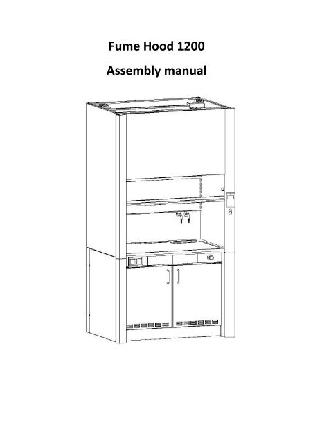
Fume Hood 1200Assembly manual
Assembling the <strong>fume</strong> hood:1. Framea) Lower frameb) Upper framec) Whole frame2. Internal sheetsa) Side wallsb) Back wallsc) Ceiling wallsd) Channel walls3. Windowa) Installation of the window in the frameb) Installation of the latchc) Screwing the slideslip with the window4. External sheetsa) Lower side platesb) Upper side platesc) Panel mountd) Front maske) Side plates5. Installationsa) Ventilation (duct and pipe to <strong>cupboard</strong>)b) Gasc) Hydraulicd) Electrical6. Cupboarda) Internal wallsb) Doorc) Shelfd) Installing the <strong>cupboard</strong> in the <strong>fume</strong> hood
1.We start assembling the <strong>fume</strong> hood with the assembling of the bottom sideframe. We screw the elements shown below using the M4 screws (DIN 7985).Additionally, we install two M10 rivets in the lower horizontal beam POL-6960.Perform the above steps for the left side too.
2.Using the 4.3mm DIN STR/Z rivets, install the POL-6968 and POL-7090strengthenings in the bottom side frame, then install the POL-6970strengthening in the way shown in the picture below.Perform the above steps for the left side too.
3.Turn the bottom side frame over. Using the rivets, install the POL-6968strengthening, then using the M4 (DIN 7985) screws, screw the POL-6969mount <strong>cupboard</strong> and the POL-7400 base <strong>cupboard</strong>.Perform the above steps for the left side too.
4.Connect the assembled side frames using the POL-6971, POL-6972 and POL-6979 horizontal beams and the M4 (DIN 7985) screws in the way shown in thepicture below.
5.Screw the POL-6977 strengthenings to the bottom frame, omitting 3 holeslocated highest. After that, screw the 4 POL-6970 strengthenings using the M4(DIN 7985) screws. At the end, screw the 4 POL-6973, POL-6974, POL-6975,POL-6976 vertical beams.
6.Start assembling the top frame with screwing the left POL-6981 and right POL-6980 Z-profiles to the vertical beams. Then, screw the POL-6982 horizontalbeam and the POL-6986 strengthening beam.
7.Before screwing the POL-6983 rear horizontal beam, use the rivets to install thePOL-6984 circle beams. After that, install it to the frame. At the end, screw therope circles using the POLT-159 tubes.
8.Start the installation of the inner plates with screwing the POL-7003 and POL-7004 sheets. Then, screw the POL-7005 rear sheet. At the end, screw the POL-7006 ceiling sheet.
9.According to the picture, screw the duct plates: POL-7008 bottom one, andPOL-7009 upper duct plate. Place the POL-7247 explosive security flap andscrew on both sides the POLT-230 window locks.
10.Place the window in the frame and screw it using the closing profiles (left POL-7869, right POL-7868 and bottom POL-7879).
11.Screw the sliders, the POL-7018 and POL-7019 plate lock and fenders.Backtrack the tongues of the sliders maximally to the rear to make themhidden.Screw the POL-7023 grip handle from the bottom of the window.
12.String the POLT-188 latch bar on the POL-7038 lower conducting. Screw thelower conducting to the POL-7023 grip handle. Place the spring on the bar andthe POLT-187 security pin.13.Use the POL-7037 upper guard to encase the latch mechanism. Screw thefenders too.
14.Screw the screws to the frame leaving 5mm space. Hang the POL-7872 grip ofsideslip 2 (right) and the POL-7870 grip of sideslip on the screws. After that,screw the screws to the end and thrust the sideslip.
15.Install the long steel rope (blue in the picture) to the POL-7018 plate lock, andthe short steel rope (green in the picture) to the POL-7019 plate lock.
16.Install the window by placing it between the slides and slide out the tongues tothe slides.
17.Stretch the steel ropes around the circle ropes according to the picture. Installthe endings of ropes to the POL-6987 weight plates using the shackles. Screwthe weight plate to the heaviness using the M8 screws.
Screw on the ventilation connection flange to the top of the <strong>fume</strong> <strong>cupboard</strong>,using M4x20 screws from the bottom and M4 nuts from top.Drilling holes in the base of the flange may be necessary.There are two connection pipes coming from the side of the flange – thesmaller one is used to connect the pressure sensor hose, and the Ø50 mm oneis used to connect the Underbench <strong>cupboard</strong> ventilation to the exhaust, usingtwo elastic pipes and one, vertical Ø50 mm pipe, mounted to the back wall ofthe <strong>fume</strong> hood through attached holders.Kołnierz wentylacjiVentillation connection flangePodłączenie wentylacji szafkiCupboard ventillation connectionPodłączenie czujnika przepływuAirflow sensor connection
POL-9760 Uchwyt krańcówkiPOL-9760 Microswitch holderKrańcówkaMicroswitchInstall the POL-9760 window position switch holder and then the greenmicroswitch, as seen on the picture, using M3 screws and nuts. Make sure thewindow moves the switch lever when lifted. Connect it using the “normallyopen” connections.
18.Screw the POL-7007 lower handle lighting from the inside to the inner walls ofthe <strong>fume</strong> hood. Screw the handle to the POL-7097 glass mount. Screw the POL-7091 sink mount to the upper horizontal beam.
19.Start the installation of the outer sheets with screwing the POL-6991 and POL-6992 lower outer sheets and the POL-6989 and POL-6990 upper outer sheets.After that, screw the POL-7096 (left) and POL-7095 (right) panel mounts, andthe POL-6998 and POL-6997 bottom brackets. Place the glass of lamp in theway shown in the picture (the glass is not screwed).
20.Using the POL-7093 and POL-7094 mount brackets, screw the POL-7092 rearlower side plates.Install a small electrical box on the right-rear support of the <strong>fume</strong> hood, usingmetal-screws – this will be used to connect the input power cable, and let outthe cables leading to the control box and the sockets located on front panels.Use another metal-screw to connect the grounding cable to <strong>fume</strong> hoodstructure.
21.After pushing the worktop in from the front, glue the ceramic sink in placeunder the worktop, using silicone. Put the drain and siphon on the sink.Uchwyt zlewikaSink holderZlewikSinkOdpływDrainSyfonSiphon
Next, install the shared connections panel (the number of services will differaccording to <strong>fume</strong> hood configuration). Connect the taps and sockets to theappropriate installations. Screw the POL-6996 front mask and place the POL-7223, POL-7224, POL-7221, POL-7222 masks.Install the water and gas outlets in the work chamber’s back wall holes.
22.Assemble the door. Tuck the POL-7034 sheet in the POL-7032 sheet and screwthem from the bottom. Then, screw the handle. Screw the hinge part 1 to theinner sheet. Assemble the left door in the same way.
23.The chamber consists of 5 sheets. Use the rivets to connect the POL-7027 rightwall with the 7026 upper sheet and the POL-7029 bottom wall. Place the POL-7028 left wall and the POL-7030 rear wall too.
24.Screw the second part of hinges and the POL-7797 plugs. Place the POL-09-4017-06 shelf bracket on the shelf boards and put the POL-7036 shelf.Zakręcamy drugą część zawiasów i zaślepki okna rewizyjnego.Następnie na każdą listwę półki zakładamy Uchwyt półki POL-09-4017-06 iwsuwamy Półkę POL-7036.
In the round hole of the back wall install the plastic grid with Ø50 mmconnection. Use this to connect the <strong>cupboard</strong> to the exhaust system.Kratka wentylacyjna z króćcem Ø50 mmPlastic grid with Ø50 mm connectionScrew on the door.
25.Insert the <strong>cupboard</strong> into the <strong>fume</strong> hood and screw it using 4 M4 screws fromthe inner side of the <strong>cupboard</strong> to the <strong>fume</strong> hood. At the end, screw the POL-6999 lower guard.
26.Connect the <strong>fume</strong> hood control box according to the below scheme and put iton top of the <strong>fume</strong> hood. Connect the RJ-45 cable to the controller and controlpanel, screw the control panel on its place in the right side-panel of the <strong>fume</strong>hood.
28.When everything else has been done, seal the gap around the worktop withthe Unipox Fugen-Epoxi putty.If the <strong>fume</strong> <strong>cupboard</strong> is equipped with ceramic work chamber lining, fill thejoints between its elements with this putty as well.If the <strong>fume</strong> <strong>cupboard</strong> is equipped with phenolic resin work chamber lining, fillthe joints between its elements with silicone.