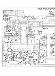
SLV-SE85/SF90/SF99
SLV-SE85/SF90/SF99
SLV-SE85/SF90/SF99

Create successful ePaper yourself
Turn your PDF publications into a flip-book with our unique Google optimized e-Paper software.
2-3. SYSTEM CONTROL SYSTEM ADJUSTMENT2-3-1. Clock Adjustment (FR-161 board)[Adjustment Purpose]To adjust the precision of the clock. If this specification is notsatisfied, the clock will lose or will gain time.ModeE-ESignalArbitraryMeasurement Point IC180 Pin ^ (BUZZER)Measuring InstrumentAdjusting elementSpecified ValueFrequency counterCT180f = 8.192000 to 8.1920325kHz[Adjusting method]1) Connect JL237 (Connecting point of R416 (2.2kΩ) and R412(2.2kΩ)) and GND with a jumper wire.2) Adjust the BUZZER frequency (f) to the specified value withCT180.3) Remove the jumper wire.2-4. SERVO SYSTEM ADJUSTMENT2-4-1. RF Switching Position Adjustment(MA-359 board)[Adjustment Purpose]To adjust the link of the A-ch and B-ch of the tape playback outputs.To make the unit compatible with other tapes and units. If thisspecification is not satisfied, the link will appear on the screen andthe screen will be disrupted, etc.ModePlaybackSignalAlignment tape: SP mode color barportion[Adjustment method]1) Connect RP-235 board CN261 pin 5 (AV ADJ) and GNDwith a jumper wire.2) Check that “AP” indicator on the display window turns on.3) Remove the jumper wire.4) Press EJECT button. (RF switching position adjustment isperformed automatically. )5) Perform “Hi-Fi Switching Position Adjustment”.2-4-2. Hi-Fi Switching Position Adjustment(MA-359 board)[Adjustment Purpose]To adjust the link of the A-ch and B-ch of the tape playback outputs.To make the unit compatible with other tapes and units. If thisspecification is not satisfied, the switching noise will be heard, etc.ModePlaybackSignalAlignment tape: SP mode color barportionMeasurement Point CH1: RP-235 board CN341 pin 1(HF ADJ)CH2: RP-235 board CN261 pin 2(RF SWP)Measuring Instrument OscilloscopeSpecified Value A = minimumNote: Perform “RF Switching Position Adjustment” before this adjustment.[Adjustment method]1) Connect RP-235 board CN261 pin 5 (AV ADJ) and GNDwith a jumper wire.2) Check that “AP” indicator on the display window turns on.3) Remove the jumper wire.4) Press REC button.5) Check that “AH” indicator on the display window turns on.6) Press PROGRAM+ and PROGRAM– buttons and minimizethe part A of PB AF RF signal.7) Press PAUSE button.8) Check that the “AH” indicator turns off.ACH1CH22 VFig. 6-2-3.6-3