10 AND 12-BIT GRAYSCALE TECHNOLOGY - Nvidia
10 AND 12-BIT GRAYSCALE TECHNOLOGY - Nvidia
10 AND 12-BIT GRAYSCALE TECHNOLOGY - Nvidia

Create successful ePaper yourself
Turn your PDF publications into a flip-book with our unique Google optimized e-Paper software.
<strong>10</strong> <strong>AND</strong> <strong>12</strong>-<strong>BIT</strong> <strong>GRAYSCALE</strong><strong>TECHNOLOGY</strong>TB-04631-001_v04 | April 2013Technical Brief
DOCUMENT CHANGE HISTORYTB-04631-001_v04Version Date Authors Description of Change01 April 17, 2009 SV, SM Initial Release02 February 9, 20<strong>10</strong> SV, SM Addition of Table 203 February 7, 2011 SV, SM • Updated “System Specification” section• Updated “Supported Connectors” section• Updated Table 3 and Table 4• Removed “Moving and Spanning WindowsAcross Displays” section• Removed “Targeting Specific GPUs forRendering” section• Added “Directed GPU Rendering” section• Updated “Implementation Details” section04 April 5, 2013 AS, SV, SM • Updated to include current NVIDIA ® Kepler products• Updated to include support for OpenGL <strong>10</strong>-bit per component pixel formats<strong>10</strong> and <strong>12</strong>-Bit Grayscale Technology TB-04631-001_v04 | ii
TABLE OF CONTENTSIntroduction ....................................................................................... 1System Specification ........................................................................... 3Supported Graphics Boards .................................................................... 4Supported Monitors ............................................................................. 5Typical Multi-Display Configuration .......................................................... 6Case 1. Two 5 MP Grayscale Displays Driven by One Quadro Card .................... 6Case 2. Four 5 MP Grayscale Displays Driven by Two Quadro Cards .................. 8Supported Connectors .......................................................................... 9Single or Dual-Link DVI ...................................................................... 9DisplayPort and Adapters ................................................................... 9Grayscale Monitor Settings ................................................................... <strong>12</strong>Grayscale Application Development ......................................................... 13DVI Driver Layer ................................................................................ 13Older Method for DVI Application Level Pixel Packing .................................... 14OpenGL <strong>10</strong>-Bit Pixel Format for DVI and DisplayPort on Windows 7 .................... 17Creating a <strong>10</strong> bpc OpenGL Window ....................................................... 17Multi-Display Configurations with Kepler ................................................... 19Multiple Display Setup ......................................................................... 19Mixing Grayscale and Color Displays ........................................................ 22Appendix .......................................................................................... 24Multi-GPU Compatibility for Pre-Kepler Cards ............................................. 24Directed GPU Rendering ...................................................................... 25References ...................................................................................... 27Implementation Details ....................................................................... 27<strong>10</strong> and <strong>12</strong>-Bit Grayscale Technology TB-04631-001_v04 | iii
LIST OF FIGURESFigure 1. <strong>10</strong> MPixel <strong>10</strong>-Bit Diagnostic Mammography Display .............................. 2Figure 2. Application Enhanced Using Multiply Displays .................................... 3Figure 3. <strong>10</strong> MP Grayscale Configuration ..................................................... 6Figure 4. Three GPUs Driving a 20 MP Grayscale Display ................................... 8Figure 5. DisplayPort to Single-Link DVI Adapter (Passive) ............................... <strong>10</strong>Figure 6. Latched Mini-DisplayPort ........................................................... <strong>10</strong>Figure 7. Latched Mini-DisplayPort to Single-Link DVI ..................................... 11Figure 8. DisplayPort to Dual-Link DVI Adapter (Active) .................................. 11Figure 9. Enable 5 MP Grayscale Monitor to Display Higher Resolution ................. <strong>12</strong>Figure <strong>10</strong>. Driver Converts and Packs Desktop from 24-Bit Color to <strong>12</strong>-Bit Gray ........ 14Figure 11. Application Level Texture Setup for <strong>10</strong> and <strong>12</strong>-Bit Grayscale Display ....... 16Figure <strong>12</strong>. Display Properties Before and After Displays are Enabled .................... 20Figure 13. Setting Render GPU from NVIDIA Control Panel................................. 26LIST OF TABLESTable 1. Grayscale Implementation Method Based On Display Connector and OS ..... 3Table 2. Quadro Graphics Boards with <strong>10</strong> and <strong>12</strong>-Bit Grayscale Support ............... 4Table 3. Grayscale Capable Display Panels with Supported Resolution and PixelDepth ................................................................................... 5Table 4. Single Card Option for Dual Display Configurations ............................. 7Table 5. 20 MP Configuration .................................................................. 9Table 6. Multi-GPU Compatibility ............................................................ 25<strong>10</strong> and <strong>12</strong>-Bit Grayscale Technology TB-04631-001_v04 | iv
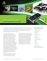
INTRODUCTIONAdvances in sensor technology and image acquisition techniques in the field ofradiology are producing high bit depth grayscale images in the range of <strong>12</strong> to 16-bit perpixel. At the same time, the adoption of displays with native support for <strong>10</strong> and <strong>12</strong>-bitgrayscale is growing. These affordable displays are DICOM[1] conformant to preserveimage quality and consistency. Furthermore, expanded display capabilities of the latestNVIDIA Quadro ® cards enable tiling together multiple high resolution displays for sideby-sidecomparisons from a single card.Standard graphics workstations however are limited to 8-bit grayscale, which providesonly 256 possible shades of gray for each pixel sometimes obscuring subtle contrasts inhigh density images. Radiologists often use window-leveling techniques to identify theregion of interest that can quickly become a cumbersome and time-consuming userinteraction process.NVIDIA’s <strong>10</strong>–bit and <strong>12</strong>-bit grayscale technology allows these high quality displays tobe driven by standard NVIDIA ® Quadro ® graphics boards preserving the full grayscalerange. This is done in 2 modes. “Pixel Packing” where the <strong>10</strong>-bit or <strong>12</strong>-bit grayscale data is transmitted from theQuadro graphics board to a high grayscale density display using a standard DVIcable. Instead of the standard three 8-bit color components per pixel, the pixelpacking allows two <strong>10</strong> or <strong>12</strong>-bit pixels to be transmitted, providing higher spatialresolution and grayscale pixel depth as compared to an 8-bit system. In recent driers,this pixel packing is done by driver transparent to the application when <strong>10</strong>-bit percomponent pixel formats are used. This greatly simplifies programming in additionto making the application portable across multiple vendor hardware. Using <strong>10</strong>-bit pixel formats over a VESA ® DisplayPort output connection. No pixelpacking is required as DisplayPort has sufficient bandwidth to transfer 5 MPixelswith full <strong>10</strong>-bit RGB color channels.<strong>10</strong> and <strong>12</strong>-Bit Grayscale Technology TB-04631-001_v04 | 1
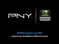
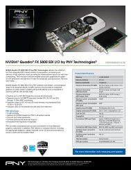
IntroductionAs specialty hardware is not required, NVIDIA’s <strong>10</strong>-bit grayscale technology is readilyavailable for use with other radiology functions and easy to support amongst a widerange of grayscale panels from various manufacturers. In a preliminary studyperformed on <strong>10</strong> radiologists using Dome E5 <strong>10</strong>-bit vs. E5 8-bit displays in conjunctionwith Three Palms <strong>10</strong>-bit, OpenGL accelerated Workstation One mammographyapplication, radiologists’ performance was statistically significant on the <strong>10</strong>-bit enableddisplay systems, some experiencing triple the read time speedup.This technical brief describes the NVIDIA grayscale technology, the systemrequirements and setup. It also aims to guide users through common pitfalls that arisewhen extending to multi-display and multi graphics processing unit (GPU)environments routinely used in diagnostic imaging and recommends best practices.Figure 1 shows the latest technology in digital diagnostic display systems, a Quadrocard driving a <strong>10</strong> mega-pixel, <strong>10</strong>-bit grayscale display. Figure 2 shows a <strong>10</strong>-bit enabledmammography application displaying multiple modalities on multiple displays.Figure 1. <strong>10</strong> MPixel <strong>10</strong>-Bit Diagnostic Mammography Display 11Image courtesy of NDS Surgical Imaging, DOME Z<strong>10</strong><strong>10</strong> and <strong>12</strong>-Bit Grayscale Technology TB-04631-001_v04 | 2
IntroductionFigure 2. Application Enhanced Using Multiply Displays 2SYSTEM SPECIFICATION <strong>10</strong> and <strong>12</strong>-bit grayscale is currently supported on● Windows XP 32-bit and 64-bit● Windows 7 and Windows 8 (Aero should be enabled for best performance) Grayscale with <strong>10</strong>-bit pixel formats is only supported for OpenGL based applicationsTable 1 summarizes the guidelines for specific implementation methods based on thedisplay connector and operating system.Table 1.Grayscale Implementation Method Based On DisplayConnector and OSOperating System DVI DisplayPortWindows 7 OpenGL <strong>10</strong> bpc pixel format OpenGL <strong>10</strong> bpc pixel formatWindows XP Application pixel packaging OpenGL <strong>10</strong> bpc pixel format2Image courtesy of Threepalms, Inc.<strong>10</strong> and <strong>12</strong>-Bit Grayscale Technology TB-04631-001_v04 | 3
IntroductionSUPPORTED GRAPHICS BOARDSThe boards shown in Table 2 support <strong>10</strong>-bit grayscale and are NVIDIA ® CUDA ®enabled.Table 2.Quadro Graphics Boards with <strong>10</strong> and <strong>12</strong>-Bit Grayscale SupportMid range – Quadro K2000D, Quadro K2000, Quadro 2000D, Quadro600, Quadro 2000Recommended for 2D image displayand manipulation use cases overmultiple displays. No auxiliarypower is required.High end – Quadro K4000, Quadro 4000Recommended if the primary usageis to display and compute with 2Dgrayscale and 3D data.Ultra high end – Quadro K5000, Quadro 6000, Quadro 5000Recommended for applications thatalso require rendering andprocessing large 3D and 4Dgeometries and volumes.Quadro Plex 7000,Quadro Plex 2200 D2Dedicated deskside visualcomputing system composed of 2highest-end Quadro graphics boardswith up to <strong>12</strong> GB of total graphicsmemory. Recommended foradvanced visualization and largescale projection and display usecases.<strong>10</strong> and <strong>12</strong>-Bit Grayscale Technology TB-04631-001_v04 | 4
IntroductionSUPPORTED MONITORSTable 3.Grayscale Capable Display Panels with Supported Resolutionand Pixel DepthManufacturer Panel Supported ResolutionsDome E2• 1600 × <strong>12</strong>00 at 60 Hz• <strong>12</strong>00 × 1600 at 60 HzDome E3• 2048 × 1536 at 60 Hz• 1536 × 2048 at 60 HzNDS SurgicalImagingEizoNECWideBeaconDome S3,Dome S3cDome E5Dome Z<strong>10</strong>GS 520GS 521GX 530GX <strong>10</strong>30MD215MGMD205MG,MD205MG-1MD211G3MD213MGMD21GS-3MPMD21GS-2MPIF2<strong>10</strong>5PMG32SPG51SP• 2048 × 1536 at 60 Hz• 1536 × 2048 at 60 Hz• 2560 × 2048 at 50 Hz• 2048 × 2560 at 50 Hz• 4096 × 2560 at 50 Hz• 2560 × 4096 at 50 Hz• 2560 × 2048 at 50 Hz• 2048 × 2560 at 50 Hz• 2560 × 2048 at 50 Hz• 2048 × 2560 at 50 Hz• 2560 × 2048 at 50 Hz• 2048 × 2560 at 50 Hz• 2560 × 4096 at 50 Hz• 4096 × 2560 at 50 Hz• 2560 × 2048 at 57 Hz• 2048 × 2560 at 57 Hz• 2560 × 2048 at 57 Hz• 2048 × 2560 at 57 Hz• 2560 × 2048 at 57 Hz• 2048 × 2560 at 57 Hz• 2048 × 1536 at 60 Hz• 1536 × 2048 at 60 Hz• 2048 × 1536 at 60 Hz• 1536 × 2048 at 60 Hz• 1600 × <strong>12</strong>00 at 60 Hz• <strong>12</strong>00 × 1600 at 60 Hz• 2560 × 2048 at 50 Hz• 2048 × 2560 at 50 Hz• 2048 × 1536 at 60 Hz• 1536 × 2048 at 60 Hz• 2560 × 2048 at 57 Hz• 2048 × 2560 at 57 HzGrayscaleDepth<strong>10</strong> and <strong>12</strong>-bit<strong>10</strong> and <strong>12</strong>-bit<strong>10</strong> and <strong>12</strong>-bit<strong>10</strong> and <strong>12</strong>-bit<strong>10</strong> and <strong>12</strong>-bit<strong>10</strong>-bit<strong>10</strong>-bit<strong>10</strong>-bit<strong>10</strong>-bit<strong>10</strong>-bit<strong>10</strong>-bit<strong>10</strong>-bit<strong>10</strong>-bit<strong>10</strong>-bit<strong>10</strong>-bit<strong>10</strong>-bit<strong>10</strong>-bit<strong>10</strong>-bitPackedPixel DVIYesYesYesYesYesYesYesNoYesYesYesYesYesYesYesYesYesYes<strong>10</strong>-BitDisplayPortNoNoNoNoYesYesNoYesNoNoNoNoNoNoNoNoNoNo<strong>10</strong> and <strong>12</strong>-Bit Grayscale Technology TB-04631-001_v04 | 5
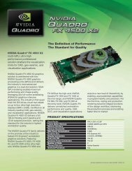
IntroductionTYPICAL MULTI-DISPLAY CONFIGURATIONWe examine the commonly used multi-display setups that mix grayscale monitors andcolor panels and their underlying GPU configuration.Case 1. Two 5 MP Grayscale Displays Driven by OneQuadro CardThe most commonly used configuration for diagnostic imaging, a single Quadro K4000,Quadro K2000, or Quadro K2000D drives two 5 MP grayscale displays plus a side“worklist” display.Figure 3.<strong>10</strong> MP Grayscale Configuration<strong>10</strong> and <strong>12</strong>-Bit Grayscale Technology TB-04631-001_v04 | 6
IntroductionTable 4 shows the two single card configuration options for a <strong>10</strong> MP setup. The customercan choose between the options for either the Quadro K2000 and Quadro K4000 or theQuadro K2000D.Table 4.Single Card Option for Dual Display ConfigurationsDisplaysSide DisplayQuadro K2000 or Quadro K4000(If Diagnostic Display SupportsDisplayPort)DVIconnectorDisplayPortconnectorDisplayPortconnectorQuadro K2000D(If Diagnostic Display Only Supports DVI)DVI orDisplayPort(through mini-DisplayPortadapter)Dual-linkDVIconnectorDual-linkDVIconnector2-5 MP DiagnosticDisplay2-5 MP DiagnosticDisplay<strong>10</strong> and <strong>12</strong>-Bit Grayscale Technology TB-04631-001_v04 | 7
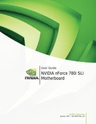
IntroductionCase 2. Four 5 MP Grayscale Displays Driven by TwoQuadro CardsIn this configuration, a single Quadro K4000, Quadro K2000, or Quadro K2000D candrive two 5 MP grayscale displays plus a side "worklist" display. A second QuadroK4000, Quadro K2000, or Quadro K2000D card can drive the remaining two 5 MPdisplays.Figure 4.Three GPUs Driving a 20 MP Grayscale Display<strong>10</strong> and <strong>12</strong>-Bit Grayscale Technology TB-04631-001_v04 | 8
IntroductionTable 5 shows the two graphics cards required configuration for a 20 MP setup. Theconfiguration requires two Quadro K2000, Quadro K2000D, or Quadro K4000 cards.Table 5.20 MP ConfigurationDisplaysSide DisplayQuadro K2000, Quadro K2000D, orQuadro K4000DVIconnectorDisplayPortor DVIconnectorDisplayPortor DVIconnectorQuadro K2000, Quadro K2000D, orQuadro K4000DVI connectorDisplayPortor DVIconnectorDisplayPortor DVIconnector2-5 MP DiagnosticDisplay2-5 MP DiagnosticDisplay2-5 MP DiagnosticDisplay2-5 MP DiagnosticDisplaySUPPORTED CONNECTORSSingle or Dual-Link DVIAlthough single-link DVI is only capable of transmitting up to HD (1920 × <strong>12</strong>00), ourgrayscale pixel packing mechanism allows 5 MP (2560 × 2048) images to be sent oversingle-link DVI.DisplayPort and Adapters As displays are increasingly adopting DisplayPort, the native DisplayPortconnectors on Quadro cards can be connected directly via DisplayPort cables. For standard size DisplayPort connectors to single-link DVI conversion, passiveadapters such as Hosiden (P/N TYX1602-0<strong>10</strong>307) and Simula (P/N DJ8028B-<strong>10</strong>00-<strong>10</strong>E) are tested and recommended. On the Quadro K2000D for latched mini-DisplayPort to standard size DisplayPortconversion, use Bizlink P/N KS30011-B07 or Simula P/N CB802E-4000-<strong>10</strong>H. On the Quadro K2000D for latched mini-DisplayPort to single-link DVI conversion,use Bizlink PN KS30037-C07.<strong>10</strong> and <strong>12</strong>-Bit Grayscale Technology TB-04631-001_v04 | 9
Introduction To support dual-link resolutions from a DisplayPort connector, an active adapter isrequired. As shown in Figure 8 this dongle includes a built in USB cable connectingto the USB port providing power to the adapter. NVIDIA recommends the BizlinkDisplayPort-to-DVI-D dual-link cable adapter (P/N KS<strong>10</strong>014-207). The Simula and Bizlink adapters can be purchased from NVIDIA’s online store athttp://store.nvidia.com/ (under the cables category).Figure 5.DisplayPort to Single-Link DVI Adapter (Passive)Figure 6.Latched Mini-DisplayPort<strong>10</strong> and <strong>12</strong>-Bit Grayscale Technology TB-04631-001_v04 | <strong>10</strong>
IntroductionFigure 7.Latched Mini-DisplayPort to Single-Link DVIFigure 8.DisplayPort to Dual-Link DVI Adapter (Active)<strong>10</strong> and <strong>12</strong>-Bit Grayscale Technology TB-04631-001_v04 | 11
Introduction<strong>GRAYSCALE</strong> MONITOR SETTINGSWhen a grayscale compatible monitor is connected to a suitable NVIDIA Quadrosolution, the NVIDIA driver automatically detects it and immediately switches topacked pixel mode. Therefore, there are no control panel settings to enable and disable<strong>10</strong>-bit grayscale. On Windows XP, the only setting required is to enable the grayscalemonitor to display at its optimal resolution as shown in the following steps for a 5 MPpanel with resolution 2560 × 2048. Note: These steps are not required on Windows 7 and Windows 8.1. Open the Display Properties.2. Select the Settings tab.3. Click on Advanced.4. Select the Monitor tab.5. Uncheck the Hide modes that this monitor cannot display check box.6. Click Apply. The maximum resolution is now set to 2560 × 2048.Figure 9.Enable 5 MP Grayscale Monitor to Display Higher Resolution<strong>10</strong> and <strong>12</strong>-Bit Grayscale Technology TB-04631-001_v04 | <strong>12</strong>
<strong>GRAYSCALE</strong> APPLICATION DEVELOPMENTDVI DRIVER LAYEROn grayscale enabled Quadro solution, the driver implements a pixel packingmechanism that is transparent to the desktop and to the application. The 24-bit RGBdesktop is first converted to <strong>12</strong>-bit grayscale using the NTSC color conversion formulaand then two <strong>12</strong>-bit gray values are packed into 1 RGB DVI pixel and finally shipped tothe monitor. This pixel packing allows displaying of 5 MP gray values just using asingle-link DVI (that is normally limited to HD resolution).<strong>10</strong> and <strong>12</strong>-Bit Grayscale Technology TB-04631-001_v04 | 13
Grayscale Application DevelopmentFigure <strong>10</strong>. Driver Converts and Packs Desktop from 24-Bit Color to <strong>12</strong>-Bit GrayOLDER METHOD FOR DVI APPLICATION LEVEL PIXELPACKINGThis is a legacy method mostly used for applications on Windows XP using DVIdisplays, but will work with Windows 7 and Windows 8 if the same code base is to beshared.The <strong>10</strong> and <strong>12</strong>-bit grayscale image viewing application is responsible for outputing 24-bit RGB pixels which the driver then converts to <strong>12</strong>-bit grayscale values for scanout asdescribed in the previous section.The application uses a shader that takes in the <strong>12</strong>-bit grayscale value from the image andtranslates it into a 24-bit RGB pixel using a lookup table. The lookup table is generatedto find the best RGB pixel with as little as possible differences between the RGB values(preferred is R=G=B) for each grayscale value in the input image. In essence, this process<strong>10</strong> and <strong>12</strong>-Bit Grayscale Technology TB-04631-001_v04 | 14
Grayscale Application Developmentis the inverse of the driver conversion from RGB to grayscale. The end result is that thegrayscale image on the desktop looks like a grayscale image on a color monitor.The integer texture extension, EXT_texture_integer [4] in Shader Model 4 is used tostore the incoming grayscale image as a 16-bit unsigned integer without converting tofloating point representation saving memory footprint by 2×.glPixelStorei(GL_UNPACK_ALIGNMENT, 2);glTexImage2D(GL_TEXTURE_2D, 0, GL_ALPHA16UI_EXT, width, height, 0, GL_ALPHA_INTEGER_EXT ,GL_UNSIGNED_SHORT, TextureStorage);The lookup table mapping the grayscale image to 24-bit RGB values is stored as 1Dtexture. The lookup table dimensions should exactly match the bit depth of the grayscalevalues expected in incoming image so that no filtering and interpolation operations willbe performed thus preserving image precision and fidelity. Changes to contrast,brightness and window level of the image are easily done by changing the lookup tableresulting in a 1D texture download without any change to the source image.#extension GL_EXT_gpu_shader4 : enable // for unsigned int support uniform usampler2DtexUnit0; // Gray Image is in tex unit 0uniform sampler1D texUnit1; // Lookup Table Texture in tex unit 1void main(void){vec2 TexCoord = vec2(gl_TexCoord[0]);//texture fetch of unsigned ints placed in alpha channeluvec4 GrayIndex = uvec4(texture2D(texUnit0, TexCoord));//low <strong>12</strong> bits taken onlyfloat GrayFloat = float(float(GrayIndex.a) / 4096.0);//fetch right grayscale value out of tablevec4 Gray = vec4(texture1D(texUnit1, GrayFloat));// write data to the framebuffergl_FragColor = Gray.rgba;}<strong>10</strong> and <strong>12</strong>-Bit Grayscale Technology TB-04631-001_v04 | 15
Grayscale Application DevelopmentFigure 11. Application Level Texture Setup for <strong>10</strong> and <strong>12</strong>-Bit GrayscaleDisplay<strong>10</strong> and <strong>12</strong>-Bit Grayscale Technology TB-04631-001_v04 | 16
Grayscale Application DevelopmentOPENGL <strong>10</strong>-<strong>BIT</strong> PIXEL FORMAT FOR DVI <strong>AND</strong>DISPLAYPORT ON WINDOWS 7A significant drawback of the pixel packing mechanism explained in the previoussection is that it requires more programming work by the application developer and isvendor dependent. With the latest drivers, the implementation is significantly madeeasier with the use of OpenGL native <strong>10</strong>-bit pixel format. This is the recommended pathfor the following: Windows 7 based applications – supported for monitors requiring DVI pixel packingand ones that support grayscale over DisplayPort. Windows XP – only enabled on panels with DisplayPort support.In this case, the application doesn’t need to manage the lookup into the grayscale tablein the shader as this is done seamlessly under the hood by the driver (for DVI). Theapplication is responsible for creating the input texture using the integer textureextension as explained in the previous section and the driver does the necessaryconversions to make the data visible on screen.Creating a <strong>10</strong> bpc OpenGL WindowOn Windows, the displayable 30-bit pixel formats are exported viaWGL_ARB_pixelformat extension [5]. To access these pixel formats, the WGL pixelformat functions are used instead of their GDI equivalents. A dummy OpenGL windowmust be created in order to get a handle to these WGL functions.// Create a dummy window to query the WGL_ARB_pixelformatsHWND dummyWin = CreateDummyGLWindow(szClassName, "Dummy", FALSE);if (dummyWin == NULL) {// TODO - Error Handling here}HDC dummyDC = GetDC(dummyWin);// TODO – Set Pixel FormatHGLRC dummyRC = (HGLRC) wglCreateContext (dummyDC);// Set the OpenGL context currentwglMakeCurrent(dummyDC, dummyRC);// Find the 30-bit color ARB pixelformatwglGetExtensionsString = (PFNWGLGETEXTENSIONSSTRINGARBPROC)wglGetProcAddress("wglGetExtensionsStringARB");if (wglGetExtensionsString == NULL) {// TODO - Error Handling and Cleanup here}const char *szWglExtensions = wglGetExtensionsString(dummyDC);if (strstr(szWglExtensions, " WGL_ARB_pixel_format ") == NULL) {// TODO - Error Handling and Cleanup here}wglGetPixelFormatAttribiv = (PFNWGLGETPIXELFORMATATTRIBIVARBPROC)wglGetProcAddress("wglGetPixelFormatAttribivARB");wglGetPixelFormatAttribfv = (PFNWGLGETPIXELFORMATATTRIBFVARBPROC)wglGetProcAddress("wglGetPixelFormatAttribfvARB");<strong>10</strong> and <strong>12</strong>-Bit Grayscale Technology TB-04631-001_v04 | 17
Grayscale Application DevelopmentwglChoosePixelFormat = (PFNWGLCHOOSEPIXELFORMATARBPROC)wglGetProcAddress("wglChoosePixelFormatARB");if ((wglGetPixelFormatAttribfv == NULL) || (wglGetPixelFormatAttribiv == NULL) ||(wglChoosePixelFormat == NULL))// TODO - Error Handling and Cleanup hereThe <strong>10</strong> bits per component is specified in the desired attribute list before calling thewglChoosePixelFormat which returns the matching pixel formats. The following codelisting also checks the RGB color depth after the call to make sure that a 30-bit color pixelformat is in place.int attribsDesired[] = {WGL_DRAW_TO_WINDOW_ARB, 1,WGL_ACCELERATION_ARB, WGL_FULL_ACCELERATION_ARB,WGL_RED_<strong>BIT</strong>S_ARB, <strong>10</strong>,WGL_GREEN_<strong>BIT</strong>S_ARB, <strong>10</strong>,WGL_BLUE_<strong>BIT</strong>S_ARB, <strong>10</strong>,WGL_ALPHA_<strong>BIT</strong>S_ARB, 2,WGL_DOUBLE_BUFFER_ARB, 1,0,0};UINT nMatchingFormats;int index = 0;if (!wglChoosePixelFormat(dummyDC, attribsDesired, NULL, 1, &index, &nMatchingFormats)) {printf("ERROR: wglChoosePixelFormat failed!\n");goto cleanup;}if (nMatchingFormats == 0) {printf("ERROR: No <strong>10</strong>bpc WGL_ARB_pixel_formats found!\n");goto cleanup;}// Double-check that the format is really <strong>10</strong>bpcint redBits;int alphaBits;int uWglPfmtAttributeName = WGL_RED_<strong>BIT</strong>S_ARB;wglGetPixelFormatAttribiv(dummyDC, index, 0, 1, &uWglPfmtAttributeName, &redBits);uWglPfmtAttributeName = WGL_ALPHA_<strong>BIT</strong>S_ARB;wglGetPixelFormatAttribiv(dummyDC, index, 0, 1, &uWglPfmtAttributeName, &alphaBits);printf("pixelformat chosen, index %d red bits: %d alpha bits: %d", index, redBits,alphaBits);<strong>10</strong> and <strong>12</strong>-Bit Grayscale Technology TB-04631-001_v04 | 18
MULTI-DISPLAY CONFIGURATIONS WITHKEPLERDiagnostic imaging commonly requires multiple displays for side by side modalitycomparisons. Multi-display configurations are becoming easier to manage with newQuadro boards like the Quadro K5000, Quadro K4000, and Quadro K2000 - which candrive up to 4 simultaneous displays. Depending on the available PCI slots within asystem, multiple cards can be used to drive more than 4 displays. These multipledisplays can be a mix of regular color LCD panels and specialty grayscale monitors. Thissection explains the issues that arise from such a heterogeneous configuration andprogramming pointers to address them. The full source code for the examples is foundin the accompanying Grayscale<strong>10</strong>-bit SDK.MULTIPLE DISPLAY SETUPFor Windows XP, the multi-display capability has to be enabled explicitly as follows. Toenable multi-display from the desktop follow these simple steps.1. Open the Display Properties.2. Select the Settings tab.3. Check the Extend my Windows desktop onto this monitor checkbox for each display asshown in Figure 8.<strong>10</strong> and <strong>12</strong>-Bit Grayscale Technology TB-04631-001_v04 | 19
Multi-Display Configurations with KeplerFigure <strong>12</strong>. Display Properties Before and After Displays are EnabledFor an application using multiple GPU’s and displays it is often useful toprogrammatically find out their attributes and capabilities. This section and thefollowing ones show code samples to demonstrate that in progressive detail. Followingare some data structures used throughout the document examples. The CDisplayWinstructure defined in CDisplayWin.[h|cpp]encapsulates the attributes of each displayand the displayWinList is a container for all displays. Accessing functions have beenomitted to aid readability.class CDisplayWin {HWND hWin; // handle to display windowHDCwinDC; // DC of display windowRECT rect; // rectangle limits of displaybool primary; //Is this the primary displaychar displayName[<strong>12</strong>8]; //name of this displaychar gpuName[<strong>12</strong>8]; //name of associated GPUbool grayScale; //Is this a grayscale displaypublic:bool spans(RECT r);//If incoming rect r spans this display}#define MAX_NUM_GPUS 4int displayCount = 0; //number of active displays<strong>10</strong> and <strong>12</strong>-Bit Grayscale Technology TB-04631-001_v04 | 20
Multi-Display Configurations with Kepler//list of displays, each gpu can attach to max 2 displaysCDisplayWin displayWinList[MAX_NUM_GPUS*2];Following is a simple example using the Windows GDI to enumerate the attacheddisplays, gets their extents and also check if the display is set as primary. The followingcode can be easily modified to include unattached displays.DISPLAY_DEVICE dispDevice;DWORD displayCount = 0;memset((void *)&dispDevice, 0, sizeof(DISPLAY_DEVICE));dispDevice.cb = sizeof(DISPLAY_DEVICE);// loop through the displays and print out statewhile (EnumDisplayDevices(NULL,displayCount,&dispDevice,0)) {if (dispDevice.StateFlags & DISPLAY_DEVICE_ATTACHED_TO_DESKTOP) {printf("DeviceName = %s\n", dispDevice.DeviceName);printf("DeviceString = %s\n",dispDevice.DeviceString);if (dispDevice.StateFlags &DISPLAY_DEVICE_PRIMARY_DEVICE)printf("\tPRIMARY DISPLAY\n");DEVMODE devMode;memset((void *)&devMode, 0, sizeof(devMode));devMode.dmSize = sizeof(devMode);EnumDisplaySettings(dispDevice.DeviceName, ENUM_CURRENT_SETTINGS,&devMode);printf("\tPosition/Size = (%d, %d), %dx%d\n", devMode.dmPosition.x,devMode.dmPosition.y,devMode.dmPelsWidth, devMode.dmPelsHeight);HWND hWin =createWindow(GetModuleHandle(NULL),devMode.dmPosition.x+50,devMode.dmPosition.y+50, devMode.dmPelsWidth-50, devMode.dmPelsHeight-50);if (hWin) { //got a windowHDC winDC = GetDC(hWin);// TODO - set pixel format, create OpenGL context}elseprintf("Error creating window \n");}//if attached to desktopdisplayCount++;} //while(enumdisplay);Running this enumeration code on our 3 display example (shown in Figure <strong>12</strong>), printsout the following:DeviceName = \\.\DISPLAY1DeviceString = NVIDIA Quadro K2000PRIMARY DISPLAYPosition/Size = (0, 0), <strong>12</strong>80x<strong>10</strong>24DeviceName = \\.\DISPLAY2DeviceString = NVIDIA Quadro K2000Position/Size = (<strong>12</strong>80, 0), 2560x2048DeviceName = \\.\DISPLAY3DeviceString = NVIDIA Quadro K2000Position/Size = (3840, 0), 1600x<strong>12</strong>00 Note: The enumeration shown in this section abstracts special hardwarecapabilities of the displays such as grayscale or color capability. For such physicaldisplay details, we need to access to the Extended display identification data(EDID) the data structure provided by the computer display to the graphics card.This is described in the next section.<strong>10</strong> and <strong>12</strong>-Bit Grayscale Technology TB-04631-001_v04 | 21
Multi-Display Configurations with KeplerMIXING <strong>GRAYSCALE</strong> <strong>AND</strong> COLOR DISPLAYSThe previous section demonstrated how to get the general characteristics of a displaysuch as extent etc, but more specific properties of monitors will decide how to layout ourapplication. For example, user interface and launching elements are normally placed onthe regular color LCDs while the radiological images will be rendered to the grayscaledisplays. A display is defined to be grayscale compatible if both the monitor and theGPU attached are grayscale enabled. To determine if a monitor is grayscale we parse itsEDID to get the model name and compare it with the list of enabled monitors. ThisEDID is provided by the NVIDIA NVAPI [5] – an SDK that gives low level direct accessto NVIDIA GPUs and drivers on all windows platforms. The following example showsenumerating the attached displays and its associated panel and GPU string. Refer to thecomplete source in CheckGrayscale.cpp for error checking functions and theisGrayscaleGPU and isGrayscaleMonitor string parsing functions.// Declare array of displays and associated grayscale flagNvDisplayHandle hDisplay[NVAPI_MAX_DISPLAYS] = {0};NvU32 displayCount = 0;// Enumerate all the display handlesfor(int i=0,nvapiStatus=NVAPI_OK; nvapiStatus == NVAPI_OK; i++) {nvapiStatus = NvAPI_Enum<strong>Nvidia</strong>DisplayHandle(i, &hDisplay[i]);if (nvapiStatus == NVAPI_OK) displayCount++;}printf("No of displays = %u\n",displayCount);//Loop through each display to check if its grayscale compatiblefor(unsigned int i=0; i
Multi-Display Configurations with Keplerelse}isGrayscaleMonitor(curDisplayEdid.EDID_Data,NV_EDID_DATA_SIZE))displayWinList[i].grayScale = true;displayWinList[i].grayScale = false;<strong>10</strong> and <strong>12</strong>-Bit Grayscale Technology TB-04631-001_v04 | 23
APPENDIXMULTI-GPU COMPATIBILITY FOR PRE-KEPLERCARDSGrayscale capable Quadro boards can be mixed with other Quadro boards that can driveone or many side displays as shown in Table 6. These “Side Display GPU’s” may notyield the grayscale effect but the system will be compatible. Mixing of GPU’s is onlyguaranteed to work if the GPU’s are of the same generation.<strong>10</strong> and <strong>12</strong>-Bit Grayscale Technology TB-04631-001_v04 | 24
AppendixTable 6.Multi-GPU CompatibilitySide Display Quadro GPUQuadro 600Quadro NVS 450Quadro NVS 420Quadro NVS 300Quadro NVS 3<strong>10</strong>Quadro 2000DQuadro 2000Quadro FX 1800Quadro 5000Quadro 4000Quadro FX 4800Quadro FX 3800Quadro FX 4600Quadro FX 3700Quadro 6000Quadro FX 5800Quadro FX 5600Quadro 2000DQuadro 2000Quadro FX1800Grayscale GPUQuadro 5000Quadro 4000Quadro FX 4800Quadro FX 3800Quadro FX 4600Quadro FX 3700Quadro 6000Quadro FX 5800Quadro FX 5600 X XQuadro Plex 7000Quadro Plex D2Notes: These are theoretical compatibilities assuming the availability of 2 auxiliary power inputs. Inpractice, the physical system attributes such as availability of PCI slots and their placements willdetermine the final working set of cards from Table 6. The Quadro FX 5800 and Quadro FX 6000require the full 2 auxiliary power inputs and therefore only used with lower-end Quadro cards thatdo not have any auxiliary power requirements.The mixing of older pre-G80 cards is not supported in grayscale configurations.DIRECTED GPU RENDERINGIn a multi-GPU setup, the default behavior is for OpenGL commands to be sent to allGPUs. While this works for many applications, performance is gated by the capabilitiesof the lowest-end card. In a typical grayscale setup, the side display with GUI elementsis normally connected to a lower-end Quadro while the grayscale panels are connectedto a higher-end Quadro card. It is desirable to limit grayscale rendering to the GPUs thatare driving the grayscale panels and not involve the side GPU at all in the renderprocess. Previous approaches required programmatically selecting the GPU usingOpenGL extensions which can quickly become an additional programming burden for aradiology developer. The newer Quadro drivers have a feature called “DirectedRendering” that allows the user to target the GPU for rendering and decouple it from<strong>10</strong> and <strong>12</strong>-Bit Grayscale Technology TB-04631-001_v04 | 25
Appendixthe display GPU. This is done via the NVIDIA Control Panel as shown in Figure 13 orprogrammatically using NVAPI. When the render GPU and the display GPU aredifferent, the driver transparently uses a fast transfer path on Quadro cards to split therendered images onscreen. By default, the driver will pick the biggest GPU for render.Figure 13. Setting Render GPU from NVIDIA Control Panel<strong>10</strong> and <strong>12</strong>-Bit Grayscale Technology TB-04631-001_v04 | 26
AppendixREFERENCES[1] Digital Imaging and Communications in Medicine (DICOM)- Part 14 grayscalestandard display function. http://medical.nema.org[2] NDS Dome E5 Displayhttp://www.ndssi.com/products/dome/ex-grayscale/e5.html[3] Eizo Radiforce GS520 Displayhttp://www.radiforce.com/en/products/mono-gs520-dm.html[4] Integer Texture Extensionhttp://www.opengl.org/registry/specs/EXT/texture_integer.txt[5] WGL_ARB_pixelformat extensionhttp://www.opengl.org/registry/specs/ARB/wgl_pixel_format.txt[6] NVIDIA NVAPI – www.nvapi.com[7] Ian Williams, HD is now 8MP &HDR, Slides from NVISION 2008.http://www.nvidia.com/content/nvision2008/tech_presentations/Professional_Visualization/NVISION08-8MP_HDR.pdfIMPLEMENTATION DETAILSThe accompanying source code is divided into 3 separate projects. The intent is for thesecomponents to be mixed and matched according to the user application requirements. GrayscaleDemo.sln● GrayscaleDemo.[cpp|h] – An example demo application that does the varioustexture setups and allows the user to choose a grayscale image for display. CheckGrayscale.sln● CDisplayWin.[cpp|h] – Class CDisplayWin that encapsulates all attributes of anattached display such name, extents, driving GPU, etc.● CheckGrayscale.cpp – Main program that enumerates all attached GPUs anddisplays using Win GDI API and uses NVIDIA NVAPI to check the displays thatare grayscale compatible.<strong>10</strong> and <strong>12</strong>-Bit Grayscale Technology TB-04631-001_v04 | 27
NoticeThe information provided in this specification is believed to be accurate and reliable as of the date provided.However, NVIDIA Corporation (“NVIDIA”) does not give any representations or warranties, expressed orimplied, as to the accuracy or completeness of such information. NVIDIA shall have no liability for theconsequences or use of such information or for any infringement of patents or other rights of third partiesthat may result from its use. This publication supersedes and replaces all other specifications for the productthat may have been previously supplied.NVIDIA reserves the right to make corrections, modifications, enhancements, improvements, and otherchanges to this specification, at any time and/or to discontinue any product or service without notice.Customer should obtain the latest relevant specification before placing orders and should verify that suchinformation is current and complete.NVIDIA products are sold subject to the NVIDIA standard terms and conditions of sale supplied at the time oforder acknowledgement, unless otherwise agreed in an individual sales agreement signed by authorizedrepresentatives of NVIDIA and customer. NVIDIA hereby expressly objects to applying any customer generalterms and conditions with regard to the purchase of the NVIDIA product referenced in this specification.NVIDIA products are not designed, authorized or warranted to be suitable for use in medical, military,aircraft, space or life support equipment, nor in applications where failure or malfunction of the NVIDIAproduct can reasonably be expected to result in personal injury, death or property or environmental damage.NVIDIA accepts no liability for inclusion and/or use of NVIDIA products in such equipment or applications andtherefore such inclusion and/or use is at customer’s own risk.NVIDIA makes no representation or warranty that products based on these specifications will be suitable forany specified use without further testing or modification. Testing of all parameters of each product is notnecessarily performed by NVIDIA. It is customer’s sole responsibility to ensure the product is suitable and fitfor the application planned by customer and to do the necessary testing for the application in order to avoida default of the application or the product. Weaknesses in customer’s product designs may affect the qualityand reliability of the NVIDIA product and may result in additional or different conditions and/or requirementsbeyond those contained in this specification. NVIDIA does not accept any liability related to any default,damage, costs or problem which may be based on or attributable to: (i) the use of the NVIDIA product in anymanner that is contrary to this specification, or (ii) customer product designs.No license, either expressed or implied, is granted under any NVIDIA patent right, copyright, or other NVIDIAintellectual property right under this specification. Information published by NVIDIA regarding third-partyproducts or services does not constitute a license from NVIDIA to use such products or services or a warrantyor endorsement thereof. Use of such information may require a license from a third party under the patentsor other intellectual property rights of the third party, or a license from NVIDIA under the patents or otherintellectual property rights of NVIDIA. Reproduction of information in this specification is permissible only ifreproduction is approved by NVIDIA in writing, is reproduced without alteration, and is accompanied by allassociated conditions, limitations, and notices.ALL NVIDIA DESIGN SPECIFICATIONS, REFERENCE BOARDS, FILES, DRAWINGS, DIAGNOSTICS, LISTS, <strong>AND</strong> OTHERDOCUMENTS (TOGETHER <strong>AND</strong> SEPARATELY, “MATERIALS”) ARE BEING PROVIDED “AS IS.” NVIDIA MAKES NOWARRANTIES, EXPRESSED, IMPLIED, STATUTORY, OR OTHERWISE WITH RESPECT TO THE MATERIALS, <strong>AND</strong>EXPRESSLY DISCLAIMS ALL IMPLIED WARRANTIES OF NONINFRINGEMENT, MERCHANTABILITY, <strong>AND</strong> FITNESS FORA PARTICULAR PURPOSE. Notwithstanding any damages that customer might incur for any reason whatsoever,NVIDIA’s aggregate and cumulative liability towards customer for the products described herein shall belimited in accordance with the NVIDIA terms and conditions of sale for the product.VESA DisplayPortDisplayPort and DisplayPort Compliance Logo, DisplayPort Compliance Logo for Dual-mode Sources, andDisplayPort Compliance Logo for Active Cables are trademarks owned by the Video Electronics StandardsAssociation in the United States and other countries.TrademarksNVIDIA, the NVIDIA logo, CUDA, Kepler, NVS, and Quadro are trademarks and/or registered trademarks ofNVIDIA Corporation in the U.S. and other countries. Other company and product names may be trademarks ofthe respective companies with which they are associated.Copyright© 2009, 20<strong>10</strong>, 2011, 2013 NVIDIA Corporation. All rights reserved.www.nvidia.com