Frequency Domain Fatigue
Frequency Domain Fatigue
Frequency Domain Fatigue

You also want an ePaper? Increase the reach of your titles
YUMPU automatically turns print PDFs into web optimized ePapers that Google loves.
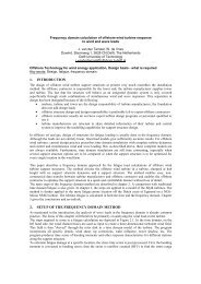
<strong>Frequency</strong> <strong>Domain</strong><strong>Fatigue</strong>in the Design of Support Structuresfor Offshore Wind Turbinesby Jan van der TempelWybren de Vries
Current method: Time <strong>Domain</strong>• full turbine model• all aerodynamics• control• generator
Current method: Time <strong>Domain</strong>• loads are non-linear: related to V 2• rotating system• all details should be incorporated• > 100 load combinations of wind and waves• 5 x 20 minutes or 1 x 60 min, expert opinions differ• total time for 1 fatigue check: 12 - 24 - 48 hours
Current method: Time <strong>Domain</strong>• Offshore contractor does not have specialist software• Turbine manufacturer reluctant to share details• No real optimisation of support structures• Insufficient mutual understanding• Site specific optimisation very difficult
Offshore contractorWind turbine manufacturerDesign supportstructureIntegrated modelMetoceandataLoad caseswind & wavesH sT zTime domainfatigue checksnoOK?<strong>Fatigue</strong> checkresultsyesDone
Offshore: <strong>Frequency</strong> <strong>Domain</strong>• nat. freq.: 0.25 Hz• also fatigue driven• main loading: waves• Morison equation:• F=C d A u 2 + C m B u• Also non-linear!!
Offshore: <strong>Frequency</strong> <strong>Domain</strong>wavespectrumS(f )ftransferfunctionˆ σˆ ζfresponsespectrumS σ(f )f
Offshore: <strong>Frequency</strong> <strong>Domain</strong>wavespectrumS(f )ftransferfunctionˆ σˆ ζfresponsespectrumS σ(f )f
<strong>Frequency</strong> <strong>Domain</strong> Calculations• Calculating time for full scatter diagram, > 100 cases:10 s. to 1 minute• Easy optimisation
New methodGoal:• Make frequency domain fatigue method• Restricted information transfer• But enough to be accurate• Enhance mutual understanding
New methodRequirement:• Leave contractual boundaries• Shift boundary to bearing
Turbine modellingwindrigid• Full time domain• all wind speed classes: 4, 6, 8 .. 26 m/s• rigid support: no dynamics• find tower top force• transfer to frequency domainspectral density [(m/s) 2 s]Improved Von Karman time simulation10 2Improved Von Karman theoretical10 110 010 -110 -2InputOutputResponse spectrum tower top load[N 2 *s]10 1010 910 810 710 610 510 3 <strong>Frequency</strong> [Hz]10 11 <strong>Frequency</strong> [Hz]10 -30 0.5 1 1.5 210 40 0.5 1 1.5 2 2.5 3 3.5 4
Tower modelling (1/2)F top• any FEM program• select 1 or several spots• make transfer function for tower top load
Add aerodynamic dampingF top7000600050004000300020001000TRF without aerodynamic dampingTRF with aerodynamic dampingTRF tower top load tomudline bending stress [(N/m 2 )/N]00 0.5 1 1.5 2<strong>Frequency</strong> [Hz]
<strong>Frequency</strong> domain wind stressInputspectral density [(m/s) 2 s]Improved Von Karman time simulation10 2Improved Von Karman theoretical10 110 010 -110 -2Wind10 3 <strong>Frequency</strong> [Hz]TRF top force10 -30 0.5 1 1.5 2TRF stressTRFResponse spectrum tower top load[N 2 *s]10 11 <strong>Frequency</strong> [Hz]10 1010 910 810 710 610 5TRF tower top load tomudline bending stress [(N/m 2 )/N]7000600050004000300020001000TRF without aerodynamic dampingTRF with aerodynamic damping10 400 0.5 1 1.5 20 0.5 1 1.5 2 2.5 3 3.5 4<strong>Frequency</strong> [Hz]Stress responseOutputResponse spectrummudline bending stress [(N/m 2 ) 2 *s)]2.521.510.53 x 1012 <strong>Frequency</strong> [Hz]Time domain simulationincluding aerodynamic damping<strong>Frequency</strong> domain calculationincluding aerodynamic damping00 0.5 1 1.5 2
Compare FD - TD• perfect match• small deviationat 3PResponse spectrummudline bending stress [(N/m 2 ) 2 *s)]2.521.510.53 x 1012 <strong>Frequency</strong> [Hz]Time domain simulationincluding aerodynamic damping<strong>Frequency</strong> domain calculationincluding aerodynamic damping00 0.5 1 1.5 2
Tower modelling (2/2)• same FEM program• select 1 or several spots• make transfer function for wave loadagain:aerodynamic dampingTRF tower top load tomudline bending stress [(N/m 2 )/N]7000600050004000300020001000TRF without aerodynamic dampingTRF with aerodynamic damping00 0.5 1 1.5 2<strong>Frequency</strong> [Hz]
CombiningwavespectrumS(f )fS(f )fwindspectrumtransferfunctionˆ σˆ ζfˆ σVˆwindftransferfunctionresponsespectrumS σ(f )f+S σ(f )fresponsespectrumS σ(f )f
Validation: Blyth• EU-project OWTES• Vestas V66, fully measured• full model in Bladed by Garrad-Hassan• assistance of Vestas• model checked with measurements
Validation: Blyth
Validation: Blyth• very good comparison• wave influence low• nearly no resonance• fatigue not really an issue• only turbine to get data from• apply on real design with more fatigue
Design comparison: Egmond• design of NM92• 2.75 MW turbines• nat. freq.: 0.31Hz• NM92 abandoned• Available for study
Design comparison: Egmond• wave scatter diagram per wind speed• 112 cases• full TD simulation• FD calculation
Design comparison: EgmondOutcome:• TD: D life, 20 years = 0.56• FD: D life, 20 years = 0.52
Conclusions• The method works!• Effective separation of support structure and turbine• Enabling offshore contractor to optimise structure• Fast checking (1 minute)• Enhancing understanding
Outlook• Current design check of V90 design at Egmond• Adjusting contractor's tools• Improvement of aerodynamic damping calculation• Testing for tripods and jackets• Full PhD thesis available from January 2006