On the design of monopile foundations with respect to static and ...
On the design of monopile foundations with respect to static and ...
On the design of monopile foundations with respect to static and ...

Create successful ePaper yourself
Turn your PDF publications into a flip-book with our unique Google optimized e-Paper software.
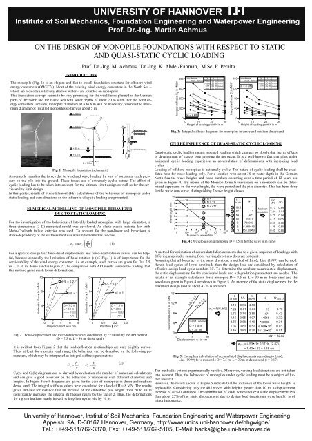
UNIVERSITY OF HANNOVERInstitute <strong>of</strong> Soil Mechanics, Foundation Engineering <strong>and</strong> Waterpower EngineeringPr<strong>of</strong>. Dr.-Ing. Martin AchmusON THE DESIGN OF MONOPILE FOUNDATIONS WITH RESPECT TO STATICAND QUASI-STATIC CYCLIC LOADINGPr<strong>of</strong>. Dr.-Ing. M. Achmus, Dr.-Ing. K. Abdel-Rahman, M.Sc. P. PeraltaINTRODUCTIONThe <strong>monopile</strong> (Fig. 1) is an elegant <strong>and</strong> fast-<strong>to</strong>-install foundation structure for <strong>of</strong>fshore windenergy converters (OWEC’s). Most <strong>of</strong> <strong>the</strong> existing wind energy converters in <strong>the</strong> North Sea –which are located in relatively shallow water – are founded on <strong>monopile</strong>s.This foundation concept seems <strong>to</strong> be very promising for <strong>the</strong> wind farms planned in <strong>the</strong> Germanparts <strong>of</strong> <strong>the</strong> North <strong>and</strong> <strong>the</strong> Baltic Sea <strong>with</strong> water depths <strong>of</strong> about 20 <strong>to</strong> 40 m. For <strong>the</strong> wind energyconverters foreseen, <strong>monopile</strong> diameters <strong>of</strong> 6 <strong>to</strong> 8 m will be necessary, whereas <strong>the</strong> maximumdiameter <strong>of</strong> installed <strong>monopile</strong>s so far was about 5 m.+ 190 m+ 130 mHh400 dense D L160med. dense 7.5 m 30 m7.5 m 20 m5 m 30 m300 5 m 20 m120200 80100 40dense D Lmed. dense 7.5 m 30 m7.5 m 20 mH = 8 MN 5 m 30 m5 m 20 mH = 8 MN0 00 10 20 30 0 10 20 30Height <strong>of</strong> loading point h in mHeight <strong>of</strong> loading point h in mFig. 3: Integral stiffness diagrams for <strong>monopile</strong>s in dense <strong>and</strong> medium dense s<strong>and</strong>.+ 30 m+ _ 0.0 mD = 7.5 mFig. 1: Monopile foundation (schematic)NUMERICAL MODELLING OF MONOPILE BEHAVIOURDUE TO STATIC LOADINGFor <strong>the</strong> investigation <strong>of</strong> <strong>the</strong> behaviour <strong>of</strong> laterally loaded <strong>monopile</strong>s <strong>with</strong> large diameters, athree-dimensional (3-D) numerical model was developed. An elas<strong>to</strong>-plastic material law <strong>with</strong>Mohr-Coulomb failure criterion was used. To account for <strong>the</strong> non-linear soil behaviour, astress-dependency <strong>of</strong> <strong>the</strong> stiffness modulus was implemented as follows:⎛ σκ σ(1)σ ⎟ ⎞E S=at⎜⎝ at ⎠For a specific <strong>design</strong> task force-head displacement <strong>and</strong> force-head rotation curves can be helpful,because especially <strong>the</strong> limitation <strong>of</strong> head rotation φ (cf. Fig. 1) is <strong>of</strong> importance for <strong>the</strong>serviceability <strong>of</strong> <strong>the</strong> wind energy converter. As an example, such curves are given for D = 7.5m, L = 30 m, dense s<strong>and</strong> in Figure 2. The comparison <strong>with</strong> API results verifies <strong>the</strong> finding thatthis method gives much lower deformations.LDt (wall thickness)A <strong>monopile</strong> transfers <strong>the</strong> forces due <strong>to</strong> wind <strong>and</strong> wave loading by way <strong>of</strong> horizontal earth pressureon <strong>the</strong> pile in<strong>to</strong> <strong>the</strong> ground. These forces are <strong>of</strong> extremely cyclic nature. The effect <strong>of</strong>cyclic loading has <strong>to</strong> be taken in<strong>to</strong> account for <strong>the</strong> ultimate limit <strong>design</strong> as well as for <strong>the</strong> serviceabilitylimit <strong>design</strong>.In this poster, results <strong>of</strong> Finite Element (FE) calculations <strong>of</strong> <strong>the</strong> behaviour <strong>of</strong> <strong>monopile</strong>s under<strong>static</strong> loading <strong>and</strong> considerations on <strong>the</strong> influence <strong>of</strong> cyclic loading are presented.12 12h/L = 0.28 8h/L = 1 h/L = 14 D = 7.5 m 4D = 7.5 mL = 30 mL = 30 mFEMFEMAPIAPI0 00 2 4 6 8 0 0.1 0.2 0.3Displacement w in cmRotation o in °It is evident from Figure 2 that <strong>the</strong> load-deflection relationships are only slightly curved.Thus, at least for a certain load range, <strong>the</strong> behaviour can be described by <strong>the</strong> following parameters,which may be interpreted as integral stiffness parameters:λh/L = 0.2Fig. 2 : Force-displacement <strong>and</strong> force-rotation curves determined by FEM <strong>and</strong> by <strong>the</strong> API method(D = 7.5 m, L = 30 m, dense s<strong>and</strong>).HC w=wHC φ =φC w(h) <strong>and</strong> C φ(h) diagrams can be derived by evaluation <strong>of</strong> a number <strong>of</strong> numerical calculations<strong>and</strong> can give a good overview on <strong>the</strong> behaviour <strong>of</strong> <strong>monopile</strong>s <strong>with</strong> different diameters <strong>and</strong>lengths. In Figure 3 such diagrams are given for <strong>the</strong> case <strong>of</strong> <strong>monopile</strong>s in dense <strong>and</strong> mediumdense s<strong>and</strong>. The integral stiffness values were calculated for a load <strong>of</strong> H = 8 MN. The resultsgiven indicate for instance that an increase <strong>of</strong> <strong>the</strong> embedded pile length from 20 <strong>to</strong> 30 msignificantly increases <strong>the</strong> integral stiffnesses nearly by <strong>the</strong> fac<strong>to</strong>r 2. Thus, <strong>the</strong> deformationsfor a given load are nearly halved by leng<strong>the</strong>ning <strong>the</strong> pile by 10 m.(2)ON THE INFLUENCE OF QUASI-STATIC CYCLIC LOADINGQuasi-<strong>static</strong> cyclic loading means repeated loading which changes so slowly that inertia effectsor development <strong>of</strong> excess pore pressure do not occur. It is a well-known fact that piles underhorizontal cyclic loading experience an accumulation <strong>of</strong> deformations <strong>with</strong> increasing loadcycles.Loading <strong>of</strong> <strong>of</strong>fshore <strong>monopile</strong>s is extremely cyclic. The nature <strong>of</strong> cyclic loading shall be elucidatedhere for wave loading only. For a location <strong>with</strong> about 30 m water depth in <strong>the</strong> GermanNorth Sea <strong>the</strong> wave heights <strong>and</strong> wave numbers occurring over a time-period <strong>of</strong> 12 years aregiven in Figure 4. By means <strong>of</strong> <strong>the</strong> Morison formula waveloads on a <strong>monopile</strong> can be determineddependent on <strong>the</strong> wave height, <strong>the</strong> wave period <strong>and</strong> <strong>the</strong> pile diameter. This has been donefor <strong>the</strong> wave sum curve, distinguishing 7 wave height classes.Wave height in mHorizontal Force H in MN201 : N = 118162 : N = 13163 : N = 47112 1248 854 462700 100410610810 1010Number <strong>of</strong> waves N in 11612840H mwin m N1 18.5 1234517141061347114515736000667316.969 10151.28 106MorisonequationH inMN8.137.245.754.152.661.350.45Fig. 4 : Waveloads on a <strong>monopile</strong> D = 7.5 m for <strong>the</strong> wave sum curveh/L = 0.5h/L = 1.0S<strong>and</strong>, denseD = 7.5 mL = 30 m0 5 10Displacement w 1 in cmw 1 = f (H, h/L)Hin MNh/L8.13 0.847.24 0.815.75 0.744.15 0.652.66 0.681.35 0.800.45 0.80w 1in cm4.533.862.851.971.100.520.20Fig. 5: Exemplary calculation <strong>of</strong> accumulated displacements according <strong>to</strong> Lin &Liao (1999) for a <strong>monopile</strong> D = 7.5 m, L = 30 m in dense s<strong>and</strong> (t = 0.17)N1134711451573600066.969 106h/L0.840.810.740.650.680.800.80A method for estimation <strong>of</strong> accumulated displacements due <strong>to</strong> a given sequence <strong>of</strong> loadings <strong>with</strong>differing amplitudes coming from varying directions does yet not exist.Assuming that all loads act in <strong>the</strong> same direction, a method <strong>of</strong> Lin & Liao (1999) can be used.Herein load cycles <strong>of</strong> lower amplitude than <strong>the</strong> <strong>design</strong> load are considered by calculation <strong>of</strong>effective <strong>design</strong> load cycle numbers N * . To determine <strong>the</strong> resultant accumulated displacement,<strong>the</strong> <strong>static</strong> displacements for <strong>the</strong> considered loads <strong>and</strong> a degradation parameter t are needed. Theresults <strong>of</strong> an example calculation for a <strong>monopile</strong> D = 7.5 m, L = 30 m in dense s<strong>and</strong> <strong>and</strong> <strong>the</strong>waveloads given in Figure 4 are shown in Figure 5. An increase <strong>of</strong> <strong>the</strong> <strong>static</strong> displacement for <strong>the</strong>maximum <strong>design</strong> load <strong>of</strong> about 43 % is obtained.N* (t=0.17)13.735.422.320.310.030.01151.28 10ΣN* = 12.82w Ges = 4.53 (1+ 0.17 ln 12.82)= 1.43 4.53 = 6.48 cmThe method is yet not experimentally verified. Moreover, varying load directions are not takenin<strong>to</strong> account. Thus, <strong>the</strong> behaviour <strong>of</strong> <strong>monopile</strong>s under cyclic loading must be a subject <strong>of</strong> fur<strong>the</strong>rresearch.However, <strong>the</strong> results shown in Figure 5 indicate that <strong>the</strong> influence <strong>of</strong> <strong>the</strong> lower wave heights isneglectable. Considering only <strong>the</strong> 485 waves <strong>with</strong> heights greater than 10 m, a displacementincrease <strong>of</strong> 40% is obtained. The contribution <strong>of</strong> loads which induce a <strong>static</strong> displacement lessthan about 25% <strong>of</strong> <strong>the</strong> <strong>static</strong> displacement due <strong>to</strong> <strong>design</strong> load (maximum wave height) is <strong>of</strong>minor importance.University <strong>of</strong> Hannover, Institut <strong>of</strong> Soil Mechanics, Foundation Engineering <strong>and</strong> Waterpower EngineeringAppelstr. 9A, D-30167 Hannover, Germany, http://www.unics.uni-hannover.de/nhgwigbe/Tel.: ++49-511/762-3370, Fax: ++49-511/762-5105, E-Mail: hacks@igbe.uni-hannover.de
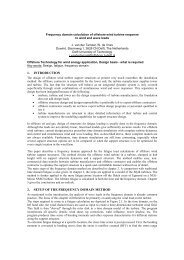
Copenhagen Offshore Wind 2005Pr<strong>of</strong>. Dr. Martin Achmus, Dr. Khalid Abdel-Rahman, M. Sc. Proserpine PeraltaUniversity <strong>of</strong> HannoverInstitute <strong>of</strong> Soil Mechanics, Foundation Engineering <strong>and</strong> Waterpower EngineeringAppelstraße 9 A, D-30167 Hannover, Germany<strong>On</strong> <strong>the</strong> <strong>design</strong> <strong>of</strong> <strong>monopile</strong> <strong>foundations</strong> <strong>with</strong> <strong>respect</strong> <strong>to</strong> <strong>static</strong><strong>and</strong> quasi-<strong>static</strong> cyclic loadingTopic: Offshore technology for wind energy application / Design basis – Foundation conceptsKeywords: Monopile foundation, Numerical modelling, Cyclic loading.Abstract:Most <strong>of</strong> <strong>the</strong> existing wind energy converters in <strong>the</strong> North Sea are founded on <strong>monopile</strong>s, <strong>and</strong>this foundation concept seems also very promising for <strong>the</strong> wind farms planned in <strong>the</strong> Germanparts <strong>of</strong> <strong>the</strong> North <strong>and</strong> <strong>the</strong> Baltic Sea <strong>with</strong> water depths <strong>of</strong> about 20 <strong>to</strong> 40 m. For <strong>the</strong> windenergy converters foreseen, <strong>monopile</strong> diameters <strong>of</strong> 6 <strong>to</strong> 8 m will be necessary.The <strong>design</strong> <strong>of</strong> horizontally loaded <strong>of</strong>fshore piles is commonly done using <strong>the</strong> p-y-curvemethod according <strong>to</strong> <strong>the</strong> API regulations. In this regulation, p-y-curve approaches for <strong>static</strong> aswell as for cyclic loading are given. But, <strong>the</strong> admissibility <strong>of</strong> this method for large-diameterpiles is not proved.A three-dimensional numerical model for <strong>the</strong> investigation <strong>of</strong> <strong>the</strong> <strong>monopile</strong> behaviour undermono<strong>to</strong>nous loading was developed. In this model <strong>the</strong> non-linear material behaviour <strong>of</strong> <strong>the</strong>subsoil is described using an elas<strong>to</strong>-plastic constitutive model <strong>with</strong> a stress-dependentstiffness formulation. Results <strong>of</strong> a parametric study <strong>with</strong> different pile geometries, soil <strong>and</strong>loading conditions are presented <strong>and</strong> compared <strong>with</strong> results from <strong>the</strong> API method for s<strong>and</strong>ysoils. The comparison indicates that <strong>the</strong> API method is not in general suitable for <strong>the</strong> <strong>design</strong> <strong>of</strong>large-diameter piles.Subsequently, cyclic loading <strong>of</strong> <strong>monopile</strong>s is considered. An overview is given on <strong>the</strong> nature<strong>of</strong> cyclic loads due <strong>to</strong> wave loading. The API approach for cyclic loading appears not suitable<strong>to</strong> cover <strong>the</strong> loading conditions. Existing methods <strong>to</strong> deal <strong>with</strong> such loads are presented <strong>and</strong>discussed. It is shown that at <strong>the</strong> time being no reliable method exists <strong>to</strong> estimate accumulateddisplacements under cyclic loads <strong>of</strong> varying amplitudes <strong>and</strong> directions. Possible ways <strong>of</strong>dealing <strong>with</strong> cyclic loading in <strong>the</strong> <strong>design</strong> <strong>of</strong> <strong>monopile</strong>s are discussed.
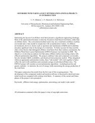
<strong>On</strong> <strong>the</strong> <strong>design</strong> <strong>of</strong> <strong>monopile</strong> <strong>foundations</strong> <strong>with</strong> <strong>respect</strong> <strong>to</strong> <strong>static</strong><strong>and</strong> quasi-<strong>static</strong> cyclic loadingMartin Achmus, Khalid Abdel-Rahman, Proserpine Peralta1 IntroductionThe <strong>monopile</strong> (Fig. 1) is an elegant <strong>and</strong> fast-<strong>to</strong>-install foundation structure for <strong>of</strong>fshore windenergy converters (OWEC’s). Most <strong>of</strong> <strong>the</strong> existing wind energy converters in <strong>the</strong> North Sea –which are located in relatively shallow water – are founded on <strong>monopile</strong>s.This foundation concept seems also very promising for <strong>the</strong> wind farms planned in <strong>the</strong> Germanparts <strong>of</strong> <strong>the</strong> North <strong>and</strong> <strong>the</strong> Baltic Sea <strong>with</strong> water depths <strong>of</strong> about 20 <strong>to</strong> 40 m. For <strong>the</strong> windenergy converters foreseen, <strong>monopile</strong> diameters <strong>of</strong> 6 <strong>to</strong> 8 m will be necessary, whereas <strong>the</strong>maximum diameter <strong>of</strong> installed <strong>monopile</strong>s so far was about 5 m.+ 190 m+ 130 mHh+ 30 mLt (wall thickness)+ _ 0.0 mDD = 7.5 mFigure 1. Monopile foundation (schematic).Decisive for <strong>the</strong> <strong>design</strong> <strong>of</strong> OWEC <strong>foundations</strong> in general is <strong>the</strong> loading by horizontal forces<strong>and</strong> bending moments induced by wind, current <strong>and</strong> wave loads <strong>and</strong> (in <strong>the</strong> Baltic Sea) alsoby ice loads. A <strong>monopile</strong> transfers <strong>the</strong>se forces by way <strong>of</strong> horizontal earth pressure on <strong>the</strong> pilein<strong>to</strong> <strong>the</strong> ground. Especially wind <strong>and</strong> wave loads are <strong>of</strong> extremely cyclic nature. The effect <strong>of</strong>cyclic loading has <strong>to</strong> be taken in<strong>to</strong> account for <strong>the</strong> ultimate limit <strong>design</strong> as well as for <strong>the</strong>serviceability limit <strong>design</strong>.Concerning <strong>the</strong> <strong>design</strong> <strong>of</strong> <strong>monopile</strong>s, in <strong>the</strong> current regulations (DNV 2004, GL 1999)reference is made <strong>to</strong> a special subgrade reaction method (p-y curve method) given in API(2000). However, this method was formerly only used for piles <strong>with</strong> diameters <strong>of</strong> up <strong>to</strong> about3 m, <strong>and</strong> questions arise concerning <strong>the</strong> transfer <strong>of</strong> <strong>the</strong> method <strong>to</strong> very large-diameter piles (e.g. Wiemann & Lesny 2004, Abdel-Rahman & Achmus 2005).In this paper, results <strong>of</strong> Finite Element (FE) calculations <strong>of</strong> <strong>the</strong> behaviour <strong>of</strong> <strong>monopile</strong>s under<strong>static</strong> loading <strong>and</strong> considerations on <strong>the</strong> influence <strong>of</strong> cyclic loading are presented.
Achmus, Abdel-Rahman, Peralta: <strong>On</strong> <strong>the</strong> <strong>design</strong> <strong>of</strong> <strong>monopile</strong> <strong>foundations</strong> 22 Design <strong>of</strong> <strong>monopile</strong>s due <strong>to</strong> current regulationsThe <strong>design</strong> procedure for OWEC <strong>foundations</strong> is in Germany given in <strong>the</strong> Germanische Lloydrules <strong>and</strong> regulations (GL 1999). In this regulation concerning <strong>the</strong> behaviour <strong>of</strong> piles underhorizontal loading reference is made <strong>to</strong> <strong>the</strong> regulation code <strong>of</strong> <strong>the</strong> American PetroleumInstitute (API 2000). The Norwegian guidelines (DNV 2004) also refer <strong>to</strong> <strong>the</strong> API code.In <strong>the</strong> API code <strong>the</strong> p-y method is recommended for <strong>the</strong> <strong>design</strong> <strong>of</strong> horizontally loaded piles.This method is in principle a subgrade modulus method <strong>with</strong> non-linear <strong>and</strong> depth-dependentload-deformation (p-y) characteristics <strong>of</strong> <strong>the</strong> soil springs.As <strong>the</strong> focus in this paper lies on <strong>monopile</strong> <strong>foundations</strong> in s<strong>and</strong>y soils, <strong>the</strong> API procedure <strong>to</strong>construct p-y curves for s<strong>and</strong>y soils is outlined briefly:1) The ultimate lateral resistance per unit length p u is taken as <strong>the</strong> minimum <strong>of</strong> twoexpressions. The first one is valid for shallow depths, whereas <strong>the</strong> second is valid for greaterdepths:= c z + c D '(1)( ) zp us 1 2γp udc3 Dγ' z= (2)Herein z is <strong>the</strong> given depth in metres, D is <strong>the</strong> pile diameter in metres, γ’ is <strong>the</strong> effective unitweight <strong>of</strong> soil (kN/m 3 ). The coefficients c 1 , c 2 , c 3 are dependent on <strong>the</strong> friction angle <strong>of</strong> <strong>the</strong>soil.2) The p-y curve is given at a specific depth by <strong>the</strong> following expression:⎛ k z ⎞p = A p⎜ y⎟utanh (3)⎝ A pu⎠where A = 3.0−0.8z / D ≥ 0.9 for <strong>static</strong> loading <strong>and</strong> A = 0. 9 for cyclic loading, p is <strong>the</strong> soilresistance per unit length, y is <strong>the</strong> actual lateral deflection <strong>and</strong> k is <strong>the</strong> initial modulus <strong>of</strong>subgrade reaction determined as a function <strong>of</strong> <strong>the</strong> friction angle.Load-displacement <strong>and</strong> load-rotation curves determined <strong>with</strong> this method for a <strong>monopile</strong> D =7.5 m, L = 30 m embedded in s<strong>and</strong> (ϕ’ = 35°) are given in Figure 2 for <strong>static</strong> as well as forcyclic loading. Even for high <strong>design</strong> load levels <strong>with</strong> H = 16 MN <strong>and</strong> h = L = 30 m <strong>the</strong>displacements lie in a range which might be admissible concerning <strong>the</strong> serviceability <strong>of</strong> <strong>the</strong>structure. Due <strong>to</strong> <strong>the</strong> API method, <strong>the</strong> effect <strong>of</strong> cyclic loading leads only <strong>to</strong> a relatively slightincrease <strong>of</strong> deformations.Horizontal Force H in MN16 16h/L = 0 h/L = 012 128 h/L = 1 8h/L = 14 4<strong>static</strong><strong>static</strong>cycliccyclic0 00 2 4 6 8 0 0.1 0.2 0.3Displacement w at sea ground level in cm Rotation O at sea ground level in °Figure 2. Monopile deformations according <strong>to</strong> API method (D = 7.5 m, L = 30 m, t = 9 cm,s<strong>and</strong> ϕ’ = 35°).Horizontal Force H in MN
Achmus, Abdel-Rahman, Peralta: <strong>On</strong> <strong>the</strong> <strong>design</strong> <strong>of</strong> <strong>monopile</strong> <strong>foundations</strong> 3Since <strong>the</strong> API method is not confirmed by experience for piles <strong>of</strong> very large diameters, <strong>the</strong>seresults have <strong>to</strong> be checked. The question is <strong>to</strong> be answered, whe<strong>the</strong>r <strong>the</strong> method can be usedalso for <strong>the</strong> <strong>design</strong> <strong>of</strong> large-diameter piles. This holds both for <strong>static</strong> (<strong>design</strong>) load <strong>and</strong> for <strong>the</strong>effect <strong>of</strong> cyclic loading.3 Numerical modelling <strong>of</strong> <strong>monopile</strong> behaviour due <strong>to</strong> <strong>static</strong> loadingFor <strong>the</strong> investigation <strong>of</strong> <strong>the</strong> behaviour <strong>of</strong> laterally loaded <strong>monopile</strong>s <strong>with</strong> large diameters, athree-dimensional (3-D) numerical model was developed. The computations were done using<strong>the</strong> finite element program system ABAQUS (Abaqus 2004). In order <strong>to</strong> carry out manycalculations for varying boundary <strong>and</strong> loading conditions, a large computer system <strong>with</strong>parallel processor technology was used <strong>to</strong> minimize <strong>the</strong> computation time.The aim <strong>of</strong> <strong>the</strong> investigation was <strong>to</strong> analyse <strong>the</strong> behaviour <strong>of</strong> a large <strong>monopile</strong> in principle <strong>and</strong><strong>to</strong> check whe<strong>the</strong>r <strong>the</strong> API method can be used for such large piles. For that, an idealizedhomogeneous soil consisting <strong>of</strong> medium dense or dense s<strong>and</strong> was considered. A <strong>monopile</strong>diameter <strong>of</strong> D = 7.5 m <strong>and</strong> a wall thickness <strong>of</strong> 9 cm was assumed.The most important item <strong>of</strong> geotechnical numerical modelling is <strong>the</strong> simulation <strong>of</strong> <strong>the</strong> soil’sstress-strain-behaviour. An elas<strong>to</strong>-plastic material law <strong>with</strong> Mohr-Coulomb failure criterionwas used. The soil stiffness is herein represented by a stiffness modulus for oedometriccompression E S <strong>and</strong> a Poisson’s ratio ν. To account for <strong>the</strong> non-linear soil behaviour, a stressdependency <strong>of</strong> <strong>the</strong> stiffness modulus was implemented as follows:⎛ σκ σσ ⎟ ⎞E ⎜S=at(4)⎝ at ⎠Herein σ at = 100 kN/m 2 is a reference (atmospheric) stress <strong>and</strong> σ is <strong>the</strong> current mean principalstress in <strong>the</strong> considered soil element. The parameter κ determines <strong>the</strong> soil stiffness at <strong>the</strong>reference stress state <strong>and</strong> <strong>the</strong> parameter λ rules <strong>the</strong> stress dependency <strong>of</strong> <strong>the</strong> soil stiffness.The material parameters used in <strong>the</strong> calculations are given in Table 1. Concerning moredetails about <strong>the</strong> numerical modelling reference is made <strong>to</strong> Abdel-Rahman & Achmus (2005).λTable 1. Material parameters used for dense s<strong>and</strong> / medium dense s<strong>and</strong>.densemedium denseUnit buoyant weight γ’ 11.0 kN/m 3 11.0 kN/m 3Oedometric stiffness parameter κ 600 400Oedometric stiffness parameter λ 0.55 0.60Poisson’s ratio ν 0.25 0.25Internal friction angle ϕ’ 37.5° 35°Dilation angle ψ 7.0° 5°Cohesion c’ 0.1 kN/m 2 0.1 kN/m 2For an example (D=7.5 m, L=20 m, H = 8 MN, dense s<strong>and</strong>) calculated deflection lines areshown in Figure 3 <strong>and</strong> compared <strong>with</strong> API method results. For a dense s<strong>and</strong>, <strong>the</strong> choice <strong>of</strong> anangle <strong>of</strong> internal friction <strong>of</strong> ϕ’ = 35° seems suitable. This corresponds <strong>with</strong> an initial beddingmodulus <strong>of</strong> k = 22 MN/m 3 . From Figure 3 (left) it is evident that this yields <strong>to</strong>o lowdeflections for <strong>the</strong> practically relevant cases <strong>of</strong> h/L > 0. Better agreement regarding headdeflections is obtained for setting ϕ’ = 32.5° (k = 14 MN/m 3 ) <strong>with</strong> <strong>the</strong> API method, see Figure
Achmus, Abdel-Rahman, Peralta: <strong>On</strong> <strong>the</strong> <strong>design</strong> <strong>of</strong> <strong>monopile</strong> <strong>foundations</strong> 43 right. However, <strong>the</strong> overall deflection lines remain different. Of course, also <strong>the</strong> FE resultsdo not necessarily represent exactly <strong>the</strong> true pile behaviour <strong>and</strong> have thus <strong>to</strong> be checked. But,<strong>the</strong> findings give rise <strong>to</strong> <strong>the</strong> conclusion that <strong>the</strong> API method for large-diameter piles should beused <strong>with</strong> great care, especially concerning <strong>the</strong> choice <strong>of</strong> <strong>the</strong> k-value.0 0h/L = 0 h/L = 05 5h/L = 1 h/L = 110 10D = 7.5 7,5 mD = 7.5 7,5 mL = 20 mL = 20 m15 H = 8 MN15H = 8 MNFEM, denseFEM, FEM, dense dense20API, ϕ´= 35°API, API, ϕ´= ϕ´= 32.5° 35°20-2 0 2 4 6 8 -2 0 2 4 6 8Displacement w in cmDisplacement w in cmFigure 3. Comparison <strong>of</strong> deflection lines determined by FEM <strong>and</strong> by <strong>the</strong> API method(D = 7.5 m, L = 20 m, dense s<strong>and</strong>, H = 8 MN).For a specific <strong>design</strong> task force-head displacement <strong>and</strong> force-head rotation curves can behelpful, because especially <strong>the</strong> limitation <strong>of</strong> head rotation φ (cf. Fig. 1) is <strong>of</strong> importance for<strong>the</strong> serviceability <strong>of</strong> <strong>the</strong> wind energy converter. As an example, such curves are given for D =7.5 m, L = 30 m, dense s<strong>and</strong> in Figure 4. The comparison <strong>with</strong> API results verifies <strong>the</strong> findingstated above that this method gives much lower deformations.12 12h/L = 0.2h/L = 0.28 8h/L = 1 h/L = 14 D = 7.5 m 4D = 7.5 mL = 30 mL = 30 mFEMFEMAPIAPI0 00 2 4 6 8 0 0.1 0.2 0.3Displacement w in cmRotation o in °Figure 4. Force-displacement <strong>and</strong> force-rotation curves determined by FEM <strong>and</strong> by <strong>the</strong> APImethod (D = 7.5 m, L = 30 m, dense s<strong>and</strong>, API: k = 22 MN/m 3 ).It is evident from Figure 4 that <strong>the</strong> load-deflection relationships are only slightly curved.Thus, at least for a certain load range, <strong>the</strong> behaviour can be described by <strong>the</strong> followingparameters, which may be interpreted as integral stiffness parameters:HC w= (5)w
Achmus, Abdel-Rahman, Peralta: <strong>On</strong> <strong>the</strong> <strong>design</strong> <strong>of</strong> <strong>monopile</strong> <strong>foundations</strong> 5HCφ= (6)φC w (h) <strong>and</strong> C φ (h) diagrams can be derived by evaluation <strong>of</strong> a number <strong>of</strong> numerical calculations<strong>and</strong> can give a good overview on <strong>the</strong> behaviour <strong>of</strong> <strong>monopile</strong>s <strong>with</strong> different diameters <strong>and</strong>lengths.In Figure 5 such diagrams are given for <strong>the</strong> case <strong>of</strong> <strong>monopile</strong>s in dense <strong>and</strong> medium denses<strong>and</strong>. The integral stiffness values were calculated for a load <strong>of</strong> H = 8 MN.The results given indicate that an increase <strong>of</strong> <strong>the</strong> embedded pile length from 20 <strong>to</strong> 30 msignificantly increases <strong>the</strong> integral stiffnesses nearly by <strong>the</strong> fac<strong>to</strong>r 2. Thus, <strong>the</strong> deformationsfor a given load are nearly halved by leng<strong>the</strong>ning <strong>the</strong> pile by 10 m.An increase <strong>of</strong> <strong>the</strong> pile diameter from 5 <strong>to</strong> 7.5 m has a similar effect. In this case, <strong>the</strong> integralstiffnesses are at least doubled, i. e. <strong>the</strong> pile deformations at sea bed level are more thanhalved.400 dense D L160med. dense 7.5 m 30 m7.5 m 20 m5 m 30 m300 5 m 20 m120densemed. denseH = 8 MND7.5 m7.5 m5 m5 mL30 m20 m30 m20 m200 80100 40H = 8 MN0 00 10 20 30 0 10 20 30Height <strong>of</strong> loading point h in mHeight <strong>of</strong> loading point h in mFigure 5. Integral stiffness diagrams for <strong>monopile</strong>s in dense <strong>and</strong> medium dense s<strong>and</strong>.4 <strong>On</strong> <strong>the</strong> influence <strong>of</strong> quasi-<strong>static</strong> cyclic loadingQuasi-<strong>static</strong> cyclic loading means repeated loading which changes so slowly that inertiaeffects or development <strong>of</strong> excess pore pressure do not occur. It is a well-known fact that pilesunder horizontal cyclic loading experience an accumulation <strong>of</strong> deformations <strong>with</strong> increasingload cycles.In <strong>the</strong> API method described in section 2, cyclic loading is accounted for by setting <strong>the</strong> fac<strong>to</strong>rA(z) <strong>to</strong> 0.9 (see Eq. 3). This approach has been developed by means <strong>of</strong> in situ tests, in whichdifferent load levels were applied <strong>and</strong> <strong>the</strong>se loads were repeated not more than 100, mostlyless than 50 times (Reese et al. 1974, see also Long & Vanneste 1994). It was believed that<strong>with</strong> subsequent load cycles no significant fur<strong>the</strong>r displacement accumulation occurs.In fact, cyclic accumulation does not end after 100 cycles. The accumulation rate decreases<strong>with</strong> <strong>the</strong> number <strong>of</strong> cycles (shakedown behaviour), but it does not get zero. There are severalapproaches <strong>to</strong> consider this behaviour, e. g. Hettler (1981), Long & Vanneste (1994). Lin &Liao (1999) give <strong>the</strong> following equation for <strong>the</strong> accumulation <strong>of</strong> <strong>the</strong> pile head displacement:w N( 1 t ln N )= w(6)1+
Achmus, Abdel-Rahman, Peralta: <strong>On</strong> <strong>the</strong> <strong>design</strong> <strong>of</strong> <strong>monopile</strong> <strong>foundations</strong> 6Herein w is <strong>the</strong> displacement for <strong>static</strong> loading, N is <strong>the</strong> number <strong>of</strong> load cycles <strong>and</strong> w N is <strong>the</strong>displacement after N cycles. t is a degradation parameter, which is besides o<strong>the</strong>rs a function<strong>of</strong> soil properties <strong>and</strong> loading type (one-way or two-way loading). For one-way loading t is avalue <strong>of</strong> <strong>the</strong> order <strong>of</strong> 0.20. This means for instance, that 1000 load cycles induce an increase<strong>of</strong> <strong>the</strong> pile head displacement <strong>of</strong> about 140%.Loading <strong>of</strong> <strong>of</strong>fshore <strong>monopile</strong>s is extremely cyclic, but it is <strong>of</strong> course not a one-way loading.The nature <strong>of</strong> cyclic loading shall be elucidated here for wave loading only. For a location<strong>with</strong> about 30 m water depth in <strong>the</strong> German North Sea Mittendorf et al. (2004) determined <strong>the</strong>wave heights <strong>and</strong> wave numbers occurring over a time-period <strong>of</strong> 12 years. The resulting wavesum curve <strong>and</strong> <strong>the</strong> wave directions are given in Figure 6. More than 100 million wavescoming from all directions are acting on a structure. The maximum wave height is 18.5 m.20Wave height in m16128404 6 8 100 100 10 10 10 10Number <strong>of</strong> waves N in 1Direction <strong>and</strong> frequency <strong>of</strong> significant wave heights H S0-90°90-180°180-270°270-360°Number <strong>of</strong> wavesH S=0-3m H S=3-6m H S=6->9m13579 2000 675035 74 105574 49 17977 347 10Percentage45.114.716.224.0Figure 6. Wave sum curve <strong>and</strong> wave directions for a location in <strong>the</strong> German North Sea, waterdepth 30 m (Mittendorf et al. 2004).By means <strong>of</strong> <strong>the</strong> Morison formula waveloads on a <strong>monopile</strong> can be determined dependent on<strong>the</strong> wave height, <strong>the</strong> wave period <strong>and</strong> <strong>the</strong> pile diameter. This has been done for <strong>the</strong> wave sumcurve given, distinguishing 7 wave height classes (see Achmus et al. 2005). The results areshown in Figure 7.Wave height in m2016121816128 81 : N = 12 : N = 133 : N = 4714 462704 6 8 100 100 10 10 10 10Number <strong>of</strong> waves N in 1451234567H mwin mN18.5 117 131410631471145157360006.969 10151.28 1066MorisonequationH inMN8.137.245.754.152.661.350.45h/L0.840.810.740.650.680.800.80Figure 7. Waveloads on a <strong>monopile</strong> D = 7.5 m for <strong>the</strong> wave sum curve given in Fig. 6 (cf.Achmus et al. 2005).
Achmus, Abdel-Rahman, Peralta: <strong>On</strong> <strong>the</strong> <strong>design</strong> <strong>of</strong> <strong>monopile</strong> <strong>foundations</strong> 7Eq. (6) is valid only for a cyclic loading <strong>with</strong> constant load amplitude. The problem <strong>to</strong> besolved is <strong>to</strong> derive an equivalent number <strong>of</strong> <strong>design</strong> load cycles, which has <strong>the</strong> same effect as<strong>the</strong> actual loads <strong>with</strong> varying amplitudes.Lin & Liao (1999) proposed <strong>the</strong> following equation <strong>to</strong> calculate equivalent load numbers N * :1⎛w⎜ 1, k* t⎝ w1,1k= e( 1+t ln N )⎞⎟k −1⎠N (7)Herein w 1,1 is <strong>the</strong> <strong>static</strong> displacement under <strong>design</strong> load, w 1,k is <strong>the</strong> <strong>static</strong> displacement under<strong>the</strong> load <strong>of</strong> different amplitude <strong>and</strong> N k is <strong>the</strong> number <strong>of</strong> <strong>the</strong>se loads. Summing over all loads <strong>of</strong>different amplitudes, <strong>the</strong> resulting cyclic displacement iswn⎡ ⎛= w1 ,1 ⎢1+tln⎜N1+ ∑⎣ ⎝ k=2*GesN kThe <strong>static</strong> displacements for a given load H <strong>and</strong> height <strong>of</strong> loading point h can be determinedusing <strong>the</strong> force-displacement curves presented in section 3.This method has been applied for <strong>the</strong> waveloads depicted in Fig. 7 <strong>and</strong> a <strong>monopile</strong> D = 7.5 m,L = 30 m embedded in dense s<strong>and</strong>. The results shown in Figure 8 indicate an increase <strong>of</strong> <strong>the</strong><strong>static</strong> displacement for <strong>the</strong> maximum <strong>design</strong> load <strong>of</strong> about 43 %.⎞⎤⎟⎥⎠⎦(8)Horizontal Force H in MN1612840h/L = 0.5h/L = 1.0S<strong>and</strong>, denseD = 7.5 mL = 30 m0 5 10Displacement w 1 in cmw = f (H, h/L)1Hin MN8.137.245.754.152.661.350.45h/L0.840.810.740.650.680.800.80w1in cm4.533.862.851.971.100.520.20N113471145157360006.969 10151.28 1066N* (t=0.17)13.735.422.320.310.030.01ΣN* = 12.82w = 4.53 (1+ 0.17 ln 12.82)Ges= 1.43 4.53 = 6.48 cmFigure 8. Exemplary application <strong>of</strong> Eq. (7) <strong>and</strong> (8) for a <strong>monopile</strong> D = 7.5 m, L = 30 m indense s<strong>and</strong> (t = 0.17).Of course, this method is not experimentally verified. For <strong>the</strong> example, all <strong>the</strong> loads <strong>of</strong> <strong>the</strong> 12year-period acting in different directions were assumed <strong>to</strong> act in one direction. Thus, only aqualitative insight in <strong>the</strong> displacement accumulation process is obtained.However, <strong>the</strong> results indicate that <strong>the</strong> influence <strong>of</strong> <strong>the</strong> lower wave heights is neglectable.Considering only <strong>the</strong> 485 waves <strong>with</strong> heights greater than 10 m, a displacement increase <strong>of</strong>40% is obtained. The contribution <strong>of</strong> loads which induce a <strong>static</strong> displacement less than about25% <strong>of</strong> <strong>the</strong> <strong>static</strong> displacement due <strong>to</strong> <strong>design</strong> load (maximum wave height) is <strong>of</strong> minorimportance.
Achmus, Abdel-Rahman, Peralta: <strong>On</strong> <strong>the</strong> <strong>design</strong> <strong>of</strong> <strong>monopile</strong> <strong>foundations</strong> 85 ConclusionsThe use <strong>of</strong> <strong>the</strong> API method for <strong>the</strong> computation <strong>of</strong> <strong>the</strong> deformations <strong>of</strong> large-diameter<strong>monopile</strong> <strong>foundations</strong> for <strong>of</strong>fshore wind energy plants cannot be generally recommended.This applies <strong>to</strong> <strong>the</strong> <strong>design</strong> for <strong>static</strong> loads <strong>and</strong> particularly <strong>to</strong> <strong>the</strong> estimation <strong>of</strong> <strong>the</strong> influence <strong>of</strong>cyclic loading.For <strong>static</strong> load <strong>design</strong>, numerical investigations are recommended, as <strong>the</strong>y were presented inthis paper. Of course, such investigations are complex <strong>and</strong> time-consuming. For preliminary<strong>design</strong> steps diagrams can be helpful, which allow a simple determination <strong>of</strong> <strong>the</strong> approximatepile deformations <strong>to</strong> be expected for a specific case. However, also <strong>the</strong> numerical calculationsneed verification. Thus, <strong>the</strong> observational method should be used for <strong>the</strong> large-diameter<strong>monopile</strong>s <strong>to</strong> be erected.The behaviour <strong>of</strong> <strong>monopile</strong> <strong>foundations</strong> under cyclic loading <strong>of</strong> varying amplitude <strong>and</strong>direction is up <strong>to</strong> now not well unders<strong>to</strong>od <strong>and</strong> must be a subject <strong>of</strong> future research. At <strong>the</strong>time being no reliable method exists for <strong>the</strong> estimation <strong>of</strong> accumulated displacements undercyclic loads. The analysis procedures presented need verification <strong>and</strong> have <strong>to</strong> be extended <strong>to</strong>deal <strong>with</strong> loads acting in different directions. However, <strong>the</strong> results obtained indicate that onlylarger forces, which occur relatively seldom, have <strong>to</strong> be considered regarding <strong>the</strong>displacement accumulation.The results presented in this paper were obtained in <strong>the</strong> framework <strong>of</strong> <strong>the</strong> FORWIND researchgroup funded by <strong>the</strong> Government <strong>of</strong> <strong>the</strong> federal state <strong>of</strong> Lower Saxony, Germany. The supportis gratefully acknowledged.6 ReferencesAbaqus 2004. User’s Manual. Version 6.4.Abdel-Rahman, K. & Achmus, M. 2005. Finite Element Modelling <strong>of</strong> horizontally loadedMonopile Foundations for Offshore Wind Energy Converters in Germany. InternationalSymposium on Frontiers in Offshore Geotechnics (ISFOG), Perth, Australia, Sept. 2005.Achmus, M. & Abdel-Rahman, K. 2004. Numerische Untersuchung zum Tragverhaltenhorizontal belasteter Monopile-Gründungen für Offshore-Windenergieanlagen. 19.Christian Veder Kolloquium, Graz/Österreich.Achmus, M.; Abdel-Rahman, K.; Peralta, P. 2005. Untersuchungen zum Tragverhalten vonMonopiles für die Gründung von Offshore-Windenergieanlagen. Pfahlsymposium 2005,Braunschweig.API 2000. American Petroleum Institute. Recommended Practice for Planning, Designing<strong>and</strong> Constructing Fixed Offshore Platforms- Working Stress Design, API RecommendedPractice 2A-WSD (RP2A-WSD), 21 st edition, Dallas.DNV 2004. Det Norske Veritas. Design <strong>of</strong> Offshore Wind Turbine Structures. OffshoreSt<strong>and</strong>ard, Norway.GL 1999. Germanischer LIoyd. Rules <strong>and</strong> Regulations, Offshore Wind Energy Converters.Hamburg, Germany.Hettler, A. 1981. Verschiebungen starrer und elastischer Gründungskörper in S<strong>and</strong> beimono<strong>to</strong>ner und zyklischer Belastung. Veröffentlichungen des Instituts für Bodenmechanikund Felsmechanik der Universität Fridericiana in Karlsruhe, Heft 90.Lin, S.-S. & Liao, J.-C. 1999. Permanent strains <strong>of</strong> piles in s<strong>and</strong> due <strong>to</strong> cyclic lateral loads.ASCE Journal <strong>of</strong> Geotechnical <strong>and</strong> Geoenvironmental Engineering, September.Long, J. H. & Vanneste, G. 1994. Effects <strong>of</strong> cyclic lateral loads on piles in s<strong>and</strong>. ASCEJournal <strong>of</strong> Geotechnical Engineering, Vol. 120, No. 1.
Achmus, Abdel-Rahman, Peralta: <strong>On</strong> <strong>the</strong> <strong>design</strong> <strong>of</strong> <strong>monopile</strong> <strong>foundations</strong> 9Mittendorf, K. & Zielke, W. 2004. Extreme Wave Loads on <strong>the</strong> Support Structure <strong>of</strong> OWECs.Proceedings <strong>of</strong> <strong>the</strong> 7 th German Wind Energy Conference (DEWEK), Wilhelmshaven.Mittendorf, K.; Kohlmeier, M.; Zielke, W. 2004. A Hind-Cast Data Base for <strong>the</strong> Design <strong>of</strong>Offshore Wind Energy Structures in <strong>the</strong> German Bight. 29 th International Conference onCoastal Engineering (ICCE), Lisbon.Reese, L. C.; Cox, W. R.; Koop, F. D. 1974. Analysis <strong>of</strong> Laterally Loaded Piles in S<strong>and</strong>.Proceedings <strong>of</strong> <strong>the</strong> VI Annual Offshore Technology Conference. Dallas.Wiemann, J. & Lesny, K. 2004. Evaluation <strong>of</strong> <strong>the</strong> Pile Diameter Effects on Soil-Pile Stiffness.Proceedings <strong>of</strong> <strong>the</strong> 7 th German Wind Energy Conference (DEWEK), 20-21 Oc<strong>to</strong>ber 2004,Wilhelmshaven.