
You also want an ePaper? Increase the reach of your titles
YUMPU automatically turns print PDFs into web optimized ePapers that Google loves.
OURCOMMITMENTTO THEENVIRONMENT<strong>Sodeca</strong> has begun a new stageof study and design of newtrends in ventilation which willhelp to preserve the environmentand to make the energy savingwhich so much concerns today’ssociety.SODECA has concentrated its activity on the production ofindustrial fans, ventilation systems and extractors for the removalof smoke in case of fire since 1983, when it was founded.SODECA’s fans and extractors are present in all Europeancountries and in many parts of the world, thanks to the quality ofthe product and the methods of research and development used.Our quality procedures used and certified by BUREAU VERITAS,in accordance with ISO 9001:2008, are another of the reasonswhich make SODECA one of the best and most renowned fanmanufacturers in Europe.Without a doubt, the most important factor to achieve ourobjectives is the human factor, the great professionals who workat your service, offering not only ventilation equipment but alsosolutions to any ventilation need required by our customers.We sincerely offer you the possibility of visiting our facilities in SantQuirze de Besora, with over 16,000 square metres of built area,where you will be able to see our fan manufacture with perfectclarity and with the highest standards of quality, complying withthe ISO and AMCA standards.This catalogue is only a small part of our possibilities. Do nothesitate to contact us. We will put all our experience and ourhuman resources at your disposal.To obtain an improvementin energy efficiency of fansand of ventilation facilities,the engineering departmentof <strong>Sodeca</strong> has balancedthe energy consumption ofthe fans with their maximumperformance, in the habitualareas of work. This has requireda restructuring of the curvesand their presentation in thisand future <strong>Sodeca</strong> catalogues.Installationsheadquarters ofSODECA s.a.,at Sant Quirzede Besora andmanufacturing plantin Santiagode Chile.
INDUSTRIAL FANSAND EXTRACTORS<strong>Sodeca</strong> has specialised since its inception in the designand manufacture of fans and accessories for industrialapplications.The union of the experience acquired over decades ofwork with fans together with the technology supplied byengineers in different departments has made it possiblefor <strong>Sodeca</strong> to become one of the largest manufacturersof industrial ventilation in the world.The industrial applications require a great capacity foradaptation to the specifications of each project andflexibility in manufacture, so as to fulfil the real needsof each client.In order to fulfil this objective, <strong>Sodeca</strong> has a line ofStandard products and a line of products with specialmanufacture, for the construction of fans adapted tothe demands of our clients.For years constant investments have been made in thedevelopment of internal processes and applicationsto achieve the manufacture and supply of specialindustrial fans, with an extremely limited design andmanufacturing period.Teamwork of our engineering department, togetherwith universities and technology centres as well asclose collaboration between the design departments ofour external collaborators makes it possible to achieveinnovative solutions of industrial ventilation in a shortperiod of time.Throughout our history, we have developed all kinds oftechnology in fans for industrial applications which arecurrently used all over the world. It is our objective tocontinue to invest in this sector so as to continue to beone of the most esteemed manufacturers of industrialfans in the world.
4HCD..............................................42HCH..............................................44HFT..............................................44HCT..............................................44<strong>HTP</strong>..............................................57HGT..............................................70HGTX..............................................70KITS SOBREPRESIÓN..............................................97HPX............................................101HBA............................................104CBD............................................106CBD 3V............................................106CJBD............................................111CJBD/AL............................................111CBX............................................113SV..............................................10SV/PLUS..............................................10SV/ECO..............................................10CL..............................................16CL/PLUS..............................................16NEOLINEO..............................................23CA/LINE..............................................27EDMF..............................................29EDQUIET..............................................30HEP..............................................31HEPT..............................................31HC..............................................36CBXC............................................113CBXR............................................113CBXT............................................113CMR............................................123CAS............................................129CAS-S............................................129CMA............................................135CMP............................................138CJBX............................................145CJBX/AL............................................145CDXR............................................154CDXRT............................................154CJDXR............................................154CSXR............................................162CSXRT............................................162CJSXR............................................162TSA............................................174IN-LINE DUCTFANSAXIALFANSCENTRIFUGAL FANSEC
5CJTX-C............................................275CJLINE............................................284CJSX............................................289CSX............................................295CJSRX............................................295HCDF............................................305HDF............................................305HCH/ATEX............................................308HCT/ATEX............................................308CMA/ATEX............................................312CMP/ATEX............................................314CMR/ATEX............................................318CHT............................................321CVT............................................321HT............................................326CHRE............................................329CTD............................................331CA/ROOF............................................333RECUP............................................335SV/FILTER............................................339UFR............................................343TSAT............................................174CJTSA............................................174CPV............................................182CA............................................187THT............................................190THT/IMP............................................243CI............................................247HTMF............................................249CJBDT/CBDT............................................254TCR............................................258CTMP............................................261TCR/R............................................264CJTCR/R............................................264TCMP............................................269CJMP............................................269FANS FOR THE SMOKEEXTRACTIONFANS FOR ATEX EXPLOSIVEATMOSPHERESROOFFANSHEAT RECOVERYUNITSFILTRATIONUNITS
FANSANDROOF FANSFANSAND IN-LINE EXTRACTORSFANS FORSMOKEEXTRACTIONFANS FOR ATEXEXPLOSIVE ATMOSPHERESAND OTHER APPLICATIONSNEW SERIES - NEW PRODUCTSNEW CATALOGUESNEW BUSINESS OPPORTUNITIESLOW-PRESSURECENTRIFUGAL FANSHEAT RECOVERYSYSTEMS ANDFILTRATION UNITSCENTRIFUGAL FANS FORCOMMERCIAL AND INDUS-TRIAL APPLICATIONSVENTILATION SYSTEMFORHOUSESAsk us forinformationCrta. de Berga, km 0,7E-08580 St. Quirze de BesoraBARCELONA (Spain)Tel: +34 93 852 91 11Fax.+34 93 852 90 42comercial@sodeca.comExport sales: ventilation@sodeca.comwww.sodeca.com
FULFILMENT OF STANDARDSSODECA's fans and extractors comply with the following standards:QUALITYISO 9001:2008Sistemas de gestión de la calidad. Requisitos.Quality management systems -- RequirementsTESTSISO 5801AMCA 210-99UNE 100212:1990ISO 13350ISO 13348Ventiladores industriales. Ensayos de comportamiento en circuitos normalizados.Industrial fans -- Performance testing using standardized airwaysVentiladores industriales. Métodos de ensayos de ventiladores y su representación de ensayos.Laboratory Methods of Testing Fans for Aerodynamic Performance RatingVentiladores. Dispositivos e instalaciones para el ensayo de ventiladores.Ventiladores industriales. Ensayos de comportamiento de ventiladores de chorro.Industrial fans -- Performance testing of jet fansIndustrial fans -- Tolerances, methods of conversion and technical data presentationFANS FOR HIGH TEMPERATURESEN 12101-3:2002 Sistemas de control de humos y calor. Parte 3: Especificaciones para aireadores extractores de humos y calor mecánicos.Smoke and heat control systems - Part 3: Specification for powered smoke and heat exhaust ventilatorsACOUSTICSISO 3744Acústica. Determinación de los niveles de potencia acústica de fuentes de ruido a partir de la presión acústica.Método de ingeniería para condiciones de campo libre sobre un plano reflectante.Acoustics -- Determination of sound power levels of noise sources using sound pressure -- Engineering method in an essentiallyfree field over a reflecting planeBALANCE AND VIBRATIONSISO 1940-1Vibraciones mecánicas. Calidad de equilibradoMechanical vibration -- Balance quality requirements for rotors in a constant (rigid) state -- Part 1: Specification and verificationof balance tolerancesISO 10816-1Vibraciones mecánicas. Evaluación de las vibraciones de máquinasMechanical vibration -- Evaluation of machine vibration by measurements on non-rotating parts -- Part 1: General guidelinesISO 14694Ventiladores industriales. Especificaciones para equilibrado y niveles de vibraciónIndustrial fans -- Specifications for balance quality and vibration levelsSAFETY (Declaration of EC Compliance)EN ISO 12100-1 Seguridad de las máquinas. Conceptos básicos, principios generales para el diseño. Parte 1: Terminología básica, metodología.Safety of machinery -- Basic concepts, general principles for design -- Part 1: Basic terminology, methodologyEN ISO 12100-2 Seguridad de las máquinas. Conceptos básicos, principios generales para el diseño. Parte 2: Principios técnicos.Safety of machinery -- Basic concepts, general principles for design -- Part 2: Technical principlesEN 60204-1Seguridad de las máquinas. Equipo eléctrico de las máquinas. Parte 1: Requisitos generales.Safety of machinery - Electrical equipment of machines - Part 1: General requirementsEN 294Seguridad de máquinas. Distancias de seguridad para impedir que se alcancen zonas peligrosas con los miembros superioresSafety of machinery; safety distances to prevent danger zones from being reached by the upper limbsISO 13857Seguridad de máquinas. Distancias de seguridad para impedir que se alcancen zonas peligrosas con los miembros superiores einferiores. Safety of machinery -- Safety distances to prevent danger zones being reached by upper and lower limbsUNE 100250 Ventiladores industriales. Seguridad mecánica de los ventiladores (equivalente ISO 12499)ISO 12499Ventiladores industriales. Seguridad mécanica en los ventiladoresIndustrial fans -- Mechanical safety of fans -- GuardingDIRECTIVESDirectiva 2006/42/CEDirectiva 2006/95/CEDirectiva 2004/108/CEDirectiva 89/106/CEDirectiva de máquinasMachinery DirectiveDirectiva de baja tensiónLow Voltage DirectiveDirectiva compatibilidad electromagnéticaEMC DirectiveDirectiva productos de construcciónConstruction Products Directive (CPD)ATEX EXECUTIONSDirectiva ATEX 94/9/CEEN 14986EN 13463-1EN 1127-1Aparatos y sistemas de protección para uso en atmósferas potencialmente explosivasEquipment and protective systems intended for use in potentially explosive atmospheresDiseño de ventiladores para trabajar en atmósferas potencialmente explosivas.Design of fans working in potentially explosive atmospheresEquipos no eléctricos destinados a atmósferas potencialmente explosivas. Parte 1: Requisitos y metodología básica.Non-electrical equipment for use in potentially explosive atmospheres - Part 1: Basic method and requirementsAtmósferas explosivas. Prevención y protección contra la explosión. Parte 1: Conceptos básicos y metodología.Explosive atmospheres - Explosion prevention and protection - Part 1: Basic concepts and methodology
Our design, research and developmentdepartment is working intensively to improvethe quality and efficiency of our products day byday.DESIGN, RESEARCH ANDDEVELOPMENTThe modern facilities of our aerodynamic testinglaboratory with an area of 450 m 2 , are the nervecentre for the development of all our products.Here we obtain maximum reliability in the resultsfrom the strict checks to which we subject bothproducts and manufacturing processes.We have also begun a new stage of study anddesign of new trends in ventilation which willhelp to preserve the environment and to makeenergy savings.
SV SV/PLUS SV/ECOSVSV/PLUSSV/ECOSVECSV: Low noise in-line duct fans mounted inacoustic casingSV/PLUS: Low noise in-line duct fans mounted inacoustic casing with 50mm insulationSV/ECO: Low noise in-line duct fans mounted inacoustic casing with 50 mm insulation, fitted with EC motorsFan:• Acoustic casing covered with deadening material• SV: Impeller with backward-curved blades, except models 125-150-200, with multi-bladeimpeller• SV/PLUS: Multi-blade impeller for all models• SV/ECO: Backward-curved impeller for all models• Standard flanged inlet and outlet to aid installation on duct• They are supplied with 4 base stands to aid installation• Linear air circulation• T-models are fitted with 1-5 minute adjustable timer.Motor:• Class F motors with external rotor incorporated thermalprotector, ball bearings and IP54 protection• 220V single-phase. 60Hz. adjustable• Max. air temperature to transport: + 50ºC.• SV/ECO: Highly-efficient brushless-EC motor, electronicallycontrolled by means of a potentiometer of 10KΩ MTP010,or an external signal of 0-10VDCSV/PLUSSV/ECOFinish:• Anticorrosive finish in polyester resin, polymerised at190ºC, after alkaline degreasing and phosphate-freepre-treatment.Order codeSV 150/H (T)60HzSV: In-line duct fansSV/PLUS: In-line duct fans with50mm insulation.Inlet diameterin mmAirflow level.H: High airflowL: Low airflowT Referencesupplied timerSV/ECO: In-line fans for ducts with EC motorTechnical characteristicsModelSpeed(r/min)Maximum admissible current220V (A)Installedpower(kW)Maximumairflow(m 3 /h)Irradiatedsound leveldB(A)Approx. weight(Kg)SV-125/H 2664 0.65 0.08 400 32 5.2SV-125/H-T 2664 0.65 0.08 400 32 5.2SV-150/H 2640 1.25 0.17 560 40 6.8SV-150/H-T 2640 1.25 0.17 560 40 6.8SV-200/H 1488 0.85 0.12 880 44 8SV-200/H-T 1488 0.85 0.12 880 44 8SV-200/L 1536 0.75 0.1 760 42 8SV-250/H 2856 0.95 0.14 1300 48 10.8SV-250/L 2832 0.85 0.12 1000 46 10.8SV-315/H 1596 0.75 0.12 2100 50 21SV-350/H 1536 0.95 0.14 2850 51 28.5SV-400/H 1680 1.8 0.3 3500 53 3810
SV SV/PLUS SV/ECOTechnical characteristicsModel Speed Maximum admissible current (A) InstalledpowerMaximumairflowIrradiatedsound level*Approx. weight(Kg)(r/min)220V(kW)(m 3 /h) dB(A)SV/PLUS-125/H 2802 0.33 0.08 260 30 12SV/PLUS-160/H 2976 0.59 0.14 465 36 13SV/PLUS-200/H 1860 0.72 0.17 700 37 17SV/PLUS-250/H 2498 1.15 0.27 1050 38 18* Sound pressure level dB(A) are measurements at a distance of 1.5 metersModel Speed Maximum admissible current (A) Installed Maximum Sound pressurelevel toApprox. weightpower airflow 50% of maximumspeed *(Kg)(r/min)220V(kW)(m 3 /h)dB(A)SV/ECO-125/H 4480 0.46 0.055 367 29 12.0SV/ECO-160/H 3490 0.99 0.114 565 28 19.0SV/ECO-200/H 3380 1.48 0.192 914 39 24.0SV/ECO-250/H 3220 1.69 0.213 1107 32 24.0SV/ECO-315/H 3580 2.8 0.448 1638 49 31.0* Sound pressure level dB(A) are measurements at a distance of 1.5 metersAcoustic featuresThe specified values are determined according to free field measurements of sound levels in dB(A) at an equivalent distance of twice the fan’sspan plus the impeller’s diameter, with a minimum of 1.5 m.Sound power Lw(A) spectrum in dB(A) via frequency band in Hz.Model 63 125 250 500 1000 2000 4000 8000125/H 22 32 36 34 33 34 30 24150/H 31 41 42 44 45 46 42 36200/H 31 42 47 51 50 47 43 33200/L 29 39 46 47 47 46 45 37250/H 32 42 47 54 55 53 50 41250/L 33 43 47 53 51 50 48 41315/H 34 44 49 56 57 55 52 43350/H 38 48 52 59 60 58 56 47400/H 40 50 54 61 62 60 58 49Model 63 125 250 500 1000 2000 4000 8000SV/PLUS-125/H 35 46 52 57 64 62 55 48SV/PLUS-160/H 43 54 61 66 72 71 67 63SV/PLUS-200/H 43 55 58 62 69 68 66 61SV/PLUS-250/H 49 58 64 70 72 80 70 65Dimensions in mmSVModel A B C1 C2 øD1 L øD2 EC1 EC2 TSV-125/H 310 250 80 201 125 36.5 7 260 200 383SV-150/H 370 290 92 222 150 34.5 7 320 240 439SV-200/H 430 340 117 246 200 34.5 7 380 290 499SV-200/L 430 340 117 246 200 34.5 7 380 290 499SV-250/H 480 395 140 296 250 51.5 7 430 345 583SV-250/L 480 395 140 296 250 51.5 7 430 345 583SV-315/H 565 490 173.5 370 315 55 8.5 515 440 675SV-350/H 650 550 200 410 355 57 8.5 600 500 764SV-400/H 725 610 200 454 400 70 8.5 675 560 86511
SV SV/PLUS SV/ECODimensions in mmSV/PLUSModel A B B1 C C1 øD1 øD2 E FSV/PLUS-125/H 400 410 277 300 171.5 125 12.5 330 440SV/PLUS-160/H 400 410 148.5 300 142.5 160 12.5 330 440SV/PLUS-200/H 444 444 222 420 251.5 200 12.5 364 484SV/PLUS-250/H 444 444 222 420 221.5 250 12.5 364 484SV/ECOModel A B B1 C C1 øD1 øD2 E FSV/ECO-125 400 410 205 325 165.5 125 12.5 330 440SV/ECO-160 550 485 149 340 194.5 160 12.5 405 590SV/ECO-200 600 545 170 425 259.5 200 12.5 465 640SV/ECO-250 600 545 194 425 234.5 250 12.5 465 640SV/ECO-315 675 595 227.5 475 251.5 315 12.5 515 71512
SV SV/PLUS SV/ECOCharacteristic curvesQ = Airflow in m 3 /h, m 3 /s and cfm.Pe = Static pressure in mm.w.c., Pa and inwg.SV13
SV SV/PLUS SV/ECOCharacteristic curvesQ = Airflow in m 3 /h, m 3 /s and cfm.Pe = Static pressure in mm.w.c., Pa and inwg.SVSV/PLUS14
SV SV/PLUS SV/ECOCharacteristic curvesQ = Airflow in m 3 /h, m 3 /s and cfm.Pe = Static pressure in mm.w.c., Pa and inwg.SV/ECO125 160 200250 315AccessoriesSee accessories section.ElectronicspeedcontrollersMTP010RegulatorInput andoutput kitsRectangulargrillesProtectiongrillesCirculargrillesElectricbatteriesButterflyvalvesOutletCaptureopeningsInlet/OutletBackdraughtshuttersAccessoriesAir filterboxesIntelligentsensorsAir intakes forhousesOutputopenings forhousesSilencer15
CLCL/PLUSCLCL/PLUSCL: Low-profile, in-line rectangular duct fans with inspection cover toaid cleaningCL/PLUS: In-line rectangular duct fans with 50mm insulation.Fan:• Galvanized sheet steel casing• Impeller with forward-facing blades made from galvanised sheet steel• External connection box, IP-55 protection, V0 flame-retardantCLCL/PLUSMotor:• Motors with IE-2 efficiency, except lower powers0.75 kW in single-phase motors and two-speedmotors• Class F external rotor motors with ball bearings,IP-54 protection• 220V single-phase. 60Hz., and three-phase220/380V. 60Hz.• Working temperature: -20ºC +50ºCFinish:• Anticorrosive galvanized sheet steel.Order codeCL 250 4T60HzCL: Low-profile rectangularin-line duct fansCL/PLUS: In-line rectangular duct fans with50mm insulation.Impeller sizeNumber ofmotor poles4=1680 r/min. 60 Hz6=1080 r/min. 60 Hz8=900 r/min. 60 HzT=Three-phaseM=Single-phaseTechnical characteristicsModel Speed Maximum admissible current (A) Installedpower(r/min)220V 380V(kW)Maximumairflow(m 3 /h)Irradiated sound pressurelevel at 2/3 of QmaxdB(A) (1)CL-200-4T 1524 0.94 0.54 0.12 1150 52 11CL-200-4M 1380 0.68 0.08 860 51 11CL-225-4T 1452 1.42 0.82 0.3 1700 53 17CL-225-4M 1512 1.9 0.24 1670 53 18CL-225-6T 864 0.73 0.42 0.08 1070 45 16CL-225-6M 972 0.75 0.08 1080 45 16CL-250-4T 1548 2.56 1.48 0.55 2650 55 21CL-250-4M 1608 3.1 0.5 2350 54 23CL-250-6T 1050 1.11 0.64 0.15 1630 49 19CL-250-6M 1080 1.3 0.15 1500 48 21CL-280-4T 1596 4.05 2.34 0.85 3100 60 30CL-280-6T 984 1.42 0.82 0.2 2010 52 27CL-280-6M 852 2.1 0.24 2120 53 28CL-315-4T 1656 7.01 4.05 1.8 4160 65 44CL-315-6T 1020 2.46 1.42 0.37 2820 54 34CL-315-6M 1032 3.15 0.37 2780 54 34CL-355-6T 1008 4.54 2.62 0.85 4200 58 46CL-355-6M 1068 6.2 0.8 4070 58 53CL-355-8T 744 2.15 1.24 0.37 3030 50 43CL-400-6T 1056 7.88 4.55 1.7 7120 63 71CL-400-8T 744 3.67 2.12 0.7 5020 55 66CL-450-6T 1056 12.47 7.2 2.9 8900 64 94CL-450-8T 816 7.38 4.26 1.3 7440 58 85(1) The irradiated sound pressure levels dB(A) are free field measurements at 1 metre.Approx.weight(Kg)16
CLCL/PLUSTechnical characteristicsModel Speed Maximum admissible current (A) AbsorbedPower(r/min)220V 380V(kW) (m 3 /h)dB(A)(Kg)CL/PLUS-200-4M 1416 1.8 0.36 1100 36 21CL/PLUS-225-4M 1500 2.3 0.51 1650 38 23CL/PLUS-250-4M 1428 3 0.69 1900 42 28CL/PLUS-280-4M 1452 5.1 1.15 2900 47 37CL/PLUS-315-4T 1560 4.1 2.5 5050 52 47CL/PLUS-355-4T 1584 6 3.7 6300 58 78CL/PLUS-400-4T 1596 8.1 5 7100 61 99CL/PLUS-400-6T 996 4.9 2.7 7050 50.8 59CL/PLUS-450-4T 1596 8.1 5 7200 62 111CL/PLUS-450-6T 996 4.9 2.7 7800 51.8 60(1) The sound pressure levels dB(A) are free field measurements at 1 metres.MaximumairflowSound pressure level(1) inlet at 1/3 of QmaxApprox.weightAcoustic featuresSound power Lw(A) spectrum in dB(A) via frequency band in Hz.Model 63 125 250 500 1000 2000 4000 8000200-4 44 49 52 53 55 52 48 42225-4 45 50 53 54 56 53 49 43225-6 38 43 46 47 47 44 40 34250-4 47 52 55 56 58 55 51 45250-6 42 47 50 51 51 48 44 38280-4 52 57 60 61 63 60 56 50280-6 45 50 53 54 54 51 47 41315-4 57 62 65 66 68 65 61 55315-6 47 52 55 56 56 53 49 43355-6 51 56 59 60 60 57 53 47355-8 43 48 50 53 51 48 44 39400-6 56 61 64 65 65 62 58 52400-8 48 53 55 58 56 53 49 44450-6 57 62 65 66 66 63 59 53450-8 51 56 58 61 59 56 52 47Model 63 125 250 500 1000 2000 4000 8000CL/PLUS-200-4M 20 22 31 37 40 37 35 35CL/PLUS-225-4M 29 27 33 43 44 38 42 40CL/PLUS-250-4M 34 33 37 43 44 39 39 35CL/PLUS-280-4M 44 37 41 44 48 44 41 40CL/PLUS-315-4T 36 41 40 47 53 48 48 47CL/PLUS-355-4T 41 41 49 55 58 54 52 51CL/PLUS-400-4T 47 48 50 56 63 56 53 53CL/PLUS-400-6T 37 38 40 46 53 46 43 43CL/PLUS-450-4T 45 49 51 59 63 56 53 53CL/PLUS-450-6T 35 39 41 49 53 46 43 43Dimensions in mmCLModel C øD I J J2 K k2 L MCL-200 450 ø9 440 240 220 400 420 200 115CL-225 530 ø9 540 290 270 500 520 250 142CL-250 560 ø9 540 340 320 500 520 300 155CL-280 640 ø9 640 340 320 600 620 300 165CL-315 700 ø9 640 390 370 600 620 350 175CL-355 780 ø9 470 440 420 700 720 400 202CL-400 880 ø9 840 540 520 800 820 500 285CL-450 980 ø9 1040 540 520 1000 1020 500 300CL/PLUSModel A B C C1 I J J2 K K2 LCL/PLUS-200 338 507 417 445 440 240 220 400 420 200CL/PLUS-225 393 605 502 530 540 290 270 500 520 250CL/PLUS-250 443 605 532 560 540 340 320 500 520 300CL/PLUS-280 443 705 612 640 640 340 320 600 620 300CL/PLUS-315 493 705 672 700 640 390 370 600 620 350CL/PLUS-355 562 811 752 780 740 440 420 700 720 400CL/PLUS-400 662 911 852 880 840 540 520 800 820 500CL/PLUS-450 662 1110 952 980 1040 540 520 1000 1020 60017
CLCL/PLUSCharacteristic CurvesQ = Airflow in m 3 /h and m 3 /sPe = Static pressure in mm.w.c. and PaThe radiated sound levels given on the curves are free field pressure measurements at 1 metres.CL18
CLCL/PLUSCharacteristic CurvesQ = Airflow in m 3 /h and m 3 /sPe = Static pressure in mm.w.c. and PaThe radiated sound levels given on the curves are free field pressure measurements at 1 metres.CL19
CLCL/PLUSCharacteristic CurvesQ = Airflow in m 3 /h and m 3 /sPe = Static pressure in mm.w.c. and PaThe radiated sound levels given on the curves are free field pressure measurements at 1 metres.CL20
CLCL/PLUSCharacteristic CurvesQ = Airflow in m 3 /h and m 3 /sPe = Static pressure in mm.w.c. and PaThe radiated sound levels given on the curves are free field pressure measurements at 1 metres.CL21
CLCL/PLUSCharacteristic CurvesQ = Airflow in m 3 /h and m 3 /sPe = Static pressure in mm.w.c. and PaCL/PLUS1.CL/PLUS-200-4M2.CL/PLUS-225-4M3.CL/PLUS-250-4M4.CL/PLUS-280-4M5.CL/PLUS-315-4T6.CL/PLUS-355-4T7.CL/PLUS-400-4T8.CL/PLUS-400-6T9.CL/PLUS-450-4T10.CL/PLUS-450-6TAccessoriesSee accessories section.INT RM RFT RFM SR ARE SA TAC/CL CJFILTER/CL RR22
NEOLINEOIn-line fans for small ducts with removable covers with Long Life ballNEOLINEO bearingsFan:• V0 flame-retardant plastic casing• External terminal board, with variable position• Quick and easy to install• T-models are fitted with timerMotor:• Motors with Long Life ball bearings, IPX4protection, two-speed and adjustable• Single-phase 220380V. 60Hz• Working temperature:-10ºC +60ºCFinish:• Made from white, V0 flame-retardantplasticOrder codeNEOLINEO 100 (Q) (T)60HzNEOLINEO: In-linefans for ducts withremovable coversInlet diameterin mmQ Referencelow airflow levelT Referencesupplied timerTechnical characteristicsModel Speed Maximum admissible current Absorbedmax / min.220VPower(r/min)(A)(W)Maximumairflow(m 3 /h)Irradiatedsound level*dB(A)Approx. weight(Kg)NEOLINEO-100-Q 2940 / 2484 0.07 / 0.05 15 / 12 200 / 155 29 / 25 1.22NEOLINEO-100-Q T 2940 / 2484 0.07 / 0.05 15 / 12 200 / 155 29 / 25 1.22NEOLINEO-100 2604 / 1908 0.11 / 0.09 23 / 20 255 / 180 30 / 25 1.795NEOLINEO-100 T 2604 / 1908 0.11 / 0.09 23 / 20 255 / 180 30 / 25 1.8NEOLINEO-125 2760 / 1920 0.15 / 0.11 33 / 25 365 / 250 33 / 27 1.8NEOLINEO-125 T 2760 / 1920 0.15 / 0.11 33 / 25 365 / 250 33 / 27 1.8NEOLINEO-150 2748 / 1824 0.26 / 0.18 58 / 40 550 / 385 33 / 28 2.4NEOLINEO-150 T 2748 / 1824 0.26 / 0.18 58 / 40 550 / 385 33 / 28 2.4NEOLINEO-160 2748 / 1824 0.26 / 0.18 58 / 40 550 / 385 34 / 28 2.4NEOLINEO-160 T 2748 / 1824 0.26 / 0.18 58 / 40 550 / 385 34 / 28 2.4NEOLINEO-200-Q 3264 / 2136 0.37 / 0.22 75 / 45 950 / 700 36 / 30 3.7NEOLINEO-200 2868 / 2280 0.64 / 0.43 145 / 98 1060 / 790 38 / 32 3.7NEOLINEO-200 T 2868 / 2280 0.64 / 0.43 145 / 98 1060 / 790 38 / 32 3.7NEOLINEO-250-Q 3024 / 2088 0.5 / 0.4 110 / 85 990 / 720 39 / 37 7.1NEOLINEO-250 3168 / 2340 0.78 / 0.48 180 / 110 1350 / 990 40 / 38 7.1NEOLINEO-315 3000 / 2184 1.32 / 0.9 300 / 200 2300 / 1740 47 / 41 11.4(*) The radiated sound pressure levels are free field measurements at 3 metres with rigid tubes during inlet and outlet.23
NEOLINEODimensions in mmModel A B C C1 C2 øD ENEOLINEO-100-Q 231 156 174 82 152 96 95NEOLINEO-100-Q T 231 156 174 82 152 96 95NEOLINEO-100 303 188.5 211 101.5 189 96 90NEOLINEO-100 T 303 188.5 211 101.5 189 96 90NEOLINEO-125 258 188.5 211 101.5 189 122 90NEOLINEO-125 T 258 188.5 211 101.5 189 122 90NEOLINEO-150 294 214.5 234 112.5 212 146 110NEOLINEO-150 T 294 214.5 234 112.5 212 146 110NEOLINEO-160 272.5 214.5 234 112.5 212 156 110NEOLINEO-160 T 272.5 214.5 234 112.5 212 156 110NEOLINEO-200-Q 300 234.5 260.5 125.5 235 196 140NEOLINEO-200 300 234..5 260.5 125.5 235 196 140NEOLINEO-200 T 300 234.5 260.5 125.5 235 196 140NEOLINEO-250-Q 385 300 317 152.5 292 247 176.5NEOLINEO-250 385 300 317 152.5 292 247 176.5NEOLINEO-315 448 361.5 392.5 188.5 359 312 220.5Characteristic CurvesQ = Airflow in m 3 /hPe = Static pressure in mm.w.c., PaMaximum speedMinimum speed24
NEOLINEOCharacteristic CurvesQ = Airflow in m 3 /hPe = Static pressure in mm.w.c., PaMaximum speedMinimum speed25
NEOLINEOCharacteristic CurvesQ = Airflow in m 3 /hPe = Static pressure in mm.w.c., PaMaximum speedMinimum speedAccessoriesSee accessories section.Standardinstallation kit(tube)StandardinstallationplateParallelinstallationkit (flangesand rails)One-wayhatchesFixed grillesElectronicspeedcontrollersAir filterboxesElectricbatteriesDUO twospeed switchIntelligentsensorsAir intakes forhousesOutputopenings forhousesSilencer26
CA/LINECA/LINEIn-line circular fans for ductswith Long Life ball bearingsFan:• Steel sheet casing• External terminal board• Quick and easy to install• Includes base standMotor:• Motors with Long Life ball bearings, IPX4 protection,two-speed and adjustable• Single-phase 220380V. 60Hz• Working temperature:-10ºC +60ºCFinish:• Anticorrosive finish in polyester resin, polymerised at190ºC, after alkaline degreasing and phosphate-freepre-treatment.Size 355Order codeCA/LINE 20060HzCA/LINE: In-line circularfans for ductsInlet diameterin mmTechnical characteristicsModelSpeed(r/min)Maximum admissiblecurrent220V (A)Absorbedelectrical power(kW)Maximumairflow(m 3 /h)Soundpressure leveldB(A)Approx. weight(Kg)CA/LINE-10 2973 0.27 0.063 260 33 3CA/LINE-12 3016 0.29 0.067 350 35 3CA/LINE-15 3003 0.43 0.1 537 41 4CA/LINE-20 3021 0.71 0.162 980 36 5CA/LINE-25 3021 0.71 0.162 1008 38 5CA/LINE-31 2719 1.23 0.285 1596 37 6.5CA/LINE-355 2517 1.56 0.357 2098 39 12Acoustic featuresThe specified values are determined according to free field measurements of sound levels in dB(A) at a distance of 3 m.Sound power Lw(A) spectrum in dB(A) via frequency band in Hz.Model 63 125 250 500 1000 2000 4000 8000100 7 23 16 33 45 44 37 26125 8 17 18 34 43 41 33 22150 10 19 38 40 49 41 40 24200 11 13 21 35 41 36 46 38Model 63 125 250 500 1000 2000 4000 8000250 14 21 29 36 39 37 38 38315 12 20 29 36 36 39 38 35355 12 17 29 37 39 40 39 3827
CA/LINEDimensions in mmModel A B ød øD ECA/LINE-100 206 167 100 245 287CA/LINE-125 206 175 125 245 287CA/LINE-150 227 176 150 345 389CA/LINE-200 227 175 200 345 389CA/LINE-250 230 170 250 345 389CA/LINE-315 257 189 315 402 446Model A B ød øD E øO x X Y ZCA/LINE-355 450 352 354 420 470 10 442 466 135 110Characteristic CurvesQ = Airflow in m 3 /h, m 3 /s and cfm.Pe = Static pressure in mm.w.c., Pa and inwg.28
EDMFEDMFExtra-flat bathroom fans with aesthetic and modern design• Architectural integration with the bath elements• Low sound level• Extra-flat design with just 12.5 mm thickness• High performance thanks to its aerodynamic design• Quick and easy to installBuilt:• White finish• Non-return damper incorporated in allmodels• Manufactured from recyclable materialsMotor:• 220V 60Hz single-phaseVersion• BASIC: functions simultaneously with thelight switch or independently• TIMER: functions with an adjustableelectronic timer• LL: Ball bearingsTechnical characteristicsModelVersionSpeed(r/min)Power(W)Airflow(m 3 /h)Sound level*dB(A)Weight(Kg)EDMF-100 Basic 2300 14 95 34 0.51EDMF-100-T Timer 2300 14 95 34 0.51EDMF-100-LL LL 2300 14 95 34 0.51EDMF-100-LL-T LL/Timer 2300 14 95 34 0.51EDMF-120 Basic 2400 16 180 35 0.61EDMF-120-T Timer 2400 16 180 35 0.61EDMF-120-LL LL 2400 16 180 35 0.61EDMF-150 Basic 2400 24 292 38 0.97EDMF-150-T Timer 2400 24 292 38 0.97EDMF-150-LL LL 2400 24 292 38 0.97* Sound level to 3mDimensions in mmModel A B C DEDMF-100 150 12.5 108 98EDMF-100-T 150 12.5 108 98EDMF-100-LL 150 12.5 108 98EDMF-100-LL-T 150 12.5 108 98EDMF-120 176 12.5 114 124EDMF-120-T 176 12.5 114 124EDMF-120-LL 176 12.5 114 124EDMF-150 205 13 132 149EDMF-150-T 205 13 132 149EDMF-150-LL 205 13 132 149Characteristic curvesQ = Airflow in m 3 /h and m 3 /s.EDMFPe = Static pressure in mm.w.c., PaAccessoriesSee accessories section.DecorativegrilleBackdraughtlouvreElectronicspeedcontrollers29
EDQUIETEDQUIETDomestic extractors with a very low noise level and low power consumption25 dB(A)7.5 W• Architectural integration with the bathelements• Ultra-silent at just 25 dB(A)• High performance thanks to a lowpower7.5W motor• Quick and easy to installBuilt:• White finish• Non-return damper incorporated• Equipped with diffusers that reduce airturbulences and noise levels• Anti-vibration motor mountsthat eliminate vibrations.Motor:• 220V 60 Hz single-phase• Highly-efficient motor• Ball bearings that last over 40,000 hours• Motor base for vibration absorption• Klixon equipped motorVersions:• BASIC: functions simultaneously withthe light switch or independently• TIMER: functions with an adjustableelectronic timerTechnical characteristicsModelVersionSpeed(r/min)Power(W)Airflow(m 3 /h)Sound leveldB(A)Weight(Kg)EDQUIET-100 Basic 2165 7.5 97 25 0.21EDQUIET-100-T Timer 2165 7.5 97 25 0.21* Sound level to 3mDimensions in mmCharacteristic curvesQ = Airflow in m 3 /h and m 3 /s.PaEDQUIETPe = Static pressure in mm.w.c.,Model A B C DEDQUIET 158 26 107 99AccessoriesSee accessories section.DecorativegrilleBackdraughtlouvreElectronicspeedcontrollers30
HEP HEPTHEPHEPTHEP: Wall-mounted axial fans, with IP-65 motorHEPT: Long-cased axial fans, with IP-65 motorWall-mounted axial (HEP) and long-cased fans (HEPT), with fibreglass-reinforcedplastic impeller.Fan:• Airflow direction from motor to impeller• Impeller in polyamide 6 reinforced with fibre glass• HEP: Support frame in sheet steel• HEP: Protection guard, meets UNE 100250 standard• HEPT: Sheet steel long casing• HEPT: Outside connecting box, IP-65 protectionHEPMotor:• Class F motors with ball bearings,IP-65 protection• 220V single-phase. 60Hz.,and three-phase 220/380V. 60 Hz• Working temperature: -25ºC. +60ºC.,4-6-8 poles motors and -25ºC. +45ºC, 2 polemotorsFinish:• Anticorrosive finish in polyester resin,polymerised at 190ºC, after alkalinedegreasing and phosphate-free pre-treatment.On request:• Motor, impeller and guard unit (version F)• Motor-impeller unit (version G)• Airflow direction from impeller to motor• Special windings for different voltagesHEPTOrder codeHEP 45 4T/H I F60HzHEP: Wall-mounted axial fans,with IP-65 motorHEPT: Long-cased axial fans,with IP-65 motorImpellerdiameter in cm.Number of motor poles4=1680 r/min. 60 Hz6=1080 r/min. 60 Hz8=900 r/min. 60 HzT=Three-phaseM=Single-phaseH=High airflowL=Low airflowAir circulationI=ImpellerMotor->ImpellerA=Airflow-inImpeller->MotorExecution of the fanStandardexecutionF=Motor-impellerunitguardG=Motor-impellerunitTechnical characteristicsModelSpeed(r/min)Maximum admissiblecurrent (A)220V 380VAbsorbed powerat free airflow (W)Maximumairflow(m 3 /h)Soundpressure leveldB(A)Approx. weight(Kg)HEP HEPTHEP-25-2T/H 3336 1.3 0.75 250 2300 64 5.3 -HEP-25-2M/H 3300 1.95 - 285 2300 64 5.3 -HEP-25-4T/H 1740 0.69 0.4 87 1250 52 4.5 -HEP-25-4M/H 1728 0.65 - 100 1250 52 4.5 -HEP-31-2T/H HEPT-31-2T/H 3168 1.54 0.89 495 4000 74 7 7.4HEP-31-2M/H HEPT-31-2M/H 3168 2.3 - 515 4000 74 7 7.4HEP-31-4T/H HEPT-31-4T/H 1692 0.69 0.4 115 2400 55 5.7 6.2HEP-31-4M/H HEPT-31-4M/H 1692 0.75 - 140 2400 55 5.7 6.2HEP-31-4T/L 1716 0.69 0.4 100 1950 54 5.1 -HEP-31-4M/L 1704 0.7 - 110 1950 54 5.1 -HEP-35-2T/H HEPT-35-2T/H 3348 2.16 1.25 650 6020 76 8.8 9.4HEP-35-2M/H HEPT-35-2M/H 3210 2.8 - 690 6020 76 8.8 9.431
HEP HEPTTechnical characteristicsModelSpeed(r/min)Maximum admissiblecurrent (A)220V 380VAbsorbed powerat free airflow(W)Maximumairflow(m 3 /h)Soundpressure leveldB(A)Approx. weight(Kg)HEP HEPTHEP-35-4T/H HEPT-35-4T/H 1608 0.74 0.43 170 3500 58 7.1 7.6HEP-35-4M/H HEPT-35-4M/H 1608 0.98 - 180 3500 58 7.1 7.6HEP-35-4T/L 1692 0.69 0.4 110 2650 56 6.5 -HEP-35-4M/L 1692 0.75 - 115 2650 56 6.5 -HEP-40-4T/H HEPT-40-4T/H 1704 2.1 1.2 325 5200 61 10.6 13.5HEP-40-4M/H HEPT-40-4M/H 1680 1.85 - 360 5200 61 10.6 13.5HEP-40-4T/L 1740 2.1 1.2 220 4000 60 10.6 -HEP-40-4M/L 1704 1.55 - 260 4000 60 10.6 -HEP-40-6T/H HEPT-40-6T/H 1152 1.12 0.65 150 3500 54 10.2 13.5HEP-40-6M/H HEPT-40-6M/H 1152 1.06 - 180 3500 54 10.2 13.5HEP-45-4T/H HEPT-45-4T/H 1680 2.11 1.22 470 7300 66 12.5 15.5HEP-45-4M/H HEPT-45-4M/H 1680 2.35 - 480 7300 66 12.5 15.5HEP-45-4T/L 1728 2.1 1.2 315 5810 64 11 -HEP-45-4M/L 1632 1.85 - 360 5810 64 11 -HEP-45-6T/H HEPT-45-6T/H 1146 1.42 0.82 210 4900 56 11.4 15.5HEP-45-6M/H HEPT-45-6M/H 1146 1.4 - 225 4900 56 11.4 15.5HEP-50-4T/H HEPT-50-4T/H 1704 3.1 1.8 720 10150 69 15 18HEP-50-4M/H HEPT-50-4M/H 1656 3.45 - 720 10150 69 15 .0 18HEP-50-4T/L 1680 2.15 1.25 430 7300 67 13 -HEP-50-4M/L 1644 2.3 - 430 7300 67 13 -HEP-50-6T/H HEPT-50-6T/H 1140 1.38 0.8 240 6150 59 13.2 18HEP-50-6M/H HEPT-50-6M/H 1140 1.38 - 245 6150 59 13.2 18HEP-56-4T/H HEPT-56-4T/H 1620 3.63 2.1 1050 12800 72 21 28HEP-56-4M/H HEPT-56-4M/H 1620 5.26 - 1060 12800 72 21 28HEP-56-4T/L 1680 3.2 1.85 800 10900 70 19 -HEP-56-4M/L 1620 3.7 - 810 10900 70 19 -HEP-56-6T/H HEPT-56-6T/H 1098 1.73 1 400 8250 62 17 28HEP-56-6M/H HEPT-56-6M/H 1098 2.25 - 415 8250 62 17 28HEP-63-4T/H HEPT-63-4T/H 1698 6.92 4 1700 18700 82 25.8 33.5HEP-63-4T/L 1650 5.01 2.9 1290 16500 75 23 -HEP-63-4M/L 1650 5.4 - 1295 16500 75 23 -HEP-63-6T/H HEPT-63-6T/H 1086 2.06 1.19 500 12050 65 20.2 33.5HEP-63-6M/H HEPT-63-6M/H 1086 2.7 - 560 12050 65 20.2 33.5HEP-63-6T/L 1134 1.62 0.94 360 9450 63 19.4 -HEP-63-6M/L 1134 1.8 - 330 9450 63 19.4 -HEP-63-8T/H 840 1.9 1.1 325 8250 57 19.2 -HEP-63-8M/H 840 1.89 - 325 8250 57 19.2 -Acoustic featuresThe specified values are determined according to free field measurements of pressure and sound levels in dB(A) at an equivalent distance oftwice the fan’s span plus the impeller’s diameter, with a minimum of 1.5 m.Sound power Lw(A) spectrum in dB(A) via frequency band in Hz.Model 63 125 250 500 1000 2000 4000 800025-2/H 39 52 64 68 70 70 66 5825-4/H 27 40 52 56 58 58 54 4631-2/H 49 62 74 78 80 80 76 6831-4/H 30 43 55 59 61 61 57 4931-4/L 29 42 54 58 60 60 56 4835-2/H 51 64 76 80 82 82 78 7035-4/H 33 46 58 62 64 64 60 5235-4/L 31 44 56 60 62 62 58 5040-4/H 36 49 61 65 67 67 63 5540-4/L 35 48 60 64 66 66 62 5440-6/H 29 42 54 58 60 60 56 4845-4/H 43 57 69 72 74 75 71 6245-4/L 41 55 67 70 72 73 69 60Model 63 125 250 500 1000 2000 4000 800045-6/H 33 47 59 62 64 65 61 5250-4/H 46 60 72 75 77 78 74 6550-4/L 44 58 70 73 75 76 72 6350-6/H 36 50 62 65 67 68 64 5556-4/H 49 63 75 78 80 81 77 6856-4/L 47 61 73 76 78 79 75 6656-6/H 39 53 65 68 70 71 67 5863-4/H 61 75 87 90 92 92 89 8063-4/L 54 68 80 83 85 85 82 7363-6/H 44 58 70 73 75 75 72 6363-6/L 42 56 68 71 73 73 70 6163-8/H 36 50 62 65 67 67 64 5532
HEP HEPTDimensions in mmHEPStandard version withconnection boxVersion on requestwithout connection boxEFModel A B C D 2T 4T 6T 8T 2T 4T 6T 8T G H J K LHEP-25 330 275 262 260 189 179 - - 213 203 - - 11 56 8.5 310 M.8HEP-31..../H 400 336 310.5 308 190 180 - - 214 204 - - 11 75 10.5 380 M.8HEP-31.../L 400 336 310.5 308 - 180 - - - 204 - - 11 75 10.5 380 M.8HEP-35.../H 465 390 362.5 360 217 187 - - 241 211 - - 11 86 10.5 450 M.8HEP-35.../L 465 390 362.5 360 - 187 - - - 211 - - 11 86 10.5 450 M.8HEP-40.../H 532 452 412.5 410 - 206 186 - - 226 205 - 11 97.5 10.5 500 M.8HEP-40.../L 532 452 412.5 410 - 206 - - - 226 - - 11 97.5 10.5 500 M.8HEP-45.../H 596 504 462.5 460 - 214 199 - - 234 218 - 11 105 10.5 560 M.8HEP-45.../L 596 504 462.5 460 - 214 - - - 234 - - 11 105 10.5 560 M.8HEP-50.../H 665 562 516.5 514 - 255 235 - - 275 254 - 11 115 10.5 640 M.8HEP-50.../L 665 562 516.5 514 - 240 - - - 260 - - 11 115 10.5 640 M.8HEP-56.../H 710 630 563 560 - 287 247 - - 306 266 - 15 115 10.5 721 M.8HEP-56.../L 710 630 563 560 - 267 - - - 286 - - 15 115 10.5 721 M.8HEP-63.../H 800 710 638 635 - - 257 247 - 340 276 266 15 140 10.5 820 M.8HEP-63.../L 800 710 638 635 - - 247 - - 340 266 - 15 140 10.5 820 M.8HEPTModel A B D E J Drills No.HEPT-31 385 355 308 200 10 8HEPT-35 425 395 360 220 10 8HEPT-40 490 450 410 220 12 8HEPT-45 540 500 460 220 12 8HEPT-50 600 560 514 230 12 12HEPT-56 660 620 560 260 12 12HEPT-63 730 690 635 350 12 1233
HEP HEPTCharacteristic curvesQ = Airflow in m 3 /h, m 3 /s and cfm.Pe = Static pressure in mm.w.c., Pa and inwg.34
HEP HEPTCharacteristic curvesQ = Airflow in m 3 /h, m 3 /s and cfm.Pe = Static pressure in mm.w.c., Pa and inwg.AccessoriesSee accessories section.INT RM AR RFT/ RFM PANELS PL P RI RT BTUB BAC PS S SI35
HCHCWall-mounted axial fans, with IP-55 motorWall-mounted axial fans with fibreglass-reinforced plastic impellerFan:• Support frame in sheet steel• Impeller in polyamide 6 reinforced with fibre glass• Protection guard, meets UNE 100250 standard• Models 71, 80, 90 and 100, the protective grille is supplied as an accessory• Airflow direction from motor to impellerHCHC71, 80,90,100Motor:• Single-phase two-speed motors with IE-2 efficiency,except lower powers 0.75 kW.• Class F motors, with ball bearings and IP55 protection, except single-phaseversions from size 45 to size 63, IP54 protection, one- or two-speed dependingon the model• 220V single-phase. 60Hz., and three-phase 220/380V. 60HZ (up to 5.5CV)and 380/660V. 60Hz.(power over 5.5CV.)• Working temperature: -25ºC.+ 60ºC.Finish:• Anticorrosive finish in polyester resin,polymerised at 190ºC, after alkaline degreasing and phosphate-free pre-treatment.On request:• Motor, impeller and guard unit (version F)• Motor-impeller unit, version G.• Airflow direction from impeller to motor.• Special windings for different voltages.Order codeHC 25 2T/H I F60HzWall-mounted axial fans,with IP-55 motorImpellerdiameter in cm.Number of motor poles2=3500 r/min. 60 Hz4=1680 r/min. 60 Hz6=1080 r/min. 60 Hz8=900 r/min. 60 Hz12=750 r/min. 60 HzT=Three-phaseM=Single-phaseH=High airflowL=Low airflowAir circulationI=ImpellerMotor->ImpellerA=Airflow-inImpeller->MotorExecution of the fanStandardexecutionF=Motor-impellerunitguardG=Motor-impellerunitTechnical characteristicsModelSpeed(r/min)Maximum admissiblecurrent (A)220V 380V 660VInstalledpower(kW)Maximumairflow(m 3 /h)Sound Approx. weightpressure level (Kg)dB(A)HC-25-2T/H 3312 0.83 0.48 0.12 2200 64 5HC-25-2M/H 3312 1.1 0.12 2200 64 5HC-25-4T/H 1740 0.6 0.35 0.1 1300 51 5HC-25-4M/H 1740 0.63 0.1 1300 51 5HC-31-2T/H 3336 1.38 0.8 0.18 3650 72 6*HC-31-2M/H 3336 1.85 0.18 3650 72 6HC-31-4T/H 1716 0.64 0.37 0.1 2400 54 6*Non-adjustable36
HCTechnical characteristicsModelSpeed(r/min)Maximum admissiblecurrent (A)220V 380V 660VInstalledpower(kW)Maximumairflow(m 3 /h)Sound pressureleveldB(A)Approx. weight(Kg)HC-31-4M/H 1716 0.75 0.1 2400 54 6HC-31-4T/L 1746 0.65 0.38 0.08 1800 52 6HC-31-4M/L 1746 0.67 0.1 1800 52 6HC-35-2T/H 3396 2.25 1.3 0.37 6020 76 8HC-35-4T/H 1632 0.72 0.42 0.1 3500 58 7HC-35-4M/H 1632 0.87 0.1 3500 58 7HC-35-4T/L 1728 0.64 0.37 0.1 2600 56 7HC-35-4M/L 1728 0.67 0.1 2600 56 7HC-40-4T/H 1680 1.82 1.05 0.25 5200 63 10HC-40-4M/H 1608 2.2 0.25 5200 63 10HC-40-4T/L 1602 0.7 0.41 0.1 4000 59 8HC-40-4M/L 1602 1.01 0.1 4000 59 8HC-40-6T/H 1164 1.3 0.75 0.25 3700 55 10HC-40-6M/H 1164 1.3 0.25 3700 55 10HC-45-4T/H 1656 2.08 1.2 0.37 7300 66 14HC-45-4M/H 1650 3.1 0.37 7300 66 14HC-45-4T/L 1680 1.82 1.05 0.25 5600 63 11HC-45-4M/L 1626 2.15 0.25 5600 63 11HC-45-6T/H 1140 1.47 0.85 0.25 5200 57 14HC-45-6M/H 1140 1.5 0.25 5200 57 14HC-50-4T/H 1656 2.94 1.7 0.55 10200 69 18HC-50-4M/H 1620 5.02 0.55 10200 69 18HC-50-4T/L 1680 1.82 1.05 0.25 7400 66 12HC-50-4M/L 1608 2.3 0.25 7400 66 12HC-50-6T/H 1152 2.08 1.2 0.37 6300 59 18HC-50-6M/H 1152 2.5 0.37 6300 59 18HC-56-4T/H 1728 4.68 2.7 1.1 13000 72 24HC-56-4/8T/H 1728/852 2.90/1.30 1.10/0.25 13000/6500 72/57 24HC-56-4T/L 1656 2.85 1.65 0.55 11050 70 18HC-56-4M/L 1656 4.6 0.55 11050 70 18HC-56-6T/H 1128 2.25 1.3 0.37 8400 61 19HC-56-6M/H 1128 2.5 0.37 8400 61 19HC-63-4T/H 1698 5.2 3 1.1 16450 74 26HC-63-4/8T/H 1728/852 - 3.15/1.30 1.10/0.25 16450/8225 74/59 26HC-63-4T/L 1716 3.84 2.22 0.75 14400 73 19HC-63-4M/L 1716 4.78 0.55 14400 73 19HC-63-6T/H 1068 2.42 1.4 0.37 12400 64 21HC-63-6M/H 1068 3 0.37 12400 64 21HC-71-4T/H 1740 6.41 3.7 1.5 22300 78 35HC-71-4/8T/H 1704/840 - 3.50/1.50 1.50/0.37 22300/11150 78/63 35HC-71-6T/H 1140 3.91 2.26 0.75 17500 66 36HC-71-6/12T/H 1122/522 - 2.20/0.87 0.75/0.15 17500/8750 66/51 35HC-71-6M/H 1140 4.1 0.75 15600 65 36HC-80-4T/H 1740 11.78 6.8 3 33000 82 55HC-80-4/8T/H 1716/852 - 6.50/2.30 3.0/0.60 33000/16500 82/67 53HC-80-4T/L 1740 6.41 3.7 1.5 25000 79 44HC-80-6T/H 1140 4.16 2.4 0.75 22000 71 45HC-80-6/12T/H 1122/522 - 2.40/0.87 0.75/0.15 22000/11000 71/56 44HC-80-6T/L 1140 2.96 1.71 0.55 19200 70 39HC-90-4T/H 1740 15.24 8.8 4 43500 86 68HC-90-4/8T/H 1716/852 - 8.80/2.90 4.00/0.80 43500/19800 86/69 74HC-90-4T/L 1740 11.78 6.8 3 33800 83 63HC-90-6T/H 1140 7.62 4.4 1.5 33300 76 60HC-90-6/12T/H 1164/564 - 4.60/1.90 1.50/0.25 33300/16650 76/61 70HC-90-6T/L 1140 5 2.89 1.1 26200 73 55HC-90-8T/H 864 3.26 1.88 0.55 19800 69 54HC-100-4T/H 1740 - 11.9 6.9 5.5 54000 88 85HC-100-4/8T/H 1752/870 - 12.50/4.10 5.50/1.10 54000/27000 88/73 95HC-100-4T/L 1740 15.24 8.8 4 42500 84 71HC-100-6T/H 1140 7.62 4.4 1.5 37000 78 63HC-100-6/12T/H 1164/564 - 4.60/1.90 1.50/0.25 37000/18500 78/63 73HC-100-6T/L 1140 5 2.89 1.1 28100 76 58HC-100-8T/H 864 4.23 2.44 0.75 27000 72 6137
HCDimensions in mmHC 25...63 HC 71..0,100Model A B C D E G H J KHC-25 330 275 262 260 236.5 11 56 8.5 310HC-31-2 400 336 310.5 308 264.5 11 65 10.5 380HC-31-4 400 336 310.5 308 245.5 11 65 10.5 380HC-35-2 465 390 362.5 360 275.5 11 76 10.5 450HC-35-4 465 390 362.5 360 256.5 11 76 10.5 450HC-40-4.../H 532 452 412.5 410 297.5 11 97.5 10.5 500HC-40-4.../L 532 452 412.5 410 278.5 11 97.5 10.5 500HC-40-6.../H 532 452 412.5 410 308.5 11 97.5 10.5 500HC-45-4.../H 596 504 462.5 460 315.5 11 105 10.5 560HC-45-4.../L 596 504 462.5 460 304.5 11 105 10.5 560HC-45-6.../H 596 504 462.5 460 315.5 11 105 10.5 560HC-50-4T/H 665 562 516.5 514 325.5 11 115 10.5 640HC-50-4M/H 665 562 516.5 514 351 11 115 10.5 640HC-50-4.../L 665 562 516.5 514 283.5 11 115 10.5 640HC-50-6.../H 665 562 516.5 514 351 11 115 10.5 640HC-56-4T/H 710 630 563 560 374 15 115 10.5 721HC-56-4T/L 710 630 563 560 325.5 15 115 10.5 721HC-56-4M/L 710 630 563 560 351 15 115 10.5 721HC-56-6.../H 710 630 563 560 351 15 115 10.5 721HC-63-4T/H 800 710 638 635 399 15 140 10.5 820HC-63-4.../L 800 710 638 635 376 15 140 10.5 820HC-63-6.../H 800 710 638 635 376 15 140 10.5 820Model A B C D E G H JHC-71-4T/H 850 810 715 711 395 20 170 14.5HC-71-6T/H 850 810 715 711 395 20 170 14.5HC-71-4T/H 850 810 715 711 395 20 170 14.5HC-80-4T/H 970 910 801 797 488 20 210 14.5HC-80-4T/L 970 910 801 797 458 20 210 14.5HC-80-6T/H 970 910 801 797 458 20 210 14.5HC-80-6T/L 970 910 801 797 416 20 210 14.5HC-90-4T/H 1170 1110 918 914 511 20 210 14.5HC-90-4T/L 1170 1110 918 914 488 20 210 14.5HC-90-6T/H 1170 1110 918 914 488 20 210 14.5HC-90-6T/L 1170 1110 918 914 455 20 210 14.5HC-90-8T/H 1170 1110 918 914 455 20 210 14.5HC-100-4T/H 1170 1110 1003 999 548 20 220 14.5HC-100-4T/L 1170 1110 1003 999 521 20 220 14.5HC-100-6T/H 1170 1110 1003 999 498 20 220 14.5HC-100-6T/L 1170 1110 1003 999 468 20 220 14.5HC-100-8T/H 1170 1110 1003 999 498 20 220 14.5Acoustic featuresThe specified values are determined according to free field measurements of pressure and sound levels in dB(A) at an equivalent distance oftwice the fan’s span plus the impeller’s diameter, with a minimum of 1.5 m.Sound power Lw(A) spectrum in dB(A) via frequency band in Hz.Model 63 125 250 500 1000 2000 4000 800025-2/H 38 48 65 65 73 69 62 5325-4/H 25 35 52 52 60 56 49 4031-2/H 46 56 73 73 81 77 70 6131-4/H 28 38 55 55 63 59 52 4331-4/L 26 36 53 53 61 57 50 4135-2/H 50 60 77 77 85 81 74 6535-4/H 32 42 59 59 67 63 56 4735-4/L 30 40 57 57 65 61 54 4540-4/H 28 45 57 65 70 70 66 5940-4/L 29 45 55 59 66 66 62 5540-6/H 20 37 49 57 62 62 58 5145-4/H 33 50 63 70 75 76 71 6445-4/L 36 51 61 66 72 73 69 6245-6/H 24 41 54 61 66 67 62 5550-4/H 36 53 66 73 78 79 74 6750-4/L 39 54 64 69 75 76 72 6550-6/H 26 43 56 63 68 69 64 5756-4/H 39 56 69 76 81 82 77 7056-6/H 28 45 58 65 70 71 66 5956-8/H 24 41 54 61 66 67 62 5556-4/L 43 58 68 73 79 80 76 6963-4/H 43 60 73 80 85 86 81 7463-6/H 33 50 63 70 75 76 71 6463-8/H 28 45 58 65 70 71 66 59Model 63 125 250 500 1000 2000 4000 800063-4/L 48 63 73 78 84 85 81 7471-4/H 47 64 77 84 89 90 85 7871-6T/H 35 52 65 72 77 78 73 6671-6M/H 34 51 64 71 76 77 72 6571-8/H 32 49 62 69 74 75 70 6371-12/H 20 37 50 57 62 63 58 5180-4/H 60 81 88 93 96 92 85 7480-6/H 49 70 77 82 85 81 74 6380-8/H 45 66 73 78 81 77 70 5980-12/H 34 55 62 67 70 66 59 4880-4/L 57 78 85 90 93 89 82 7180-6/L 48 69 76 81 84 80 73 6290-4/H 64 85 92 97 100 96 89 7890-6/H 54 75 82 87 90 86 79 6890-8/H 47 68 75 80 83 79 72 6190-12/H 39 60 67 72 75 71 64 5390-4/L 61 82 89 94 97 93 86 7590-6/L 51 72 79 84 87 83 76 85100-4/H 68 88 96 101 103 100 93 82100-6/H 58 78 86 91 93 90 83 72100-8/H 52 72 80 85 87 84 77 66100-12/H 43 63 71 76 78 75 68 57100-4/L 64 84 92 97 99 96 89 78100-6/L 56 76 84 89 91 88 81 7038
HCCharacteristic curvesQ = Airflow in m 3 /h, m 3 /s and cfm.Pe = Static pressure in mm.w.c., Pa and inwg.39
HCCharacteristic curvesQ = Airflow in m 3 /h, m 3 /s and cfm.Pe = Static pressure in mm.w.c., Pa and inwg.40
HCCharacteristic curvesQ = Airflow in m 3 /h, m 3 /s and cfm.Pe = Static pressure in mm.w.c., Pa and inwg.AccessoriesSee accessories section.INT RM C2VAR RFT/ RFM PANELS PL P R RI S SI41
HCDHCDSmall-diameter wall-mounted axial fansWall-mounted axial fans with aluminium sheet impellers, shading ring motors andincorporated connection cable.Fan:• Support frame in sheet steel• Aluminium sheet impeller• Protection guard, meets UNE 100250 standard• Airflow direction from motor to impellerMotor:• Class B motors with dry friction bearings, IP44 protection, except model 40 suppliedwith class F motor, ball bearings, IP54 protection• 220V single-phase. 60Hz.• Working temperature: -25ºC.+ 50ºCFinish:• Anticorrosive finish in polyester resin,polymerised at 190ºC, after alkaline degreasing and phosphate-free pre-treatment.On request:• Special windings for different voltagesOrder codeHCD 20 4M60HzSmall-diameter wall-mountedaxial fansImpeller diameterin cm.Number of motor poles4=1680 r/min. 60 HzM=Single-phaseTechnical characteristicsModelSpeed(r/min)Maximum admissiblecurrent (A)220VAbsorbed powerat free airflow (W)Maximumairflow(m 3 /h)Sound Approx. weightpressure level (Kg)dB(A)HCD-20-4M 1620 0.21 36 560 38 1.15HCD-25-4M 1608 0.25 41 960 43 1.60HCD-30-4M 1632 0.51 76 1350 48 2.15HCD-35-4M 1638 0.80 115 1820 53 6.20HCD-40-4M 1692 1.00 150 3100 57 7.20Dimensions in mmModel A B C E F J PHCD-20 266 222 211 104.5 34 9 240HCD-25 330 275 262 105.5 56 10.5 290HCD-30 400 336 311 153 75 10.5 348HCD-35 465 390 363 166 86 10.5 410HCD-40 532 452 413 276 97.5 10.5 46042
HCH HFT HCTHCHHFTHCTRobust wall-mounted axial orlong-cased fansRobust wall-mounted axial or long-cased fans, PL versionsupplied with plastic impeller and AL version suppliedwith aluminium impellerFan:• Airflow direction from motor to impeller• PL version impellers in polyamide 6 reinforced withfibreglass and AL version in cast aluminiumHCT-40-2T and HCT-45-2T models only in AL version• HCH: Support ring in sheet steel• HFT: Support ring in sheet steel with double clamp andpacking boxes for cable entry• HCT: Sheet steel long casing with external terminal boardMotor:• Single-phase two-speed motors with IE-2efficiency, except lower powers 0.75 kW.• Class F motors, with ball bearings andIP55 protection, except single-phaseversions from size 45 to size 56,IP54 protection.One-or two-speed depending on the model• 220V single-phase. 60Hz., and three-phase220/380V. 60HZ (up to 5.5CV) and 380/660V.60Hz.(power over 5.5CV.)• Working temperature: -25ºC.+ 50ºC.Finish:• Anticorrosive finish in polyester resin,polymerised at 190ºC, after alkalinedegreasing and phosphate-freepre-treatment.On request:• Airflow direction from impeller to motor.• 100% reversible impellers• Special windings for different voltages.• ATEX certification, Category 2HCHHFTHCTOrder codeHCH 40 2T 1,5 PL60HzHCH: Robust wall-mountedaxial fansHFT: Support ring in sheetsteel with double clampHCT: Robust long-casedaxial fansTechnical characteristicsImpellerdiameterin cm.Number of motor poles2=3500 r/min. 60 Hz4=1680 r/min. 60 Hz6=1080 r/min. 60 Hz8=900 r/min. 60 Hz12=750 r/min. 60 HzT=Three-phase Motor powerM=Single-phase (C.V.)PL=Impellermade from plasticAL=Impellermade from aluminiumModelHCT 25-2THCT 25-2MHCT 25-4THCT 25-4MHCT 31-2THCT 31-2MHCT 31-4THCT 31-4MHCH HCT 35-2THCT 35-2MHCH HCT 35-4THCT 35-4MHCH HCT 40-2T-1.5HCH HCT 40-4T-0.33HCT 45-2T-2HCT 45-2T-3HCT 45-2/4T-3HCH HCT 45-4T-0,5HCH HCT 45-4M-0,5HCHHCHHCT 50-4T-0,75HCH HFT HCT 56-4T-0,75Speed(r/min)Maximum admissiblecurrent (A)220V 380V 660VInstalledpower(kW)Maximumairflow(m 3 /h)Soundpressure leveldB(A)Approx. weight(Kg)HCH HCT3330 0.58 0.34 0.12 1940 64 73330 0.9 0.12 1940 64 71734 0.57 0.33 0.06 980 50 71734 0.58 0.06 980 50 73300 1.12 0.65 0.18 2900 70 83240 1.45 0.18 2900 70 81740 0.6 0.34 0.08 1550 52 81740 0.65 0.08 1550 52 83360 2.15 1.25 0.37 5750 77 9 123300 2.9 0.37 5750 77 121728 0.64 0.37 0.1 3100 59 7 101728 0.67 0.1 3100 59 103480 4.68 2.7 1.1 8750 84 17 251740 1.58 0.91 0.25 5100 64 13 213480 5.89 3.4 1.5 10300 86 313480 8.23 4.75 2.2 12800 88 343492/1704 - 5.00/1.60 2.20/0.60 12800/6400 88/73 331740 2.07 1.2 0.37 7100 68 15 241740 3.1 0.37 7100 68 15 241140 1.47 0.85 0.25 4750 55 141140 1.3 0.25 4750 55 151740 3 1.73 0.55 10300 70 281740 3.12 1.8 0.55 11000 72 21 3344
HCH HFT HCTTechnical characteristicsModelHCH HFT HCT 56-4M-0,75HCH HFT HCT 56-4T-1HCH HFT HCT 56-4/8T-1HCH HFT HCT 56-4T-1,5HCH HFT HCT 56-4/8T-1,5HCH HFT HCT 56-4T-2HCH HFT HCT 56-4/8T-2HCH HFT HCT 56-6T -0,33HCH HFT HCT 56-6M -0,33HCH HFT HCT 56-6T -0,5HCH HFT HCT 56-6T -0,75HCH HFT HCT 63-4T-1HCH HFT HCT 63-4/8T-1HCH HFT HCT 63-4T-1,5HCH HFT HCT 63-4/8T-1,5HCH HFT HCT 63-4T-2HCH HFT HCT 63-4/8T-2HCH HFT HCT 63-4T-3HCH HFT HCT 63-4/8T-3HCH HFT HCT 63-4T-4HCH HFT HCT 63-4/8T-4HCH HFT HCT 63-6T -0,5HCH HFT HCT 63-6M -0,5HCH HFT HCT 63-6T -0,75HCH HFT HCT 63-6T -1HCH HFT HCT 63-6/12T-1HCH HFT HCT 71-4T-1,5HCH HFT HCT 71-4/8T-1,5HCH HFT HCT 71-4T-2HCH HFT HCT 71-4/8T-2HCH HFT HCT 71-4T-3HCH HFT HCT 71-4/8T-3HCH HFT HCT 71-4T-4HCH HFT HCT 71-4/8T-4HCH HFT HCT 71-6T -0,75HCH HFT HCT 71-6M -0,75HCH HFT HCT 71-6T -1HCH HFT HCT 71-6/12T-1HCH HFT HCT 71-6T -1,5HCH HFT HCT 71-6/12T-1,5HCH HFT HCT 80-4T-3HCH HFT HCT 80-4/8T-3HCH HFT HCT 80-4T-4HCH HFT HCT 80-4/8T-4HCH HFT HCT 80-4T-5,5HCH HFT HCT 80-4/8T-5,5HCH HFT HCT 80-6T -1HCH HFT HCT 80-6/12T-1HCH HFT HCT 80-6T -1,5HCH HFT HCT 80-6/12T-1,5HCH HFT HCT 80-6T -2HCH HFT HCT 80-6/12T-2HCH HFT HCT 80-6T -3HCH HFT HCT 80-6/12T-3HCH HFT HCT 80-8T-0,5HCH HFT HCT 80-8T-0,75HCH HFT HCT 80-8T-1HCH HFT HCT 90-4T-4HCH HFT HCT 90-4/8T-4HCH HFT HCT 90-4T-5,5HCH HFT HCT 90-4/8T-5,5HCH HFT HCT 90-4T-7,5HCH HFT HCT 90-4/8T-7,5HCH HFT HCT 90-4T-10HCH HFT HCT 90-4/8T-10Speed(r/min)Maximum admissiblecurrent (A)220V 380V 660VInstalledpower(kW)Maximumairflow(m 3 /h)Soundpressure leveldB(A)Approx. weight(Kg)HCH HCT1740 4.4 0.55 11000 72 21 331740 3.46 2 0.75 12900 73 22 341716/852 - 2.15/0.90 0.75/0.15 12900/6450 73/58 23 351740 5.2 3 1.1 14000 74 26 371728/852 - 3.15/1.30 1.10/0.25 14000/7000 74/59 24 351740 6.41 3.7 1.5 15300 75 28 391704/840 - 3.50/1.50 1.50/0.37 15300/7650 75/60 28 391140 1.47 0.85 0.25 8400 61 18 301140 1.85 0.25 8400 61 19 311140 2.11 1.22 0.37 9300 61 20 321140 2.96 1.71 0.55 10000 62 22 341740 3.46 2 0.75 14100 73 27 421716/852 - 2.15/0.90 0.75/0.15 14100/7050 73/58 27 431740 5.2 3 1.1 17000 74 30 451728/852 - 3.15/1.30 1.10/0.25 17000/8500 74/59 29 441740 6.41 3.7 1.5 18900 75 33 481704/840 - 3.50/1.50 1.50/0.37 18900/9450 75/60 32 481740 8.49 4.9 2.2 22000 76 41 571716/852 - 4.90/1.70 2.20/0.45 22000/11000 76/61 38 541740 11.78 6.8 3 25200 77 43 591716/852 - 6.50/2.30 3.00/0.60 25200/12600 77/62 42 571140 2.11 1.22 0.37 12000 64 25 401140 2.8 0.37 12000 64 25 401140 2.96 1.71 0.55 12600 65 27 421140 3.91 2.26 0.75 13800 66 33 481122/522 - 2.20/0.87 0.75/0.15 13800/6900 66/51 32 471740 5.2 3 1.1 19900 78 33 521728/852 - 3.15/1.30 1.10/0.25 19900/9950 78/63 32 511740 6.41 3.7 1.5 21000 79 36 551704/840 - 3.50/1.50 1.50/0.37 21000/10500 79/64 35 541740 8.49 4.9 2.2 24000 81 45 641716/852 - 4.90/1.70 2.20/0.45 24000/12000 81/66 42 611740 11.78 6.8 3 29400 82 47 661716/852 - 6.50/2.30 3.00/0.60 29400/14700 82/67 46 641140 2.96 1.71 0.55 15000 67 29 491140 3.8 0.55 15000 67 29 491140 3.91 2.26 0.75 17200 68 36 551140/522 - 2.26/0.87 0.75/0.15 17200/8600 68/53 35 541140 5 2.89 1.1 21100 69 38 571140/564 - 3.00/1.15 1.10/0.18 21100/10550 69/54 37 561740 8.49 4.9 2.2 29500 82 53 721716/852 - 4.90/1.70 2.20/0.45 29500/14750 82/67 50 691740 11.78 6.8 3 37000 83 55 741716/852 - 6.50/2.30 3.00/0.60 37000/18500 83/68 54 731740 15.24 8.8 4 40500 84 60 791716/852 - 8.80/2.90 4.00/0.80 40500/20250 84/69 66 851140 4.16 2.4 0.75 23000 71 44 641140/522 - 2.40/0.87 0.75/0.15 23000/11500 71/56 43 631140 5.8 3.35 1.1 26000 72 46 661140/564 - 3.35/1.15 1.10/0.18 26000/13000 72/57 45 651140 7.62 4.4 1.5 29700 73 52 711164/564 - 4.60/1.90 1.50/0.25 29700/14850 73/58 62 811140 9.35 5.4 2.2 33500 74 57 761128/564 - 5.60/2.20 2.20/0.37 33500/16750 74/59 62 81864 2.77 1.6 0.37 16500 69 43 63864 3.26 1.88 0.55 19500 70 45 65864 4.23 2.44 0.75 22000 71 50 691740 11.95 6.9 3 40000 87 62 901716/852 - 6.90/2.30 3.00/0.60 40000/20000 87/72 61 881740 15.24 8.8 4 46500 89 67 951740/852 - 8.80/2.90 4.00/0.80 46500/23250 89/74 73 1011740 - 12.4 7.2 5.5 51000 91 83 1091752/870 - 12.50/4.10 5.50/1.10 51000/25500 91/76 93 1191740 - 15.6 9 7.5 54700 92 94 1201752/870 - 15.30/5.40 7.50/1.50 54700/27350 92/77 98 12445
HCH HFT HCTTechnical characteristicsModelHCH HFT HCT 90-6T -2HCH HFT HCT 90-6/12T-2HCH HFT HCT 90-6T -3HCH HFT HCT 90-6/12T-3HCH HFT HCT 90-6T -4HCH HFT HCT 90-6/12T-4HCH HFT HCT 90-8T-1HCH HFT HCT 90-8T-1,5HCH HFT HCT 90-8T-2HCH HFT HCT 90-8T-3HCH HFT HCT 100-4T-7,5HCH HFT HCT 100-4/8T-7,5HCH HFT HCT 100-4T-10HCH HFT HCT 100-4/8T-10HCH HFT HCT 100-4T-15HCH HFT HCT 100-4/8T-15HCH HFT HCT 100-4T-20HCH HFT HCT 100-4/8T-20HCH HFT HCT 100-6T -3HCH HFT HCT 100-6/12T-3HCH HFT HCT 100-6T -4HCH HFT HCT 100-6/12T-4HCH HFT HCT 100-6T -5,5HCH HFT HCT 100-6/12T-5,5HCH HFT HCT 100-8T-1,5HCH HFT HCT 100-8T-2HCH HFT HCT 100-8T-3HCH HFT HCT 100-8T-4Speed(r/min)Maximum admissiblecurrent (A)220V 380V 660VInstalledpower(kW)Maximumairflow(m 3 /h)Soundpressure leveldB(A)Approx. weight(Kg)HCH HCT1140 7.62 4.4 1.5 34300 77 59 871164/564 - 4.60/1.90 1.50/0.25 34300/17150 77/62 69 971140 9.35 5.4 2.2 38000 78 64 921128/564 - 5.60/2.20 2.20/0.37 38000/19000 78/63 69 971140 12.66 7.31 3 42400 79 88 1141152/564 - 8.20/3.40 3.00/0.55 42400/21200 79/64 87 113864 4.23 2.44 0.75 22500 71 57 85864 5.99 3.46 1.1 24000 72 60 88864 7.36 4.25 1.5 26000 73 71 99864 9.75 5.63 2.2 30000 74 98 1241740 - 11.9 6.9 5.5 54000 92 91 1211752/870 - 12.50/4.10 5.50/1.10 54000/27000 92/77 101 1281740 - 16.9 9.8 7.5 63000 93 102 1311752/870 - 16.90/5.40 7.50/1.50 63000/31500 93/78 106 1351752 - 22.5 13 11 68000 94 125 1601752/882 - 21.00/7.40 10.50/2.20 68000/34000 94/79 125 1601746 - 30 17.3 15 72000 95 144 1791752/882 - 30.00/9.50 15.50/2.70 72000/36000 95/80 140 1751140 10.05 5.8 2.2 43000 82 72 1031128/564 - 5.80/2.20 2.20/0.37 43000/21500 82/67 77 1081140 12.66 7.31 3 47000 83 96 1251152/564 - 8.20/3.40 3.00/0.55 47000/23500 83/68 95 1241140 15.76 9.1 4 53000 84 104 1331164/576 - 11.00/4.00 4.00/0.65 53000/26500 84/69 100 129864 6.32 3.65 1.1 32500 76 67 99864 7.36 4.25 1.5 33900 77 79 110864 9.75 5.63 2.2 35000 77 106 135864 12.51 7.22 3 38000 78 114 143Acoustic featuresThe specified values are determined according to free field measurements of pressure and sound levels in dB(A) at an equivalent distance oftwice the fan’s span plus the impeller’s diameter, with a minimum of 1.5 m.Sound power Lw(A) spectrum in dB(A) via frequency band in Hz.Model 63 125 250 500 1000 2000 4000 800025-2 35 50 69 68 69 68 63 5425-4 21 36 55 54 55 54 49 4031-2 41 56 75 74 75 74 69 6031-4 23 38 57 56 57 56 51 4235-2 48 63 82 81 82 81 76 6735-4 30 45 64 63 64 63 58 4940-2 55 70 89 88 89 88 83 7440-4 35 50 69 68 69 68 63 5445-2-2 51 68 80 88 93 93 89 8245-2-3 53 70 82 90 95 95 91 8403/04/1945 (2v) 38 55 67 75 80 80 76 6945-4-0,5 33 50 62 70 75 75 71 6445-6 20 37 49 57 62 62 58 5150-4 37 54 67 74 79 80 75 6856-4-0,75 47 67 75 80 82 79 72 6156-4-1 48 68 76 81 83 80 73 6256-8-1 (2v) 33 53 61 66 68 65 58 4756-4-1,5 49 69 77 82 84 81 74 6356-8-1,5 (2v) 34 54 62 67 69 66 59 4856-4-2 50 70 78 83 85 82 75 6402/08/1956 (2v) 35 55 63 68 70 67 60 4956-6-0,33 36 56 64 69 71 68 61 5056-6-0,5 36 56 64 69 71 68 61 5056-6-0,75 37 57 65 70 72 69 62 5163-4-1 50 70 78 83 85 82 75 6401/08/1963 (2v) 35 55 63 68 70 67 60 4963-4-1,5 51 71 79 84 86 83 76 6501/08/1963,5 (2v) 36 56 64 69 71 68 61 5063-4-2 52 72 80 85 87 84 77 6602/08/1963 (2v) 37 57 65 70 72 69 62 5163-4-3 53 73 81 86 88 85 78 6703/08/1963 (2v) 38 58 66 71 73 70 63 5263-4-4 54 74 82 87 89 86 79 6804/08/1963 (2v) 39 59 67 72 74 71 64 5363-6-0,5 41 61 69 74 76 73 66 5563-6-0,75 42 62 70 75 77 74 67 5663-6-1 43 63 71 76 78 75 68 5701/12/1963 (2v) 28 48 56 61 63 60 53 42Model 63 125 250 500 1000 2000 4000 800071-4-1,5 55 75 83 88 90 87 80 6901/08/1971,5 (2v) 40 60 68 73 75 72 65 5471-4-2 56 76 84 89 91 88 81 7002/08/1971 (2v) 41 61 69 74 76 73 66 5571-4-3 58 78 86 91 93 90 83 7203/08/1971 (2v) 43 63 71 76 78 75 68 5771-4-4 59 79 87 92 94 91 84 7304/08/1971 (2v) 44 64 72 77 79 76 69 5871-6-0,75 44 64 72 77 79 76 69 5871-6-1 45 65 73 78 80 77 70 5901/12/1971 (2v) 30 50 58 63 65 62 55 4471-6-1,5 46 66 74 79 81 78 71 6001/12/1971,5 (2v) 31 51 59 64 66 63 56 4580-4-3 59 79 87 92 94 91 84 7303/08/1980 (2v) 44 64 72 77 79 76 69 5880-4-4 60 80 88 93 95 92 85 7404/08/1980 (2v) 45 65 73 78 80 77 70 5980-4-5,5 61 81 89 94 96 93 86 7505/08/1980,5 (2v) 46 66 74 79 81 78 71 6080-6-1 48 68 76 81 83 80 73 6201/12/1980 (2v) 33 53 61 66 68 65 58 4780-6-1,5 49 69 77 82 84 81 74 6301/12/1980,5 (2v) 34 54 62 67 69 66 59 4880-6-2 50 70 78 83 85 82 75 6402/12/1980 (2v) 35 55 63 68 70 67 60 4980-6-3 51 71 79 84 86 83 76 6503/12/1980 (2v) 36 56 64 69 71 68 61 5080-8-0,5 46 66 74 79 81 78 71 6080-8-0,75 47 67 75 80 82 79 72 6180-8-1 48 68 76 81 83 80 73 6290-4-4 65 86 93 98 101 97 90 7904/08/1990 (2v) 50 71 78 83 86 82 75 6490-4-5,5 67 88 95 100 103 99 92 8105/08/1990,5 (2v) 52 73 80 85 88 84 77 6690-4-7,5 69 90 97 102 105 101 94 8307/08/1990,5 (2v) 54 75 82 87 90 86 79 6890-4-10 70 91 98 103 106 102 95 8410/08/1990 (2v) 55 76 83 88 91 87 80 6946
HCH HFT HCTAcoustic featuresThe specified values are determined according to free field measurements of pressure and sound levels in dB(A) at an equivalent distance oftwice the fan’s span plus the impeller’s diameter, with a minimum of 1.5 m.Sound power Lw(A) spectrum in dB(A) via frequency band in Hz.Model 63 125 250 500 1000 2000 4000 800090-6-2 55 76 83 88 91 87 80 6902/12/1990 (2v) 40 61 68 73 76 72 65 5490-6-3 56 77 84 89 92 88 81 7003/12/1990 (2v) 41 62 69 74 77 73 66 5590-6-4 57 78 85 90 93 89 82 7104/12/1990 (2v) 42 63 70 75 78 74 67 5690-8-1 49 70 77 82 85 81 74 6390-8-1,5 50 71 78 83 86 82 75 6490-8-2 51 72 79 84 87 83 76 6590-8-3 52 73 80 85 88 84 77 66100-4-7,5 72 92 100 105 107 104 97 86100-8-7,5 (2v) 57 77 85 90 92 89 82 71100-4-10 73 93 101 106 108 105 98 87100-8-10 (2v) 58 78 86 91 93 90 83 72Model 63 125 250 500 1000 2000 4000 8000100-4-15 74 94 102 107 109 106 99 88100-8-15 (2v) 59 79 87 92 94 91 84 73100-4-20 75 95 103 108 110 107 100 89100-8-20 (2v) 60 80 88 93 95 92 85 74100-6-3 62 82 90 95 97 94 87 76100-12-3 (2v) 47 67 75 80 82 79 72 61100-6-4 63 83 91 96 98 95 88 77100-12-4 (2v) 48 68 76 81 83 80 73 62100-6-5,5 64 84 92 97 99 96 89 78100-12-5,5 (2v) 49 69 77 82 84 81 74 63100-8-1,5 56 76 84 89 91 88 81 70100-8-2 57 77 85 90 92 89 82 71100-8-3 57 77 85 90 92 89 82 71100-8-4 58 78 86 91 93 90 83 72Dimensions in mmHCHModelHCH-35-2HCH-35-4HCH-40-2HCH-40-4HCH-45-4HCH-45-6HCH-56-4HCH-56-6HCH-63-4HCH-63-6HCH-71-4HCH-71-6HCH-80-4HCH-80-6HCH-80-8HCH-90-4HCH-90-6HCH-90-8HCH-100-4HCH-100-6HCH-100-8EØA ØB ØC ØD 0,16 0,33 0,5 0,75 1 1,5 2 3 4 5,5 7,5 10 15 20 F ØJ N425 395 358 355 - - 285 - - - - - - - - - - - 110 10 8 X 45º425 395 358 355 257 - - - - - - - - - - - - - 110 10 8 X 45º490 450 414 410 - - - - - 314 - - - - - - - - 120 12 8 X 45º490 450 414 410 - 295 - - - - - - - - - - - - 120 12 8 X 45º540 500 464 460 - - 280 - - - - - - - - - - 120 12 8 X 45º540 500 464 460 - 280 - - - - - - - - - - - - 120 12 8 X 45º660 620 564 560 - - - 310 310 330 350 - - - - - - - 120 12 12 X 30º660 620 564 560 - 285 310 310 - - - - - - - - - - 120 12 12 X 30º730 690 645 640 - - - - 325 325 355 405 405 - - - - - 150 12 12 X 30º730 690 645 640 - - 325 325 335 - - - - - - - - - 150 12 12 X 30º810 770 715 710 - - - - - 330 350 415 415 - - - - - 150 12 16 X 22º30’810 770 715 710 - - - 315 330 350 - - - - - - - - 150 12 16 X 22º30’900 860 805 800 - - - - - - - 425 425 445 - - - - 180 12 16 X 22º30’900 860 805 800 - - - - 355 375 425 445 - - - - - - 180 12 16 X 22º30’900 860 805 800 - - 380 380 410 - - - - - - - - - 180 12 16 X 22º30’1015 970 906 900 - - - - - - - - 425 430 465 465 - - 180 15 16 X 22º30’1015 970 906 900 - - - - - - 425 430 465 - - - - - 180 15 16 X 22º30’1015 970 906 900 - - - - 410 410 395 460 - - - - - - 180 15 16 X 22º30’1115 1070 1006 1000 - - - - - - - - - 480 480 590 590 200 15 16 X 22º30’1115 1070 1006 1000 - - - - - - - 440 480 480 - - - - 200 15 16 X 22º30’1115 1070 1006 1000 - - - - - 405 405 470 470 - - - - - 200 15 16 X 22º30’47
HCH HFT HCTDimensions in mmHFTModel øA øB øC øD 0,33 0,5 0,75 1 1,5 2 3 4 5,5 7,5 10 15 20 F øJ NHFT-56-4 660 620 564 560 - - 344 344 376 376 - - - - - - - 150 12 12x30ºHFT-56-6 660 620 564 560 310 344 344 - - - - - - - - - - 150 12 12x30ºHFT-63-4 730 690 645 640 - - - 325 398 398 430 430 - - - - - 150 12 12x30ºHFT-63-6 730 690 645 640 - 325 325 398 - - - - - - - - - 150 12 12x30ºHFT-71-4 810 770 715 710 - - - - 400 400 440 440 - - - - - 150 12 16x22º30’HFT-71-6 810 770 715 710 - - 325 400 400 - - - - - - - - 150 12 16x22º30’HFT-80-4 900 860 805 800 - - - - - - 425 425 445 - - - - 180 12 16x22º30’HFT-80-6 900 860 805 800 - - - 390 390 425 445 - - - - - - 180 12 16x22º30’HFT-80-8 900 860 805 800 - 390 390 425 - - - - - - - - - 180 12 16x22º30’HFT-90-4 1015 970 906 900 - - - - - - - 430 440 470 470 - - 180 15 16x22º30’HFT-90-6 1015 970 906 900 - - - - - 430 440 470 - - - - - 180 15 16x22º30’HFT-90-8 1015 970 906 900 - - - 430 430 440 470 - - - - - - 180 15 16x22º30’HFT-100-4 1115 1070 1006 1000 - - - - - - - - - 485 485 590 590 200 15 16x22º30’HFT-100-6 1115 1070 1006 1000 - - - - - - 440 485 485 - - - - 200 15 16x22º30’HFT-100-8 1115 1070 1006 1000 - - - - 420 440 485 485 - - - - - 200 15 16x22º30’EHCTModel ØA ØB ØD E E1 ØJ NHCT-25 310 280 240 230 10 10 4x90ºHCT-31 350 320 280 270 - 10 4x90ºHCT-35 425 395 355 280 - 10 8x45ºHCT-40 490 450 410 320 - 12 8x45ºHCT-45 540 500 460 360 - 12 8x45ºHCT-50 600 560 514 360 - 12 12x30ºHCT-56 660 620 560 400 - 12 12x30ºHCT-63 730 690 640 430 - 12 12x30ºHCT-71 810 770 710 500 - 12 16x22º30’HCT-80 900 860 800 500 - 12 16x22º30’HCT-90 1015 970 900 500 - 15 16x22º30’HCT-100 1115 1070 1000 550 - 15 16x22º30’HCT-100-4T-15 1115 1070 1000 650 - 15 16x22º30’HCT-100-4T-20 1115 1070 1000 650 - 15 16x22º30’48
HCH HFT HCTCharacteristic curvesQ = Airflow in m 3 /h, m 3 /s and cfm.Pe = Static pressure in mm.w.c., Pa and inwg.2 Polos=3600 r/min2 Polos=3600 r/min4 Poles=1800 r/min 4 Poles=1800 r/min49
HCH HFT HCTCharacteristic curvesQ = Airflow in m 3 /h, m 3 /s and cfm.Pe = Static pressure in mm.w.c., Pa and inwg.4 Poles=1800 r/min 4 Poles=1800 r/min4 Poles=1800 r/min4 Poles=1800 r/min50
HCH HFT HCTCharacteristic curvesQ = Airflow in m 3 /h, m 3 /s and cfm.Pe = Static pressure in mm.w.c., Pa and inwg.4 Poles=1800 r/min 4 Poles=1800 r/min6 Poles=1200 r/min 6 Poles=1200 r/min51
HCH HFT HCTCharacteristic curvesQ = Airflow in m 3 /h, m 3 /s and cfm.Pe = Static pressure in mm.w.c., Pa and inwg.6 Poles=1200 r/min 6 Poles=1200 r/min6 Poles=1200 r/min6 Poles=1200 r/min52
HCH HFT HCTCharacteristic curvesQ = Airflow in m 3 /h, m 3 /s and cfm.Pe = Static pressure in mm.w.c., Pa and inwg.8 Poles=900 r/min8 Poles=900 r/min4 Poles (2-speed motor 2/4)8 Poles (2-speed motor 4/8)53
HCH HFT HCTCharacteristic curvesQ = Airflow in m 3 /h, m 3 /s and cfm.Pe = Static pressure in mm.w.c., Pa and inwg.8 Poles (2-speed motor 4/8) 8 Poles (2-speed motor 4/8)8 Poles (2-speed motor 4/8) 8 Poles (2-speed motor 4/8)54
HCH HFT HCTCharacteristic curvesQ = Airflow in m 3 /h, m 3 /s and cfm.Pe = Static pressure in mm.w.c., Pa and inwg.8 Poles (2-speed motor 4/8) 12 Poles (2-speed motor 6/12)12 Poles (2-speed motor 6/12) 12 Poles (2-speed motor 6/12)55
HCH HFT HCTCharacteristic curvesQ = Airflow in m 3 /h, m 3 /s and cfm.Pe = Static pressure in mm.w.c., Pa and inwg.12 Poles (2-speed motor 6/12) 12 Poles (2-speed motor 6/12)AccessoriesSee accessories section.INT RM AR C2V RFT/ RFM PANELS PL P R RI RT BTUB BAC PSSSI56
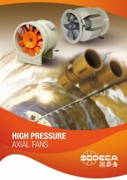
<strong>HTP</strong><strong>HTP</strong>Cased high-pressure axial fansRobust cased axial high-pressure fans, especially designed for mining installationswith large losses of loadFan:• Sheet steel thick long casing• Motor base welded to the casing• Guidelines for high aerodynamic performance for pressure gain• Optimum surface protection by means of high-quality steel.• High-performance, cast aluminium impeller.• Airflow direction from impeller to motor• Electrical connection in outside terminal board.Motor:• Single-phase two-speed motors with IE-2efficiency, except lower powers 0.75 kW.• Class F motors with ball bearings,IP-55 protection• Three-phase 220/380V. 60HZ (up to 5.5CV)and 380/660V. 60Hz.(power over 5.5CV.)• Working temperature: -20ºC +70ºCFinish:• High-protection, anti-corrosion steel,specially primed and high-quality paint forcorrosive environments.On request:• Standardised IP-55 motors, ATEX motorsand two speeds• Stainless steel or iron impellers• Made entirely from stainless steel.• Hot-rolled galvanised steel constructionHigh pressureimpellerOrder code<strong>HTP</strong> 63 2T 10 20º60HzCased high-pressureaxial fansImpellerdiameterin cm.Number ofmotor poles2=3500 r/min. 60 Hz4=1680 r/min. 60 HzT=Three-phasePower motor(C.V.)Angle of inclination ofthe bladesTechnical characteristicsModelSpeed(r/min)Maximum admissiblecurrent (A)220V 380V 660VInstalledpower(kW)Maximumairflow(m 3 /h)Approx.weight(Kg)<strong>HTP</strong>-50-2T-4 3505 10.09 5.80 - 3.00 11000 49 82<strong>HTP</strong>-50-2T-5.5 3505 13.22 7.60 - 4.00 13200 65 83<strong>HTP</strong>-56-2T-5.5 3505 13.22 7.60 - 4.00 16600 69 88<strong>HTP</strong>-56-2T-10 3505 - 14.00 8.12 7.50 22600 147 89<strong>HTP</strong>-63-2T-10 3505 - 14.00 8.12 7.50 19750 132 94<strong>HTP</strong>-63-2T-15 3540 - 19.20 11.13 11.00 24150 167 94<strong>HTP</strong>-63-2T-20 3540 - 26.00 15.07 15.00 30800 181 97<strong>HTP</strong>-63-2T-25 3540 - 31.50 18.26 18.50 35300 199 98<strong>HTP</strong>-63-2T-30 3540 - 39.50 22.90 22.00 37550 208 99<strong>HTP</strong>-63-4T-1.5 1715 4.17 2.40 - 1.10 10850 92 79<strong>HTP</strong>-63-4T-2 1715 5.74 3.30 - 1.50 13200 93 79<strong>HTP</strong>-63-4T-3 1740 8.00 4.60 - 2.20 16550 101 83<strong>HTP</strong>-63-4T-4 1740 10.96 6.30 - 3.00 19700 104 84<strong>HTP</strong>-71-2T-15 3540 - 19.20 11.13 11.00 31750 184 93<strong>HTP</strong>-71-2T-20 3540 - 26.00 15.07 15.00 36850 198 95<strong>HTP</strong>-71-2T-25 3540 - 31.50 18.26 18.50 39400 216 95<strong>HTP</strong>-71-2T-30 3540 - 39.50 22.90 22.00 41950 225 95<strong>HTP</strong>-71-2T-40 3540 - 51.60 29.91 30.00 49600 303 98<strong>HTP</strong>-71-4T-2 1715 5.74 3.30 - 1.50 16550 110 83<strong>HTP</strong>-71-4T-3 1740 8.00 4.60 - 2.20 19700 118 83<strong>HTP</strong>-71-4T-4 1740 10.96 6.30 - 3.00 22250 121 84NPSdB(A)57
<strong>HTP</strong>Technical characteristicsModelSpeed(r/min)Maximum admissiblecurrent (A)220V 380V 660VInstalledpower(kW)Maximumairflow(m 3 /h)Approx.weight(Kg)<strong>HTP</strong>-71-4T-5.5 1740 15.30 8.80 - 4.00 26050 127 87<strong>HTP</strong>-71-4T-7.5 1740 - 11.20 6.49 5.50 30100 141 90<strong>HTP</strong>-80-4T-4 1740 10.96 6.30 - 3.00 16250 146 86<strong>HTP</strong>-80-4T-5.5 1740 15.30 8.80 - 4.00 19750 152 86<strong>HTP</strong>-80-4T-7.5 1740 - 11.20 6.49 5.50 23150 166 86<strong>HTP</strong>-80-4T-10 1740 - 15.30 8.87 7.50 29600 177 87<strong>HTP</strong>-80-4T-15 1740 - 20.90 12.12 11.00 35550 217 91<strong>HTP</strong>-90-4T-7.5 1740 - 11.20 6.49 5.50 25400 196 90<strong>HTP</strong>-90-4T-10 1740 - 15.30 8.87 7.50 29700 207 90<strong>HTP</strong>-90-4T-15 1740 - 20.90 12.12 11.00 35900 247 90<strong>HTP</strong>-90-4T-20 1740 - 28.50 16.52 15.00 45050 266 94<strong>HTP</strong>-90-4T-25 1775 - 34.50 20.00 18.50 47850 294 95<strong>HTP</strong>-90-4T-30 1775 - 40.90 23.71 22.00 53850 311 97<strong>HTP</strong>-100-4T-15 1740 - 20.90 12.12 11.00 40950 282 93<strong>HTP</strong>-100-4T-20 1740 - 28.50 16.52 15.00 50750 301 93<strong>HTP</strong>-100-4T-25 1775 - 34.50 20.00 18.50 55300 329 93<strong>HTP</strong>-100-4T-30 1775 - 40.90 23.71 22.00 59350 346 96<strong>HTP</strong>-100-4T-40 1775 - 55.30 32.06 30.00 71900 401 98<strong>HTP</strong>-125-4T-40 1775 - 55.30 32.06 30.00 69400 503 100<strong>HTP</strong>-125-4T-50 1775 - 68.00 39.42 37.00 79650 525 100<strong>HTP</strong>-125-4T-60 1775 - 81.30 47.13 45.00 89750 558 100<strong>HTP</strong>-125-4T-75 1775 - 98.90 57.33 55.00 97200 599 100<strong>HTP</strong>-125-4T-100 1775 - 135.00 78.26 75.00 126050 674 104<strong>HTP</strong>-125-4T-125 1775 - 163.00 94.49 90.00 144450 703 105NPSdB(A)Acoustic featuresThe specified values are determined according to free field measurements of pressure and sound levels in dB(A) at an equivalent distance oftwice the fan’s span plus the impeller’s diameter, with a minimum of 1.5 m.Model LpdB(A) 63 125 250 500 1000 2000 4000 8000<strong>HTP</strong>-50-2T-4 80 57 77 85 90 92 89 82 71<strong>HTP</strong>-50-2T-5,5 81 58 78 86 91 93 90 83 72<strong>HTP</strong>-56-2T-5,5 86 63 83 91 96 98 95 88 77<strong>HTP</strong>-56-2T-10 87 64 84 92 97 99 96 89 78<strong>HTP</strong>-63-2T-10 94 70 82 92 104 105 104 99 91<strong>HTP</strong>-63-2T-15 94 70 82 92 104 105 104 99 91<strong>HTP</strong>-63-2T-20 97 73 85 95 107 108 107 102 94<strong>HTP</strong>-63-2T-25 98 74 86 96 108 109 108 103 95<strong>HTP</strong>-63-2T-30 99 75 87 97 109 110 109 104 96<strong>HTP</strong>-63-4T-1,5 79 55 67 77 89 90 89 84 76<strong>HTP</strong>-63-4T-2 79 55 67 77 89 90 89 84 76<strong>HTP</strong>-63-4T-3 83 59 71 81 93 94 93 88 80<strong>HTP</strong>-63-4T-4 84 60 72 82 94 95 94 89 81<strong>HTP</strong>-71-2T-15 93 65 83 93 102 104 103 100 93<strong>HTP</strong>-71-2T-20 95 67 85 95 104 106 105 102 95<strong>HTP</strong>-71-2T-25 95 67 85 95 104 106 105 102 95<strong>HTP</strong>-71-2T-30 95 67 85 95 104 106 105 102 95<strong>HTP</strong>-71-2T-40 98 70 88 98 107 109 108 105 98<strong>HTP</strong>-71-4T-2 83 55 73 83 92 93 93 90 83<strong>HTP</strong>-71-4T-3 83 55 72 83 92 93 93 90 83<strong>HTP</strong>-71-4T-4 84 56 74 84 94 95 95 91 85<strong>HTP</strong>-71-4T-5,5 87 59 77 87 97 98 98 95 88<strong>HTP</strong>-71-4T-7,5 90 62 80 90 100 101 101 97 91Dimensions in mmSound power Lw(A) spectrum in dB(A) via frequency band in Hz.Model LpdB(A) 63 125 250 500 1000 2000 4000 8000<strong>HTP</strong>-80-4T-4 86 58 75 86 95 96 96 93 86<strong>HTP</strong>-80-4T-5,5 86 58 76 86 95 96 96 93 86<strong>HTP</strong>-80-4T-7,5 86 58 76 86 95 96 96 93 86<strong>HTP</strong>-80-4T-10 87 59 77 87 97 98 98 94 88<strong>HTP</strong>-80-4T-15 91 63 81 91 101 102 102 99 92<strong>HTP</strong>-90-4T-7,5 90 62 79 90 99 100 100 97 90<strong>HTP</strong>-90-4T-10 90 62 80 90 99 100 100 97 90<strong>HTP</strong>-90-4T-15 90 62 80 90 100 101 101 98 91<strong>HTP</strong>-90-4T-20 94 66 83 94 103 104 104 101 94<strong>HTP</strong>-90-4T-25 95 67 85 95 104 105 105 102 95<strong>HTP</strong>-90-4T-30 97 69 87 97 107 108 108 104 98<strong>HTP</strong>-100-4T-15 93 65 83 93 102 103 103 100 93<strong>HTP</strong>-100-4T-20 93 65 82 93 102 103 103 100 93<strong>HTP</strong>-100-4T-25 93 65 83 93 102 103 103 100 93<strong>HTP</strong>-100-4T-30 96 67 85 96 105 106 106 103 96<strong>HTP</strong>-100-4T-40 98 70 88 98 107 108 108 105 98<strong>HTP</strong>-125-4T-40 100 72 89 100 109 110 110 107 100<strong>HTP</strong>-125-4T-50 100 72 90 100 109 110 110 107 100<strong>HTP</strong>-125-4T-60 100 72 89 100 109 110 110 107 100<strong>HTP</strong>-125-4T-75 100 72 90 100 110 111 111 108 101<strong>HTP</strong>-125-4T-100 104 76 93 104 113 114 114 111 104<strong>HTP</strong>-125-4T-125 105 77 95 105 114 115 115 112 105Model Power ØA ØB ØD E E1 C ØJ N<strong>HTP</strong>-50-2T 600 560 514 - - 500 12 12x30º<strong>HTP</strong>-56-2T 660 620 560 - - 500 12 12x30º<strong>HTP</strong>-63-2T 730 690 640 650 220 870 12 12x30º<strong>HTP</strong>-63-4T 730 690 640 340 220 560 12 12x30º<strong>HTP</strong>-71-2T 810 770 710 700 240 940 12 16x22º30’<strong>HTP</strong>-71-4T 810 770 710 420 240 660 12 16x22º30’<strong>HTP</strong>-80-4T 4 / 5’5 900 860 800 360 240 600 12 16x22º30’<strong>HTP</strong>-80-4T 7’5 / 10 / 15 900 860 800 550 240 790 12 16x22º30’<strong>HTP</strong>-90-4T 7’5 / 10 1015 970 900 420 250 670 15 16x22º30’<strong>HTP</strong>-90-4T 15 / 20 / 25 / 30 1015 970 900 650 250 900 15 16x22º30’<strong>HTP</strong>-100-4T 15 / 20 1115 1070 1000 550 270 820 15 16x22º30’<strong>HTP</strong>-100-4T 25 / 30 / 40 1115 1070 1000 700 270 970 15 16x22º30’<strong>HTP</strong> -125 1360 1311 1258 - - 810 14 20x18º58
<strong>HTP</strong>EXAMPLE OF SELECTIONCharacteristic curvesQ = Airflow in m 3 /h, m 3 /s and cfm.Pe = Static pressure in mm.w.c., Pa and inwg.<strong>HTP</strong>-63-4TInitial data• Working point:• Airflow: 12,500 m 3 /h• Loss of load: 7.5 mm w.c.Absorbed powerRecommended motor power kW (CV)Steps for the selectionof equipmentOn the pressure graph:• 1. Mark the working point,defined by the airflow(12,500 m 3 /h) and the loss ofload (7.5 mm w.c.).• 2. Select the curve of theequipment which is closestabove the working point. In ourcase, a curve with a blade angleof 22º is obtained.On the power graph:• 3. Mark the working point,defined by the airflow(12,500 m3/h) and the selectedblade angle (22º).• 4. Read the absorbed power onthe power axis on the left.Pa= 560 W at the working point.• 5. Look for the straight red linewhich is closest to the workingpoint above. On the right-handside of the graph, the value ofthe installed motor power isobtained. In our case, this is0.75 kW or 1 CV.EXAMPLE OF ORDER CODE<strong>HTP</strong> 63 4T 1 22ºCased high-pressureaxial fansImpellerdiameterin cm.Number of motor poles4=1680 r/min. 60 Hz6=1080 r/min. 60 Hz8=900 r/min. 60 HzT=Three-phaseM=Single-phaseMotor power(C.V.)Angleof inclination ofthe blades59
<strong>HTP</strong>Characteristic curvesQ = Airflow in m 3 /h, m 3 /s and cfm.Pe = Static pressure in mm.w.c., Pa and inwg.<strong>HTP</strong>-50-2TAbsorbed powerRecommendedmotor powerkW (CV)60
<strong>HTP</strong>Characteristic curvesQ = Airflow in m 3 /h, m 3 /s and cfm.Pe = Static pressure in mm.w.c., Pa and inwg.<strong>HTP</strong>-56-2TAbsorbed powerRecommendedmotor powerkW (CV)61
<strong>HTP</strong>Characteristic curvesQ = Airflow in m 3 /h, m 3 /s and cfm.Pe = Static pressure in mm.w.c., Pa and inwg.<strong>HTP</strong>-63-2TAbsorbed powerRecommendedmotor powerkW (CV)62
<strong>HTP</strong>Characteristic curvesQ = Airflow in m 3 /h, m 3 /s and cfm.Pe = Static pressure in mm.w.c., Pa and inwg.<strong>HTP</strong>-63-4TAbsorbed powerRecommendedmotor powerkW (CV)63
<strong>HTP</strong>Characteristic curvesQ = Airflow in m 3 /h, m 3 /s and cfm.Pe = Static pressure in mm.w.c., Pa and inwg.<strong>HTP</strong>-71-2TAbsorbed powerRecommendedmotor powerkW (CV)64
<strong>HTP</strong>Characteristic curvesQ = Airflow in m 3 /h, m 3 /s and cfm.Pe = Static pressure in mm.w.c., Pa and inwg.<strong>HTP</strong>-71-4TAbsorbed powerRecommendedmotor powerkW (CV)65
<strong>HTP</strong>Characteristic curvesQ = Airflow in m 3 /h, m 3 /s and cfm.Pe = Static pressure in mm.w.c., Pa and inwg.<strong>HTP</strong>-80-4TAbsorbed powerRecommendedmotor powerkW (CV)66
<strong>HTP</strong>Characteristic curvesQ = Airflow in m 3 /h, m 3 /s and cfm.Pe = Static pressure in mm.w.c., Pa and inwg.<strong>HTP</strong>-90-4TAbsorbed powerRecommendedmotor powerkW (CV)67
<strong>HTP</strong>Characteristic curvesQ = Airflow in m 3 /h, m 3 /s and cfm.Pe = Static pressure in mm.w.c., Pa and inwg.<strong>HTP</strong>-100-4TAbsorbed powerRecommendedmotor powerkW (CV)68
<strong>HTP</strong>Characteristic curvesQ = Airflow in m 3 /h, m 3 /s and cfm.Pe = Static pressure in mm.w.c., Pa and inwg.<strong>HTP</strong>-125-4TAbsorbed powerRecommendedmotor powerkW (CV)AccessoriesSee accessories section.INT AR RFT/ RFM PANELS PL P RT BTUB BAC PS S SI69
HGTHGTXHGTHGTXHGT: Large long cased axial fans with direct drive motorHGTX: Large long cased axial fans with external motorLong cased axial fans, supplied with 3, 6 or 9 blade aluminium impellers withdifferent slope angles.Fan:• Airflow direction from motor to impeller• Variable angle impellers in cast aluminium (HGTX: of 3, 6 or 9 blades with differentslope angles).• Sheet steel long casing• HGT: The long-casing version is equipped with an inspection hatch• HGTX: Equipped with inspection hatchHGTHGTXMotor:• Single-phase two-speed motors withIE-2 efficiency, except lower powers0.75 kW.• Class F motors with ball bearings,IP55 protection• Three-phase 220/380V. 60HZ(up to 5.5CV) and 380/660V. 60Hz.(power over 5.5CV.)• Working temperature:-25ºC.+ 50ºC (HGT),-25ºC.+ 120ºC (HGTX)Finish:• Anticorrosive finish in polyester resin,polymerised at 190ºC, after alkalinedegreasing and phosphate-freepre-treatment.On request:• Airflow direction from impeller tomotor.• 100% reversible impellers• Special windings for differentvoltages.• ATEX certification, Category 2Order codeHGT 125 4T 6-2060HzHGT: Large long cased axialfans with direct drive motorHGTX: Large long casedaxial fans with external motorImpellerdiameterin cm.Number of motor poles4=1680 r/min. 60 Hz6=1080 r/min. 60 Hz8=900 r/min. 60 HzT=Three-phaseM=Single-phaseNumberof blades3 blades6 blades9 bladesMotor power(C.V.)Technical characteristicsModelSpeed(r/min)Maximum admissiblecurrent (A)220V 380V 660VInstalledPower(kW)Maximumairflow(m 3 /h)Soundpressure leveldB(A)Approx. weight(Kg)HGT HGTXHGT-125-4T/3-10 HGTX-125-4T/3-10 1740 14.80 8.54 7.50 54400 88 Long 211 Short 178 342HGT-125-4T/3-15 HGTX-125-4T/3-15 1750 21.50 12.40 11.00 62050 89 249 221 369HGT-125-4T/3-20 HGTX-125-4T/3-20 1745 28.50 16.50 15.00 69800 91 268 240 388HGT-125-4T/3-25 HGTX-125-4T/3-25 1765 35.00 20.20 18.50 85200 91 331 288 418HGT-125-4T/3-30 HGTX-125-4T/3-30 1765 41.00 23.70 22.00 92950 92 348 305 435HGT-125-4T/3-40 HGTX-125-4T/3-40 1770 56.00 32.30 30.00 118000 93 440 397 529HGT-125-4T/3-50 HGTX-125-4T/3-50 1775 68.00 39.30 37.00 125300 94 474 418 545HGT-125-4T/3-60 HGTX-125-4T/3-60 1775 84.00 48.50 45.00 139900 95 489 433 560HGT-125-4T/6-20 HGTX-125-4T/6-20 1745 28.50 16.50 15.00 77450 89 277 249 397HGT-125-4T/6-25 HGTX-125-4T/6-25 1765 35.00 20.20 18.50 81550 90 340 297 427HGT-125-4T/6-30 HGTX-125-4T/6-30 1765 41.00 23.70 22.00 85750 90 357 314 444HGT-125-4T/6-40 HGTX-125-4T/6-40 1770 56.00 32.30 30.00 102200 92 449 405 538HGT-125-4T/6-50 HGTX-125-4T/6-50 1775 68.00 39.30 37.00 117700 93 483 427 554HGT-125-4T/6-60 HGTX-125-4T/6-60 1775 84.00 48.50 45.00 125000 94 498 442 569HGT-125-4T/6-75 HGTX-125-4T/6-75 1775 98.00 56.60 55.00 140350 95 549 499 635HGT-125-4T/6-100 HGTX-125-4T/6-100 1775 132.00 76.20 75.00 156500 96 598 548 684HGT-125-4T/9-25 HGTX-125-4T/9-25 1765 35.00 20.20 18.50 75150 88 349 306 436HGT-125-4T/9-30 HGTX-125-4T/9-30 1765 41.00 23.70 22.00 80250 89 366 323 45370
HGTHGTXTechnical characteristicsModelSpeed Maximum admissible Installed Maximum Sound Approx. weightcurrent (A)Power airflow pressure level(Kg)(r/min) 220V 380V 660V (kW) (m 3 /h) dB(A) HGT HGTXHGT-125-4T/9-40 HGTX-125-4T/9-40 1770 56.00 32.30 30.00 85350 91 Long 458 Short 414 547HGT-125-4T/9-50 HGTX-125-4T/9-50 1775 68.00 39.30 37.00 106050 93 492 436 563HGT-125-4T/9-60 HGTX-125-4T/9-60 1775 84.00 48.50 45.00 116400 94 507 451 578HGT-125-4T/9-75 HGTX-125-4T/9-75 1775 98.00 56.60 55.00 124950 95 558 508 644HGT-125-4T/9-100 HGTX-125-4T/9-100 1775 132.00 76.20 75.00 152050 99 607 557 693HGT-125-6T/3-4 HGTX-125-6T/3-4 1120 12.10 7.00 3.00 40700 79 204 171 335HGT-125-6T/3-5.5 HGTX-125-6T/3-5.5 1130 15.50 8.95 4.00 45750 80 209 176 340HGT-125-6T/3-7.5 HGTX-125-6T/3-7.5 1145 11.90 6.87 5.50 55850 81 217 184 348HGT-125-6T/3-10 HGTX-125-6T/3-10 1165 15.40 8.89 7.50 66350 83 262 234 382HGT-125-6T/3-15 HGTX-125-6T/3-15 1165 23.00 13.30 11.00 86900 84 276 248 396HGT-125-6T/3-20 HGTX-125-6T/3-20 1165 31.00 17.90 15.00 98350 85 358 315 445HGT-125-6T/6-5.5 HGTX-125-6T/6-5.5 1130 15.50 8.95 4.00 48500 77 218 185 349HGT-125-6T/6-7.5 HGTX-125-6T/6-7.5 1145 11.90 6.87 5.50 53650 77 226 193 357HGT-125-6T/6-10 HGTX-125-6T/6-10 1165 15.40 8.89 7.50 61550 79 271 243 391HGT-125-6T/6-15 HGTX-125-6T/6-15 1165 23.00 13.30 11.00 77100 81 285 257 405HGT-125-6T/6-20 HGTX-125-6T/6-20 1165 31.00 17.90 15.00 91950 82 367 324 454HGT-125-6T/6-25 HGTX-125-6T/6-25 1180 36.00 20.80 18.50 97250 84 409 365 498HGT-125-6T/9-10 HGTX-125-6T/9-10 1165 15.40 8.89 7.50 55900 78 280 252 400HGT-125-6T/9-15 HGTX-125-6T/9-15 1165 23.00 13.30 11.00 69500 81 294 266 414HGT-125-6T/9-20 HGTX-125-6T/9-20 1165 31.00 17.90 15.00 81850 84 376 333 463HGT-125-6T/9-25 HGTX-125-6T/9-25 1180 36.00 20.80 18.50 93050 85 418 374 507HGT-125-6T/9-30 HGTX-125-6T/9-30 1175 43.00 24.80 22.00 99650 87 438 394 527HGT-125-8T/3-3 HGTX-125-8T/3-3 865 10.20 5.90 2.20 42100 71 209 176 340HGT-125-8T/3-4 HGTX-125-8T/3-4 865 13.50 7.80 3.00 50050 71 216 183 347HGT-125-8T/3-5.5 HGTX-125-8T/3-5.5 860 17.30 10.00 4.00 58350 73 249 221 369HGT-125-8T/3-7.5 HGTX-125-8T/3-7.5 850 13.40 7.74 5.50 69150 75 262 234 382HGT-125-8T/6-3 HGTX-125-8T/6-3 865 10.20 5.90 2.20 40250 69 218 185 349HGT-125-8T/6-4 HGTX-125-8T/6-4 865 13.50 7.80 3.00 46450 71 225 192 356HGT-125-8T/6-5.5 HGTX-125-8T/6-5.5 860 17.30 10.00 4.00 54600 72 258 230 378HGT-125-8T/6-7.5 HGTX-125-8T/6-7.5 850 13.40 7.74 5.50 61800 73 271 243 391HGT-125-8T/6-10 HGTX-125-8T/6-10 860 18.10 10.45 7.50 73350 75 301 273 421HGT-125-8T/9-4 HGTX-125-8T/9-4 865 13.50 7.80 3.00 39450 70 234 201 365HGT-125-8T/9-5.5 HGTX-125-8T/9-5.5 860 17.30 10.00 4.00 47300 73 267 239 387HGT-125-8T/9-7.5 HGTX-125-8T/9-7.5 850 13.40 7.74 5.50 57550 75 280 252 400HGT-125-8T/9-10 HGTX-125-8T/9-10 860 18.10 10.45 7.50 65950 76 310 282 430HGT-125-8T/9-15 HGTX-125-8T/9-15 865 23.50 13.60 11.00 84100 79 372 329 459HGT-140-6T/3-4 1150 12.00 6.90 3.00 46500 82 251 214HGT-140-6T/3-5.5 1150 15.10 8.70 4.00 52350 83 258 221HGT-140-6T/3-7.5 1145 11.90 6.90 5.50 58400 84 266 229HGT-140-6T/3-10 1165 15.40 8.90 7.50 67950 85 320 281HGT-140-6T/3-15 1165 23.00 13.30 11.00 81450 86 334 295HGT-140-6T/3-20 1165 31.00 17.90 15.00 103450 88 414 364HGT-140-6T/6-5.5 1150 15.10 8.70 4.00 57200 82 268 231HGT-140-6T/6-7.5 1145 11.90 6.90 5.50 64300 84 276 239HGT-140-6T/6-10 1165 15.40 8.90 7.50 71500 85 330 291HGT-140-6T/6-15 1165 23.00 13.30 11.00 75150 86 344 305HGT-140-6T/6-20 1165 31.00 17.90 15.00 89600 87 423 374HGT-140-6T/6-25 1180 36.00 20.80 18.50 103200 88 466 417HGT-140-6T/6-30 1175 43.00 24.80 22.00 109600 89 486 437HGT-140-6T/9-10 1165 15.40 8.90 7.50 65850 84 339 300HGT-140-6T/9-15 1165 23.00 13.30 11.00 70350 86 353 314HGT-140-6T/9-20 1165 31.00 17.90 15.00 74850 87 433 383HGT-140-6T/9-25 1180 36.00 20.80 18.50 92950 88 475 427HGT-140-6T/9-30 1175 43.00 24.80 22.00 102050 89 495 447HGT-140-6T/9-40 1180 56.00 32.30 30.00 117000 91 561 499HGT-140-6T/9-50 1180 69.00 39.80 37.00 133300 92 623 568HGT-140-8T/3-3 865 10.20 5.90 2.20 41100 78 258 221HGT-140-8T/3-4 865 13.50 7.80 3.00 46150 78 265 228HGT-140-8T/3-5.5 860 17.30 10.00 4.00 56350 79 307 268HGT-140-8T/3-7.5 850 13.40 7.70 5.50 67000 81 320 281HGT-140-8T/3-10 860 18.10 10.50 7.50 82850 82 350 311HGT-140-8T/6-3 865 10.20 5.90 2.20 45650 78 268 231HGT-140-8T/6-4 865 13.50 7.80 3.00 51250 79 275 23871
HGTHGTXTechnical characteristicsModelSpeed(r/min)Maximum admissiblecurrent (A)220V 380V 660VInstalledPower(kW)Maximumairflow(m 3 /h)Soundpressure leveldB(A)Approx. weight(Kg)HGT HGTXHGT-140-8T/6-5.5 860 17.30 10.00 4.00 56700 80 Long 317 Short 278HGT-140-8T/6-7.5 850 13.40 7.70 5.50 62150 81 330 291HGT-140-8T/6-10 860 18.10 10.50 7.50 73050 82 360 321HGT-140-8T/6-15 865 23.50 13.60 11.00 87500 83 419 370HGT-140-8T/9-4 865 13.50 7.80 3.00 42900 79 284 247HGT-140-8T/9-5.5 860 17.30 10.00 4.00 49600 79 326 287HGT-140-8T/9-7.5 850 13.40 7.70 5.50 56450 81 339 300HGT-140-8T/9-10 860 18.10 10.50 7.50 63300 82 369 330HGT-140-8T/9-15 865 23.50 13.60 11.00 82600 83 429 379HGT-140-8T/9-20 890 29.00 16.70 15.00 93900 86 485 437HGT-160-6T/3-5.5 1150 15.10 8.70 4.00 61100 81 327 275HGT-160-6T/3-7.5 1145 11.90 6.90 5.50 71150 82 335 283HGT-160-6T/3-10 1165 15.40 8.90 7.50 76200 83 393 339HGT-160-6T/3-15 1165 23.00 13.30 11.00 81250 85 407 353HGT-160-6T/3-20 1165 31.00 17.90 15.00 101450 86 500 431HGT-160-6T/3-25 1180 36.00 20.80 18.50 111500 87 543 473HGT-160-6T/3-30 1175 43.00 24.80 22.00 121600 89 563 493HGT-160-6T/6-10 1165 15.40 8.90 7.50 71500 83 404 350HGT-160-6T/6-15 1165 23.00 13.30 11.00 89400 85 418 364HGT-160-6T/6-20 1165 31.00 17.90 15.00 100950 86 510 441HGT-160-6T/6-25 1180 36.00 20.80 18.50 106600 87 553 484HGT-160-6T/6-30 1175 43.00 24.80 22.00 112200 88 573 504HGT-160-6T/6-40 1180 56.00 32.30 30.00 133700 89 656 557HGT-160-6T/6-50 1180 69.00 39.80 37.00 154050 91 714 629HGT-160-6T/9-15 1165 23.00 13.30 11.00 84600 85 428 374HGT-160-6T/9-20 1165 31.00 17.90 15.00 91550 86 520 451HGT-160-6T/9-25 1180 36.00 20.80 18.50 98300 87 563 494HGT-160-6T/9-30 1175 43.00 24.80 22.00 105050 88 583 514HGT-160-6T/9-40 1180 56.00 32.30 30.00 111700 89 666 567HGT-160-6T/9-50 1180 69.00 39.80 37.00 138750 90 724 640HGT-160-6T/9-60 1180 92.00 53.10 45.00 152300 91 844 745HGT-160-6T/9-75 1190 102.00 58.90 55.00 163500 92 932 833HGT-160-6T/9-100 1190 139.00 80.30 75.00 199000 93 1002 903HGT-160-8T/3-3 865 10.20 5.90 2.20 50800 76 327 275HGT-160-8T/3-4 865 13.50 7.80 3.00 54350 77 334 282HGT-160-8T/3-5.5 860 17.30 10.00 4.00 65200 79 380 326HGT-160-8T/3-7.5 850 13.40 7.70 5.50 68900 80 393 339HGT-160-8T/3-10 860 18.10 10.50 7.50 84150 81 423 369HGT-160-8T/3-15 865 23.50 13.60 11.00 100000 83 496 427HGT-160-8T/6-4 865 13.50 7.80 3.00 63750 76 344 292HGT-160-8T/6-5.5 860 17.30 10.00 4.00 72350 77 391 337HGT-160-8T/6-7.5 850 13.40 7.70 5.50 76500 79 404 350HGT-160-8T/6-10 860 18.10 10.50 7.50 84650 80 434 380HGT-160-8T/6-15 865 23.50 13.60 11.00 92750 82 506 437HGT-160-8T/6-20 890 29.00 16.70 15.00 109000 83 563 494HGT-160-8T/6-25 875 37.00 21.40 18.50 123400 84 641 542HGT-160-8T/9-7.5 850 13.40 7.70 5.50 63150 79 414 360HGT-160-8T/9-10 860 18.10 10.50 75.00 79200 80 444 390HGT-160-8T/9-15 865 23.50 13.60 11.00 84250 82 516 447HGT-160-8T/9-20 890 29.00 16.70 15.00 94500 83 573 504HGT-160-8T/9-25 875 37.00 21.40 18.50 114900 84 651 552HGT-160-8T/9-30 875 45.00 26.00 22.00 123350 85 666 567HGT-160-8T/9-40 880 59.00 34.10 30.00 140200 86 724 64072
HGTHGTXAcoustic featuresThe specified values are determined according to free field measurements of pressure and sound levels in dB(A) at an equivalent distance oftwice the fan’s span plus the impeller’s diameter, with a minimum of 1.5 m.Sound power Lw(A) spectrum in dB(A) via frequency band in Hz.Model 63 125 250 500 1000 2000 4000 8000125-4T/3-10 70 76 88 98 98 94 86 82125-4T/3-15 71 77 89 99 99 95 87 83125-4T/3-20 72 78 90 100 100 96 88 84125-4T/3-25 73 79 91 101 101 97 89 85125-4T/3-30 74 80 92 102 102 98 90 86125-4T/3-40 75 81 93 103 103 99 91 87125-4T/3-50 76 82 94 104 104 100 92 88125-4T/3-60 77 83 95 105 105 101 93 89125-4T/6-20 66 74 90 97 99 94 88 84125-4T/6-25 67 75 91 98 100 95 89 85125-4T/6-30 68 76 92 99 101 96 90 86125-4T/6-40 69 77 93 100 102 97 91 87125-4T/6-50 71 79 95 102 104 99 93 89125-4T/6-60 72 80 96 103 105 100 94 90125-4T/6-75 72 80 96 103 105 100 94 90125-4T/6-100 74 82 98 105 107 102 96 92125-4T/9-25 66 74 91 97 98 93 88 84125-4T/9-30 67 75 92 98 99 94 89 85125-4T/9-40 68 76 93 99 100 95 90 86125-4T/9-50 70 78 95 101 102 97 92 88125-4T/9-60 72 80 97 103 104 99 94 90125-4T/9-75 72 80 97 103 104 99 94 90125-4T/9-100 74 82 99 105 106 101 96 92125-6T/3-4 64 72 84 88 86 81 72 68125-6T/3-5,5 66 74 86 90 88 83 74 70125-6T/3-7,5 67 75 87 91 89 84 75 71125-6T/3-10 68 76 88 92 90 85 76 72125-6T/3-15 69 77 89 93 91 86 77 73125-6T/3-20 71 79 91 95 93 88 79 75125-6T/6-5,5 59 68 81 84 85 82 71 67125-6T/6-7,5 60 69 82 85 86 83 72 68125-6T/6-10 61 70 83 86 87 84 73 69125-6T/6-15 63 72 85 88 89 86 75 71125-6T/6-20 65 74 87 90 91 88 77 73125-6T/6-25 66 75 88 91 92 89 78 74125-6T/9-10 57 67 82 86 85 84 73 69125-6T/9-15 59 69 84 88 87 86 75 71125-6T/9-20 62 72 87 91 90 89 78 74125-6T/9-25 64 74 89 93 92 91 80 76125-6T/9-30 66 76 91 95 94 93 82 78125-8T/3-3 56 63 74 78 77 70 61 57125-8T/3-4 59 66 77 81 80 73 64 60125-8T/3-5,5 60 67 78 82 81 74 65 61125-8T/3-7,5 62 69 80 84 83 76 67 63125-8T/6-3 53 61 73 78 77 72 61 57125-8T/6-4 54 62 74 79 78 73 62 58125-8T/6-5,5 56 64 76 81 80 75 64 60125-8T/6-7,5 58 66 78 83 82 77 66 62125-8T/6-10 59 67 79 84 83 78 67 63125-8T/9-4 51 62 72 78 79 74 63 59125-8T/9-5,5 53 64 74 80 81 76 65 61125-8T/9-7,5 56 67 77 83 84 79 68 64125-8T/9-10 58 69 79 85 86 81 70 66125-8T/9-15 59 70 80 86 87 82 71 67140-6T/3-4 66 76 84 89 88 87 74 74140-6T/3-5,5 69 79 87 92 91 90 77 77140-6T/3-7,5 69 79 87 92 91 90 77 77140-6T/3-10 70 80 88 93 92 91 78 78140-6T/3-15 71 81 89 94 93 92 79 79140-6T/3-20 73 83 91 96 95 94 81 81140-6T/6-5,5 66 81 90 92 89 83 75 71140-6T/6-7,5 67 82 91 93 90 84 76 72140-6T/6-10 68 83 92 94 91 85 77 73140-6T/6-15 69 84 93 95 92 86 78 74140-6T/6-20 71 86 95 97 94 88 80 76140-6T/6-25 72 87 96 98 95 89 81 77140-6T/6-30 73 88 97 99 96 90 82 78Model 63 125 250 500 1000 2000 4000 8000140-6T/9-10 66 84 93 92 91 87 78 73140-6T/9-15 67 85 94 93 92 88 79 74140-6T/9-20 69 87 96 95 94 90 81 76140-6T/9-25 70 88 97 96 95 91 82 77140-6T/9-30 70 88 97 96 95 91 82 77140-6T/9-40 71 89 98 97 96 92 83 78140-6T/9-50 74 92 101 100 99 95 86 81140-8T/3-3 60 70 78 83 82 81 68 63140-8T/3-4 64 74 82 87 86 85 72 67140-8T/3-5,5 65 75 83 88 87 86 73 68140-8T/3-7,5 66 76 84 89 88 87 74 69140-8T/3-10 68 78 86 91 90 89 76 71140-8T/6-3 61 73 82 86 84 78 68 65140-8T/6-4 63 75 84 88 86 80 70 67140-8T/6-5,5 64 76 85 89 87 81 71 68140-8T/6-7,5 65 77 86 90 88 82 72 69140-8T/6-10 66 78 87 91 89 83 73 70140-8T/6-15 68 80 89 93 91 85 75 72140-8T/9-4 61 72 83 88 86 82 72 67140-8T/9-5,5 62 73 84 89 87 83 73 68140-8T/9-7,5 63 74 85 90 88 84 74 69140-8T/9-10 64 75 86 91 89 85 75 70140-8T/9-15 65 76 87 92 90 86 76 71140-8T/9-20 67 78 89 94 92 88 78 73160-6T/3-5,5 67 77 85 90 89 88 75 70160-6T/3-7,5 68 78 86 91 90 89 76 71160-6T/3-10 69 79 87 92 91 90 77 72160-6T/3-15 70 80 88 93 92 91 78 73160-6T/3-20 72 82 90 95 94 93 80 75160-6T/3-25 73 83 91 96 95 94 81 76160-6T/3-30 74 84 92 97 96 95 82 77160-6T/6-10 67 82 91 93 90 84 76 72160-6T/6-15 68 83 92 94 91 85 77 73160-6T/6-20 70 85 94 96 93 87 79 75160-6T/6-25 71 86 95 97 94 88 80 76160-6T/6-30 71 86 95 97 94 88 80 76160-6T/6-40 72 87 96 98 95 89 81 77160-6T/6-50 74 89 98 100 97 91 83 79160-6T/9-15 67 85 94 93 92 88 79 74160-6T/9-20 68 86 95 94 93 89 80 75160-6T/9-25 69 87 96 95 94 90 81 76160-6T/9-30 70 88 97 96 95 91 82 77160-6T/9-40 71 89 98 97 96 92 83 78160-6T/9-50 72 90 99 98 97 93 84 79160-6T/9-60 72 90 99 98 97 93 84 79160-6T/9-75 73 91 100 99 98 94 85 80160-6T/9-100 75 93 102 101 100 96 87 82160-8T/3-3 61 71 79 84 83 82 69 64160-8T/3-4 63 73 81 86 85 84 71 66160-8T/3-5,5 64 74 82 87 86 85 72 67160-8T/3-7,5 65 75 83 88 87 86 73 68160-8T/3-10 66 76 84 89 88 87 74 69160-8T/3-15 68 78 86 91 90 89 76 71160-8T/6-4 60 75 84 86 83 77 69 65160-8T/6-5,5 61 76 85 87 84 78 70 66160-8T/6-7,5 62 77 86 88 85 79 71 67160-8T/6-10 63 78 87 89 86 80 72 68160-8T/6-15 65 80 89 91 88 82 74 70160-8T/6-20 66 81 90 92 89 83 75 71160-8T/6-25 68 83 92 94 91 85 77 73160-8T/9-7,5 60 78 87 86 85 81 72 67160-8T/9-10 62 80 89 88 87 83 74 69160-8T/9-15 63 81 90 89 88 84 75 70160-8T/9-20 64 82 91 90 89 85 76 71160-8T/9-25 65 83 92 91 90 86 77 72160-8T/9-30 66 84 93 92 91 87 78 73160-8T/9-40 68 86 95 94 93 89 80 7573
HGTHGTXDimensions in mmHGTØA ØB C (Consult motor build sizes) ØD E ØJ NModel 132 160 180 200 225 250 280 long shortHGT-125 1365 1320 570 - - - - - - 1250 700 500 15 20x18ºHGT-125 1365 1320 - 700 - - - - - 1250 700 500 15 20x18ºHGT-125 1365 1320 - - 765 825 - - - 1250 900 500 15 20x18ºHGT-125 1365 1320 - - - - 910 - - 1250 1000 500 15 20x18ºHGT-125 1365 1320 - - - - - 985 - 1250 1000 600 15 20x18ºHGT-125 1365 1320 - - - - - - 1190 1250 1200 700 15 20x18ºHGT-140 1515 1470 570 - - - - - - 1400 650 400 15 20x18ºHGT-140 1515 1470 - 700 - - - - - 1400 700 450 15 20x18ºHGT-140 1515 1470 - - 765 825 - - - 1400 900 550 15 20x18ºHGT-140 1515 1470 - - - - 910 - - 1400 1000 550 15 20x18ºHGT-140 1515 1470 - - - - - 985 - 1400 1000 600 15 20x18ºHGT-160 1735 1680 570 - - - - - - 1600 650 400 19 24x15ºHGT-160 1735 1680 - 700 - - - - - 1600 700 450 19 24x15ºHGT-160 1735 1680 - - 765 825 - - - 1600 900 550 19 24x15ºHGT-160 1735 1680 - - - - 910 - - 1600 1000 550 19 24x15ºHGT-160 1735 1680 - - - - - 985 - 1600 1000 600 19 24x15ºHGT-160 1735 1680 - - - - - - 1190 1600 1200 700 19 24x15ºMotor build sizes depending on powerPoles r/min C.V. 3 4 5,5 7,5 10 15 20 25 30 40 50 60 75 1004T 1800 - - - - 132 160 160 180 180 200 225 225 250 2806T 1200 - 132 132 132 160 160 180 200 200 225 250 280 280 2808T 900 132 132 160 160 160 180 200 225 225 250 - - - -HGTXØA ØB ØD E H (Consult motor build sizes) ØJ NModel 132 160 180 200 225 250 280HGT-X 125 1365 1320 1250 900 1743 1815 1850 - - - - 15 20x18ºHGT-X 125 1365 1320 1250 960 - - - 1930 1995 - - 15 20x18ºHGT-X 125 1365 1320 1250 1100 - - - - - 2060 - 15 20x18ºHGT-X 125 1365 1320 1250 1100 - - - - - - 2090 15 20x18ºMotor build sizes depending on powerPoles r/min C.V. 3 4 5,5 7,5 10 15 20 25 30 40 50 60 75 1004T 1800 - - - - 132 160 160 180 180 200 225 225 250 2806T 1200 - 132 132 132 160 160 180 200 200 225 250 280 280 2808T 900 132 132 160 160 160 180 200 225 225 250 - - - -74
HGTHGTXEXAMPLE OF SELECTIONCharacteristic curvesQ = Airflow in m 3 /h, m 3 /s and cfm.Pe = Static pressure in mm.w.c., Pa and inwg.Impeller diameter (cm): 125 Number of poles: 8 Number of blades: 3Initial data• Working point:• Airflow: 12,500 m 3 /h• Loss of load: 7.5 mm w.c.Steps for the selectionof equipmentOn the pressure graph:• 1. Mark the working point,defined by the airflow(12,500 m 3 /h) and the loss ofload (7.5 mm w.c.).• 2. Select the curve of theequipment which is closestabove the working point. In ourcase, a curve with a blade angleof 22º is obtained.Absorbed powerRecommended motor power kW (CV)On the power graph:• 3. Mark the working point,defined by the airflow(12,500 m 3 /h) and the selectedblade angle (22º).• 4. Read the absorbed power onthe power axis on the left.Pa= 560 W at the working point.• 5. Look for the straight red linewhich is closest to the workingpoint above. On the right-handside of the graph, the value ofthe installed motor power isobtained. In our case, this is0.75 kW or 1 CV.EXAMPLE OF ORDER CODEHGT 125 8T 3 1 22HGT: Large long cased axialfans with direct drive motorHGTX: Large long cased axialfans with external motorImpellerdiameterin cm.Number of motor poles4=1680 r/min. 60 Hz6=1080 r/min. 60 Hz8=900 r/min. 60 HzT=Three-phaseM=Single-phaseNumberof blades3 blades6 blades9 bladesMotor power(C.V.)Angleof inclinationof theblades75
HGTHGTXCharacteristic curvesQ = Airflow in m 3 /h, m 3 /s and cfm.Pe = Static pressure in mm.w.c., Pa and inwg.Impeller diameter (cm): 125 Number of poles: 4 Number of blades: 3Absorbed powerRecommendedmotor powerkW (CV)76
HGTHGTXCharacteristic curvesQ = Airflow in m 3 /h, m 3 /s and cfm.Pe = Static pressure in mm.w.c., Pa and inwg.Impeller diameter (cm): 125 Number of poles: 4 Number of blades: 6Absorbed powerRecommendedmotor powerkW (CV)77
HGTHGTXCharacteristic curvesQ = Airflow in m 3 /h, m 3 /s and cfm.Pe = Static pressure in mm.w.c., Pa and inwg.Impeller diameter (cm): 125 Number of poles: 4 Number of blades: 9Absorbed powerRecommendedmotor powerkW (CV)78
HGTHGTXCharacteristic curvesQ = Airflow in m 3 /h, m 3 /s and cfm.Pe = Static pressure in mm.w.c., Pa and inwg.Impeller diameter (cm): 125 Number of poles: 6 Number of blades: 3Absorbed powerRecommendedmotor powerkW (CV)79
HGTHGTXCharacteristic curvesQ = Airflow in m 3 /h, m 3 /s and cfm.Pe = Static pressure in mm.w.c., Pa and inwg.Impeller diameter (cm): 125 Number of poles: 6 Number of blades: 6Absorbed powerRecommendedmotor powerkW (CV)80
HGTHGTXCharacteristic curvesQ = Airflow in m 3 /h, m 3 /s and cfm.Pe = Static pressure in mm.w.c., Pa and inwg.Impeller diameter (cm): 125 Number of poles: 6 Number of blades: 9Absorbed powerRecommendedmotor powerkW (CV)81
HGTHGTXCharacteristic curvesQ = Airflow in m 3 /h, m 3 /s and cfm.Pe = Static pressure in mm.w.c., Pa and inwg.Impeller diameter (cm): 125 Number of poles: 8 Number of blades: 3Absorbed powerRecommendedmotor powerkW (CV)82
HGTHGTXCharacteristic curvesQ = Airflow in m 3 /h, m 3 /s and cfm.Pe = Static pressure in mm.w.c., Pa and inwg.Impeller diameter (cm): 125 Number of poles: 8 Number of blades: 6Absorbed powerRecommendedmotor powerkW (CV)83
HGTHGTXCharacteristic curvesQ = Airflow in m 3 /h, m 3 /s and cfm.Pe = Static pressure in mm.w.c., Pa and inwg.Impeller diameter (cm): 125 Number of poles: 8 Number of blades: 9Absorbed powerRecommendedmotor powerkW (CV)84
HGTHGTXCharacteristic curvesQ = Airflow in m 3 /h, m 3 /s and cfm.Pe = Static pressure in mm.w.c., Pa and inwg.Impeller diameter (cm): 140 Number of poles: 6 Number of blades: 3Absorbed powerRecommendedmotor powerkW (CV)85
HGTHGTXCharacteristic curvesQ = Airflow in m 3 /h, m 3 /s and cfm.Pe = Static pressure in mm.w.c., Pa and inwg.Impeller diameter (cm): 140 Number of poles: 6 Number of blades: 6Absorbed powerRecommendedmotor powerkW (CV)86
HGTHGTXCharacteristic curvesQ = Airflow in m 3 /h, m 3 /s and cfm.Pe = Static pressure in mm.w.c., Pa and inwg.Impeller diameter (cm): 140 Number of poles: 6 Number of blades: 9Absorbed powerRecommendedmotor powerkW (CV)87
HGTHGTXCharacteristic curvesQ = Airflow in m 3 /h, m 3 /s and cfm.Pe = Static pressure in mm.w.c., Pa and inwg.Impeller diameter (cm): 140 Number of poles: 8 Number of blades: 3Absorbed powerRecommendedmotor powerkW (CV)88
HGTHGTXCharacteristic curvesQ = Airflow in m 3 /h, m 3 /s and cfm.Pe = Static pressure in mm.w.c., Pa and inwg.Impeller diameter (cm): 140 Number of poles: 8 Number of blades: 6Absorbed powerRecommendedmotor powerkW (CV)89
HGTHGTXCharacteristic curvesQ = Airflow in m 3 /h, m 3 /s and cfm.Pe = Static pressure in mm.w.c., Pa and inwg.Impeller diameter (cm): 140 Number of poles: 8 Number of blades: 9Absorbed powerRecommendedmotor powerkW (CV)90
HGTHGTXCharacteristic curvesQ = Airflow in m 3 /h, m 3 /s and cfm.Pe = Static pressure in mm.w.c., Pa and inwg.Impeller diameter (cm): 160 Number of poles: 6 Number of blades: 3Absorbed powerRecommendedmotor powerkW (CV)91
HGTHGTXCharacteristic curvesQ = Airflow in m 3 /h, m 3 /s and cfm.Pe = Static pressure in mm.w.c., Pa and inwg.Impeller diameter (cm): 160 Number of poles: 6 Number of blades: 6Absorbed powerRecommendedmotor powerkW (CV)92
HGTHGTXCharacteristic curvesQ = Airflow in m 3 /h, m 3 /s and cfm.Pe = Static pressure in mm.w.c., Pa and inwg.Impeller diameter (cm): 160 Number of poles: 6 Number of blades: 9Absorbed powerRecommendedmotor powerkW (CV)93
HGTHGTXCharacteristic curvesQ = Airflow in m 3 /h, m 3 /s and cfm.Pe = Static pressure in mm.w.c., Pa and inwg.Impeller diameter (cm): 160 Number of poles: 8 Number of blades: 3Absorbed powerRecommendedmotor powerkW (CV)94
HGTHGTXCharacteristic curvesQ = Airflow in m 3 /h, m 3 /s and cfm.Pe = Static pressure in mm.w.c., Pa and inwg.Impeller diameter (cm): 160 Number of poles: 8 Number of blades: 9Absorbed powerRecommendedmotor powerkW (CV)AccessoriesSee accessories section.INT AR RFT/ RFM PANELS RT BTUB BAC PS S SI96
KITS DE SOBREPRESIÓNKIT SOBREPRESIÓNThe system of pressurisation of staircases, escape routes or of confinement makes it possible tocontrol the airflow automatically and to maintain a differential pressure of 50 Pa in a single stage,according to standard UNE EN 12101-6-2006.STAIRWELL OVERPRESSURE KITFor equipment three-phaseSTAIRWELL OVERPRESSURE KIT• Stairwell overpressure kit made up of control panel (BOXPRES KIT) and outlet units (CJHCHor CJBD), for the pressurisation of the stairwells and escape routes. Available for single-phaseequipments NEOLINEO and CJBC.KIT SOBREPRESIÓN WITH RESERVE FAN• Overpressure kit with reserve fan, made up of control panel (BOXPRES KIT II), which incorporates asystem of automatic switching to keep the overpressure in the case of a stop by the main fan andTWIN or CJHCH/DUPLEX air outlet units with reserve fan.BOXPRESSTAIRWELL OVERPRESSURE KITFor equipment single-phase· Easy to install· Compact and self-sufficient solution· Preventive maintenance· Easy starting· Safe and functional installation• The proper operation of the pressurisation systems depends not only on correct design but also onthe proper regulation carried out by the system with the result that it is of vital importance to havecalibrated and highly-precise regulation elements which make it possible to have the two situations inthe case of fire, in a rapid and stable manner.• The BOXPRES control panel, apart from satisfying the most demanding requirements, simplifies thework of the installer to the greatest possible extent.OVERPRESSURE KIT WITHRESERVE FANIncludes:• Frequency varier programmed to 50 Pa• Differential pressure probe• Magneto thermal• Line LED and fault• Check buttonBOXPRES is a piece of equipment with all its interconnections made and tested• Ready to work and carry out its duties on the pressure control of the installation.• Possibility of checking the installation so as to prevent faults• Only the power cable, the impulsion fan and the fire signal should be connected.Panels for single-phase units include:• Frequency regulator programmed to 50 Pa• Externally fitted differential pressure probe.Order codeKIT SOBREPRESIÓN 7.10060HzKit sobrepresión: Overpressureset for staircasesKit sobrepresión II: Overpressureset with reserve fanMaximumairflow97
KITS DE SOBREPRESIÓNTechnical characteristicsModelPowersupplyOutputOutlet unitAirflow(m 3 /h)Irradiated *sound leveldB(A)KIT SOBREPRESION-1060-LED 230 Vac II 230 Vac II NEOLINEO-200 1060 38KIT SOBREPRESION-2300-LED 230 Vac II 230 Vac II NEOLINEO-315 2300 47KIT SOBREPRESION-2880-LED 230 Vac II 230 Vac II CJBC-2828-6M 1/3 2880 61KIT SOBREPRESION-7100-LED 230 Vac II 230 Vac III CJHCH-45-4T-0,5 7100 55KIT SOBREPRESION-7800-LED 230 Vac II 230 Vac III CJBD-3333-6T -1,5 7800 55KIT SOBREPRESION-12900-LED 230 Vac II 230 Vac III CJHCH-56-4T-1 12900 60KIT SOBREPRESION-17000-LED 230 Vac II 230 Vac III CJHCH-63-4T-1,5 17000 61KIT SOBREPRESION-7100-BOX 400 Vac III 400 Vac III CJHCH-45-4T-0,5 7100 55KIT SOBREPRESION-7800-BOX 400 Vac III 400 Vac III CJBD-3333-6T -1,5 7800 55KIT SOBREPRESION-12900-BOX 400 Vac III 400 Vac III CJHCH-56-4T-1 12900 60KIT SOBREPRESION-17000-BOX 400 Vac III 400 Vac III CJHCH-63-4T-1,5 17000 61KIT SOBREPRESION II-6240-BOX 400 Vac III 400 Vac III TWIN-12/12-6T-1,5 6240 55KIT SOBREPRESION II-9520-BOX 400 Vac III 400 Vac III TWIN-15/15-6T-3 9520 54KIT SOBREPRESION II-12900-BOX 400 Vac III 400 Vac III CJHCH/DUPLEX-56-4T-1-H 12900 60KIT SOBREPRESION II-17000-BOX 400 Vac III 400 Vac III CJHCH/DUPLEX-63-4T-1,5-H 17000 61SONDA TPDA SI-PRESIÓN c/DISPLAYSONDA TPDA 984M.523 P04SONDA TPDA 984M.523 P14 LEDBOXPRES KIT-3A 230Vac 230 Vac II 230 Vac IIBOXPRES KIT-10A 230Vac 230 Vac II 230 Vac IIBOXPRES KIT-0,75KW 230Vac 230 Vac II 230 Vac IIIBOXPRES KIT-1,5KW 230Vac 230 Vac II 230 Vac IIIBOXPRES KIT-0,75KW 400Vac 400 Vac III 400 Vac IIIBOXPRES KIT-1,5KW 400Vac 400 Vac III 400 Vac IIIBOXPRES KIT-2,2KW 400Vac 400 Vac III 400 Vac IIIBOXPRES KIT II - 1,5KW 400Vac 400 Vac III 400 Vac IIIBOXPRES KIT II - 2,2KW 400Vac 400 Vac III 400 Vac IIIDimensions in mmCJHCHCJBDModel A C D1CJHCH-40/45/50 700 550 565CJHCH-56/63 825 550 690Model Equiv. A B C E D1xD2 G1 L KinchesCJBD-3333 12/12 650 650 700 92 556X606 379 358 40098
KITS DE SOBREPRESIÓNDimensions in mmTWINCJHCH/DUPLEXModel A B CTWIN-12/12 1103 1139 610TWIN15/15 1279 1639 698Model A B C D1CJHCH/DUPLEX-56/63 825 1650 550 690NEOLINEOCJBCModel A B C C1 C2 øD ENEOLINEO-200 300 234,5 260,5 125,5 235 196 140NEOLINEO-315 448 361,5 392,5 188,5 359 312 220,5Model A B H K L øO V v1 X x1CJBC-2828-6M -1/3 696 645 460 290 320 15 755 725 445 100BOXPRESS KIT SOBREPRESIÓNTechnical characteristics and measurementsModelPowerkWPower supply(V/Hz)Output(V/Hz)Output current(A)SizeMeasurements(L x W x D)BOXPRES KIT-3A 230Vac - 380 Vac II 380 Vac II 3 - 255 x 170 x 140 mmBOXPRES KIT-10A 230Vac - 380 Vac II 380 Vac II 10 - 255 x 170 x 140 mmBOXPRES KIT-0,75kW 230Vac 0.75 220 V II / 60Hz 220 V II / 60Hz 4.3 1 270x270x170mmBOXPRES KIT-1,5kW 230Vac 1.5 220 V II / 60Hz 220 V II / 60Hz 7 1 270x270x170mmBOXPRES KIT-0,75KW 400Vac 0.75 380 V III / 60Hz 380 V III / 60Hz 2.2 1 270x270x170mmBOXPRES KIT-1,5KW 400Vac 1.5 380 V III / 60Hz 380 V III / 60Hz 4.1 1 270x270x170mmBOXPRES KIT-2,2KW 400Vac 2.2 380 V III / 60Hz 380 V III / 60Hz 5.8 2 360x360x205mmBOXPRES KIT-3A / KIT-10AConnection of power andmotorRegulatorStuffing-box for cable input to equipmentSize 1M 20 x 1,5mmConnection of power and motorM 12 x 1,5mmFire signal connectionPressure connectionStuffing-box for cable input to equipmentSize 2M 20 x 1,5mmConnection of power and motorM 12 x 1,5mmFire signal connectionPressure connectionProbePressure connection99
KITS DE SOBREPRESIÓNBOXPRESS KIT SOBREPRESIÓN IIFor equipment with reserve fan.Technical characteristics and measurementsModelPowerkWPower supply(V/Hz)Output(V/Hz)Output current(A)BOXPRES KIT II - 1,5KW 400Vac 1.5 380 V III / 60Hz 380 V III / 60Hz 4.1 1 270 x 270 x 170 mmBOXPRES KIT II - 2,2KW 400Vac 2.2 380 V III / 60Hz 380 V III / 60Hz 5.4 2 360 x 360 x 205 mmSizeMeasurements(L x W x D)* The two motors never work simultaneouslyStuffing-box for cable input to equipmentSize 1M 20 x 1,5mmConnection of power and motorM 12 x 1,5mmFire signal connectionPressure connectionStuffing-box for cable input to equipmentSize 2M 20 x 1,5mmConnection of power and motorM 12 x 1,5mmFire signal connectionPressure connectionExample of useOverpressure smoke control method; this system consists of pressurization by means ofthe injection of air in spaces which are used as escape routes for people in case of fire,such as stair wells, passageways, corridors, elevators, etc. Above all in densely occupiedtall buildings. This method is based on smoke control by means of the speed of air and theartificial barrier which is created by excess air pressure over smoke, so that it cannot enterescape routes.100
HPXHPXLongLong cased axial fans with external motorcased belt-driven axial fans with casing opening up to 180º.Fan:• Long casing with sheet steel twist-lock cap.• Impellers made from cast aluminium• Sealed transmission unit (IP66) with double retention system• Airflow direction from motor to impellerMotor:• Single-phase two-speed motors with IE-2efficiency, except lower powers 0.75 kW.• Class F motors with ball bearings, IP55protection• 220V single-phase. 60Hz., and three-phase220/380V. 60HZ (up to 5.5CV) and 380/660V.60Hz.(power over 5.5CV.)• Working temperature: -25ºC.+ 150ºC.Finish:• Anticorrosive finish in polyester resin,polymerised at 190ºC, after alkalinedegreasing and phosphate-freepre-treatment.On request:• Airflow direction from impeller to motor• 100% reversible impellers.• Special windings for different voltages• ATEX Certification, category 2 (see HPX/ATEXseries)Order codeHPX 35 2T 0,7560HzMobile long-cased axial fansImpellerdiameterin cm.Number of motor poles2=3500 r/min. 60 Hz4=1680 r/min. 60 HzT=Three-phasePowermotor (CV.)Technical characteristicsModelSpeed(r/min)Maximum admissiblecurrent (A)220V 380V 660VInstalledPower(kW)Maximumairflow(m 3 /h)Sound Approx. weightpressure level (Kg)dB(A)HPX-35-2T-0.75 2720 2.36 1.36 0.55 4750 77 22HPX-35-4T-0.33 1420 1.58 0.91 0.25 2500 60 20HPX-45-4T-0.33 1200 1.58 0.91 0.25 6300 69 32HPX-45-4T-0.50 1420 1.94 1.12 0.37 6600 70 35.5HPX-50-4T-0.75 1310 2.51 1.45 0.55 9000 70 32.5HPX-50-4T-1 1500 3.22 1.86 0.75 10800 71 34HPX-56-4T-0.75 1380 2.51 1.45 0.55 11300 72 35.5HPX-56-4T-1 1420 3.22 1.86 0.75 12200 73 35.5HPX-56-4T-1.5 1420 4.59 2.65 1.10 14500 75 39HPX-63-4T-1.5 1300 4.59 2.65 1.10 16000 74 59HPX-63-4T-2 1420 5.98 3.45 1.50 17500 78 63HPX-71-4T-1.5 1200 4.59 2.65 1.10 20300 78 73.5HPX-71-4T-2 1350 5.98 3.45 1.50 22500 79 76.8HPX-71-4T-3 1450 8.49 4.90 2.20 24000 81 85.2HPX-80-4T-3 1200 8.49 4.90 2.20 29000 83 95HPX-80-4T-4 1350 11.26 6.50 3.00 32000 84 100HPX-80-4T-5.5 1450 14.38 8.30 4.00 40500 84 106HPX-90-4T-5.5 1280 14.38 8.30 4.00 44000 89 118HPX-90-4T-7.5 1400 11.40 6.60 5.50 51000 91 132HPX-100-4T-10 1450 15.10 8.70 7.5 63000 93 159HPX-100-4 T-15 1450 21.40 12.40 11.0 68000 94 181101
HPXCharacteristic curvesQ = Airflow in m 3 /h, m 3 /s and cfm.Pe = Static pressure in mm.w.c., Pa and inwg.AccessoriesSee accessories section.INT AR RFT/ RFM PANELS RT BTUB BAC PS S SI103
HBAHBAForked tubular axial fans with motor outsidethe air flowForked tubular fans for moving air of up to 150ºC continuously andup to 200ºC sporadicallyFan:• Sheet steel long casing• Impeller made from cast aluminium• Airflow direction from impeller to motorMotor:• Single-phase two-speed motors with IE-2efficiency, except lower powers 0.75 kW.• Class F motors with ball bearings,IP-55 protection• Three-phase 220/380V. 60Hz (up to 5.5CV)and 380/660V. 60Hz (power over 5.5 CV.)• Working temperature: -25ºC. + 150ºCFinish:• Anticorrosive with heat-protectionpaint for working in hot environmentsOn request:• Casing made from stainless steel• Hot galvanised finish• Special windings for different voltages andmotors with PTCOrder codeHBA 63 4T60HzForked tubular axial fans withmotor outsidethe air flowImpellerdiameterin cm.Number of motor poles4=1680 r/min. 60 HzT=Three-phaseTechnical characteristicsModelSpeed(r/min)Maximum admissiblecurrent (A)220V 380VInstalledPower(kW)Maximumairflow(m 3 /h)Sound Approx. weightpressure level (Kg)dB(A)HBA-31-2T 3456 2.24 1.29 0.55 2900 77 25HBA-31-2M 3372 3.5 - 0.55 2900 77 26HBA-31-4T 1638 1.25 0.72 0.25 1600 66 24HBA-31-4M 1656 2.15 - 0.25 1600 66 25HBA-40-2T 3444 4.35 2.5 1.1 6200 82 45HBA-40-2M 3372 6.8 - 1.1 6200 82 46HBA-40-4T 1650 1.67 0.96 0.37 3200 75 40HBA-45-2T 3504 10.09 5.8 3 8550 84 57HBA-50-4T 1698 2.87 1.65 0.75 6750 76 73HBA-63-4T 1722 4.17 2.4 1.1 11150 77 91HBA-71-4T 1734 15.3 8.8 4 15850 79 164HBA-71-6T 1086 2.75 1.58 0.55 11200 74 140HBA-80-6T 1122 5.22 3 1.1 14900 77 190HBA-100-6T 1122 5.22 3 1.1 21700 80 260AccessoriesSee accessories section.INT AR RFT/ RFM PANELS RT BTUB BAC PS S SI104
HBADimensions in mmHBA-31..0,50HBA-63...100Model ØA ØB ØD E ØJ M NHBA-31 385 355 308 460 10 4x90º 45ºHBA-40 490 450 410 580 12 8x45º 22’5ºHBA-45 540 500 460 640 12 8x45º 22’5ºHBA-50 600 560 514 730 12 12x30º 15ºHBA-63 730 690 640 730 12 12x30º 15ºHBA-71 810 770 710 770 12 16x22’5º 11’25ºHBA-80 900 860 800 830 12 16x22’5º 11’25ºHBA-100 1115 1070 1000 1270 15 16x22’5º 11’25ºCharacteristic curvesQ = Airflow in m 3 /h, m 3 /s and cfm.Pe = Static pressure in mm.w.c., Pa and inwg.2 Poles=3000 r/min 4 Poles=1500 r/min6 Poles=1000 r/min105
CBD CBD 3VCBD CBD 3VCBD: Centrifugal double-inlet fans with direct motor and impellerwith forward-facing bladesCBD 3V: Centrifugal double-inlet fans withthree speed motorFan:• Galvanized sheet steel casing• Impeller with forward-facing blades made from galvanised sheet steel• PSB base stands suppliedHigh-quality, robustimpeller, dynamicallybalanced in accordancewith ISO-1940Motor:• Class F closed motors with incorporatedthermal protector, ball bearings and IP-54protection• 220V single-phase. 60Hz., and threephase380/660V. 60Hz 380/660V. 60Hz• Max. air temperature to transport: -20ºC.+60ºC.Finish:• Anticorrosive galvanized sheet steel.Order codeCBD 2525 4M 3/4 3V60HzCBD: Centrifugal doubleinletfans with direct motorand impeller with forwardfacingbladesCBD 3V: Centrifugaldouble-inlet fans withthree speed motorImpeller size in mmmm inches1919 7/72525 9/92828 10/103333 12/123939 15/15Number of T=Three-phasemotor poles M=Singlephase4=1680 r/min. 60 Hz6=1080 r/min. 60 HzPowermotor (CV.)With 3 speedmotorsTechnical characteristicsModel MaximumspeedEquivalent ininchesMaximum admissible current (A) Installedpower(r/min)220V 380V(kW)Maximumairflow(m 3 /h)SoundLeveldB(A)Approx.weight(Kg)CBD-1919-4M 1/5 1476 7/7 1.75 0.15 1520 59 7CBD-1919-6M 1/10 984 7/7 0.98 0.07 1230 53 7CBD-2525-4M 1/2 1584 9/9 3.3 0.37 2800 66 13.2CBD-2525-4M 3/4 1572 9/9 4.5 0.55 3600 70 14CBD-2525-6M 1/5 1020 9/9 1.5 0.15 2200 60 11.5CBD-2525-6M 1/3 996 9/9 2.4 0.25 2700 62 12.7CBD-2828-4M 1/2 1584 10/10 3.3 0.37 2800 65 15.7CBD-2828-4M 3/4 1572 10/10 4.5 0.55 3950 70 16.5CBD-2828-6M 1/3 996 10/10 2.4 0.25 3200 62 15.2CBD-2828-6M 3/4 1080 10/10 4.4 0.55 3600 64 21CBD-3333-6T 1 1/2 1080 12/12 6.6 3.8 1.1 7800 75 24.5CBD-3333-6M 3/4 1020 12/12 5 0.55 4900 64 23CBD-3333-6M 1 1020 12/12 6.3 0.75 6000 71 24CBD-3939-6T 3 1068 15/15 10.9 6.3 2.2 11900 75 39CBD-1919-4M 1/5 3V 1476 7/7 1.75 0.15 1520 59 7CBD-2525-4M 1/2 3V 1584 9/9 3.3 0.37 2800 66 13.2CBD-2525-4M 3/4 3V 1572 9/9 4.5 0.55 3600 70 14CBD-2525-6M 1/3 3V 996 9/9 2.4 0.25 2700 62 12.7CBD-2828-4M 1/2 3V 1584 10/10 3.3 0.37 2800 65 15.7CBD-2828-4M 3/4 3V 1572 10/10 4.5 0.55 3950 70 16.5CBD-2828-6M 1/3 3V 996 10/10 2.4 0.25 3200 62 15.2CBD-2828-6M 3/4 3V 1080 10/10 4.4 0.55 3600 64 21CBD-3333-6M 3/4 3V 1020 12/12 5 0.55 4900 64 23CBD-3333-6M 1 3V 1020 12/12 6.3 0.75 6000 71 24106
CBD CBD 3VAcoustic featuresSound power Lw(A) spectrum in dB(A) via frequency band in Hz. Maximum speedModel 63 125 250 500 1000 2000 4000 8000CBD-1919-4M 1/5 29 44 55 63 65 64 63 55CBD-1919-6M 1/10 23 38 49 57 59 58 57 49CBD-2525-4M 1/2 36 51 62 70 72 71 70 62CBD-2525-4M 3/4 40 55 66 74 76 75 74 66CBD-2525-6M 1/5 30 45 56 64 66 65 64 56CBD-2525-6M 1/3 32 47 58 66 68 67 66 58CBD-2828-4M 1/2 35 50 61 69 71 70 69 61CBD-2828-4M 3/4 40 55 66 74 76 75 74 66CBD-2828-6M 1/3 32 47 58 66 68 67 66 58CBD-2828-6M 3/4 34 48 60 68 70 69 67 60CBD-3333-6T 1 1/2 45 60 71 79 81 80 79 71CBD-3333-6M 3/4 34 49 60 68 70 69 68 60CBD-3333-6M 1 41 56 67 75 77 76 75 67CBD-3939-6T 3 48 62 74 81 84 83 81 73Model 63 125 250 500 1000 2000 4000 8000CBD-1919-4M 1/5 3V 29 44 55 63 65 64 63 55CBD-2525-4M 1/2 3V 36 51 62 70 72 71 70 62CBD-2525-4M 3/4 3V 40 55 66 74 76 75 74 66CBD-2525-6M 1/3 3V 32 47 58 66 68 67 66 58CBD-2828-4M 1/2 3V 35 50 61 69 71 70 69 61CBD-2828-4M 3/4 3V 40 55 66 74 76 75 74 66CBD-2828-6M 1/3 3V 32 47 58 66 68 67 66 58CBD-2828-6M 3/4 3V 34 48 60 68 70 69 67 60CBD-3333-6M 3/4 3V 34 49 60 68 70 69 68 60CBD-3333-6M 1 3V 41 56 67 75 77 76 75 67Dimensions in mmCBD- 1919...3333CBD- 3939Model Equiv. in inches A B1 B2 E E1 G H K L UxS V X x1 x2CBD-1919 7/7 315 333 189 152 64 - 144 230 208 9x13 225 258 - -CBD-2525 9/9 380 400 218 183 78 - 182 300 263 9x13 275 328 - -CBD-2828 10/10 422 450 246 202 73 - 204 326 292 9x17 315 355 - -CBD-3333 12/12 493 526 290 230 82 - 236 387 345 9x17 390 415 - -CBD-3939 15/15 553 632 348 265 - 30 - 473 404 9x17 406 500 533 406107
CBD CBD 3VCharacteristic CurvesQ = Airflow in m 3 /h, m 3 /s and cfm.Pe = Static pressure in mm.w.c., Pa and inwg.CBD108
CBD CBD 3VCharacteristic CurvesQ = Airflow in m 3 /h, m 3 /s and cfm.Pe = Static pressure in mm.w.c., Pa and inwg.CBD 3V109
CBD CBD 3VCharacteristic CurvesQ = Airflow in m 3 /h, m 3 /s and cfm.Pe = Static pressure in mm.w.c., Pa and inwg.CBD 3VAccessoriesSee accessories section.INT C2V RMAR RFT AETPSB110
CJBD CJBD/ALCJBDCJBD/ALCJBD: Soundproofed ventilation units fittedwith double-inlet fans, CBD seriesCJBD/AL: Soundproofed ventilation units with aluminium profilesfitted with double-inlet fans, CBD seriesFan:• Galvanised sheet steel structure with thermal insulation and soundproofing.• Impeller with forward-facing blades made from galvanised sheet steel• Stuffing-box for cable input• CJBD/AL: with aluminium profilesCJBDMotor:• Class F closed motors with incorporatedthermal protector, ball bearings and IP-54protection• Single-phase 220380V. 60Hz., and threephase220/380V. / 380/660V. 60Hz• Max. air temperature to transport: -20ºC.+60ºC.Finish:• Anticorrosive galvanized sheet steel.On request:• With circular inletCJBD: Includesbase stand to aidinstallationCJBD/ALOrder codeCJBD 2525 6M 1/360HzCJBD: Soundproofedventilation unitsCJBD/AL: With aluminium profilesImpeller size in mmmm inches1919 7/72525 9/92828 10/103333 12/123939 15/15Number of T=Three-phasemotor poles M=Single-phase4=1680 r/min. 60 Hz6=1080 r/min. 60 HzPowermotor (CV.)Technical characteristicsModelSpeed(r/min)Equiv.InchesMaximum admissiblecurrent (A)220V 380VInstalledpower(kW)Maximumairflow(m 3 /h)Sound leveldB(A)Approx. weight(Kg)CJBD CJBD/ALCJBD CJBD/AL 1919-4M 1/5 1476 7/7 1.75 0.15 1520 58 19.4 22.5CJBD CJBD/AL 1919-6M 1/10 984 7/7 0.98 0.07 1230 53 19.4 22.5CJBD CJBD/AL 2525-4M 1/2 1584 9/9 3.3 0.37 2800 66 28.1 31.8CJBD CJBD/AL 2525-4M 3/4 1572 9/9 4.5 0.55 3600 70 28.9 32.6CJBD CJBD/AL 2525-6M 1/5 1020 9/9 1.5 0.15 2200 59 26.4 30.1CJBD CJBD/AL 2525-6M 1/3 996 9/9 2.4 0.25 2700 61 27.6 31.3CJBD CJBD/AL 2828-4M 1/2 1584 10/10 3.3 0.37 2800 65 33 37.3CJBD CJBD/AL 2828-4M 3/4 1572 10/10 4.5 0.55 3950 70 33.8 38.1CJBD CJBD/AL 2828-6M 1/3 996 10/10 2.4 0.25 3200 61 32.5 36.8CJBD CJBD/AL 3333-6T 1 1/2 1080 12/12 6.6 3.8 1.1 7800 74 47.9 53.8CJBD CJBD/AL 3333-6M 3/4 1020 12/12 5 0.55 4900 63 46.4 52.3CJBD CJBD/AL 3333-6M 1 1020 12/12 6.3 0.75 6000 70 47.4 53.3CJBD CJBD/AL 3939-6T 3 1068 15/15 10.9 6.3 2.2 11900 74 71.8 80111
CJBD CJBD/ALAcoustic featuresSound power Lw(A) spectrum in dB(A) via frequency band in Hz.Model 63 125 250 500 1000 2000 4000 8000CJBD-1919-4M 1/5 43 54 58 62 64 63 62 53CJBD-1919-6M 1/10 38 49 53 57 59 58 57 48CJBD-2525-4M 1/2 51 62 66 70 72 71 70 61CJBD-2525-4M 3/4 55 66 70 74 76 75 74 65CJBD-2525-6M 1/5 44 55 59 63 65 64 63 54CJBD-2525-6M 1/3 46 57 61 65 67 66 65 56CJBD-2828-4M 1/2 50 61 65 69 71 70 69 60Model 63 125 250 500 1000 2000 4000 8000CJBD-2828-4M 3/4 55 66 70 74 76 75 74 65CJBD-2828-6M 1/3 46 57 61 65 67 66 65 56CJBD-3333-6T 1 1/2 59 70 74 78 80 79 78 69CJBD-3333-6M 3/4 48 59 63 67 69 68 67 58CJBD-3333-6M 1 55 66 70 74 76 75 74 65CJBD-3939-6T 3 61 72 77 81 83 81 80 71Dimensions in mmCJBDModel Equiv. in inches A B C E D1xD2 G1 L KCJBD-1919 7/7 450 460 500 74 364x404 278 216 238CJBD-2525 9/9 500 522 550 74 426x454 314 268 305CJBD-2828 10/10 550 575 600 74 479x504 353 296 330CJBD-3333 12/12 650 650 700 74 554x604 413 346 390CJBD-3939 15/15 800 755 800 74 659x704 475.5 411 482CJBD/ALModel Equiv. in inches A B C E L KCJBD/AL-1919 7/7 460 460 460 75 216 238CJBD/AL-2525 9/9 520 520 520 75 268 305CJBD/AL-2828 10/10 575 575 575 75 296 330CJBD/AL-3333 12/12 650 650 650 75 346 390CJBD/AL-3939 15/15 755 755 755 85 411 482Characteristic CurvesSee characteristic curves, CBD series.AccessoriesSee accessories section.INT C2V RMAR RFT AETTEJVIS112
CBX CBXC CBXR CBXTCBXCBXCCBXRCBXTCBX: Double-inlet, belt-driven centrifugal fans with axis outlet onboth sides and impeller with forward-facing bladesCBXC: Double-inlet, belt-driven centrifugal fans with rigid cubestructure to reinforce the casingCBXR: Double-inlet, belt-driven centrifugal fans with reinforcedstructure and rigid bridge bearings supported on the structureCBXT: Double-inlet, belt-driven centrifugal fans with electric motor,pulley, belt kit and standardised protectorsand impeller with forward-facing bladesFan:• Galvanized sheet steel casing• Impeller with forward-facing blades made from galvanised sheet steel• CBX and CBXC: Bearing mounted with rubber vibration dampers• CBX: PSB base stands suppliedCBXMotor:• Single-phase two-speed motors with IE-2efficiency, except lower powers 0.75 kW• Free axis with permanently greased ballbearings at each end• Max. air temperature to transport: CBXand CBXC: -20ºC.+ 80ºC. CBXR:-20ºC.+ 110ºC.Finish:• Anticorrosive galvanized sheet steel.On request:• CBX: Motor mounting bracket and SM belttensing device can be supplied.CBXC CBXR CBXTOrder codeCBXC 12/1260HzCBXT 12/12 1,560HzCBX: Centrifugaldouble-inlet fans withfree axis outletImpeller size in inchesCBXT: Double-inlet, beltdrivencentrifugal fansfitted with electric motorImpeller sizein inchesPowermotor (CV.)CBXC: Centrifugaldouble-inlet fans withcube structureCBXR: Centrifugaldouble-inlet fans withreinforced structure113
CBX CBXC CBXR CBXTTechnical characteristicsModelSpeedmax.(r/min)EquivalentInchesMax. Installedpower(kW)Maximumairflow(m 3 /h)Air temperature(ºC)min. max.Approx. weightCBX-1919 2500 7/7 1.1 3700 -20 +80 5.0CBX-2525 1800 9/9 2.2 6200 -20 +80 9.0CBX-2828 1700 10/10 3.0 7500 -20 +80 10.5CBX-3333 1400 12/12 3.0 9500 -20 +80 15.5CBX-3939 1000 15/15 4.0 14400 -20 +80 24.0CBX-4747 800 18/18 5.5 23500 -20 +80 33.5(Kg)CBXC-7/7 2700 1.5 4200 -20 +80 6.0CBXC-9/9 2100 3.0 7000 -20 +80 11.5CBXC-10/10 1900 4.0 8400 -20 +80 13.5CBXC-12/12 1600 4.0 10500 -20 +80 18.5CBXC-15/15 1100 5.5 16000 -20 +80 27.5CBXC-18/18 900 7.5 26000 -20 +80 38.5CBXR-15/15 1200 5.5 16000 -20 80 28.5CBXR-18/18 1000 7.5 26000 -20 80 40.0CBXR-20/20 1000 11.0 28000 -20 +110 84.0CBXR-22/22 900 15.0 34000 -20 +110 94.0CBXR-25/25 700 15.0 46000 -20 +110 113.0CBXR-30/28 600 18.5 60000 -20 +110 145.0ModelSpeed(r/min)Maximum admissiblecurrent (A)220V 380V 660VInstalledpower(kW)Maximumairflow(m 3 /h)Air temperature(ºC)min. max.Approx. weightCBXT-7/7-0.25 1090 1.1 0.64 0.18 1050 -20 +80 37.0 ACBXT-7/7-0.33 1220 1.4 0.78 0.25 1100 -20 +80 37.8 ACBXT-7/7-0.5 1420 1.8 1.05 0.37 1250 -20 +80 39.0 ACBXT-7/7-0.75 1600 2.5 1.45 0.55 1450 -20 +80 41.0 ACBXT-7/7-1 1790 3.3 1.90 0.75 1500 -20 +80 42.5 ACBXT-9/9-0.25 825 1.1 0.64 0.18 1700 -20 +80 48.0 ACBXT-9/9-0.33 920 1.4 0.78 0.25 1800 -20 +80 50.0 ACBXT-9/9-0.5 1020 1.8 1.05 0.37 2200 -20 +80 51.5 ACBXT-9/9-0.75 1050 2.5 1.45 0.55 2900 -20 +80 54.5 ACBXT-9/9-1 1070 3.3 1.90 0.75 3200 -20 +80 56.0 ACBXT-9/9-1.5 1260 4.5 2.59 1.10 3750 -20 +80 59.0 ACBXT-10/10-0.5 845 1.8 1.05 0.37 2950 -20 +80 55.0 ACBXT-10/10-0.75 845 2.5 1.45 0.55 3800 -20 +80 57.0 ACBXT-10/10-1 960 3.3 1.90 0.75 4175 -20 +80 58.5 ACBXT-10/10-1.5 1070 4.5 2.59 1.10 4800 -20 +80 61.3 ACBXT-10/10-2 1140 6.0 3.45 1.50 5400 -20 +80 64.6 ACBXT-12/12-0.5 595 1.8 1.05 0.37 4200 -20 +80 69.0 ACBXT-12/12-0.75 675 2.5 1.45 0.55 4800 -20 +80 71.0 ACBXT-12/12-1 765 3.3 1.90 0.75 5400 -20 +80 72.4 ACBXT-12/12-1.5 855 4.5 2.59 1.10 5800 -20 +80 75.3 ACBXT-12/12-2 965 6.0 3.45 1.50 6500 -20 +80 78.6 ACBXT-12/12-3 1180 8.4 4.85 2.20 7400 -20 +80 87.0 ACBXT-15/15-0.75 525 2.5 1.45 0.55 5900 -20 +80 85.0 BCBXT-15/15-1 595 3.3 1.90 0.75 6500 -20 +80 86.4 BCBXT-15/15-1.5 635 4.5 2.59 1.10 7500 -20 +80 89.3 BCBXT-15/15-2 670 6.0 3.45 1.50 8200 -20 +80 92.6 BCBXT-15/15-3 740 8.4 4.85 2.20 9500 -20 +80 101.0 BCBXT-15/15-4 805 11.2 6.48 3.00 10600 -20 +80 103.0 BCBXT-15/15-5.5 965 15.0 8.65 4.00 12000 -20 +80 108.0 BCBXT-18/18-1.5 480 4.5 2.59 1.10 9000 -20 +80 122.0 BCBXT-18/18-2 605 6.0 3.45 1.50 9250 -20 +80 125.3 BCBXT-18/18-3 590 8.4 4.85 2.20 11500 -20 +80 133.7 BCBXT-18/18-4 640 11.2 6.48 3.00 13200 -20 +80 135.7 BCBXT-18/18-5.5 675 15.0 8.65 4.00 15000 -20 +80 141.0 BCBXT-18/18-7.5 760 11.40 6.60 5.50 17000 -20 +80 154.5 BCBXT-20/20-2 430 6.0 3.45 1.50 11500 -20 +80 222.0 BCBXT-20/20-3 530 8.4 4.85 2.20 12800 -20 +80 230.5 BCBXT-20/20-4 575 11.2 6.48 3.00 14200 -20 +80 232.5 BCBXT-20/20-5.5 635 15.0 8.65 4.00 15500 -20 +80 237.5 BCBXT-20/20-7.5 675 11.40 6.60 5.50 17500 -20 +80 251.5 BCBXT-20/20-10 725 14.80 8.50 7.50 20000 -20 +80 266.5 BCBXT-22/22-2 385 6.0 3.45 1.50 14000 -20 +80 250.0 BCBXT-22/22-3 475 8.4 4.85 2.20 15000 -20 +80 257.0 B(Kg)AssemblyVersion114
CBX CBXC CBXR CBXTTechnical characteristicsModel(r/min) 220V 380V 660Vmin. max.(Kg)CBXT-22/22-4 515 11.2 6.48 3.00 17000 -20 +80 261.0 BCBXT-22/22-5.5 570 15.0 8.65 4.00 19000 -20 +80 265.0 BCBXT-22/22-7.5 605 11.40 6.60 5.50 21500 -20 +80 279.0 BCBXT-22/22-10 725 14.80 8.50 7.50 22000 -20 +80 290.0 BCBXT-22/22-15 765 21.00 12.10 11.00 27000 -20 +80 316.0 BCBXT-25/25-3 375 8.4 4.85 2.20 17000 -20 +80 297.0 BCBXT-25/25-4 405 11.2 6.48 3.00 20500 -20 +80 299.0 BCBXT-25/25-5.5 450 15.0 8.65 4.00 22000 -20 +80 304.0 BCBXT-25/25-7.5 485 11.40 6.60 5.50 24500 -20 +80 318.0 BCBXT-25/25-10 545 14.80 8.50 7.50 28000 -20 +80 329.0 BCBXT-25/25-15 610 21.00 12.10 11.00 32000 -20 +80 349.0 BCBXT-30/28-3 330 8.4 4.85 2.20 20000 -20 +80 380.0 BCBXT-30/28-4 360 11.2 6.48 3.00 22000 -20 +80 382.0 BCBXT-30/28-5.5 380 15.0 8.65 4.00 25000 -20 +80 387.0 BCBXT-30/28-7.5 380 11.40 6.60 5.50 31500 -20 +80 402.0 BCBXT-30/28-10 410 14.80 8.50 7.50 36000 -20 +80 415.0 BCBXT-30/28-15 430 21.00 12.10 11.00 42000 -20 +80 426.0 BCBXT-30/28-20 480 28.50 16.50 15.00 48000 -20 +80 449.0 BDimensions in mmSpeedMaximum admissiblecurrent (A)Installedpower(kW)Maximumairflow(m 3 /h)Air temperature(ºC)Approx. weightAssemblyversionCBXModel Equiv. in inches A B1 B2 C E E1 H K L N øe X YCBX-1919 7/7 316 333 189 360 152 64 144 230 208 9x13 20 258 225CBX-2525 9/9 380 400 218 430 183 78 182 300 263 9x13 20 328 275CBX-2828 10/10 422 450 246 470 202 73 204 326 292 9x17 20 355 315CBX-3333 12/12 493 526 290 560 230 82 236 387 345 9x17 25 415 390CBX-3939 15/15 579 621 348 650 265 92 273 473 404 9x17 25 500 455CBX-4747 18/18 686 746 415 750 323 82 331 540 482 9x17 25 568 575CBXCModel A B B2 C E øe H K L N P Q V X xCBXC-7/7 322 342 189 230 152 20 153 360 208 9x17 148 175 292 290 262CBXC-9/9 388 402 218 300 183 20 184 430 263 9x17 214 214 358 360 332CBXC-10/10 428 450 246 326 202 20 204 470 292 9x17 254 254 398 386 358CBXC-12/12 498 532 290 387 230 25 242 560 345 9x17 324 324 468 447 419CBXC-15/15 583 632 348 473 265 25 284 650 404 9x17 406 406 553 533 505CBXC-18/18 694 756 415 540 323 25 341 750 482 9x17 520 608 664 600 572115
CBX CBXC CBXR CBXTDimensions in mmCBXRModel A B B1 B2 C E øe H K L N P Q V X xCBXR-15/15 583 632 - 348 473 265 25 284 730 404 9x17 406 406 553 533 505CBXR-18/18 694 756 - 415 540 323 25 341 800 482 9x17 520 608 664 600 572CBXR-20/20 843 963 35 523 603 375 35 405 923 603 13x25 646 811 798 683 643CBXR-22/22 913 1046 35 569 656 400 35 442 976 693 13x25 716 894 868 736 696CBXR-25/25 998 1161 35 642 765 423 35 484 1085 793 13x25 801 1009 953 845 805CBXR-30/28 1206 1400 35 776 888 515 40 589 1208 933 13x25 1009 1248 1161 968 928CBXTInstallation AModel A A1 A2 B1 B2 C E E1 øe H H2 H3 K L N X Y Z2 Z3CBXT-7/7-0’25 316 430 475 333 189 360 152 64 20 144 320 341 230 208 9x13 258 225 44 36CBXT-7/7-0’33 316 450 495 333 189 360 152 64 20 144 320 341 230 208 9x13 258 225 44 36CBXT-7/7-0’5 316 450 495 333 189 360 152 64 20 144 320 341 230 208 9x13 258 225 44 36CBXT-7/7-0’75 316 470 515 333 189 360 152 64 20 144 320 341 230 208 9x13 258 225 44 36CBXT-7/7-1 316 470 515 333 189 360 152 64 20 144 320 341 230 208 9x13 258 225 44 36CBXT-9/9-0’25 380 490 535 400 218 430 183 78 20 182 385 395 300 263 9x13 328 275 50 57CBXT-9/9-0’33 380 520 565 400 218 430 183 78 20 182 385 395 300 263 9x13 328 275 50 57CBXT-9/9-0’5 380 520 565 400 218 430 183 78 20 182 385 395 300 263 9x13 328 275 50 57CBXT-9/9-0’75 380 540 585 400 218 430 183 78 20 182 385 395 300 263 9x13 328 275 50 57CBXT-9/9-1 380 540 585 400 218 430 183 78 20 182 385 395 300 263 9x13 328 275 50 57CBXT-9/9-1’5 380 590 605 400 218 430 183 78 20 182 385 395 300 263 9x13 328 275 50 57CBXT-10/10-0’5 422 570 615 450 246 470 202 73 20 204 443 470 326 292 9x17 355 315 50 50CBXT-10/10-0’75 422 590 635 450 246 470 202 73 20 204 443 470 326 292 9x17 355 315 50 50CBXT-10/10-1 422 590 635 450 246 470 202 73 20 204 443 470 326 292 9x17 355 315 50 50CBXT-10/10-1’5 422 610 655 450 246 470 202 73 20 204 443 470 326 292 9x17 355 315 50 50CBXT-10/10-2 422 610 655 450 246 470 202 73 20 204 443 470 326 292 9x17 355 315 50 50CBXT-12/12-0’5 493 645 690 526 290 560 230 82 25 236 498 555 387 345 9x17 415 390 35 70CBXT-12/12-0’75 493 665 710 526 290 560 230 82 25 236 498 555 387 345 9x17 415 390 35 70CBXT-12/12-1 493 665 710 526 290 560 230 82 25 236 498 555 387 345 9x17 415 390 35 70CBXT-12/12-1’5 493 680 725 526 290 560 230 82 25 236 498 555 387 345 9x17 415 390 35 70CBXT-12/12-2 493 680 725 526 290 560 230 82 25 236 498 555 387 345 9x17 415 390 35 70CBXT-12/12-3 493 700 745 526 290 560 230 82 25 236 498 555 387 345 9x17 415 390 35 70116
CBX CBXC CBXR CBXTDimensions in mmCBXTInstallation BModel A B B2 C E øe H H1 K L øO P V x XCBXT-15/15 583 672 348 473 265 25 284 40 650 404 12 415.5 895 505 533CBXT-18/18 694 796 415 540 323 25 341 40 750 482 12 515.5 1115 572 600Model A B B1 B2 C E øe H H1 K L øO P V x XCBXT-20/20 843 1023 35 523 603 375 35 405 60 923 603 12 617.5 1315 643 683CBXT-22/22 913 1106 35 569 656 400 35 442 60 976 693 12 657.5 1395 696 736CBXT-25/25 998 1221 35 642 765 423 35 484 60 1085 793 12 474.5 1575 805 845CBXT-30/28 1206 1460 35 776 888 515 40 589 60 1208 933 12 817.5 1715 928 968117
CBX CBXC CBXR CBXTCharacteristic CurvesQ = Airflow in m 3 /h, m 3 /s and cfm.Pe = Static pressure in mm.w.c., Pa and inwg.7/7 (1919)9/9 (2525)118
CBX CBXC CBXR CBXTCharacteristic CurvesQ = Airflow in m 3 /h, m 3 /s and cfm.Pe = Static pressure in mm.w.c., Pa and inwg.10/10 (2828)12/12 (3333)119
CBX CBXC CBXR CBXTCharacteristic CurvesQ = Airflow in m 3 /h, m 3 /s and cfm.Pe = Static pressure in mm.w.c., Pa and inwg.15/15 (3939)18/18 (4747)120
CBX CBXC CBXR CBXTCharacteristic CurvesQ = Airflow in m 3 /h, m 3 /s and cfm.Pe = Static pressure in mm.w.c., Pa and inwg.20/2022/22121
CBX CBXC CBXR CBXTCharacteristic CurvesQ = Airflow in m 3 /h, m 3 /s and cfm.Pe = Static pressure in mm.w.c., Pa and inwg.25/2530/28AccessoriesSee accessories section.INT C2V RMAR RFT AETPSBSM122
CMRCMRRobust centrifugal single-inlet, medium-pressure fans fitted with animpeller with backward-facing bladesFan:• Steel sheet casing• Impeller with backward-curved blades made from robust sheet steelCMRMotor:• Single-phase two-speed motors with IE-2efficiency, except lower powers 0.75 kW• Class F motors with ball bearings, IP55protection• Three-phase 220/380V. 60HZ (up to5.5CV) and 380/660V. 60Hz.(power over5.5CV.)• Max. air temperature to transport:-20ºC.+ 120ºC.• Anticorrosive finish in polyester resin,polymerised at 190ºC, after alkalinedegreasing and phosphate-freepre-treatment.On request:• Special windings for different voltages.• Fan designed to transport air up to 250ºC.• Stainless steel fans• ATEX Certification, category 2 (see CMR/ATEX series)Finish:CMRSize622 to 731Different assembly positionsHigh-performanceand robust backwardcurvedimpeller.Order codeCMR 1650 2T60HzCMR: Centrifugal single-inlet,medium-pressure fansImpeller sizeNumber of T=Three-phasemotor poles2=3500 r/min. 60 Hz4=1680 r/min. 60 Hz6=1080 r/min. 60 Hz8=900 r/min. 60 HzTechnical characteristicsModelSpeed(r/min)Maximum admissiblecurrent (A)220V 380V 660VInstalledpower(kW)Maximumairflow(m 3 /h)Sound pressureleveldB(A)CMR-622-2T 3515 1.23 0.71 0.25 1040 74 11.6CMR-625-2T 3515 1.67 0.97 0.33 1280 75 13.7CMR-728-2T 3515 2.45 1.42 0.50 1800 76 17.6CMR-731-2T 3515 3.06 1.77 0.75 2350 77 22.8CMR-1031-2T-3 3480 7.88 4.55 2.20 5950 80 44.3CMR-1135-2T-5.5 3480 13.51 7.80 4.00 7700 83 54.9CMR-1240-2T 3475 13.51 7.80 4.00 7650 86 93.5CMR-1240-4T 1745 3.22 1.86 0.75 5850 71 70.5CMR-1445-2T 3500 13.90 8.00 7.50 10800 87 126.0CMR-1445-4T 1750 5.89 3.40 1.50 8950 72 92.5CMR-1650-2T-15 3490 20.00 11.50 11.00 15950 89 178.0CMR-1650-4T-3 1730 8.49 4.90 2.20 11700 74 114.0CMR-1650-6T 1165 5.04 2.90 1.10 7850 64 114.0CMR-1856-4T-5.5 1745 14.38 8.30 4.00 15350 79 152.0CMR-1856-6T 1160 7.48 4.30 1.50 11100 70 146.5CMR-2063-4T 1750 11.40 6.60 5.50 19000 80 226.0CMR-2063-6T 1120 7.48 4.30 1.50 12300 71 208.5Approx.weight(Kg)123
CMRTechnical characteristicsModelSpeed(r/min)Maximum admissiblecurrent (A)220V 380V 660VInstalledpower(kW)Maximumairflow(m 3 /h)Sound pressureleveldB(A)CMR-2063-8T 870 5.90 3.39 1.10 10550 65 210.5CMR-2271-4T 1760 21.50 12.40 11.00 30200 85 315.0CMR-2271-6T 1140 12.20 6.82 3.00 19600 76 293.5CMR-2271-8T 865 7.10 4.08 1.50 14300 69 275.5CMR-2380-4T 1680 41.00 23.70 22.00 48000 83 416.0CMR-2380-6T 1080 15.40 8.90 7.50 30000 75 363.0CMR-2380-8T 840 12.80 7.38 3.00 22000 66 317.0CMR-2590-4T 1770 68.00 39.30 37.00 54000 86 418.0CMR-2590-6T 1165 23.00 13.30 11.00 34000 76 378.0CMR-28100-4T 1770 98.00 56.60 55.00 75000 87 553.0CMR-28100-6T 1180 36.00 20.80 18.50 48000 77 521.0Approx.weight(Kg)Acoustic featuresThe specified values are determined according to free field measurements of pressure and sound levels in dB(A) at an equivalent distance oftwice the fan’s span plus the turbine’s diameter, with a minimum of 1.5 m.Sound power Lw(A) spectrum in dB(A) via frequency band in Hz.Model 63 125 250 500 1000 2000 4000 8000 Model 63 125 250 500 1000 2000 4000 8000622-2T 59 72 72 85 80 80 80 73 1856-6 61 69 81 83 80 81 71 60625-2T 60 73 73 86 81 81 81 74 2063-4 80 85 91 93 91 88 81 73728-2T 61 74 74 87 82 82 82 75 2063-6 69 70 82 82 81 83 73 63731-2T 62 75 75 88 83 83 83 76 2063-8 64 70 77 76 77 74 66 571031-2 65 78 78 91 86 86 86 79 2271-4 83 84 93 96 98 99 95 821135-2 72 79 77 89 87 93 92 79 2271-6 73 73 87 86 90 90 79 681240-2 68 83 81 93 90 94 96 83 2271-8 68 73 78 85 81 80 70 591240-4 56 70 76 79 79 80 70 59 2380-4 76 78 94 91 96 97 93 821445-2 73 85 83 95 93 97 99 89 2380-6 68 70 86 83 88 89 85 741445-4 59 72 78 83 80 83 78 64 2380-8 59 61 77 74 79 80 76 651650-2 73 81 85 99 97 99 99 88 2590-4 79 84 97 100 96 89 84 661650-4 64 74 82 84 83 85 76 66 2590-6 70 79 89 88 85 84 74 681650-6 53 65 72 77 73 69 62 54 28100-4 82 89 101 102 97 93 87 781856-4 69 78 91 87 90 91 85 71 28100-6 73 82 91 90 88 86 77 70Dimensions in mmCMR-622..0,731Detail standCMR-728CMR-731InletCMR-622CMR-625Model A B C C1 C2 øD1* ød ød1 ød2 E F G H H1 øO1 V X Y ZCMR-622-2T 364 415.5 338.5 64 274.5 162 284 256 9.5 160 204 178 237.5 141.5 9 95 50 80 14CMR-625-2T 407 457 343.5 66.5 277 160 315 282 9.5 183 224 195.5 261.5 155 9 95 50 82.5 6CMR-728-2T 453.5 506.5 357.5 72.5 285 192 354 320 9.5 205 248.5 216 290.5 176 9 95 50 88.2 6.5CMR-731-2T 507 564 374 70 304 192 382 354 9.5 230 277 240.5 323.5 197.5 9 95 50 85.2 20.5* Recommended nominal diameter for duct.124
CMRDimensions in mmCMR-1031..0,2271InletModel A B C øD1* ød ød1 ød2 E F G H I K k2 L M N øO1 P Q RCMR-1031-2T 542 626 567 315 383 356 M8 250 292 245 381 320 250 285 315 276 35 11 472 556 17.5CMR-1135-2T 600 696 583 355 425 398 M8 275 325 273 423 350 280 315 355 310 35 11 530 626 17.5CMR-1240-2T 673 790 728 400 472 444 M10 305 368 310 480 395 315 355 400 358 40 11 593 710 20CMR-1240-4T 673 790 590 400 472 444 M10 305 368 310 480 395 315 355 400 358 40 11 593 710 20CMR-1445-2T 765 880 810 450 522 494 M10 350 415 339 541 445 355 405 450 404 45 11 675 790 20CMR-1445-4T 765 880 649 450 522 494 M10 350 415 339 541 445 355 405 450 404 45 11 675 790 20CMR-1650-2T 832 970 961 500 582 555 M10 375 457 378 592 490 400 450 500 445 45 13 742 880 20CMR-1650-4T 832 970 715 500 582 555 M10 375 457 378 592 490 400 450 500 445 45 13 742 880 20CMR-1650-6T 832 970 695 500 582 555 M10 375 457 378 592 490 400 450 500 445 45 13 742 880 20CMR-1856-4T 925 1084 832 560 645 615 M10 415 510 426 658 550 450 500 560 493 50 13 825 984 25CMR-1856-6T 925 1084 771 560 645 615 M10 415 510 426 658 550 450 500 560 493 50 13 825 984 25CMR-2063-4T 1037 1218 973 630 720 688 M10 465 572 477 741 620 500 560 630 530 60 13 917 1098 30CMR-2063-6T 1037 1218 893 630 720 688 M10 465 572 477 741 620 500 560 630 530 60 13 917 1098 30CMR-2063-8T 1037 1218 893 630 720 688 M10 465 572 477 741 620 500 560 630 530 60 13 917 1098 30CMR-2271-4T 1173 1375 1126 710 800 768 M12 525 648 538 837 690 560 625 710 603 65 13 1043 1245 32.5CMR-2271-6T 1173 1375 1039 710 800 768 M12 525 648 538 837 690 560 625 710 603 65 13 1043 1245 32.5CMR-2271-8T 1173 1375 1002 710 800 768 M12 525 648 538 837 690 560 625 710 603 65 13 1043 1245 32.5* Recommended nominal diameter for duct.CMR-2380..0,28100InletCMR-2380-4TCMR-2380-6TCMR-2380-8TCMR-2590-4TCMR-2590-6TInletCMR-28100-4TCMR-28100-6TModel A B C C1 C2 øD1* ød ød1 ød2 E H H1 L øO1 V v X x x1 YCMR-2380-4T 1350 1660 1245 899 286 808 906 861 11.5 560 1000 500 800 17 930 870 1102.5 667.5 370 352.5CMR-2380-6T 1350 1660 1030 744 286 808 906 861 11.5 56 1000 500 800 17 930 870 1102.5 667.5 370 352.5CMR-2380-8T 1350 1660 1035 681 286 808 906 861 11.5 560 1000 500 800 17 930 870 1102.5 667.5 370 352.5CMR-2590-4T 1495 1785 1390 1012 321 908 1008 958 14 630 1060 535 900 19 1030 970 1246 425 751 393CMR-2590-6T 1495 1785 1235 857 321 908 1008 958 14 630 1060 535 900 19 1030 970 1121 340 721 373CMR-28100-4T 1680 1990 1470 1051 362 1008 1108 1067 14 710 1180 610 1000 19 1130 1060 1378 460 843 454CMR-28100-6T 1680 1990 1395 976 362 1008 1108 1067 14 710 1180 610 1000 19 1130 1060 1278 385 823 434* Recommended nominal diameter for duct.125
CMRDimensions in mmOutletCMR-1031CMR-1135CMR-2590CMR-28100CMR-622CMR-625CMR-728CMR-731CMR-1240CMR-1445CMR-1650CMR-1856 CMR-2063 CMR-2271 CMR-2380Model I J J1 J2 K k k1 k2 L øO SCMR-622 180 191.5 - 165 120 - - 156 150 9 12CMR-625 185 207.5 - 181.5 125 - - 161 167.5 9 12CMR-728 196.5 234.5 - 202 136.5 - - 172.5 187.5 9 12CMR-731 190.5 250.5 - 227.5 130.5 - - 166.5 211 9 12CMR-1031 320 385 75 350 250 100 92.5 285 315 11 -CMR-1135 350 425 95 390 280 100 107.5 315 355 11 -CMR-1240 395 480 70 440 315 100 77.5 355 400 11 -CMR-1445 445 540 99 498 355 100 102.5 405 450 11 -CMR-1650 490 590 87.5 550 400 125 100 450 500 13 -CMR-1856 550 660 55 610 450 125 125 500 560 13 -CMR-2063 620 750 95 690 500 125 92.5 560 630 13 -CMR-2271 690 840 75 775 560 125 62.5 625 710 13 -CMR-2380 680 920 160 871 560 200 140 639 800 14 -CMR-2590 750 1020 84 968 630 200 54 708 900 14 -CMR-28100 830 1120 138.5 1077 710 200 92.5 785 1000 14 -Characteristic CurvesQ = Airflow in m 3 /h, m 3 /s and cfm.Pe = Static pressure in mm.w.c., Pa and inwg.126
CMRCharacteristic CurvesQ = Airflow in m 3 /h, m 3 /s and cfm.Pe = Static pressure in mm.w.c., Pa and inwg.127
CMRCharacteristic CurvesQ = Airflow in m 3 /h, m 3 /s and cfm.Pe = Static pressure in mm.w.c., Pa and inwg.PositionsLG 270 standard supplyModels 2380, 2590 and 28100 fixed positions LG 270 (other positions on request only)LG 0 LG 90 LG 180 LG 270 RD 0 RD 90 RD 180 RD 270AccessoriesSee accessories section.INT C2V RMAR RFT AETRPA B BD BIC ACE S REG128
CASCAS-SCASCAS-SCAS: Centrifugal single-inlet, high-pressure fans with casing andsheet steel impellerCAS-S: Centrifugal single-inlet, high-pressure fans with casing andsheet steel impeller fitted with noise reducerFan:• Steel sheet casing• Impeller with backward-facing blades made from galvanised sheet steel, except models242-248-254-260-640-645-650 which have a cast aluminium impeller.• CAS-S: Hexagonal noise reducer mounted on the fan inlet. Its design allows the fan inletairflow to be adjustedCASMotor:• Single-phase two-speed motors with IE-2efficiency, except lower powers 0.75 kW• Class F motors with ball bearings, IP55protection• Three-phase 220/380V. 60HZ (up to5.5CV) and 380/660V. 60Hz.(power over5.5CV.)• Max. air temperature to transport:-20ºC.+ 120ºC.Finish:• Anticorrosive finish in polyester resin,polymerised at 190ºC, after alkalinedegreasing and phosphate-freepre-treatment.On request:• Special windings for different voltages• Fan designed to transport air up to 250ºC• Stainless steel fans• ATEX certification, Category 2CAS-SRobust motor bedplateOrder codeCAS 460 2T 7,560HzCAS: Centrifugal single-inlet, high-pressure fansCAS-S: Centrifugal single-inlet, high-pressure fansfitted with noise reducerImpeller sizeNumber ofmotor poles2=3500 r/min. 60 HzT=Three-phasePowermotor (CV.)Technical characteristicsModelSpeed(r/min)Maximum admissiblecurrent (A)220V 380V 660VInstalledpower(kW)Maximumairflow(m 3 /h)Sound pressure level Approx. weightCAS CAS-SdB(A)CAS CAS-S(Kg)CAS-242-2T-0.33 3396 1.39 0.8 0.25 450 73 67 30 33CAS-242-2T-0.5 3288 1.92 1.11 0.37 650 73 67 31 34CAS-248-2T-0.75 3360 2.42 1.4 0.55 420 74 68 43.5 46.5CAS-248-2T-1 3426 3 1.73 0.75 500 75 69 45 48CAS-248-2T-1.5 3414 4.16 2.4 1.1 990 76 70 46.5 49.5CAS-254-2T-1.5 3414 4.16 2.4 1.1 600 76 70 56.5 59.5CAS-254-2T-2 3432 5.63 3.25 1.5 800 78 72 61.5 64.5CAS-254-2T-3 3456 7.97 4.6 2.2 1300 80 73 63 66CAS-260-2T-2 3432 5.63 3.25 1.5 500 77 71 75 80CAS-260-2T-3 3456 7.97 4.6 2.2 900 79 72 78 83CAS-463-2T-5.5 3480 13.34 7.7 4 1150 82 75 88.5 93.5CAS-463-2T-7.5 3426 10.5 6.1 5.5 2000 83 76 95.5 100.5CAS-467-2T-7.5 3426 10.5 6.1 5.5 1550 84 77 117.5 122.5CAS-467-2T-10 3426 13.9 8 7.5 2600 85 78 122.5 127.5CAS-571-2T-10 3426 13.9 8 7.5 2000 86 78 144 149CAS-571-2T-15 3516 20 11.5 11 3450 87 79 175 180CAS-640-2T-2 3432 5.63 3.25 1.5 2600 77 71 51.5 56.5129
CASCAS-STechnical characteristicsModelSpeed(r/min)Maximum admissiblecurrent (A)220V 380V 660VInstalledpower(kW)Maximumairflow(m 3 /h)Sound pressure level Approx. weightCAS CAS-SdB(A)CAS CAS-S(Kg)CAS-645-2T-3 3456 7.97 4.6 2.2 2000 76 70 62.5 70.5CAS-645-2T-4 3474 10.57 6.1 3 3000 81 74 69.5 77.5CAS-650-2T-5.5 3480 13.34 7.7 4 3500 81 74 89 97CAS-650-2T-7.5 3426 10.5 6.1 5.5 4750 83 76 96 104CAS-852-2T-7.5 3426 10.5 6.1 5.5 3500 81 74 96 104CAS-852-2T-10 3426 13.9 8 7.5 5500 85 78 101 109CAS-856-2T-15 3516 20 11.5 11 7500 85 78 157.5 167.5CAS-863-2T-15 3516 20 11.5 11 4000 84 77 168 178CAS-863-2T-20 3504 26.5 15.3 15 7000 86 78 179 189CAS-971-2T-25 3504 32 18.5 18.5 5800 87 79 299 309CAS-971-2T-30 3516 39 22.5 22 8100 88 80 324 334CAS-971-2T-40 3546 53 30.6 30 12000 89 81 380 390CAS-1250-2T-15/A 3516 20 11.5 11 12000 84 77 220 230CAS-1456-2T-25/A 3504 32 18.5 18.5 18000 87 79 286 299CAS-1663-2T-50/A 3540 64 37 37 25000 92 84 425 438CAS-1671-2T-60/A 3528 80 46.2 45 27000 93 85 575 590CAS-2071-2T-100/A 3564 127 73.3 75 33600 95 86 750 770CAS-2080-2T-125/A 3564 152 87.8 90 42600 96 87 820 840CAS-680-2T-12.5 3390 16.6 9.6 9.2 1320 86 78 160 165CAS-790-2T-20 3504 26.5 15.3 15 2100 88 80 245 250CAS-980-2T-30 3516 39 22.5 22 4800 87 79 340 355CAS-990-2T-50 3540 64 37 37 6000 90 82 485 500CAS-1080-2T-40 3546 53 30.6 30 5400 88 80 420 435CAS-1090-2T-60 3552 79 45.6 45 6000 91 83 530 545Acoustic featuresSound power Lw(A) spectrum in dB(A) via frequency band in Hz.Model 63 125 250 500 1000 2000 4000 8000 Model 63 125 250 500 1000 2000 4000 8000CAS852-7,5 68 72 82 88 92 92 89 84242 50 61 67 76 83 82 79 72 852-10 68 76 86 93 96 96 92 84248-0,75 51 62 68 77 84 83 80 73 856 63 76 90 96 96 94 90 84248-1 52 63 69 78 85 84 81 74 863-15 67 81 87 96 96 95 92 87248-1,5 53 64 70 79 86 85 82 75 863-20 69 81 92 99 98 95 93 87254-1,5 55 66 71 81 88 87 84 77 971-25 67 81 90 102 98 96 93 89254-2 57 68 73 83 90 89 86 79 971-30 68 82 91 103 99 97 94 90254-3 56 68 76 85 90 92 89 82 971-40 68 83 97 102 102 99 95 88260-2 53 69 69 83 88 88 85 78 1250 75 88 97 94 91 86 82 73260-3 55 71 71 85 90 90 87 80 1456 80 93 102 99 96 90 87 78463-5,5 57 69 82 91 93 93 89 80 1663 65 74 80 95 108 100 97 93463-7,5 58 70 83 92 94 94 90 81 1671 64 73 79 94 108 100 97 93467-7,5 69 74 83 95 95 97 93 85 2071 66 75 81 96 110 102 99 95467-10 70 75 84 96 96 98 94 86 2080 67 76 82 97 111 103 100 96571-10 64 76 86 96 99 99 94 86 680 70 74 85 96 102 93 86 80571-15 65 77 87 97 100 100 95 87 790 73 77 88 99 105 96 89 83640 56 67 75 82 88 84 83 76 980 61 70 76 91 105 97 94 90645-3 55 66 74 81 87 83 82 75 990 64 73 79 94 108 100 97 93645-4 55 66 77 86 90 91 87 79 1080 62 71 77 92 106 98 95 91650-5,5 59 75 84 90 93 90 85 78 1090 65 77 80 95 109 101 98 94650-7,5 52 68 81 91 96 93 85 78Model 63 125 250 500 1000 2000 4000 8000 Model 63 125 250 500 1000 2000 4000 8000CAS-S852-7,5 61 65 75 81 85 85 82 77242 44 55 61 70 77 76 73 66 852-10 61 69 79 86 89 89 85 77248-0,75 45 56 62 71 78 77 74 67 856 56 69 83 89 89 87 83 77248-1 46 57 63 72 79 78 75 68 863-15 60 74 80 89 89 88 85 80248-1,5 47 58 64 73 80 79 76 69 863-20 61 73 84 91 90 87 85 79254-1,5 49 60 65 75 82 81 78 71 971-25 59 73 82 94 90 88 85 81254-2 51 62 67 77 84 83 80 73 971-30 60 74 83 95 91 89 86 82254-3 49 61 69 78 83 85 82 75 971-40 60 75 89 94 94 91 87 80260-2 47 63 63 77 82 82 79 72 1250 68 81 90 87 84 79 75 66260-3 48 64 64 78 83 83 80 73 1456 72 85 94 91 88 82 79 70463-5,5 50 62 75 84 86 86 82 73 1663 57 66 72 87 100 92 89 85463-7,5 51 63 76 85 87 87 83 74 1671 56 65 71 86 100 92 89 85467-7,5 62 67 76 88 88 90 86 78 2071 57 66 72 87 101 93 90 86467-10 63 68 77 89 89 91 87 79 2080 58 67 73 88 102 94 91 87571-10 56 68 78 88 91 91 86 78 680 62 66 77 88 94 85 78 72571-15 57 69 79 89 92 92 87 79 790 65 69 80 91 97 88 81 75640 50 61 69 76 82 78 77 70 980 53 62 68 83 97 89 86 82645-3 49 60 68 75 81 77 76 69 990 56 65 71 86 100 92 89 85645-4 48 59 70 79 83 84 80 72 1080 54 63 69 84 98 90 87 83650-5,5 52 68 77 83 86 83 78 71 1090 57 66 72 87 101 93 90 86650-7,5 45 61 74 84 89 86 78 71130
CASCAS-SDimensions in mmCAS-242...971InletOutlet242/248/254/260/463/467/571Outlet640/645/650Outlet852/856/863/971Model A B C C1 C2 øD1 ød1 ød2 E H H1 I J J1 K k1 k2 L øO øO1 V v X x1 x2 YCAS-242-2T-0’33 576 662 282 219 33 100 130 M8 270 375 270 120 155 65 60 - 95 95 11 12 305 275 260 75 - 61CAS-242-2T-0’5 576 662 310 247 33 100 130 M8 270 375 270 120 155 65 60 - 95 95 11 12 305 275 260 75 - 61CAS-248-2T-0’75 639 728 315 249 36 112 140 M8 300 410 297 126 165 70 66 - 101 105 11 12 320 290 300 90 - 64CAS-248-2T-1/1’5 639 728 340 274 36 112 140 M8 300 410 297 126 165 70 66 - 101 105 11 12 320 290 300 90 - 64CAS-254-2T-1’5 699 788 365 294.5 40.5 125 155 M8 330 440 322 135 175 75 75 - 110 115 11 14 340 310 330 100 - 68.5CAS-254-2T-2 699 788 413 342.5 40.5 125 155 M8 330 440 322 135 175 75 75 - 110 115 11 14 340 310 330 100 - 68.5CAS-254-2T-3 699 788 443 372.5 40.5 125 155 M8 330 440 322 135 175 75 75 - 110 115 11 14 340 310 330 100 - 68.5CAS-260-2T-2/3 782 875 419 343.5 47.5 150 175 M8 370 485 362 145 185 80 85 - 120 125 11 14 380 350 370 115 - 73.5CAS-463-2T-5’5 782 875 459 383.5 45.5 200 240 M8 370 485 362 145 185 80 85 - 120 125 11 14 380 350 370 115 - 73.5CAS-463-2T-7’5 782 875 517 441.5 45.5 200 240 M8 370 485 362 145 185 80 85 - 120 125 11 14 380 350 370 115 - 73.5CAS-467-2T-7’5/10 833 945 530 442 48 224 258 M8 390 530 395 150 190 82.5 90 - 125 130 11 14 405 375 300 125 - 76CAS-571-2T-10 873 995 536 445.5 50.5 250 275 M8 410 560 410 155 205 90 95 - 130 145 11 14 430 400 350 150 - 79.5CAS-571-2T-15 873 995 671 580.5 50.5 250 275 M8 410 560 410 155 205 90 95 - 130 145 11 14 430 400 410 180 - 79.5CAS-640-2T-2 639 728 446 350.5 65.5 250 275 M8 300 410 250 185 260 78 125 80 - 200 11 14 340 310 350 100 - 93.5CAS-645-2T-3 699 788 461 358 73 250 275 M8 330 440 267.5 200 284 86 140 87.5 - 224 11 14 380 350 380 115 - 101CAS-645-2T-4 699 788 491 388 73 250 275 M8 330 440 267.5 200 284 86 140 87.5 - 224 11 14 380 350 380 115 - 101CAS-650-2T-5’5 782 875 534 421 83 250 275 M8 370 485 300 220 310 95 160 97.5 - 250 11 14 405 375 490 125 190 111CAS-650-2T-7’5 782 875 572 459 83 250 275 M8 370 485 300 220 310 95 160 97.5 - 250 11 14 405 375 490 125 190 111CAS-852-2T-7’5/10 833 945 603 470 94.5 380 310 M8 390 530 320 240 340 78 180 107.5 - 280 11 14 430 400 540 150 190 122CAS-856-2T-15 833 945 708 575 93 355 395 M8 390 530 320 240 340 78 180 107.5 - 280 11 14 430 400 600 180 190 122CAS-863-2T-15/20 873 995 728 585 103 355 410 M8 410 560 325 260 375 87.5 200 117.5 - 315 11 14 430 400 620 180 210 132CAS-971-2T-25 1012 1170 759 598 116 400 450 M10 460 670 420 294 425 100 224 132 - 355 11 14 550 510 500 150 150 145CAS-971-2T-30 1012 1170 881 720 116 400 450 M10 460 670 420 294 425 100 224 132 - 355 11 14 550 510 500 150 150 145CAS-971-2T-40 1012 1170 948 787 116 400 450 M10 460 670 420 294 425 100 224 132 - 355 11 14 550 510 500 150 150 145131
CASCAS-SDimensions in mmCAS-1250...2080OutletCAS-1250-2T-15/ACAS-1456-2T-25/ACAS-1663-2T-50/A14 drilled holesø 11,514 drilled holesø 14OutletCAS-1671-2T-60/ACAS-2071-2T-100/ACAS-2080-2T-125/AInletModel A B C C1 øD1 øD2 ød1 x ø ß E H H1 I J J1 J2 K K1 L M øO1 V v v1 X X1 X2 X3 Y Z Z1CAS-1250-2T-15/A 865 1055 885 160 361 441 405 8x11.5 22º30’ 510 630 365 360 480 125 448 280 332 400 355 14 440 400 - 425 30 340 - 202 - -CAS-1456-2T-25/A 970 1185 900 163 456 535 497 12x12 15º 555 710 410 395 530 125 497 315 366 450 400 14 440 400 - 425 30 340 - 219 - -CAS-1663-2T-50/A 1010 1280 1035 183 568 668 629 16x11.5 11º15’ 560 800 380 435 580 125 551 355 405 500 450 16 570 510 - 500 40 385 - 263 - -CAS-1671-2T-60/A 1130 1340 1160 206 638 738 698 16x13 11º15’ 630 800 430 500 660 160 629 400 464 560 500 19 626 565 800 550 40 425 530 292 1025 60CAS-2071-2T-100/A 1130 1340 1290 206 638 738 698 16x13 11º15’ 630 800 430 500 660 160 629 400 464 560 500 21 760 680 800 700 50 550 545 307 1125 60CAS-2080-2T-125/A 1270 1505 1345 231 718 818 775 16x13 11º15’ 710 900 486 550 730 160 698 450 513 630 560 24 760 680 900 700 50 550 595 333 1225 60CAS-680...1090InletOutletCAS-680/790OutletCAS-980...1090Model A B C C1 øD1 ød1 ød2 E H H1 I J J1 J2 K k1 k2 L øO øO1 V v X x1 x2 YCAS-680-2T-12’5 925 995 550 50 165 200 235 450 530 430 131 160 125 - 71 - 100 100 9 12 392 360 320 250 25 87CAS-790-2T-20 1100 1180 650 58 185 219 255 530 630 520 140 172 140 - 80 - 112 112 9 14 440 400 425 340 30 103CAS-980-2T-30 1120 1250 725 90 255 292 325 530 710 530 210 270 241 112 140 112 182 200 11.5 14 440 400 425 340 35 145CAS-990-2T-50 1250 1400 900 100 286 332 366 600 800 600 230 294 265 112 160 112 200 224 11.5 16 570 510 500 385 40 165CAS-1080-2T-40 1120 1250 850 90 255 392 325 530 710 530 210 270 241 112 140 112 182 200 11.5 16 570 510 500 385 40 155CAS-1090-2T-60 1250 1400 930 100 286 332 366 600 800 600 230 294 265 112 160 112 200 224 11.5 16 626 565 550 425 40 175CAS-SModel A B øD FCAS-S-242 155 150 276 255CAS-S-248 158 150 276 255CAS-S-254 162 150 276 255CAS-S-260 249 150 371 350CAS-S-463 247 150 371 350CAS-S-467 249 150 371 350CAS-S-571 251 150 371 350CAS-S-640 267 150 371 350CAS-S-645 275 200 581 560CAS-S-650 295 200 661 560CAS-S-852 305 200 661 560CAS-S-856 304 200 683 655CAS-S-863 314 200 758 655Model A B øD FCAS-S-971 327 200 759 655CAS-S-1250/A 371 200 683 655CAS-S-1456/A 230 200 804 775CAS-S-1663/A 234 200 804 775CAS-S-680 251 200 371 350CAS-S-790 259 200 371 350CAS-S-980 290 200 581 560CAS-S-990 300 200 581 560CAS-S-1080 290 200 581 560CAS-S-1090 300 200 581 560CAS-S-1671/A 437 200 804 775CAS-S-2071/A 437 200 804 775CAS-S-2080/A 462 200 884 855132
CASCAS-SCharacteristic CurvesQ = Airflow in m 3 /h, m 3 /s and cfm.Pe = Static pressure in mm.w.c., Pa and inwg.133
CASCAS-SCharacteristic CurvesQ = Airflow in m 3 /h, m 3 /s and cfm.Pe = Static pressure in mm.w.c., Pa and inwg.PositionsLG 270 standard supplyLG 180 positions on requestand with special fixing measurements.Supplied on requestRD 180 positions with specialfixing measurements.AccessoriesSee accessories section.LG 0 LG 45 LG 90 LG 135 LG 180 LG 270 LG 315RD 0 RD 45 RD 90 RD 135 RD 180 RD 270 RD 315INT C2V RMAR RFT AETRPA B BIC ACE CJACUS S REG134
CMACMACentrifugal single-inlet, medium-pressure fans with casing andimpeller made from cast aluminiumFan:• Casing made from cast aluminium• Impeller made from cast aluminium• Models 324, 325 and 426 with polyamide impeller, model 531-2T-3 with sheet steel impellerOrder codeOption ofdifferent impellerpositionsMotor:• Single-phase two-speed motors with IE-2 efficiency,except lower powers 0.75 kW• Class F motors with ball bearings, IP55 protection,except single-phase models which have IP54protection• 220V single-phase. 60Hz., and three-phase 220/380V.60Hz• Max. air temperature to transport: -20ºC.+ 120ºC,maximum +70ºC for models with polyamide impellerFinish:• Anticorrosive finish in polyester resin, polymerised at190ºC, after alkaline degreasing and phosphate-freepre-treatment.On request:• Special windings for different voltages• Cast aluminium impellers for models 324, 325 and 426• Fan designed to transport air up to 250ºC• ATEX Certification, category 2 (see CMA/ATEX series)CMA 531 2T 1,560HzCMA: Centrifugal single-inlet, mediumpressurefans with casing and impellermade from cast aluminiumImpeller sizeNumber of T=Three-phasemotor poles M=Singlephase2=3500 r/min. 60 HzPowermotor (CV.)Technical characteristicsModelSpeedMaximum admissiblecurrent (A)InstalledpowerMaximumairflowSound pressurelevelApprox.weight(r/min)220V 380V(kW)(m 3 /h)dB(A)(Kg)CMA-218-2T 3504 0.61 0.35 0.09 265 63 6CMA-218-2M 3504 0.6 0.09 265 63 6CMA-324-2T 3420 1.21 0.7 0.18 440 70 9CMA-324-2M 3420 1.5 0.18 440 70 9CMA-325-2T 3336 1.64 0.95 0.25 600 73 11CMA-325-2M 3336 2.2 0.25 600 73 11CMA-426-2T 3318 1.78 1.03 0.37 850 75 13CMA-426-2M 3318 2.95 0.37 850 75 13CMA-527-2T 3360 2.42 1.4 0.55 1000 80 14.8CMA-527-2M 3360 3.9 0.55 1000 80 14.8CMA-528-2T-1 3336 3.12 1.8 0.75 1250 82 23.5CMA-528-2M-1 3336 5.2 0.75 1250 82 23.5CMA-528-2T-1.5 3420 4.42 2.55 1.1 1750 83 26CMA-528-2M-1.5 3420 7.1 1.1 1750 83 26CMA-531-2T-1.5 3456 4.42 2.55 1.1 1790 84 29CMA-531-2M-1.5 3456 7.1 1.1 1790 84 29CMA-531-2T-2 3420 5.89 3.4 1.5 2000 85 31CMA-531-2M-2 3420 9.3 1.5 2000 85 31CMA-531-2T-3 3360 8.23 4.75 2.2 2400 86 30CMA-540-2T 3468 5.89 3.4 1.5 2600 85 38CMA-545-2T-3 3408 8.23 4.75 2.2 2630 86 54CMA-545-2T-4 3456 10.91 6.3 3 3550 88 64135
CMAAcoustic featuresSound power Lw(A) spectrum in dB(A) via frequency band in Hz.Model 63 125 250 500 1000 2000 4000 8000 Model 63 125 250 500 1000 2000 4000 8000218 29 43 61 67 71 68 63 54 531-1,5 50 64 82 88 92 89 84 75324 36 50 68 74 78 75 70 61 531-2 51 65 83 89 93 90 85 76325 39 53 71 77 81 78 73 64 531-3 52 66 84 90 94 91 86 77426 41 55 73 79 83 80 75 66 540 54 67 85 91 96 92 87 79527 46 60 78 84 88 85 80 71 545-3 55 68 86 92 97 93 88 80528-1 48 62 80 86 90 87 82 73 545-4 57 70 88 94 99 95 90 82528-1,5 49 63 81 87 91 88 83 74Dimensions in mmCMA-218...531InletOutletModel A A1 B C C1 C2 øD ød ød1 ød2 E H H1 øI øK øk øO øO1 V v X x1 YCMA-218 241 236 288 239 208 32 80 113 90 M5 110 170 114.5 90 54 76 5.5 7 140 100 80 50 20CMA-324 311 302 356 268 202 38 80 130 112 M5 145 205 145 108 62 90 7 9 173 125 90 60 20CMA-325 335 328 399 271 223 40 94 140 122 M6 155 235 152 120 80 102 7 9 180 145 110 80 20CMA-426 354 344 412 291 250 40 117 155 132 M6 162 240 163 140 90 119 7 13 210 160 105 65 26CMA-527 371 361 440 295 254 42 125 170 147 M6 168 260 170 155 100 129 7 13 220 170 120 80 20CMA-528…1 401 395 488 340 289 51 116 190 162 M6 178 290 177 190 130 160 11 13 230 180 140 100 20CMA-528…1’5 401 395 488 337 289 48 135 190 162 M6 178 290 177 190 130 160 11 13 230 180 140 100 20CMA-531…1’5 440 434 537 341 290 50 160 215 180 M6 193 320 200 200 140 175 11 13 240 190 160 120 21CMA-531…2 440 434 537 388 340 50 160 215 180 M6 193 320 200 200 140 175 11 13 240 190 160 120 21CMA-531…3 440 434 537 388 350 50 160 215 180 M6 193 320 200 200 140 175 11 13 240 190 160 120 21CMA-540-545InletOutletModel A A1 B C C1 C2 øD ød ød1 ød2 E H H1 øI øK øk øO øO1 V v X x1 YCMA-540 567 580 695 375 320 80 170 240 205 M10 252 415 270 220 150 190 13 11 336 218 374 240 -CMA-545…3 651 646 776 423 344 115 180 255 220 M10 290 450 309 250 175 220 13 13 336 238 392 292 -CMA-545..0,4 651 646 776 497 344 115 180 255 220 M10 290 450 309 250 175 220 13 13 336 238 392 292 -136
CMACharacteristic curvesQ = Airflow in m 3 /h, m 3 /s and cfm.Pe = Static pressure in mm.w.c., Pa and inwg.PositionsLG 270 standard supplyLG 180 position on request and with special fixing measuresLG 0 LG 45 LG 90 LG 135 LG 180 LG 270 LG 315AccessoriesSee accessories section.INT C2V RMAR RFT AETRPA B ACE S REG137
CMPCMPCentrifugal single-inlet, medium-pressure fans with casing and sheetsteel impellerFan:• Steel sheet casing• Impeller with forward-facing blades made from galvanised sheet steel• Model CMP 38-2M casing made from cast aluminiumMotor:• Single-phase two-speed motors with IE-2efficiency, except lower powers 0.75 kW• Class F motors with ball bearings, IP55protection, except single-phase modelswhich have IP54 protection. Model CMP-38 IP21 protection• 220V single-phase. 60Hz., and threephase220/380V. 60HZ (up to 5.5CV) and380/660V. 60Hz.(power over 5.5CV.)• Max. air temperature to transport: -20ºC.+120ºC, maximum +100ºC model CMP-38Finish:• Anticorrosive finish in polyester resin,polymerised at 190ºC, after alkalinedegreasing and phosphate-freepre-treatment.On request:• Special windings for different voltages• Fan designed to transport air up to 250ºC• Stainless steel fans• ATEX Certification, category 2 (see CMP/ATEX series)Order codeDynamically balancedwheels withrobust centresCMP 1128 2T 5,560HzCMP: Centrifugal single-inlet,medium-pressure fans with casingand sheet steel impellerImpeller sizeNumber of T=Three-phasemotor poles M=Singlephase2=3500 r/min. 60 Hz4=1680 r/min. 60 Hz6=1080 r/min. 60 HzPowermotor (CV.)Technical characteristicsModelSpeedMaximum admissibleInstalledMaximum Sound pressure Approx.current (A)powerairflowlevelweight(r/min)220V 380V 660V(kW)(m 3 /h)dB(A)(Kg)CMP-38-2M/E 3180 0.54 0.01 135 50 2CMP-38-2M 3120 0.54 0.01 160 50 2CMP-512-2T 3420 0.55 0.32 0.08 490 62 4CMP-512-2M 3480 0.6 0.08 490 62 4CMP-512-4T 1728 0.55 0.32 0.05 255 55 3.5CMP-512-4M 1728 0.6 0.05 255 55 3.5CMP-514-2T 3420 1.21 0.7 0.18 800 65 5CMP-514-2M 3240 1.8 0.18 800 65 5CMP-514-4T 1728 0.55 0.32 0.08 565 58 4.5CMP-514-4M 1728 0.6 0.08 565 58 4.5CMP-616-2T 3288 1.73 1 0.55 1380 69 8CMP-616-2M 3312 2.95 0.55 1380 69 9.5CMP-616-4T 1680 0.65 0.37 0.1 850 61 7.5CMP-616-4M 1680 0.72 0.1 850 61 7.5CMP-620-2T 3288 1.73 1 0.37 765 68 9.5CMP-620-2M 3312 2.95 0.37 765 68 10CMP-620-4T 1650 0.69 0.4 0.1 810 61 7.5CMP-620-4M 1650 0.76 0.1 810 61 7.5CMP-718-2T 3426 3 1.73 0.75 1485 70 12.5138
CMPDimensions in mmCMP-38OutletInletModel A B1 B2 C C1 C2 øD1* ød1 ød2 E H1 I J J2 K k2 L øOCMP-38-2M/E 141 165 97 122 96 26 80 85 2.4 60 60.5 100 80 46 50 77 52 8CMP-38-2M 164.5 176.5 103.5 130 99 31 80 85 M4 79 64 95 107 82 53 72 67 6.5* Recommended nominal diameter for duct.CMP-512...820OutletInletModel A B1 B2 C C1 C2 øD1* ød ød1 ød2 E H1 I J J1 J2 K k2 L øOCMP-512-2T 185 206.5 118 251 212 39 112 140 132 M4 82.5 69 104 117 - 104.5 75 92 86 5.5CMP-512-4T 185 206.5 118 249 210 39 112 140 132 M4 82.5 69 104 117 - 104.5 75 92 86 5.5CMP-514-2T 225 254 150 281 236 45 140 169 151.5 M4 100 91 122 147 64 128 838 105 107 6.5CMP-514-4T 225 254 150 261 216 45 140 169 151.5 M4 100 91 122 147 64 128 83 105 107 6.5CMP-616-2T 258 297 173.5 320 264 56 160 204 180 M6 110 105.5 153 172 - 147 103 128 125 7CMP-616-4T 258 297 173.5 283 227 56 160 204 180 M6 110 105.5 153 172 - 147 103 128 125 7CMP-620-2T 298 347 202.5 321 265 56 200 247 230 M6 126 145.5 159 153 - 128 105 134 100 8CMP-620-4T 298 347 202.5 283 227 56 200 247 230 M6 126 145.5 159 153 - 128 105 134 100 8CMP-718-2T 303.5 348 201 355 294 61 180 238 210 M6 129.5 122 169 192 85 170 115 145 146 9CMP-718-2M 303.5 348 201 355 245 61 180 238 210 M6 129.5 122 169 192 85 170 115 145 146 9CMP-718-4T 303.5 348 201 331 270 61 180 238 210 M6 129.5 122 169 192 85 170 115 145 146 9CMP-718-4M 303.5 348 201 331 270 61 180 238 210 M6 129.5 122 169 192 85 170 115 145 146 9CMP-820-2T 322 377 223 369.5 301 68.5 200 247 230 M6 137.5 137 184 213 94.5 189 160 160 156 9CMP-820-2M 322 377 223 369.5 301 68.5 200 247 230 M6 137.5 137 184 213 94.5 189 160 160 156 9CMP-820-4T 322 377 223 345.5 277 68.5 200 247 230 M6 137.5 137 184 213 94.5 189 160 160 156 9CMP-820-4M 322 377 223 345.5 277 68.5 200 247 230 M6 137.5 137 184 213 94.5 189 160 160 156 9* Recommended nominal diameter for duct.140
CMPDimensions in mmCMP-922...1231OutletInletModel A B C C1 C2 øD1* ød ød1 ød2 E H H1 I J J1 K k2 L øO øO1 V v X X1 YCMP-922-2T-1’5 388.5 455 382.5 309 73.5 224 278 256 M8 180 280 134 204 282.5 128 140 180 215 9.5 10.5 290 220 114 50 105CMP-922-2T-2 388.5 455 430.5 357 73.5 224 278 25 M8 180 280 134 204 282.5 128 140 180 215 9.5 10.5 290 220 114 50 105CMP-922-2T-3 388.5 455 430.5 357 73.5 224 278 256 M8 180 280 134 204 282.5 128 140 180 215 9.5 10.5 290 220 114 50 105CMP-922-4T 388.5 455 382.5 309 73.5 224 278 256 M8 180 280 134 204 282.5 128 140 180 215 9.5 10.5 290 220 114 50 105CMP-1025-2T-3 427 503 456 370 86 250 305 282 M8 197 310 144 229 312.5 145 165 205 250 9.5 12.5 315 228 134 74 115.5CMP-1025-2T-4 427 503 486 400 86 250 305 282 M8 197 310 144 229 312.5 145 165 205 250 9.5 12.5 315 228 134 74 115.5CMP-1025-4T 427 503 456 370 86 250 305 282 M8 197 310 144 229 312.5 145 165 205 250 9.5 12.5 315 228 134 74 115.5CMP-1128-2T-4 472 553 500.5 407 93.5 280 348 320 M8 216 340 152 244 364 170 180 220 296.5 9.5 12.5 348 245 144 95 122.5CMP-1128-2T-5’5 472 553 523.5 430 93.5 280 348 320 M8 216 340 152 244 364 170 180 220 296.5 9.5 12.5 348 245 144 95 122.5CMP-1128-4T 472 553 500.5 407 93.5 280 348 320 M8 216 340 152 244 364 170 180 220 296.5 9.5 12.5 348 245 144 95 122.5CMP-1128-6T 472 553 470.5 377 93.5 280 348 320 M8 216 340 152 244 364 170 180 220 296.5 9.5 12.5 348 245 144 95 122.5CMP-1231-4T-3 526 630 520.5 417 103.5 315 382 354 M8 238 390 179.5 264 382.5 180 200 240 320 11.5 13 382 322 183 140 126CMP-1231-4T-4 526 630 520.5 417 103.5 315 382 354 M8 238 390 179.5 264 382.5 180 200 240 320 11.5 13 382 322 183 140 126CMP-1231-4T-5’5 526 630 543.5 440 103.5 315 382 354 M8 238 390 179.5 264 382.5 180 200 240 320 11.5 13 382 322 183 140 126CMP-1231-6T 526 630 520.5 417 103.5 315 382 354 M8 238 390 179.5 264 382.5 180 200 240 320 11.5 13 382 322 183 140 126* Recommended nominal diameter for duct.CMP-1435...2563OutletInletModel A B C C1 C2 øD1* ød ød1 ød2 E H H1 I J J1 K k1 L øO øO1 V v X X1 YCMP-1435-4T-4 573.5 715 549 431 118 355 422 394 M8 250 445 242.5 292 342.5 159 228 133 280 11.5 12 456 420 333 136.5 150CMP-1435-4T-5’5 573.5 715 572 454 118 355 422 394 M8 250 445 242.5 292 342.5 159 228 133 280 11.5 12 456 420 333 136.5 150CMP-1435-4T-7’5 573.5 715 610 492 118 355 422 394 M8 250 445 242.5 292 342.5 159 228 133 280 11.5 12 456 420 333 136.5 150CMP-1435-6T 573.5 715 572 454 118 355 422 394 M8 250 445 242.5 292 342.5 159 228 133 280 11.5 12 456 420 333 136.5 150CMP-1640-4T-5’5 634 799 596 465 130 400 464 438 M8 270 495 271 336 404 185 250 150 321 11.5 12 500 460 327 133.5 162.5CMP-1640-4T-7’5 634 799 634 504 130 400 464 438 M8 270 495 271 336 404 185 250 150 321 11.5 12 500 460 327 133.5 162.5CMP-1640-4T-10 634 799 634 504 130 400 464 438 M8 270 495 271 336 404 185 250 150 321 11.5 12 500 460 327 133.5 162.5CMP-1640-6T 634 799 596 466 130 400 464 438 M8 270 495 271 336 404 185 250 150 321 11.5 12 500 460 327 133.5 162.5CMP-1845-4T-7’5 711 901 668 521 147 450 515 485 M8 302 560 305 370 444 202 284 164 361 11.5 12 538 502 340 140 179.5CMP-1845-4T-10 711 901 668 521 147 450 515 485 M8 302 560 305 370 444 202 284 164 361 11.5 12 538 502 340 140 179.5CMP-1845-6T 711 901 630 483 147 450 515 485 M8 302 560 305 370 444 202 284 164 361 11.5 12 538 502 340 140 179.5CMP-2050-4T-10 797 987 700.5 538 162.5 500 565 535 M10 345 610 313 411 544 250 315 182.5 451 11.5 12 653 615 435 188 196CMP-2050-4T-12’5 797 987 752.5 590 162.5 500 565 535 M10 345 610 313 411 544 250 315 182.5 451 11.5 12 653 615 435 188 196CMP-2050-4T-15 797 987 805.5 643 162.5 500 565 535 M10 345 610 313 411 544 250 315 182.5 451 11.5 12 653 615 435 188 196CMP-2050-4T-20 797 987 805.5 643 162.5 500 565 535 M10 345 610 313 411 544 250 315 182.5 451 11.5 12 653 615 435 188 196CMP-2050-6T 797 987 700.5 538 162.5 500 565 535 M10 345 610 313 411 544 250 315 182.5 451 11.5 12 653 615 435 188 196CMP-2563-6T 1027 1213 1016 805 211 630 710 675 M10 460 742 378 512 706 330 410 230 600 17 14 590 540 450 200 239* Recommended nominal diameter for duct.141
CMPCharacteristic curvesQ = Airflow in m 3 /h, m 3 /s and cfm.Pe = Static pressure in mm.w.c., Pa and inwg.2T/2M=3600 r/minCMP-38...8204T/4M=1800 r/min2T=3600 r/minCMP-922...1231142
CMPCharacteristic curvesQ = Airflow in m 3 /h, m 3 /s and cfm.Pe = Static pressure in mm.w.c., Pa and inwg.4T=1500 r/min 6T=1200 r/min4T=1800 r/minCMP-1435...25634T=1800 r/min143
CMPCharacteristic curvesQ = Airflow in m 3 /h, m 3 /s and cfm.Pe = Static pressure in mm.w.c., Pa and inwg.6T=1200 r/minPositionsLG 270 standard supplyLG 180 and RD 180 positions on request and with special fixing measures.LG 0 LG 45 LG 90 LG 135 LG 180 LG 225 LG 270 LG 315RD 0 RD 45 RD 90 RD 135 RD 180 RD 225 RD 270 RD 315AccessoriesSee accessories section.INT C2V RMAR RFT AETRPA B BD BIC ACE S REG144
CJBXCJBX/ALTechnical characteristicsModelSpeed(r/min)Maximum admissiblecurrent (A)220V 380V 660VInstalledpower(kW)Maximumairflow(m 3 /h)Soundpressure leveldB(A)Approx.weight(Kg)CJBX CJBX/AL 9/9-0.33 920 1.4 0.78 0.25 1800 48 50.0 ACJBX CJBX/AL 9/9-0.5 1020 1.8 1.05 0.37 2200 51 51.5 ACJBX CJBX/AL 9/9-0.75 1050 2.5 1.45 0.55 2900 55 54.5 ACJBX CJBX/AL 9/9-1 1070 3.3 1.90 0.75 3200 56 56.0 ACJBX CJBX/AL 9/9-1.5 1260 4.5 2.59 1.10 3750 60 59.0 ACJBX CJBX/AL 10/10-0.5 845 1.8 1.05 0.37 2950 52 55.0 ACJBX CJBX/AL 10/10-0.75 845 2.5 1.45 0.55 3800 56 57.0 ACJBX CJBX/AL 10/10-1 960 3.3 1.90 0.75 4175 58 58.5 ACJBX CJBX/AL 10/10-1.5 1070 4.5 2.59 1.10 4800 61 61.3 ACJBX CJBX/AL 10/10-2 1140 6.0 3.45 1.50 5400 63 64.6 ACJBX CJBX/AL 12/12-0.5 595 1.8 1.05 0.37 4200 52 69.0 ACJBX CJBX/AL 12/12-0.75 675 2.5 1.45 0.55 4800 54 71.0 ACJBX CJBX/AL 12/12-1 765 3.3 1.90 0.75 5400 57 72.4 ACJBX CJBX/AL 12/12-1.5 855 4.5 2.59 1.10 5800 59 75.3 ACJBX CJBX/AL 12/12-2 965 6.0 3.45 1.50 6500 62 78.6 ACJBX CJBX/AL 12/12-3 1180 8.4 4.85 2.20 7400 65 87.0 ACJBX CJBX/AL 15/15-0.75 525 2.5 1.45 0.55 5900 49 85.0 ACJBX CJBX/AL 15/15-1 595 3.3 1.90 0.75 6500 52 86.4 ACJBX CJBX/AL 15/15-1.5 635 4.5 2.59 1.10 7500 54 89.3 ACJBX CJBX/AL 15/15-2 670 6.0 3.45 1.50 8200 56 92.6 ACJBX CJBX/AL 15/15-3 740 8.4 4.85 2.20 9500 59 101.0 ACJBX CJBX/AL 15/15-4 805 11.2 6.48 3.00 10600 61 103.0 ACJBX CJBX/AL 15/15-5.5 965 15.0 8.65 4.00 12000 63 108.0 BCJBX CJBX/AL 18/18-1.5 480 4.5 2.59 1.10 9000 48 122.0 ACJBX CJBX/AL 18/18-2 605 6.0 3.45 1.50 9250 51 125.3 ACJBX CJBX/AL 18/18-3 590 8.4 4.85 2.20 11500 54 133.7 ACJBX CJBX/AL 18/18-4 640 11.2 6.48 3.00 13200 56 135.7 BCJBX CJBX/AL 18/18-5.5 675 15.0 8.65 4.00 15000 58 141.0 BCJBX CJBX/AL 18/18-7.5 760 11.40 6.60 5.50 17000 60 154.5 BCJBX CJBX/AL 20/20-2 430 6.0 3.45 1.50 11500 56 222.0 BCJBX CJBX/AL 20/20-3 530 8.4 4.85 2.20 12800 57 230.5 BCJBX CJBX/AL 20/20-4 575 11.2 6.48 3.00 14200 58 232.5 BCJBX CJBX/AL 20/20-5.5 635 15.0 8.65 4.00 15500 61 237.5 BCJBX CJBX/AL 20/20-7.5 675 11.40 6.60 5.50 17500 63 251.5 BCJBX CJBX/AL 20/20-10 725 14.80 8.50 7.50 20000 65 266.5 BCJBX CJBX/AL 22/22-2 385 6.0 3.45 1.50 14000 50 250.0 BCJBX CJBX/AL 22/22-3 475 8.4 4.85 2.20 15000 54 257.0 BCJBX CJBX/AL 22/22-4 515 11.2 6.48 3.00 17000 55 261.0 BCJBX CJBX/AL 22/22-5.5 570 15.0 8.65 4.00 19000 57 265.0 BCJBX CJBX/AL 22/22-7.5 605 11.40 6.60 5.50 21500 60 279.0 BCJBX CJBX/AL 22/22-10 725 14.80 8.50 7.50 22000 63 290.0 BCJBX CJBX/AL 22/22-15 765 21.00 12.10 11.00 27000 65 316.0 BCJBX CJBX/AL 25/25-3 375 8.4 4.85 2.20 17000 53 297.0 BCJBX CJBX/AL 25/25-4 405 11.2 6.48 3.00 20500 55 299.0 BCJBX CJBX/AL 25/25-5.5 450 15.0 8.65 4.00 22000 57 304.0 BCJBX CJBX/AL 25/25-7.5 485 11.40 6.60 5.50 24500 59 318.0 BCJBX CJBX/AL 25/25-10 545 14.80 8.50 7.50 28000 61 329.0 BCJBX CJBX/AL 25/25-15 610 21.00 12.10 11.00 32000 64 349.0 BCJBX CJBX/AL 30/28-3 330 8.4 4.85 2.20 20000 54 380.0 BCJBX CJBX/AL 30/28-4 360 11.2 6.48 3.00 22000 56 382.0 BCJBX CJBX/AL 30/28-5.5 380 15.0 8.65 4.00 25000 59 387.0 BCJBX CJBX/AL 30/28-7.5 380 11.40 6.60 5.50 31500 60 402.0 BCJBX CJBX/AL 30/28-10 410 14.80 8.50 7.50 36000 63 415.0 BCJBX CJBX/AL 30/28-15 430 21.00 12.10 11.00 42000 65 426.0 BCJBX CJBX/AL 30/28-20 480 28.50 16.50 15.00 48000 68 449.0 BAssemblytype146
CJBXCJBX/ALDimensions in mmCJBXInstallation AInstallation BModel A B C D1xD2 E G1 L KCJBX-7/7 650 460 500 364x404 114 142 204 226CJBX-9/9 700 522 550 426x454 108.5 157.5 256 296CJBX-10/10 750 575 600 479x504 107 182 286 322CJBX-12/12 850 650 700 554x604 95 214 341 383CJBX-15/15 1000 755 800 659x704 74 277 404 471CJBX-18/18 1200 875 1000 779x904 57.5 337.5 480 537CJBX-20/20 1400 1175 1100 1079x1004 147 428 600 600CJBX-22/22 1460 1250 1250 1154x1154 145 413 692 653CJBX-25/25 1550 1375 1450 1279x1354 152 431 792 762CJBX-30/28 1800 1600 1650 1504x1554 140 528 932 885CJBX vertical impulsionInstallation AInstallation BModel A B C D1xD2 E L KCJBX-7/7 650 460 500 364x404 30 204 226CJBX-9/9 700 522 550 426x454 30 256 296CJBX-10/10 750 575 600 479x504 30 286 322CJBX-12/12 850 650 700 554x604 30 341 383CJBX-15/15 1000 755 800 659x704 30 404 471CJBX-18/18 1200 875 1000 779x904 30 4840 537CJBX-20/20 1445 1175 1100 1079x1004 60 600 600CJBX-22/22 1580 1250 1250 1154x1154 60 692 653CJBX-25/25 1675 1375 1450 1279x1354 60 792 762CJBX-30/28 1935 1600 1650 1504x1554 60 932 885147
CJBXCJBX/ALDimensions in mmCJBX/ALInstallation AInstallation BModel A B C E L KCJBX/AL-7/7 650 460 460 75 216 238CJBX/AL-9/9 700 520 520 75 268 305CJBX/AL-10/10 750 575 575 75 296 330CJBX/AL-12/12 850 650 650 75 346 390CJBX/AL-15/15 1000 755 755 85 411 482CJBX/AL-18/18 1200 1000 1000 185 491 550CJBX/AL-20/20 1400 1170 1250 143 620 618CJBX/AL-22/22 1480 1230 1300 127.5 711 681CJBX/AL-25/25 1600 1350 1500 114 810 781CJBX/AL-30/28 1850 1600 1700 125 949 906CJBX/AL vertical impulsionInstallation AInstallation BModel A B C E L KCJBX/AL-7/7 650 460 460 75 216 238CJBX/AL-9/9 700 520 520 75 268 305CJBX/AL-10/10 750 575 575 75 296 330CJBX/AL-12/12 850 650 650 75 346 390CJBX/AL-15/15 1000 755 755 85 411 482CJBX/AL-18/18 1200 1000 1000 185 491 550CJBX/AL-20/20 1400 1170 1250 349.5 620 618CJBX/AL-22/22 1480 1230 1300 342.5 711 681CJBX/AL-25/25 1600 1350 1500 366.5 810 781CJBX/AL-30/28 1850 1600 1700 459.5 949 906148
CJBXCJBX/ALCharacteristic CurvesQ = Airflow in m 3 /h, m 3 /s and cfm.Pe = Static pressure in mm.w.c., Pa and inwg.7/79/9149
CJBXCJBX/ALCharacteristic CurvesQ = Airflow in m 3 /h, m 3 /s and cfm.Pe = Static pressure in mm.w.c., Pa and inwg.10/1012/12150
CJBXCJBX/ALCharacteristic CurvesQ = Airflow in m 3 /h, m 3 /s and cfm.Pe = Static pressure in mm.w.c., Pa and inwg.15/1518/18151
CJBXCJBX/ALCharacteristic CurvesQ = Airflow in m 3 /h, m 3 /s and cfm.Pe = Static pressure in mm.w.c., Pa and inwg.20/2022/22152
CJBXCJBX/ALCharacteristic CurvesQ = Airflow in m 3 /h, m 3 /s and cfm.Pe = Static pressure in mm.w.c., Pa and inwg.25/2530/28AccessoriesSee accessories section.INT C2V RMAR RFT AETVISTEJ153
CDXR CDXRT CJDXRCDXRCDXRTCJDXRCDXR: Double-inlet, belt-driven centrifugal fans with axis outlet on bothsides and impeller with backward-facing bladesCDXRT: Double-inlet, belt-driven centrifugal fans with electric motor,pulley, belt kit and standardised protectors and impeller withbackward-facing blades.CJDXR: Soundproofed ventilation units with backward-facing blades,fitted with CDXR series fans on rubber dampersFan:• Galvanized sheet steel casing• Impeller with backward-facing blades made from galvanised sheet steel• Galvanised sheet steel structure with thermal insulation and soundproofing (CJDXR)• Stuffing-box for cable input (CJDXR)CDXRMotor:• Single-phase two-speed motors with IE-2 efficiency,except lower powers 0.75 kW• Class F motors with ball bearings, IP55 protection• Three-phase 220/380V. 60Hz. (up to 5.5CV) and 380/660V.60Hz.(power over 5.5CV.)• Max. air temperature to transport: -20ºC. +60ºC.CDXRTCJDXRFinish:• Anticorrosive galvanized sheet steel.On request:• Different outlet positions• Special windings for different voltages• With 2 speed motorsOrder codeCDXR 45060HzCDXRT 450 360HzCDXR: Centrifugaldouble-inlet fanswith axis outletand impeller withbackward-facingblades.Impeller size in mmCDXRT: Double-inlet, beltdrivencentrifugal fans withelectric motor impeller, withbackward-facing blades.CJDXR: Ventilation unitswith impeller with backwardfacingblades.Impeller size in mmPower motor (CV.)Technical characteristicsModelMax.Speed(r/min)Installedpower(kW)Maximumairflow(m 3 /h)Airtemperature (ºC)min. max.Approx.weight(Kg)CDXR-200 4900 2.2 3950 -20 85 10.0CDXR-250 4100 3.0 5500 -20 85 18.0CDXR-315 3200 4.0 10550 -20 85 32.6CDXR-355 2800 5.5 13950 -20 85 42.7CDXR-400 2400 5.5 16000 -20 85 50.6CDXR-450 2200 7.5 20700 -20 85 67.5CDXR-500 2000 11.0 27200 -20 85 84.2CDXR-560 1800 15.0 34710 -20 85 142.0CDXR-630 1700 22.0 47000 -20 85 168.0CDXR-710 1400 22 53750 -20 85 223154
CDXR CDXRT CJDXRTechnical characteristicsModelMax.SpeedInstalledpowerMaximumairflowAirtemperature (ºC)Approx.weightAssemblyType(r/min)(kW)(m 3 /h)min. max.(Kg)CDXRT CJDXR 355-0.5 1085 0.37 5600 -20 85 47.7 ACDXRT CJDXR 355-0.75 1230 0.55 6400 -20 85 49.3 ACDXRT CJDXR 355-1 1360 0.75 7100 -20 85 50.9 ACDXRT CJDXR 355-1.5 1540 1.10 8060 -20 85 52.6 ACDXRT CJDXR 355-2 1700 1.50 8890 -20 85 55.6 ACDXRT CJDXR 355-3 1930 2.20 10100 -20 85 58.4 ACDXRT CJDXR 355-4 2180 3.00 11395 -20 85 65.7 ACDXRT CJDXR 355-5.5 2400 4.00 12545 -20 85 72.7 BCDXRT CJDXR 355-7.5 2670 5.50 13955 -20 85 85.7 BCDXRT CJDXR 400-0.75 1010 0.55 7340 -20 85 57.2 ACDXRT CJDXR 400-1 1130 0.75 8140 -20 85 58.8 ACDXRT CJDXR 400-1.5 1290 1.10 9350 -20 85 60.5 ACDXRT CJDXR 400-2 1420 1.50 10260 -20 85 63.5 ACDXRT CJDXR 400-3 1620 2.20 11650 -20 85 66.3 ACDXRT CJDXR 400-4 1820 3.00 13110 -20 85 73.6 ACDXRT CJDXR 400-5.5 2000 4.00 14430 -20 85 80.6 BCDXRT CJDXR 400-7.5 2230 5.50 16040 -20 85 93.6 BCDXRT CJDXR 450-1 940 0.75 9500 -20 85 75.7 ACDXRT CJDXR 450-1.5 1075 1.10 10750 -20 85 77.4 ACDXRT CJDXR 450-2 1190 1.50 11960 -20 85 80.4 ACDXRT CJDXR 450-3 1340 2.20 13600 -20 85 83.2 ACDXRT CJDXR 450-4 1510 3.00 15100 -20 85 90.5 ACDXRT CJDXR 450-5.5 1670 4.00 16835 -20 85 97.5 BCDXRT CJDXR 450-7.5 1850 5.50 18500 -20 85 110.5 BCDXRT CJDXR 450-10 2060 7.50 20760 -20 85 120.5 BCDXRT CJDXR 500-1.5 880 1.10 12460 -20 85 94.1 ACDXRT CJDXR 500-2 970 1.50 13815 -20 85 97.1 ACDXRT CJDXR 500-3 1100 2.20 15700 -20 85 99.9 ACDXRT CJDXR 500-4 1240 3.00 17650 -20 85 107.2 ACDXRT CJDXR 500-5.5 1370 4.00 19430 -20 85 114.2 BCDXRT CJDXR 500-7.5 1510 5.50 21600 -20 85 127.2 BCDXRT CJDXR 500-10 1675 7.50 23950 -20 85 137.2 BCDXRT CJDXR 500-15 1910 11.00 27220 -20 85 156.2 BCDXRT CJDXR 560-2 810 1.50 15620 -20 85 154.9 ACDXRT CJDXR 560-3 925 2.20 17830 -20 85 157.7 ACDXRT CJDXR 560-4 1050 3.00 20380 -20 85 165.0 ACDXRT CJDXR 560-5.5 1150 4.00 22170 -20 85 172.0 BCDXRT CJDXR 560-7.5 1290 5.50 24940 -20 85 185.0 BCDXRT CJDXR 560-10 1420 7.50 27658 -20 85 195.0 BCDXRT CJDXR 560-15 1610 11.00 31050 -20 85 214.0 BCDXRT CJDXR 560-20 1800 15.00 34710 -20 85 227.0 BCDXRT CJDXR 630-3 740 2.20 21210 -20 85 183.7 ACDXRT CJDXR 630-4 830 3.00 23860 -20 85 191.0 ACDXRT CJDXR 630-5.5 920 4.00 26260 -20 85 198.0 BCDXRT CJDXR 630-7.5 1020 5.50 29200 -20 85 211.0 BCDXRT CJDXR 630-10 1135 7.50 32385 -20 85 221.0 BCDXRT CJDXR 630-15 1285 11.00 36800 -20 85 240.0 BCDXRT CJDXR 630-20 1450 15.00 41415 -20 85 253.0 BCDXRT CJDXR 630-25 1550 18.50 44410 -20 85 270.0 BCDXRT CJDXR 630-30 1640 22.00 47050 -20 85 313.0 BCDXRT CJDXR 710-3 580 2.20 23200 -20 85 238.7 ACDXRT CJDXR 710-4 655 3.00 26200 -20 85 246.0 ACDXRT CJDXR 710-5.5 730 4.00 29200 -20 85 253.0 BCDXRT CJDXR 710-7.5 805 5.50 32200 -20 85 266.0 BCDXRT CJDXR 710-10 890 7.50 35600 -20 85 276.0 BCDXRT CJDXR 710-15 1015 11.00 40600 -20 85 295.0 BCDXRT CJDXR 710-20 1140 15.00 45600 -20 85 308.0 BCDXRT CJDXR 710-25 1225 18.50 49000 -20 85 325.0 BCDXRT CJDXR 710-30 1300 22.00 52000 -20 85 368.0 B155
CDXR CDXRT CJDXRDimensions in mmCDXR 200 - 250CDXR 315...710A B B1 B2 C E øe H K L N P Q V X xCDXR-200 343 370 4 215 256 164 20 151 420 256 11x16 224 224 306 306 281CDXR-250 419 461 4 270 322 195 20 187 490 322 11x16 224 224 384 372 347CDXR-315 518 578 3 340 404 236 25 235 640 404 13x18 280 280 480 464 434CDXR-355 578 655 6 383 453 261 30 266 700 453 13x18 355 355 548 533 493CDXR-400 651 736 4.5 431.5 507 290 30 300 760 507 13x18 355 355 613 587 547CDXR-450 728 827 5 486 569 322 35 336 845 569 13x18 530 530 681 649 609CDXR-500 800 918 5 538 638 352 35 375 915 638 13x18 530 530 750 718 678CDXR-560 893 1030 8 602 715 390 40 420 1000 715 13x18 530 530 845 815 765CDXR-630 999 1157 7 678.5 801 434 45 471.5 1090 801 13x18 530 530 946 901 851CDXR-710 1121 1303 7 765 898 485 50 531 1255 898 17x22 630 630 1058 998 948CDXRTInstallation AModel A B B1 B2 C E øe H K L N P Q V X x Y ZCDXRT-355-0’5 578 655 6 383 453 261 30 266 700 453 13x18 355 355 548 533 493 830 780CDXRT-355-0’75 578 655 6 383 453 261 30 266 700 453 13x18 355 355 548 533 493 850 780CDXRT-355-1 578 655 6 383 453 261 30 266 700 453 13x18 355 355 548 533 493 850 780CDXRT-355-1’5 578 655 6 383 453 261 30 266 700 453 13x18 355 355 548 533 493 870 780CDXRT-355-2 578 655 6 383 453 261 30 266 700 453 13x18 355 355 548 533 493 870 780CDXRT-355-3 578 655 6 383 453 261 30 266 700 453 13x18 355 355 548 533 493 885 780CDXRT-355-4 578 655 6 383 453 261 30 266 700 453 13x18 355 355 548 533 493 885 780CDXRT-400-0’75 651 736 4.5 431.5 507 290 30 300 760 507 13x18 355 355 613 587 547 925 840CDXRT-400-1 651 736 4.5 431.5 507 290 30 300 760 507 13x18 355 355 613 587 547 925 840CDXRT-400-1’5 651 736 4.5 431.5 507 290 30 300 760 507 13x18 355 355 613 587 547 940 840CDXRT-400-2 651 736 4.5 431.5 507 290 30 300 760 507 13x18 355 355 613 587 547 940 840CDXRT-400-3 651 736 4.5 431.5 507 290 30 300 760 507 13x18 355 355 613 587 547 956 840CDXRT-400-4 651 736 4.5 431.5 507 290 30 300 760 507 13x18 355 355 613 587 547 956 840CDXRT-450-1 728 827 5 486 569 322 35 336 845 569 13x18 530 530 681 649 609 1000 925CDXRT-450-1’5 728 827 5 486 569 322 35 336 845 569 13x18 530 530 681 649 609 1020 925CDXRT-450-2 728 827 5 486 569 322 35 336 845 569 13x18 530 530 681 649 609 1020 925CDXRT-450-3 728 827 5 486 569 322 35 336 845 569 13x18 530 530 681 649 609 1035 925CDXRT-450-4 728 827 5 486 569 322 35 336 845 569 13x18 530 530 681 649 609 1035 925CDXRT-500-1’5 800 918 5 538 638 352 35 375 915 638 13x18 530 530 750 718 678 1090 995CDXRT-500-2 800 918 5 538 638 352 35 375 915 638 13x18 530 530 750 718 678 1090 995CDXRT-500-3 800 918 5 538 638 352 35 375 915 638 13x18 530 530 750 718 678 1105 995CDXRT-500-4 800 918 5 538 638 352 35 375 915 638 13x18 530 530 750 718 678 1105 995CDXRT-560-2 893 1030 8 602 715 390 40 420 1000 715 13x18 530 530 845 815 765 1185 1080CDXRT-560-3 893 1030 8 602 715 390 40 420 1000 715 13x18 530 530 845 815 765 1205 1080CDXRT-560-4 893 1030 8 602 715 390 40 420 1000 715 13x18 530 530 845 815 765 1205 1080CDXRT-630-3 999 1157 7 678.5 801 434 45 471.5 1090 801 13x18 530 530 946 901 851 1310 1170CDXRT-630-4 999 1157 7 678.5 801 434 45 471.5 1090 801 13x18 530 530 946 901 851 1310 1170CDXRT-710-3 1121 1303 7 765 898 485 50 531 1255 898 17x22 630 630 1058 998 948 1435 1335CDXRT-710-4 1121 1303 7 765 898 485 50 531 1255 898 17x22 630 630 1058 998 948 1435 1335156
CDXR CDXRT CJDXRDimensions in mmCDXRTInstallation BModel A B B2 C E øe H H1 K L øO P V x XCDXRT-355-5’5 578 715 383 453 261 30 266 60 700 453 12 495 1070 493 533CDXRT-355-7’5 578 715 383 453 261 30 266 60 700 453 12 495 1070 493 533CDXRT-400-5’5 651 796 431.5 507 290 30 300 60 760 507 12 540 1160 547 587CDXRT-400-7’5 651 796 431.5 507 290 30 300 60 760 507 12 540 1160 547 587CDXRT-450-5’5 728 887 486 569 322 35 336 60 845 569 12 635 1350 609 649CDXRT-450-7’5 728 887 486 569 322 35 336 60 845 569 12 635 1350 609 649CDXRT-450-10 728 887 486 569 322 35 336 60 845 569 12 635 1350 609 649CDXRT-500-5’5 800 978 538 638 352 35 375 60 915 638 12 635 1350 678 718CDXRT-500-7’5 800 978 538 638 352 35 375 60 915 638 12 635 1350 678 718CDXRT-500-10 800 978 538 638 352 35 375 60 915 638 12 635 1350 678 718CDXRT-500-15 800 978 538 638 352 35 375 60 915 638 12 635 1350 678 718CDXRT-560-5’5 893 1090 602 715 390 40 420 60 1000 715 12 680 1440 765 815CDXRT-560-7’5 893 1090 602 715 390 40 420 60 1000 715 12 680 1440 765 815CDXRT-560-10 893 1090 602 715 390 40 420 60 1000 715 12 680 1440 765 815CDXRT-560-15 893 1090 602 715 390 40 420 60 1000 715 12 680 1440 765 815CDXRT-560-20 893 1090 602 715 390 40 420 60 1000 715 12 680 1440 765 815CDXRT-630-5’5 999 1217 678.5 801 434 45 471.5 60 1090 801 12 745 1570 851 901CDXRT-630-7’5 999 1217 678.5 801 434 45 471.5 60 1090 801 12 745 1570 851 901CDXRT-630-10 999 1217 678.5 801 434 45 471.5 60 1090 801 12 745 1570 851 901CDXRT-630-15 999 1217 678.5 801 434 45 471.5 60 1090 801 12 745 1570 851 901CDXRT-630-20 999 1217 678.5 801 434 45 471.5 60 1090 801 12 745 1570 851 901CDXRT-630-25 999 1217 678.5 801 434 45 471.5 60 1090 801 12 745 1570 851 901CDXRT-630-30 999 1217 678.5 801 434 45 471.5 60 1090 801 12 745 1570 851 901CDXRT-710-5’5 1121 1363 765 898 485 50 531 60 1255 898 12 860 1800 948 998CDXRT-710-7’5 1121 1363 765 898 485 50 531 60 1255 898 12 860 1800 948 998CDXRT-710-10 1121 1363 765 898 485 50 531 60 1255 898 12 860 1800 948 998CDXRT-710-15 1121 1363 765 898 485 50 531 60 1255 898 12 860 1800 948 998CDXRT-710-20 1121 1363 765 898 485 50 531 60 1255 898 12 860 1800 948 998CDXRT-710-25 1121 1363 765 898 485 50 531 60 1255 898 12 860 1800 948 998CDXRT-710-30 1121 1363 765 898 485 50 531 60 1255 898 12 860 1800 948 998CJDXRInstallation AInstallation BModel A B C D1xD2 E G1 LxKCJDXR-355 1000 755 800 661x706 36.5 484 468.5x468.5CJDXR-400 1200 875 1000 781x906 58 555.5 522.5x522.5CJDXR-450 1300 1025 1050 929x956 98 634.5 584.5x584.5CJDXR-500 1400 1175 1100 1079x1004 157.5 691 635.5x635.5CJDXR-560 1480 1250 1250 1154x1154 118 766.5 730.5x730.5CJDXR-630 1660 1375 1450 1279x1354 115 851.5 816.5x816.5CJDXR-710 1800 1600 1650 1504x1554 194 949 913.5x913.5157
CDXR CDXRT CJDXRCharacteristic curvesQ = Airflow in m 3 /h, m 3 /s and cfm.Pe = Static pressure in mm.w.c., Pa and inwg.200250315158
CDXR CDXRT CJDXRCharacteristic curvesQ = Airflow in m 3 /h, m 3 /s and cfm.Pe = Static pressure in mm.w.c., Pa and inwg.355400450159
CDXR CDXRT CJDXRCharacteristic curvesQ = Airflow in m 3 /h, m 3 /s and cfm.Pe = Static pressure in mm.w.c., Pa and inwg.500560630160
CDXR CDXRT CJDXRCharacteristic curvesQ = Airflow in m 3 /h, m 3 /s and cfm.Pe = Static pressure in mm.w.c., Pa and inwg.710AccessoriesSee accessories section.INT C2V RMAR RFT AETVISTEJ161
CSXR CSXRT CJSXRCSXRCSXRTCJSXRCSXR: Single-inlet, belt-driven centrifugal fans with axis outlet andimpeller with backward-facing bladesCSXRT: Single-inlet, belt-driven centrifugal fans with electric motor,pulley, belt kit and standardised protectors and impeller with backwardfacingblades.CJSXR: Soundproofed ventilation units with backward-facing blades,fitted with CSXR series fans on rubber dampersFan:• Galvanized sheet steel casing• Impeller with backward-facing blades made from galvanised sheet steel• Galvanised sheet steel structure with thermal insulation and soundproofing (CJSXR)• Stuffing-box for cable input (CJSXR)CSXRMotor:• Single-phase two-speed motors with IE-2 efficiency,except lower powers 0.75 kW• Class F motors with ball bearings, IP55 protection• Three-phase 220/380V. 60Hz (up to 5.5CV) and 380/660V.60Hz (power over 5.5CV)• Max. air temperature to transport: -20ºC. +60ºC.Finish:• Anticorrosive galvanized sheet steel.CSXRTCJSXROn request:• Different outlet positions• Special windings for different voltages• With 2 speed motorsOrder codeCSXR 40060HzCSXRT 500 460HzCSXR: Centrifugalsingle-inlet fans withaxis outletImpeller sizeCSXRT: Centrifugal single-inlet fanswith motorCJSXR: Ventilation units with impellerwith backward-facing bladesImpeller sizePowermotor (CV.)Technical characteristicsModelMax.Speed(r/min)Max. Installedpower(kW)Maximumairflow(m 3 /h)Airtemperature (ºC)min. max.CSXR-315 3200 1.1 5050 -20 85 27CSXR-355 2800 1.5 6650 -20 85 39CSXR-400 2400 1.5 7700 -20 85 44CSXR-450 2200 3 10100 -20 85 55CSXR-500 2200 5.5 14000 -20 85 70CSXR-560 2000 7.5 18300 -20 85 110CSXR-630 1600 7.5 19800 -20 85 125CSXR-710 1400 9.2 25920 -20 85 175CSXR-800 1600 22 40000 -20 85 252CSXR-900 1400 30 51000 -20 85 360CSXR-1000 1400 37 64000 -20 85 445Approx.weight(Kg)162
CSXR CSXRT CJSXRTechnical characteristicsModel Speed Maximum admissible current (A) Installedpower(kW)Maximumairflow(m 3 /h)Approx.weight(Kg)AssemblyTypeCSXRT CJSXR(r/min) 220V 380V 660VCSXRT CJSXR 315-0.75 2520 2.4 1.4 - 0.55 4000 32 A BCSXRT CJSXR 315-1 2800 3.1 1.8 - 0.75 4500 34 A BCSXRT CJSXR 315-1.5 3250 4.4 2.5 - 1.1 5050 36 A BCSXRT CJSXR 355-0.75 2100 2.4 1.4 - 0.55 4750 41 A BCSXRT CJSXR 355-1 2300 3.1 1.8 - 0.75 5200 44 A BCSXRT CJSXR 355-1.5 2600 4.4 2.5 - 1.1 6000 46 A BCSXRT CJSXR 355-2 2875 5.8 3.4 - 1.5 6650 48 A BCSXRT CJSXR 400-0.75 1730 2.4 1.4 - 0.55 5600 49 A BCSXRT CJSXR 400-1 1900 3.3 1.9 - 0.75 6100 52 A BCSXRT CJSXR 400-1.5 2180 4.5 2.6 - 1.1 7000 54 A BCSXRT CJSXR 400-2 2400 5.8 3.4 - 1.5 7700 56 A BCSXRT CJSXR 450-0.75 1230 2.4 1.4 - 0.55 5800 61 A BCSXRT CJSXR 450-1 1380 3.3 1.9 - 0.75 6500 64 A BCSXRT CJSXR 450-1.5 1550 4.5 2.6 - 1.1 7500 66 A BCSXRT CJSXR 450-2 1700 6.0 3.5 - 1.5 8050 68 A BCSXRT CJSXR 450-3 1950 8.4 4.8 - 2.2 9050 72 A BCSXRT CJSXR 450-4 2200 10.4 6.0 - 3 10100 76 A BCSXRT CJSXR 500-1.5 1250 4.5 2.6 - 1.1 8200 88 A BCSXRT CJSXR 500-2 1380 6.0 3.5 - 1.5 9000 90 A BCSXRT CJSXR 500-3 1560 8.4 4.8 - 2.2 10200 93 A BCSXRT CJSXR 500-4 1730 11.3 6.5 - 3 11500 98 A BCSXRT CJSXR 500-5.5 1900 13.9 8.0 - 4 12500 107 A BCSXRT CJSXR 500-7.5 2130 - 11.1 6.4 5.5 14000 116 A BCSXRT CJSXR 560-2 1200 6.0 3.5 - 1.5 11000 100 A BCSXRT CJSXR 560-3 1380 8.4 4.8 - 2.2 12200 103 A BCSXRT CJSXR 560-4 1500 11.3 6.5 - 3 14000 108 A BCSXRT CJSXR 560-5.5 1670 13.9 8.0 - 4 15500 117 A BCSXRT CJSXR 560-7.5 1850 - 11.1 6.4 5.5 16200 122 A BCSXRT CJSXR 560-10 2050 - 14.8 8.6 7.5 18300 132 A BCSXRT CJSXR 630-3 1060 8.4 4.8 - 2.2 13200 119 A BCSXRT CJSXR 630-4 1150 11.3 6.5 - 3 14400 123 A BCSXRT CJSXR 630-5.5 1300 13.9 8.0 - 4 16000 132 A BCSXRT CJSXR 630-7.5 1450 - 11.1 6.4 5.5 18000 138 A BCSXRT CJSXR 630-10 1600 - 14.8 8.6 7.5 19800 147 A BCSXRT CJSXR 710-4 1000 11.3 6.5 - 3 17280 186 A BCSXRT CJSXR 710-5.5 1100 13.9 8.0 - 4 19080 195 A BCSXRT CJSXR 710-7.5 1200 - 11.1 6.4 5.5 20880 200 A BCSXRT CJSXR 710-10 1350 - 14.8 8.6 7.5 23760 210 A BCSXRT CJSXR 710-12.5 1480 - 17.5 10.1 9.2 25920 219 A BCSXRT 800-4 800 11.3 6.5 - 3 20800 226 BCSXRT 800-5.5 880 13.9 8.0 - 4 22680 234 BCSXRT 800-7.5 970 - 11.1 6.4 5.5 25100 240 BCSXRT 800-10 1070 - 14.8 8.6 7.5 27720 250 BCSXRT 800-12.5 1150 - 17.5 10.1 9.2 30000 259 BCSXRT 800-15 1230 - 22.0 12.8 11 32040 284 BCSXRT 800-20 1350 - 29.0 16.8 15 34000 305 BCSXRT 800-25 1450 - 36.5 21.2 18.5 37800 325 BCSXRT 800-30 1540 - 42.0 24.4 22 40000 344 BCSXRT 900-4 650 11.3 6.5 - 3 23760 281 BCSXRT 900-5.5 720 13.9 8.0 - 4 26000 289 BCSXRT 900-7.5 790 - 11.1 6.4 5.5 29500 295 BCSXRT 900-10 860 - 14.8 8.6 7.5 32100 305 BCSXRT 900-12.5 940 - 17.5 10.1 9.2 34200 314 BCSXRT 900-15 1020 - 22.0 12.8 11 37900 339 BCSXRT 900-20 1120 - 29.0 16.8 15 42000 360 BCSXRT 900-25 1190 - 36.5 21.2 18.5 43500 380 BCSXRT 900-30 1250 - 42.0 24.4 22 45500 399 BCSXRT 900-40 1400 - 59.0 34.2 30 51000 453 BCSXRT 1000-5.5 600 13.9 8.0 - 4 30500 342 BCSXRT 1000-7.5 660 - 11.1 6.4 5.5 33000 348 BCSXRT 1000-10 730 - 14.8 8.6 7.5 37000 358 BCSXRT 1000-12.5 790 - 17.5 10.1 9.2 40000 366 BCSXRT 1000-15 840 - 22.0 12.8 11 42500 392 BCSXRT 1000-20 940 - 29.0 16.8 15 46000 413 BCSXRT 1000-25 1000 - 36.5 21.2 18.5 50000 432 BCSXRT 1000-30 1060 - 42.0 24.4 22 52500 452 BCSXRT 1000-40 1160 - 59.0 34.2 30 59000 506 BCSXRT 1000-50 1260 - 68.0 39.4 37 64000 549 B163
CSXR CSXRT CJSXRDimensions in mmCSXRModel A B B1 B2 C øD øe E F H K L N P Q V X xCSXR-315 518 578 3 340 223 322 25 236 83 235 395 404 13x18 280 280 480 283 253CSXR-355 578 655 6 383 247 362 30 261 78 266 425 453 13x18 355 355 548 327 287CSXR-400 651 736 4.5 431.5 274 404 30 290 78 300 452 507 13x18 355 355 613 354 314CSXR-450 726 827 5 486 308 448 35 322 92 336 500 569 13x18 530 530 681 388 348CSXR-500 800 918 5 538 344 510 35 352 92 375 535 638 13x18 530 530 750 424 394CSXR-560 893 1030 8 602 383 570 40 390 87 420 600 715 13x18 530 530 845 483 433CSXR-630 999 1157 7 678.5 432 635 45 434 87 471.5 650 801 13x18 530 530 946 532 482CSXR-710 1121 1303 7 765 478 722 50 485 115 531 725 898 17x22 630 630 1058 578 528Model A B B1 B2 C øD ød1 ød2 øe E H K K1 K2 L N P Q V X xCSXR-800 1250 1468 7 862 533 808 844 875 45 535 599 1170 1060 440 1007 17x22 710 710 1181 633 583CSXR-900 1408 1648 7 971 595 896 945 980 55 604 670 1313 1191 510 1130 17x22 800 800 1319 715 655CSXR-1000 1541 1810 9 1066 663 996 1044 1080 55 657 735 1381 1259 510 1267 17x22 900 900 1462 783 713164
CSXR CSXRT CJSXRDimensions in mmCSXRTInstallation AModel A B B1 B2 C øD øe E H H1 K L N P Q V X xCSXRT-315-0’75 518 578 3 340 223 322 25 236 835 235 395 404 13x18 280 280 480 283 253CSXRT-315-1 518 578 3 340 223 322 25 236 855 235 395 404 13x19 280 280 480 283 253CSXRT-315-1’5 518 578 3 340 223 322 25 236 855 235 395 404 13x20 280 280 480 283 253CSXRT-315-2 518 578 3 340 223 322 25 236 875 235 395 404 13x21 280 280 480 283 253CSXRT-315-3 518 578 3 340 223 322 25 236 875 235 395 404 13x22 280 280 480 283 253CSXRT-355-0’75 578 655 6 383 247 362 30 261 910 266 425 453 13x18 355 355 548 327 287CSXRT-355-1 578 655 6 383 247 362 30 261 930 266 425 453 13x19 355 355 548 327 287CSXRT-355-1’5 578 655 6 383 247 362 30 261 930 266 425 453 13x20 355 355 548 327 287CSXRT-355-2 578 655 6 383 247 362 30 261 945 266 425 453 13x21 355 355 548 327 287CSXRT-355-3 578 655 6 383 247 362 30 261 945 266 425 453 13x22 355 355 548 327 287CSXRT-355-4 578 655 6 383 247 362 30 261 963 266 425 453 13x23 355 355 548 327 287CSXRT-400-0’75 651 736 4.5 431.5 274 404 30 290 1012 300 452 507 13x18 355 355 613 354 314CSXRT-400-1 651 736 4.5 431.5 274 404 30 290 1012 300 452 507 13x19 355 355 613 354 314CSXRT-400-1’5 651 736 4.5 431.5 274 404 30 290 1012 300 452 507 13x20 355 355 613 354 314CSXRT-400-2 651 736 4.5 431.5 274 404 30 290 1033 300 452 507 13x21 355 355 613 354 314CSXRT-400-3 651 736 4.5 431.5 274 404 30 290 1033 300 452 507 13x22 355 355 613 354 314CSXRT-400-4 651 736 4.5 431.5 274 404 30 290 1045 300 452 507 13x23 355 355 613 354 314CSXRT-400-5’5 651 736 4.5 431.5 274 404 30 290 1072 300 452 507 13x24 355 355 613 354 314CSXRT-450-0’75 726 827 5 486 308 448 35 322 1100 336 500 569 13x18 530 530 681 388 348CSXRT-450-1 726 827 5 486 308 448 35 322 1100 336 500 569 13x19 530 530 681 388 348CSXRT-450-1’5 726 827 5 486 308 448 35 322 1120 336 500 569 13x20 530 530 681 388 348CSXRT-450-2 726 827 5 486 308 448 35 322 1120 336 500 569 13x21 530 530 681 388 348CSXRT-450-3 726 827 5 486 308 448 35 322 1138 336 500 569 13x22 530 530 681 388 348CSXRT-450-4 726 827 5 486 308 448 35 322 1138 336 500 569 13x23 530 530 681 388 348CSXRT-450-5’5 726 827 5 486 308 448 35 322 1162 336 500 569 13x24 530 530 681 388 348CSXRT-450-7’5 726 827 5 486 308 448 35 322 1205 336 500 569 13x25 530 530 681 388 348CSXRT-450-10 726 827 5 486 308 448 35 322 1205 336 500 569 13x26 530 530 681 388 348CSXRT-450-12’5 726 827 5 486 308 448 35 322 1205 336 500 569 13x27 530 530 681 388 348CSXRT-500-1’5 800 918 5 538 344 510 35 352 1214 375 535 638 13x18 530 530 750 424 394CSXRT-500-2 800 918 5 538 344 510 35 352 1214 375 535 638 13x19 530 530 750 424 394CSXRT-500-3 800 918 5 538 344 510 35 352 1228 375 535 638 13x20 530 530 750 424 394CSXRT-500-4 800 918 5 538 344 510 35 352 1228 375 535 638 13x21 530 530 750 424 394CSXRT-500-5’5 800 918 5 538 344 510 35 352 1255 375 535 638 13x22 530 530 750 424 394CSXRT-500-7’5 800 918 5 538 344 510 35 352 1292 375 535 638 13x23 530 530 750 424 394CSXRT-500-10 800 918 5 538 344 510 35 352 1292 375 535 638 13x24 530 530 750 424 394CSXRT-500-12’5 800 918 5 538 344 510 35 352 1292 375 535 638 13x25 530 530 750 424 394CSXRT-500-15 800 918 5 538 344 510 35 352 1350 375 535 638 13x26 530 530 750 424 394165
CSXR CSXRT CJSXRDimensions in mmCSXRT-560-2 893 1030 8 602 383 570 40 390 1325 420 600 715 13x18 530 530 845 483 433CSXRT-560-3 893 1030 8 602 383 570 40 390 1340 420 600 715 13x19 530 530 845 483 433CSXRT-560-4 893 1030 8 602 383 570 40 390 1340 420 600 715 13x20 530 530 845 483 433CSXRT-560-5’5 893 1030 8 602 383 570 40 390 1365 420 600 715 13x21 530 530 845 483 433CSXRT-560-7’5 893 1030 8 602 383 570 40 390 1410 420 600 715 13x22 530 530 845 483 433CSXRT-560-10 893 1030 8 602 383 570 40 390 1410 420 600 715 13x23 530 530 845 483 433CSXRT-560-12’5 893 1030 8 602 383 570 40 390 1410 420 600 715 13x24 530 530 845 483 433CSXRT-560-15 893 1030 8 602 383 570 40 390 1464 420 600 715 13x25 530 530 845 483 433CSXRT-630-3 999 1157 7 678.5 432 635 45 434 1470 471.5 650 801 13x18 530 530 946 532 482CSXRT-630-4 999 1157 7 678.5 432 635 45 434 1470 471.5 650 801 13x19 530 530 946 532 482CSXRT-630-5’5 999 1157 7 678.5 432 635 45 434 1492 471.5 650 801 13x20 530 530 946 532 482CSXRT-630-7’5 999 1157 7 678.5 432 635 45 434 1531 471.5 650 801 13x21 530 530 946 532 482CSXRT-630-10 999 1157 7 678.5 432 635 45 434 1531 471.5 650 801 13x22 530 530 946 532 482CSXRT-630-12’5 999 1157 7 678.5 432 635 45 434 1531 471.5 650 801 13x23 530 530 946 532 482CSXRT-630-15 999 1157 7 678.5 432 635 45 434 1590 471.5 650 801 13x24 530 530 946 532 482CSXRT-630-20 999 1157 7 678.5 432 635 45 434 1590 471.5 650 801 13x25 530 530 946 532 482CSXRT-710-4 1121 1303 7 765 478 722 50 485 1612 531 725 898 17x22 630 630 1058 578 528CSXRT-710-5’5 1121 1303 7 765 478 722 50 485 1638 531 725 898 17x23 630 630 1058 578 528CSXRT-710-7’5 1121 1303 7 765 478 722 50 485 1675 531 725 898 17x24 630 630 1058 578 528CSXRT-710-10 1121 1303 7 765 478 722 50 485 1675 531 725 898 17x25 630 630 1058 578 528CSXRT-710-12’5 1121 1303 7 765 478 722 50 485 1675 531 725 898 17x26 630 630 1058 578 528CSXRT-710-15 1121 1303 7 765 478 722 50 485 1735 531 725 898 17x27 630 630 1058 578 528CSXRT-710-20 1121 1303 7 765 478 722 50 485 1735 531 725 898 17x28 630 630 1058 578 528CSXRT-710-25 1121 1303 7 765 478 722 50 485 1820 531 725 898 17x29 630 630 1058 578 528CSXRTInstallation BModel A B B1 B2 C øD ød1 ød2 øe E H H1 K L V X X1CSXRT-800 1250 1548 7 862 533 808 844 875 45 535 599 80 1170 1007 1880 1245 1060CSXRT-900 1408 1728 7 971 595 896 945 980 55 604 670 80 1313 1130 2050 1375 1291CSXRT-1000 1541 1890 9 1066 663 996 1044 1080 55 657 735 80 1381 1267 2250 1450 1259166
CSXR CSXRT CJSXRDimensions in mmCJSXRStandard supply horizontal outlet (H) RD90 On request horizontal outlet (H) LG 90On request vertical outlet (V) LG 0 On request vertical outlet (V) RD 0Model A B B1 C ØD E E1 F F1 G1 G2 G3 H H1 H2 L K ØO V V1 X X1CJSXR-315 950 740 60 560 315 81 82 43.5 211.5 316 424 363 307.5 386 278 409 228 15 727 647 808 -CJSXR-355 1080 785 60 610 365 77 85 46.5 236.5 347 470 398 340.5 432 309 458 252 15 777 697 938 -CJSXR-400 1200 900 60 645 405 84 82 44 264 381 517 442 361.5 479 343 514 280 15 812 732 1058 -CJSXR-450 1355 980 60 695 450 74 83 45 293 417 572 485 386.5 534 379 575 314 15 857 777 1213 -CJSXR-500 1430 1100 60 730 515 103 83 45 315 456 624 579 413.5 585 415 644 350 15 897 817 1289 -CJSXR-560 1600 1250 60 800 575 143 85.5 47.5 346.5 501 691 584 451 653 463 721 390 15 967 887 1458 958CJSXR-630 1720 1350 60 850 640 116 85 47 389 553 766.5 646 492.5 728.5 515.5 807 438 15 1017 937 1579 1100CJSXR-710 1928 1530 60 943 725 140 95 47 440 622 863 727 533.5 815 574 904 484 15 1110 1030 1787 1208.5167
CSXR CSXRT CJSXRCharacteristic curvesQ = Airflow in m 3 /h, m 3 /s and cfm.Pe = Static pressure in mm.w.c., Pa and inwg.315355168
CSXR CSXRT CJSXRCharacteristic curvesQ = Airflow in m 3 /h, m 3 /s and cfm.Pe = Static pressure in mm.w.c., Pa and inwg.400450169
CSXR CSXRT CJSXRCharacteristic curvesQ = Airflow in m 3 /h, m 3 /s and cfm.Pe = Static pressure in mm.w.c., Pa and inwg.500560170
CSXR CSXRT CJSXRCharacteristic curvesQ = Airflow in m 3 /h, m 3 /s and cfm.Pe = Static pressure in mm.w.c., Pa and inwg.630710171
CSXR CSXRT CJSXRCharacteristic curvesQ = Airflow in m 3 /h, m 3 /s and cfm.Pe = Static pressure in mm.w.c., Pa and inwg.800900172
CSXR CSXRT CJSXRCharacteristic curvesQ = Airflow in m 3 /h, m 3 /s and cfm.Pe = Static pressure in mm.w.c., Pa and inwg.1000AccessoriesSee accessories section.INT C2V RMAR RFT AETVISTEJ173
TSA TSAT CJTSATSATSATCJTSATSA: Single-inlet, belt-driven centrifugal fans with axis outlet andimpeller with forward-facing bladesTSAT: Single-inlet, belt-driven centrifugal fans with electric motor, pulley,belt kit and standardised protectors and impeller with forward-facingblades.CJTSA: Soundproofed ventilation units with forward-facing blades, fittedwith TSA series fans on rubber dampersFan:• Galvanized sheet steel casing• Impeller with forward-facing blades made from galvanised sheet steel• Galvanised sheet steel structure with thermal insulation and soundproofing (CJTSA)• Stuffing-box for cable input (CJTSA)TSAMotor:• Single-phase two-speed motors with IE-2 efficiency,except lower powers 0.75 kW• Class F motors with ball bearings, IP55 protection• Three-phase 220/380V. 60Hz (up to 5.5CV) and 380/660V.60Hz (power over 5.5CV)• Max. air temperature to transport: -20ºC. +60ºC.TSATCJTSAFinish:• Anticorrosive galvanized sheet steel.On request:• Different outlet positions• Special windings for different voltages• With 2 speed motorsOrder codeTSA 22/1160HzCJTSA 22/11 360HzTSA: Centrifugal singleinletfans with free axisoutletImpeller sizeTSAT: Centrifugal single-inlet fanswith electric motorCJTSA: Ventilation units with impellerwith forward-facing bladesImpeller sizein inchesPowermotor (CV.)Technical characteristicsModelMax.Speed(r/min)Max. Installedpower(kW)Maximumairflow(m 3 /h)Air temperaturemin. max.(ºC)Approx. weight(Kg)TSA-12/6 1500 2.2 4800 -20 85 17.5TSA-15/7 1050 3 7400 -20 85 22.5TSA-18/9 920 4 10500 -20 85 33TSA-20/10 850 5.5 15000 -20 85 71TSA-22/11 1000 18.5 26000 -20 85 80TSA-25/13 810 18.5 32000 -20 85 93TSA-30/14 600 18.5 38000 -20 85 125174
TSA TSAT CJTSATechnical characteristicsModel Speed Maximum admissible current (A) Installed Maximum Sound Approx. weightpower airflow pressure level (Kg)(r/min) 220V 380V 660V (kW)(m 3 /h)dB(A)TSAT CJTSA 12/6-0.75 1000 2.4 1.4 0.55 2600 69 73TSAT CJTSA 12/6-1 1100 3.3 1.9 0.75 3100 71 74TSAT CJTSA 12/6-1.5 1250 4.5 2.6 1.1 3500 74 77TSAT CJTSA 12/6-2 1300 6.0 3.5 1.5 4250 77 80TSAT CJTSA 12/6-3 1500 8.3 4.8 2.2 4800 79 85TSAT CJTSA 15/7-1 800 3.3 1.9 0.75 4000 67 92TSAT CJTSA 15/7-1.5 850 4.5 2.6 1.1 4800 69 95TSAT CJTSA 15/7-2 920 6.0 3.5 1.5 5400 72 98TSAT CJTSA 15/7-3 1000 8.3 4.8 2.2 6400 75 103TSAT CJTSA 15/7-4 1050 11.2 6.5 3 7400 77 106TSAT CJTSA 18/9-1.5 750 4.5 2.6 1.1 5800 68 111TSAT CJTSA 18/9-2 790 6.0 3.5 1.5 6600 70 114TSAT CJTSA 18/9-3 800 8.3 4.8 2.2 8200 74 119TSAT CJTSA 18/9-4 850 11.2 6.5 3 9000 76 122TSAT CJTSA 18/9-5.5 920 14.9 8.6 4 10500 78 125TSAT CJTSA 20/10-2 650 6.0 3.5 1.5 8100 65 203TSAT CJTSA 20/10-3 690 8.3 4.8 2.2 10100 68 208TSAT CJTSA 20/10-4 750 11.2 6.5 3 11500 70 211TSAT CJTSA 20/10-5.5 790 14.9 8.6 4 13100 73 214TSAT CJTSA 20/10-7.5 850 11.1 6.4 5.5 15000 75 227TSAT CJTSA 22/11-3 580 8.3 4.8 2.2 11200 67 219TSAT CJTSA 22/11-4 610 11.2 6.5 3 13000 70 222TSAT CJTSA 22/11-5.5 650 14.9 8.6 4 15000 72 225TSAT CJTSA 22/11-7.5 690 11.1 6.4 5.5 17000 74 238TSAT CJTSA 22/11-10 750 14.8 8.5 7.5 19000 76 246TSAT CJTSA 22/11-12.5 790 17.8 10.3 9.2 21000 78 257TSAT CJTSA 22/11-15 830 21.5 12.4 11 22000 79 273TSAT CJTSA 22/11-20 910 28.5 16.5 15 24500 81 292TSAT CJTSA 22/11-25 1000 35.0 20.2 18.5 26000 83 322TSAT CJTSA 25/13-4 520 11.2 6.5 3 14000 62 254TSAT CJTSA 25/13-5.5 550 14.9 8.6 4 17000 65 257TSAT CJTSA 25/13-7.5 590 11.1 6.4 5.5 19500 67 270TSAT CJTSA 25/13-10 620 14.8 8.5 7.5 23000 70 278TSAT CJTSA 25/13-12.5 650 17.8 10.3 9.2 25000 72 289TSAT CJTSA 25/13-15 690 21.5 12.4 11 26500 74 305TSAT CJTSA 25/13-20 750 28.5 16.5 15 29500 75 324TSAT CJTSA 25/13-25 810 35.0 20.2 18.5 32000 77 354TSAT CJTSA 30/14-5.5 400 14.9 8.6 4 21000 69 331TSAT CJTSA 30/14-7.5 425 11.1 6.4 5.5 24000 72 344TSAT CJTSA 30/14-10 460 14.8 8.5 7.5 27500 74 352TSAT CJTSA 30/14-12.5 480 17.8 10.3 9.2 30000 76 363TSAT CJTSA 30/14-15 500 21.5 12.4 11 33000 77 379TSAT CJTSA 30/14-20 550 28.5 16.5 15 36500 78 398TSAT CJTSA 30/14-25 600 35.0 20.2 18.5 38000 81 428Dimensions in mmTSAModel A B B2 C øD E øe H K L M N O P Q V X xTSA-12/6 498 532 290 210 325 230 25 242 435 345 75 90 9x17 324 324 468 270 242TSA-15/7 583 632 348 269 400 265 25 284 494 404 75 90 9x17 406 406 553 329 301TSA-18/9 694 756 415 301 475 323 25 341 526 482 75 90 9x17 520 608 664 361 333175
TSA TSAT CJTSADimensions in mmTSAModel A B B1 B2 C øD E øe H K L M N O P Q V X xTSA-20/10 843 963 35 523 330 575 375 35 440 620 603 100 110 9x17 646 811 798 410 370TSA-22/11 913 1046 35 569 358 615 400 35 477 648 693 100 110 9x17 716 894 868 438 398TSA-25/13 998 1161 35 642 412 695 423 35 519 701 793 100 110 9x17 801 1009 953 492 452TSA-30/14 1206 1400 35 776 474 835 515 40 624 764 933 100 110 9x17 1009 1248 1161 554 514TSATModel A B B2 C øD E øe H H1 K K1 L M N O P Q V X xTSAT-12/6-0’75 498 532 290 210 325 230 25 805 242 435 475 345 75 90 9x17 324 324 468 270 242TSAT-12/6-1 498 532 290 210 325 230 25 805 242 435 475 345 75 90 9x17 324 324 468 270 242TSAT-12/6-1’5 498 532 290 210 325 230 25 825 242 435 475 345 75 90 9x17 324 324 468 270 242TSAT-12/6-2 498 532 290 210 325 230 25 825 242 435 475 345 75 90 9x17 324 324 468 270 242TSAT-12/6-3 498 532 290 210 325 230 25 845 242 435 475 345 75 90 9x17 324 324 468 270 242TSAT-15/7-1 583 632 348 269 400 265 25 905 284 494 535 404 75 90 9x17 406 406 553 329 301TSAT-15/7-1’5 583 632 348 269 400 265 25 925 284 494 535 404 75 90 9x17 406 406 553 329 301TSAT-15/7-2 583 632 348 269 400 265 25 925 284 494 535 404 75 90 9x17 406 406 553 329 301TSAT-15/7-3 583 632 348 269 400 265 25 945 284 494 535 404 75 90 9x17 406 406 553 329 301TSAT-15/7-4 583 632 348 269 400 265 25 945 284 494 535 404 75 90 9x17 406 406 553 329 301TSAT-18/9-1’5 694 756 415 301 475 323 25 1050 341 526 566 482 75 90 9x17 520 608 664 361 333TSAT-18/9-2 694 756 415 301 475 323 25 1050 341 526 566 482 75 90 9x17 520 608 664 361 333TSAT-18/9-3 694 756 415 301 475 323 25 1070 341 526 566 482 75 90 9x17 520 608 664 361 333TSAT-18/9-4 694 756 415 301 475 323 25 1070 341 526 566 482 75 90 9x17 520 608 664 361 333TSAT-18/9-5’5 694 756 415 301 475 323 25 1095 341 526 566 482 75 90 9x17 520 608 664 361 333176
TSA TSAT CJTSADimensions in mmTSATModel A B B1 B2 C øD E øe H H1 K K1 L M N O P Q V X xTSAT-20/10-2 843 963 35 523 330 575 375 35 1255 440 620 670 603 100 110 9x17 646 811 798 410 370TSAT-20/10-3 843 963 35 523 330 575 375 35 1275 440 620 670 603 100 110 9x17 646 811 798 410 370TSAT-20/10-4 843 963 35 523 330 575 375 35 1275 440 620 670 603 100 110 9x17 646 811 798 410 370TSAT-20/10-5’5 843 963 35 523 330 575 375 35 1300 440 620 670 603 100 110 9x17 646 811 798 410 370TSAT-20/10-7’5 843 963 35 523 330 575 375 35 1340 440 620 670 603 100 110 9x17 646 811 798 410 370TSAT-22/11-3 913 1046 35 569 358 615 400 35 1355 477 648 700 693 100 110 9x17 716 894 868 438 398TSAT-22/11-4 913 1046 35 569 358 615 400 35 1355 477 648 700 693 100 110 9x17 716 894 868 438 398TSAT-22/11-5’5 913 1046 35 569 358 615 400 35 1280 477 648 700 693 100 110 9x17 716 894 868 438 398TSAT-22/11-7’5 913 1046 35 569 358 615 400 35 1420 477 648 700 693 100 110 9x17 716 894 868 438 398TSAT-22/11-10 913 1046 35 569 358 615 400 35 1420 477 648 700 693 100 110 9x17 716 894 868 438 398TSAT-22/11-12’5 913 1046 35 569 358 615 400 35 1420 477 648 700 693 100 110 9x17 716 894 868 438 398TSAT-22/11-15 913 1046 35 569 358 615 400 35 1480 477 648 700 693 100 110 9x17 716 894 868 438 398TSAT-22/11-20 913 1046 35 569 358 615 400 35 1480 477 648 700 693 100 110 9x17 716 894 868 438 398TSAT-22/11-25 913 1046 35 569 358 615 400 35 1565 477 648 700 693 100 110 9x17 716 894 868 438 398TSAT-25/13-4 998 1161 35 642 412 695 423 35 1470 519 701 750 793 100 110 9x17 801 1009 953 492 452TSAT-25/13-5’5 998 1161 35 642 412 695 423 35 1495 519 701 750 793 100 110 9x17 801 1009 953 492 452TSAT-25/13-7’5 998 1161 35 642 412 695 423 35 1540 519 701 750 793 100 110 9x17 801 1009 953 492 452TSAT-25/13-10 998 1161 35 642 412 695 423 35 1540 519 701 750 793 100 110 9x17 801 1009 953 492 452TSAT-25/13-12’5 998 1161 35 642 412 695 423 35 1540 519 701 750 793 100 110 9x17 801 1009 953 492 452TSAT-25/13-15 998 1161 35 642 412 695 423 35 1565 519 701 750 793 100 110 9x17 801 1009 953 492 452TSAT-25/13-20 998 1161 35 642 412 695 423 35 1565 519 701 750 793 100 110 9x17 801 1009 953 492 452TSAT-25/13-25 998 1161 35 642 412 695 423 35 1680 519 701 750 793 100 110 9x17 801 1009 953 492 452TSAT-30/14-5’5 1206 1400 35 776 474 835 515 40 1735 624 764 815 933 100 110 9x17 1009 1248 1161 554 514TSAT-30/14-7’5 1206 1400 35 776 474 835 515 40 1775 624 764 815 933 100 110 9x17 1009 1248 1161 554 514TSAT-30/14-10 1206 1400 35 776 474 835 515 40 1775 624 764 815 933 100 110 9x17 1009 1248 1161 554 514TSAT-30/14-12’5 1206 1400 35 776 474 835 515 40 1775 624 764 815 933 100 110 9x17 1009 1248 1161 554 514TSAT-30/14-15 1206 1400 35 776 474 835 515 40 1835 624 764 815 933 100 110 9x17 1009 1248 1161 554 514TSAT-30/14-20 1206 1400 35 776 474 835 515 40 1835 624 764 815 933 100 110 9x17 1009 1248 1161 554 514TSAT-30/14-25 1206 1400 35 776 474 835 515 40 1925 624 764 815 933 100 110 9x17 1009 1248 1161 554 514177
TSA TSAT CJTSADimensions in mmCJTSAStandard supply horizontal outlet (H) RD-90On request vertical outlet (V) RD -0On request horizontal outlet (H) LG -90 On request vertical outlet (V) LG -0withwithwithModel A B C ØD EbedplatebedplatebedplateE F G1 G1 H L L KCJTSA-12/6-H 850 650 540 330 74 - - 288 - 288 346 - 210CJTSA-12/6-V 850 650 540 330 - - 30 318 - 328 346 - 210CJTSA-15/7-H 1000 755 600 400 74 - - 328 - 328 411 - 270CJTSA-15/7-V 1000 755 600 400 - - 30 378 - 383 411 - 270CJTSA-18/9-H 1200 875 620 480 74 - - 383 - 388 491 - 305CJTSA-18/9-V 1200 875 620 480 - - 30 433 - 448 491 - 305CJTSA-20/10-H 1485 1175 730 565 175 120 - 475 530 440 613 605 343CJTSA-20/10-V 1485 1175 730 565 - - 75 535 - 585 613 - 343CJTSA-22/11-H 1570 1250 760 615 165 110 - 510 565 470 708 700 373CJTSA-22/11-V 1570 1250 760 615 - - 75 570 - 640 708 - 373CJTSA-25/13-H 1610 1375 820 685 175 120 - 550 605 495 803 795 423CJTSA-25/13-V 1610 1375 820 685 - - 75 625 - 705 803 - 423CJTSA-30/14-H 1845 1600 855 820 160 95 - 655 710 580 943 935 488CJTSA-30/14-V 1845 1600 855 820 - - 75 760 - 825 943 - 488Characteristic curvesQ = Airflow in m 3 /h, m 3 /s and cfm.Pe = Static pressure in mm.w.c., Pa and inwg.12/6178
TSA TSAT CJTSACharacteristic curvesQ = Airflow in m 3 /h, m 3 /s and cfm.Pe = Static pressure in mm.w.c., Pa and inwg.15/718/9179
TSA TSAT CJTSACharacteristic curvesQ = Airflow in m 3 /h, m 3 /s and cfm.Pe = Static pressure in mm.w.c., Pa and inwg.20/1022/11180
TSA TSAT CJTSACharacteristic curvesQ = Airflow in m 3 /h, m 3 /s and cfm.Pe = Static pressure in mm.w.c., Pa and inwg.25/1330/14AccessoriesSee accessories section.INT C2V RMAR RFT AETVISTEJ181
CPVCPVCentrifugal anti-corrosive single-inlet fansmade from polypropylene.Fan:• Polypropylene casing• Impeller with forward-facing blades made from polypropyleneAesthetic andmodern designMotor:• Single-phase two-speed motors with IE-2 efficiency, except lowerpowers 0.75 kW• Class F motors with ball bearings, IP55 protection• Three-phase 220/380V. 60HZ (up to 5.5CV) and 380/660V. 60Hz.(power over 5.5CV.)• Max. air temperature to transport: -20ºC.+ 50ºC.Finish:• Plastic anticorrosiveOn request:• Special windings for different voltages• ATEX certification, Category 3Order codeCPV 1942 4T 1060HzCPV: Centrifugal anti-corrosivesingle-inlet fans made frompolypropylene.Impeller sizeNumber ofmotor poles2=3500 r/min. 60 Hz4=1680 r/min. 60 Hz6=1080 r/min. 60 Hz8=900 r/min. 60 HzT=Three-phasePowermotor (CV.)Technical characteristicsModelSpeedMaximum admissible InstalledMaximum Sound pressure Approx.current (A)powerairflowlevelweight(r/min) 220V 380V 660V(kW)(m 3 /h)dB(A)(Kg)CPV-815-2T 3372 1.73 1 0.37 950 75 14CPV-815-4T 1632 1.32 0.76 0.25 450 58 14CPV-1020-2T 3360 3 1.73 0.75 2000 81 19.5CPV-1020-4T 1632 1.32 0.76 0.25 1250 65 19.5CPV-1020-6T 1056 1.67 0.96 0.25 750 53 19.5CPV-1325-2T 3420 7.97 4.6 2.2 3250 87 27CPV-1325-4T 1632 1.78 1.03 0.37 2300 69 27CPV-1325-6T 1056 1.67 0.96 0.25 1400 59 27CPV-1630-4T 1704 5.98 3.45 1.5 4500 75 34.5CPV-1630-6T 1092 2.8 1.61 0.55 2700 63 34.5CPV-1840-4T 1704 11.09 6.4 3 6000 70 48CPV-1840-6T 1080 5.04 2.9 1.1 4200 65 42*CPV-1942-4T-7.5 1740 11.4 6.6 5.5 8500 79 66*CPV-1942-4T-10 1740 15.1 8.7 7.5 10500 84 77*CPV-1942-6T 1116 9.32 5.36 2.2 7000 75 49*CPV-1942-8T 852 7.1 4.08 1.5 5500 70 56CPV-2045-4T 1740 15.1 8.7 7.5 10400 78 102CPV-2045-6T 1140 12.2 7 3 7000 72 88*CPV-1030-2T 3480 19.23 11.1 4 2900 75 66CPV-1335-2T 3498 14.7 8.5 5.5 4700 84 91CPV-1160-4T 1752 21.5 12.4 11 8000 83 243CPV-2060-4T 1752 21.5 12.4 11 12000 81 245CPV-2160-4T 1746 28.5 16.5 15 15500 77 282*CPV-720-2T 3408 1.82 1.05 0.37 525 75 10*CPV-825-2T 3420 4.33 2.5 1.1 1140 79 17*CPV-930-2T 3456 7.57 4.37 2.2 1750 84 24*Only LG position allowed182
CPVAcoustic featuresSound power Lw(A) spectrum in dB(A) via frequency band in Hz.Model 63 125 250 500 1000 2000 4000 8000 Model 63 125 250 500 1000 2000 4000 8000815-2 56 69 77 81 81 77 73 65 1942-4-10 80 90 92 95 94 94 92 83815-4 39 52 60 64 64 60 56 48 1942-6 71 81 83 86 85 85 83 741020-2 62 75 83 87 87 83 79 71 1942-8 66 76 78 81 80 80 78 691020-4 46 59 67 71 71 67 63 55 2045-4 63 76 84 88 89 85 81 721020-6 34 47 55 59 59 55 51 43 2045-6 57 70 78 82 83 79 75 661325-2 70 83 91 95 96 92 88 79 1030 58 71 79 83 84 80 76 671325-4 52 65 73 77 78 74 70 61 1335 67 80 88 92 93 89 85 761325-6 42 55 63 67 68 64 60 51 1160 68 81 89 93 94 90 86 771630-4 60 73 81 85 86 82 78 69 2060 66 79 87 91 92 88 84 751630-6 48 61 69 73 74 70 66 57 2160 64 77 85 89 89 85 81 731840-4 55 68 76 80 81 77 73 64 720 56 69 77 81 81 77 73 651840-6 50 63 71 75 76 72 68 59 825 60 73 81 85 85 81 77 691942-4-7,5 75 85 87 90 89 89 87 78 930 65 78 86 90 90 86 82 74Dimensions in mmCPV-720...1942Model Fig. A A1 B C C1 C2 c øD E H øK øO1 V v X x1 YCPV-720 1 375 - 456 350 80 270 45 90 212 281 90 8 355 335 180 160 92CPV-815 1 303 335 521 371 100 271 30 125 100 281 125 8 355 335 180 160 90CPV-825 1 445 - 522 433 110 323 55 125 218 290 125 8 355 335 180 160 103CPV-930 1 540 - 658 477 100 377 40 160 262 370 160 8 400 380 180 160 117CPV-1020-2T 1 340 397 584 440 116 324 32 160 100 281 160 8 355 335 180 160 121CPV-1020-2T 1 340 397 584 413 116 297 32 160 100 281 160 8 355 335 180 160 116CPV-1325-2T 1 413 505 735 487 130 357 35 200 103 370 200 8 400 380 180 160 126CPV-1325 1 413 505 716 438 130 308 35 200 103 351 200 8 400 380 180 160 127CPV-1630-4T 1 490 602 888 529 145 384 35 250 117 440 250 8 450 430 240 220 143CPV-1630-6T 1 490 602 878 495 145 350 35 250 117 430 250 8 450 430 240 220 137CPV-1942-4T 1 580 750 1170 792 210 642 60 315 130 600 315 8 600 564 350 314 188CPV-1942-6T 1 580 750 1150 724 210 574 60 315 130 580 315 8 600 564 350 314 188CPV-1942-8T 1 580 750 1150 724 210 574 60 315 130 580 315 8 600 564 350 314 188CPV-1030...2045Model Fig. A B C C1 C2 øD E H I J J2 øK k k2 L øO øO1 V v X x1 x2 YCPV-1030 2 494 698 - 155 - 200 225 410 210 221 200 140 100 186 155 9 12 260 234 - 175 50 130CPV-1335 2 566 788 - 175 - 225 255 452 240 256 226 160 100 210 180 9 12 320 285 - 200 50 140CPV-1840-4T 2 631 819 660 210 450 355 275 420 305 356 326 225 100 275 280 9 12 320 285 300 200 50 170CPV-1840-6T 2 631 809 630 210 420 355 275 410 305 356 326 225 100 275 280 9 12 320 285 300 200 50 170CPV-2045 2 736 1020 810 245 565 400 310 542 362 421 381 270 100 322 335 9 12 350 315 350 250 50 195183
CPVDimensions in mmCPV-1160...2160Model Fig. A B C1 øD E H I J J2 øK k k2 L øO øO1 V V1 v v1 X x x1 x2 YCPV-1160 3 937 1276 210 350 410 700 275 416 366 155 100 225 310 9 14 500 790 450 670 710 265 360 60 155CPV-2060 3 937 1276 270 400 410 700 395 416 366 275 100 345 310 9 14 500 790 450 670 830 385 360 60 215CPV-2160 3 981 1336 285 600 414 700 455 501 451 335 100 405 395 9 14 500 790 450 670 890 445 360 60 240Characteristic curvesQ = Airflow in m 3 /h, m 3 /s and cfm.Pe = Static pressure in mm.w.c., Pa and inwg.2T=3000 r/min. 4T=1500 r/min.184
CPVCharacteristic curvesQ = Airflow in m 3 /h, m 3 /s and cfm.Pe = Static pressure in mm.w.c., Pa and inwg.4T=1500 r/min. 6T=1000 r/min. 8T=750 r/min2T=3000 r/min. 4T=1500 r/min185
CPVCharacteristic curvesQ = Airflow in m 3 /h, m 3 /s and cfm.Pe = Static pressure in mm.w.c., Pa and inwg.2T=3000 r/min.PositionsLG 90 standard supplyLG 0 LG 45 LG 90 LG 315 RD 0 RD 45 RD 90 RD 315AccessoriesSee accessories section.INT C2V RMAR RFT AETBIC186
CACACentrifugal single-inlet, high-pressure fans with casing and impellermade from cast aluminiumFan:• Casing made from cast aluminium• Impeller made from cast aluminiumMotor:• Single-phase two-speed motors with IE-2efficiency, except lower powers 0.75 kW• Class F motors with ball bearings, IP55protection• Three-phase 220/380V. 60HZ (up to5.5CV) and 380/660V. 60Hz.(power over5.5CV.)• Max. air temperature to transport: -20ºC.+120ºC.Finish:• Anticorrosive finish in polyester resin,polymerised at 190ºC, after alkalinedegreasing and phosphate-freepre-treatment.On request:• Special windings for different voltages• Fan designed to transport air up to 250ºC• ATEX certification, Category 2Built from thickaluminium to reduce noiseand vibrationsOrder codeCA 148 2T 0,7560HzCA: Centrifugal single-inlet, high-pressurefans with casing and impeller made fromcast aluminiumImpeller sizeNumber ofmotor poles2=3500 r/min. 60 HzT=Three-phasePowermotor (CV.)Technical characteristicsModelSpeed Maximum admissibleInstalledMaximum Sound pressure Approx.current (A)powerairflowlevelweight(r/min) 220V 380V 660V(kW)(m 3 /h)dB(A)(Kg)CA-234-2T 3444 1.73 1 0.37 280 72 10.2CA-234-2M 3444 2.95 0.37 280 72 10.2CA-142-2T-0.33 3282 1.39 0.8 0.25 460 73 22.5CA-142-2T-0.5 3372 1.92 1.11 0.37 660 73 22.5CA-148-2T-0.75 3396 2.42 1.4 0.55 420 74 28CA-148-2T-1 3408 3 1.73 0.75 500 75 30CA-148-2T-1.5 3420 4.16 2.4 1.1 990 76 32CA-154-2T-1.5 3396 4.16 2.4 1.1 600 78 46CA-154-2T-2 3432 5.63 3.25 1.5 800 79 48.5CA-154-2T-3 3450 7.97 4.6 2.2 1280 80 50.5CA-160-2T-2 3420 5.63 3.25 1.5 500 83 57CA-160-2T-3 3432 7.97 4.6 2.2 900 84 58CA-166-2T-3 3444 7.97 4.6 2.2 500 84 67CA-166-2T-4 3444 10.57 6.1 3 950 85 73CA-166-2T-5.5 3432 13.34 7.7 4 1600 86 76CA-172-2T-5.5 3456 13.34 7.7 4 1100 87 90CA-172-2T-7.5 3456 11.1 6.4 5.5 1710 88 112CA-172-2T-10 3516 13.9 8 7.5 2300 89 124187
CAAcoustic featuresSound power Lw(A) spectrum in dB(A) via frequency band in Hz.Model 63 125 250 500 1000 2000 4000 8000 Model 63 125 250 500 1000 2000 4000 8000234 38 51 65 72 80 79 73 64 160-2 54 67 81 88 96 94 88 80142 39 52 66 73 81 80 74 65 160-3 55 68 82 89 97 95 89 81148-0,75 43 56 70 77 85 83 77 69 166-3 55 68 82 89 97 95 89 81148-1 44 57 71 78 86 84 78 70 166-4 56 69 83 90 98 96 90 82148-1,5 45 58 72 79 87 85 79 71 166-5,5 57 70 84 91 99 97 91 83154-1,5 47 60 74 81 89 87 81 73 172-5,5 59 72 86 93 101 100 94 85154-2 48 61 75 82 90 88 82 74 172-7,5 60 73 87 94 102 101 95 86154-3 49 62 76 83 91 89 83 75 172-10 61 74 88 95 103 102 96 87Dimensions in mmCA-234InletOutletModel A A1 B C C1 C2 øD ød ød1 ød2 E H H1 I J øK k øO øO1 V v x1 YCA-234-2T-0.33 376 381 415 272 242.5 29.5 98 130 115 M4 175 225 187 98 63 40 72 9 9 180 120 40 94CA-234-2M-0.33 376 381 415 272 242.5 29.5 98 130 115 M4 175 225 187 98 63 40 72 9 9 180 120 40 94CA-142...172InletOutletModel A A1 B C C1 C2 øD ød ød1 ød2 E H H1 øI øK øk øO øO1 V v x1 YCA-142-2T-0’33 494 488 540 270 221.52 48.5 90 160 130 M8 240 301 235 120 60 90 11 12 300 270 130 51CA-142-2T-0’5 494 488 540 290 241.5 48.5 90 160 130 M8 240 301 235 120 60 90 11 12 300 270 130 51CA-142-2T-0’75 563 557.5 639 308.5 251.5 57 100 170 140 M8 270 360 269.5 150 73 110 11 12 330 290 140 60CA-148-2T-1 563 557.5 639 324.5 267.5 57 100 170 140 M8 270 360 269.5 150 73 110 11 12 330 290 140 60CA-148-2T-1’5 563 557.5 639 324.5 267.5 57 100 170 140 M8 270 360 269.5 150 73 110 11 12 330 290 140 60CA-154-2T-1’5 630 625 708 348 268.5 79.5 115 183 155 M10 300 395 308 160 80 120 13 12 356 320 210 62CA-154-2T-2 630 625 708 371 291.5 79.5 115 183 155 M10 300 395 308 160 80 120 13 12 356 320 210 62CA-154-2T-3 630 625 708 396 316.5 79.5 115 183 155 M10 300 395 308 160 80 120 13 12 356 320 210 62CA-160-2T-2 708 699 785 381 291 90 130 230 192 M10 336 440 338 160 85 120 13 12 373 322 220 62CA-160-2T-3 708 699 785 406 316 90 130 230 192 M10 336 440 338 160 85 120 13 12 373 322 220 62CA-166-2T-3 759 752 866 399 319.5 79.5 140 230 200 M10 364 490 372 160 85 120 13 12 450 400 245 70CA-166-2T-4 759 752 866 423 343.5 79.5 140 230 200 M10 364 490 372 160 85 120 13 12 450 400 245 70CA-166-2T-5’5 759 752 866 445 365.5 79.5 140 230 200 M10 364 490 372 160 85 120 13 12 450 400 265 70CA-172-2T-5’5 818 813 923 451 371 80 148 230 200 M10 390 516 404 175 90 140 13 12 450 400 260 78CA-172-2T-7’5 818 813 923 492 412 80 148 230 200 M10 390 516 404 175 90 140 13 12 450 400 300 78CA-172-2T-10 818 813 923 492 412 80 148 230 200 M10 390 516 404 175 90 140 13 12 450 400 300 78188
CACharacteristic CurvesQ = Airflow in m 3 /h, m 3 /s and cfm.Pe = Static pressure in mm.w.c., Pa and inwg.PositionsLG 270 standard supplyLG 180 positions on request and with special fixing measures.LG 0 LG 45 LG 90 LG 135 LG 180 LG 270 LG 315AccessoriesSee accessories section.INT C2V RMAR RFT AETRPA B BIC ACE CJACUS S REG189
THTTHTTHT: Cased axial fans 400ºC/2h, 300ºC/1h and200ºC/2hTHT/ATEX: Cased axial fans 400ºC/2h, 300ºC/1h and200ºC/2h with ATEX certificationCased axial fans with short casing for working inside fire dangerzones, 400ºC/2h. THT/ATEX: with ATEX certification, category 3 ExII3G. In accordance with Spanish Low Voltage Regulation Itc 29 ATEXfor Zone 2 rated car parks.Fan:• Sheet steel long casing. THT/ATEX: with aluminium strip in theimpeller area in accordance with Standard EN-14986:2005• Turnable impellers cast aluminium.• Approval according to Standard EN-12101-3-2002• Airflow direction from motor to impellerMotor:• Class H motors, ongoing use S1 andemergency use S2, with ball bearings,IP55 protection, and one- or two- speeddepending on the model.• Three-phase 220/380V. 60HZ (up to 4CV.)and 380/660V. 60Hz.(power over 4CV.)• Max. air temperature to transport: S1Service -20ºC+ 40ºC for ongoing use,S2 Service 200ºC/2h, 300ºC/2h, 400ºC/2hFinish:• Anticorrosive finish in polyester resin,polymerised at 190ºC, after alkalinedegreasing and phosphate-freepre-treatment.On request:• Long-casing fans with inspection hatch• 100% reversible impellers.Detail THT/AtexOrder codeFrom size 40 to size 100THT 56 4T 2 F-40060HzTHT: Cased axial fans 400ºC/2h,300ºC/1h and 200ºC/2hTHT/ATEX: Cased axial fans400ºC/2h, 300ºC/1h and 200ºC/2hwith ATEX certificationTHT/CL: Cased axial fans400ºC/2h, 300ºC/1h and 200ºC/2hwith long casing, equipped withan inspection doorImpellerdiameter in cm.Number ofmotor poles2=3500 r/min. 60 Hz4=1680 r/min. 60 Hz6=1080 r/min. 60 Hz8=900 r/min. 60 Hz12=750 r/min. 60 HzT=Three-phasePowermotor (CV.)F-200: Officially approved200ºC/2hF-300: Officially approved300ºC/1hF-400: Officially approved400ºC/2hCAT3: With ATEXcertification, Category 3Ex II3G.From size 125 to size 160THT 125 4T 15 9-10 F-40060HzTHT: Cased axial fans400ºC/2h, 300ºC/1h and200ºC/2hTHT/CL: Cased axial fans400ºC/2h, 300ºC/1h and200ºC/2h with long casing,equipped with an inspectiondoorImpellerdiameter in cm.Number of T=Three-phasemotor poles2=3500 r/min. 60 Hz4=1680 r/min. 60 Hz6=1080 r/min. 60 Hz8=900 r/min. 60 Hz12=750 r/min. 60 HzPowermotor (CV.)Numberofblades:3 blades6 blades9 bladesAngle of F-200: Officially approvedinclination 200ºC/2hof the F-300: Officially approvedblades 300ºC/1hF-400: Officially approved400ºC/2hCAT3: With ATEXcertification, Category 3Ex II3G.190
THTTechnical characteristicsModelSpeed(r/min)Maximum admissiblecurrent (A)220V 380V 660VInstalledpower(kW)Maximumairflow(m 3 /h)Soundpressure levelApprox. weight(Kg)dB(A) Long ShortTHT-40-2T-1.5 3455 4.70 2.70 1.10 6750 76 33 31THT-40-2/4T-1.5 3505/1750 2.90/2.10 1.10/0.25 6750/3400 76/61 34 32THT-40-2T-2 3455 5.90 3.40 1.50 7350 77 35 33THT-40-2/4T-2 3530/1750 4.40/1.40 1.50/0.37 7350/3650 77/62 35 33THT-40-4T-0.75 1690 2.73 1.57 0.55 5800 64 32 29THT-40-6T-0.75 1150 4.10 2.40 0.55 3800 53 37 34THT-40-6/12T-0.75 1130/530 1.60/0.55 0.55/0.09 3800/1750 53/38 41 38THT-45-2T-2 3455 5.90 3.40 1.50 8800 78 38 34THT-45-2/4T-2 3530/1750 5.70/1.80 1.50/0.37 8800/4400 78/63 37 34THT-45-2T-3 3480 8.70 5.00 2.20 11300 80 39 36THT-45-2/4T-3 3515/1740 4.40/1.40 2.20/0.60 11300/5650 80/65 39 36THT-45-4T-0.75 1690 2.73 1.57 0.55 7500 68 34 30THT-45-6T-0.75 1150 4.10 2.40 0.55 6050 55 38 35THT-45-6/12T-0.75 1130/530 1.60/0.55 0.55/0.09 6050/2800 55/40 42 39THT-50-2T-4 3455 11.20 6.50 3.00 12100 82 49 42THT-50-2/4T-4 3505/1730 6.70/2.00 3.00/0.80 12100/6050 82/67 51 44THT-50-2T-5.5 3470 9.30 5.40 4.00 14300 83 65 57THT-50-2/4T-6 3515/1740 10.00/3.20 4.50/1.30 15400/7700 83/68 67 60THT-50-4T-1 1700 3.50 2.03 0.75 8950 69 37 33THT-50-6T-0.75 1150 4.10 2.40 0.55 9150 57 40 36THT-50-6/12T-0.75 1130/530 1.60/0.55 0.55/0.09 9150/4250 57/42 44 40THT-56-2T-5.5 3505 9.50 5.50 4.00 18150 88 69 60THT-56-2/4T-6 3515/1740 10.00/3.20 4.50/1.30 19650/9800 88/72 71 63THT-56-2T-12 3540 19.20 11.00 9.00 27000 89 147 139THT-56-2/4T-12 3505/1730 20.70/5.50 9.00/2.50 27000/13500 89/74 137 129THT-56-4T-1 1715 3.50 2.00 0.75 10550 73 45 40THT-56-4T-1.5 1715 4.80 2.80 1.10 12750 74 44 40THT-56-4/8T-1.5 1730/850 2.90/1.40 1.10/0.25 12750/6300 74/59 48 43THT-56-4T-2 1705 6.20 3.60 1.50 15000 75 48 43THT-56-4/8T-2 1700/860 3.60/1.50 1.50/0.30 15000/7400 75/60 59 55THT-56-6T-0.75 1150 4.10 2.40 0.55 10650 62 44 39THT-56-6/12T-0.75 1130/530 1.60/0.55 0.55/0.09 10650/4950 62/47 48 43THT-63-2T-12 3540 19.20 11.00 9.00 33100 90 161 143THT-63-2/4T-12 3505/1730 18.50/5.50 9.00/2.50 33100/16550 90/75 151 133THT-63-2T-22 3550 32.30 18.60 16.00 44750 91 188 170THT-63-2/4T-22 3550/1775 32.30/8.90 16.00/4.00 44750/22400 91/76 188 170THT-63-4T-1 1715 3.50 2.00 0.75 13800 73 49 43THT-63-4T-1.5 1715 4.80 2.80 1.10 16550 74 51 45THT-63-4/8T-1.5 1730/850 2.90/1.40 1.10/0.25 16550/8200 74/59 55 49THT-63-4T-2 1705 6.20 3.60 1.50 19100 75 55 49THT-63-4/8T-2 1700/860 3.60/1.50 1.50/0.30 19100/9450 75/60 70 60THT-63-4T-3 1715 9.00 5.20 2.20 22400 76 64 54THT-63-4/8T-3 1700/860 5.20/1.90 2.20/0.45 22400/11050 76/61 77 66THT-63-4T-4 1715 11.40 6.60 3.00 25150 77 73 63THT-63-4/8T-4 1710/850 6.80/2.20 3.00/0.60 25150/12450 77/62 86 77THT-63-6T-0.75 1150 4.10 2.40 0.55 14650 65 51 45THT-63-6/12T-0.75 1130/530 1.60/0.55 0.55/0.09 14650/6800 65/50 55 49THT-63-6T-1 1140 4.70 2.70 0.75 15900 66 54 48THT-63-6/12T-1 1130/530 2.20/0.87 0.75/0.15 15900/7400 66/51 61 55THT-71-4T-1.5 1715 4.80 2.80 1.10 19950 78 58 52THT-71-4/8T-1.5 1730/850 2.90/1.40 1.10/0.25 19950/9850 78/63 61 56THT-71-4T-2 1705 6.20 3.60 1.50 19950 79 61 56THT-71-4/8T-2 1700/860 3.60/1.50 1.50/0.30 19950/9850 79/64 76 6760Hz191
THTTechnical characteristicsModelSpeed(r/min)Maximum admissiblecurrent (A)220V 380V 660VInstalledpower(kW)Maximumairflow(m 3 /h)Soundpressure levelApprox. weight(Kg)dB(A) Long ShortTHT-71-4T-3 1715 9.00 5.20 2.20 25250 81 70 61THT-71-4/8T-3 1700/860 5.20/1.90 2.20/0.45 25250/12450 81/66 82 74THT-71-4T-4 1715 11.40 6.60 3.00 28100 82 79 70THT-71-4/8T-4 1710/850 6.80/2.20 3.00/0.60 28100/13900 82/67 92 83THT-71-6T-0.75 1150 4.10 2.40 0.55 15400 67 57 52THT-71-6/12T-0.75 1130/530 1.60/0.55 0.55/0.09 15400/7150 67/52 61 56THT-71-6T-1 1140 4.70 2.70 0.75 17450 68 61 55THT-71-6/12T-1 1130/530 2.20/0.87 0.75/0.15 17450/8100 68/53 67 62THT-71-6T-1.5 1130 5.50 3.20 1.10 20300 69 69 61THT-71-6/12T-1.5 1140/565 3.00/1.15 1.10/0.18 20300/9450 69/54 77 69THT-80-4T-3 1715 9.00 5.20 2.20 25050 82 79 69THT-80-4/8T-3 1700/860 5.20/1.90 2.20/0.45 25050/12400 82/67 91 82THT-80-4T-4 1715 11.40 6.60 3.00 27850 83 88 78THT-80-4/8T-4 1710/850 6.80/2.20 3.00/0.60 27850/13750 83/68 101 92THT-80-4T-5.5 1720 8.40 4.80 4.00 33450 84 94 85THT-80-4/8T-5.5 1745/870 9.30/3.40 4.00/0.80 33450/16550 84/69 127 118THT-80-6T-1.5 1130 5.50 3.20 1.10 20100 72 78 69THT-80-6/12T-1.5 1140/565 3.00/1.15 1.10/0.18 20100/9350 72/57 86 77THT-80-6T-2 1135 7.40 4.30 1.50 23900 73 87 78THT-80-6/12T-2 1140/550 4.60/1.90 1.50/0.25 23900/11100 73/58 91 82THT-80-6T-3 1120 9.50 5.50 2.20 30150 74 94 84THT-80-6/12T-3 1130/565 5.60/2.20 2.20/0.37 30150/14000 74/59 100 91THT-80-8T-0.75 840 3.60 2.10 0.55 16550 70 71 62THT-80-8T-1 850 4.80 2.80 0.75 19550 71 78 69THT-90-4T-4 1715 11.40 6.60 3.00 34700 87 110 93THT-90-4/8T-4 1710/850 6.80/2.20 3.00/0.60 34700/17150 87/72 124 106THT-90-4T-5.5 1720 8.40 4.80 4.00 39900 89 117 99THT-90-4/8T-5.5 1745/870 9.30/3.40 4.00/0.80 39900/19700 89/74 150 132THT-90-4T-7.5 1750 12.60 7.30 5.50 43350 91 143 126THT-90-4/8T-7.5 1745/870 12.80/4.60 5.50/1.10 43350/21450 91/76 157 140THT-90-4T-10 1750 17.70 10.20 7.50 50000 92 154 137THT-90-4/8T-9 1745/870 15.60/6.30 6.70/1.50 46850/23150 92/77 157 140THT-90-6T-2 1135 7.40 4.30 1.50 28400 77 110 92THT-90-6/12T-2 1140/550 4.60/1.90 1.50/0.25 28400/13200 77/62 114 96THT-90-6T-3 1120 9.50 5.50 2.20 32750 78 116 99THT-90-6/12T-3 1130/565 5.60/2.20 2.20/0.37 32750/15250 78/63 123 105THT-90-6T-4 1165 13.50 7.80 3.00 38150 79 142 124THT-90-6/12T-4 1150/570 8.90/3.50 3.00/0.55 38150/17750 79/64 143 126THT-90-8T-1 850 4.80 2.80 0.75 23150 71 100 84THT-90-8T-2 850 7.80 4.50 1.50 29850 73 116 99THT-90-8T-3 850 11.40 6.60 2.20 35350 74 134 116THT-100-4T-7.5 1750 12.60 7.30 5.50 51700 92 151 131THT-100-4/8T-7.5 1745/870 12.80/4.60 5.50/1.10 46950/23200 92/77 165 145THT-100-4T-10 1750 17.70 10.20 7.50 56400 93 162 142THT-100-4/8T-9 1745/870 15.60/6.30 6.70/1.50 56400/27900 93/78 165 145THT-100-4T-15 1750 22.00 12.70 11.00 65850 94 215 195THT-100-4/8T-15 1765/870 23.20/8.70 11.00/2.80 65850/32550 94/79 215 195THT-100-4T-20 1750 29.00 16.70 15.00 72500 95 230 210THT-100-4/8T-20 1765/870 31.70/11.80 15.00/3.80 72500/35850 95/80 230 210THT-100-6T-3 1120 9.50 5.50 2.20 36950 82 124 105THT-100-6/12T-3 1130/565 5.60/2.20 2.20/0.37 36950/17200 82/67 130 112THT-100-6T-4 1165 13.50 7.80 3.00 43150 83 150 130THT-100-6/12T-4 1150/570 8.90/3.50 3.00/0.55 43150/20050 83/68 151 131THT-100-6T-5.5 1165 11.00 6.40 4.00 47500 84 162 142THT-100-6/12T-5.5 1165/575 11.30/4.20 4.00/0.65 47500/22100 84/69 162 142192
THTTechnical characteristicsModelSpeed(r/min)Maximum admissiblecurrent (A)220V 380V 660VInstalledpower(kW)Maximumairflow(m 3 /h)Soundpressure levelApprox. weight(Kg)dB(A) Long ShortTHT-100-8T-2 850 7.80 4.50 1.50 32550 77 124 105THT-100-8T-3 850 11.40 6.60 2.20 37450 77 142 122THT-100-8T-4 850 15.60 9.00 3.00 43400 78 162 142THT-125-4T/3-10 1750 17.70 10.20 7.50 54400 88 243 210THT-125-4/8T/3-9 1745/870 15.60/6.30 6.70/1.50 50550/25000 88/68 243 210THT-125-4T/3-15 1750 22.00 12.70 11.00 69800 89 294 266THT-125-4/8T/3-15 1765/870 23.20/8.70 11.00/2.80 69800/34500 89/69 294 266THT-125-4T/3-20 1750 29.00 16.70 15.00 77500 91 309 281THT-125-4/8T/3-20 1765/870 31.70/11.80 15.00/3.80 77500/38300 91/71 309 281THT-125-4T/3-25 1760 37.00 21.40 18.50 92950 91 377 334THT-125-4T/3-30 1765 42.00 24.20 22.00 101300 92 391 348THT-125-4/8T/3-27 1765/880 38.00/13.00 20.00/4.00 92950/45950 92/71 391 348THT-125-4/8T/3-37 1770/880 51.00/20.60 27.00/6.00 118000/58350 93/72 472 429THT-125-4T/3-40 1770 58.00 33.50 30.00 118000 93 472 429THT-125-4/8T/3-40 1775/880 62.00/27.00 30.00/10.00 118000/58350 93/72 618 562THT-125-4T/6-20 1750 29.00 16.70 15.00 69250 89 318 290THT-125-4/8T/6-20 1765/870 31.70/11.80 15.00/3.80 73400/36250 89/68 318 290THT-125-4/8T/6-22 1765/880 31.80/12.00 16.50/3.30 77500/38300 89/69 303 275THT-125-4T/6-25 1760 37.00 21.40 18.50 81600 90 386 343THT-125-4/8T/6-27 1765/880 38.00/13.00 20.00/4.00 85750/42350 90/69 400 357THT-125-4T/6-30 1765 42.00 24.20 22.00 93950 90 400 357THT-125-4/8T/6-37 1770/880 51.00/20.60 27.00/6.00 102200/50500 90/70 481 437THT-125-4T/6-40 1770 58.00 33.50 30.00 110400 92 481 437THT-125-4/8T/6-40 1775/880 62.00/27.00 30.00/10.00 110400/54600 92/71 627 571THT-125-4T/6-50 1775 73.00 42.10 37.00 117700 93 529 473THT-125-4T/9-25 1760 37.00 21.40 18.50 69850 88 395 352THT-125-4/8T/9-22 1765/880 31.80/12.00 16.50/3.30 59500/29400 88/69 312 284THT-125-4T/9-30 1765 42.00 24.20 22.00 85350 89 409 366THT-125-4/8T/9-27 1765/880 38.00/13.00 20.00/4.00 75000 89/70 409 366THT-125-4/8T/9-37 1770/880 51.00/20.60 27.00/6.00 85350/42200 90/70 490 446THT-125-4T/9-40 1770 58.00 33.50 30.00 95700 91 490 446THT-125-4/8T/9-40 1775/880 62.00/27.00 30.00/10.00 95700/47300 91/71 636 580THT-125-4T/9-50 1775 73.00 42.10 37.00 106050 93 538 482THT-125-6T/3-4 1165 13.50 7.80 3.00 35650 79 230 197THT-125-6/12T/3-4 1150/570 8.90/3.50 3.00/0.55 40700/18900 79/64 232 199THT-125-6T/3-5.5 1165 11.00 6.40 4.00 50800 80 242 209THT-125-6/12T/3-5.5 1165/575 11.30/4.20 4.00/0.65 50800/23600 80/65 243 210THT-125-6T/3-7.5 1165 12.40 7.20 5.50 60900 81 249 216THT-125-6/12T/3-7.5 1165/575 13.20/5.30 5.50/1.00 60900/28300 81/66 263 230THT-125-6T/3-10 1165 17.00 9.80 7.50 71850 83 274 246THT-125-6/12T/3-10 1150/565 20.00/9.00 7.50/1.40 71850/33400 83/68 294 266THT-125-6T/3-15 1145 26.00 15.00 11.00 91650 84 304 276THT-125-6/12T/3-15 1150/565 28.50/13.00 11.00/2.00 91650/42600 84/69 309 281THT-125-6T/3-20 1170 31.00 17.90 15.00 101650 85 377 334THT-125-6/12T/3-24 1165/575 36.00/14.50 17.50/3.50 104450/48550 85/70 472 429THT-125-6T/6-5.5 1165 11.00 6.40 4.00 45400 77 251 218THT-125-6/12T/6-5.5 1165/575 11.30/4.20 4.00/0.65 50750/23600 77/62 252 219THT-125-6T/6-7.5 1165 12.40 7.20 5.50 56150 77 258 225THT-125-6/12T/6-7.5 1165/575 13.20/5.30 5.50/1.00 56150/26100 77/62 272 239THT-125-6T/6-10 1165 17.00 9.80 7.50 66950 79 283 255THT-125-6/12T/6-10 1150/565 20.00/9.00 7.50/1.40 66950/31150 79/64 303 275THT-125-6T/6-15 1145 26.00 15.00 11.00 81900 81 313 285THT-125-6/12T/6-15 1150/565 28.50/13.00 11.00/2.00 81900/38100 81/66 318 290THT-125-6T/6-20 1170 31.00 17.90 15.00 91950 82 386 343THT-125-6/12T/6-24 1165/575 36.00/14.50 17.50/3.50 102550/47700 82/67 481 437193
THTTechnical characteristicsModelSpeed(r/min)Maximum admissiblecurrent (A)220V 380V 660VInstalledpower(kW)Maximumairflow(m 3 /h)Soundpressure levelApprox. weight(Kg)dB(A) Long ShortTHT-125-6T/9-10 1165 17.00 9.80 7.50 55900 78 292 264THT-125-6/12T/9-10 1150/565 20.00/9.00 7.50/1.40 55900/26000 78/63 312 284THT-125-6T/9-15 1145 26.00 15.00 11.00 76250 81 322 294THT-125-6/12T/9-15 1150/565 28.50/13.00 11.00/2.00 76250/35450 81/66 327 299THT-125-6T/9-20 1170 31.00 17.90 15.00 87450 84 395 352THT-125-6/12T/9-24 1165/575 36.00/14.50 17.50/3.50 93050/43250 84/69 490 446THT-140-6T/3-5.5 1130 8.72 5.00 4.00 47700 83 279 242THT-140-6T/3-7.5 1150 12.20 7.00 5.50 61200 84 287 250THT-140-6T/3-10 1165 15.60 9.00 7.50 67950 85 339 300THT-140-6T/3-15 1165 23.30 13.50 11.00 88800 86 356 317THT-140-6T/3-20 1165 27.40 15.80 15.00 103450 88 436 386THT-140-6T/6-7.5 1150 12.20 7.00 5.50 60700 84 297 260THT-140-6T/6-10 1165 15.60 9.00 7.50 67950 85 349 310THT-140-6T/6-15 1165 23.30 13.50 11.00 82350 86 366 327THT-140-6T/6-20 1165 27.40 15.80 15.00 96800 87 445 396THT-140-6T/6-25 1170 34.40 19.90 18.50 103200 88 497 448THT-140-6T/6-30 1170 41.40 23.90 22.00 116000 89 506 457THT-140-6T/9-10 1165 15.60 9.00 7.50 56700 84 358 319THT-140-6T/9-15 1165 23.30 13.50 11.00 74850 86 375 336THT-140-6T/9-20 1165 27.40 15.80 15.00 83900 87 455 405THT-140-6T/9-25 1170 34.40 19.90 18.50 102050 88 506 458THT-140-6T/9-30 1170 41.40 23.90 22.00 109500 89 515 467THT-140-6T/9-40 1180 54.20 31.30 30.00 124500 91 673 611THT-140-6T/9-50 1175 66.40 38.30 37.00 133300 92 751 696THT-140-8T/3-3 860 9.17 5.27 2.20 41050 78 279 242THT-140-8T/3-4 850 12.50 7.20 3.00 51250 78 287 250THT-140-8T/3-5.5 875 10.40 6.00 4.00 61450 79 337 298THT-140-8T/3-7.5 875 13.80 8.00 5.50 72500 81 346 307THT-140-8T/3-10 870 17.80 10.30 7.50 87700 82 357 318THT-140-8T/6-3 860 9.17 5.27 2.20 45800 78 289 252THT-140-8T/6-4 850 12.50 7.20 3.00 51250 79 297 260THT-140-8T/6-5.5 875 10.40 6.00 4.00 56700 80 347 308THT-140-8T/6-7.5 875 13.80 8.00 5.50 67600 81 356 317THT-140-8T/6-10 870 17.80 10.30 7.50 77850 82 367 328THT-140-8T/6-15 870 21.70 12.50 11.00 92850 83 453 404THT-140-8T/9-4 850 12.50 7.20 3.00 42750 79 306 269THT-140-8T/9-5.5 875 10.40 6.00 4.00 49600 79 356 317THT-140-8T/9-7.5 875 13.80 8.00 5.50 56450 81 365 326THT-140-8T/9-10 870 17.80 10.30 7.50 70150 82 376 337THT-140-8T/9-15 870 21.70 12.50 11.00 82600 83 463 413THT-140-8T/9-20 870 32.90 19.00 15.00 100550 86 516 468THT-160-6T/3-10 1165 15.60 9.00 7.50 71150 83 412 358THT-160-6T/3-15 1165 23.30 13.50 11.00 91350 85 429 375THT-160-6T/3-20 1165 27.40 15.80 15.00 101450 86 522 453THT-160-6T/3-25 1170 34.40 19.90 18.50 121600 87 574 504THT-160-6T/3-30 1170 41.40 23.90 22.00 132550 89 583 513THT-160-6T/6-15 1165 23.30 13.50 11.00 90650 85 440 386THT-160-6T/6-20 1165 27.40 15.80 15.00 101400 86 532 463THT-160-6T/6-25 1170 34.40 19.90 18.50 112200 87 584 515THT-160-6T/6-30 1170 41.40 23.90 22.00 122950 88 593 524THT-160-6T/6-40 1180 54.20 31.30 30.00 144500 89 768 669THT-160-6T/6-50 1175 66.40 38.30 37.00 163600 91 842 757THT-160-6T/9-15 1165 23.30 13.50 11.00 71100 85 450 396THT-160-6T/9-20 1165 27.40 15.80 15.00 84600 86 542 473THT-160-6T/9-25 1170 34.40 19.90 18.50 98150 87 594 525194
THTTechnical characteristicsModelSpeed(r/min)Maximum admissiblecurrent (A)220V 380V 660VInstalledpower(kW)Maximumairflow(m 3 /h)Soundpressure levelApprox. weight(Kg)dB(A) Long ShortTHT-160-6T/9-30 1170 41.40 23.90 22.00 111700 88 603 534THT-160-6T/9-40 1180 54.20 31.30 30.00 125250 89 778 679THT-160-6T/9-50 1175 66.40 38.30 37.00 152300 90 852 768THT-160-6T/9-60 1180 84.50 48.80 45.00 163500 91 1067 968THT-160-6T/9-75 1180 100.00 57.70 55.00 174650 92 1112 1013THT-160-8T/3-4 850 12.50 7.20 3.00 53700 77 356 304THT-160-8T/3-5.5 875 10.40 6.00 4.00 61300 79 410 356THT-160-8T/3-7.5 875 13.80 8.00 5.50 68900 80 419 365THT-160-8T/3-10 870 17.80 10.30 7.50 84150 81 430 376THT-160-8T/3-15 870 21.70 12.50 11.00 108250 83 530 461THT-160-8T/6-5.5 875 10.40 6.00 4.00 68350 77 421 367THT-160-8T/6-7.5 875 13.80 8.00 5.50 76500 79 430 376THT-160-8T/6-10 870 17.80 10.30 7.50 84650 80 441 387THT-160-8T/6-15 870 21.70 12.50 11.00 100900 82 540 471THT-160-8T/6-20 870 32.90 19.00 15.00 116200 83 594 525THT-160-8T/6-25 875 34.90 20.10 18.50 130600 84 741 642THT-160-8T/9-7.5 875 13.80 8.00 5.50 63850 79 440 386THT-160-8T/9-10 870 17.80 10.30 7.50 74050 80 451 397THT-160-8T/9-15 870 21.70 12.50 11.00 84250 82 550 481THT-160-8T/9-20 870 32.90 19.00 15.00 104700 83 604 535THT-160-8T/9-25 875 34.90 20.10 18.50 114900 84 751 652THT-160-8T/9-30 875 41.10 23.70 22.00 131750 85 776 677THT-160-8T/9-40 875 56.30 32.50 30.00 150100 86 837 753Acoustic featuresThe specified values are determined according to free field measurements of pressure and sound levels in dB(A) at an equivalent distance oftwice the fan’s span plus the impeller’s diameter, with a minimum of 1.5 m.Sound power Lw(A) spectrum in dB(A) via frequency band in Hz.Model 63 125 250 500 1000 2000 4000 8000 Model 63 125 250 500 1000 2000 4000 800040-2-1,5 48 69 76 81 84 80 73 6240-2-2 49 70 77 82 85 81 74 6340-4-0,75 36 57 64 69 72 68 61 5040-4-1,5 33 54 61 66 69 65 58 4740-4-2 34 55 62 67 70 66 59 4840-6 25 46 53 58 61 57 50 3940-12 10 31 38 43 46 42 35 2445-2-2 50 71 78 83 86 82 75 6445-2-3 52 73 80 85 88 84 77 6645-4-0,75 40 61 68 73 76 72 65 5445-4-2 35 56 63 68 71 67 60 4945-4-3 37 58 65 70 73 69 62 5145-6 27 48 55 60 63 59 52 4145-12 12 33 40 45 48 44 37 2650-2-4 57 77 85 90 92 89 82 7150-2-5,5 58 78 86 91 93 90 83 7250-2-6 58 78 86 91 93 90 83 7250-4-1 44 64 72 77 79 76 69 5850-4-4 42 62 70 75 77 74 67 5650-4-6 43 63 71 76 78 75 68 5750-6 32 52 60 65 67 64 57 4650-12 17 37 45 50 52 49 42 3150-2-5,5 63 83 91 96 98 95 88 7756-2-6 63 83 91 96 98 95 88 7756-2-12 64 84 92 97 99 96 89 7856-4-1 48 68 76 81 83 80 73 6256-4-1,5 49 69 77 82 84 81 74 6356-4-2 50 70 78 83 85 82 75 6456-4-6 48 68 76 81 83 80 73 6256-4-12 49 69 77 82 84 81 74 6356-6 37 57 65 70 72 69 62 5156-8-1,5 34 54 62 67 69 66 59 4856-8-2 35 55 63 68 70 67 60 4956-12 22 42 50 55 57 54 47 3663-2-12 67 87 95 100 102 99 92 8163-2-22 68 88 96 101 103 100 93 8263-4-1 50 70 78 83 85 82 75 6463-4-1,5 48 68 76 81 83 80 73 6563-4-2 52 68 76 81 83 80 73 6663-4-3 53 70 78 83 85 82 77 6763-4-4 54 71 79 84 86 83 78 6863-4-12 52 72 80 85 87 84 77 6663-4-22 53 73 81 86 88 85 78 6763-6-0,75 42 60 68 73 75 72 65 5663-6-1 43 62 70 75 77 74 67 5763-8-1,5 33 53 61 66 68 65 58 5063-8-2 37 53 61 66 68 65 58 5163-8-3 38 55 63 68 70 67 62 5263-8-4 39 56 64 69 71 68 63 5363-12-0,75 27 43 51 56 58 55 48 3763-12-1 28 45 53 58 60 57 50 4271-4-1,5 54 74 82 87 89 86 79 6971-4-2 53 73 81 86 88 85 78 7071-4-3 58 72 80 85 87 84 77 7171-4-4 59 73 81 86 88 85 78 7271-6-0,75 44 63 72 74 76 73 66 5571-6-1 45 65 73 75 77 74 67 5671-6-1,5 46 66 71 76 78 75 68 5771-8-1,5 38 58 66 71 73 70 63 5471-8-2 38 58 66 71 73 70 63 5571-8-3 43 57 65 70 72 69 62 5671-8-4 44 58 66 71 73 70 63 5771-12-0,75 29 44 52 57 59 56 49 3871-12-1 30 46 54 59 61 58 51 4071-12-1,5 31 46 54 59 61 58 51 4080-4-3 57 77 85 90 92 89 82 7380-4-4 56 76 84 89 91 88 81 7480-4-5,5 56 76 84 89 91 88 81 7080-6-1,5 49 66 74 79 81 78 71 6080-6-2 50 67 75 80 82 79 72 6180-6-3 51 68 76 81 83 80 73 6280-8-0,75 47 60 68 73 75 72 65 5480-8-1 48 61 69 74 76 73 66 5580-8-3 42 62 70 75 77 74 67 5880-8-4 41 61 69 74 76 73 66 5980-8-5,5 40 60 68 73 75 72 65 5980-12-1,5 34 49 57 62 64 61 54 4380-12-2 35 50 58 63 65 62 55 4480-12-3 36 51 59 64 66 63 56 4590-4-4 61 82 89 94 97 93 86 7990-4-5,5 60 81 88 93 96 92 85 7490-4-7,5 59 80 87 92 95 91 84 7390-4-9 58 79 86 91 94 90 83 7290-4-10 58 79 86 91 94 90 83 7290-6-2 49 70 77 82 85 81 74 6390-6-3 56 70 77 82 85 81 74 63195
THTAcoustic featuresSound power Lw(A) spectrum in dB(A) via frequency band in Hz.90-6-4 57 72 79 84 87 83 76 6590-8-1 42 63 70 75 78 74 67 5690-8-2 51 66 73 78 81 77 70 5990-8-3 52 66 73 78 81 77 70 5990-8-4 46 67 74 79 82 78 71 6490-8-5,5 45 66 73 78 81 77 70 5990-8-7,5 43 64 71 76 79 75 68 5790-8-9 43 64 71 76 79 75 68 5790-12-2 32 53 60 65 68 64 57 4690-12-3 41 53 60 65 68 64 57 4690-12-4 42 55 62 67 70 66 59 48100-4-7,5 64 84 92 97 99 96 89 78100-4-9 63 83 91 96 98 95 88 77100-4-10 62 82 90 95 97 94 87 76100-4-15 61 81 89 94 96 93 86 75100-4-20 63 83 91 96 98 95 88 77100-6-3 61 72 80 85 87 84 77 66100-6-4 64 72 80 85 87 84 77 66100-6-5,5 64 73 81 86 88 85 78 67100-8-2 56 66 74 79 81 78 71 60100-8-3 57 68 76 81 83 80 73 62100-8-4 58 68 76 81 83 80 73 62100-8-7,5 49 69 77 82 84 81 74 63100-8-9 48 68 76 81 83 80 73 62100-8-15 46 66 74 79 81 78 71 60100-8-20 47 67 75 80 82 79 72 61100-12-3 46 55 63 68 70 67 60 49100-12-4 48 55 63 68 70 67 60 49100-12-5,5 49 56 64 69 71 68 61 50125-4/3-9 70 76 88 98 98 94 86 82125-4/3-10 70 76 88 98 98 94 86 82125-4/3-15 71 77 89 99 99 95 87 83125-4/3-20 73 79 91 101 101 97 89 85125-4/3-25 73 79 91 101 101 97 89 85125-4/3-27 74 80 92 102 102 98 90 86125-4/3-30 74 80 92 102 102 98 90 86125-4/3-37 75 81 93 103 103 99 91 87125-4/3-40 75 81 93 103 103 99 91 87125-6/3-5,5 66 74 86 90 88 83 74 70125-6/3-7,5 67 75 87 91 89 84 75 71125-6/3-10 69 77 89 93 91 86 77 73125-6/3-15 70 78 90 94 92 87 78 74125-6/3-20 71 79 91 95 93 88 79 75125-6/3-24 71 79 91 95 93 88 79 75125-8/3-9 50 56 68 78 78 74 66 62125-8/3-15 51 57 69 79 79 75 67 63125-8/3-20 53 59 71 81 81 77 69 65125-8/3-27 53 59 71 81 81 77 69 65125-8/3-37 54 60 72 82 82 78 70 66125-8/3-40 54 60 72 82 82 78 70 66125-6/3-4 65 73 85 89 87 82 73 69125-12/3-4 50 58 70 74 72 67 58 54125-12/3-5,5 51 59 71 75 73 68 59 55125-12/3-7,5 52 60 72 76 74 69 60 56125-12/3-10 54 62 74 78 76 71 62 58125-12/3-15 55 63 75 79 77 72 63 59125-12/3-24 56 64 76 80 78 73 64 60125-4/6-20 67 75 91 98 100 95 89 85125-4/6-22 67 75 91 98 100 95 89 85125-4/6-25 68 76 92 99 101 96 90 86125-4/6-27 68 76 92 99 101 96 90 86125-4/6-30 68 76 92 99 101 96 90 86125-4/6-37 68 76 92 99 101 96 90 86125-4/6-40 70 78 94 101 103 98 92 88125-4/6-50 71 79 95 102 104 99 93 89125-6/6-5,5 60 69 82 85 86 83 72 68125-6/6-7,5 60 69 82 85 86 83 72 68125-6/6-10 62 71 84 87 88 85 74 70125-6/6-15 64 73 86 89 90 87 76 72125-6/6-20 65 74 87 90 91 88 77 73125-6/6-24 65 74 87 90 91 88 77 73125-8/6-20 46 54 70 77 79 74 68 64125-8/6-22 47 55 71 78 80 75 69 65125-8/6-27 47 55 71 78 80 75 69 65125-8/6-37 48 56 72 79 81 76 70 66125-8/6-40 49 57 73 80 82 77 71 67125-12/6-5,5 45 54 67 70 71 68 57 53125-12/6-7,5 45 54 67 70 71 68 57 53125-12/6-10 47 56 69 72 73 70 59 55125-12/6-15 49 58 71 74 75 72 61 57125-12/6-24 50 59 72 75 76 73 62 58125-4/9-22 66 74 91 97 98 93 88 84125-4/9-25 66 74 91 97 98 93 88 84125-4/9-27 67 75 92 98 99 94 89 85125-4/9-30 67 75 92 98 99 94 89 85125-4/9-37 68 76 93 99 100 95 90 86AccessoriesSee accessories section, page 170.125-4/9-40 69 77 94 100 101 96 91 87125-4/9-50 71 79 96 102 103 98 93 89125-6/9-10 58 68 83 87 86 85 74 70125-6/9-15 61 71 86 90 89 88 77 73125-6/9-20 64 74 89 93 92 91 80 76125-6/9-24 64 74 89 93 92 91 80 76125-8/9-22 47 55 72 78 79 74 69 65125-8/9-27 48 56 73 79 80 75 70 66125-8/9-37 48 56 73 79 80 75 70 66125-8/9-40 49 57 74 80 81 76 71 67125-12/9-10 43 53 68 72 71 70 59 55125-12/9-15 46 56 71 75 74 73 62 58125-12/9-24 49 59 74 78 77 76 65 61140-6/3-5,5 69 79 87 92 91 90 77 77140-6/3-7,5 70 80 88 93 92 91 78 78140-6/3-10 71 81 89 94 93 92 79 79140-6/3-15 72 82 90 95 94 93 80 80140-6/3-20 74 84 92 97 96 95 82 82140-6/6-7,5 68 83 92 94 91 85 77 73140-6/6-10 69 84 93 95 92 86 78 74140-6/6-15 70 85 94 96 93 87 79 75140-6/6-20 71 86 95 97 94 88 80 76140-6/6-25 72 87 96 98 95 89 81 77140-6/6-30 73 88 97 99 96 90 82 78140-6/9-10 66 84 93 92 91 87 78 73140-6/9-15 68 86 95 94 93 89 80 75140-6/9-20 69 87 96 95 94 90 81 76140-6/9-25 70 88 97 96 95 91 82 77140-6/9-30 71 89 98 97 96 92 83 78140-6/9-40 73 91 100 99 98 94 85 80140-6/9-50 74 92 101 100 99 95 86 81140-8/3-3 64 74 82 87 86 85 72 67140-8/3-4 64 74 82 87 86 85 72 67140-8/3-5,5 65 75 83 88 87 86 73 68140-8/3-7,5 67 77 85 90 89 88 75 70140-8/3-10 68 78 86 91 90 89 76 71140-8/6-3 63 75 84 88 86 80 70 67140-8/6-4 64 76 85 89 87 81 71 68140-8/6-5,5 65 77 86 90 88 82 72 69140-8/6-7,5 66 78 87 91 89 83 73 70140-8/6-10 67 79 88 92 90 84 74 71140-8/6-15 68 80 89 93 91 85 75 72140-8/9-4 62 73 84 89 87 83 73 68140-8/9-5,5 62 73 84 89 87 83 73 68140-8/9-7,5 64 75 86 91 89 85 75 70140-8/9-10 65 76 87 92 90 86 76 71140-8/9-15 66 77 88 93 91 87 77 72140-8/9-20 69 80 91 96 94 90 80 75160-6/3-10 69 79 87 92 91 90 77 72160-6/3-15 71 81 89 94 93 92 79 74160-6/3-20 72 82 90 95 94 93 80 75160-6/3-25 73 83 91 96 95 94 81 76160-6/3-30 75 85 93 98 97 96 83 78160-6/6-15 69 84 93 95 92 86 78 74160-6/6-20 70 85 94 96 93 87 79 75160-6/6-25 71 86 95 97 94 88 80 76160-6/6-30 72 87 96 98 95 89 81 77160-6/6-40 73 88 97 99 96 90 82 78160-6/6-50 75 90 99 101 98 92 84 80160-6/9-15 67 85 94 93 92 88 79 74160-6/9-20 68 86 95 94 93 89 80 75160-6/9-25 69 87 96 95 94 90 81 76160-6/9-30 70 88 97 96 95 91 82 77160-6/9-40 71 89 98 97 96 92 83 78160-6/9-50 72 90 99 98 97 93 84 79160-6/9-60 73 91 100 99 98 94 85 80160-6/9-75 74 92 101 100 99 95 86 81160-8/3-4 63 73 81 86 85 84 71 66160-8/3-5,5 65 75 83 88 87 86 73 68160-8/3-7,5 66 76 84 89 88 87 74 69160-8/3-10 67 77 85 90 89 88 75 70160-8/3-15 69 79 87 92 91 90 77 72160-8/6-5,5 61 76 85 87 84 78 70 66160-8/6-7,5 63 78 87 89 86 80 72 68160-8/6-10 64 79 88 90 87 81 73 69160-8/6-15 66 81 90 92 89 83 75 71160-8/6-20 67 82 91 93 90 84 76 72160-8/6-25 68 83 92 94 91 85 77 73160-8/9-7,5 61 79 88 87 86 82 73 68160-8/9-10 62 80 89 88 87 83 74 69160-8/9-15 64 82 91 90 89 85 76 71160-8/9-20 65 83 92 91 90 86 77 72160-8/9-25 66 84 93 92 91 87 78 73160-8/9-30 67 85 94 93 92 88 79 74160-8/9-40 68 86 95 94 93 89 80 75INT IAT CABLE BOX C2V AET AR CENTRAL CO RFTP-400 R RI196
THTDimensions in mmLongShortC (consult motor size according to power)EModelo ØA ØB 80 90S 90L 100 112 132S 132M 160M 160L 180M 180L 200L 225 250 280 ØD Long Short ØJ NTHT-40 490 450 348 364 389 - - - - - - - - - - - - 410 400 250 12 8x45’THT-45 540 500 348 364 389 - - - - - - - - - - - - 460 400 250 12 8x45’THT-50 600 560 339 364 389 - - - - - - - - - - - - 514 400 250 12 12x30’THT-50 600 560 - - - 419 438 - - - - - - - - - - 514 500 250 12 12x30’THT-56 660 620 275 364 389 - - - - - - - - - - - - 560 400 250 12 12x30’THT-56 660 620 - - - 416 432 480 518 - - - - - - - - 560 500 250 12 12x30’THT-56 660 620 - - - - - - - 620 - - - - - - - 560 650 250 12 12x30’THT-63 730 690 339 359 389 - - - - - - - - - - - - 640 400 250 12 12x30’THT-63 730 690 - - - 420 437 - - - - - - - - - - 640 500 250 12 12x30’THT-63 730 690 - - - - - 539 577 - - - - - - - - 640 650 250 12 12x30’THT-63 730 690 - - - - - - - 630 674 - - - - - - 640 650 350 12 12x30’THT-71810 770 366 379 404 - - - - - - - - - - - - 710 430 300 1216x22’30’THT-71 810 770 - - - 438 433 - - - - - - - - - - 710 500 300 12 16x22’30’THT-80 900 860 - - 422 456 472 - - - - - - - - - - 800 500 300 12 16x22’30’THT-80 900 860 - - - - - 515 - - - - - - - - - 800 600 300 12 16x22’30’THT-90 1015 970 - - - 466 482 525 565 - - - - - - - - 900 600 350 15 16x22’30’THT-100 1115 1070 - - - - 482 525 565 - - - - - - - - 1000 600 350 15 16x22’30’THT-100 1115 1070 - - - - - - - 695 695 - - - - - - 1000 700 450 15 16x22’30’THT-125 1365 1320 - - - - - 561 601 - - - - - - - - 1250 700 500 15 20x18’THT-125 1365 1320 - - - - - - - 695 695 - - - - - - 1250 700 500 15 20x18’THT-125 1365 1320 - - - - - - - - - 740 740 860 - - - 1250 900 500 15 20x18’THT-125 1365 1320 - - - - - - - - - - - - 907 - - 1250 1000 500 15 20x18’THT-125 1365 1320 - - - - - - - - - - - - - 987 - 1250 1000 600 15 20x18’THT-125 1365 1320 - - - - - - - - - - - - - - 1077 1250 1200 600 15 20x18’THT-140 1515 1470 - - - - - - 570 - - - - - - - - 1400 650 400 15 20x18’THT-140 1515 1470 - - - - - - - - 700 - - - - - - 1400 700 450 15 20x18’THT-140 1515 1470 - - - - - - - - - - 765 - - - - 1400 900 550 15 20x18’THT-140 1515 1470 - - - - - - - - - - - 825 - - - 1400 900 550 15 20x18’THT-140 1515 1470 - - - - - - - - - - - - 910 - - 1400 1000 550 15 20x18’THT-140 1515 1470 - - - - - - - - - - - - - 985 - 1400 1000 600 15 20x18’THT-160 1735 1680 - - - - - - 570 - - - - - - - - 1600 650 400 19 24x15’THT-160 1735 1680 - - - - - - - - 700 - - - - - - 1600 700 450 19 24x15’THT-160 1735 1680 - - - - - - - - - - 765 - - - - 1600 900 550 19 24x15’THT-160 1735 1680 - - - - - - - - - - - 825 - - - 1600 1000 550 19 24x15’THT-160 1735 1680 - - - - - - - - - - - - 910 - - 1600 1000 550 19 24x15’THT-160 1735 1680 - - - - - - - - - - - - - 985 - 1600 1000 600 19 24x15’THT-160 1735 1680 - - - - - - - - - - - - - - 1190 1600 1000 700 19 24x15’Motor build sizes depending on power (one-speed)CV0,75 1 1,5 2 3 4 5,5 7,5 10 12 15 20 22 25 30 40 50 60 75 1002T (3500 r/min) 80 80 80 90S 90L 100LB 112M 132S 132S 132MA 160M 160M 160L 180M 180L 200L 225S/M 225S/M 250S/M 280S/M4T (1680 r/min) 90S 90S 90S 90L 100LA 100LB 112M 132S 132M - 160M 160L - 180M 180L 200L 225S/M 225S/M 250S/M 280S/M6T (1080 r/min) 90S 90S 90L 100L 112M 132S 132MA 132MB 160M - 160L 180L - 200MLA 200MLB 225SMB 250S/M 280S/M 280S/M -8T (900 r/min) 90L 100LA 100L 112M 132S 132M 160MA 160M 160L - 180L 200MLA - 225SMA 225SMB 250SMA 280S/M 280S/M - -Motor build sizes depending on power (two-speed)CV0,75 1 1,5 2 3 4 5,5 6 7,5 8 9 10 12 15 18 20 22 24 27 37 38 402/4(3500/1680 r/min) - - 90S 90S 90L 100L - 112M - - 132M - 160MA - 160M - 160L - - - - -4/8(1680/900 r/min) - - 90S 100L 100LA 100LC 132S - 132S 132S - 132M - 160M - 160L 180M 180M 180L 200MLA 200L 225S/M6/12(1080/750 r/min) 90L 100L 100LB 112M 112M 132MC 160M 160M 160LB 160LB - 160LB - 200MLC 160L 200M - 250SMB 22S/M - 225S/M -Characteristic CurvesSee characteristic curves on page 33.197
THTEXAMPLE OF SELECTIONCharacteristic curves THT CJTHTQ = Airflow in m 3 /h, m 3 /s and cfm.Pe = Static pressure in mm.w.c., Pa and inwg.Impeller diameter (cm): 71 Number of poles: 6 Number of blades: 6Initial data• Working point:• Airflow: 12,500 m 3 /h• Loss of load: 7.5 mm w.c.Steps for the selectionof equipmentOn the pressure graph:• 1. Mark the working point,defined by the airflow(12,500 m 3 /h) and the loss ofload (7.5 mm w.c.).• 2. Select the curve of theequipment which is closestabove the working point. In ourcase, a curve with a blade angleof 22º is obtained.Absorbed powerRecommended motor power kW (CV)On the power graph:• 3. Mark the working point,defined by the airflow(12,500 m 3 /h) and the selectedblade angle (22º).• 4. Read the absorbed power onthe power axis on the left.Pa= 560 W at the working point.• 5. Look for the straight red linewhich is closest to the workingpoint above. On the right-handside of the graph, the value ofthe installed motor power isobtained. In our case, this is0.75 kW or 1 CV.EXAMPLE OF ORDER CODETHT 40 4T 2 6-20 F-400Name of series:THTCJTHTImpellerdiameterin cm.Number of T=Three-phasemotor poles M=Single-phase2=3500 r/min. 60 Hz4=1680 r/min. 60 Hz6=1080 r/min. 60 Hz8=900 r/min. 60 Hz12=750 r/min. 60 HzPowermotor(CV.)Numberofblades:3 blades6 blades9 bladesAngle ofinclinationof thebladesF-200: Officially approved200ºC/2hF-300: Officially approved300ºC/1hF-400: Officially approved400ºC/2hCAT3: With ATEXcertification, Category 3Ex II3G.198
THTCharacteristic curvesTHTQ = Airflow in m 3 /h, m 3 /s and cfm.Pe = Static pressure in mm.w.c., Pa and inwg.Impeller diameter (cm): 40 Number of poles: 2 Number of blades: 6Absorbed powerRecommended motor power kW (CV)199
THTCharacteristic curvesTHTQ = Airflow in m 3 /h, m 3 /s and cfm.Pe = Static pressure in mm.w.c., Pa and inwg.Impeller diameter (cm): 40 Number of poles: 4 Number of blades: 6Absorbed powerRecommended motor power kW (CV)200
THTCharacteristic curvesTHTQ = Airflow in m 3 /h, m 3 /s and cfm.Pe = Static pressure in mm.w.c., Pa and inwg.Impeller diameter (cm): 40 Number of poles: 6 Number of blades: 6Absorbed powerRecommended motor power kW (CV)201
THTCharacteristic curvesTHTQ = Airflow in m 3 /h, m 3 /s and cfm.Pe = Static pressure in mm.w.c., Pa and inwg.Impeller diameter (cm): 45 Number of poles: 2 Number of blades: 6Absorbed powerRecommended motor power kW (CV)202
THTCharacteristic curvesTHTQ = Airflow in m 3 /h, m 3 /s and cfm.Pe = Static pressure in mm.w.c., Pa and inwg.Impeller diameter (cm): 45 Number of poles: 4 Number of blades: 6Absorbed powerRecommended motor power kW (CV)203
THTCharacteristic curvesTHTQ = Airflow in m 3 /h, m 3 /s and cfm.Pe = Static pressure in mm.w.c., Pa and inwg.Impeller diameter (cm): 45 Number of poles: 6 Number of blades: 6Absorbed powerRecommended motor power kW (CV)204
THTCharacteristic curvesTHTQ = Airflow in m 3 /h, m 3 /s and cfm.Pe = Static pressure in mm.w.c., Pa and inwg.Impeller diameter (cm): 50 Number of poles: 2 Number of blades: 6Absorbed powerRecommended motor power kW (CV)205
THTCharacteristic curvesTHTQ = Airflow in m 3 /h, m 3 /s and cfm.Pe = Static pressure in mm.w.c., Pa and inwg.Impeller diameter (cm): 50 Number of poles: 4 Number of blades: 6Absorbed powerRecommended motor power kW (CV)206
THTCharacteristic curvesTHTQ = Airflow in m 3 /h, m 3 /s and cfm.Pe = Static pressure in mm.w.c., Pa and inwg.Impeller diameter (cm): 50 Number of poles: 6 Number of blades: 6Absorbed powerRecommended motor power kW (CV)207
THTCharacteristic curvesTHTQ = Airflow in m 3 /h, m 3 /s and cfm.Pe = Static pressure in mm.w.c., Pa and inwg.Impeller diameter (cm): 56 Number of poles: 2 Number of blades: 6Absorbed powerRecommended motor power kW (CV)208
THTCharacteristic curvesTHTQ = Airflow in m 3 /h, m 3 /s and cfm.Pe = Static pressure in mm.w.c., Pa and inwg.Impeller diameter (cm): 56 Number of poles: 4 Number of blades: 6Absorbed powerRecommended motor power kW (CV)209
THTCharacteristic curvesTHTQ = Airflow in m 3 /h, m 3 /s and cfm.Pe = Static pressure in mm.w.c., Pa and inwg.Impeller diameter (cm): 56 Number of poles: 6 Number of blades: 6Absorbed powerRecommended motor power kW (CV)210
THTCharacteristic curvesTHTQ = Airflow in m 3 /h, m 3 /s and cfm.Pe = Static pressure in mm.w.c., Pa and inwg.Impeller diameter (cm): 63 Number of poles: 2 Number of blades: 6Absorbed powerRecommended motor power kW (CV)211
THTCharacteristic curvesTHTQ = Airflow in m 3 /h, m 3 /s and cfm.Pe = Static pressure in mm.w.c., Pa and inwg.Impeller diameter (cm): 63 Number of poles: 4 Number of blades: 6Absorbed powerRecommended motor power kW (CV)212
THTCharacteristic curvesTHTQ = Airflow in m 3 /h, m 3 /s and cfm.Pe = Static pressure in mm.w.c., Pa and inwg.Impeller diameter (cm): 63 Number of poles: 6 Number of blades: 6Absorbed powerRecommended motor power kW (CV)213
THTCharacteristic curvesTHTQ = Airflow in m 3 /h, m 3 /s and cfm.Pe = Static pressure in mm.w.c., Pa and inwg.Impeller diameter (cm): 71 Number of poles: 4 Number of blades: 6Absorbed powerRecommended motor power kW (CV)214
THTCharacteristic curvesTHTQ = Airflow in m 3 /h, m 3 /s and cfm.Pe = Static pressure in mm.w.c., Pa and inwg.Impeller diameter (cm): 71 Number of poles: 6 Number of blades: 6Absorbed powerRecommended motor power kW (CV)215
THTCharacteristic curvesQ = Airflow in m 3 /h, m 3 /s and cfm.Pe = Static pressure in mm.w.c., Pa and inwg.Impeller diameter (cm): 80 Number of poles: 4 Number of blades: 6Absorbed powerRecommended motor power kW (CV)216
THTCharacteristic curvesTHTQ = Airflow in m 3 /h, m 3 /s and cfm.Pe = Static pressure in mm.w.c., Pa and inwg.Impeller diameter (cm): 80 Number of poles: 6 Number of blades: 6Absorbed powerRecommended motor power kW (CV)217
THTCharacteristic curvesTHTQ = Airflow in m 3 /h, m 3 /s and cfm.Pe = Static pressure in mm.w.c., Pa and inwg.Impeller diameter (cm): 80 Number of poles: 8 Number of blades: 6Absorbed powerRecommended motor power kW (CV)218
THTCharacteristic curvesTHTQ = Airflow in m 3 /h, m 3 /s and cfm.Pe = Static pressure in mm.w.c., Pa and inwg.Impeller diameter (cm): 90 Number of poles: 4 Number of blades: 6Absorbed powerRecommended motor power kW (CV)219
THTCharacteristic curvesTHTQ = Airflow in m 3 /h, m 3 /s and cfm.Pe = Static pressure in mm.w.c., Pa and inwg.Impeller diameter (cm): 90 Number of poles: 6 Number of blades: 6Absorbed powerRecommended motor power kW (CV)220
THTCharacteristic curvesQ = Airflow in m 3 /h, m 3 /s and cfm.Pe = Static pressure in mm.w.c., Pa and inwg.Impeller diameter (cm): 90 Number of poles: 8 Number of blades: 6Absorbed powerRecommended motor power kW (CV)221
THTCharacteristic curvesTHTQ = Airflow in m 3 /h, m 3 /s and cfm.Pe = Static pressure in mm.w.c., Pa and inwg.Impeller diameter (cm): 100 Number of poles: 4 Number of blades: 6Absorbed powerRecommended motor power kW (CV)222
THTCharacteristic curvesTHTQ = Airflow in m 3 /h, m 3 /s and cfm.Pe = Static pressure in mm.w.c., Pa and inwg.Impeller diameter (cm): 100 Number of poles: 6 Number of blades: 6Absorbed powerRecommended motor power kW (CV)223
THTCharacteristic curvesTHTQ = Airflow in m 3 /h, m 3 /s and cfm.Pe = Static pressure in mm.w.c., Pa and inwg.Impeller diameter (cm): 100 Number of poles: 8 Number of blades: 6Absorbed powerRecommended motor power kW (CV)224
THTCharacteristic curvesQ = Airflow in m 3 /h, m 3 /s and cfm.Pe = Static pressure in mm.w.c., Pa and inwg.Impeller diameter (cm): 125 Number of poles: 4 Number of blades: 3Absorbed powerRecommended motor power kW (CV)225
THTCharacteristic curvesTHTQ = Airflow in m 3 /h, m 3 /s and cfm.Pe = Static pressure in mm.w.c., Pa and inwg.Impeller diameter (cm): 125 Number of poles: 4 Number of blades: 6Absorbed powerRecommended motor power kW (CV)226
THTCharacteristic curvesTHTQ = Airflow in m 3 /h, m 3 /s and cfm.Pe = Static pressure in mm.w.c., Pa and inwg.Impeller diameter (cm): 125 Number of poles: 4 Number of blades: 9Absorbed powerRecommended motor power kW (CV)227
THTCharacteristic curvesTHTQ = Airflow in m 3 /h, m 3 /s and cfm.Pe = Static pressure in mm.w.c., Pa and inwg.Impeller diameter (cm): 125 Number of poles: 6 Number of blades: 3Absorbed powerRecommended motor power kW (CV)228
THTCharacteristic curvesTHTQ = Airflow in m 3 /h, m 3 /s and cfm.Pe = Static pressure in mm.w.c., Pa and inwg.Impeller diameter (cm): 125 Number of poles: 6 Number of blades: 6Absorbed powerRecommended motor power kW (CV)229
THTCharacteristic curvesTHTQ = Airflow in m 3 /h, m 3 /s and cfm.Pe = Static pressure in mm.w.c., Pa and inwg.Impeller diameter (cm): 125 Number of poles: 6 Number of blades: 9Absorbed powerRecommended motor power kW (CV)230
THTCharacteristic curvesTHTQ = Airflow in m 3 /h, m 3 /s and cfm.Pe = Static pressure in mm.w.c., Pa and inwg.Impeller diameter (cm): 140 Number of poles: 6 Number of blades: 3Absorbed powerRecommended motor power kW (CV)231
THTCharacteristic curvesTHTQ = Airflow in m 3 /h, m 3 /s and cfm.Pe = Static pressure in mm.w.c., Pa and inwg.Impeller diameter (cm): 140 Number of poles: 6 Number of blades: 6Absorbed powerRecommended motor power kW (CV)232
THTCharacteristic curvesTHTQ = Airflow in m 3 /h, m 3 /s and cfm.Pe = Static pressure in mm.w.c., Pa and inwg.Impeller diameter (cm): 140 Number of poles: 6 Number of blades: 9Absorbed powerRecommended motor power kW (CV)233
THTCharacteristic curvesTHTQ = Airflow in m 3 /h, m 3 /s and cfm.Pe = Static pressure in mm.w.c., Pa and inwg.Impeller diameter (cm): 140 Number of poles: 8 Number of blades: 3Absorbed powerRecommended motor power kW (CV)234
THTCharacteristic curvesTHTQ = Airflow in m 3 /h, m 3 /s and cfm.Pe = Static pressure in mm.w.c., Pa and inwg.Impeller diameter (cm): 140 Number of poles: 8 Number of blades: 6Absorbed powerRecommended motor power kW (CV)235
THTCharacteristic curvesTHTQ = Airflow in m 3 /h, m 3 /s and cfm.Pe = Static pressure in mm.w.c., Pa and inwg.Impeller diameter (cm): 140 Number of poles: 8 Number of blades: 9Absorbed powerRecommended motor power kW (CV)236
THTCharacteristic curvesQ = Airflow in m 3 /h, m 3 /s and cfm.Pe = Static pressure in mm.w.c., Pa and inwg.Impeller diameter (cm): 160 Number of poles: 6 Number of blades: 3Absorbed powerRecommended motor power kW (CV)237
THTCharacteristic curvesTHTQ = Airflow in m 3 /h, m 3 /s and cfm.Pe = Static pressure in mm.w.c., Pa and inwg.Impeller diameter (cm): 160 Number of poles: 6 Number of blades: 6Absorbed powerRecommended motor power kW (CV)238
THTCharacteristic curvesTHTQ = Airflow in m 3 /h, m 3 /s and cfm.Pe = Static pressure in mm.w.c., Pa and inwg.Impeller diameter (cm): 160 Number of poles: 6 Number of blades: 9Absorbed powerRecommended motor power kW (CV)239
THTCharacteristic curvesTHTQ = Airflow in m 3 /h, m 3 /s and cfm.Pe = Static pressure in mm.w.c., Pa and inwg.Impeller diameter (cm): 160 Number of poles: 8 Number of blades: 3Absorbed powerRecommended motor power kW (CV)240
THTCharacteristic curvesTHTQ = Airflow in m 3 /h, m 3 /s and cfm.Pe = Static pressure in mm.w.c., Pa and inwg.Impeller diameter (cm): 160 Number of poles: 8 Number of blades: 6Absorbed powerRecommended motor power kW (CV)241
THTCharacteristic curvesTHTQ = Airflow in m 3 /h, m 3 /s and cfm.Pe = Static pressure in mm.w.c., Pa and inwg.Impeller diameter (cm): 160 Number of poles: 8 Number of blades: 9Absorbed powerRecommended motor power kW (CV)242
THT/IMPTHT/IMP400ºC/2h, 300ºC/1h and 200ºC/2h single-directionor reversible long-range impulsion fans200ºC/2h, 300ºC/1h and 400ºC/2h single-direction or reversiblelong-range impulsion fans with circular, (THT/IMP-C), octagonal(THT/IMP-L) or painted octagonal (THT/IMP-O) designTHT/IMP-CFan:• Single-direction or reversible ventilation unit consisting of a fan,silencers, deflectors and brackets, certified for smoke extractionin accordance with standard EN-12101-3-2002, certification no.0370-CPD-0394• Turnable impellers cast aluminium designed for optimum thrust.• Protection guard against contacts, in accordance with standardUNE 100250, in single-direction models• Deflector to increase airflow range, on the impeller side. Reversiblemodels are fitted with deflectors on both sides.• Highly effective silencers with thermal and acoustic insulation• Safety switch, IAT series, supplied built-in to the fan (THT/IMP-Land THT/IMP-O) or on request (THT/IMP-C)• Airflow direction from motor to impeller or 100% reversible• THT/IMP-C: Steel sheet circular casing• THT/IMP-L: Galvanized sheet steel casing• THT/IMP-O: Painted sheet casing• THT/IMP-LS: Casing with reduced lengthDeflector toincrease rangeTHT/IMP-OTHT/IMP-LMotor:• Class H motors, ongoing use S1 andemergency use S2, with ball bearings andIP55 protection, 2-speed• DHALANDER 380V-60 Hz three-phase• Max. air temperature to transport: S1Service -20ºC+ 40ºC for ongoing use, S2Service 200ºC/2h, 300ºC/2h, 400ºC/2hFinish:• Anticorrosive in polyester resin,polymerised at 190ºC, after alkalinedegreasing and phosphate-freepre-treatment (THT/IMP-C, THT/IMP-O)or anticorrosive galvanized sheet steel(THT/IMP-L)On request:• Different thrust performance from thatindicated.Order codeTHT/IMP O UNI 38 2/4T 1,5 F-40060HzTHT/IMP:Long-distanceimpulse fansDesignC: Circular casingO: Painted casingL: Galvanisedsheet casingLS: CasingcasingAirflow directionUNI:UnidirectionalREV: ReversibleImpellerdiameterin cm.Number ofmotor poles2=3500 r/min. 60 Hz4=1680 r/min. 60 Hz6=1080 r/min. 60 Hz8=900 r/min. 60 Hz12=750 r/min. 60 HzT=Three-phasePower motor(CV.)F-200: Officially approved200ºC/2hF-300: Officially approved300ºC/1hF-400: Officially approved400ºC/2h243
THT/IMPTechnical characteristicsModelSpeed(r/min)Maximumcurrent 380V(A)Airflow(m 3 /h)Thrust(N)SpeedImpulsion(m/s)Installedpower(kW)Soundpressureat 10m dB(A)Approx.weight(Kg)Single-directionTHT/IMP-C-UNI-31-2/4T 3432 / 1716 1.5 / 0.55 4260 / 2130 21 / 5 15.6 / 7.8 0.55 / 0.15 51 / 36 65THT/IMP-C-UNI-35-2/4T 3450 / 1716 2.1 / 0.8 6360 / 3180 36 / 9 17.8 / 8.9 0.85 / 0.2 52 / 37 70THT/IMP-C-UNI-38-2/4T-1.5 3480 / 1740 2.9 / 1.1 8450 / 4225 57 / 15 20.7 / 10.3 1.1 / 0.25 47 / 32 89THT/IMP-C-UNI-40-2/4T-1.5 3480 / 1740 2.9 / 1.1 9250 / 4625 60 / 15 20.4 / 10.2 1.1 / 0.25 53 / 38 98THT/IMP-C-UNI-45-2/4T-2 3528 / 1752 4.4 / 1.4 10800 / 5400 62 / 15 18.1 / 9 1.5 / 0.37 57 / 42 132THT/IMP-C-UNI-45-2/4T-3 3516 / 1740 5.7 / 1.8 13200 / 6600 92 / 23 22.1 / 11 2.2 / 0.6 58 / 43 133THT/IMP-C-UNI-50-2/4T-6 3516 / 1740 10 / 3.2 19700 / 9850 165 / 41 26.4 / 13.2 4.5 / 1.3 60 / 45 220THT/IMP-O-UNI-29-2/4T 3432 / 1716 1.5 / 0.55 4000 / 2000 21 / 5 16.8 / 8.4 0.55 / 0.15 37 / 22 69THT/IMP-O-UNI-35-2/4T 3450 / 1716 2.1 / 0.8 6360 / 3180 36 / 9 17.8 / 8.9 0.85 / 0.2 52 / 37 70THT/IMP-L-UNI-29-2/4T 3432 / 1716 1.5 / 0.55 4000 / 2000 21 / 5 16.8 / 8.4 0.55 / 0.15 37 / 22 69THT/IMP-LS-UNI-29-2/4T 3432 / 1716 1.5 / 0.55 4000 / 2000 21 / 5 16.8 / 8.4 0.55 / 0.15 39 / 24 55THT/IMP-L-UNI-35-2/4T 3450 / 1716 2.1 / 0.8 6360 / 3180 36 / 9 17.8 / 8.9 0.85 / 0.2 52 / 37 70THT/IMP-LS-UNI-35-2/4T 3450 / 1716 2.1 / 0.8 6360 / 3180 36 / 9 17.8 / 8.9 0.85 / 0.2 54 / 39 56ReversibleTHT/IMP-C-REV-31-2/4T 3432 / 1716 1.5 / 0.55 3840 / 1920 17 / 4 14.1 / 7 0.55 / 0.15 50 / 35 63THT/IMP-C-REV-35-2/4T 3450 / 1716 2.1 / 0.8 5940 / 2970 31 / 8 16.7 / 8.3 0.85 / 0.2 51 / 36 70THT/IMP-C-REV-38-2/4T-2 3528 / 1752 4.4 / 1.4 8200 / 4100 54 / 14 20.1 / 10 1.5 / 0.37 49 / 34 91THT/IMP-C-REV-40-2/4T-2 3528 / 1752 4.4 / 1.4 9250 / 4625 60 / 15 20.4 / 10.2 1.5 / 0.37 52 / 37 100THT/IMP-C-REV-45-2/4T-2 3528 / 1752 4.4 / 1.4 10300 / 5150 56 / 14 17.2 / 8.6 1.5 / 0.37 56 / 41 131THT/IMP-C-REV-45-2/4T-3 3516 / 1740 5.7 / 1.8 12800 / 6400 87 / 22 21.4 / 10.7 2.2 / 0.6 57 / 42 133THT/IMP-C-REV-50-2/4T-6 3516 / 1740 10 / 3.2 19000 / 9500 153 / 38 25.4 / 12.7 4.5 / 1.3 60 / 45 267THT/IMP-O-REV-29-2/4T 3432 / 1716 1.5 / 0.55 3400 / 1700 15 / 4 14.3 / 7.1 0.55 / 0.15 38 / 23 67THT/IMP-O-REV-35-2/4T 3450 / 1716 2.1 / 0.8 5940 / 2970 31 / 8 16.7 / 8.3 0.85 / 0.2 51 / 36 70THT/IMP-L-REV-29-2/4T 3432 / 1716 1.5 / 0.55 3400 / 1700 15 / 4 14.3 / 7.1 0.55 / 0.15 38 / 23 67THT/IMP-LS-REV-29-2/4T 3432 / 1716 1.5 / 0.55 3400 / 1700 15 / 4 14.3 / 7.1 0.55 / 0.15 40 / 25 55THT/IMP-L-REV-35-2/4T 3450 / 1716 2.1 / 0.8 5940 / 2970 31 / 8 16.7 / 8.3 0.85 / 0.2 51 / 36 70THT/IMP-LS-REV-35-2/4T 3450 / 1716 2.1 / 0.8 5940 / 2970 31 / 8 16.7 / 8.3 0.85 / 0.2 53 / 38 56244
THT/IMPDimensions in mmC: Circular casingModel ØD Ød1 E(UNI) E(REV) H H1 X X1 X2 X3 Z Z1THT/IMP-C-31 415 10 1956 2000 220 - 345 - - - 275 -THT/IMP-C-35 460 12 1960 2005 250 - 346 - - - 300 -THT/IMP-C-38 415 12 2570 2620 225 - - - 600 530 - 517THT/IMP-C-40 510 12 2485 2540 280 - 376 - - - 400 -THT/IMP-C-45 630 12 2500 2554 355 - 396 - - - 440 -THT/IMP-C-50 710 12 2895 2950 410 80 514 320 700 - 380 370O: Painted casingL: Galvanised sheet casingLS: Limited casingA B C ød E (UNI) E (REV) L X X1 Z Z1THT/IMP-LS-29 319.5 324 479 12x26 1410 1610 1200 400 167 580 610THT/IMP-L-29 319.5 324 479 12x26 2210 2410 2000 400 167 580 610THT/IMP-O-29 319.5 324 479 12x26 2210 2410 2000 400 167 580 610THT/IMP-LS-35 383 386 523 12x26 1410 1610 1200 400 167 614 644THT/IMP-L-35 383 386 523 12x26 2210 2410 2000 400 167 614 644THT/IMP-O-35 383 386 523 12x26 2210 2410 2000 400 167 614 644245
THT/IMPApplication in garagesInstallation of fan inside fire dangerzoneLSLAccessoriesSee accessories sectionINT IAT CABLE BOX C2V AET AR CENTRAL CO RFTP-400 R RI246
CICICentrifugal long-range induction and impulsionfans 300ºC/1h, for working within the firedanger zone, with low profileCentrifugal long-range induction and impulsion fans 300ºC/1h, forworking within the fire danger zone, with low profileFan:• Steel sheet casing• Impeller with backward-curved blades made from robust sheetsteel• Outside connecting box.• Fixing stand included• Approval according to Standard EN-12101-3-2002Outside connectingbox.Fixing standMotor:• Class H motors, ongoing use S1 andemergency use S2, with ball bearings,IP55 protection, and one- or two- speeddepending on the model Three-phase230/400V.50Hz.• Three-phase 220/380V. 60Hz (up to 4CV.)and 380/660V. 60Hz.(power over 4CV)• Max. air temperature to transport: S1Service -20ºC+ 40ºC for ongoing use, S2Service 300ºC/2hFinish:• Anticorrosive finish in polyester resin,polymerised at 190ºC, after alkalinedegreasing and phosphate-freepre-treatment.Order codeCI 50 4T F-30060HzCentrifugal long-rangeinduction and impulsion fans300ºC/2h, for working withinthe fire danger zone, with lowprofileImpellerdiameter in cm.Number ofmotor poles2=3500 r/min. 60 Hz4=1680 r/min. 60 Hz6=1080 r/min. 60 Hz8=900 r/min. 60 Hz12=750 r/min. 60 HzT=Three-phaseF-300: Officially approved300ºC/1h, S2 Service300ºC/2hTechnical characteristicsModelSpeed(r/min)Maximum admissible current(A)220V 380V 660VAirflow(m 3 /h)Thrust(N)Impulsionspeed(m/s)Installedpower(kW)LpA soundpressureat 1m dB(A)Approx.weight(Kg)CI-50-4T/A 1686 4.79 2.77 6860 50 21.9 1.20 78 80CI-50-4/8T/A 1716 / 846 3.07 / 1.36 6860 / 3430 50 / 13 21.9 / 10.9 1.20 / 0.30 78 / 63 79CI-75-4T 1704 7.98 4.61 9350 75 24.1 2.20 85 120CI-75-4/8T 1716 / 840 4.84 / 2 9350 / 4675 75 / 19 24.1 / 12.1 2.20 / 0.55 85 / 70 120CI-100-4T 1716 7.62 4.4 11950 100 25 4.00 89 221CI-100-4/8T 1716 / 852 8.8 / 2.75 11950 / 5975 100 / 25 25 / 12.5 4.00 / 1.00 89 / 74 217247
CIDimensions in mmModel A B C V2 V1 X1 X2 KxnCI-50/A 1275.5 956 282.5 575 727 504 504 12x26CI-75 1377 1065.5 351 620.5 783 557.5 559.5 12x26CI-100 1800 1161 389 975 846 627.5 581 12x26AccessoriesSee accessories sectionINT IAT CABLE BOX C2V AET AR CENTRAL CO RFTP-400 R RI248
HTMFHTMFMultifunctional 400ºC/2h and 300ºC/1hceiling fansMultifunctional 400ºC/2h ceiling fans to work inside fire dangerzones, designed to smoke extraction in industrial or similar buildings.Fan:• Sheet steel base plate.• Turnable impellers cast aluminium.• Protection guard, meets UNE 100250 standard• Sheet steel hood with natural outlet air. Approval according toStandard EN-12101-3-2002Hood with naturaloutlet air due todifferential pressureMotor:• Class H motors, ongoing use S1 andemergency use S2, with ball bearings,IP55 protection, and one- or two- speeddepending on the model.• Three-phase 220/380V. 60HZ (up to 4CV.)and 380/660V. 60Hz.(power over 4CV.)• Max. air temperature to transport: S1Service -20ºC+ 40ºC for ongoing use, S2Service 300ºC/2h, 400ºC/2hFinish:• Anticorrosive finish in polyester resin,polymerised at 190ºC, after alkalinedegreasing and phosphate-freepre-treatment.On request:• Fans with 200ºC/2h one- or two-speedmotorOrder codeHTMF 56 4T 2 F-40060HzHTMF: Multifunctional400ºC/2h and 300ºC/1hceiling fansImpellerdiameter in cm.Number ofmotor poles2=3500 r/min. 60 Hz4=1680 r/min. 60 Hz6=1080 r/min. 60 Hz8=900 r/min. 60 Hz12=750 r/min. 60 HzT=Three-phasePowermotor (CV.)F-300: Officially approved300ºC/1hF-400: Officially approved400ºC/2hTechnical characteristicsModelSpeedMaximum admissiblecurrent (A)220V 380V 660VInstalledpower(kW)Maximumairflow(m 3 /h)Sound pressure(1) level dB(A)InletApprox. weight(Kg)(r/min)OutletHTMF-56-4T-1 1716 3.5 2 0.75 10545 62 59 79HTMF-56-4T-1.5 1716 4.8 2.8 1.1 11400 63 60 79HTMF-56-4/8T-1.5 1728 / 852 2.9 / 1.4 1.1 / 0.25 11400 / 5700 63 / 48 60 / 45 79HTMF-56-6T-0.75 1152 4.1 2.4 0.55 8170 51 49 80HTMF-63-4T-1.5 1716 4.8 2.8 1.1 13870 65 62 94HTMF-63-4/8T-1.5 1728 / 852 2.9 / 1.4 1.1 / 0.25 13870 / 6935 65 / 50 62 / 47 94HTMF-63-4T-2 1704 6.2 3.6 1.5 15485 66 63 96HTMF-63-4/8T-2 1698 / 858 3.6 / 1.5 1.5 / 0.3 15485 / 7742.5 66 / 51 63 / 48 106HTMF-63-4T-3 1716 9 5.2 2.2 17955 67 64 108HTMF-63-4/8T-3 1698 / 858 5.2 / 1.9 2.2 / 0.45 17955 / 8977.5 67 / 52 64 / 49 112HTMF-63-6T-0.75 1152 4.1 2.4 0.55 10260 56 54 95HTMF-63-6T-1 1140 4.7 2.7 0.75 11305 57 55 95HTMF-71-4T-2 1704 6.2 3.6 1.5 16150 69 66 109HTMF-71-4/8T-2 1698 / 858 3.6 / 1.5 1.5 / 0.3 16150 / 8075 69 / 54 66 / 51 119HTMF-71-4T-3 1716 9 5.2 2.2 18430 71 68 122HTMF-71-4/8T-3 1698 / 858 5.2 / 1.9 2.2 / 0.45 18430 / 9215 71 / 56 68 / 53 125HTMF-71-4T-4 1716 11.8 6.8 3 22610 72 69 133HTMF-71-4/8T-4 1710 / 852 6.8 / 2.2 3 / 0.6 22610 / 11305 72 / 57 69 / 54 135HTMF-71-6T-1 1140 4.7 2.7 0.75 13205 58 56 109249
HTMFTechnical characteristicsModelSpeed(r/min)Maximum admissiblecurrent (A)220V 380V 660VHTMF-71-6T-1.5 1146 5.9 3.4 1.1 16245 59 57 116HTMF-80-4T-4 1716 11.8 6.8 3 27600 73 70 163HTMF-80-4/8T-4 1710 / 852 6.8 / 2.2 3 / 0.6 27600 / 13800 73 / 58 70 / 55 165HTMF-80-4T-5.5 1722 8.4 4.8 4 30176 74 71 163HTMF-80-4/8T-5.5 1746 / 870 9.3 / 3.4 4 / 0.8 30176 / 15088 74 / 59 71 / 56 195HTMF-80-6T-1.5 1146 5.9 3.4 1.1 19412 62 60 145HTMF-80-6T-2 1140 6.7 3.9 1.5 22172 63 61 148HTMF-80-6T-3 1122 9.5 5.5 2.2 24932 64 62 160HTMF-80-8T-1 852 4.8 2.8 0.75 16376 61 60 151HTMF-90-4T-5.5 1722 8.4 4.8 4 35052 79 76 208HTMF-90-4/8T-5.5 1746 / 870 9.3 / 3.4 4 / 0.8 35052 / 17526 79 / 64 76 / 61 238HTMF-90-4T-7.5 1752 12.6 7.3 5.5 38456 81 78 240HTMF-90-4/8T-7.5 1746 / 870 12.8 / 4.6 5.5 / 1.1 38456 / 19228 81 / 66 78 / 63 243HTMF-90-4T-10 1752 17.7 10.2 7.5 41308 82 79 244HTMF-90-4/8T-9 1746 / 870 15.6 / 6.3 6.7 / 1.5 41308 / 20654 82 / 67 79 / 64 243HTMF-90-6T-3 1122 9.5 5.5 2.2 29256 68 66 205HTMF-90-6/12T-3 1170 / 540 6.3 / 2.2 2.2 / 0.37 29256 / 14628 68 / 53 66 / 51 245HTMF-90-6T-4 1164 13.5 7.8 3 32016 69 67 235HTMF-90-6/12T-4 1170 / 540 8.4 / 2.5 3 / 0.4 32016 / 16008 69 / 54 67 / 52 245HTMF-90-8T-1 852 4.8 2.8 0.75 17020 61 60 196HTMF-90-8T-2 846 8 4.6 1.5 19596 63 62 208HTMF-100-4T-7.5 1752 12.6 7.3 5.5 40756 84 81 265HTMF-100-4/8T-7.5 1746 / 870 12.8 / 4.6 5.5 / 1.1 40756 / 20378 84 / 69 81 / 66 269HTMF-100-4T-10 1752 17.7 10.2 7.5 47564 85 82 269HTMF-100-4/8T-9 1746 / 870 15.6 / 6.3 6.7 / 1.5 44528 / 22264 84 / 69 81 / 66 269HTMF-100-4T-15 1752 22 12.7 11 51336 86 83 332HTMF-100-4/8T-14 1746 / 876 20 / 7 10 / 2 48300 / 24150 85 / 70 82 / 67 301HTMF-100-6T-3 1122 9.5 5.5 2.2 32476 74 72 231HTMF-100-6/12T-3 1170 / 540 6.3 / 2.2 2.2 / 0.37 32476 / 16238 74 / 59 72 / 57 271HTMF-100-6T-4 1164 13.5 7.8 3 35420 75 73 260HTMF-100-6/12T-4 1170 / 540 8.4 / 2.5 3 / 0.4 35420 / 17710 75 / 60 73 / 58 271HTMF-100-6T-5.5 1164 11 6.4 4 40020 76 74 277HTMF-100-6/12T-5.5 1170 / 540 10.5 / 5 4 / 0.8 40020 / 20010 76 / 61 74 / 59 289HTMF-100-8T-3 846 10.4 6 2.2 26404 69 68 260HTMF-100-8T-4 846 14 8.1 3 28704 70 69 270(1) The sound level values are free field measurements of pressure in dB(A) at a distance of 6 m.Installedpower(kW)Maximumairflow(m 3 /h)Sound pressure(1) level dB(A)InletOutletApprox. weight(Kg)Acoustic featuresValues taken at inlet with maximum airflow.Values taken at outlet with maximum airflow.Sound power Lw(A) spectrum in dB(A) via frequency band in Hz.Model 63 125 250 500 1000 2000 4000 8000 Model 63 125 250 500 1000 2000 4000 800056-4-1 46 67 74 79 82 78 71 6056-4-1 43 64 71 76 79 75 68 5756-4-1,5 47 68 75 80 83 79 72 6156-4-1,5 44 65 72 77 80 76 69 5856-6 35 56 63 68 71 67 60 4956-6 33 54 61 66 69 65 58 4756-8 32 53 60 65 68 64 57 4656-8 29 50 57 62 65 61 54 4363-4-1,5 49 70 77 82 85 81 74 6363-4-1,5 46 67 74 79 82 78 71 6063-4-2 50 71 78 83 86 82 75 6463-4-2 47 68 75 80 83 79 72 6163-4-3 51 72 79 84 87 83 76 6563-4-3 48 69 76 81 84 80 73 6263-6-0,75 40 61 68 73 76 72 65 5463-6-0,75 38 59 66 71 74 70 63 5263-6-1 41 62 69 74 77 73 66 5563-6-1 39 60 67 72 75 71 64 5363-8-1,5 34 55 62 67 70 66 59 4863-8-1,5 31 52 59 64 67 63 56 4563-8-2 35 56 63 68 71 67 60 4963-8-2 32 53 60 65 68 64 57 4663-8-3 36 57 64 69 72 68 61 5063-8-3 33 54 61 66 69 65 58 4771-4-2 53 74 81 86 89 85 78 6771-4-2 50 71 78 83 86 82 75 6471-4-3 55 76 83 88 91 87 80 6971-4-3 52 73 80 85 88 84 77 6671-4-4 56 77 84 89 92 88 81 7071-4-4 53 74 81 86 89 85 78 6771-6-1 42 63 70 75 78 74 67 5671-6-1 40 61 68 73 76 72 65 5471-6-1,5 43 64 71 76 79 75 68 5771-6-1,5 41 62 69 74 77 73 66 5571-8-2 38 59 66 71 74 70 63 5271-8-2 35 56 63 68 71 67 60 4971-8-3 40 61 68 73 76 72 65 5471-8-3 37 58 65 70 73 69 62 5171-8-4 41 62 69 74 77 73 66 5571-8-4 38 59 66 71 74 70 63 5280-4-4 57 78 85 90 93 89 82 7180-4-4 54 75 82 87 90 86 79 6880-4-5,5 58 79 86 91 94 90 83 7280-4-5,5 55 76 83 88 91 87 80 6980-6-1,5 46 67 74 79 82 78 71 6080-6-1,5 44 65 72 77 80 76 69 5880-6-2 47 68 75 80 83 79 72 6180-6-2 45 66 73 78 81 77 70 5980-6-3 48 69 76 81 84 80 73 6280-6-3 46 67 74 79 82 78 71 60250
HTMFAcoustic featuresValues taken at inlet with maximum airflow.Values taken at outlet with maximum airflow.Sound power Lw(A) spectrum in dB(A) via frequency band in Hz.Model 63 125 250 500 1000 2000 4000 8000 Model 63 125 250 500 1000 2000 4000 800080-8-1 45 66 73 78 81 77 70 5980-8-1 44 65 72 77 80 76 69 5880-8-4 42 63 70 75 78 74 67 5680-8-4 39 60 67 72 75 71 64 5380-8-5,5 43 64 71 76 79 75 68 5780-8-5,5 40 61 68 73 76 72 65 5490-4-5,5 63 84 91 96 99 95 88 7790-4-5,5 60 81 88 93 96 92 85 7490-4-7,5 65 86 93 98 101 97 90 7990-4-7,5 62 83 90 95 98 94 87 7690-4-9 66 87 94 99 102 98 91 8090-4-9 63 84 91 96 99 95 88 7790-4-10 66 87 94 99 102 98 91 8090-4-10 63 84 91 96 99 95 88 7790-6-3 52 73 80 85 88 84 77 6690-6-3 50 71 78 83 86 82 75 6490-6-4 53 74 81 86 89 85 78 6790-6-4 51 72 79 84 87 83 76 6590-8-1 45 66 73 78 81 77 70 5990-8-1 44 65 72 77 80 76 69 5890-8-2 47 68 75 80 83 79 72 6190-8-2 46 67 74 79 82 78 71 6090-8-5,5 48 69 76 81 84 80 73 6290-8-5,5 45 66 73 78 81 77 70 5990-8-7,5 50 71 78 83 86 82 75 6490-8-7,5 47 68 75 80 83 79 72 6190-8-9 51 72 79 84 87 83 76 6590-8-9 48 69 76 81 84 80 73 6290-12-3 37 58 65 70 73 69 62 5190-12-3 35 56 63 68 71 67 60 4990-12-4 38 59 66 71 74 70 63 5290-12-4 36 57 64 69 72 68 61 50100-4-7,5 68 89 96 101 104 100 93 82100-4-7,5 65 86 93 98 101 97 90 79100-4-9 68 89 96 101 104 100 93 82100-4-9 65 86 93 98 101 97 90 79100-4-10 69 90 97 102 105 101 94 83100-4-10 66 87 94 99 102 98 91 80100-4-14 69 90 97 102 105 101 94 83100-4-14 66 87 94 99 102 98 91 80100-4-15 70 91 98 103 106 102 95 84100-4-15 67 88 95 100 103 99 92 81100-6-3 58 79 86 91 94 90 83 72100-6-3 56 77 84 89 92 88 81 70100-6-4 59 80 87 92 95 91 84 73100-6-4 57 78 85 90 93 89 82 71100-6-5,5 60 81 88 93 96 92 85 74100-6-5,5 58 79 86 91 94 90 83 72100-8-3 53 74 81 86 89 85 78 67100-8-3 52 73 80 85 88 84 77 66100-8-4 54 75 82 87 90 86 79 68100-8-4 53 74 81 86 89 85 78 67100-8-7,5 53 74 81 86 89 85 78 67100-8-7,5 50 71 78 83 86 82 75 64100-8-9 53 74 81 86 89 85 78 67100-8-9 50 71 78 83 86 82 75 64100-8-14 54 75 82 87 90 86 79 68100-8-14 51 72 79 84 87 83 76 65100-12-3 43 64 71 76 79 75 68 57100-12-3 41 62 69 74 77 73 66 55100-12-4 44 65 72 77 80 76 69 58100-12-4 42 63 70 75 78 74 67 56100-12-5,5 45 66 73 78 81 77 70 59100-12-5,5 43 64 71 76 79 75 68 57Dimensions in mmModel A B B1 C D F F1 G H ØIHTMF-56 532 132 266 225 40 925 936 900 750 14HTMF-63 577 141.5 311.5 225 40 1026 1058 1000 850 14HTMF-71 661 156.5 351.5 270 40 1138 1180 1000 850 14HTMF-80 721 176.5 401.5 270 50 1262 1313 1150 1000 14HTMF-90 817 202 452 315 50 1425 1482 1150 1000 14HTMF-100 957 212 492 415 50 1580 1642 1250 1100 14251
HTMFCharacteristic curvesQ = Airflow in m 3 /h, m 3 /s and cfm.Pe = Static pressure in mm.w.c., Pa and inwg.HTMF-56HTMF-63HTMF-71HTMF-80252
HTMFCharacteristic curvesQ = Airflow in m 3 /h, m 3 /s and cfm.Pe = Static pressure in mm.w.c., Pa and inwg.HTMF-90HTMF-100Validation of the sound pressure according to distanceThe sound level may vary depending on the roof structure.AccessoriesSee accessories section, page 170.INT IAT CABLE BOX C2V AET AR CENTRAL CO RFTP-400 RT253
CJBDT/CBDTCJBDT/CBDTDouble inlet and direct motor extraction units and centrifugal fansfor working inside fire danger zones 400ºC/2h and 300ºC/1h, withpossibility of single-phase motorDouble inlet and direct motor extraction units and centrifugal fans forworking inside fire danger zones 400ºC/2h, with possibility of singlephasemotorFan:• Galvanized sheet steel casing• Impeller with forward-facing blades made from galvanised sheetsteel• Outside connecting box.• Anti-vibration dampers (CJBDT)• Approval according to Standard EN 12101-3:2002Motor:• Class H motors, ongoing use S1 andemergency use S2, with ball bearings,IP55 protection, and one- or two- speeddepending on the model.• 220V single-phase. 60Hz and three-phase220/380V. 60HZ (up to 4CV.) and 380/660V.60Hz.(power over 4CV.)• Max. air temperature to transport: S1Service -20ºC + 60ºC for ongoing use, S2Service 300ºC/2h, 400ºC/2hFinish:• Anticorrosive galvanized sheet steel.On request:• Fans with circular inlet• Fans with vertical outletOutside connecting boxand base standsSingle-phase motors, 400ºC/2hOrder codeCJBDT 12/12 6M 1 F-40060HzCJBDT: Double inlet anddirect motor extractionunits for working inside firedanger zones 400ºC/2h and300ºC/1h, with possibility ofsingle-phase motorCBDT: Centrifugal doubleinlet and direct motor fansfor working inside firedanger zones 400ºC/2h and300ºC/1h, with possibility ofsingle-phase motorImpeller sizeNumber of M= Single-phasemotor poles T=Three-phase2=3500 r/min. 60 Hz4=1680 r/min. 60 Hz6=1080 r/min. 60 Hz8=900 r/min. 60 Hz12=750 r/min. 60 HzPowermotor (CV.)F-300: Officially approved300ºC/1hF-400: Officially approved400ºC/2h254
CJBDT/CBDTTechnical characteristicsModelSpeed Maximum admissible Installed Maximum Sound pressure Approx. weightcurrent (A)power airflow level dB(A) (Kg)(r/min) 220V 380V 660V (kW) (m 3 /h)CJBDT CBDT CJBDT CBDTCJBDT-9/9-4T CBDT-9/9-4T 1704 2.9 1.7 0.55 3000 64 66 44 24CJBDT-9/9-4/8T CBDT-9/9-4/8T 1728 / 852 1.76 / 0.76 0.55 / 0.15 3000 / 1750 64 / 51 66 / 53 45 25CJBDT-9/9-4M CBDT-9/9-4M 1692 4.1 0.55 3000 64 66 44 23CJBDT-9/9-6T CBDT-9/9-6T 1104 1.5 0.9 0.25 2100 60 61 42 22CJBDT-9/9-6M CBDT-9/9-6M 1080 2.2 0.25 2100 60 61 42 21CJBDT-10/10-4T CBDT-10/10-4T 1704 2.9 1.7 0.55 3450 67 68 49 26CJBDT-10/10-4/8T CBDT-10/10-4/8T 1728 / 852 1.76 / 0.76 0.55 / 0.15 3450 / 1750 67 / 54 68 / 55 50 27CJBDT-10/10-4M CBDT-10/10-4M 1692 4.1 0.55 3450 67 68 49 25CJBDT-10/10-6T CBDT-10/10-6T 1104 1.5 0.9 0.25 2250 63 64 47 24CJBDT-10/10-6M CBDT-10/10-6M 1080 2.2 0.25 2250 63 64 47 23CJBDT-12/12-6T-1 CBDT-12/12-6T-1 1128 4.4 2.6 0.75 4800 64 65 69 37CJBDT-12/12-6/12T-1 CBDT-12/12-6/12T-1 1122 / 516 2.5 / 1.03 0.75 / 0.15 4800 / 2600 64 / 52 65 / 53 72 41CJBDT-12/12-6M-1 CBDT-12/12-6M-1 1104 5.8 0.75 4800 64 65 69 37CJBDT-12/12-6T-1.5 CBDT-12/12-6T-1.5 1134 6.4 3.7 1.1 6200 65 67 71 39CJBDT-12/12-6/12T-1.5 CBDT-12/12-6/12T-1.5 1128 / 540 3.3 / 1.2 1.1 / 0.18 6200 / 3250 65 / 53 67 / 55 75 44CJBDT-12/12-6M-1.5 CBDT-12/12-6M-1.5 1104 8.4 1.1 6200 65 67 71 39CJBDT-15/15-6T CBDT-15/15-6T 1140 10.3 5.9 2.2 8250 67 68 110 68CJBDT-15/15-6/12T CBDT-15/15-6/12T 1128 / 564 5.6 / 2.2 2.2 / 0.37 8250 / 4600 67 / 54 68 / 55 116 74CJBDT-18/18-6T CBDT-18/18-6T 1164 11 6.35 4 11800 67 69 175 109CJBDT-18/18-6/12T CBDT-18/18-6/12T 1164 / 576 11.3 / 4.2 4 / 0.65 11800 / 6600 67 / 54 69 / 56 183 117CJBDT-20/20-6T CBDT-20/20-6T 1164 14 5.5 14300 68 70 247 151CJBDT-20/20-6/12T CBDT-20/20-6/12T 1164 / 576 13.7 / 5.6 5.5 / 1 14300 / 9700 68 / 55 70 / 57 255 159CJBDT-22/22-6T CBDT-22/22-6T 1152 18.4 10.6 7.5 18050 69 71 309 190CJBDT-22/22-6/12T CBDT-22/22-6/12T 1164 / 576 19 / 8 7.5 / 1.4 18050 / 11800 69 / 56 71 / 58 319 200Acoustic featuresThe specified values are determined according to free field measurements of pressure and sound levels in dB(A) at an equivalent distance oftwice the fan’s span plus the impeller’s diameter, with a minimum of 1.5 m.Sound power Lw(A) spectrum in dB(A) via frequency band in Hz.CBDT Model 63 125 250 500 1000 2000 4000 80009/9-4 46 56 64 68 73 72 69 619/9-6 43 54 59 66 67 67 62 569/9-8 34 45 51 57 60 59 55 4810/10-4 48 58 66 70 75 74 71 6310/10-6 46 57 62 69 70 70 65 5910/10-8 36 47 53 59 62 61 57 5012/12-6-1 47 58 63 70 71 71 66 6012/12-6-1,5 49 60 65 72 73 73 68 6212/12-12-1 34 45 51 57 60 59 55 4812/12-12-1,5 46 53 59 59 56 52 55 5015/15-6 63 72 74 76 71 70 64 5515/15-12 51 54 63 60 58 60 60 4818/18-6 64 74 76 78 73 72 66 5718/18-12 53 56 65 62 60 62 62 5020/20-6 67 77 79 80 76 74 69 6020/20-12 55 59 68 65 63 65 64 5322/22-6 69 79 81 83 78 77 71 6222/22-12 58 61 70 67 65 67 67 55CJBDT Model 63 125 250 500 1000 2000 4000 80009/9-4 51 66 70 69 68 65 65 559/9-6 47 62 66 65 64 61 61 519/9-8 44 51 57 57 54 50 53 4810/10-4 54 69 73 72 71 68 68 5810/10-6 50 65 69 68 67 64 64 5410/10-8 47 54 60 60 57 53 56 5112/12-6-1 51 66 70 69 68 65 65 5512/12-6-1,5 52 67 71 70 69 66 66 5612/12-12-1 45 52 58 58 55 51 54 4912/12-12-1,5 46 53 59 59 56 52 55 5015/15-6 63 72 74 76 71 70 64 5515/15-12 51 54 63 60 58 60 60 4818/18-6 64 74 76 78 73 72 66 5718/18-12 53 56 65 62 60 62 62 5020/20-6 67 77 79 80 76 74 69 6020/20-12 55 59 68 65 63 65 64 5322/22-6 69 79 81 83 78 77 71 6222/22-12 58 61 70 67 65 67 67 55255
CJBDT/CBDTDimensions in mmA B C D1 D2 G1 H I J K LCJBDT-9/9 550 522 550 428 456 333.5 54.5 509 570 308 268CJBDT-10/10 600 575 600 480 505 361.5 65.5 559 620 334 296CJBDT-12/12 650 650 700 555 605 418 57.5 659 670 395 349CJBDT-15/15 755 755 800 660 705 485 64 759 775 478 412CJBDT-18/18 1000 900 1000 804 904 585 69.5 934 1041 550 491CJBDT-20/20 1200 1175 1100 1070 1000 701 167.5 1040 1247 610 613CJBDT-22/22 1280 1250 1250 1154 1154 739.5 158.8 1190 1327 664 704Location of terminal board:CBDT-9/910/1012/1215/15CBDT-18/1820/2022/22A B B1 B2 E H K L P Q V X X1 x OCBDT-9/9 390 402 1.5 218 183 181 300 263 280 280 358 360 49 332 9x17CBDT-10/10 430 448 2 246 202 204 326 292 326 326 398 388 33 360 9x17CBDT-12/12 501 534 4 290 230 239.5 387 342 384 384 470 448 57 420 9x17CBDT-15/15 584 630 - 348 265 280 473 405 460 460 550 535 58 507 9x17CBDT-18/18 694 756 4 415 323 336 540 482 553 608 665 600 85 570 9x17CBDT-20/20 839 935 6 523 372 406 602 604 595 735 795 682 58 642 12CBDT-22/22 907 1019 6 571 399 442 655 695 663 819 863 735 105 695 12256
CJBDT/CBDTCharacteristic curves4T: 1800r/min6T: 1200 r/min8T (Motor 4/8): 900 r/min6T: 1200 r/min 12T (Motor 6/12): 750 r/min6T: 1200 r/min 12T (Motor 6/12): 750 r/minAccessoriesSee accessories section, page 170.INT IAT C2V AET AR CENTRAL CO RFT P-400 VIS CABLE BOX257
TCRTCR400ºC/2h and 300ºC/1h centrifugal fans withbackward-curved impeller.Robust centrifugal medium-pressure single-inlet fans to workinside fire danger zones at 400ºC/2h, fitted with impellers backwardcurvedblades.Fan:• Steel sheet casing• Impeller with backward-curved blades made from robust sheetsteel and heat-resistant paint• Approval according to Standard EN-12101-3-2002High-performanceand robustbackward-curvedimpeller.Motor:• Class H motors, ongoing use S1 andemergency use S2, with ball bearings andIP55 protection• Three-phase 220/380V. 60HZ (up to 4CV.)and 380/660V. 60Hz.(power over 4CV.)• Max. air temperature to transport: S1Service -20ºC+ 120ºC for ongoing use, S2Service 300ºC/2h, 400ºC/2hFinish:• Anticorrosive finish in polyester resin,polymerised at 190ºC, after alkalinedegreasing and phosphate-freepre-treatment.On request:• Fans with 200ºC/2h one- or two-speedmotorOrder codeTCR 1856 4T F-40060HzPositionsLG 270 standard supply400ºC/2h and 300ºC/1hcentrifugal fans with backwardcurvedimpeller.Impeller sizeNumber ofmotor poles2=3500 r/min. 60 Hz4=1680 r/min. 60 Hz6=1080 r/min. 60 Hz8=900 r/min. 60 Hz12=750 r/min. 60 HzT=Three-phase F-300: Officially approved300ºC/1hF-400: Officially approved400ºC/2hLG 0 LG 90 LG 180 LG 270 RD 0 RD 90 RD 180 RD 270Technical characteristicsModelSpeed(r/min)Maximum admissiblecurrent (A)220V 380V 660VInstalledpower(kW)Maximumairflow(m 3 /h)Sound pressurelevel dB(A)Approx. weight(Kg)TCR-1240-4T 1704 3.7 2.1 0.75 5800 71 76TCR-1445-4T 1704 4.7 2.7 1.1 8030 72 98TCR-1650-4T 1710 6.6 3.8 1.5 10500 74 118TCR-1650-6T 1128 4.4 2.6 0.75 7410 64 118TCR-1856-4T 1716 11.4 6.6 3 15150 79 158TCR-1856-6T 1134 6.4 3.7 1.1 10050 70 150TCR-2063-4T 1752 13 7.5 5.5 24450 80 257TCR-2063-6T 1134 7.4 4.3 1.5 16100 71 212TCR-2271-4T 1752 22 12.7 11 34610 85 380TCR-2271-6T 1164 14.6 8.4 3 22750 76 313258
TCRAcoustic featuresThe specified values are determined according to free field measurements of pressure and sound levels in dB(A) at an equivalent distance oftwice the fan’s span plus the turbine’s diameter, with a minimum of 1.5 m.Sound power Lw(A) spectrum in dB(A) via frequency band in Hz.Model 63 125 250 500 1000 2000 4000 80001240 56 70 76 79 79 80 70 591445 59 72 78 83 80 83 78 641650-4 64 74 82 84 83 85 76 661650-6 53 65 72 77 73 69 62 541856-4 69 78 91 87 90 91 85 71Model 63 125 250 500 1000 2000 4000 80001856-6 61 69 81 83 80 81 71 602063-4 80 85 91 93 91 88 81 732063-6 69 70 82 82 81 83 73 632271-4 83 84 93 96 98 99 95 822271-6 73 73 87 86 90 90 79 68Dimensions in mmModel A B C ØD1* Ød Ød1 Ød2 E F G H M N Ø01 P Q R1240-4T 673 790 634 400 472 444 M.8 305 368 310 480 358.5 40 11 593 710 201445-4T 765 880 727 450 522 494 M.8 350 415 339 541 407 45 11 675 790 201650-4T 832 970 770.5 500 582 555 M.10 375 457 378 592 445 45 13 742 880 201650-6T 832 970 770.5 500 582 555 M.10 375 457 378 592 445 45 13 742 880 201856-4T 925 1084 857.5 560 645 615 M.10 415 510 424 660 493 50 13 825 984 251856-6T 925 1084 828 560 645 615 M.10 415 510 424 660 493 50 13 825 984 252063-4T 1037 1218 955 630 720 688 M.10 465 572 477 741 530 60 13 917 1098 302063-6T 1037 1218 932 630 720 688 M.10 465 572 477 741 530 60 13 917 1098 302271-4T 1173 1375 1149 710 800 768 M.12 525 648 538 837 603.5 65 13 1043 1245 32.52271-6T 1173 1375 1112 710 800 768 M.12 525 648 538 837 603.5 65 13 1043 1245 32.5Model I J J1 J2 K k k1 k2 L Ø01240 395 480 70 440 315 100 77.5 355 400 111445 445 540 99 498 355 100 102.5 405 450 111650 490 590 87.5 550 400 125 100 450 500 131856 550 660 55 610 450 125 125 500 560 132063 620 750 95 690 500 125 92.5 560 630 132271 690 840 75 775 560 125 62.5 625 710 13259
TCRCharacteristic curvesQ = Airflow in m 3 /h, m 3 /s and cfm.Pe = Static pressure in mm.w.c., Pa and inwg.4T=1500 r/min 6T=1000 r/minAccessoriesSee accessories section, page 170.INT IAT C2V AR RPA B BD BIC ACE/400 CABLE BOX AET CENTRAL CO RFT260
CTMPCTMP400ºC/2h and 300ºC/1h centrifugal fans withmulti-blade impellerCentrifugal medium-pressure single-inlet fans to work inside firedanger zones at 400ºC/2h, fitted with sheet steel casing and impeller.Fan:• Steel sheet casing• Impeller with forward-facing blades made from galvanised sheetsteel• Approval according to Standard EN-12101-3-2002High-performancemulti-blade impeller androbust centresMotor:• Class H motors, ongoing use S1 andemergency use S2, with ball bearings andIP55 protection• Three-phase 220/380V. 60HZ (up to 4CV.)and 380/660V. 60Hz.(power over 4CV.)• Max. air temperature to transport: S1Service -20ºC+ 120ºC for ongoing use, S2Service 300ºC/2h, 400ºC/2hFinish:• Anticorrosive finish in polyester resin,polymerised at 190ºC, after alkalinedegreasing and phosphate-freepre-treatment.On request:• Fans with two-speed motor.Order codeCTMP 1025 4T 1,5 F-40060Hz400ºC/2h and 300ºC/1hcentrifugal fans withmulti-blade impellerImpeller sizeNumber ofmotor poles2=3500 r/min. 60 Hz4=1680 r/min. 60 Hz6=1080 r/min. 60 Hz8=900 r/min. 60 Hz12=750 r/min. 60 HzT=Three-phasePowermotor (CV.)F-300: Officially approved300ºC/1hF-400: Officially approved400ºC/2hPositionsLG 270 standard supplyLG 180 and RD 180 positions on request and with special fixing measures.LG 0 LG 45 LG 90 LG 135 LG 180 LG 225 LG 270 LG 315RD 0 RD 45 RD 90 RD 135 RD 180 RD 225 RD 270 RD 315261
CTMPTechnical characteristicsModelSpeed(r/min)Maximum admissiblecurrent (A)220V 380V 660VInstalledpower(kW)Maximumairflow(m 3 /h)Sound pressureleveldB(A)Approx. weight(Kg)CTMP-922-4T 1704 3.7 2.1 0.75 2750 66 30CTMP-1025-4T-1.5 1704 4.7 2.7 1.1 3400 70 36CTMP-1025-4T-2 1710 6.6 3.8 1.5 3900 72 38CTMP-1128-4T-3 1722 9.2 5.3 2.2 5000 74 47CTMP-1128-4T-4 1716 11.4 6.6 3 5500 75 51CTMP-1128-6T 1128 4.4 2.6 0.75 3600 60 41CTMP-1231-4T-3 1722 9.2 5.3 2.2 4900 73 54CTMP-1231-4T-4 1716 11.4 6.6 3 5750 75 59CTMP-1231-4T-5.5 1728 8.4 4.8 4 6800 77 69CTMP-1231-6T 1134 7.4 4.3 1.5 4500 64 55CTMP-1435-6T 1140 10.3 5.9 2.2 7000 68 70CTMP-1640-6T 1140 10.3 5.9 2.2 7000 71 89CTMP-1845-6T 1140 10.3 5.9 2.2 9000 77 98CTMP-2050-6T 1164 11 6.4 4 11000 79 152Acoustic featuresThe specified values are determined according to free field measurements of pressure and sound levels in dB(A) at an equivalent distance oftwice the fan’s span plus the turbine’s diameter, with a minimum of 1.5 m.Sound power Lw(A) spectrum in dB(A) via frequency band in Hz.Model 63 125 250 500 1000 2000 4000 8000922 41 51 62 69 73 70 68 611025-4-1,5 45 55 66 73 77 74 72 651025-4-2 47 57 68 75 79 76 74 671128-4-3 49 59 70 77 81 78 76 691128-4-4 50 60 71 78 82 79 77 701128-6 35 45 56 63 67 64 62 551231-4-3 51 60 71 78 82 80 78 71Model 63 125 250 500 1000 2000 4000 80001231-4-4 53 62 73 80 84 82 80 731231-4-5,5 55 64 75 82 86 84 82 751231-6 42 51 62 69 73 71 69 621435 46 55 66 73 77 75 73 661640 49 58 69 76 80 78 76 691845 56 66 77 84 88 86 84 762050 58 68 79 86 90 88 86 78Dimensions in mmInletOutletModel A B C1 C2 ØD1* Ød Ød1 Ød2 E H H1 I J J1 L k1 k2 L ØO ØO1 V v X x1 Y922 388,5 455 344 73.5 224 278 256 M.8 180 280 134 204 282.5 128 140 - 180 215 9.5 10.5 290 220 114 50 1051025 427 503 356.5 86 250 305 282 M.8 197 310 144 229 312.5 145 165 - 205 250 9.5 12.5 315 228 134 74 115.51128-4T 472 553 439 93.5 280 348 320 M.8 216 340 152 244 364 170 180 - 220 296.5 9.5 12.5 348 245 144 95 122.51128-6T 472 553 364 93.5 280 348 320 M.8 216 340 152 244 364 170 180 - 220 296.5 9.5 12.5 348 245 144 95 122.51231-3 526 630 449 103.5 315 382 354 M.8 238 390 179.5 264 382.5 180 200 - 240 320 11.5 13 382 322 183 140 1261231-4 526 630 449 103.5 315 382 354 M.8 238 390 179.5 264 382.5 180 200 - 240 320 11.5 13 382 322 183 140 1261231-5.5 526 630 449 103.5 315 382 354 M.8 238 390 179.5 264 382.5 180 200 - 240 320 11.5 13 382 322 183 140 1261231-6T 526 630 449 103.5 315 382 354 M.8 238 390 179.5 264 382.5 180 200 - 240 320 11.5 13 382 322 183 140 1261435-6T 573.5 715 463 118 355 422 394 M.8 250 445 242.5 292 342.5 159 228 133 - 280 11.5 13 456 420 333 136.5 1501640-6T 634 799 475 130 400 464 438 M.8 270 495 271 336 404 185 250 150 - 321 11.5 13 500 460 327 133.5 162.51845-6T 711 901 492 147 450 515 485 M.8 302 560 305 370 444 202 284 164 - 361 11.5 13 538 502 340 140 179.52050-6T 797 987 574.5 162.5 500 565 535 M.10 345 610 313 411 544 250 315 182.5 - 451 11.5 13 635 615 435 188 196* Recommended nominal diameter for duct.262
CTMPCharacteristic curvesQ = Airflow in m 3 /h, m 3 /s and cfm.Pe = Static pressure in mm.w.c., Pa and inwg.4T=1500 r/min6T=1000 r/minAccessoriesSee accessories section, page 170.INT IAT C2V AR RPA B BD BIC ACE/400 CABLE BOX AET CENTRAL CO RFT263
TCR/R CJTCR/RTCR/RCJTCR/R400ºC/2h centrifugal fans and extraction unitswith backward-curved impellerTCR/R: 400ºC/2h robust centrifugal single-inlet fans to work outsidefire danger zones fitted with impeller with backward-curved bladesCJTCR/R: 400ºC/2h robust single-inlet fans with soundproofed plateto work outside fire danger zonesFan:• Steel sheet casing• Impeller with backward-curved blades made from robust sheetsteel and heat-resistant paint• Approval according to Standard EN-12101-3-2002TCR/RMotor:• Class F motors with ball bearings, IP55protection• Three-phase 220/380V. 60HZ (up to 5.5CV)and 380/660V. 60Hz.(power over 5.5CV.)• Max. air temperature to transport: S1Service -20ºC+ 250ºC for ongoing use,S2 Service 200ºC/2h, 300ºC/2h and400ºC/2hFinish:• Anticorrosive finish in polyester resin,polymerised at 190ºC, after alkalinedegreasing and phosphate-freepre-treatment.• CJTCR/R: Anticorrosive galvanized sheetsteel.On request:• Fans with two-speed motor.• Belt-driven fansCJTCR/RHigh-performanceand robustbackward-curvedimpeller.Order codeTCR/R 1650 4T F-40060HzTCR/R: 400ºC/2h centrifugalfans with backward-curvedimpeller.CJTCR/R: 400ºC/2h extractionunits with backward-curvedimpeller.Impeller sizeNumber ofmotor poles2=3500 r/min. 60 Hz4=1680 r/min. 60 Hz6=1080 r/min. 60 Hz8=900 r/min. 60 Hz12=750 r/min. 60 HzT=Three-phase F-400: Officially approved400ºC/2hFor Service S2: 200ºC/2h,300ºC/2h and 400ºC/2h264
TCR/R CJTCR/RTechnical characteristicsModelSpeed(r/min)Maximum admissiblecurrent (A)220V 380V 660VInstalledpower(kW)Maximumairflow(m 3 /h)Sound pressureleveldB(A)Approx. weight(Kg)TCR/R CJTCR/R TCR/R CJTCR/RTCR/R CJTCR/R 1240-2T 3474 13.16 7.6 4 11100 86 81 93 147TCR/R CJTCR/R 1240-4T 1692 3.29 1.9 0.75 5800 71 66 71 125TCR/R CJTCR/R 1445-2T 3432 13.9 8 7.5 16500 87 82 126 210TCR/R CJTCR/R 1445-4T 1692 4.49 2.59 1.1 8030 72 67 93 177TCR/R CJTCR/R 1650-4T 1704 5.98 3.45 1.5 10500 74 68 114 189TCR/R CJTCR/R 1650-6T 1116 4.09 2.36 0.75 7410 64 59 111 186TCR/R CJTCR/R 1856-4T 1716 11.22 6.48 3 15150 79 74 152 273TCR/R CJTCR/R 1856-6T 1116 5.63 3.25 1.1 10050 70 65 145 266TCR/R CJTCR/R 2063-4T 1740 11.1 6.4 5.5 24450 80 75 225 380TCR/R CJTCR/R 2063-6T 1140 6.79 3.92 1.5 16100 71 66 209 364TCR/R CJTCR/R 2271-4T 1752 22 12.7 11 34610 85 79 315 508TCR/R CJTCR/R 2271-6T 1152 11.95 6.9 3 22750 76 71 280 473Acoustic featuresThe specified values are determined according to free field measurements of pressure and sound levels in dB(A) at an equivalent distance oftwice the fan’s span plus the turbine’s diameter, with a minimum of 1.5 m.Sound power Lw(A) spectrum in dB(A) via frequency band in Hz.TCR/R Model 63 125 250 500 1000 2000 4000 80001240-2 68 83 81 93 90 94 96 831240-4 56 40 76 79 79 80 70 591445-2 73 85 83 95 93 97 99 891445-4 59 72 78 83 80 83 78 641650-4 64 74 82 84 83 85 76 661650-6 53 65 72 77 73 69 62 541856-4 69 78 91 87 90 91 85 711856-6 61 69 81 83 80 81 71 602063-4 80 85 91 93 91 88 81 732063-6 69 70 82 82 81 83 73 632271-4 83 84 93 96 98 99 95 822271-6 73 73 87 86 90 90 79 68CJTCR/R Model 63 125 250 500 1000 2000 4000 80001240-2 63 78 76 88 85 89 91 781240-4 51 65 71 74 74 75 65 541445-2 68 80 78 90 88 92 94 841445-4 54 67 73 78 75 78 73 591650-4 58 68 76 78 77 79 70 601650-6 48 60 67 72 68 64 57 491856-4 64 73 86 82 85 86 80 661856-6 56 64 76 78 75 76 66 552063-4 75 80 86 88 86 83 76 682063-6 64 65 77 77 76 78 68 582271-4 77 78 87 90 92 93 89 762271-6 68 68 82 81 85 85 74 63PositionsLG 270 standard supplyLG 0 LG 90 LG 180 LG 270 RD 0 RD 90 RD 180 RD 270265
TCR/R CJTCR/RDimensions in mmModel A B C ØD1* Ød Ød1 Ød2 E F G H I M N Ø01 P Q RTCR/R 1240-2T 673 790 734 400 472 444 M.8 305 368 310 480 395 358.5 40 11 593 710 20TCR/R 1240-4T 673 790 634 400 472 444 M.8 305 368 310 480 395 358.5 40 11 593 710 20TCR/R 1445-2T 765 880 815 450 522 494 M.8 350 415 339 541 445 407 45 11 675 790 20TCR/R 1445-4T 765 880 727 450 522 494 M.8 350 415 339 541 445 407 45 11 675 790 20TCR/R 1650-4T 832 970 770.5 500 582 555 M.10 375 457 378 592 490 445 45 13 742 880 20TCR/R 1650-6T 832 970 770.5 500 582 555 M.10 375 457 378 592 490 445 45 13 742 880 20TCR/R 1856-4T 925 1084 857.5 560 645 615 M.10 415 510 424 660 550 493 50 13 825 984 25TCR/R 1856-6T 925 1084 828 560 645 615 M.10 415 510 424 660 550 493 50 13 825 984 25TCR/R 2063-4T 1037 1218 955 630 720 688 M.10 465 572 477 741 620 530 60 13 917 1098 30TCR/R 2063-6T 1037 1218 932 630 720 688 M.10 465 572 477 741 620 530 60 13 917 1098 30TCR/R 2271-4T 1173 1375 1149 710 800 768 M.12 525 648 538 837 690 603.5 65 13 1043 1245 32.5TCR/R 2271-6T 1173 1375 1112 710 800 768 M.12 525 648 538 837 690 603.5 65 13 1043 1245 32.5OutletModel I J J1 J2 K k k1 k2 L Ø0TCR/R-1240 395 480 70 440 315 100 77.5 355 400 11TCR/R-1445 445 540 99 498 355 100 102.5 405 450 11TCR/R-1650 490 590 87.5 550 400 125 100 450 500 13TCR/R-1856 550 660 55 610 450 125 125 500 560 13TCR/R-2063 620 750 95 690 500 125 92.5 560 630 13TCR/R-2271 690 840 75 775 560 125 62.5 625 710 13124014451650Standard supply: LG -270Model A B C ØD1 E H H2 K L YCJTCR/R-1240 970 970 970 400 312 549 308 315 400 307.5CJTCR/R-1445 1070 1070 1070 450 357 610 339 355 450 333.5CJTCR/R-1650 1160 1160 1160 500 382 660 365 400 500 355CJTCR/R-1856 1260 1260 1050 560 422 727 399 450 560 360CJTCR/R-2063 1400 1400 1200 630 472 810 444 500 630 395CJTCR/R-2271 1555 1555 1355 710 532 906 560 560 715 430266
TCR/R CJTCR/RDimensions in mmSupplied on request: LG -0Model A B C ØD1 E H H2 K L YCJTCR/R-1240 970 970 970 400 533 437 322 315 400 307.5CJTCR/R-1445 1070 1070 1070 450 586 484 367 355 450 333.5CJTCR/R-1650 1160 1160 1160 500 634.5 525.5 391.5 400 500 355CJTCR/R-1856 1260 1260 1050 560 681.5 578.5 442.5 450 560 360CJTCR/R-2063 1400 1400 1200 630 759 641 482 500 630 395CJTCR/R-2271 1555 1555 1355 710 838 717 518.5 560 715 430Supplied on request: LG -90Detail of drills outlet124014451650227118562063Model A B C ØD1 E H H2 K L YCJTCR/R-1240 970 970 970 400 312 379 350 315 400 307.5CJTCR/R-1445 1070 1070 1070 450 357 408 391 355 450 333.5CJTCR/R-1650 1160 1160 1160 500 382 447 419 400 500 355CJTCR/R-1856 1260 1260 1050 560 422 495 438 450 560 360CJTCR/R-2063 1400 1400 1200 630 472 546 488 500 630 395CJTCR/R-2271 1555 1555 1355 710 532 607 532 560 715 430Model k1 k2 J1 J2 Ø0CJTCR/R-1240 177.5 - - 440 11CJTCR/R-1445 202.5 - - 498 11CJTCR/R-1650 225 - - 550 13CJTCR/R-1856 - 500 305 - 13CJTCR/R-2063 - 560 345 - 13CJTCR/R-2271 312.5 - - 775 13267
TCR/R CJTCR/RCharacteristic curvesQ = Airflow in m 3 /h, m 3 /s and cfm.Pe = Static pressure in mm.w.c., Pa and inwg.2T=3600 r/min 4T=1800 r/min6T=1200 r/minAccessoriesSee accessories section, page 170.INT IAT C2V AR RPAB BD BIC ACE/400CABLE BOXAETCENTRAL CORFTTEJVIS268
TCMPCJMPTCMPCJMP400ºC/2h centrifugal fans and extraction unitswith multi-blade impellerTCMP: 400ºC/2h centrifugal single-inlet fans to work outside firedanger zonesCJMP: 400ºC/2h extraction single-inlet units with soundproofed plateto work outside fire danger zonesFan:• Steel sheet casing• Impeller with forward-facing blades made from galvanised sheetsteel• Approval according to Standard EN-12101-3-2002TCMPMotor:• Class F motors with ball bearings, IP55protection• Three-phase 220/380V. 60HZ (up to 5.5CV)and 380/660V. 60Hz.(power over 5.5CV.)• Max. air temperature to transport: S1Service -20ºC+ 300ºC for ongoing use, S2Service 200ºC/2h, 300ºC/2h and 400ºC/2hFinish:• Anticorrosive finish in polyester resin,polymerised at 190ºC, after alkalinedegreasing and phosphate-freepre-treatment.• CJMP: Anticorrosive galvanized sheetsteel.On request:• Fans with two-speed motor.• Belt-driven fansCJMPOrder codeTCMP 1231 4T 5,5 F-40060HzTCMP: 400ºC/2h centrifugalfans with multi-blade impeller.CJMP: 400ºC/2h extractionunits with multi-blade impellerImpeller sizeNumber ofmotor poles2=3500 r/min. 60 Hz4=1680 r/min. 60 Hz6=1080 r/min. 60 Hz8=900 r/min. 60 Hz12=750 r/min. 60 HzT=Three-phasePowermotor (CV.)F-400: Officially approved400ºC/2hFor Service S2: 200ºC/2h,300ºC/2h and 400ºC/2h269
TCMPCJMPTechnical characteristicsModelSpeed(r/min)Maximum admissiblecurrent (A)220V 380V 660VInstalledpower(kW)Maximumairflow(m 3 /h)Sound pressureleveldB(A)Approx. weight(Kg)TCMP CJMP TCMP CJMPTCMP-820-4T CJMP-820-4T 1620 1.33 0.77 0.25 1670 65 59 11 25TCMP-922-4T CJMP-922-4T 1674 2.49 1.44 0.55 2450 66 60 20 55TCMP-1025-4T-1.5 CJMP-1025-4T-1.5 1692 4.42 2.55 1.10 3400 70 64 28 69TCMP-1025-4T-2 CJMP-1025-4T-2 1704 5.89 3.40 1.50 3650 72 66 31 72TCMP-1128-4T-3 CJMP-1128-4T-3 1704 8.14 4.70 2.20 5000 74 68 38 87TCMP-1128-4T-4 CJMP-1128-4T-4 1704 11.09 6.40 3.00 5450 75 69 41 90TCMP-1128-6T CJMP-1128-6T 1098 3.55 2.05 0.75 3300 60 55 30 79TCMP-1231-4T-3 CJMP-1231-4T-3 1704 8.14 4.70 2.20 4750 73 67 45 103TCMP-1231-4T-4 CJMP-1231-4T-4 1704 11.09 6.40 3.00 5900 75 69 48 106TCMP-1231-4T-5.5 CJMP-1231-4T-5.5 1728 14.20 8.20 4.00 6850 77 71 55 113TCMP-1231-6T CJMP-1231-6T 1110 6.75 3.90 1.50 5100 64 59 45 103TCMP-1435-4T-4 CJMP-1435-4T-4 1704 11.09 6.40 3.00 5550 76 70 55 126TCMP-1435-4T-5.5 CJMP-1435-4T-5.5 1728 14.20 8.20 4.00 6250 78 72 62 133TCMP-1435-4T-7.5 CJMP-1435-4T-7.5 1746 11.40 6.60 5.50 7200 80 74 72 143TCMP-1435-4T-10 CJMP-1435-4T-10 1746 15.20 8.80 7.50 9700 82 76 80 151TCMP-1435-6T CJMP-1435-6T 1128 9.01 5.20 2.20 6400 68 63 57 128TCMP-1640-4T-5.5 CJMP-1640-4T-5.5 1728 14.20 8.20 4.00 7500 77 71 81 151TCMP-1640-4T-7.5 CJMP-1640-4T-7.5 1746 11.40 6.60 5.50 8050 80 74 91 161TCMP-1640-4T-10 CJMP-1640-4T-10 1746 15.20 8.80 7.50 9700 82 76 99 169TCMP-1640-6T CJMP-1640-6T 1128 9.01 5.20 2.20 8100 71 66 76 146TCMP-1845-4T-7.5 CJMP-1845-4T-7.5 1746 11.40 6.60 5.50 8950 82 76 100 181TCMP-1845-4T-10 CJMP-1845-4T-10 1746 15.20 8.80 7.50 10350 85 79 108 189TCMP-1845-6T CJMP-1845-6T 1128 9.01 5.20 2.20 8350 77 72 85 166TCMP-2050-4T-10 CJMP-2050-4T-10 1746 15.20 8.80 7.50 9000 83 77 130 233TCMP-2050-4T-15 CJMP-2050-4T-15 1752 21.50 12.40 11.00 12500 87 81 154 257TCMP-2050-4T-20 CJMP-2050-4T-20 1752 28.50 16.50 15.00 19000 89 83 166 269TCMP-2050-6T CJMP-2050-6T 1140 16.28 9.40 4.00 11000 79 74 125 228Acoustic featuresThe specified values are determined according to free field measurements of pressure and sound levels in dB(A) at an equivalent distance oftwice the fan’s span plus the turbine’s diameter, with a minimum of 1.5 m.Sound power Lw(A) spectrum in dB(A) via frequency band in Hz.TCMP Model 63 125 250 500 1000 2000 4000 8000820 40 50 61 68 72 69 67 60922 41 51 62 69 73 70 68 611025-4-1,5 45 55 66 73 77 74 72 651025-4-2 47 57 68 75 79 76 74 671128-4-3 49 59 70 77 81 78 76 691128-4-4 50 60 71 78 82 79 77 701128-6 35 45 56 63 67 64 62 551231-4-3 51 60 71 78 82 80 78 711231-4-4 53 62 73 80 84 82 80 731231-4-5,5 55 64 75 82 86 84 82 751231-6 42 51 62 69 73 71 69 621435-4-4 54 63 74 81 85 83 81 741435-4-5,5 56 65 76 83 87 85 83 761435-4-7,5 58 67 78 85 89 87 85 781435-4-10 60 69 80 87 91 89 87 801435-6 46 55 66 73 77 75 73 661640-4-5,5 55 64 75 82 86 84 82 751640-4-7,5 58 67 78 85 89 87 85 781640-4-10 60 69 80 87 91 89 87 801640-6 49 58 69 76 80 78 76 691845-4-7,5 61 71 82 89 93 91 89 811845-4-10 64 74 85 92 96 94 92 841845-6 56 66 77 84 88 86 84 762050-4-10 62 72 83 90 94 92 90 822050-4-15 66 76 87 94 98 96 94 862050-4-20 68 78 89 96 100 98 96 882050-6 58 68 79 86 90 88 86 78CJMP Model 63 125 250 500 1000 2000 4000 8000820 34 44 55 62 66 63 61 54922 35 45 56 63 67 64 62 551025-4-1,5 39 49 60 67 71 68 66 591025-4-2 41 51 62 69 73 70 68 611128-4-3 43 53 64 71 75 72 70 631128-4-4 44 54 65 72 76 73 71 641128-6 30 40 51 58 62 59 57 501231-4-3 45 54 65 72 76 74 72 651231-4-4 47 56 67 74 78 76 74 671231-4-5,5 49 58 69 76 80 78 76 691231-6 37 46 57 64 68 66 64 571435-4-4 48 57 68 75 79 77 75 681435-4-5,5 50 59 70 77 81 79 77 701435-4-7,5 52 61 72 79 83 81 79 721435-4-10 54 63 74 81 85 83 81 741435-6 41 50 61 68 72 70 68 611640-4-5,5 49 58 69 76 80 78 76 691640-4-7,5 52 61 72 79 83 81 79 721640-4-10 54 63 74 81 85 83 81 741640-6 44 53 64 71 75 73 71 641845-4-7,5 55 65 76 83 87 85 83 751845-4-10 58 68 79 86 90 88 86 781845-6 51 61 72 79 83 81 79 712050-4-10 56 66 77 84 88 86 84 762050-4-15 60 70 81 88 92 90 88 802050-4-20 62 72 83 90 94 92 90 822050-6 53 63 74 81 85 83 81 73270
TCMPCJMPDimensions in mmInletOutletModel A B C1 C2 ØD1* Ød Ød1 Ød2 E H H1 I J J1 K k1 k2 L ØO ØO1 V v X x1 Y922 388,5 455 332 73.5 224 278 256 M.8 180 280 134 204 282.5 128 140 - 180 215 9.5 10.5 290 220 114 50 1051025 427 503 393 86 250 305 282 M.8 197 310 144 229 312.5 145 165 - 205 250 9.5 12.5 315 228 134 74 115.51128-4T 472 553 430 93.5 280 348 320 M.8 216 340 152 244 364 170 180 - 220 296.5 9.5 12.5 348 245 144 95 122.51128-6T 472 553 400 93.5 280 348 320 M.8 216 340 152 244 364 170 180 - 220 296.5 9.5 12.5 348 245 144 95 122.51231-3 526 630 440 103.5 315 382 354 M.8 238 390 179.5 264 382.5 180 200 - 240 320 11.5 13 382 322 183 140 1261231-4 526 630 440 103.5 315 382 354 M.8 238 390 179.5 264 382.5 180 200 - 240 320 11.5 13 382 322 183 140 1261231-5.5 526 630 463 103.5 315 382 354 M.8 238 390 179.5 264 382.5 180 200 - 240 320 11.5 13 382 322 183 140 1261231-6T 526 630 440 103.5 315 382 354 M.8 238 390 179.5 264 382.5 180 200 - 240 320 11.5 13 382 322 183 140 1261435-4 573.5 715 464 118 355 422 394 M.8 250 445 242.5 292 342.5 159 228 133 - 280 11.5 13 456 420 333 136.5 1501435-5.5 573.5 715 477 118 355 422 394 M.8 250 445 242.5 292 342.5 159 228 133 - 280 11.5 13 456 420 333 136.5 1501435-7.5 573.5 715 525 118 355 422 394 M.8 250 445 242.5 292 342.5 159 228 133 - 280 11.5 13 456 420 333 136.5 1501435-10 573.5 715 525 118 355 422 394 M.8 250 445 242.5 292 342.5 159 228 133 - 280 11.5 13 456 420 333 136.5 1501435-6T 573.5 715 487 118 355 422 394 M.8 250 445 242.5 292 342.5 159 228 133 - 280 11.5 13 456 420 333 136.5 1501640-5.5 634 799 499 130 400 464 438 M.8 270 495 271 336 404 185 250 150 - 321 11.5 13 500 460 327 133.5 162.51640-7.5 634 799 537 130 400 464 438 M.8 270 495 271 336 404 185 250 150 - 321 11.5 13 500 460 327 133.5 162.51640-10 634 799 537 130 400 464 438 M.8 270 495 271 336 404 185 250 150 - 321 11.5 13 500 460 327 133.5 162.51640-6T 634 799 499 130 400 464 438 M.8 270 495 271 336 404 185 250 150 - 321 11.5 13 500 460 327 133.5 162.51845-4T 711 901 554 147 450 515 485 M.8 302 560 305 370 444 202 284 164 - 361 11.5 13 538 502 340 140 179.51845-6T 711 901 516 147 450 515 485 M.8 302 560 305 370 444 202 284 164 - 361 11.5 13 538 502 340 140 179.52050-10 797 987 572 162.5 500 565 535 M.10 345 610 313 411 544 250 315 182.5 - 451 11.5 13 635 615 435 188 1962050-12.5 797 987 624 162.5 500 565 535 M.10 345 610 313 411 544 250 315 182.5 - 451 11.5 13 635 615 435 188 1962050-15 797 987 677 162.5 500 565 535 M.10 345 610 313 411 544 250 315 182.5 - 451 11.5 13 635 615 435 188 1962050-20 797 987 677 162.5 500 565 535 M.10 345 610 313 411 544 250 315 182.5 - 451 11.5 13 635 615 435 188 1962050-6T 797 987 572 162.5 500 565 535 M.10 345 610 313 411 544 250 315 182.5 - 451 11.5 13 635 615 435 188 196* Recommended nominal diameter for duct.InletOutletModel A B1 B2 C1 C2 ØD1* Ød Ød1 Ød2 E H1 I J J1 J2 K k2 L ØO820-4T 322 377 223 272 68.5 200 247 230 M.6 137.5 137 184 213 94.5 189 130 160 156 9271
TCMPCJMPDimensions in mmStandard supply outlet: LG -270Detail of drills outlet8209221025112812311435164018452050Model A B C ØD1 E H H2 K L YCJMP-820 400 450 450 200 142 263 126 130 156 112CJMP-922 610 610 610 224 187 349 215 140 215 176CJMP-1025 660 660 660 250 204 379 235 165 250 178.5CJMP-1128 720 720 720 280 223 409 257 180 295 191CJMP-1231 800 800 800 315 245 459 279.5 200 320 205CJMP-1435 880 880 880 355 257 514 271.5 230 280 291CJMP-1640 970 970 970 400 277 564 293 250 320 324CJMP-1845 1070 1070 1070 450 309 629 324 284 360 357CJMP-2050 1160 1160 1160 500 352 679 366 315 450 385.5Model k1 k2 J1 Ø0CJMP-820 - 160 94.5 9CJMP-922 - 180 128 9.5CJMP-1025 - 205 145 9.5CJMP-1128 - 220 170 9.5CJMP-1231 - 240 180 11.5CJMP-1435 133 - 159 11.5CJMP-1640 150 - 185 11.5CJMP-1845 164 - 202 11.5CJMP-2050 182.5 - 250 11.5Supplied on request: LG -0Model A B C ØD1 E H H2 K L YCJMP-922 610 610 610 224 279 349 197 140 215 176CJMP-1025 660 660 660 250 302 379 214 165 250178.5CJMP-1128 720 720 720 280 335 409 233 180 295 191CJMP-1231 800 800 800 315 366 459 255 200 320 205CJMP-1435 880 880 880 355 385 514 253 230 280 291CJMP-1640 970 970 970 400 412 564 287 250 320 324CJMP-1845 1070 1070 1070 450 446 629 319 284 360 357CJMP-2050 1160 1160 1160 500 485 679 362 315 450383.5Supplied on request: LG -90Model A B C ØD1 E H H2 K L YCJMP-922 720 720 720 224 187 349 237 140 215 176CJMP-1025 800 800 800 250 204 379 277 165 250 178CJMP-1128 880 880 880 280 223 409 319 180 295 191CJMP-1231 970 970 970 315 245 459 332 200 320 205CJMP-1435 1070 1070 1070 355 257 514 314 230 280 291CJMP-1640 1160 1160 1160 400 277 564 325 250 320 325CJMP-1845 865 1260 1050 450 309 629 326 284 360 357CJMP-2050 965 1400 1200 500 352 679 408 315 450 383.5272
TCMPCJMPCharacteristic curvesQ = Airflow in m 3 /h, m 3 /s and cfm.Pe = Static pressure in mm.w.c., Pa and inwg.4T=1500 r/min4T=1500 r/min273
TCMPCJMPCharacteristic curvesQ = Airflow in m 3 /h, m 3 /s and cfm.Pe = Static pressure in mm.w.c., Pa and inwg.6T=1000 r/minPositionsLG 270 standard supplyLG 180 and RD 180 positions on request and with special fixing measures.LG 0 LG 45 LG 90 LG 135 LG 180 LG 225 LG 270 LG 315RD 0 RD 45 RD 90 RD 135 RD 180 RD 225 RD 270 RD 315AccessoriesSee accessories sectionINT IAT C2V AR RPA B BD BIC ACE/400CABLE BOX AET CENTRAL CO RFTTEJVIS274
CJTX-CCJTX-C400ºC/2h belt-driven extraction unitswith double-inlet fan400ºC/2h extraction units with motor and belt-driven inside the plateto work outside fire danger zones.Fan:• Galvanized sheet steel structure.• Impeller with forward-facing blades made from galvanised sheetsteel• Approval according to Standard EN-12101-3-2002• Linear air circulationMotor:• Class F motors with ball bearings, IP55protection, one-or two-speed dependingon the model• Three-phase 220/380V. 60HZ (up to 5.5CV)and 380/660V. 60Hz.(power over 5.5CV.)• Max. air temperature to transport: S1Service -20ºC+ 120ºC for ongoing use,S2 Service 200ºC/2h, 300ºC/2h and400ºC/2hFinish:• Anticorrosive galvanized sheet steel.On request:• Fans with vertical outletOrder codeCJTX-C 15/15 0,75 (2V) F-400400ºC/2h belt-driven extractionunits with double-inlet fanImpeller sizePowermotor (CV.)Reference with 2V:Two-speed fanF-400: Officially approved400ºC/2hFor Service S2: 200ºC/2h,300ºC/2h and 400ºC/2hTechnical characteristicsModelSpeed(r/min)Maximum admissible current(A)220V 380V 660VInstalledpower(kW)Maximumairflow(m 3 /h)Sound Approx. weightpressure level (Kg)dB(A)CJTX-C-7/7-0.25 1000 1.03 0.59 0.18 1600 58 53CJTX-C-7/7-0.33 1200 1.30 0.75 0.25 1825 60 54CJTX-C-7/7-0.33 2V 1200 / 600 0.70 / 0.30 0.25 / 0.10 1825 / 915 60 / 45 54CJTX-C-7/7-0.5 1400 1.85 1.06 0.37 2100 64 54CJTX-C-7/7-0.5 2V 1400 / 700 1.05 / 0.50 0.37 / 0.11 2100 / 1050 64 / 49 57CJTX-C-7/7-0.75 1600 2.59 1.49 0.55 2350 67 58CJTX-C-7/7-0.75 2V 1600 / 800 1.70 / 0.80 0.55 / 0.19 2350 / 1175 67 / 52 58CJTX-C-7/7-1 1800 2.96 1.71 0.75 2600 69 62CJTX-C-7/7-1 2V 1800 / 900 2.00 / 0.90 0.75 / 0.20 2600 / 1300 69 / 54 61CJTX-C-9/9-0.33 850 1.30 0.75 0.25 2300 58 65CJTX-C-9/9-0.33 2V 850 / 425 0.70 / 0.30 0.25 / 0.10 2300 / 1150 58 / 43 65CJTX-C-9/9-0.5 960 1.85 1.06 0.37 2800 61 66CJTX-C-9/9-0.5 2V 960 / 480 1.05 / 0.50 0.37 / 0.11 2800 / 1400 61 / 46 67CJTX-C-9/9-0.75 1060 2.59 1.49 0.55 3200 65 69CJTX-C-9/9-0.75 2V 1060 / 530 1.70 / 0.80 0.55 / 0.19 3200 / 1600 65 / 50 69CJTX-C-9/9-1 1200 2.96 1.71 0.75 3500 67 73CJTX-C-9/9-1 2V 1200 / 600 2.00 / 0.90 0.75 / 0.20 3500 / 1750 67 / 52 72CJTX-C-9/9-1.5 1340 4.38 2.53 1.10 4100 70 80CJTX-C-9/9-1.5 2V 1340 / 670 2.90 / 1.30 1.10 / 0.25 4100 / 2050 70 / 55 74CJTX-C-9/9-2 1500 5.53 3.19 1.50 4400 72 84CJTX-C-9/9-2 2V 1500 / 750 3.50 / 1.50 1.50 / 0.37 4400 / 2200 72 / 57 76CJTX-C-10/10-0.33 660 1.30 0.75 0.25 2800 57 77275
CJTX-CTechnical characteristicsModelSpeed(r/min)Maximum admissible current(A)220V 380V 660VInstalledpower(kW)Maximumairflow(m 3 /h)Sound Approx. weightpressure level (Kg)dB(A)CJTX-C-10/10-0.33 2V 660 / 330 0.70 / 0.30 0.25 / 0.10 2800 / 1400 57 / 42 77CJTX-C-10/10-0.5 800 1.85 1.06 0.37 3300 61 77CJTX-C-10/10-0.5 2V 800 / 400 1.05 / 0.50 0.37 / 0.11 3300 / 1650 61 / 46 79CJTX-C-10/10-0.75 880 2.59 1.49 0.55 3800 63 81CJTX-C-10/10-0.75 2V 880 / 440 1.70 / 0.80 0.55 / 0.19 3800 / 1900 63 / 48 81CJTX-C-10/10-1 1000 2.96 1.71 0.75 4200 65 85CJTX-C-10/10-1 2V 1000 / 500 2.00 / 0.90 0.75 / 0.20 4200 / 2100 65 / 50 84CJTX-C-10/10-1.5 1130 4.38 2.53 1.10 4800 68 92CJTX-C-10/10-1.5 2V 1130 / 565 2.90 / 1.30 1.10 / 0.25 4800 / 2400 68 / 53 85CJTX-C-10/10-2 1270 5.53 3.19 1.50 5300 71 94CJTX-C-10/10-2 2V 1270 / 635 3.50 / 1.50 1.50 / 0.37 5300 / 2650 71 / 56 86CJTX-C-10/10-3 1450 8.40 4.85 2.20 5900 74 89CJTX-C-10/10-3 2V 1450 / 725 4.90 / 1.70 2.20 / 0.45 5900 / 2950 74 / 59 93CJTX-C-12/12-0.5 600 1.85 1.06 0.37 4200 60 96CJTX-C-12/12-0.5 2V 600 / 300 1.05 / 0.50 0.37 / 0.11 4200 / 2100 60 / 45 98CJTX-C-12/12-0.75 700 2.59 1.49 0.55 4600 63 99CJTX-C-12/12-0.75 2V 700 / 350 1.70 / 0.80 0.55 / 0.19 4600 / 2300 63 / 48 100CJTX-C-12/12-1 800 2.96 1.71 0.75 5100 65 104CJTX-C-12/12-1 2V 800 / 400 2.00 / 0.90 0.75 / 0.20 5100 / 2550 65 / 50 103CJTX-C-12/12-1.5 880 4.38 2.53 1.10 5700 68 111CJTX-C-12/12-1.5 2V 880 / 440 2.90 / 1.30 1.10 / 0.25 5700 / 2850 68 / 53 104CJTX-C-12/12-2 1020 5.53 3.19 1.50 6400 70 113CJTX-C-12/12-2 2V 1020 / 510 3.50 / 1.50 1.50 / 0.37 6400 / 3200 70 / 55 105CJTX-C-12/12-3 1140 8.40 4.85 2.20 7400 73 107CJTX-C-12/12-3 2V 1140 / 570 4.90 / 1.70 2.20 / 0.45 7400 / 3700 73 / 58 110CJTX-C-12/12-4 1250 11.22 6.48 3.00 8200 75 115CJTX-C-12/12-4 2V 1250 / 625 6.50 / 2.30 3.00 / 0.60 8200 / 4100 75 / 60 118CJTX-C-15/15-0.75 530 2.59 1.49 0.55 4700 59 126CJTX-C-15/15-0.75 2V 530 / 265 1.70 / 0.80 0.55 / 0.19 4700 / 2350 59 / 44 126CJTX-C-15/15-1 560 2.96 1.71 0.75 6000 61 130CJTX-C-15/15-1 2V 560 / 280 2.00 / 0.90 0.75 / 0.20 6000 / 3000 61 / 46 129CJTX-C-15/15-1.5 630 4.38 2.53 1.10 7000 64 138CJTX-C-15/15-1.5 2V 630 / 315 2.90 / 1.30 1.10 / 0.25 7000 / 3500 64 / 49 131CJTX-C-15/15-2 700 5.53 3.19 1.50 7800 66 141CJTX-C-15/15-2 2V 700 / 350 3.50 / 1.50 1.50 / 0.37 7800 / 3900 66 / 51 133CJTX-C-15/15-3 800 8.40 4.85 2.20 9000 69 135CJTX-C-15/15-3 2V 800 / 400 4.90 / 1.70 2.20 / 0.45 9000 / 4500 69 / 54 140CJTX-C-15/15-4 880 11.22 6.48 3.00 10000 72 144CJTX-C-15/15-4 2V 880 / 440 6.50 / 2.30 3.00 / 0.60 10000 / 5000 72 / 57 147CJTX-C-15/15-5.5 970 14.98 8.65 4.00 11000 73 145CJTX-C-15/15-5.5 2V 970 / 485 8.20 / 2.90 4.00 / 0.80 11000 / 5500 73 / 58 151CJTX-C-18/18-1 460 2.96 1.71 0.75 7500 60 163CJTX-C-18/18-1 2V 460 / 230 2.00 / 0.90 0.75 / 0.20 7500 / 3750 60 / 45 163CJTX-C-18/18-1.5 510 4.38 2.53 1.10 9000 61 171CJTX-C-18/18-1.5 2V 510 / 255 2.90 / 1.30 1.10 / 0.25 9000 / 4500 61 / 46 165CJTX-C-18/18-2 540 5.53 3.19 1.50 10800 64 175CJTX-C-18/18-2 2V 540 / 270 3.50 / 1.50 1.50 / 0.37 10800 / 5400 64 / 49 167CJTX-C-18/18-3 610 8.40 4.85 2.20 12500 67 170CJTX-C-18/18-3 2V 610 / 305 4.90 / 1.70 2.20 / 0.45 12500 / 6250 67 / 52 173CJTX-C-18/18-4 680 11.22 6.48 3.00 14000 70 177CJTX-C-18/18-4 2V 680 / 340 6.50 / 2.30 3.00 / 0.60 14000 / 7000 70 / 55 180CJTX-C-18/18-5.5 750 14.98 8.65 4.00 15000 72 178CJTX-C-18/18-5.5 2V 750 / 375 8.20 / 2.90 4.00 / 0.80 15000 / 7500 72 / 57 184CJTX-C-18/18-7.5 850 11.40 6.60 5.50 16500 74 188CJTX-C-18/18-7.5 2V 850 / 425 11.80 / 3.80 5.50 / 1.10 16500 / 8250 74 / 59 204CJTX-C-18/18-10 930 14.80 8.50 7.50 18000 77 202CJTX-C-18/18-10 2V 930 / 465 15.30 / 5.40 7.50 / 1.50 18000 / 9000 77 / 62 213CJTX-C-20/20-2 450 5.53 3.19 1.50 13000 64 276CJTX-C-20/20-2 2V 450 / 225 3.50 / 1.50 1.50 / 0.37 13000 / 6500 64 / 49 268CJTX-C-20/20-3 530 8.40 4.85 2.20 15000 68 270CJTX-C-20/20-3 2V 530 / 265 4.90 / 1.70 2.20 / 0.45 15000 / 7500 68 / 53 274CJTX-C-20/20-4 580 11.22 6.48 3.00 16300 70 277CJTX-C-20/20-4 2V 580 / 290 6.50 / 2.30 3.00 / 0.60 16300 / 8150 70 / 55 280CJTX-C-20/20-5.5 660 14.98 8.65 4.00 18000 72 279276
CJTX-CTechnical characteristicsModelSpeed(r/min)Maximum admissible current(A)220V 380V 660VInstalledpower(kW)Maximumairflow(m 3 /h)Sound Approx. weightpressure level (Kg)dB(A)CJTX-C-20/20-5.5 2V 660 / 330 8.20 / 2.90 4.00 / 0.80 18000 / 9000 72 / 57 285CJTX-C-20/20-7.5 740 11.40 6.60 5.50 20500 74 289CJTX-C-20/20-7.5 2V 740 / 370 11.80 / 3.80 5.50 / 1.10 20500 / 10250 74 / 59 305CJTX-C-20/20-10 815 14.80 8.50 7.50 22500 77 304CJTX-C-20/20-10 2V 815 / 408 15.30 / 5.40 7.50 / 1.50 22500 / 11250 77 / 62 314CJTX-C-22/22-2 380 5.53 3.19 1.50 14000 62 318CJTX-C-22/22-2 2V 380 / 190 3.50 / 1.50 1.50 / 0.37 14000 / 7000 62 / 47 310CJTX-C-22/22-3 430 8.40 4.85 2.20 16000 64 312CJTX-C-22/22-3 2V 430 / 215 4.90 / 1.70 2.20 / 0.45 16000 / 8000 64 / 49 316CJTX-C-22/22-4 480 11.22 6.48 3.00 18000 68 320CJTX-C-22/22-4 2V 480 / 240 6.50 / 2.30 3.00 / 0.60 18000 / 9000 68 / 53 323CJTX-C-22/22-5.5 520 14.98 8.65 4.00 20000 69 323CJTX-C-22/22-5.5 2V 520 / 260 8.20 / 2.90 4.00 / 0.80 20000 / 10000 69 / 54 329CJTX-C-22/22-7.5 580 11.40 6.60 5.50 22500 72 333CJTX-C-22/22-7.5 2V 580 / 290 11.80 / 3.80 5.50 / 1.10 22500 / 11250 72 / 57 350CJTX-C-22/22-10 650 14.80 8.50 7.50 25000 74 346CJTX-C-22/22-10 2V 650 / 325 15.30 / 5.40 7.50 / 1.50 25000 / 12500 74 / 59 357CJTX-C-22/22-15 740 21.00 12.10 11.00 28000 77 358CJTX-C-22/22-15 2V 740 / 370 23.20 / 8.70 10.50 / 2.80 28000 / 14000 77 / 62 389CJTX-C-22/22-20 780 28.60 16.50 15.00 31000 79 424CJTX-C-22/22-20 2V 780 / 390 31.72 / 11.75 15.00 / 3.80 31000 / 15500 79 / 64 413CJTX-C-25/25-3 340 8.40 4.85 2.20 20000 66 369CJTX-C-25/25-3 2V 340 / 170 4.90 / 1.70 2.20 / 0.45 20000 / 10000 66 / 51 372CJTX-C-25/25-4 380 11.22 6.48 3.00 22000 68 376CJTX-C-25/25-4 2V 380 / 190 6.50 / 2.30 3.00 / 0.60 22000 / 11000 68 / 53 379CJTX-C-25/25-5.5 420 14.98 8.65 4.00 24000 70 377CJTX-C-25/25-5.5 2V 420 / 210 8.20 / 2.90 4.00 / 0.80 24000 / 12000 70 / 55 383CJTX-C-25/25-7.5 470 11.40 6.60 5.50 26500 73 393CJTX-C-25/25-7.5 2V 470 / 235 11.80 / 3.80 5.50 / 1.10 26500 / 13250 73 / 58 409CJTX-C-25/25-10 510 14.80 8.50 7.50 29000 75 401CJTX-C-25/25-10 2V 510 / 255 15.30 / 5.40 7.50 / 1.50 29000 / 14500 75 / 60 412CJTX-C-25/25-15 570 21.00 12.10 11.00 34000 78 419CJTX-C-25/25-15 2V 570 / 285 23.20 / 8.70 10.50 / 2.80 34000 / 17000 78 / 63 450CJTX-C-25/25-20 630 28.60 16.50 15.00 38000 80 482CJTX-C-25/25-20 2V 630 / 315 31.72 / 11.75 15.00 / 3.80 38000 / 19000 80 / 65 471CJTX-C-30/28-3 250 8.40 4.85 2.20 25000 64 502CJTX-C-30/28-3 2V 250 / 125 4.90 / 1.70 2.20 / 0.45 25000 / 12500 64 / 49 507CJTX-C-30/28-4 280 11.22 6.48 3.00 27000 66 516CJTX-C-30/28-4 2V 280 / 140 6.50 / 2.30 3.00 / 0.60 27000 / 13500 66 / 51 519CJTX-C-30/28-5.5 340 14.98 8.65 4.00 29000 68 517CJTX-C-30/28-5.5 2V 340 / 170 8.20 / 2.90 4.00 / 0.80 29000 / 14500 68 / 53 523CJTX-C-30/28-7.5 360 11.40 6.60 5.50 32500 71 530CJTX-C-30/28-7.5 2V 360 / 180 11.80 / 3.80 5.50 / 1.10 32500 / 16250 71 / 56 546CJTX-C-30/28-10 410 14.80 8.50 7.50 36000 73 545CJTX-C-30/28-10 2V 410 / 205 15.30 / 5.40 7.50 / 1.50 36000 / 18000 73 / 58 556CJTX-C-30/28-15 480 21.00 12.10 11.00 40000 76 557CJTX-C-30/28-15 2V 480 / 240 23.20 / 8.70 10.50 / 2.80 40000 / 20000 76 / 61 588CJTX-C-30/28-20 520 28.60 16.50 15.00 45000 78 627CJTX-C-30/28-20 2V 520 / 260 31.72 / 11.75 15.00 / 3.80 45000 / 22500 78 / 63 616CJTX-C-30/28-25 550 36.00 20.80 18.50 49000 79 609CJTX-C-30/28-25 2V 550 / 275 33.00 / 11.00 17.00 / 3.40 49000 / 24500 79 / 64 643277
CJTX-CDimensions in mmStandard supply horizontal outlet (H): LG -90VIEWED FROM THE TOPA B B1 C C1 ød ød1 D1 D2 F G H I K L X X1 X2CJTX-C-7/7 700 480 - 730 695 10.5 9 354 470 62 202 750 685 239 216 - - -CJTX-C-9/9 785 592 - 759 716 10.5 9 466 490 92 230 835 714 305 270 - - -CJTX-C-10/10 860 618 - 825 782 10.5 9 492 520 87 235 910 780 334 296 - - -CJTX-C-12/12 970 680 - 945 902 10.5 9 554 620 80 250 1020 900 395 350 - - -CJTX-C-15/15 1100 776 - 1100 1057 10.5 9 650 720 80 285 1150 1055 483 411 - - -CJTX-C-18/18 1278 900 60 1250 1207 10.5 11 774 870 95 325 1328 1205 552 480 614.5 20 1229CJTX-C-20/20 1495 1050 60 1474 1431 13 11 954 1100 122 347 1555 1419 611 611 722.5 20 1545CJTX-C-22/22 1640 1180 60 1625 1582 13 11 1054 1250 125 350 1700 1570 665 705 795.5 20 1591CJTX-C-25/25 1800 1300 60 1825 1782 13 11 1174 1450 125 369 1860 1770 775 806 8755 20 1751CJTX-C-30/28 2000 1525 60 2134 2091 13 11 1399 1760 118 465 2060 2079 900 942 975.5 20 1951Supplied on request: Vertical outlet (V) LG-0VIEWED FROM THE TOPA B B1 C C1 ød ød1 D1 D2 F H I K L X X1 X2CJTX-C-7/7 700 480 - 730 695 10.5 9 354 470 66 750 685 239 216 - - -CJTX-C-9/9 785 592 - 759 716 10.5 9 466 490 89 835 714 305 270 - - -CJTX-C-10/10 860 618 - 825 782 10.5 9 492 520 86.5 910 780 334 296 - - -CJTX-C-12/12 970 680 - 945 902 10.5 9 554 620 81.5 1020 900 395 350 - - -CJTX-C-15/15 1100 776 - 1100 1057 10.5 9 650 720 83.5 1150 1055 483 411 - - -CJTX-C-18/18 1278 900 60 1250 1207 10.5 11 774 870 83.5 1328 1205 552 480 614.5 20 1229CJTX-C-20/20 1495 1050 60 1474 1431 13 11 954 1100 66 1555 1419 611 611 722.5 20 1545CJTX-C-22/22 1640 1180 60 1625 1582 13 11 1054 1250 125.5 1700 1570 665 705 795.5 20 1591CJTX-C-25/25 1800 1300 60 1825 1782 13 11 1174 1450 121 1860 1770 775 806 8755 20 1751CJTX-C-30/28 2000 1525 60 2134 2091 13 11 1399 1760 115.5 2060 2079 900 942 975.5 20 1951278
CJTX-CCharacteristic curvesQ = Airflow in m 3 /h, m 3 /s and cfm.Pe = Static pressure in mm.w.c., Pa and inwg.CJTX-C-7/7CJTX-C-9/9279
CJTX-CCharacteristic curvesQ = Airflow in m 3 /h, m 3 /s and cfm.Pe = Static pressure in mm.w.c., Pa and inwg.CJTX-C-10/10CJTX-C-12/12280
CJTX-CCharacteristic curvesQ = Airflow in m 3 /h, m 3 /s and cfm.Pe = Static pressure in mm.w.c., Pa and inwg.CJTX-C-15/15CJTX-C-18/18281
CJTX-CCharacteristic curvesQ = Airflow in m 3 /h, m 3 /s and cfm.Pe = Static pressure in mm.w.c., Pa and inwg.CJTX-C-20/20CJTX-C-22/22282
CJTX-CCharacteristic curvesQ = Airflow in m 3 /h, m 3 /s and cfm.Pe = Static pressure in mm.w.c., Pa and inwg.CJTX-C-25/25CJTX-C-30/28AccessoriesSee accessories section, page 170.INT IAT C2V AR RPA B BD BIC ACE/400CABLE BOX AET CENTRAL CO RFTTEJVIS283
CJLINECJLINE400ºC/2h extraction units with large hatch tofacilitate maintenance.Extraction units with large hatch to facilitate maintenance.Fan:• Galvanized sheet steel structure.• Impeller with backward-curved blades made from galvanisedsheet steel• Approval according to Standard EN-12101-3-2002• Possibility of mounting the outlet on either side of the box duringinstallation.Easy to connect torectangular ducts.Motor:• Single-phase two-speed motors with IE-2efficiency, except lower powers 0.75 kW• Class F motors with ball bearings, IP55protection, one-or two-speed dependingon the model• Three-phase 220/380V.-60Hz. (up to5.5CV.) and 380/660V.60Hz. (power over5.5CV.)• Max. air temperature to transport: -20ºC.+120ºC.Finish:• Anticorrosive galvanized sheet steel.On request:• With single-speed motors.Order codeCJLINE 1640 6T F-40060Hz400ºC/2h extraction units withlinear inlet and outletImpeller sizeNumber ofmotor poles2=3500 r/min. 60 Hz4=1680 r/min. 60 Hz6=1080 r/min. 60 Hz8=900 r/min. 60 Hz12=750 r/min. 60 HzT=Three-phase F-400: Officially approved400ºC/2hFor Service S2: 200ºC/2h,300ºC/2h and 400ºC/2hTechnical characteristicsModelSpeed Maximum admissible current Installed Maximum Sound level Approx. weight(A)power airflowdB(A)(Kg)(r/min) 220V 380V 660V(kW)(m 3 /h)CJLINE-1131-4T 1620 1.45 0.84 0.25 1920 51 39CJLINE-1131-4/8T 1680 / 840 0.7 / 0.3 0.25 / 0.1 1920 / 960 51 / 36 40CJLINE-1235-4T 1620 1.45 0.84 0.25 3550 56 54CJLINE-1235-4/8T 1680 / 840 0.7 / 0.3 0.25 / 0.1 3550 / 1775 56 / 41 55CJLINE-1235-6T 1056 1.22 0.7 0.18 2300 50 55CJLINE-1640-4T 1644 1.92 1.11 0.37 4800 61 65CJLINE-1640-4/8T 1728 / 840 1.05 / 0.5 0.37 / 0.11 4800 / 2400 61 / 46 67CJLINE-1640-6T 1080 1.51 0.87 0.25 2950 54 66CJLINE/H-1650-4T 1680 5.97 3.45 1.5 9650 74 99CJLINE-1845-4T 1656 3.34 1.93 0.75 6700 65 83CJLINE-1845-4/8T 1710 / 852 2.3 / 0.9 0.75 / 0.12 6700 / 3350 65 / 50 84CJLINE-1845-6T 1080 2.13 1.23 0.37 4360 57 81CJLINE/H-1856-4T 1704 11.21 6.47 3 13580 77 117CJLINE-1856-6T 1080 2.85 1.65 0.55 7720 59 142CJLINE-1856-6/12T 1116 / 852 1.6 / 0.65 0.55 / 0.09 7720 / 3860 59 / 44 143CJLINE-1856-8T 816 1.83 1.06 0.25 5800 52 143CJLINE/H-2063-4T 1740 11.03 6.37 5.50 20900 79 228CJLINE-2063-6T 1104 3.77 2.18 0.75 11100 61 185284
CJLINETechnical characteristicsModelSpeed(r/min)Maximum admissible current(A)220V 380V 660VInstalledpower(kW)Maximumairflow(m 3 /h)Sound leveldB(A)CJLINE-2063-6/12T 1122 / 852 2.2 / 0.87 0.75 / 0.15 11100 / 5550 61 / 46 190CJLINE-2063-8T 816 2.33 1.35 0.37 7730 54 188CJLINE/H-2271-4T 1752 20.64 11.92 11 31170 84 283CJLINE-2271-6T 1134 6.67 3.85 1.5 14300 65 205CJLINE-2271-6/12T 1164 / 540 4.6 / 1.9 1.5 / 0.25 14300 / 7150 65 / 50 216CJLINE-2271-8T 852 4.24 2.45 0.75 9900 57 204CJLINE-2880-6T 1152 12.49 7.21 3 22800 67 275CJLINE-2880-6/12T 1152 / 480 9 / 3.5 3 / 0.55 22800 / 11400 67 / 52 289CJLINE-2880-8T 864 10.33 5.96 2.2 17200 58 275Approx. weight(Kg)Acoustic featuresThe specified values are determined according to free field measurements of pressure and sound levels in dB(A) at an equivalent distance oftwice the fan’s span plus the turbine’s diameter, with a minimum of 1.5 m.Sound power Lw(A) spectrum in dB(A) via frequency band in Hz.Model 63 125 250 500 1000 2000 4000 8000 Model 63 125 250 500 1000 2000 4000 8000CJLINE 1131-4 42 51 57 56 60 60 52 46 CJLINE 1856-8 51 57 62 63 66 65 58 53CJLINE 1131-8 27 36 42 41 45 45 37 31 CJLINE 1856-12 43 49 54 55 58 57 50 45CJLINE 1235-4 49 58 64 63 67 66 59 53 CJLINE/H 2063-4 81 86 93 94 93 90 83 75CJLINE 1235-6 43 52 58 57 61 60 53 47 CJLINE 2063-6 60 66 72 72 76 76 68 61CJLINE 1235-8 34 43 59 48 52 51 44 38 CJLINE 2063-8 53 59 65 65 69 69 61 54CJLINE 1640-4 56 62 67 68 71 73 65 59 CJLINE 2063-12 45 51 57 57 61 61 53 46CJLINE 1640-6 49 55 60 61 64 66 58 52 CJLINE/H 2271-4 83 84 93 96 99 99 95 82CJLINE 1640-8 41 47 52 53 56 58 50 44 CJLINE 2271-6 64 70 76 76 80 80 72 65CJLINE/H 1650 64 74 82 84 83 85 76 66 CJLINE 2271-8 56 62 68 68 72 72 64 57CJLINE 1845-4 60 66 71 72 75 77 69 63 CJLINE 2271-12 49 55 61 61 65 65 57 50CJLINE 1845-6 52 58 63 64 67 69 61 55 CJLINE 2880-6 66 72 78 78 82 82 74 67CJLINE 1845-8 45 51 56 57 60 62 54 48 CJLINE 2880-8 57 63 69 69 73 73 65 58CJLINE 1856-6 58 64 69 70 73 72 65 60 CJLINE 2880-12 51 57 63 63 67 67 59 52CJLINE/H 1856-4 69 77 91 87 90 90 85 71Dimensions in mmModel B C I J J2 K k2 L M ØOCJLINE-1131 760 710 620 510 483 560 593 450 175 10CJLINE-1235 830 800 680 560 533 620 653 500 213 10CJLINE-1640 890 900 770 620 593 710 743 560 262 10CJLINE-1650/H 942 1000 860 690 663 800 833 630 290 10CJLINE-1845 1010 1000 860 690 663 800 833 630 290 10CJLINE-1856 1280 1250 1060 860 833 1000 1033 800 378 10CJLINE-1856/H 1150 1250 1060 860 833 1000 1033 800 378 10CJLINE-2063 1390 1400 1205 980 938 1125 1163 900 378 12CJLINE-2063/H 1320 1400 1205 980 938 1125 1163 900 378 12CJLINE-2271 1470 1400 1270 980 938 1190 1228 900 378 12CJLINE-2271/H 1518 1400 1270 980 938 1190 1228 900 378 12CJLINE-2880 1590 1500 1330 1080 1038 1250 1288 1000 490 12285
CJLINECharacteristic curvesQ = Airflow in m 3 /h, m 3 /s and cfm.Pe = Static pressure in mm.w.c., Pa and inwg.4T/M=1800 r/min4T/M=1800 r/min286
CJLINECharacteristic curvesQ = Airflow in m 3 /h, m 3 /s and cfm.Pe = Static pressure in mm.w.c., Pa and inwg.6T/M=1200 r/min6T/M=1200 r/min287
CJLINECharacteristic curvesQ = Airflow in m 3 /h, m 3 /s and cfm.Pe = Static pressure in mm.w.c., Pa and inwg.8T/M=900 r/min12T/M=750 r/minAccessoriesSee accessories section, page 170.INT CABLE BOX C2V AET AR CENTRAL CO RFTTACVIS288
CJSXCJSX400ºC/2h belt-driven extraction unitswith single-inlet fan400ºC/2h extraction units with motor outside the airflow path to workoutside fire danger zones.Fan:• Galvanized sheet steel structure.• Impeller with forward-facing blades made from galvanised sheetsteel• Approval according to Standard EN-12101-3-2002Motor outside theairflow pathMotor:• Class F motors with ball bearings, IP55protection• Three-phase 220/380V. 60HZ (up to 5.5CV)and 380/660V. 60Hz.(power over 5.5CV.)• Max. air temperature to transport: S1Service -20ºC+ 120ºC for ongoing use,S2 Service 200ºC/2h, 300ºC/2h and400ºC/2hFinish:• Anticorrosive galvanized sheet steel.On request:• Fans with two-speed motor.• Fans with vertical outletOrder codeCJSX 22/11 3 F-40060Hz400ºC/2h centrifugal fans withbackward-curved impeller.Impeller sizePowermotor (CV.)F-400: Officially approved400ºC/2hFor Service S2: 200ºC/2h,300ºC/2h and 400ºC/2hTechnical characteristicsModelSpeed(r/min)Maximum admissible current(A)220V 380V 660VInstalledpower(kW)Maximumairflow(m 3 /h)Sound Approx. weightpressure level (Kg)dB(A)CJSX-12/6-0.75 1000 2.42 1.40 0.55 2600 69 73CJSX-12/6-1 1100 3.29 1.90 0.75 3100 71 74CJSX-12/6-1.5 1250 4.49 2.59 1.10 3500 74 77CJSX-12/6-2 1300 5.98 3.45 1.50 4250 77 80CJSX-12/6-3 1500 8.31 4.80 2.20 4800 79 85CJSX-15/7-1 800 3.29 1.90 0.75 4000 67 92CJSX-15/7-1.5 850 4.49 2.59 1.10 4800 69 95CJSX-15/7-2 920 5.98 3.45 1.50 5400 72 98CJSX-15/7-3 1000 8.31 4.80 2.20 6400 75 103CJSX-15/7-4 1050 11.22 6.48 3.00 7400 77 106CJSX-18/9-1.5 750 4.49 2.59 1.10 5800 68 111CJSX-18/9-2 790 5.98 3.45 1.50 6600 70 114CJSX-18/9-3 800 8.31 4.80 2.20 8200 74 119CJSX-18/9-4 850 11.22 6.48 3.00 9000 76 122CJSX-18/9-5.5 920 14.90 8.60 4.00 10500 78 125CJSX-20/10-2 650 5.98 3.45 1.50 8100 65 203CJSX-20/10-3 690 8.31 4.80 2.20 10100 68 208CJSX-20/10-4 750 11.22 6.48 3.00 11500 70 211CJSX-20/10-5.5 790 14.90 8.60 4.00 13100 73 214289
CJSXTechnical characteristicsModelSpeedMaximum admissible current(A)220V 380V 660VInstalledpower(kW)Maximumairflow(m 3 /h)Sound Approx. weightpressure level (Kg)dB(A)(r/min)CJSX-20/10-7.5 850 11.10 6.40 5.50 15000 75 227CJSX-22/11-3 580 8.31 4.80 2.20 11200 67 219CJSX-22/11-4 610 11.22 6.48 3.00 13000 70 222CJSX-22/11-5.5 650 14.90 8.60 4.00 15000 72 225CJSX-22/11-7.5 690 11.10 6.40 5.50 17000 74 238CJSX-22/11-10 750 14.80 8.50 7.50 19000 76 246CJSX-22/11-12.5 790 17.80 10.30 9.20 21000 78 257CJSX-22/11-15 830 21.50 12.40 11.00 22000 79 273CJSX-22/11-20 910 28.50 16.50 15.00 24500 81 292CJSX-22/11-25 1000 35.00 20.20 18.50 26000 83 322CJSX-25/13-4 520 11.22 6.48 3.00 14000 62 254CJSX-25/13-5.5 550 14.90 8.60 4.00 17000 65 257CJSX-25/13-7.5 590 11.10 6.40 5.50 19500 67 270CJSX-25/13-10 620 14.80 8.50 7.50 23000 70 278CJSX-25/13-12.5 650 17.80 10.30 9.20 25000 72 289CJSX-25/13-15 690 21.50 12.40 11.00 26500 74 305CJSX-25/13-20 750 28.50 16.50 15.00 29500 75 324CJSX-25/13-25 810 35.00 20.20 18.50 32000 77 354CJSX-30/14-5.5 400 14.90 8.60 4.00 21000 69 331CJSX-30/14-7.5 425 11.10 6.40 5.50 24000 72 344CJSX-30/14-10 460 14.80 8.50 7.50 27500 74 352CJSX-30/14-12.5 480 17.80 10.30 9.20 30000 76 363CJSX-30/14-15 500 21.50 12.40 11.00 33000 77 379CJSX-30/14-20 550 28.50 16.50 15.00 36500 78 398CJSX-30/14-25 600 35.00 20.20 18.50 38000 81 428Dimensions in mmStandard supply horizontal outlet (H) RD-90On request vertical outlet (V) RD -0On request horizontal outlet (H) LG -90 On request vertical outlet (V) LG -0withwithwithModel A B C ØD EbedplatebedplatebedplateE F G1 G1 H L L KCJSX-12/6-H 850 650 540 330 74 - - 288 - 288 346 - 210CJSX-12/6-V 850 650 540 330 - - 30 318 - 328 346 - 210CJSX-15/7-H 1000 755 600 400 74 - - 328 - 328 411 - 270CJSX-15/7-V 1000 755 600 400 - - 30 378 - 383 411 - 270CJSX-18/9-H 1200 875 620 480 74 - - 383 - 388 491 - 305CJSX-18/9-V 1200 875 620 480 - - 30 433 - 448 491 - 305CJSX-20/10-H 1485 1175 730 565 175 120 - 475 530 440 613 605 343CJSX-20/10-V 1485 1175 730 565 - - 75 535 - 585 613 - 343CJSX-22/11-H 1570 1250 760 615 165 110 - 510 565 470 708 700 373CJSX-22/11-V 1570 1250 760 615 - - 75 570 - 640 708 - 373CJSX-25/13-H 1610 1375 820 685 175 120 - 550 605 495 803 795 423CJSX-25/13-V 1610 1375 820 685 - - 75 625 - 705 803 - 423CJSX-30/14-H 1845 1600 855 820 160 95 - 655 710 580 943 935 488CJSX-30/14-V 1845 1600 855 820 - - 75 760 - 825 943 - 488290
CJSXCharacteristic curvesQ = Airflow in m 3 /h, m 3 /s and cfm.Pe = Static pressure in mm.w.c., Pa and inwg.CJSX 12/6CJSX 15/7291
CJSXCharacteristic curvesQ = Airflow in m 3 /h, m 3 /s and cfm.Pe = Static pressure in mm.w.c., Pa and inwg.CJSX 18/9CJSX 20/10292
CJSXCharacteristic curvesQ = Airflow in m 3 /h, m 3 /s and cfm.Pe = Static pressure in mm.w.c., Pa and inwg.CJSX 22/11CJSX 25/13293
CJSXCharacteristic curvesQ = Airflow in m 3 /h, m 3 /s and cfm.Pe = Static pressure in mm.w.c., Pa and inwg.CJSX 30/14AccessoriesSee accessories section, page 170.INT IAT C2V AR RPA B BD BIC ACE/400CABLE BOX AET CENTRAL CO RFTTEJVIS294
CSXCJSRXCSXCJSRX400ºC/2h centrifugal belt-driven fans andextraction units to work outside fire dangerzones with backward-curved impellerCSX: 400ºC/2h centrifugal belt-driven fans with backward-curvedimpeller.CJSRX: 400ºC/2h belt-driven extraction units with backward-curvedimpellerFan:• Steel sheet casing• Impeller with backward-curved blades made from sheet steel• Approval according to Standard EN -12101-3:2002• Protective anti-contact guardCSXMotor:• Class F motors with ball bearings, IP55protection• Three-phase 220/380V. 60Hz (up to 5.5CV)and 380/660V. 60Hz.(power over 5.5CV.)• Max. air temperature to transport: S1Service -20ºC to +150ºC for ongoinguse, S2 Service 200ºC/2h, 300ºC/2h and400ºC/2hFinish:• Anticorrosive galvanized sheet steel.On request:• Special windings for different voltages• Fan designed to transport air up to 100°C• Fans with two-speed motor.CJSRXHigh-performanceand robust backwardcurvedimpeller.Order codeCSX 800 5,5 F-40060HzCSX: 400ºC/2hcentrifugal beltdrivenfans to workoutside fire dangerzones.CJSRX: 400ºC/2hbelt-drivenextraction unitswith backwardcurvedimpellerImpeller sizePowermotor (CV.)F-400: Officially approved400ºC/2hFor Service S2: 200ºC/2h,300ºC/2h and 400ºC/2hTechnical characteristicsModelSpeedMaximum admissible current (A)220V 380V 660VInstalledpower(kW)MaximumairflowApprox. weight(Kg)(r/min)(m 3 /h)CSX CJSRX 315-0.75 1880 2.35 1.35 - 0.55 3075 32CSX CJSRX 315-1 2095 3.13 1.80 - 0.75 3430 34CSX CJSRX 315-1.5 2375 4.35 2.50 - 1.10 3885 36CSX CJSRX 315-2 2655 5.83 3.35 - 1.50 4345 39CSX CJSRX 315-3 3000 7.60 4.37 - 2.20 4910 42CSX CJSRX 355-0.75 1580 2.43 1.40 - 0.55 3685 41CSX CJSRX 355-1 1765 3.13 1.80 - 0.75 4120 44295
CSXCJSRXTechnical characteristicsModel Speed Maximum admissible current (A) Installed220V380V660Vpower(A)(kW)MaximumairflowApprox. weight(Kg)(r/min)(m 3 /h)CSX CJSRX 355-1.5 2010 4.35 2.50 - 1.10 4690 46CSX CJSRX 355-2 2225 5.83 3.35 - 1.50 5190 48CSX CJSRX 355-3 2530 7.60 4.37 - 2.20 5905 53CSX CJSRX 355-4 2860 10.35 5.95 - 3.00 6675 57CSX CJSRX 400-0.75 1320 2.35 1.35 - 0.55 4375 49CSX CJSRX 400-1 1465 3.30 1.90 - 0.75 4855 52CSX CJSRX 400-1.5 1665 4.50 2.59 - 1.10 5515 54CSX CJSRX 400-2 1845 5.83 3.35 - 1.50 6110 56CSX CJSRX 400-3 2100 7.60 4.37 - 2.20 6955 59CSX CJSRX 400-4 2370 10.35 5.95 - 3.00 7850 64CSX CJSRX 400-5.5 2610 13.22 7.60 - 4.00 8645 72CSX CJSRX 450-0.75 1095 2.43 1.40 - 0.55 5045 61CSX CJSRX 450-1 1220 3.30 1.90 - 0.75 5620 64CSX CJSRX 450-1.5 1390 4.50 2.59 - 1.10 6405 66CSX CJSRX 450-2 1540 6.00 3.45 - 1.50 7095 68CSX CJSRX 450-3 1750 8.35 4.80 - 2.20 8065 72CSX CJSRX 450-4 1980 10.35 5.95 - 3.00 9120 76CSX CJSRX 450-5.5 2180 13.22 7.60 - 4.00 10045 85CSX CJSRX 450-7.5 2420 - 10.50 6.09 5.50 11150 95CSX CJSRX 450-10 2670 - 13.90 8.06 7.50 12300 100CSX CJSRX 450-12.5 2800 - 16.80 9.74 9.20 12900 108CSX CJSRX 500-1.5 1140 4.50 2.59 - 1.10 7330 88CSX CJSRX 500-2 1270 6.00 3.45 - 1.50 8165 90CSX CJSRX 500-3 1445 8.35 4.80 - 2.20 9290 93CSX CJSRX 500-4 1635 11.27 6.48 - 3.00 10510 98CSX CJSRX 500-5.5 1800 13.91 8.00 - 4.00 11570 107CSX CJSRX 500-7.5 2000 - 11.10 6.43 5.50 12855 116CSX CJSRX 500-10 2220 - 13.90 8.06 7.50 14270 121CSX CJSRX 500-12.5 2375 - 16.80 9.74 9.20 15270 130CSX CJSRX 500-15 2525 - 20.50 11.88 11.00 16230 156CSX CJSRX 560-2 1035 6.00 3.45 - 1.50 9885 100CSX CJSRX 560-3 1185 8.35 4.80 - 2.20 11360 103CSX CJSRX 560-4 1340 11.27 6.48 - 3.00 12880 108CSX CJSRX 560-5.5 1475 13.91 8.00 - 4.00 14210 117CSX CJSRX 560-7.5 1640 - 11.10 6.43 5.50 15830 122CSX CJSRX 560-10 1815 - 14.80 8.58 7.50 17555 132CSX CJSRX 560-12.5 1945 - 16.80 9.74 9.20 18830 141CSX CJSRX 560-15 2065 - 20.50 11.88 11.00 20010 166CSX CJSRX 630-3 1010 8.35 4.80 - 2.20 12120 119CSX CJSRX 630-4 1140 11.27 6.48 - 3.00 13680 123CSX CJSRX 630-5.5 1255 13.91 8.00 - 4.00 15060 132CSX CJSRX 630-7.5 1395 - 11.10 6.43 5.50 16740 138CSX CJSRX 630-10 1550 - 14.80 8.58 7.50 18600 147CSX CJSRX 630-12.5 1660 - 17.50 10.14 9.20 19920 156CSX CJSRX 630-15 1760 - 22.00 12.75 11.00 21120 181CSX CJSRX 630-20 1980 - 29.00 16.81 15.00 23760 202CSX CJSRX 710-4 960 11.27 6.48 - 3.00 17065 186CSX CJSRX 710-5.5 1060 13.91 8.00 - 4.00 18845 195CSX CJSRX 710-7.5 1180 - 11.10 6.43 5.50 20980 200CSX CJSRX 710-10 1305 - 14.80 8.58 7.50 23200 210CSX CJSRX 710-12.5 1400 - 17.50 10.14 9.20 24890 219CSX CJSRX 710-15 1485 - 22.00 12.75 11.00 26400 244CSX CJSRX 710-20 1670 - 29.00 16.81 15.00 29690 265CSX CJSRX 710-25 1790 - 36.50 21.16 18.50 31820 285CSX 800-4 765 11.27 6.48 - 3.00 19975 226CSX 800-5.5 845 13.91 8.00 - 4.00 22065 234CSX 800-7.5 940 - 11.10 6.43 5.50 24545 240CSX 800-10 1040 - 14.80 8.58 7.50 27155 250CSX 800-12.5 1115 - 17.50 10.14 9.20 29115 259CSX 800-15 1185 - 22.00 12.75 11.00 30940 284CSX 800-20 1330 - 29.00 16.81 15.00 34730 305CSX 800-25 1425 - 36.50 21.16 18.50 37210 325CSX 800-30 1510 - 42.00 24.35 22.00 39430 344CSX 900-4 640 11.27 6.48 - 3.00 21200 281CSX 900-5.5 705 13.91 8.00 - 4.00 23355 289CSX 900-7.5 785 - 11.10 6.43 5.50 26005 295296
CSXCJSRXTechnical characteristicsModel Speed Maximum admissible current (A) Installed220V380V660V power(A)(kW)MaximumairflowApprox. weight(Kg)(r/min)(m 3 /h)CSX 900-10 870 - 14.80 8.58 7.50 28820 305CSX 900-12.5 930 - 17.50 10.14 9.20 30805 314CSX 900-15 990 - 22.00 12.75 11.00 32795 339CSX 900-20 1110 - 29.00 16.81 15.00 36770 360CSX 900-25 1190 - 36.50 21.16 18.50 39420 380CSX 900-30 1260 - 42.00 24.35 22.00 41740 399CSX 900-40 1400 - 59.00 34.2 30.00 46375 453CSX 1000-5.5 575 13.91 8.00 - 4.00 25555 342CSX 1000-7.5 645 - 11.10 6.43 5.50 28665 348CSX 1000-10 715 - 14.80 8.58 7.50 31780 358CSX 1000-12.5 765 - 17.50 10.14 9.20 34000 366CSX 1000-15 815 - 22.00 12.75 11.00 36220 392CSX 1000-20 915 - 29.00 16.81 15.00 40665 413CSX 1000-25 980 - 36.50 21.16 18.50 43555 432CSX 1000-30 1040 - 42.00 24.35 22.00 46220 452CSX 1000-40 1150 - 59.00 34.2 30.00 51110 506CSX 1000-50 1200 - 68.00 39.42 37.00 53335 549Dimensions in mmRD 90 standard supplyModel A B2 C øD E H H1 K L øO P Drills R S V X X1No.CSX -315 518 340 223 322 236 578 80 630 404 12 440 3 38 3 920 590 550CSX -355 578 383 247 362 261 655 80 720 453 12 470 3 30 6 980 630 590CSX -400 651 431.5 274 404 290 736 80 750 507 12 530 3 38 4.5 1100 676 636CSX -450 726 486 308 448 322 827 80 858 569 12 580 3 45 5 1200 728 688CSX -500 800 538 344 510 352 918 80 885 638 12 620 3 50 5 1280 764 724CSX -560 893 603 383 570 390 1030 80 980 715 12 680 3 48 8 1400 855 815CSX -630 999 678.5 432 635 434 1157 80 1040 801 12 503 4 53 7 1550 904 864CSX -710 1121 765 478 722 485 1303 80 1150 898 12 553 4 63 7 1700 1030 985CSX -800 1250 862 533 808 535 1468 80 1220 1007 12 613 4 69 7 1880 1084 1034CSX -900 1408 971 595 896 604 1648 80 1390 1130 12 502.5 5 89 7 2050 1196 1136CSX -1000 1541 1066 663 996 657 1810 80 1450 1267 12 552.5 5 79 9 2050 1305 1255297
CSXCJSRXDimensions in mmStandard supplyhorizontal outlet (H) RD 90On requesthorizontal outlet (H) LG 90On requestvertical outlet (V) LG 0On requestvertical outlet (V) RD 0Model A B B1 C ØD E E1 F F1 G1 G2 G3 H H1 H2 L K ØO V V1 X X1CJSXR-315 950 740 60 560 315 81 82 43.5 211.5 316 424 363 307.5 386 278 409 228 15 727 647 808 -CJSXR-355 1080 785 60 610 365 77 85 46.5 236.5 347 470 398 340.5 432 309 458 252 15 777 697 938 -CJSXR-400 1200 900 60 645 405 84 82 44 264 381 517 442 361.5 479 343 514 280 15 812 732 1058 -CJSXR-450 1355 980 60 695 450 74 83 45 293 417 572 485 386.5 534 379 575 314 15 857 777 1213 -CJSXR-500 1430 1100 60 730 515 103 83 45 315 456 624 579 413.5 585 415 644 350 15 897 817 1289 -CJSXR-560 1600 1250 60 800 575 143 85.5 47.5 346.5 501 691 584 451 653 463 721 390 15 967 887 1458 958CJSXR-630 1720 1350 60 850 640 116 85 47 389 553 766.5 646 492.5 728.5 515.5 807 438 15 1017 937 1579 1100CJSXR-710 1928 1530 60 943 725 140 95 47 440 622 863 727 533.5 815 574 904 484 15 1110 1030 1787 1208.5298
CSXCJSRXCharacteristic curvesQ = Airflow in m 3 /h, m 3 /s and cfm.Pe = Static pressure in mm.w.c., Pa and inwg.CSX CJSRX 315CSX CJSRX 355299
CSXCJSRXCharacteristic curvesQ = Airflow in m 3 /h, m 3 /s and cfm.Pe = Static pressure in mm.w.c., Pa and inwg.CSX CJSRX 400CSX CJSRX 450300
CSXCJSRXCharacteristic curvesQ = Airflow in m 3 /h, m 3 /s and cfm.Pe = Static pressure in mm.w.c., Pa and inwg.CSX CJSRX 500CSX CJSRX 560301
CSXCJSRXCharacteristic curvesQ = Airflow in m 3 /h, m 3 /s and cfm.Pe = Static pressure in mm.w.c., Pa and inwg.CSX CJSRX 630CSX CJSRX 710302
CSXCJSRXCharacteristic curvesQ = Airflow in m 3 /h, m 3 /s and cfm.Pe = Static pressure in mm.w.c., Pa and inwg.CSX 800CSX 900303
CSXCJSRXCharacteristic curvesQ = Airflow in m 3 /h, m 3 /s and cfm.Pe = Static pressure in mm.w.c., Pa and inwg.CSX 1000AccessoriesSee accessories section, page 170.INT IAT C2V AR RPA B BD BIC ACE/400 CABLE BOX AET CENTRAL CO RFT304
HCDF HDFHCDFHDFHCDFHDFHCDF: Axial fans with square frame, withATEX EEx d certificationHDF: Axial fans with circular frame, withATEX EEx d certificationWall-mounted axial fans (HCDF) or circular axial fans (HDF) withATEX certification and CEE ExII2G EExd flame-resistant motor towork in explosive atmospheresFan:• Impeller made from cast aluminium• Airflow direction from motor to impeller• Included packing gland for protection against sparks• HCDF: Support frame in aluminium sheet• HCDF: Protection guard, meets UNE 100-250 standard• HDF: Support ring in sheet steel with aluminium strip in theimpeller area, in accordance with standard EN-14986:2006Motor:• Class F EEx”d” IIBT4 flame-resistant motors with ballbearings, IP55 protection with ATEX certification• Three-phase 220/380V. 60Hz. (up to 5.5CV) and 380/660V.60Hz.(power over 5.5CV.)• Working temperature: -20ºC.+ 40ºC.Mark: II 2 G. EEx dNotified authority: L.O.M.ID no. LOM3ATEX0157Finish:• Anticorrosive finish with ATEXpaint, free from ferric compounds,in polyester resin, polymerised at190ºC after alkaline degreasing andphosphate-free pre-treatment.On request:• Special windings for different voltagesand frequencies• ATEX construction for differentcategories• Fans with two-speed motor.Spark-preventing aluminium strip,in accordance with standardEN-14986:2006Order codeHCDF 45 4T60HzHCDF: Axial fans with square frame, with ATEXcertificationHDF: Axial fans with circular frame, with ATEXcertificationMark: II 2 G. EEx d IIBT4Notified authority: L.O.M.ID no. LOM3ATEX0157Impeller diameter(cm)Number ofmotor poles4=1680 r/min. 60 Hz6=1080 r/min. 60 HzT=Three-phaseM=Single-phaseTechnical characteristicsModelSpeed(r/min)Maximum admissiblecurrent (A)220V 380VInstalledpower(kW)Maximumairflow(m 3 /h)Sound pressurelevel dB(A)Approx. weight(Kg)HCDF-25-4T 1644 0.78 0.45 0.09 890 51 6.5HCDF-25-4M 1692 0.72 0.06 890 51 6.5HCDF-31-4T 1644 0.78 0.45 0.09 1700 54 7.5HCDF-31-4M 1692 0.72 0.06 1700 54 7.5HCDF-35-4T 1644 0.78 0.45 0.09 2950 58 8.5HCDF-35-4M 1692 0.72 0.06 2950 58 8.5HCDF-40-4T 1704 1.3 0.75 0.25 4400 63 12.5HCDF-40-4M 1680 3.25 0.25 4400 63 15HCDF-45-4T 1704 1.3 0.75 0.25 6450 66 14.5HCDF-45-4M 1680 3.25 0.25 6450 66 17HCDF-45-6T 1110 0.95 0.55 0.12 5200 57 14.5HCDF-50-4T 1668 1.73 1 0.37 8600 69 16.5HCDF-50-6T 1104 1.56 0.9 0.18 6300 59 16HCDF-56-4T 1668 3.08 1.78 0.55 10500 72 36.5HCDF-56-6T 1092 1.59 0.92 0.25 8400 63 30.5HDF-63-4T 1698 4.5 2.6 1.1 15100 76 49HDF-63-6T 1086 2.37 1.37 0.37 12400 64 36.5HDF-71-4T 1680 5.2 3 1.1 20000 79 52HDF-71-6T 1080 3.29 1.9 0.55 13800 67 43HDF-80-4T 1680 13.86 8 3 34100 83 76HDF-80-6T 1092 5.89 3.4 1.1 20200 72 65.5HDF-90-4T 1680 15.42 8.9 4 48200 89 87HDF-90-6T 1104 7.45 4.3 1.5 30000 77 83305
HCDF HDFAcoustic featuresThe specified values are determined according to free field measurements of pressure and sound levels in dB(A) at an equivalent distance oftwice the fan’s span plus the impeller’s diameter, with a minimum of 1.5 m.Sound power Lw(A) spectrum in dB(A) via frequency band in Hz.Model 63 125 250 500 1000 2000 4000 800025 22 37 56 55 56 55 50 4131 25 40 59 58 59 58 53 4435 29 44 63 62 63 62 57 4840 34 49 68 67 68 67 62 5345-4 37 52 71 70 71 70 65 5645-6 28 43 62 61 62 61 56 4750-4 43 57 76 76 77 75 71 6250-6 33 47 66 66 67 65 61 5256-4 46 60 79 79 80 78 74 65Model 63 125 250 500 1000 2000 4000 800056-6 37 51 70 70 71 69 65 5663-4 52 66 85 85 86 84 80 7163-6 40 54 73 73 74 72 68 5971-4 56 76 84 89 91 88 81 7071-6 44 64 72 77 79 76 69 5880-4 60 80 88 93 95 92 85 7480-6 49 69 77 82 84 81 74 6390-4 67 88 95 100 103 99 92 8190-6 55 76 83 88 91 87 80 69Dimensions in mmHCDFModel A B C D E G H I JHCDF-25-4T 330 275 262 260 228 11 41 132 8.5HCDF-25-4M 330 275 262 260 235 11 41 132 8.5HCDF-31-4T 400 336 310.5 308 234 11 50 132 10.5HCDF-31-4M 400 336 310.5 308 241 11 50 132 10.5HCDF-35-4T 465 390 362.5 360 245 11 50 132 10.5HCDF-35-4M 465 390 362.5 360 252 11 50 132 10.5HCDF-40-4T 532 452 412.5 410 265 11 70 132 10.5HCDF-40-4M 532 452 412.5 410 295 11 70 132 10.5HCDF-45-4T 596 504 462.5 460 262 11 70 132 10.5HCDF-45-4M 596 504 462.5 460 290 11 70 132 10.5HCDF-45-6T 596 504 462.5 460 262 11 70 132 10.5HCDF-50-4T 665 562 516.5 514 262 11 70 132 10.5HCDF-50-4M 665 562 516.5 514 262 11 70 132 10.5HCDF-56-4T 710 630 563 560 370 15 105 162 10.5HCDF-56-4M 710 630 563 560 370 15 105 162 10.5HDFModel A B C D E F J NHDF-63-4T 730 690 645 640 370 150 12 12x30ºHDF-63-6T 730 690 645 640 330 150 12 12x30ºHDF-71-4T 810 770 715 710 349 150 12 16x22º30’HDF-71-6T 810 770 715 710 323 150 12 16x22º30’HDF-80-4T 900 860 805 800 421 180 12 16x22º30’HDF-80-6T 900 860 805 800 371 180 12 16x22º30’HDF-90-4T 1015 970 906 900 457 180 15 16x22º30’HDF-90-6T 1015 970 906 900 415 180 15 16x22º30’306
HCDF HDFCharacteristic curvesQ = Airflow in m 3 /h, m 3 /s and cfm.Pe = Static pressure in mm.w.c., Pa and inwg.AccessoriesSee accessories section.INT AR RFT/ RFM PANELS P R RI S307
HCH/ATEX HCT/ATEXHCH/ATEXHCT/ATEXHCH/ATEX: Robust wall-mountedaxial fans, with ATEX certificationHCT/ATEX: Robust long-cased axialfans, with ATEX certificationCircular axial fans (HCH) or cased axial fans (HCT) and ATEXcertification with CEE ExII2G EEx e explosion-proof motorand CEE ExII2G EEx d or DIP flame-resistant motor to workin explosive atmospheres.EEx “e” mark: II 2 G. EEx eEEx “d” mark: II 2 G. EEx dDIP55 mark: II 3 D. IP55DIP65 mark: II 2 D. IP65Notified authority: L.O.M.ID no.LOM3ATEX0157HCH/ATEXHCT/ATEXFan:• HCH/ATEX: Support ring in sheet steel with aluminiumstrip in the impeller area, in accordance with standardEN-14986:2006• HCT/ATEX: Sheet steel long casing with aluminiumstrip in the impeller area, in accordance withstandard EN-14986:2006• Impeller made from cast aluminium• Incorporates inspection hatch (HCT)• Airflow direction from motor to impellerMotor:• Class F motors, with ball bearings with ATEX certification,EEx e explosion-proof motor and EEx d or DIP• flame-resistant motor• Three-phase 220/380V. 60HZ (up to 5.5CV) and 380/660V.60Hz.(power over 5.5CV.)• Working temperature: -20ºC.+ 40ºC.Finish:• Anticorrosive finish with ATEX paint,free from ferric compounds, in polyesterresin, polymerised at 190ºC afteralkaline degreasing and phosphate-freepre-treatment.On request:• Motors with incorporated PTC• Special windings for different voltagesand frequencies• ATEX construction for different categories• Fans with two-speed motor.• EEx d flame-resistant single-phase motorsOrder codeHCT/ATEX 56 4T 1,5 EEx-e60HzHCH: Wall-mounted axial fansHCT: Cased axial fansEEx “e” mark: II 2 G. EEx eEEx “d” mark: II 2 G. EEx dDIP55 mark: II 3 D. IP55DIP65 mark: II 2 D. IP65Notified authority: L.O.M.ID no.LOM3ATEX0157Impeller diameter(cm)Number of T=Three-phasemotor poles2=3500 r/min. 60 Hz4=1680 r/min. 60 Hz6=1080 r/min. 60 HzPowermotor (CV.)EEx-e: Mark:II 2 G. EEx e IIBT3EEx “d” mark:II 2 G. EEx d IIBT5DIP55 mark:II 3 D. IP55DIP65 mark:II 2 D. IP65Technical characteristicsModelSpeed(r/min)Installedpower(kW)Maximumairflow(m 3 /h)Sound pressurelevel dB(A)Approx. weightwith motor (Kg)EEx-e EEx-dHCH/ATEX HCT/ATEX 35-2T 3360 0.37 5750 77 13 23HCH/ATEX HCT/ATEX 35-4T 1728 0.12 3100 59 12 19HCH/ATEX HCT/ATEX 40-2T-1.5 3480 1.1 8750 84 27 40HCH/ATEX HCT/ATEX 40-4T-0.33 1740 0.25 5100 64 21 30HCH/ATEX HCT/ATEX 45-2T-2 3480 1.5 10300 86 30 49HCH/ATEX HCT/ATEX 45-2T-3 3480 2.2 12800 88 33 54HCH/ATEX HCT/ATEX 45-4T-0.5 1740 0.37 7100 68 25 33HCH/ATEX HCT/ATEX 50-4T-0.75 1740 0.55 10300 70 27 41HCH/ATEX HCT/ATEX 56-4T-0.75 1740 0.55 11000 72 32 46HCH/ATEX HCT/ATEX 56-4T-1 1740 0.75 12900 73 34 47HCH/ATEX HCT/ATEX 56-4T-1.5 1740 1.1 14000 74 36 55HCH/ATEX HCT/ATEX 56-4T-2 1740 1.5 15300 75 39 59HCH/ATEX HCT/ATEX 56-6T -0.33 1140 0.25 8400 61 31 39HCH/ATEX HCT/ATEX 56-6T -0.5 1140 0.37 9300 61 34 43HCH/ATEX HCT/ATEX 56-6T -0.75 1140 0.55 10000 62 34 47HCH/ATEX HCT/ATEX 63-4T-1 1740 0.75 14100 73 43 56HCH/ATEX HCT/ATEX 63-4T-1.5 1740 1.1 17000 74 45 64HCH/ATEX HCT/ATEX 63-4T-2 1740 1.5 18900 75 48 68HCH/ATEX HCT/ATEX 63-4T-3 1740 2.2 22000 76 53 76HCH/ATEX HCT/ATEX 63-4T-4 1740 3 25200 77 56 79308
HCH/ATEX HCT/ATEXTechnical characteristicsModelSpeed(r/min)Installedpower(kW)Maximumairflow(m 3 /h)Sound pressurelevel dB(A)Approx. weightwith motor (Kg)EEx-e EEx-dHCH/ATEX HCT/ATEX 63-6T -0.5 1140 0.37 12000 64 43 52HCH/ATEX HCT/ATEX 63-6T -0.75 1140 0.55 12600 65 43 56HCH/ATEX HCT/ATEX 63-6T -1 1140 0.75 13800 66 45 64HCH/ATEX HCT/ATEX 71-4T-1.5 1740 1.1 19900 78 51 70HCH/ATEX HCT/ATEX 71-4T-2 1740 1.5 21000 79 54 74HCH/ATEX HCT/ATEX 71-4T-3 1740 2.2 24000 81 60 83HCH/ATEX HCT/ATEX 71-4T-4 1740 3 29400 82 63 86HCH/ATEX HCT/ATEX 71-6T -0.75 1140 0.55 15000 67 49 62HCH/ATEX HCT/ATEX 71-6T -1 1140 0.75 17200 68 51 70HCH/ATEX HCT/ATEX 71-6T -1.5 1140 1.1 21100 69 54 75HCH/ATEX HCT/ATEX 80-4T-3 1740 2.2 29500 82 69 92HCH/ATEX HCT/ATEX 80-4T-4 1740 3 37000 83 72 95HCH/ATEX HCT/ATEX 80-4T-5.5 1740 4 40500 84 74 98HCH/ATEX HCT/ATEX 80-6T -1 1140 0.75 23000 71 60 79HCH/ATEX HCT/ATEX 80-6T -1.5 1140 1.1 26000 72 63 84HCH/ATEX HCT/ATEX 80-6T -2 1140 1.5 29700 73 71 95HCH/ATEX HCT/ATEX 80-6T -3 1140 2.2 33500 74 74 98HCH/ATEX HCT/ATEX 90-4T-4 1740 3 40000 87 87 110HCH/ATEX HCT/ATEX 90-4T-5.5 1740 4 46500 89 90 114HCH/ATEX HCT/ATEX 90-4T-7.5 1740 5.5 51000 91 103 142HCH/ATEX HCT/ATEX 90-4T-10 1140 7.5 54700 92 111 145HCH/ATEX HCT/ATEX 90-6T -2 1140 1.5 34300 77 86 110HCH/ATEX HCT/ATEX 90-6T -3 1140 2.2 38000 78 90 114HCH/ATEX HCT/ATEX 90-6T -4 1740 3 42400 79 102 142HCH/ATEX HCT/ATEX 100-4T-7.5 1740 5.5 54000 92 115 154HCH/ATEX HCT/ATEX 100-4T-10 1740 7.5 63000 93 122 156HCH/ATEX HCT/ATEX 100-4T-15 1740 11 68000 94 159 256HCH/ATEX HCT/ATEX 100-4T-20 1140 15 72000 95 178 279HCH/ATEX HCT/ATEX 100-6T -3 1140 2.2 43000 82 101 125HCH/ATEX HCT/ATEX 100-6T -4 1140 3 47000 83 113 153HCH/ATEX HCT/ATEX 100-6T -5.5 1740 4 53000 84 120 156Dimensions in mmHCH/ATEXModelHCH-35-2HCH-35-4HCH-40-2HCH-40-4HCH-45-4HCH-45-6HCH-56-4HCH-56-6HCH-63-4HCH-63-6HCH-71-4HCH-71-6HCH-80-4HCH-80-6HCH-90-4HCH-90-6HCH-100-4HCH-100-6EØA ØB ØC ØD 0,16 0,33 0,5 0,75 1 1,5 2 3 4 5,5 7,5 10 15 20 F ØJ N425 395 358 355 - - 285 - - - - - - - - - - - 110 10 8 X 45º425 395 358 355 257 - - - - - - - - - - - - - 110 10 8 X 45º490 450 414 410 - - - - - 314 - - - - - - - - 120 12 8 X 45º490 450 414 410 - 295 - - - - - - - - - - - - 120 12 8 X 45º540 500 464 460 - - 280 - - - - - - - - - - 120 12 8 X 45º540 500 464 460 - 280 - - - - - - - - - - - - 120 12 8 X 45º660 620 564 560 - - - 310 310 330 350 - - - - - - - 120 12 12 X 30º660 620 564 560 - 285 310 310 - - - - - - - - - - 120 12 12 X 30º730 690 645 640 - - - - 325 325 355 405 405 - - - - - 150 12 12 X 30º730 690 645 640 - - 325 325 335 - - - - - - - - - 150 12 12 X 30º810 770 715 710 - - - - - 330 350 415 415 - - - - - 150 12 16 X 22º30’810 770 715 710 - - - 315 330 350 - - - - - - - - 150 12 16 X 22º30’900 860 805 800 - - - - - - - 425 425 445 - - - - 180 12 16 X 22º30’900 860 805 800 - - - - 355 375 425 445 - - - - - - 180 12 16 X 22º30’1015 970 906 900 - - - - - - - - 425 430 465 465 - - 180 15 16 X 22º30’1015 970 906 900 - - - - - - 425 430 465 - - - - - 180 15 16 X 22º30’1115 1070 1006 1000 - - - - - - - - - 480 480 590 590 200 15 16 X 22º30’1115 1070 1006 1000 - - - - - - - 440 480 480 - - - - 200 15 16 X 22º30’309
Dimensions in mmHCH/ATEX HCT/ATEXHCT/ATEXModel A B D E E1 J NHCT-35-2T/ATEX 425 395 355 270 306 10 8x45ºHCT-35-4T/ATEX 425 395 355 270 322 10 8x45ºHCT-40-2T-1,5/ATEX 490 450 410 400 400 12 8x45ºHCT-40-4T-0,33/ATEX 490 450 410 400 400 12 8x45ºHCT-45-2T-2/ATEX 540 500 460 400 422 12 8x45ºHCT-45-2T-3/ATEX 540 500 460 400 422 12 8x45ºHCT-45-4T-0,5/ATEX 540 500 460 400 400 12 8x45ºHCT-50-4T-0,75/ATEX 600 560 514 400 400 12 12x30ºHCT-56-4T-0,75/ATEX 660 620 560 400 400 12 12x30ºHCT-56-4T-1/ATEX 660 620 560 400 400 12 12x30ºHCT-56-4T-1,5/ATEX 660 620 560 400 422 12 12x30ºHCT-56-4T-2/ATEX 660 620 560 400 422 12 12x30ºHCT-56-6T-0,33/ATEX 660 620 560 400 400 12 12x30ºHCT-56-6T-0,5/ATEX 660 620 560 400 400 12 12x30ºHCT-56-6T-0,75/ATEX 660 620 560 400 400 12 12x30ºHCT-63-4T-1/ATEX 730 690 640 400 400 12 12x30ºHCT-63-4T-1,5/ATEX 730 690 640 400 422 12 12x30ºHCT-63-4T-2/ATEX 730 690 640 400 422 12 12x30ºHCT-63-4T-3/ATEX 730 690 640 500 500 12 12x30ºHCT-63-4T-4/ATEX 730 690 640 500 500 12 12x30ºHCT-63-6T-0,5/ATEX 730 690 640 400 400 12 12x30ºHCT-63-6T-0,75/ATEX 730 690 640 400 400 12 12x30ºHCT-63-6T-1/ATEX 730 690 640 400 422 12 12x30ºHCT-71-4T-1,5/ATEX 810 770 710 430 442 12 16x22º30’HCT-71-4T-2/ATEX 810 770 710 430 442 12 16x22º30’HCT-71-4T-3/ATEX 810 770 710 500 500 12 16x22º30’Model A B D E E1 J NHCT-71-4T-4/ATEX 810 770 710 500 500 12 16x22º30’HCT-71-6T-0,75/ATEX 810 770 710 430 430 12 16x22º30’HCT-71-6T-1/ATEX 810 770 710 500 442 12 16x22º30’HCT-71-6T-1,5/ATEX 810 770 710 500 442 12 16x22º30’HCT-80-4T-3/ATEX 900 860 800 500 500 12 16x22º30’HCT-80-4T-4/ATEX 900 860 800 500 500 12 16x22º30’HCT-80-4T-5,5/ATEX 900 860 800 500 519 12 16x22º30’HCT-80-6T-1/ATEX 900 860 800 500 500 12 16x22º30’HCT-80-6T-1,5/ATEX 900 860 800 500 500 12 16x22º30’HCT-80-6T-2/ATEX 900 860 800 500 500 12 16x22º30’HCT-80-6T-3/ATEX 900 860 800 500 519 12 16x22º30’HCT-90-4T-4/ATEX 1015 970 900 600 600 15 16x22º30’HCT-90-4T-5,5/ATEX 1015 970 900 600 600 15 16x22º30’HCT-90-4T-7,5/ATEX 1015 970 900 600 636 15 16x22º30’HCT-90-4T-10/ATEX 1015 970 900 600 716 15 16x22º30’HCT-90-6T-2/ATEX 1015 970 900 600 600 15 16x22º30’HCT-90-6T-3/ATEX 1015 970 900 600 600 15 16x22º30’HCT-90-6T-4/ATEX 1015 970 900 600 636 15 16x22º30’HCT-100-4T-7,5/ATEX 1115 1070 1000 600 636 15 16x22º30’HCT-100-4T-10/ATEX 1115 1070 1000 600 716 15 16x22º30’HCT-100-4T-15/ATEX 1115 1070 1000 700 738 15 16x22º30’HCT-100-4T-20/ATEX 1115 1070 1000 700 738 15 16x22º30’HCT-100-6T-3/ATEX 1115 1070 1000 600 600 15 16x22º30’HCT-100-6T-4/ATEX 1115 1070 1000 600 636 15 16x22º30’HCT-100-6T-5,5/ATEX 1115 1070 1000 600 716 15 16x22º30’The dimensions correspond to the EEx "e" versionAcoustic featuresThe specified values are determined according to free field measurements of pressure and sound levels in dB(A) at an equivalent distance oftwice the fan’s span plus the impeller’s diameter, with a minimum of 1.5 m.Sound power Lw(A) spectrum in dB(A) via frequency band in Hz.Model 63 125 250 500 1000 2000 4000 8000 Model 63 125 250 500 1000 2000 4000 800035-2T 77 48 63 82 81 82 81 76 6735-4T 59 30 45 64 63 64 63 58 4940-2T-1.5 84 55 70 89 88 89 88 83 7440-4T-0.33 64 35 50 69 68 69 68 63 5445-2T-2 86 51 68 80 88 93 93 89 8245-2T-3 88 53 70 82 90 95 95 91 8445-4T-0,5 68 33 50 62 70 75 75 71 6450-4T-0,75 70 37 54 67 74 79 80 75 6856-4T-0,75 72 47 67 75 80 82 79 72 6156-4T-1 73 48 68 76 81 83 80 73 6256-4T-1,5 74 49 69 77 82 84 81 74 6356-4T-2 75 50 70 78 83 85 82 75 6456-6T -0,33 61 36 56 64 69 71 68 61 5056-6T -0,5 61 36 56 64 69 71 68 61 5056-6T -0,75 62 37 57 65 70 72 69 62 5163-4T-1 73 50 70 78 83 85 82 75 6463-4T-1,5 74 51 71 79 84 86 83 76 6563-4T-2 75 52 72 80 85 87 84 77 6663-4T-3 76 53 73 81 86 88 85 78 6763-4T-4 77 54 74 82 87 89 86 79 6863-6T -0,5 64 41 61 69 74 76 73 66 5563-6T -0,75 65 42 62 70 75 77 74 67 5663-6T -1 66 43 63 71 76 78 75 68 5771-4T-1,5 78 55 75 83 88 90 87 80 6971-4T-2 79 56 76 84 89 91 88 81 7071-4T-3 81 58 78 86 91 93 90 83 7271-4T-4 82 59 79 87 92 94 91 84 7371-6T -0,75 67 44 64 72 77 79 76 69 5871-6T -1 68 45 65 73 78 80 77 70 5971-6T -1,5 69 46 66 74 79 81 78 71 6080-4T-3 82 59 79 87 92 94 91 84 7380-4T-4 83 60 80 88 93 95 92 85 7480-4T-5,5 84 61 81 89 94 96 93 86 7580-6T -1 71 48 68 76 81 83 80 73 6280-6T -1,5 72 49 69 77 82 84 81 74 6380-6T -2 73 50 70 78 83 85 82 75 6480-6T -3 74 51 71 79 84 86 83 76 6590-4T-4 87 65 86 93 98 101 97 90 7990-4T-5,5 89 67 88 95 100 103 99 92 8190-4T-7,5 91 69 90 97 102 105 101 94 8390-4T-10 92 70 91 98 103 106 102 95 8490-6T -2 77 55 76 83 88 91 87 80 6990-6T -3 78 56 77 84 89 92 88 81 7090-6T -4 79 57 78 85 90 93 89 82 71100-4T-7,5 92 72 92 100 105 107 104 97 86100-4T-10 93 73 93 101 106 108 105 98 87100-4T-15 94 74 94 102 107 109 106 99 88100-4T-20 95 75 95 103 108 110 107 100 89100-6T -3 82 62 82 90 95 97 94 87 76100-6T -4 83 63 83 91 96 98 95 88 77100-6T -5,5 84 64 84 92 97 99 96 89 78310
HCH/ATEX HCT/ATEXCharacteristic curvesSee HCH and HCT seriesAccessoriesSee accessories section.INT AR RFT/ RFM PANELS P R RI RT BTUB BACPSS311
CMA/ATEXCMA/ATEX withCentrifugal medium-pressurefans made from cast aluminiumATEX certificationCentrifugal single-inlet, medium-pressure fans withcasing and impeller made from cast aluminium to work inexplosive atmospheres.EEx “e” mark: II 2 G. EEx eEEx “d” mark: II 2 G. EEx dDIP55 mark: II 3 D. IP55DIP65 mark: II 2 D. IP65Notified authority: L.O.M.ID no.LOM3ATEX007Fan:• Casing made from cast aluminium• Impeller made from cast aluminiumMotor:• Class F motors, with ball bearings, IP55 protection, withATEX certification, EEx”e” explosion-proof and EEx"d"flame-resistant motors• Three-phase 220/380V. 60HZ (up to 5.5CV)and 380/660V. 60Hz.(power over 5.5CV.)• Max. air temperature to transport:-20ºC.+ 80ºC.Finish:• Anticorrosive finish with ATEX paint, freefrom ferric compounds, in polyester resin,polymerised at 190ºC after alkalinedegreasing and phosphate-freepre-treatment.On request:• Motors with incorporated PTC• Special windings for different voltagesand frequencies• ATEX construction for different categoriesOrder codeCMA/ATEX 531 4T 2 EEx-e60HzCentrifugal medium-pressure fans made fromcast aluminium with ATEX certificationEEx “e” mark: II 2 G. EEx eEEx “d” mark: II 2 G. EEx dDIP55 mark: II 3 D. IP55DIP65 mark: II 2 D. IP65Notified authority: L.O.M.ID no.LOM3ATEX007Impeller sizeNumber of T=Three-phasemotor poles2=3500 r/min. 60 HzPowermotor (CV.)EEx-e: Mark:II 2 G. EEx e IIBT3EEx “d” mark:II 2 G. EEx d IIBT5DIP55 mark:II 3 D. IP55DIP65 mark:II 2 D. IP65Technical characteristicsModelSpeed(r/min)Installedpower(kW)Maximumairflow(m 3 /h)Sound pressurelevel dB(A)Approx. weightwith motor (Kg)EEx-e EEx-dCMA-324-2T/ATEX 3420 0.18 440 70 10 16CMA-325-2T/ATEX 3336 0.25 600 73 12 19CMA-426-2T/ATEX 3318 0.37 850 75 14 24CMA-527-2T/ATEX 3360 0.55 1000 80 17 25CMA-528-2T-1/ATEX 3336 0.75 1250 82 24 36CMA-528-2T-1.5/ATEX 3420 1.1 1750 83 27 40CMA-531-2T-1.5/ATEX 3456 1.1 1790 84 30 43CMA-531-2T-2/ATEX 3420 1.5 2000 85 31 50CMA-540-2T/ATEX 3468 1.5 2600 85 38 57CMA-545-2T-3/ATEX 3408 2.2 2630 86 54 75CMA-545-2T-4/ATEX 3456 3 3550 88 63 87312
CMA/ATEXAcoustic featuresThe specified values are determined according to free field measurements of pressure and sound levels in dB(A) at an equivalent distance oftwice the fan’s span plus the turbine’s diameter, with a minimum of 1.5 m.Sound power Lw(A) spectrum in dB(A) via frequency band in Hz.Model Lp dB(A) 63 125 250 500 1000 2000 4000 8000CMA-324-2T/ATEX 70 36 50 68 74 78 75 70 61CMA-325-2T/ATEX 73 39 53 71 77 81 78 73 64CMA-426-2T/ATEX 75 41 55 73 79 83 80 75 66CMA-527-2T/ATEX 80 46 60 78 84 88 85 80 71CMA-528-2T-1/ATEX 82 48 62 80 86 90 87 82 73CMA-528-2T-1,5/ATEX 83 49 63 81 87 91 88 83 74Model Lp dB(A) 63 125 250 500 1000 2000 4000 8000CMA-531-2T-1,5/ATEX 84 50 64 82 88 92 89 84 75CMA-531-2T-2/ATEX 85 51 65 83 89 93 90 85 76CMA-540-2T/ATEX 85 54 67 85 91 96 92 87 79CMA-545-2T-3/ATEX 86 55 68 86 92 97 93 88 80CMA-545-2T-4/ATEX 88 57 70 88 94 99 95 90 82Dimensions in mmEEx-”e” EEx-”d”Model A A1 B C C1 C C1 C2 øD ød ød1 ød2 E H H1 øI øK øk øO øO1 V v X x1 YCMA-324-2T/ATEX 311 302 356 263 225 288 250 38 80 130 112 M5 145 205 145 108 62 90 7 9 173 125 90 60 20CMA-325-2T/ATEX 335 328 399 266 226 291 251 40 94 140 122 M6 155 235 152 120 80 102 7 9 180 145 110 80 20CMA-426-2T/ATEX 354 344 412 293 253 316 276 40 117 155 132 M6 162 240 163 140 90 119 7 13 210 160 105 65 26CMA-527-2T/ATEX 371 361 440 297 255 320 280 42 125 170 147 M6 168 260 170 155 100 129 7 13 220 170 120 80 20CMA-528-2T-1/ATEX 401 395 488 340 292 342 294 51 116 190 162 M6 178 290 177 190 130 160 11 13 230 180 140 100 20CMA-528-2T-1’5/ATEX 401 395 488 339 291 337 289 48 135 190 162 M6 178 290 177 190 130 160 11 13 230 180 140 100 20CMA-531-2T-1’5/ATEX 440 434 537 340 292 342 294 50 160 215 180 M6 193 320 200 200 140 175 11 13 240 190 160 120 21CMA-531-2T-2/ATEX 440 434 537 338 288 392 342 50 160 215 180 M6 193 320 200 200 140 175 11 13 240 190 160 120 21EEx-”e” EEx-”d”Model A A1 B C C1 C C1 C2 øD ød ød1 ød2 E H H1 øI øK øk øO øO1 V v X x1 YCMA-540-2T/ATEX 567 580 695 365 285 419 339 80 170 240 205 M10 252 415 270 220 150 190 13 11 336 218 374 240 -CMA-545-2T-3/ATEX 651 646 776 438 323 467 352 115 180 255 220 M10 290 450 309 250 175 220 13 13 336 238 392 292 -CMA-545-2T-4/ATEX 651 646 776 461 346 511 396 115 180 255 220 M10 290 450 309 250 175 220 13 13 336 238 392 292 -Characteristic curvesSee CMA seriesAccessoriesSee accessories section.INT AR RFT/ RFM PANELS RPA B BIC ACE/ATEX CJACUS REGS313
CMP/ATEXCMP/ATEX impellerCentrifugal medium-pressurefans fitted with multi-bladewith ATEX certificationCentrifugal single-inlet, medium-pressure fans with casingand sheet steel impeller to work in explosive atmospheres.EEx “e” mark: II 2 G. EEx eEEx “d” mark: II 2 G. EEx dNotified authority: L.O.M.DIP55 mark: II 3 D. IP55DIP65 mark: II 2 D. IP65ID no.LOM4ATEX007ATEX version instainlesssteel is also possibleupon requestFan:• Steel sheet casing• Impeller with forward-facing blades made from galvanisedsheet steel• Anti-spark suction ring in copper or aluminiumMotor:• Class F motors, with ball bearings, IP55 protection, withATEX certification, EEx”e” explosion-proofor EEx"d" flame-resistant motors• Three-phase 220/380V. 60HZ (up to 5.5CV)and 380/660V. 60Hz.(power over 5.5CV.)• Max. air temperature to transport:-20ºC.+ 80ºC.Finish:• Anticorrosive finish with ATEX paint, freefrom ferric compounds, in polyesterresin, polymerised at 190ºC afteralkaline degreasing and phosphate-freepre-treatment.On request:• Motors with incorporated PTC• Special windings for different voltages andfrequencies• ATEX construction for different categories• Made from stainless steelOrder codeCMP/ATEX 1128 2T 5,5 EEx-e60HzCentrifugal medium-pressure fansfitted with multi-blade impeller, withATEX certificationEEx “e” mark: II 2 G. EEx eEEx “d” mark: II 2 G. EEx dDIP55 mark: II 3 D. IP55DIP65 mark: II 2 D. IP65Notified authority: L.O.M.ID no. LOM4ATEX007Impeller sizeNumber of T=Three-phasemotor poles2=3500 r/min. 60 Hz4=1680 r/min. 60 HzPowermotor(CV.)EEx-e: Mark:II 2 G. EEx e IIBT3EEx “d” mark:II 2 G. EEx d IIBT5DIP55 mark:II 3 D. IP55DIP65 mark:II 2 D. IP65Technical characteristicsModelSpeed(r/min)Installedpower(kW)Maximumairflow(m 3 /h)Sound pressurelevel dB(A)Approx. weightwith motor (Kg)EEx-e EEx-dCMP-616-2T/ATEX 3288 0.55 1380 69 9 19CMP-616-4T/ATEX 1680 0.1 850 61 9 16CMP-620-2T/ATEX 3288 0.37 765 68 11 21CMP-620-4T/ATEX 1650 0.1 810 61 9 16CMP-718-2T/ATEX 3426 0.75 1485 70 14 26CMP-718-4T/ATEX 1692 0.25 1280 63 11 20CMP-820-2T/ATEX 3414 1.1 1950 73 18 31CMP-820-4T/ATEX 1620 0.25 1670 66 12 21CMP-922-2T-1.5/ATEX 3414 1.1 1650 70 23 36CMP-922-2T-2/ATEX 3432 1.5 2010 71 24 43CMP-922-2T-3/ATEX 3456 2.2 2600 74 27 48CMP-922-4T/ATEX 1674 0.55 2450 66 20 34CMP-1025-2T-3/ATEX 3456 2.2 2100 73 29 50CMP-1025-2T-4/ATEX 3474 3 2830 77 34 58CMP-1025-4T/ATEX 1692 1.1 3400 70 27 46CMP-1128-2T-4/ATEX 3474 3 2220 77 37 61CMP-1128-2T-5.5/ATEX 3480 4 3210 81 41 62CMP-1128-4T/ATEX 1704 2.2 5000 74 37 60CMP-1231-4T-3/ATEX 1704 2.2 4740 73 46 69CMP-1231-4T-4/ATEX 1704 3 5910 75 49 72CMP-1231-4T-5.5/ATEX 1728 4 6850 77 53 77CMP-1435-4T-4/ATEX 1704 3 5560 76 54 77CMP-1435-4T-5.5/ATEX 1728 4 6260 78 61 85314
CMP/ATEXTechnical characteristicsModelSpeed(r/min)Installedpower(kW)Maximumairflow(m 3 /h)Sound pressurelevel dB(A)Approx. weightwith motor (Kg)EEx-e EEx-dCMP-1435-4T-7.5/ATEX 1746 5.5 7210 80 74 113CMP-1640-4T-5.5/ATEX 1728 4 7500 77 79 103CMP-1640-4T-7.5/ATEX 1746 5.5 8035 80 92 131CMP-1640-4T-10/ATEX 1746 7.5 9710 82 100 134CMP-1845-4T-7.5/ATEX 1746 5.5 8965 82 94 133CMP-1845-4T-10/ATEX 1746 7.5 10350 85 102 136CMP-2050-4T-10/ATEX 1746 7.5 9000 83 135 169CMP-2050-4T-15/ATEX 1752 11 12525 87 162 259CMP-2050-4T-20/ATEX 1746 15 19000 89 181 282Acoustic featuresThe specified values are determined according to free field measurements of pressure and sound levels in dB(A) at an equivalent distance oftwice the fan’s span plus the turbine’s diameter, with a minimum of 1.5 m.Sound power Lw(A) spectrum in dB(A) via frequency band in Hz.Model Lp dB(A) 63 125 250 500 1000 2000 4000 8000CMP-616-2T/ATEX 69 44 54 65 72 76 73 71 64CMP-616-4T/ATEX 61 36 46 57 64 68 65 63 56CMP-620-2T/ATEX 68 43 53 64 71 75 72 70 63CMP-620-4T/ATEX 61 36 46 57 64 68 65 63 56CMP-718-2T/ATEX 70 45 55 66 73 77 74 72 65CMP-718-4T/ATEX 63 38 48 59 66 70 67 65 58CMP-820-2T/ATEX 73 48 58 69 76 80 77 75 68CMP-820-4T/ATEX 66 41 51 62 69 73 70 68 61CMP-922-2T-1,5/ATEX 70 45 55 66 73 77 74 72 65CMP-922-2T-2/ATEX 71 46 56 67 74 78 75 73 66CMP-922-2T-3/ATEX 74 49 59 70 77 81 78 76 69CMP-922-4T/ATEX 66 41 51 62 69 73 70 68 61CMP-1025-2T-3/ATEX 73 48 58 69 76 80 77 75 68CMP-1025-2T-4/ATEX 77 52 62 73 80 84 81 79 72CMP-1025-4T/ATEX 70 45 55 66 73 77 74 72 65CMP-1128-2T-4/ATEX 77 52 62 73 80 84 81 79 72Model Lp dB(A) 63 125 250 500 1000 2000 4000 8000CMP-1128-2T-5,5/ATEX 81 56 66 77 84 88 85 83 76CMP-1128-4T/ATEX 74 49 59 70 77 81 78 76 69CMP-1231-4T-3/ATEX 73 51 60 71 78 82 80 78 71CMP-1231-4T-4/ATEX 75 53 62 73 80 84 82 80 73CMP-1231-4T-5,5/ATEX 77 55 64 75 82 86 84 82 75CMP-1435-4T-4/ATEX 76 54 63 74 81 85 83 81 74CMP-1435-4T-5,5/ATEX 78 56 65 76 83 87 85 83 76CMP-1435-4T-7,5/ATEX 80 58 67 78 85 89 87 85 78CMP-1640-4T-5,5/ATEX 77 55 64 75 82 86 84 82 75CMP-1640-4T-7,5/ATEX 80 58 67 78 85 89 87 85 78CMP-1640-4T-10/ATEX 82 60 69 80 87 91 89 87 80CMP-1845-4T-7,5/ATEX 82 61 71 82 89 93 91 89 81CMP-1845-4T-10/ATEX 85 64 74 85 92 96 94 92 84CMP-2050-4T-10/ATEX 83 62 72 83 90 94 92 90 82CMP-2050-4T-15/ATEX 87 66 76 87 94 98 96 94 86CMP-2050-4T-20/ATEX 89 68 78 89 96 100 98 96 88Dimensions in mmCMP-616...820Model A B1 B2 C C1 C2 øD1 ød ød1 ød2 E H1 I J J1 J2 K k2 L øOCMP-616-2T/ATEX 258 297 173.5 375 318 56 160 204 180 M.6 110 105.5 153 172 - 147 103 128 125 7CMP-616-4T/ATEX 258 297 173.5 345 288 56 160 204 180 M.6 110 105.5 153 172 - 147 103 128 125 7CMP-620-2T/ATEX 298 347 202.5 376 320 56 200 247 230 M.6 126 145.5 159 153 - 128 105 134 100 8CMP-620-4T/ATEX 298 347 202.5 345 290 56 200 247 230 M.6 126 145.5 159 153 - 128 105 134 100 8CMP-718-2T/ATEX 303.5 348 201 396 335 64 180 238 210 M.6 129.5 122 169 192 85 170 115 145 146 9CMP-718-4T/ATEX 303.5 348 201 385 324 64 180 238 210 M.6 129.5 122 169 192 85 170 115 145 146 9CMP-820-2T/ATEX 322 377 223 411 343 68 200 247 230 M.6 137.5 137 184 213 94.5 189 130 160 156 9CMP-820-4T/ATEX 322 377 223 400 332 68 200 247 230 M.6 137.5 137 184 213 94.5 189 130 160 156 9315
CMP/ATEXDimensions in mmCMP-616...820Model A B C C1 C2 øD1 ød ød1 ød2 E H H1 I J J1 J2 K k1 L øO øO1 V v X x1 YCMP (EEx-d)-616-2T 258 400 376 318.5 57.5 160 204 180 M.6 109.5 251 107 153 172 - 147 103 128 125 7 9 250 215 175 145 83.5CMP (EEx-d)-616-4T 258 380 346 288.5 57.5 160 204 180 M.6 109.5 243 107 153 172 - 147 103 128 125 7 9 250 215 175 145 78.5CMP (EEx-d)-620-2T 298 400 376 320 56 200 247 230 M.6 126 251 145.5 159 153 - 128 105 134 100 8 9 250 215 175 145 84.5CMP (EEx-d)-620-4T 298 388 346 290 56 200 247 230 M.6 126 243 145.5 159 153 - 128 105 134 100 9 9 250 215 175 145 79.5CMP (EEx-d)-718-2T 303.5 440 396 335 61 180 238 210 M.6 129.5 260 122 169 192 85 170 115 145 146 9 9 250 215 175 145 94.5CMP (EEx-d)-718-4T 303.5 400 386 325 61 180 238 210 M.6 129.5 251 122 169 192 85 170 115 145 146 9 9 250 215 175 145 94.5CMP (EEx-d)-820-2T 322 440 415 343.5 71.5 200 247 230 M.6 137.5 260 137 184 213 94.5 189 130 160 156 9 9 250 215 175 145 102CMP (EEx-d)-820-4T 322 405 403 331.5 71.5 200 247 230 M.6 137.5 251 137 184 213 94.5 189 130 160 156 9 9 250 215 175 145 97CMP-922...1231InletOutletEEx-”e” EEx-”d”Model A B C C1 C C1 C2 øD1* ød ød1 ød2 E H H1 I J J1 K k2 L øO øO1 V v X x1 YCMP-922-2T-1.5/ATEX 388.5 455 382 309 424 351 73.5 224 278 256 M.8 180 280 134 204 282.5 128 140 180 215 9.5 10.5 290 220 114 50 105CMP-922-2T-2/ATEX 388.5 455 423.5 350 430.5 357 73.5 224 278 256 M.8 180 280 134 204 282.5 128 140 180 215 9.5 10.5 290 220 114 50 105CMP-922-2T-3/ATEX 388.5 455 423.5 350 430.5 357 73.5 224 278 256 M.8 180 280 134 204 282.5 128 140 180 215 9.5 10.5 290 220 114 50 105CMP-922-4T/ATEX 388.5 455 382.5 309 424 351 73.5 224 278 256 M.8 180 280 134 204 282.5 128 140 180 215 9.5 10.5 290 220 114 50 105CMP-1025-2T-3/ATEX 427 503 456 370 466 380 86 250 305 282 M.8 197 310 144 229 312.5 145 165 205 250 9.5 12.5 315 228 134 74 115.5CMP-1025-2T-4/ATEX 427 503 486 400 516 430 86 250 305 282 M.8 197 310 144 229 312.5 145 165 205 250 9.5 12.5 315 228 134 74 115.5CMP-1025-4T/ATEX 427 503 456 370 466 380 86 250 305 282 M.8 197 310 144 229 312.5 145 165 205 250 9.5 12.5 315 228 134 74 115.5CMP-1128-2T-4/ATEX 472 553 493.5 400 532.5 434 93.5 280 348 320 M.8 216 340 152 244 364 170 180 220 296.5 9.5 12.5 348 245 144 95 122.5CMP-1128-2T-5.5/ATEX 472 553 553.5 451 553.5 451 93.5 280 348 320 M.8 216 340 152 244 364 170 180 220 296.5 9.5 12.5 348 245 144 95 122.5CMP-1128-4T/ATEX 472 553 493.5 400 532.5 434 93.5 280 348 320 M.8 216 340 152 244 364 170 180 220 296.5 9.5 12.5 348 245 144 95 122.5CMP-1231-4T-3/ATEX 526 630 520.5 417 547.5 444 103.5 315 382 354 M.8 238 390 179.5 264 382.5 180 200 240 320 11.5 13 382 322 183 140 126CMP-1231-4T-4/ATEX 526 630 520.5 417 457.5 444 103.5 315 382 354 M.8 238 390 179.5 264 382.5 180 200 240 320 11.5 13 382 322 183 140 126CMP-1231-4T-5.5/ATEX 526 630 543.5 440 576.5 434 103.5 315 382 354 M.8 238 390 179.5 264 382.5 180 200 240 320 11.5 13 382 322 183 140 126* Recommended nominal diameter for duct.316
CMP/ATEXDimensions in mmCMP-1435...2050InletOutletEEx-”e” EEx-”d”Model A B C C1 C C1 C2 øD1* ød ød1 ød2 E H H1 I J J1 K k1 L øO øO1 V v X x1 YCMP-1435-4T-4/ATEX 573.5 715 527 409 577 459 118 355 422 394 M.8 250 445 242.5 292 342.5 159 228 133 280 11.5 12 456 420 333 136.5 150CMP-1435-4T-5.5/ATEX 573.5 715 572 545 597 479 118 355 422 394 M.8 250 445 242.5 292 342.5 159 228 133 280 11.5 12 456 420 333 136.5 150CMP-1435-4T-7.5/ATEX 573.5 715 610 492 670 552 118 355 422 394 M.8 250 445 242.5 292 342.5 159 228 133 280 11.5 12 456 420 333 136.5 150CMP-1640-4T-5.5/ATEX 634 799 596 465 621 491 130 400 464 438 M.8 270 495 271 336 404 185 250 150 321 11.5 12 500 460 327 133.5 162.5CMP-1640-4T-7.5/ATEX 634 799 634 504 693 563 130 400 464 438 M.8 270 495 271 336 404 185 250 150 321 11.5 12 500 460 327 133.5 162.5CMP-1640-4T-10/ATEX 634 799 634 504 693 563 130 400 464 438 M.8 270 495 271 336 404 185 250 150 321 11.5 12 500 460 327 133.5 162.5CMP-1845-4T-7.5/ATEX 711 901 668 521 727 580 147 450 515 485 M.8 302 560 305 370 444 202 284 164 361 11.5 12 538 502 340 140 179.5CMP-1845-4T-10/ATEX 711 901 668 521 727 580 147 450 515 485 M.8 302 560 305 370 444 202 284 164 361 11.5 12 538 502 340 140 179.5CMP-2050-4T-10/ATEX 797 987 700.5 538 759 596.5 162.5 500 565 535 M.10 345 610 313 411 544 250 315 182.5 451 11.5 12 653 615 435 188 196CMP-2050-4T-15/ATEX 797 987 818.5 656 923.5 764.5 162.5 500 565 535 M.10 345 610 313 411 544 250 315 182.5 451 11.5 12 653 615 435 188 196CMP-2050-4T-20/ATEX 797 987 859.5 697 923.5 764.5 162.5 500 565 535 M.10 345 610 313 411 544 250 315 182.5 451 11.5 12 653 615 435 188 196* Recommended nominal diameter for duct.Characteristic curvesSee CMP seriesPositionsLG 270 standard supplyLG 180 and RD 180 positions on request and with special fixing measures.LG 0 LG 45 LG 90 LG 135 LG 180 LG 225 LG 270 LG 315RD 0 RD 45 RD 90 RD 135 RD 180 RD 225 RD 270 RD 315AccessoriesSee accessories section.INT AR RFT/ RFM PANELS RPA B BIC ACE/ATEX CJACUS REGS317
CMR/ATEXCMR/ATEXATEXRobust centrifugal mediumpressurefans fitted withbackward-curved impeller withcertificationRobust centrifugal single-inlet, medium-pressure fansto work in explosive atmospheres.Fan:• Steel sheet casing• Impeller with backward-curved blades made fromrobust sheet steel• Aro de aspiración antichispas en cobre o aluminioMotor:• Class F motors, with ball bearings, IP55 protection,with ATEX certification, EEx”e” explosion-proofor EEx"d" flame-resistant motors• Three-phase 220/380V. 60HZ (up to 5.5CV)and 380/660V. 60Hz.(power over 5.5CV.)• Max. air temperature to transport:-20ºC.+ 80ºC.EEx “e” mark: II 2 G. EEx eEEx “d” mark: II 2 G. EEx dDIP55 mark: II 3 D. IP55DIP65 mark: II 2 D. IP65Notified authority: L.O.M.ID no.LOM3ATEX147Finish:• Anticorrosive finish with ATEXpaint, free from ferric compounds,in polyester resin, polymerised at190ºC after alkaline degreasing andphosphate-free pre-treatment.On request:• Motors with incorporated PTC• Special windings for different voltagesand frequencies• ATEX construction for differentcategories• Made from stainless steelOrder codeCMR/ATEX 1650 2T 5,5 DIP6560HzRobust centrifugal medium-pressure fansfitted with backward-curved impeller withATEX certificationEEx “e” mark: II 2 G. EEx eEEx “d” mark: II 2 G. EEx dDIP55 mark: II 3 D. IP55DIP65 mark: II 2 D. IP65Notified authority: L.O.M.ID no. LOM3ATEX147Impeller sizeNumber of T=Three-phasemotor poles2=3500 r/min. 60 Hz4=1680 r/min. 60 Hz6=1080 r/min. 60 HzPowermotor(CV.)EEx-e: Mark:II 2 G. EEx e IIBT3EEx “d” mark:II 2 G. EEx d IIBT5DIP55 mark:II 3 D. IP55DIP65 mark:II 2 D. IP65Technical characteristicsModelSpeed(r/min)Installedpower(kW)Maximumairflow(m 3 /h)Sound pressurelevel dB(A)Approx. weightwith motor (Kg)EEx-e EEx-dCMR-1240-4T/ATEX 1745 0.75 5850 71 70 84CMR-1445-2T/ATEX 3500 7.5 10800 87 141 163CMR-1445-4T/ATEX 1750 1.5 8950 72 93 112CMR-1650-2T/ATEX 3490 11 15950 89 178 258CMR-1650-4T/ATEX 1730 2.2 11700 74 114 134CMR-1650-6T/ATEX 1165 1.1 7850 64 111 130CMR-1856-4T/ATEX 1745 4 15350 79 152 175CMR-1856-6T/ATEX 1160 1.5 11100 70 145 166CMR-2063-4T/ATEX 1750 5.5 19000 80 225 264CMR-2063-6T/ATEX 1120 1.5 12300 71 209 233CMR-2271-4T/ATEX 1760 11 30200 85 315 412CMR-2271-6T/ATEX 1140 3 19600 76 280 320CMR-2380-4T/ATEX 1680 22 48000 83 416 495CMR-2380-6T/ATEX 1080 7.5 30000 75 363 441318
CMR/ATEXAcoustic featuresThe specified values are determined according to free field measurements of pressure and sound levels in dB(A) at an equivalent distance oftwice the fan’s span plus the turbine’s diameter, with a minimum of 1.5 m.Sound power Lw(A) spectrum in dB(A) via frequency band in Hz.Model Lp dB(A) 63 125 250 500 1000 2000 4000 8000CMR-1240-4T/ATEX 71 56 70 76 79 79 80 70 59CMR-1445-2T/ATEX 87 73 85 83 95 93 97 99 89CMR-1445-4T/ATEX 72 59 72 78 83 80 83 78 64CMR-1650-2T/ATEX 89 73 81 85 99 97 99 99 88CMR-1650-4T/ATEX 74 64 74 82 84 83 85 76 66CMR-1650-6T/ATEX 64 53 65 72 77 73 69 62 54CMR-1856-4T/ATEX 79 69 78 91 87 90 91 85 71Model Lp dB(A) 63 125 250 500 1000 2000 4000 8000CMR-1856-6T/ATEX 70 61 69 81 83 80 81 71 60CMR-2063-4T/ATEX 80 80 85 91 93 91 88 81 73CMR-2063-6T/ATEX 71 69 70 82 82 81 83 73 63CMR-2271-4T/ATEX 85 83 84 93 96 98 99 95 82CMR-2271-6T/ATEX 76 73 73 87 86 90 90 79 68CMR-2380-4T/ATEX 83 76 78 94 91 96 97 93 82CMR-2380-6T/ATEX 75 68 70 86 83 88 89 85 74Dimensions in mmCMR-1240...2271InletEEx-”e” EEx-”d”Model A B C C ØD1* Ød Ød1 Ød2 E F G H I K k2 L M N Ø01 P Q RCMR-1240-4T/ATEX 673 790 596 638 400 472 444 M.10 305 368 310 480 395 315 355 400 358 40 11 593 710 20CMR-1445-2T/ATEX 765 880 774 857 450 522 494 M.10 350 415 339 541 445 355 405 450 404 45 11 675 790 20CMR-1445-4T/ATEX 765 880 679 687 450 522 494 M.10 350 415 339 541 445 355 405 450 404 45 11 675 790 20CMR-1650-2T/ATEX 832 970 945.5 1018 500 582 555 M.10 375 457 378 592 490 400 450 500 445 45 13 742 880 20CMR-1650-4T/ATEX 832 970 724.5 724.5 500 582 555 M.10 375 457 378 592 490 400 450 500 445 45 13 742 880 20CMR-1650-6T/ATEX 832 970 724.5 724.5 500 582 555 M.10 375 457 378 592 490 400 450 500 445 45 13 742 880 20CMR-1856-4T/ATEX 925 1084 798 889 560 645 615 M.10 415 510 426 658 550 450 500 560 493 50 13 825 984 25CMR-1856-6T/ATEX 925 1084 780.5 809 560 645 615 M.10 415 510 426 658 550 450 500 560 493 50 13 825 984 25CMR-2063-4T/ATEX 1037 1218 937 1020 630 720 688 M.10 465 572 477 741 620 500 560 630 530 60 13 917 1098 30CMR-2063-6T/ATEX 1037 1218 839 930 630 720 688 M.10 465 572 477 741 620 500 560 630 530 60 13 917 1098 30CMR-2271-4T/ATEX 1173 1375 1129 1201 710 800 768 M.12 525 648 538 837 690 560 625 710 603 65 13 1043 1245 32.5CMR-2271-6T/ATEX 1173 1375 973 1056 710 800 768 M.12 525 648 538 837 690 560 625 710 603 65 13 1043 1245 32.5* Recommended nominal diameter for duct.CMR-1240...2380Model I J J1 J2 K k k1 k2 L ØOCMR-1240 395 480 70 440 315 100 77.5 355 400 11CMR-1445 445 540 99 498 355 100 102.5 405 450 11CMR-1650 490 590 87.5 550 400 125 100 450 500 13CMR-1856 550 660 55 610 450 125 125 500 560 13CMR-2063 620 750 95 690 500 125 92.5 560 630 13CMR-2271 690 840 75 775 560 125 62.5 625 710 13CMR-2380 680 920 160 871 560 200 140 639 800 14CMR-2380InletModel A B C C1 C C1 C2 ØD1* Ød Ød1 Ød2 E H H1 L Ø01 V v X x x1 YCMR-2380-4T/ATEX 1350 1660 1019 733 1063 777 286 808 906 861 11.5 560 1000 500 800 17 930 870 1102.5 667.5 370 352.5CMR-2380-6T/ATEX 1350 1660 590 304 716 430 286 808 906 861 11.5 560 1000 500 800 17 930 870 1102.5 667.5 340 352.5319
CMR/ATEXCharacteristic curvesSee CMR seriesPositionsLG 270 standard supplyLG 0 LG 90 LG 180 LG 270 RD 0 RD 90 RD 180 RD 270AccessoriesSee accessories section.INT AR RFT/ RFM PANELS RPA B BIC ACE/ATEX CJACUS REGS320
CHT CVTTechnical characteristicsModel Speed Maximum admissible current (A) Installedpower220V 380V(r/min)(kW)Maximumairflow(m 3 /h)(1) The sound level values are measurements of pressure in dB(A) at a distance of 6 m and at 2/3 of the maximum airflow (2/3 Qmax.)Sound leveldB(A)Inlet OutletCHT CVT 315-4M 1656 3.3 0.55 4950 48 54 39CHT CVT 315-6T 1080 2.13 1.23 0.37 3200 37 43 39CHT CVT 315-6M 1092 0.95 0.37 3200 37 43 39CHT CVT 400-4T 1656 3.34 1.93 0.75 7000 55 61 57CHT CVT 400-4/8T 1710 / 852 2.3 / 0.9 0.75 / 0.12 7000 / 3500 55 / 40 61 / 46 58CHT CVT 400-4M 1656 4.4 0.75 7000 55 61 57CHT CVT 400-6T 1080 2.13 1.23 0.37 4500 44 50 56CHT CVT 400-6M 1092 1.8 0.37 4500 44 50 56CHT CVT 450-4T 1680 5.97 3.45 1.5 10200 59 64 66CHT CVT 450-4/8T 1704 / 840 3.5 / 1.5 1.5 / 0.37 10200 / 5100 59 / 43 64 / 49 66CHT CVT 450-6T 1080 2.13 1.23 0.37 6900 47 54 59CHT CVT 450-6/12T 1116 / 540 1.6 / 0.65 0.55 / 0.09 6900 / 3450 47 / 32 54 / 39 63CHT CVT 450-6M 1092 2 0.37 6900 47 54 59CHT CVT 500-6T 1110 5.23 3.02 1.1 12000 51 57 103CHT CVT 500-6/12T 1140 / 564 3 / 1.15 1.1 / 0.18 12000 / 6000 51 / 36 57 / 42 110CHT CVT 500-8T 816 3.21 1.85 0.55 8900 44 50 103CHT CVT 560-6T 1146 9.28 5.36 2.2 17300 54 61 126CHT CVT 560-6/12T 1128 / 564 5.6 / 2.2 2.2 / 0.37 17300 / 8650 54 / 39 61 / 46 120CHT CVT 560-8T 852 5.54 3.2 1.1 12900 46 53 110CHT CVT 630-6T 1152 16.35 9.44 4 24700 58 64 166CHT CVT 630-6/12T 1164 / 576 11 / 4 4 / 0.65 24700 / 12350 58 / 43 64 / 49 161CHT CVT 630-8T 852 7.45 4.3 1.5 18400 50 57 148Approx.weight(Kg)Acoustic featuresThe specified values are determined according to free field measurements of pressure and sound levels in dB(A) at a distance of 6 m.Values taken at the inlet with 2/3 of the maximum airflow (2/3Qmax).Model 63 125 250 500 1000 2000 40008000 200 35 41 52 55 56 52 5044225-4 42 51 56 56 60 59 52 46225-6 31 40 45 45 49 48 41 35250-4 46 55 60 60 64 63 56 50250-6 34 43 48 48 52 51 44 38315-4 50 56 62 62 65 68 59 53315-6 39 45 51 51 54 57 48 42315-8 35 41 47 47 50 53 44 38400-4 57 63 69 69 72 75 66 60400-6 46 52 58 58 61 64 55 49400-8 42 48 54 54 57 60 51 45450-4 62 69 74 74 78 77 70 65450-6 50 57 62 62 66 65 58 53450-8 46 53 58 58 62 61 54 49450-12 35 42 47 47 51 50 43 38500-6 54 60 65 66 70 69 62 55500-8 47 53 58 59 63 62 55 48500-12 39 45 50 51 55 54 47 40560-6 57 63 68 69 73 72 65 58560-8 49 55 60 61 65 64 57 50560-12 42 48 53 54 58 57 50 43630-6 61 67 72 73 77 76 69 62630-8 53 59 64 65 69 68 61 54630-12 46 52 57 58 62 61 54 47Sound power Lw(A) spectrum in dB(A) via frequency band in Hz.Values taken at outlet with 2/3 of the maximum airflow (2/3Qmax).Model 63 125 250 500 1000 2000 4000 8000200 39 44 58 60 61 61 56 51225-4 41 50 60 64 67 64 57 51225-6 30 39 49 53 56 53 46 40250-4 44 53 63 67 70 67 60 54250-6 34 43 53 57 60 57 50 44315-4 49 61 69 71 72 72 64 56315-6 38 50 58 60 61 61 53 45315-8 34 46 54 56 57 57 49 41400-4 56 68 76 78 79 79 71 63400-6 45 57 65 67 68 68 60 52400-8 41 53 61 63 64 64 56 48450-4 60 72 80 82 83 80 73 65450-6 50 62 70 72 73 70 63 55450-8 45 57 65 67 68 65 58 50450-12 35 47 55 57 58 55 48 40500-6 50 64 72 76 75 72 66 60500-8 43 57 65 69 68 65 59 53500-12 35 49 57 61 60 57 51 45560-6 54 68 76 80 79 76 70 64560-8 46 60 68 72 71 68 62 56560-12 39 53 61 65 64 61 55 49630-6 57 71 79 83 72 79 73 67630-8 50 64 72 76 72 72 66 60630-12 42 56 64 68 67 64 58 52To obtain the Lwa sound power spectra in dB(A) at the inlet with the maximum airflow (Qmax), add the values in the following tables to the LpAsound pressure level given on the characteristic curves:Frequency band in Hz63 125 250 500 1000 2000 4000 80002 9 15 15 18 18 11 5322
CHT CVTDimensions in mmCHTModel A øD* øF G H øICHT-200 552 250 570 450 360 12CHT-225 570 250 570 450 360 12CHT-250 632 355 726 560 450 12CHT-315 682 355 726 560 450 12CHT-400 755 500 856 710 590 12CHT-450 770 500 856 710 590 12CHT-500 846 630 1075 900 750 14CHT-560 1035 710 1300 1100 900 14CHT-630 1098 710 1300 1100 900 14(*) Recommended nominal diameter for duct.CVTModel A A1 øD* øF G H øICVT-200 500 308 250 530 450 360 12CVT-225 517 308 250 530 450 360 12CVT-250 580 380 355 705 560 450 12CVT-315 630 380 355 705 560 450 12CVT-400 690 475 500 900 710 590 12CVT-450 705 475 500 900 710 590 12CVT-500 775 545 630 1100 900 750 14CVT-560 956 676 710 1295 1100 900 14CVT-630 1017 676 710 1295 1100 900 14(*) Recommended nominal diameter for duct.Characteristic curvesQ = Airflow in m 3 /h, m 3 /s and cfm.Pe = Static pressure in mm.w.c., Pa and inwg.The Lp (dB(A)) sound levels given on the curves are free field pressure measurements at 6 metres at the inlet.4T/4M=1800 r/min323
CHT CVTCharacteristic curvesQ = Airflow in m 3 /h, m 3 /s and cfm.Pe = Static pressure in mm.w.c., Pa and inwg.The Lp (dB(A)) sound levels given on the curves are free field pressure measurements at 6 metres at the inlet.6T/6M=1200 r/min6T/6M=1200 r/minAccessoriesSee accessories sectionINT C2V AR RM RFT BAC B PA MS PT SSI324
CHT CVTCharacteristic curvesQ = Airflow in m 3 /h, m 3 /s and cfm.Pe = Static pressure in mm.w.c., Pa and inwg.The Lp (dB(A)) sound levels given on the curves are free field pressure measurements at 6 metres at the inlet.8T=900 r/min12T=750 r/minVariation of sound pressure depending on distanceThe sound level may vary depending on the roof structure.Example of useFans suitable for use in industrial kitchens.For the correct application of the standard:• C.T.E. Technical Building Code. Basic SI Document for fire safety.Basic HS Document for health and safety.325
HTHTAxial roof fans with flat baseAxial roof fans with plastic fibreglass-reinforced impeller, with a flat base tomount on the roof.Fan:• Sheet steel base plate.• Impellers in polyamide 6 reinforced with fibre glass• Bird guard• Sheet steel rain deflector hood with anticorrosive protection, except models 80,90,100 whichcome in polyester• Airflow direction from motor to impellerMotor:• Single-phase two-speed motors with IE-2 efficiency, except lowerpowers 0.75 kW.• Class F motors, with ball bearings and IP55 protection, exceptsingle-phaseversions from size 45 to size 63,IP54 protection.• Single-phase 220380V. 60Hz., and three-phase 220/380V. 60HZ (upto 5.5CV) and 380/660V. 60Hz.(power over 5.5CV.)• Max. air temperature to transport: -25ºC.+ 60ºC.Finish:• Anticorrosive finish in polyester resin, polymerised at 190ºC, afteralkaline degreasing and phosphate-free pre-treatment.On request:• Possibility of supply as IMPULSION FANS• AL version cast aluminium impellers.• Special windings for different voltages• ATEX certification, Category 2Order codeHT 25 4T I60HzExtractionAxial roof fans withflat baseImpellerdiameterin cm.Number of motor poles2=3500 r/min. 60 Hz4=1680 r/min. 60 Hz6=1080 r/min. 60 HzM=Single-phaseT=Three-phaseI: Extraction fansA: Impulsion fansImpulsionTechnical characteristicsModelSpeed(r/min)Max. admissiblecurrent (A)220V 380V 660VInstalledpower(kW)Maximumairflow(m 3 /h)Sound pressure leveldB(A)Inlet OutletHT-25-4T 1740 0.6 0.35 0.1 1080 41 40 12.5HT-25-4M 1740 0.63 0.1 1080 41 40 12.5HT-31-4T 1716 0.64 0.37 0.1 1800 47 46 13.3HT-31-4M 1716 0.75 0.1 1800 47 46 13.5HT-35-4T 1632 0.72 0.42 0.1 2600 48 47 17.5HT-35-4M 1632 0.87 0.1 2600 48 47 17.5HT-40-4T 1680 1.82 1.05 0.25 4600 51 50 21HT-40-4M 1680 2.18 0.25 4600 51 50 21HT-45-4T 1656 2.08 1.2 0.37 6500 55 53 29HT-45-4M 1650 3.1 0.37 6500 55 54 30.5HT-50-4T 1656 2.94 1.7 0.55 8500 59 57 36HT-50-4M 1620 4.4 0.55 8500 59 57 39HT-56-4T 1740 3.46 2 0.75 9800 61 57 35HT-56-4M 1740 4.4 0.75 9800 61 57 37HT-56-6T 1140 1.47 0.85 0.25 6600 48 46 46HT-56-6M 1140 2 0.25 6600 48 46 46HT-63-4T 1740 5.2 3 1.1 14000 63 59 65.8HT-63-6T 1140 2.11 1.22 0.37 9200 52 49 61.8HT-63-6M 1140 2.8 0.37 9200 52 49 61.8HT-71-4T 1740 6.41 3.7 1.5 18000 69 67 64HT-71-6T 1140 2.96 1.71 0.55 12200 58 56 64.9Approx.weight(Kg)326
HTTechnical characteristicsModelSpeed(r/min)Max. admissiblecurrent (A)220V 380V 660VInstalledpower(kW)Maximumairflow(m 3 /h)Sound pressure leveldB(A)Inlet OutletHT-71-6M 1140 4 0.55 12200 58 56 64.9HT-80-4T 1740 8.92 5.15 2.2 26200 73 70 87.8HT-80-6T 1140 5.8 3.35 1.1 18000 64 61 81.8HT-90-4T 1740 11.78 6.8 3 31500 77 74 94HT-90-6T 1140 7.62 4.4 1.5 21200 68 65 91HT-100-4T-7.5 1740 11.9 6.9 5.5 37000 80 77 114HT-100-4T-10 1740 16.9 9.8 7.5 44000 84 81 125HT-100-6T-2 1128 7.62 4.4 1.5 25000 71 68 102HT-100-6T-3 1152 10.05 5.8 2.2 28200 75 72 106HT-100-8T-1.5 840 6.32 3.65 1.1 19050 64 61 103HT-100-8T-2 852 7.36 4.25 1.5 21100 66 63 114Approx.weight(Kg)Acoustic featuresThe specified values are determined according to free field measurements of pressure and sound levels in dB(A) at a distance of 6 m.Sound power Lw(A) spectrum in dB(A) via frequency band in Hz.Model 63 125 250 500 1000 2000 4000 800025 27 37 54 54 62 58 51 4231 33 43 60 60 68 64 57 4835 34 44 61 61 69 65 58 4940 28 45 57 65 70 70 66 5945 32 49 61 69 74 74 70 6350 36 53 65 73 78 78 74 6756-4 38 55 67 75 80 80 76 6956-6 25 42 54 62 67 67 63 5663-4 40 57 69 77 82 82 78 7163-6 29 46 58 66 71 71 67 6071-4 46 63 75 83 88 88 84 7771-6 35 52 64 72 77 77 73 6680-4 57 78 85 90 93 89 82 7180-6 48 69 76 81 84 80 73 6290-4 61 82 89 94 97 93 86 7590-6 52 73 80 85 88 84 77 66100-4-7,5 64 85 92 97 100 96 89 78100-4-10 68 89 96 101 104 100 93 82100-6-2 55 76 83 88 91 87 80 69100-6-3 59 80 87 92 95 91 84 73100-8-1,5 48 69 76 81 84 80 73 62100-8-2 50 71 78 83 86 82 75 64Model 63 125 250 500 1000 2000 4000 800025 26 36 53 53 61 57 50 4131 32 42 59 59 67 63 56 4735 33 43 60 60 68 64 57 4840 27 44 56 64 69 69 65 5845 30 47 59 67 72 72 68 6150 34 51 63 71 76 76 72 6556-4 34 51 63 71 76 76 72 6556-6 23 40 52 60 65 65 61 5463-4 36 53 65 73 78 78 74 6763-6 26 43 55 63 68 68 64 5771-4 44 61 73 81 86 86 82 7571-6 33 50 62 70 75 75 71 6480-4 54 75 82 87 90 86 79 6880-6 45 66 73 78 81 77 70 5990-4 58 79 86 91 94 90 83 7290-6 49 70 77 82 85 81 74 63100-4-7,5 61 82 89 94 97 93 86 75100-4-10 65 86 93 98 101 97 90 79100-6-2 52 73 80 85 88 84 77 66100-6-3 56 77 84 89 92 88 81 70100-8-1,5 45 66 73 78 81 77 70 59100-8-2 47 68 75 80 83 79 72 61Dimensions in mmModel A B C D E ØF G H ØI ØJHT-25 400 176 44 40 140 620 450 360 12 346HT-31 423 176 67 40 140 620 500 410 12 416HT-35 472 228 64 40 140 770 560 450 12 486HT-40 478 228 82 40 128 770 630 530 12 536HT-45-4T 550 266 88 50 146 960 710 590 12 596HT-45-4M 512 266 88 50 108 960 710 590 12 596HT-50-4T 575 296 83 50 146 1090 800 680 12 676HT-50-4M 558 296 83 50 129 1090 800 680 12 676HT-56-4T 607 296 117 40 154 1090 900 750 14 758HT-56-4M 590 296 117 40 137 1090 900 750 14 758HT-56-6 589 296 117 40 136 1090 900 750 14 758HT-63-4 714 357 136 40 182 1285 1000 850 14 735HT-63-6 667 357 136 40 135 1285 1000 850 14 735HT-71-4T 740 357 166 40 178 1285 1000 850 14 815HT-71-6 689 357 166 40 178 1285 1000 850 14 815HT-80-4 840 357 244 50 189 1285 1150 1000 14 905HT-80-6 804 357 244 50 153 1285 1150 1000 14 905HT-90-4 892 440 213 50 189 1580 1150 1000 14 1020HT-90-6 896 440 213 50 193 1580 1150 1000 14 1020HT-100-4T 997 440 284 50 223 1580 1250 1100 14 1120HT-100-6T-2 940 440 284 50 166 1580 1250 1100 14 1120HT-100-6T-3 957 440 284 50 183 1580 1250 1100 14 1120HT-100-8T-1,5 940 440 284 50 166 1580 1250 1100 14 1120HT-100-8T-2 957 440 284 50 183 1580 1250 1100 14 1120327
HTCharacteristic curvesQ = Airflow in m 3 /h, m 3 /s and cfm.Pe = Static pressure in mm.w.c., Pa and inwg.4T/4M=1800 r/min4T/4M=1800 r/min6T/6M=1200 r/min8T=750 r/minAccessoriesSee accessories section.INT RM AR RFT/ RFM PANELS B MS PA OP S SI328
CHRECHRECentrifugal roof fans with low noise levelCentrifugal roof fans with low noise level and external rotor motor.Fan:• Sheet steel base plate.• Impeller with backward-curved blades made from sheet steel• Bird guard• Sheet steel rain deflector hood with anticorrosive protectionMotor:• Class F external rotor motors, IP54 protection• 220V single-phase. 60Hz., and three-phase220/380V. 60Hz• Max. air temperature to transport: -25ºC.+50ºC.Finish:• Anticorrosive finish in polyester resin,polymerised at 190ºC, after alkalinedegreasing and phosphate-freepre-treatment.Order codeCHRE 722 4T60HzTechnical characteristicsCentrifugal roof fans with lownoise levelImpeller sizeNumber ofmotor poles4=1680 r/min. 60 Hz6=1080 r/min. 60 HzT=Three-phaseM=Single-phaseModelSpeed(r/min)Maximum admissiblecurrent (A)220V 380VInstalledpower(kW)Maximumairflow(m 3 /h)Sound pressure 1 level at2/3 of Qmax dB(A)Inlet OutletApprox. weight(Kg)CHRE-722-4T 1632 0.31 0.18 0.02 650 31 37 7.6CHRE-722-4M 1632 0.25 0.02 650 31 37 7.6CHRE-825-4T 1632 0.52 0.3 0.03 950 32 38 9.1CHRE-825-4M 1632 0.34 0.03 950 32 38 9.1CHRE-1131-4T 1596 0.78 0.45 0.08 2000 39 45 14.1CHRE-1131-4M 1596 0.7 0.08 2000 39 45 14.1CHRE-1131-6T 1092 0.43 0.25 0.03 1280 28 34 13.6CHRE-1131-6M 1092 0.35 0.03 1280 28 34 13.6CHRE-1135-4T 1536 0.95 0.55 0.1 2500 43 48 19.1CHRE-1135-4M 1536 0.85 0.1 2500 43 48 19.1CHRE-1135-6T 1056 0.52 0.3 0.04 1800 31 38 18.1CHRE-1135-6M 1056 0.5 0.04 1800 31 38 18.1CHRE-1240-4T 1596 1.49 0.86 0.3 4000 46 52 24.8CHRE-1240-4M 1596 2.1 0.3 4000 46 52 26.3CHRE-1240-6T 1032 0.61 0.35 0.06 2400 35 41 22.3CHRE-1240-6M 1032 0.7 0.06 2400 35 41 22.8CHRE-1445-4T 1614 2.17 1.25 0.45 5400 53 59 36CHRE-1445-4M 1614 2.8 0.45 5400 53 59 38CHRE-1445-6T 1104 1.13 0.65 0.15 3700 42 48 34.5CHRE-1445-6M 1104 1.1 0.15 3700 42 48 36CHRE-1650-4T 1656 3.29 1.9 0.8 7600 57 62 40.5CHRE-1650-4M 1656 5.8 0.8 7600 57 62 48.5CHRE-1650-6T 1080 1.4 0.81 0.27 5200 45 52 38CHRE-1650-6M 1080 3 0.27 5200 45 52 40(1) The sound level values are measurements of pressure in dB(A) at a distance of 6 m and at 2/3 of the maximum airflow (2/3 Qmax.)Acoustic featuresValues taken at inlet with 2/3 of the maximum airflow (2/3Qmax).Values taken at outlet with 2/3 of the maximum airflow (2/3Qmax).Sound power Lw(A) spectrum in dB(A) via frequency band in Hz.Model 63 125 250 500 1000 2000 4000 8000722 29 35 46 49 50 46 44 38825 30 36 47 50 51 47 45 391131-4 40 49 54 54 58 57 50 441131-6 29 38 43 43 47 46 39 331135-4 44 53 58 58 62 61 54 481135-6 32 41 46 46 50 49 42 361240-4 48 54 60 60 63 66 57 511240-6 37 43 49 49 52 55 46 401445-4 55 61 67 67 70 73 64 581445-6 44 50 56 56 59 62 53 471650-4 60 67 72 72 76 75 68 631650-6 48 55 60 60 64 63 56 51Model 63 125 250 500 1000 2000 4000 8000722 33 38 52 54 55 55 50 45825 34 39 53 55 56 56 51 461131-4 39 48 58 62 65 62 55 491131-6 28 37 47 51 54 51 44 381135-4 42 51 61 65 68 65 58 521135-6 32 41 51 55 58 55 48 421240-4 47 59 67 69 70 70 62 541240-6 36 48 56 58 59 59 51 431445-4 54 66 74 76 77 77 69 611445-6 43 55 63 65 66 66 58 501650-4 58 70 78 80 81 78 71 631650-6 48 60 68 70 71 68 61 53To obtain the Lwa sound power spectra in dB(A) at the inlet with the maximum airflow (Qmax), add the values in the following tables to the LpAsound pressure level given on the characteristic curves:Frequency band in Hz63 125 250 500 1000 2000 4000 80002 9 15 15 18 18 11 5329
CHREDimensions in mmModel A B E øF G H øICHRE-722 194 110 30 440 355 295 12CHRE-825 212 110 35 440 400 320 12CHRE-1131 308 176 40 620 450 360 12CHRE-1135 325 176 40 620 560 450 12CHRE-1240 351 176 40 620 560 450 12CHRE-1445 393 228 40 770 710 590 12CHRE-1650 426 228 40 770 710 590 12Variation of sound pressure depending on distanceThe sound level may vary depending on the roof structure.Characteristic curvesQ = Airflow in m 3 /h, m 3 /s and cfm.inwg.Pe = Static pressure in mm.w.c., Pa andAccessoriesSee accessories section4T/4M=1800 r/minINTARRMRFTPANELSPAMSPT6T/6M=1200 r/minSI330
CTDCTDCentrifugal roof fans for houses ventilationLow noise centrifugal roof fans for houses ventilationin accordance with the Spanish Technical Building CodeFan:• Sheet steel base plate.• Impeller with backward-curved blades made from sheet steel• Sheet steel rain deflector hood with anticorrosive protection• Adjustable by variation of voltage• Safety switch on requestMotor:• Class F external rotor motors, IP54 protection• 220V single-phase. 60Hz• Max. air temperature to transport: -40ºC.+70ºC.Finish:• Anticorrosive finish in polyester resin,polymerised at 190ºC, after alkalinedegreasing and phosphate-freepre-treatment.B versionC versionOrder codeCTD 150 C60HzCentrifugal roof fansfor houses ventilationNominal diameterfor ductB: Base versionC: Duct versionTechnical characteristicsModelSpeed(r/min)Maximum admissiblecurrent (A)220VInstalledpower(W)Maximumairflow(m 3 /h)Sound pressure 1 level at2/3 of Qmax dB(A)Inlet OutletApprox. weight(Kg)CTD 150 2930 0.28 65 409 43 37 4.4CTD 160 2930 0.28 65 409 43 37 4.4CTD 200 3040 0.42 97 711 46 39 6.8CTD 250 3050 0.68 155 926 46 41 7.6CTD 315 2930 0.9 208 1024 48 42 8(1) The sound level values are measurements of pressure in dB(A) at a distance of 6 m and at 2/3 of the maximum airflow (2/3 Qmax.)Acoustic featuresThe specified values are determined according to free field measurements of pressure and sound levels in dB(A) at a distance of 6 m.Values taken at the inlet with 2/3 of the maximum airflow (2/3Qmax). Values taken at outlet with 2/3 of the maximum airflow (2/3Qmax).Sound power Lw(A) spectrum in dB(A) via frequency band in Hz.Model 63 125 250 500 1000 2000 4000 8000CTD 150 38 44 54 59 60 61 57 41CTD 160 38 44 54 59 60 61 57 41CTD 200 39 50 57 63 64 62 58 54CTD 250 40 52 56 63 64 62 56 51CTD 315 44 57 59 64 65 63 62 57Model 63 125 250 500 1000 2000 4000 8000CTD 150 28 37 51 54 58 53 47 32CTD 160 28 37 51 54 58 53 47 32CTD 200 31 44 53 57 58 54 50 40CTD 250 32 44 53 58 61 59 52 43CTD 315 34 50 55 58 61 59 52 45331
CTDDimensions in mmModel øF A A1 G øD ød1 C D H øOCTD-150/B 344 207.3 107 305 177 6.1 96.5 123.5 245 -CTD-160/B 344 207.3 107 305 177 6.1 96.5 123.5 245 -CTD-200/B 450 214.35 109 405 230 7.1 138 168 330 -CTD-250/B 450 245.55 109 405 230 7.1 138 168 330 -CTD-315/B 450 245.55 109 405 230 7.1 138 168 330 -CTD-150/C 344 207.3 107 305 177 6.1 96.5 123.5 245 147CTD-160/C 344 207.3 107 305 177 6.1 96.5 123.5 245 157CTD-200/C 450 214.35 109 405 230 7.1 138 168 330 197CTD-250/C 450 245.55 109 405 230 7.1 138 168 330 247CTD-315/C 450 245.55 109 405 230 7.1 138 168 330 312Characteristic curvesQ = Airflow in m 3 /h, m 3 /s and cfm.Pe = Static pressure in mm.w.c., Pa and inwg.On requestINTSafety switch332
CA-ROOFCA-ROOFCentrifugal roof fans for ventilationof chimneys in housesIn-line centrifugal extractor, with built-in cap to carry out the extraction orimpulsion of the air in individual dwellings or community housing.• Designed for continuous working, in any position• Possibility of supply with base or directly to pipe, according to the modelBuilt:• Galvanised sheet base plate• Impeller with backward-curved blades• Galvanised sheet rain deflector hood• Treated with rust-inhibitor paintMotor:• Motor with Long Life ball bearings, IPX4protection• 220V single-phase. 60Hz• Working temperature: -20ºC +50ºC• Automatically reset thermal protectorB versionC versionOrder codeCA-ROOF 125 C60HzCentrifugal roof fansNominal diameterfor ductB: Base versionC: Duct versionTechnical characteristicsModelSpeed(r/min)*Irradiated sound pressure level are free field measurements at 3 metresMax. admissiblecurrent (A)220VPower(W)Maximumairflow(m 3 /h)Irradiated *sound leveldB(A)CA/ROOF 125 2760 0,34 75 350 54 5CA/ROOF 150 2844 0,34 80 450 56,5 7CA/ROOF 160 3180 0,68 150 750 64 8,8CA/ROOF 200 3240 0,69 160 850 63 8CA/ROOF 250 2916 0,8 180 1180 61,5 9,9CA/ROOF 315 2976 1,1 250 1600 64,5 11Weight(Kg)Dimensions in mmA∅ HModel A B C D E F Ø G Ø HCA/ROOF 125 334 280 20 2 193 290 122 300CA/ROOF 150 424 370 20 17 198 340 147 400BAEFCA/ROOF 160 424 370 20 22 214 361 157 400CCA/ROOF 200 424 370 20 17 203 345 197 534CA/ROOF 250 489 435 20 27 193 376 247 534B∅ GDCA/ROOF 315 489 435 20 21 226 403 312 534AccessoriesSee accessories sectionINTRMSI333
CA-ROOFCharacteristic curvesQ = Airflow in m 3 /h and m 3 /s.Pe = Static pressure in mm.w.c., PaPe (Pa)300Pe(mmca)0 50 100 150 2003530125Q (cfm)1,2Pe (in wg)Pe (Pa)250Pe(mmca)0 50 100 150 200 2503025150Q (cfm)1,0Pe (in wg)250251,0200200,8200200,8150150,6150150,6100100,4100100,45050,25050,2000,00 100 200 3003400 Q (m /h)000,00 100 200 300 4003500 Q (m /h)0,00 0,02 0,04 0,06 0,08 0,103Q (m /s)0,00 0,02 0,04 0,06 0,08 0,10 0,123Q (m /s)Pe (Pa)600Pe(mmca)0 100 200 300 4007060160Q (cfm)2,5Pe (in wg)Pe (Pa)500Pe(mmca)0 100 200 300 400 5006050200Q (cfm)2,0Pe (in wg)50040050402,01,540030040301,5300301,0200201,020020100100,5100100,5000,00 200 400 6003800 Q (m /h)000,00 200 400 600 80031000 Q (m /h)0,00 0,05 0,10 0,15 0,203Q (m /s)0,00 0,05 0,10 0,15 0,20 0,253Q (m /s)Pe (Pa)500Pe(mmca)0 200 400 6006050250Q (cfm)2,0Pe (in wg)Pe (Pa)700600Pe(mmca)7060315Q (cfm)0 200 400 600 800 1000803,02,5Pe (in wg)400401,5500502,030020030201,040030040301,51,0100100,520010020100,5000,00 200 400 600 800 100031200 Q (m /h)000,00 300 600 900 1200 150031800 Q (m /h)0,00 0,05 0,10 0,15 0,20 0,25 0,303Q (m /s)0,0 0,1 0,2 0,3 0,4 0,53Q (m /s)334
RECUPRECUPF6F6F8Configurable heat recovery, with cross-flow plates forhorizontal (H) or vertical (V) installationRECUP-HFeatures:• Exchanger with aluminium plates withefficiency between 52% and 55%• Possibility of configuration betweendifferent vent positions• Built-in filters, F6 and F6+F8 quality. Othercombinations on request.• Galvanised steel box with built-insoundproofingBuilt:• Galvanized sheet steel structure.• Input and output vents with airtight joint• Exchangeable openings• Large access doors to facilitatemaintenance and cleaningVersions:• Horizontal (H) or Vertical (V)• Environmental: Renewal of airwithout supply of heat (S)• Electrical: With supply ofheating by electricbatteries (EB)• Water batery: With supply ofheating by water batteries (WB)• On request: Adiabatic moduleRECUP-VOrder codeRECUP 20 H C F6 MA60HzModelSizeH: Horizontal configurationV: Vertical configurationA-F: Inlet/outletpositions(Standard C or Baccording to models)F6 filterF6+F8 filterG4 filterMA: Adiabatic moduleEB: Electrical batteryWB: Water batteryTechnical characteristicsModelSpeed(r/min)Voltage(V)Current(A)Powermotor(W)MaximumairflowF6(m 3 /h)Thermalefficiency(%)IrradiatedNPSdB(A)FilterEN 779RECUP-05-H 1680 1x220 1.2 2x140 500 50 42 G4, F6, F6+F8 33RECUP-08-H 1704 1x220 2.7 2x310 950 52 49 G4, F6, F6+F8 45RECUP-12-H 1710 1x220 4 2x450 1300 52 53 G4, F6, F6+F8 67RECUP-20-H 1620 1x220 4 2x450 2050 52 48 G4, F6, F6+F8 86RECUP-20-V 1620 1x220 4 2x450 2050 52 48 G4, F6, F6+F8 86RECUP-30-H 1500 1x220 5.4 2x600 3150 54 52 G4, F6, F6+F8 112RECUP-30-V 1500 1x220 5.4 2x600 3150 54 52 G4, F6, F6+F8 112RECUP-40-H 1080 3x380 3.6 2x1100 4250 55 46 G4, F6, F6+F8 167RECUP-40-V 1080 3x380 3.6 2x1100 4250 55 46 G4, F6, F6+F8 167RECUP-50-H 1536 3x380 3.5 2x1500 5350 53 54 G4, F6, F6+F8 182RECUP-50-V 1536 3x380 3.5 2x1500 5350 53 54 G4, F6, F6+F8 182RECUP-60-H 1740 3x380 6.5 2x3000 6150 50 56 G4, F6, F6+F8 205RECUP-60-V 1740 3x380 6.5 2x3000 6150 50 56 G4, F6, F6+F8 205Weight(Kg)335
RECUPSetups (Horizontal version)Supply standard setup C. Except models 05, 08 and 12 setup B.Setup ASetup B Setup C Setup D Setup E Setup FSVAF SVEL ILELAFELFilter FilterAFELFilter FilterSVILFilter FilterAFFilter FilterAFFilter FilterILELAFFilter FilterILILEL ILSVSVAF: Outdoor air / IL: Impulsion of air from the premises / SV: Outlet of used air / EL: Extraction of air from the premisesSVDimensions in mmModels A B L øD H1 H2 H3 W W1 Weight KgRECUP-05-H 324.5 630 630 200 167.5 295 167.5 148 148 33RECUP-08-H 346 800 800 250 210 380 210 181 181 45RECUP-12-H 396 1000 1000 315 235 530 235 198 198 67RECUP-20-H 500 1020 1020 315 246.5 557 246.5 300 269 86RECUP-30-H 600 1102 1202 315 270 662 270 385 368 112RECUP-40-H 670 1500 1500 450 344.5 811 344.5 379 379 167RECUP-50-H 805 1500 1700 450 347 1006 347 440 402.5 182RECUP-60-H 805 1500 1700 450 347 1006 347 440 402.5 195Models A B B1 L øD H1 H2 H3 W W1 W2 W3RECUP-05-H 300 630 1062 628 200 171 286 171 150 150 150 150RECUP-08-H 350 800 1232 800 250 200 400 200 175 175 175 175RECUP-12-H 415 1000 1432 1000 315 250 500 250 207.5 207.5 207.5 207.5RECUP-20-H 500 1050 1486 1050 315 246.5 557 246.5 250 269 300 269RECUP-30-H 600 1102 1540 1202 315 270 662 270 300 369 385 368RECUP-40-H 670 1500 1931 1500 450 344.5 811 344.5 335 378.5 378 378.5RECUP-50-H 805 1500 1931 1700 450 347 1006 347 402.5 402.5 440 402.5RECUP-60-H 805 1500 1931 1700 450 347 1006 347 402.5 402.5 440 402.5336
RECUPDimensions in mmModels A A1 B B1 L øD H1 H2 H3 W W1RECUP-20-V 500 620 1050 30 1050 315 298 501 251 250 250RECUP-30-V 600 720 1202 30 1102 315 384 548 270 300 300RECUP-40-V 670 790 1500 30 1500 450 391,5 739 369,5 334 335RECUP-50-V 805 925 1700 30 1500 450 441 912 347 402,5 402,5RECUP-60-V 805 925 1700 30 1500 450 441 912 347 402,5 402,5Models A A1 B B1 L L1 øD H1 H2 H3 H4 W W1RECUP-20-V 500 620 1050 30 1050 1487 315 252 501 251 298 250 250RECUP-30-V 600 720 1202 30 1102 1540 315 335 548 270 384 300 300RECUP-40-V 670 790 1500 30 1500 1933 450 369,5 739 369,5 391,5 334 335RECUP-50-V 805 925 1700 30 1500 1933 450 403,5 912 347 441 402,5 402,5RECUP-60-V 805 925 1700 30 1500 1933 450 403,5 912 347 441 402,5 402,5337
RECUPAcoustic featuresThe specified values are determined according to free field measurements of sound levels in dB(A) at a distance no less than 1.5 m ofequipment.Sound power Lw(A) spectrum in dB(A) via frequency band in Hz.Model 63 125 250 500 1000 2000 4000 8000RECUP-05 45 47 38 31 39 28 21 21RECUP-08 52 54 44 37 50 37 34 30RECUP-12 54 56 49 52 54 50 45 38RECUP-20 49 51 44 47 49 45 40 33Model 63 125 250 500 1000 2000 4000 8000RECUP-30 54 56 50 51 48 43 35 31RECUP-40 49 51 43 37 36 30 29 15RECUP-50 57 59 50 44 42 36 37 22RECUP-60 59 61 52 46 44 38 39 24Characteristic curvesRECUP-05 / RECUP-08 / RECUP-12 / RECUP-20RECUP-30 / RECUP-40 / RECUP-50 / RECUP-60AccessoriesSee accessories sectionFILTERSCJFILTER ADIABATIC BOX WATER BATTERY ELECTRICAL PRESOSTATO SI-PRESIÓN INT TEJFOR RECUP BATTERYFOR RECUPVISGENERALBEDPLATESILENT-BLOCKS338
SV/FILTERSV/FILTERLow noise in-line duct fans and different stages of filtrationG4F6Features:• Acoustic casing covered with deadeningmaterial• Standard flanged inlet and outlet to aidinstallation on duct• G4 + F6, F6 + F8 and F7 + F9 filtersaccording to model• Easy access inspection and cleaningcoverBuilt:• Galvanized sheet steel casing• Impeller with backward-curved blades,except models 125 and 150 with multibladeimpeller. They are supplied with 4base stands to aid installation• Large access doors to facilitatemaintenance and cleaningMotor:• Class F motors with external rotorincorporated thermal protector, ballbearings and IP54 protection• 220V single-phase. 60Hz. Adjustable• Max. air temperature to transport +50ºCFinish:• Anticorrosive finish in polyester resin,polymerised at 190ºC, after alkalinedegreasing and phosphate-freepre-treatment.F6F8F7F9Order codeSV/FILTER 200/H F7+F960HzModelSizeFilterscombinationsTechnical characteristicsModelSpeed(r/min)Maximumadmissiblecurrent (A) 220VInstalledpower(kW)(G4+F6)filtersMaximum airflow(m 3 /h)(F6+F8)filters(F7+F9)filtersNo. No.Pre-filters FiltersDimensions filters(mm)(G4) (F) filtersfiltersWeight(Kg)SV/FILTER-125/H 2664 0.65 0.08 300 255 240 1 1 282x194x48 282x194x98 9.1SV/FILTER-150/H 2640 1.25 0.17 445 385 360 1 1 334x216x48 334x216x98 12.3SV/FILTER-200/H 1488 0.85 0.12 515 520 390 1 1 389x248x48 389x248x98 15.1SV/FILTER-250/H 2856 0.95 0.14 660 560 525 1 1 414x267x48 414x267x98 17.8SV/FILTER-315/H 1596 0.75 0.12 1035 850 790 1 1 513x344x48 513x344x98 26.4SV/FILTER-350/H 1536 0.95 0.14 1550 1270 1180 1 1 602x385x48 602x385x98 36.3SV/FILTER-400/H 1596 1.8 0.3 2050 1720 1600 1 1 660x405x48 660x405x98 46.4339
SV/FILTERDimensions in mmModel A B C1 C2 Ø D1 L Ø D2 EC1 EC2 TSV/FILTER-125/H 657 290 80 222 125 36.5 7 607 240 730SV/FILTER-150/H 700 340 92 244 150 36.5 7 650 290 773SV/FILTER-200/H 775 395 117 273 200 36 7 725 345 847SV/FILTER-250/H 775 395 140 293 250 50 7 725 345 875SV/FILTER-315/H 860 520 175 371 315 48 8.5 809 469 956SV/FILTER-350/H 960 610 200 410 355 48 8.5 909 564 1056SV/FILTER-400/H 1035 670 219 455 400 38 8.5 984 624 1111Characteristic curvesEquipment curve according to built-in filters 1 G4+F6 2 F6+F8 3 F7+F9Static pressure Dynamic pressure Absorbed powerSV/FILTER 125/H SV/FILTER 150/HPaPaPdPd340
SV/FILTERCharacteristic curvesEquipment curve according to built-in filters 1 G4+F6 2 F6+F8 3 F7+F9Static pressure Dynamic pressure Absorbed powerSV/FILTER 200/H SV/FILTER 250/HPaPaPdPdSV/FILTER 315/H SV/FILTER 350/HPaPaPdPd341
SV/FILTERCharacteristic curvesEquipment curve according to built-in filters 1 G4+F6 2 F6+F8 3 F7+F9Static pressure Dynamic pressure Absorbed powerSV/FILTER 400/HPaPdAccessoriesSee accessories sectionFILTERS CJFILTER PRESOSTATO SI-PRESIÓN PRESSURE INT VISTEJPROBE342
UFRUFRSoundproofed filtration units with sandwich panel, equipped withhigh-performance reaction turbine fans and different stages offiltration according to model.F6F7F8F9Features:• Soundproofed structure• Direct operation• Impulsion of air, configurable by 4 laterals• F6 + F8, F7 + F9 and G4 + F6 filtersaccording to model selected• Possibility of pre-filter plus two stages offiltration• Easy access inspection and cleaningcover• Pressure inlets for filter control• Pressure probe for filter controlBuilt:• Galvanised sheet steel structure withsoundproofing• High-performance impeller withbackward-curved blades made fromsheet steel• Built-in general bed• Easy access inspection and cleaningcoverMotor:• Class F motors with ball bearings, IP55protection• Three-phase 220/380V. 60Hz (up to5.5CV) and 380/660V. 60Hz.(power over5.5CV.)• Air temperature to transport: -20ºC.+60ºC.Finish:• Anticorrosive galvanized sheet steel.G4F6Order codeUFR 2056 6T F7+F960HzModel SizeMotor poles Three-phase Combination of filters4=1680 r/min. 60 Hz6=1080 r/min. 60 HzTechnical characteristicsModelSpeed(r/min)Maximum admissiblecurrent (A)220V 380V 660VInstalledpower(kW)MaximumAirflow(m 3 /h)(F6+F8)filtersMaximumAirflow(m 3 /h)(F7+F9)filtersMaximumAirflow(m 3 /h)(G4+F6)filtersPre-filters No.Filters No.Complete* Middle* Complete* Middle*UFR-1240-4T 1716 3.34 1.93 0.75 3,245 3,185 3,005 1 0 1 0 107.5UFR-1850-4T 1704 5.97 3.45 1.5 4,705 4,620 4,350 1 0 1 0 110UFR-2056-4T 1716 8.38 4.84 2.2 7,680 7,580 7,235 1 2 1 2 168.5UFR-2056-6T 1122 3.77 2.18 0.75 5,325 5,250 5,010 1 2 1 2 163UFR-2263-4T 1752 11.03 6.37 5.5 11,995 11,680 11,375 1 2 1 2 221.5UFR-2263-6T 1140 5.23 3.02 1.1 7,200 7,100 7,000 1 2 1 2 177.5UFR-2071-4T 1752 20.64 11.92 11 15,045 14,535 14,060 1 2 1 2 265UFR-2071-6T-3 1128 9.28 5.36 2.2 9,175 8,990 8,810 1 2 1 2 195UFR-2071-6T-5.5 1164 16.35 9.44 4 10,130 9,770 9,440 1 2 1 2 241.5UFR-2880-6T 1164 16.35 9.44 4 11,500 11,165 10,845 1 2 1 2 242*Prefilter dimensions: Complete: 585x585x48. Middle: 290x585x48*Filter dimensions: Complete: 593x593x292. Middle: 288x593x292Weight(Kg)343
UFRDimensions in mmModel A B C D E Ø d X ZUFR-1240-4T 800 800 950 700 640 M6 800 1906UFR-1850-4T 800 800 950 700 640 M6 800 1906UFR-2056-4T 925 925 1000 823 763 M6 925 2081UFR-2056-6T 925 925 1000 823 763 M6 925 2081UFR-2263-4T 1000 1000 1000 960 838 M6 1000 2156UFR-2263-6T 925 925 1000 960 763 M6 925 2081UFR-2071-4T 1060 1060 1000 960 900 M6 1060 2216UFR-2071-6T 1000 1000 1000 960 838 M6 1000 2156UFR-2071-6T-5,5 1060 1060 1000 960 900 M6 1060 2216UFR-2880-6T 1060 1060 1000 960 900 M6 1060 2216Characteristic curvesEquipment curve according to built-in filters 1 F6+F8 2 F7+F9 3 G4+F6Static pressure Dynamic pressure Absorbed powerUFR-1240-4TUFR-1850-4TPe (in wg)1,6Pe (Pa)400Pe(mmca)400 500 1000 1500 2000PaQ (cfm)Pa (W)500Pe (in wg)2,8Pe (Pa)700Pe(mmca)700 500 1000 1500 2000 2500Q (cfm)PaPa (W)12001,2300304002,42,0600500605010008000,80,42001002010123Pd3002001001,61,20,80,440030020010040302010123Pd6004002000,0000 1000 2000 300003Q (m /h)0,0000 1000 2000 3000 400003Q (m /h)0,0 0,2 0,4 0,6 0,8 1,03Q (m /s)0,0 0,2 0,4 0,6 0,8 1,0 1,23Q (m /s)344
UFRCharacteristic curvesEquipment curve according to built-in filters 1 F6+F8 2 F7+F9 3 G4+F6Static pressure Dynamic pressure Absorbed powerUFR-2056-4TUFR-2056-6TPe (in wg)3,63,2Pe (Pa)900800Pe(mmca)0 1000 2000 3000 4000 500010080PaQ (cfm)Pa (W)Pe (in wg)1,6Pe (Pa)400Pe(mmca)400 500 1000 1500 2000 2500 3000 3500PaQ (cfm)Pa (W)5002,870015001,2300304002,4600602,050010003001,6400400,8200201,20,830020020125000,4100101232001000,4100Pd3Pd0,0000 2000 4000 6000 800003Q (m /h)0,0000 1000 2000 3000 4000 500003Q (m /h)0,0 0,5 1,0 1,5 2,03Q (m /s)0,0 0,2 0,4 0,6 0,8 1,0 1,2 1,43Q (m /s)UFR-2263-4TUFR-2263-6TPaPaPdPdAccessoriesSee accessories sectionFILTERSCJFILTERPRESOSTATOSI-PRESIÓNCONSTANT FLOW KITPRESSUREPROBEINTVIS345
UFRCharacteristic curvesEquipment curve according to built-in filters 1 F6+F8 2 F7+F9 3 G4+F6Static pressure Dynamic pressure Absorbed powerUFR-2071-4TUFR-2071-6T-3PaPaPdPdUFR-2071-6T-5.5UFR-2880-6TPaPaPdPdAccessoriesSee accessories sectionTEJGENERALBEDPLATESILENT-BLOCKS346
Alphabetical index of references FANSCA 187CA/LINE 27CA/ROOF 333CAS 129CAS-S 129CBD 106CBD 3V 106CBX 113CBXC 113CBXR 113CBXT 113CDXR 154CDXRT 154CHRE 329CHT 321CI 247CJBD 111CJBD/AL 111CJBDT/CBDT 254CJBX 145CJBX/AL 145CJDXR 154CJLINE 284CJMP 269CJSRX 295CJSX 289CJSXR 162CJTCR/R 264CJTSA 174CJTX-C 275CL 16CL/PLUS 16CMA 135CMA/ATEX 312CMP 138CMP/ATEX 314CMR 123CMR/ATEX 318CPV 182CSX 295CSXR 162CSXRT 162CTD 331CTMP 261CVT 321EDMF 29EDQUIET 30HBA 104HC 36HCD 42HCDF 305HCH 44HCH/ATEX 308HCT 44HCT/ATEX 308HDF 305HEP 31HEPT 31HFT 44HGT 70HGTX 70HPX 101HT 326HTMF 249<strong>HTP</strong> 57KITS SOBREPRESIÓN 97NEOLINEO 23RECUP 335SV 10SV/ECO 10SV/FILTER 339SV/PLUS 10TCMP 269TCR 258TCR/R 264THT 190THT/IMP 243TSA 174TSAT 174UFR 343347
OURPRODUCTSIn-line duct fansAxial fansCentrifugal fansFans for smokeextraction 400ºC/2h- 300ºC/1hATEX Fans for explosiveatmospheresNEWRoof fansVentilation systemsfor housesHeat recovery unitsFiltration units Air curtains Efficient Energy ApplicationsNEWAsk us for informationVentilation software. General catalogue348Crta. de Berga, km 0,7E-08580 St. Quirze de BesoraBARCELONA (Spain)Tel: +34 93 852 91 11Fax.+34 93 852 90 42comercial@sodeca.comExport sales: ventilation@sodeca.comwww.sodeca.com
PERPIGNAFRANCEPUIGCERDÀRIPOLLFIGUERESCrta. de Berga, km 0,7E-08580 SANT QUIRZE DE BESORABarcelona - SPAINTel: +34 93 852 91 11Fax +34 93 852 90 42comercial@sodeca.comExport sales: ventilation@sodeca.comwww.sodeca.comDir. LLEIDAZARAGOZAMADRIDSANT QUIRZEDE BESORAMANRESAREUSVICMOLLETBARCELONAGIRONADir. TARRAGONAExport salesSODECA EXPORTCrta. de Berga, km 0.7E-08580 SANT QUIRZEDE BESORABarcelona - SPAINTel: +34 93 852 91 11Fax +34 93 852 90 42ventilation@sodeca.comPORTUGALMr. Albert BartésE-08580 SANT QUIRZE DE BESORABarcelona - SPAINTel: +34 93 852 91 11Fax +34 93 852 90 42comercial@sodeca.comSODECA AMERICAUSA - CANADA - MEXICOSOUTH AMERICA<strong>Sodeca</strong> Ventiladores LtdaAvda. Puerta Sur 03380San Bernardo, SANTIAGO, CHILEFrancesc Bertranfbertran@sodeca.comTel: +56 (0)2 840 5582SODECA CARIBBEAN AREAMr. Carlos A. Hernández GilResidencial Miramar Nº 120B-7ma Ave. Nº 1805entre 18 y 20.Miramar Playa, CIUDAD DE LA HABANA, CUBATel: 00537 20 43721sodeca@enet.cu349
Crta. de Berga, km 0.7E-08580 SANT QUIRZE DE BESORA(Barcelona - Spain)Tel: +34 93 852 91 11Fax +34 93 852 90 42comercial@sodeca.comExport sales: ventilation@sodeca.comwww.sodeca.comRef. 09/2012350