Thermocouple Replacement Instructions - American Water Heaters
Thermocouple Replacement Instructions - American Water Heaters
Thermocouple Replacement Instructions - American Water Heaters

You also want an ePaper? Increase the reach of your titles
YUMPU automatically turns print PDFs into web optimized ePapers that Google loves.
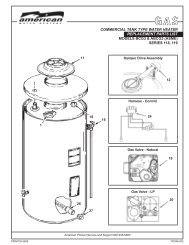
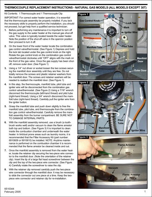
THERMOCOUPLE REPLACEMENT INSTRUCTIONS - NATURAL GAS MODELS (ALL MODELS EXCEPT 30T)Kit Contents: 1 <strong>Thermocouple</strong> and 1 <strong>Thermocouple</strong> ClipIMPORTANT: For correct water heater operation, it is essentialthat the thermocouple assembly be properly installed. If you lackthe necessary skills to properly perform the installation, you shouldnot proceed, but get help from a qualified service technician.1. Before performing any maintenance it is important to turn offthe gas supply to the water heater at the manual gas shut-offvalve. This valve is typically located beside the water heater.Note the position of the shut-off valve in the open/on positionthen proceed to turn it off.2. On the lower front of the water heater locate the combinationgas control valve/thermostat. (See Figure 1) Depress and holdthe lock tab located under the gas control knob on the right.Rotate the gas control knob on the combination gas controlvalve/thermostat clockwise until “OFF” aligns with the mark onthe front of the gas valve. Once the gas supply has been shutoff,remove outer door. (See Figure 1)3. Using a 1/4” nut driver or socket loosen the two screws securingthe manifold door assembly until they are free. Do nottotally remove the screws and plastic retainer washers fromthe manifold door. The screws and retainer washers will beneeded to reattach the manifold door. (See Figure 1)4. In this step, the thermocouple, manifold tube, pilot tube andigniter wire will be disconnected from the combination gascontrol valve/thermostat. (See Figure 2) Using a 7/16” wrenchdisconnect the thermocouple (left-hand thread) and pilot tube(right-hand thread). Using a 3/4” wrench disconnect the manifoldtube (right-hand thread). Carefully pull the igniter wire fromthe igniter button.5. Grasp the manifold tube and push down slightly to free themanifold tube, pilot tube, and thermocouple from the combinationgas control valve/thermostat. Carefully remove the manifoldassembly from the burner compartment. BE SURE NOTTO DAMAGE INTERNAL PARTS.6. With the manifold assembly removed, use a brush (a toothbrushworks well) and/or vacuum to clean the flame arrestorboth top and bottom. (See Figure 3) It is important to cleaninside the combustion chamber and underneath the waterheater. In lint/dust prone areas such as laundry rooms, it isrecommended that the Filter Accessory Kit (part number:6910609 or 6910610) be installed. NOTE: Anytime maintenanceis performed on the combustion chamber it is recommendedthat the flame arrestor be cleaned inside and out.7. Once the manifold assembly is removed from the water heater,locate the retainer clip securing the two-piece wire connectorto the manifold door. (Note the orientation of the retainerclip). Insert the tip of a large flat head screwdriver between theclip and the top of the two-piece wire connector. (See Figure4) Carefully rotate the screwdriver to raise the clip.8. With the retainer clip removed carefully push the two-piecewire connector through the manifold door. It may be necessaryto slide the connector out one piece at a time. Keep the twopiecewire connector and retainer clip for re-installation.Figure 1Gas Control KnobFigure 2<strong>Thermocouple</strong>Figure 3<strong>Thermocouple</strong>Manifold TubeManifold DoorScrewsManifoldTubeVacuumPilotTubeLock TabMarkIgniter WirePilot TubeFlame ArrestorIgniter WireFlame ArrestorManifoldDoorOuter Door6510344February 20051
9. Locate the clip holding the thermocouple to the pilot tube. (Ifyour model does not have a clip, proceed to the next step.)Before unsnapping the thermocouple from the clip note theclips location on the larger diameter section of the thermocouple.(See Figure 5)10. Locate the thermocouple where it connects to the rear of thepilot assembly. Pull the thermocouple from the rear of the pilotassembly as shown in Figure 6. NOTE: For clarity the burneris not shown in the photo. Do not remove the burner. Once thethermocouple is disconnected from the pilot assembly, it maynow be removed from the manifold door assembly.11. If your new thermocouple is pre-bent to the shape on page 4then skip to step 12. If your new thermocouple is coiled thenuse the bending template on page 4 as a guide to carefullybend the new thermocouple supplied with the kit. When bending,do not kink or crease the thermocouple. It is essential forthe proper operation of the water heater that the thermocouplebe bent smoothly without kinks or creases.12. Insert the tip of the thermocouple through the hole in the frontof the manifold door and route it in the same configuration asthe old thermocouple. (See Figure 7) IMPORTANT: It is essentialfor the proper operation of the water heater that the thermocouplebe routed correctly. For clarity purposes the burneris not shown in the photo.13. Insert the thermocouple tip into the hole provided in the pilotassembly. Then push the thermocouple completely forwarduntil it is seated against the pilot assembly bracket. (SeeFigure 8) An audible click is typically heard when the thermocoupleis fully seated. IMPORTANT: The thermocouple mustbe fully seated. For clarity purposes the burner is not shown inthe photo.14. Snap the thermocouple back into the clip connecting it to thepilot tube. (See Figure 9) If your water heater does not have aclip, reference the table below to determine the correct clip touse. Slide the clip over the pilot tube first, then snap the thermocoupleinto the clip. Use the template on page 4 for thelocation of the clip.<strong>Thermocouple</strong> Clip Table:This clip fits the following models:30 gallon (Short)40 gallon (Short & Tall)50 gallon (Tall)Figure 4Figure 5Figure 6Figure 7Retainer ClipClipManifoldTubeTwo PieceWire Connector<strong>Thermocouple</strong>Pilot Tube<strong>Thermocouple</strong>Pilot Tube<strong>Thermocouple</strong>Pilot TubeNote: Reference the model numberon your data plate for a T or Sindicating a Tall or Short model.15. Reinstall the two-piece wire connector in the manifold door.The igniter wire must be seated above the thermocouple inthe two-piece wire connector. It may be necessary to insertthe connector one side at a time. Once both sides of thetwo-piece wire connector are in place, secure it with theretainer clip.2
16. Carefully insert the manifold assembly into the combustionchamber making sure that the tip of the manifold assemblyengages with the slot in the bracket inside the combustionchamber. (See Figure 10) Once seated make sure there isno fiberglass insulation between the gasket and the combustionchamber.17. Securely tighten the two screws that hold the manifolddoor assembly to the skirt.Figure 8<strong>Thermocouple</strong> Fully SeatedPilot Bracket18. In this step the thermocouple, manifold tube, pilot tube,and igniter wire must be reconnected to the combinationgas control valve/thermostat. (See Figure 11 ) Using a 3/4”wrench (right-hand thread) reconnect the manifold tube.Reconnect the thermocouple (left-hand thread) using a 7/16”wrench. NOTE: When connecting the thermocouple tightenby hand, then use a wrench to tighten one quarter turn only.Reconnect the pilot tube (right-hand thread) using a 7/16”wrench. NOTE: Do not cross thread or apply any threadsealant to the fittings. Reconnect the igniter wire to theigniter button.19. Turn the gas supply on at the manual gas shut-off valve, andrefer to the lighting instructions on the outside of the waterheater. Check for leaks using a chloride-free soap and watersolution (bubbles forming indicate a leak) or other approvedmethod. Do not use open flame. ALL LEAKS MUST BEFIXED IMMEDIATELY. Ensure proper operation of the waterheater and reattach outer door.<strong>Thermocouple</strong>Figure 9<strong>Thermocouple</strong>ClipPilot AssemblyBracket Shownfor Clarity<strong>Thermocouple</strong>Figure 10Pilot TubeManifold SlotManifold TipFigure 11PilotTubeManifold Tube<strong>Thermocouple</strong>Igniter Wire3
THERMOCOUPLE BENDING TEMPLATE\INSTRUCTIONS4