Download Installation Instructions - American Water Heaters
Download Installation Instructions - American Water Heaters
Download Installation Instructions - American Water Heaters

Create successful ePaper yourself
Turn your PDF publications into a flip-book with our unique Google optimized e-Paper software.
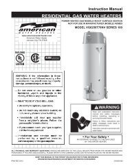
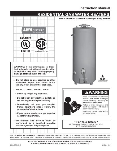
Instruction ManualRESIDENTIAL GAS WATER HEATERSNOT FOR USE IN MANUFACTURED (MOBILE) HOMESLow Lead Content• For Your Safety •AN ODORANT IS ADDED TO THE GAS USEDBY THIS WATER HEATER.ALL TECHNICAL AND WARRANTY QUESTIONS: SHOULD BE DIRECTED TO THE LOCAL DEALER FROM WHOM THE WATER HEATER WASPURCHASED. IF YOU ARE UNSUCCESSFUL, PLEASE WRITE TO THE COMPANY LISTED ON THE RATING PLATE ON THE WATER HEATER.Keep this manual in the pocket on heater for future referencewhenever maintenance adjustment or service is required.PRINTED 07121315628-001
SAFE INSTALLATION, USE AND SERVICEYour safety and the safety of others is extremely important in the installation, use and servicing of this water heater.Many safety-related messages and instructions have been provided in this manual and on your own water heater to warn you andothers of a potential injury hazard. Read and obey all safety messages and instructions throughout this manual. It is very importantthat the meaning of each safety message is understood by you and others who install, use or service this water heater.This is the safety alert symbol. It is used to alert you topotential personal injury hazards. Obey all safetymessages that follow this symbol to avoid possibleinjury or death.DANGERWARNINGCAUTIONCAUTIONDANGER indicates an imminentlyhazardous situation which, if not avoided,will result in injury or death.WARNING indicates a potentially hazardoussituation which, if not avoided, could resultin injury or death.CAUTION indicates a potentially hazardoussituation which, if not avoided, could result inminor or moderate injury.CAUTION used without the safety alertsymbol indicates a potentially hazardoussituation which, if not avoided, could result inproperty damage.All safety messages will generally tell you about the type of hazard, what can happen if you do not follow the safety message andhow to avoid the risk of injury.The California Safe Drinking <strong>Water</strong> and Toxic Enforcement Act requires the Governor of California to publish a list of substancesknown to the State of California to cause cancer, birth defects, or other reproductive harm, and requires businesses to warn ofpotential exposure to such substances.WARNING: This product contains a chemical known to the State of California to cause cancer, birth defects, or other reproductive harm.This water heater can cause low-level exposure to some of the substances included in the Act. This product is certified to complywith a maximum weighted average of 0.25% lead content as required in some areas.IMPORTANT DEFINITIONS• Qualified Installer: A qualified installer must have ability equivalent to a licensed tradesman in the fields of plumbing,air supply, venting and gas supply, including a thorough understanding of the requirements of the National Fuel GasCode as it relates to the installation of gas fired water heaters. The qualified installer must have a thoroughunderstanding of this instruction manual.• Service Agency: A service agency also must have ability equivalent to a licensed tradesman in the fields of plumbing,air supply, venting and gas supply, including a thorough understanding of the requirements of the National Fuel GasCode as it relates to the installation of gas fired water heaters. The service agency must also have a thoroughunderstanding of this instruction manual, and be able to perform repairs strictly in accordance with the service guidelinesprovided by the manufacturer.• Gas Supplier: The Natural Gas or Propane Utility or service which supplies gas for utilization by the gas burningappliances within this application. The gas supplier typically has responsibility for the inspection and code approval ofgas piping up to and including the Natural Gas meter or Propane storage tank of a building. Many gas suppliers alsooffer service and inspection of appliances within the building.2
GENERAL SAFETY3
TABLE OF CONTENTSSAFE INSTALLATION, USE AND SERVICE............................2GENERAL SAFETY..................................................................3TABLE OF CONTENTS.............................................................4INTRODUCTION.......................................................................4Preparing for the New <strong>Installation</strong>......................................4TYPICAL INSTALLATION.......................................................5,6LOCATING THE NEW WATER HEATER.............................. 7-9Facts to Consider About Location...................................7,8Insulation Blankets.............................................................8Combustion Air and Ventilation for AppliancesLocated in Unconfined Spaces..........................................8Combustion Air and Ventilation for AppliancesLocated in Confined Spaces...........................................8,9INSTALLING THE NEW WATER HEATER....................... 10-14<strong>Water</strong> Piping...............................................................10,11Closed <strong>Water</strong> System......................................................10Thermal Expansion..........................................................10Temperature-Pressure Relief Valve.................................11Filling the <strong>Water</strong> Heater...................................................12Venting........................................................................12,13Gas Piping..................................................................13,14Sediment Traps................................................................14LIGHTING & OPERATING INSTRUCTIONS.....................15,16TEMPERATURE REGULATION.............................................17FOR YOUR INFORMATION...............................................17,18Start Up Conditions.....................................................17,18Draft Hood Operation....................................................17Condensation...........................................................17,18Smoke/Odor..................................................................18Thermal Expansion.......................................................18Strange Sounds............................................................18Operational Conditions....................................................18Smelly <strong>Water</strong>.................................................................18“Air” in Hot <strong>Water</strong> Faucets............................................18High Temperature Shut Off System..............................18PERIODIC MAINTENANCE.............................................. 19-21Venting System Inspection..............................................19Burner Inspection.............................................................19Burner Cleaning...............................................................19Housekeeping.............................................................19,20Anode Rod Inspection.....................................................20Temperature-Pressure Relief Valve Operation................20Draining and Flushing......................................................20Drain Valve Washer Replacement...................................20Service.............................................................................21LEAKAGE CHECKPOINTS.....................................................21REPAIR PARTS.......................................................................22TROUBLESHOOTING GUIDELINES.....................................23WARRANTY.......................................................................InsertINTRODUCTIONThank You for purchasing this water heater. Properly installed andmaintained, it should give you years of trouble free service.Abbreviations Found In This Instruction Manual:• UL - Underwriters Laboratories Inc.• ANSI - <strong>American</strong> National Standards Institute• NFPA - National Fire Protection Association• ASME - <strong>American</strong> Society of Mechanical Engineers• AHRI - Air-Conditioning, Heating and Refrigeration Institute• CAN - Canada• EPACT - Energy Policy Act• CSA - Canadian Standards AssociationThis gas-fired water heater is design certified by UnderwritersLaboratories Inc. under <strong>American</strong> National Standard/CSA Standardfor Gas <strong>Water</strong> <strong>Heaters</strong> ANSI Z21.10.3 • CSA 4.3 (current edition).Preparing for the <strong>Installation</strong>1. Read the “General Safety” section, page 3 of this manualfirst and then the entire manual carefully. If you don’t followthe safety rules, the water heater will not operate properly. Itcould cause DEATH, SERIOUS BODILY INJURY AND/ORPROPERTY DAMAGE.This manual contains instructions for the installation, operation, andmaintenance of the gas-fired water heater. It also contains warningsthroughout the manual that you must read and be aware of. Allwarnings and all instructions are essential to the proper operation ofthe water heater and your safety. Since we cannot put everythingon the first few pages, READ THE ENTIRE MANUAL BEFOREATTEMPTING TO INSTALL OR OPERATE THE WATER HEATER.2. The installation must conform with these instructions and the localcode authority having jurisdiction. In the absence of local codes,installations shall comply with the National Fuel Gas Code ANSIZ223.1/NFPA 54 current addition. This publication is available fromthe CSA International, 8501 East Pleasant Valley Rd., ClevelandOhio 44131, or The National Fire Protection Association, 1Batterymarch Park, Quincy, MA 02269.3. If after reading this manual you have any questions or do notunderstand any portion of the instructions, call the local gas utilityor the manufacturer whose name appears on the rating plate.4. Carefully plan the place where you are going to put the waterheater. Correct combustion, vent action, and vent pipe installationare very important in preventing death from possible carbonmonoxide poisoning and fires. See Figures 3 and 8.Examine the location to ensure the water heater complies withthe “Locating the New <strong>Water</strong> Heater” section in this manual.5. For California installation this water heater must be braced,anchored, or strapped to avoid falling or moving during anearthquake. See instructions for correct installation procedures.<strong>Instructions</strong> may be obtained from California Office of the StateArchitect, 400 P Street, Sacramento, CA 95814.6. Massachusetts Code requires this water heater to be installed inaccordance with Massachusetts 248-CMR 2.00: State PlumbingCode and 248-CMR 5.00.4
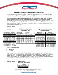
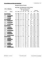
TYPICAL INSTALLATIONGET TO KNOW YOUR WATER HEATER - GAS MODELSABCDEFGHVent PipeDrafthoodAnodeHot <strong>Water</strong> OutletOutletInsulationGas SupplyManual Gas Shut-off ValveI Ground Joint UnionJ Sediment TrapK Inner DoorL Outer doorM UnionN Inlet <strong>Water</strong> Shut-off ValveO Cold <strong>Water</strong> InletP Inlet Dip TubeQRSTUVWXTemperature-Pressure Relief ValveRating PlateFlue Baffle(s)Gas Control Valve/ThermostatDrain ValvePilot and Main BurnerFlueMetal Drain Pan* INSTALL IN ACCORDANCE WITHLOCAL CODES.(T) GAS CONTROL VALVE/THERMOSTAT* SEDIMENT TRAP AS REQUIREDBY LOCAL CODES.* ALL PIPING MATERIALS TO BESUPPLIED BY CUSTOMERS.(V) PILOT & MAIN BURNER - NATURAL GAS(V) PILOT & MAIN BURNER - PROPANE GASTHERMOCOUPLEPILOTBURNERMAINBURNER**CLOSED WATER SYSTEMS ARE THOSEWITH BACK FLOW PREVENTION DEVICESINSTALLED IN THE WATER SERVICE LINE.FIGURE 1.5
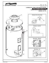
TYPICAL INSTALLATIONMIXING VALVE USAGEFIGURE 2.This water heater has been design certified as complying with ANSI Z21.10.3current edition for water heaters and is considered suitable for:<strong>Water</strong> (Potable) Heating and Space Heating: All models areconsidered suitable for water (potable) heating and space heating.6HOTTER WATER CAN SCALD:<strong>Water</strong> heaters are intended to produce hot water. <strong>Water</strong> heated toa temperature which will satisfy space heating, clothes washing,dish washing, and other sanitizing needs can scald and permanentlyinjure you upon contact. Some people are more likely to bepermanently injured by hot water than others. These include theelderly, children, the infirm, or physically/mentally handicapped. Ifanyone using hot water in your home fits into one of these groupsor if there is a local code requiring a certain temperature waterat the hot water tap, then you must take special precautions. Inaddition to using the lowest possible temperature setting thatsatisfies your hot water needs, a means such as a *Mixing Valveshould be used at the hot water taps used by these people or atthe water heater. Mixing valves are available at plumbing supplyor hardware stores. Consult a qualified installer or service agency.Follow mixing valve manufacturer’s instructions for installation ofthe valves. Before changing the factory setting on the thermostat,read the “Temperature Regulation” section in this manual, seeFigures 15 and 16.
LOCATING THE NEW WATER HEATERFacts to Consider About the LocationCarefully choose an indoor location for the new water heater,because the placement is a very important consideration for thesafety of the occupants in the building and for the most economicaluse of the water heater. This water heater is not for use inmanufactured (mobile) homes or outdoor installation.Whether replacing an old water heater or putting the water heaterin a new location, the following critical points must be observed:1. Select a location indoors as close as practical to the gas vent orchimney to which the water heater vent is going to be connected,and as centralized with the water piping system as possible.2. Selected location must provide adequate clearances forservicing and proper operation of the water heater.Keep combustibles such as boxes, magazines, clothes, etc., awayfrom the water heater area.<strong>Installation</strong> of the water heater must be accomplished in such a mannerthat if tank or any connections should leak, the flow will not causedamage to the structure. For this reason, it is not advisable to installwater heater in an attic or upper floor. When such locations cannot beavoided, a suitable metal drain pan should be installed under the waterheater. Metal drain pans are available at your local hardware store. Sucha metal drain pan must have a minimum length and width of at least 2”(51 mm) greater than the water heater dimensions and must be pipedto an adequate drain. The pan must not restrict combustion air flow.<strong>Water</strong> heater life depends upon water quality, water pressure and theenvironment in which the water heater is installed. <strong>Water</strong> heaters aresometimes installed in locations where leakage may result in propertydamage, even with the use of a drain pan piped to a drain. However,unanticipated damage can be reduced or prevented by a leak detectoror water shut-off device used in conjunction with a piped drain pan.These devices are available from some plumbing supply wholesalersand retailers, and detect and react to leakage in various ways:• Sensors mounted in the drain pan that trigger an alarm or turn offthe incoming water to the water heater when leakage is detected.• Sensors mounted in the drain pan that turn off the water supplyto the entire home when water is detected in the drain pan.• <strong>Water</strong> supply shut-off devices that activate based on the waterpressure differential between the cold water and hot water pipesconnected to the water heater.• Devices that will turn off the gas supply to a gas water heaterwhile at the same time shutting off its water supply.INSTALLATIONS IN AREAS WHERE FLAMMABLE LIQUIDS(VAPORS) ARE LIKELY TO BE PRESENT OR STORED (GARAGES,STORAGE AND UTILITY AREAS, ETC.): Flammable liquids (such asgasoline, solvents, propane [LP or butane, etc.] and other substancessuch as adhesives, etc.) emit flammable vapors which can be ignited bya gas water heater’s pilot light or main burner. The resulting flashbackand fire can cause death or serious burns to anyone in the area, as wellas property damage. If installation in such areas is your only option,then the installation must be accomplished in a way that the pilot flameand main burner flame are elevated from the floor at least 18 inches.While this may reduce the chances of flammable vapors, from a floorspill being ignited, gasoline and other flammable substances shouldnever be stored or used in the same room or area containing a gaswater heater or other open flame or spark producing appliance. NOTE:Flammable vapors may be drawn by air currents from other areas ofthe structure to the appliance.Also, the water heater must be located and/or protected so it is notsubject to physical damage by a moving vehicle.This water heater must not be installed directly on carpeting.Carpeting must be protected by metal or wood panel beneath thewater heater extending beyond the full width and depth of waterheater by at least 3” (76.2 mm) in any direction, or if the water heateris installed in an alcove or closet, the entire floor must be covered bythe panel. Failure to heed this warning may result in a fire hazard.7
Minimum clearances between the water heater and combustiblematerials are 0 inch at the sides and rear, 4” (102 mm) at the front,and 6” (153 mm) from the vent pipe. Clearance from the top of thejacket is 12” (305 mm) on most models. Note that a lesser dimensionmay be allowed on some models, refer to the label attached adjacentto the gas control valve on the water heater, see Figure 3.INSULATION BLANKETSFIGURE 3.Insulation blankets are available to the general public for external useon gas water heaters but are not necessary with these products. Thepurpose of an insulation blanket is to reduce the standby heat lossencountered with storage tank heaters. Your water heater meets orexceeds the EPACT standards with respect to insulation and standbyloss requirements, making an insulation blanket unnecessary.Should you choose to apply an insulation blanket to this heater, youshould follow these instructions (For identification of componentsmentioned below, see Figure 1). Failure to follow these instructionscan restrict the air flow required for proper combustion, potentiallyresulting in fire, asphyxiation, serious personal injury or death.• Do not apply insulation to the top of the water heater, as this willinterfere with safe operation of the draft hood.• Do not cover the outer door, gas control valve/thermostat ortemperature & pressure relief valve.A gas water heater cannot operate properly without the correct amountof air for combustion. Do not install in a confined area such as a closet,unless you provide air as shown in the “Locating The New <strong>Water</strong> Heater”section. Never obstruct the flow of ventilation air. If you have any doubtsor questions at all, call your gas supplier. Failure to provide the properamount of combustion air can result in a fire or explosion and causedeath, serious bodily injury, or property damage.• Do not allow insulation to come within 2” (50.8 mm) of the floor toprevent blockage of combustion air flow to the burner.• Do not cover the instruction manual. Keep it on the side of thewater heater or nearby for future reference.• Do obtain new warning and instruction labels from the manufacturerfor placement on the blanket directly over the existing labels.• Do inspect the insulation blanket frequently to make certain itdoes not sag, thereby obstructing combustion air flow.FIGURE 4.If this water heater will be used in beauty shops, barber shops, cleaningestablishments, or self-service laundries with dry cleaning equipment,it is imperative that the water heater or water heaters be installed sothat combustion and ventilation air be taken from outside these areas.Propellants of aerosol sprays and volatile compounds, (cleaners,chlorine based chemicals, refrigerants, etc.) in addition to being highlyflammable in many cases, will also change to corrosive hydrochloricacid when exposed to the combustion products of the water heater.The results can be hazardous, and also cause product failure.8Combustion Air and Ventilation forAppliances Located in Unconfined SpacesUnconfined Space is space whose volume is not less than50 cubic feet per 1,000 Btu per hour (4.8 m 3 per kW) of the aggregateinput rating of all appliances installed in that space. Roomscommunicating directly with the space in which the appliances areinstalled, through openings not furnished with doors, are considereda part of the unconfined space.In unconfined spaces in buildings, infiltration may be adequate to provideair for combustion, ventilation and dilution of flue gases. However, inbuildings of tight construction (for example, weather stripping, heavilyinsulated, caulked, vapor barrier, etc.), additional air may need tobe provided using the methods described in “Combustion Air andVentilation for Appliances Located in Confined Spaces.”Combustion Air and Ventilation forAppliances Located in Confined SpacesConfined Space is a space whose volume is less than 50 cubicfeet per 1,000 Btu per hour (4.8 m 3 per kW) of the aggregate inputrating of all appliances installed in that space.
The valve must be marked with a maximum set pressure not toexceed the marked maximum working pressure of the water heater(150 psi = 1,035 kPa) and a discharge capacity not less than the waterheater input rate as shown on the model rating plate.For safe operation of the water heater, the relief valve must not beremoved from its designated opening nor plugged.The temperature-pressure relief valve must be installed directly intothe fitting of the water heater designed for the relief valve. Positionthe valve downward and provide tubing so that any discharge will exitonly within 6” (153 mm) above, or at any distance below the structuralfloor. Be certain that no contact is made with any live electrical part.The discharge opening must not be blocked or reduced in size underany circumstances. Excessive length, over 30’ (9.14 m), or use ofmore than four elbows can cause restriction and reduce the dischargecapacity of the valve, see Figure 10.No valve or other obstruction is to be placed between the relief valveand the tank. Do not connect tubing directly to discharge drain unlessa 6 inch air gap is provided. To prevent bodily injury, hazard to life, orproperty damage, the relief valve must be allowed to discharge waterin quantities should circumstances demand. If the discharge pipe isnot connected to a drain or other suitable means, the water flow maycause property damage.FIGURE 9.Figure 9 shows the typical attachment of the water piping to the waterheater. The water heater is equipped with 1” NPT threaded nipple(75 gallon models) or 1.25” NPT threaded nipple (100 gallon models)water connections.NOTE: If using copper tubing, solder tubing to an adapter beforeattaching the adapter to the cold water inlet connection. Do notsolder the cold water supply line directly to the cold water inlet.It will harm the dip tube and damage the tank.Temperature-Pressure Relief ValveThe Discharge Pipe:• Should not be smaller in size than the outlet pipe size of the valve, orhave any reducing couplings or other restrictions.• Should not be plugged or blocked.• Should be of material listed for hot water distribution.• Should be installed so as to allow complete drainage of both thetemperature-pressure relief valve, and the discharge pipe.• Must terminate a maximum of six inches above a floor drain or externalto the building. In cold climates, it is recommended that the dischargepipe be terminated at an adequate drain inside the building.• Should not have any valve between the relief valve and tank.This heater is provided with a properly certified combinationtemperature - pressure relief valve by the manufacturer.The valve is certified by a nationally recognized testing laboratorythat maintains periodic inspection of production of listed equipment ofmaterials as meeting the requirements for Relief Valves for Hot <strong>Water</strong>Supply Systems, ANSI Z21.22 • CSA 4.4, and the code requirementsof ASME.If replaced, the valve must meet the requirements of local codes, butnot less than a combination temperature and pressure relief valvecertified as indicated in the above paragraph.11The temperature-pressure relief valve must be manually operated atleast once a year. Caution should be taken to ensure that (1) no oneis in front of or around the outlet of the temperature-pressure reliefvalve discharge line, and (2) the water manually discharged will notcause any bodily injury or property damage because the water maybe extremely hot.If after manually operating the valve, it fails to completely reset andcontinues to release water, immediately close the cold water inletto the water heater, follow the draining instructions, and replace thetemperature-pressure relief valve with a new one.
FIGURE 10.Filling the <strong>Water</strong> HeaterNever use this water heater unless it is completely full of water.To prevent damage to the tank, the tank must be filled with water.<strong>Water</strong> must flow from the hot water faucet before turning “ON” gasto the water heater.To fill the water heater with water:1. Close water heater drain valve by turning handle to the right(clockwise). The drain valve is on the lower front of water heater.2. Open the cold water supply valve to the water heater.NOTE: The cold water supply valve must be left open whenthe water heater is in use.3. To insure complete filling of the tank, allow air to exit by openingthe nearest hot water faucet. Allow water to run until a constantflow is obtained. This will let air out of the water heater and piping.4. Check all water piping and connections for leaks. Repair as needed.VENT DAMPERS - Any vent damper, whether it is operated thermallyor otherwise must be removed if its use inhibits proper drafting ofthe water heater.Thermally Operated Vent Dampers: this gas-fired water heater has athermal efficiency at or above 80% which may produce a relatively lowflue gas temperature. Such temperatures may not be high enough toproperly open thermally operated vent dampers. This would causespillage of the flue gases and may cause carbon monoxide poisoning.Vent dampers must bear evidence of certification as complying withthe current edition of the <strong>American</strong> National Standard ANSI Z21.66CGA 6.14 (covering electrically and mechanically actuated ventdampers). Before installation of any vent damper, consult the localgas utility for further information.To insure proper venting of this gas-fired water heater, the correctvent pipe diameter must be utilized. Any additions or deletions ofother gas appliances on a common vent with this water heater mayadversely affect the operation of the water heater. Consult your gassupplier if any such changes are planned.For proper venting in certain installations, a larger diameter vent pipemay be necessary. Consult your gas supplier to aid you in determiningthe proper venting for your water heater from the vent tables in thecurrent edition of the National Fuel Gas Code ANSI Z223.1/NFPA 54.Periodically check the venting system for signs of obstruction ordeterioration and replace if needed.The combustion and ventilation air flow must not be obstructed.The water heater with draft hood installed must be connected to achimney or listed vent pipe system, which terminates to the outdoors.Never operate the water heater unless it is vented to the outdoorsand has adequate air supply to avoid risks of improper operation,explosion or asphyxiation.• For proper draft hood attachment, the draft hood legs may beangled slightly inward.• Place the draft hood legs in the receiving holes on the top of thewater heater. The legs will snap in the holes to give a tight fit.Secure draft hood with the supplied brackets.• Place the vent pipe over the draft hood. With the vent pipe in position,drill a small hole through both the vent pipe and draft hood. Securethem together with a sheet metal screw, see Figure 11.Obstructed or deteriorated vent systems may present serious healthrisk or asphyxiation.Venting12FIGURE 11.The vent pipe from the water heater must be no less than the diameterof the draft hood outlet on the water heater and must slope upwardat least 1/4 inch per linear foot (21 mm per meter), see Figure 12.All vent gases must be completely vented to the outdoors of thestructure (dwelling). Install only the draft hood provided with thenew water heater and no other draft hood.Vent pipes must be secured at each joint with sheet metalscrews.
Make sure the gas supplied is the same type listed on the modelrating plate. The inlet gas pressure must not exceed 14 inchwater column (2.6 kPa) for natural and propane (L.P.) gas. Theminimum inlet gas pressure shown on the rating plate is thatwhich will permit firing at rated input.If the gas control valve is subjected to pressures exceeding1/2 pound per square inch (3.5 kPa), the damage to the gascontrol valve could result in a fire or explosion from leaking gas.FIGURE 12.There must be a minimum of 6” (153 mm) clearance between singlewall vent pipe and any combustible material. Fill and seal anyclearance between single wall vent pipe and combustible surfaceswith mortar mix, cement, or other noncombustible substance. Forother than single wall, follow vent pipe manufacturer’s clearancespecifications. To insure a tight fit of the vent pipe in a brick chimney,seal around the vent pipe with mortar mix cement.Failure to have required clearances between vent piping andcombustible material will result in a fire hazard.Be sure vent pipe is properly connected to prevent escape ofdangerous flue gases which could cause deadly asphyxiation.If the main gas line shut-off serving all gas appliances isused, also turn “off” the gas at each appliance. Leave allgas appliances shut “off” until the water heater installation iscomplete.A gas line of sufficient size must be run to the water heater.Consult the current edition of National Fuel Gas Code ANSIZ223.1/NFPA 54 and your gas supplier concerning pipe size.There must be:• A readily accessible manual shut off valve in the gas supplyline serving the water heater, and• A sediment trap ahead of the gas control valve to helpprevent dirt and foreign materials from entering the gascontrol valve.• A flexible gas connector or a ground joint union betweenthe shut off valve and control valve to permit servicing ofthe unit.Be sure to check all the gas piping for leaks before lighting thewater heater. Use a soapy water solution, not a match or openflame. Rinse off soapy solution and wipe dry.The minimum inlet gas pressure shown on the rating plate isthat which will permit firing at the rated input.Chemical vapor corrosion of the flue and vent system may occurif air for combustion contains certain chemical vapors. Spray canpropellants, cleaning solvents, refrigerator and air conditionerrefrigerants, swimming pool chemicals, calcium and sodium chloride,waxes, bleach and process chemicals are typical compounds whichare potentially corrosive.Gas Piping13<strong>Water</strong> heaters covered in this manual have been tested andapproved for installation at elevations up to 7,700 feet (2,347m) above sea level. For installation above 7,700 feet (2,347 m),the water heater’s Btu input should be reduced at the rate of4 percent for each 1,000 feet (305 m) above sea level whichrequires replacement of the burner orifice in accordance withthe National Fuel Gas Code ANSI Z223.1/NFPA 54. Contactyour local gas supplier for further information.Failure to replace the standard orifice with the proper highaltitude orifice when installed at elevations above 7,700 feet(2,347 m) could result in improper and inefficient operation ofthe water heater producing carbon monoxide gas in excessof the safe limits. This could result in serious injury or death.Contact your local gas supplier for any specific changes thatmay be required in your area.
FIGURE 14. GAS PIPING WITH ALLBLACK IRON PIPE TO GAS CONTROL.Use pipe joint compound or teflon tape marked as being resistantto the action of petroleum [Propane (L.P.)] gases.The water heater and its gas connection must be leak tested beforeplacing the water heater in operation.The water heater and its individual shut-off valve shall bedisconnected from the gas supply piping system during any pressuretesting of that system at test pressures in excess of 1/2 pound persquare inch (3.5 kPa). It shall be isolated from the gas supply pipingsystem by closing its individual manual shut-off valve during anypressure testing of the gas supply piping system at test pressuresequal to or less than 1/2 pound per square inch (3.5 kPa).SEDIMENT TRAPSA sediment trap shall be installed as close to the inlet of the waterheater as practical at the time of water heater installation. Thesediment trap shall be either a tee fitting with a capped nipple in thebottom outlet or other device recognized as an effective sedimenttrap. If a tee fitting is used, it shall be installed in conformance withone of the methods of installation shown in Figures 13 and 14.Connecting the gas piping to the gas control valve of the waterheater can be accomplished by either of the two methods shown inFigures 13 and 14.FIGURE 13. GAS PIPING WITH FLEXIBLE CONNECTOR.Contaminants in the gas lines may cause improper operation ofthe gas control valve that may result in fire or explosion. Beforeattaching the gas line be sure that all gas pipe is clean on theinside. To trap any dirt or foreign material in the gas supply line,a sediment trap must be incorporated in the piping. The sedimenttrap must be readily accessible. Install in accordance with the“Gas Piping” section. Refer to the current edition of the NationalFuel Gas Code, ANSI Z223.1/NFPA 54.14
FOR YOUR SAFETY READ BEFORE LIGHTINGWARNING: If you do not follow these instructions exactly, a fire orexplosion may result causing property damage, personal injury or loss of life.BEFORE LIGHTING: ENTIRE SYSTEM MUST BE FILLED WITH WATER AND AIR PURGED AT FAUCETS.A. This appliance has a pilot which must be lighted by hand.When lighting the pilot, follow these instructions exactly.B. BEFORE LIGHTING: smell all around the appliancearea for gas. Be sure to smell next to the floor becausesome gas is heavier than air and will settle on the floor.WHAT TO DO IF YOU SMELL GAS• Do not try to light any appliance.• Do not touch any electric switch; do not useany phone in your building.• Immediately call your gas supplier from aneighbor’s phone. Follow the gas supplier’sinstructions.• If you cannot reach your gas supplier, call thefire department.C. Use only your hand to push down or turn the gas controlknob. Never use tools. If the knob will not push down orturn by hand, don’t try to repair it, call a qualified servicetechnician. Force or attempted repair may result in a fireor explosion.D. Do not use this appliance if any part has been underwater. Immediately contact a qualified installer or serviceagency to replace a flooded water heater. Do not attemptto repair the unit! It must be replaced!LIGHTING INSTRUCTIONSGAS CONTROLTOP VIEWFIGURE “D”1. STOP! Read the safety information above onthis label.2. Set the thermostat to the lowest setting by turningthermostat dial fully clockwise until it stops.3. Push the gas control knob down slightly and turn clockwiseto “OFF” (Figure A).NOTE: Gas control knob CANNOT be turned from “PILOT”to “OFF” unless it is pushed down slightly. Do not force.4. Remove the inner and outer doors located below andbehind the gas control unit.5. Wait five (5) minutes to clear out any gas. If you thensmell gas STOP! Follow “B” in the safety informationabove on this label. If you do not smell gas, go to thenext step.6. Find Pilot. Follow metal tube from the bottom , right of thegas control to the pilot burner. (Figure D).7. Turn gas control knob counterclockwise to “PILOT”(Figure B).8. Push gas control knob down all the way and hold it down.Immediately light the pilot with a match. Continue to holdthe gas control knob down for about one (1) minuteafter the pilot is lit. Release the gas control knob and itwill pop back up. Pilot should remain lit. If it goes out,repeat Steps 3 through 8. It may take several minutes forair to clear the lines, before the pilot will light.• If knob does not pop up when released, stop andimmediately call your service technician or gassupplier.• If the pilot will not stay lit after several tries, turn thegas control knob to “OFF” (Figure A) and call yourservice technician or gas supplier.9. Replace inner and outer burner doors.10. At arm’s length away, turn the gas control knobcounterclockwise to “ON” (Figure C).11. Set thermostat to desired setting (See Figure).CAUTION: Hotter water increases the risk ofscald injury. Consult the instruction manualbefore changing temperature.TO TURN OFF GAS TO APPLIANCE1. Set the thermostat to lowest setting. 2. Push gas control knob down slightly and turn clockwiseto “OFF”. Do not force, see Figure A.16
TEMPERATURE REGULATIONShort repeated heating cycles caused by small hot water uses cancause temperatures at the point of use to exceed the thermostat settingby up to 30°F (16.7°C). If you experience this type of use you shouldconsider using lower temperature settings to reduce scald hazards.Any water heater’s intended purpose is to heat water. Hot water isneeded for cleansing, cleaning, and sanitizing (bodies, dishes, clothing).Untempered hot water can present a scald hazard. Depending on thetime element, and the people involved (adults, children, elderly, infirm,etc.) scalding may occur at different temperatures.Never allow small children to use a hot water tap, or to draw their ownbath water. Never leave a child or handicapped person unattendedin a bathtub or shower.NOTE: A water temperature range of 120°F-140°F (49°C-60°C) isrecommended by most dishwasher manufacturers.The thermostat of this water heater has been factory set at its lowestposition (pilot lighting). It is adjustable and must be reset tothe desired temperature setting to reduce the risk of scald injury.The mark ( ) indicative of approximately 120°F (49°C) is preferredstarting point. Some States have a requirement for a lower setting.Turn the water temperature dial clockwise ( ) to decrease thetemperature, or counterclockwise ( ) to increase the temperature.Should overheating occur or the gas supply fail to shut off, turn offthe manual gas control valve to the water heater.HOTTER WATER CAN SCALD: <strong>Water</strong> heaters are intended toproduce hot water. <strong>Water</strong> heated to a temperature which will satisfyspace heating, clothes washing, dish washing, and other sanitizingneeds can scald and permanently injure you upon contact. Somepeople are more likely to be permanently injured by hot water thanothers. These include the elderly, children, the infirm, or physically/mentally handicapped. If anyone using hot water in your homefits into one of these groups or if there is a local code or state lawrequiring a certain temperature water at the hot water tap, then youmust take special precautions. In addition to using the lowest possibletemperature setting that satisfies your hot water needs, a means suchas a mixing valve should be used at the hot water taps used by thesepeople or at the water heater. Mixing valves are available at plumbingsupply or hardware stores, see Figure 2. Follow manufacturer’sinstructions for installation of the valves. Before changing the factorysetting on the thermostat, read the “Temperature Regulation” sectionin this manual, see Figures 15 and 16.<strong>Water</strong>Temperature°F (°C)FIGURE 15.Time for 1st Degree Burn(Less Severe Burns)Time for Permanent Burns2nd & 3rd Degree(Most Severe Burns)110 (43) (normal shower temp.)116 (47) (pain threshold)116 (47) 35 minutes 45 minutes122 (50) 1 minute 5 minutes131 (55) 5 seconds 25 seconds140 (60) 2 seconds 5 seconds149 (65) 1 second 2 seconds154 (68) instantaneous 1 second(U.S. Government Memorandum, C.P.S.C., Peter L. Armstrong, Sept. 15, 1978)FIGURE 16.START UP CONDITIONSDRAFT HOOD OPERATIONCheck draft hood operation by performing a worst casedepressurization of the building. With all doors and windows closed,and with all air handling equipment and exhaust fans operating suchas furnaces, clothes dryers, range hoods and bathroom fans, amatch flame should still be drawn into the draft hood of the waterheater with its burner firing. If the flame is not drawn toward thedraft hood, shut off water heater and make necessary air supplychanges to correct.CONDENSATIONWhenever the water heater is filled with cold water, somecondensate will form while the burner is on. A water heater mayTempératureFOR YOUR INFORMATIONde I'eau17Délai pour des brûlures Délai pour des brûluresau 1er degré permanentes au 2e et 3e degrés°C (°F) (brûlures moins graves) (brûlures les plus graves)43 (110) (temp. normale d’une douche)appear to be leaking when in fact the water is condensation. This47 (116) (seuil de douleur)usually happens when:47 (116) 35 minutes 45 minutesa. 50 A new (122) water heater 1 is minute filled with cold water for 5 minutes the first time.b. 55 Burning (131) gas produces 5 secondes water vapor in water 25 heaters, secondes particularly60 high (140) efficiency models 2 secondes where flue temperatures 5 secondes are lower.c. Large amounts of hot water are used in a short time and the refill65 (149) 1 seconde 2 secondeswater in the tank is very cold.68 (154) instantaneous 1 secondeMoisture (U.S. Government from the Memorandum, products of C.P.S.C., combustion Peter L. condense Armstrong, Sept. on the 15, 1978) coolertank surfaces and form drops of water which may fall onto the burneror other hot surfaces to produce a “sizzling” or “frying” noise.Excessive condensation can cause pilot outage due to water runningdown the flue tube onto the main burner and putting out the pilot.
Because of the suddenness and amount of water, condensationwater may be diagnosed as a “tank leak”. After the water in thetank warms up (about 1-2 hours), the condition should disappear.Do not assume the water heater is leaking until there has beenenough time for the water in the tank to warm up.An undersized water heater will cause more condensation. The waterheater must be sized properly to meet the family’s demands for hotwater including dishwashers, washing machines and shower heads.Excessive condensation may be noticed during the winter and earlyspring months when incoming water temperatures are at their lowest.Good venting is essential for a gas fired water heater to operate properlyas well as to carry away products of combustion and water vapor.SMOKE/ODORIt is not uncommon to experience a small amount of smoke and odorduring the initial start-up. This is due to burning off of oil from metalparts, and will disappear in a short while.THERMAL EXPANSIONconditions will cause a reaction between this rod and the water.The most common complaint associated with the anode rod is oneof a “rotten egg smell” in the hot water. This odor is derived fromhydrogen sulfide gas dissolved in the water. The smell is the resultof four factors which must all be present for the odor to develop:a. A concentration of sulfate in the supply water.b. Little or no dissolved oxygen in the water.c. A sulfate reducing bacteria which has accumulated within thewater heater (this harmless bacteria is nontoxic to humans).d. An excess of active hydrogen in the tank. This is caused by thecorrosion protective action of the anode.Smelly water may be eliminated or reduced in some water heatermodels by replacing the anode(s) with one of less active material, andthen chlorinating the water heater tank and all hot water lines. Contactthe local water heater supplier or service agency for further informationconcerning an Anode Replacement Kit and this chlorination treatment.If the smelly water persists after the anode replacement and chlorinationtreatment, we can only suggest that chlorination or aeration of thewater supply be considered to eliminate the water problem.Do not remove the anode leaving the tank unprotected. By doingso, all warranty on the water heater tank is voided.“AIR” IN HOT WATER FAUCETSAs water is heated, it expands (thermal expansion). In a closedsystem the volume of water will grow when it is heated. As thevolume of water grows there will be a corresponding increase inwater pressure due to thermal expansion. Thermal expansion cancause premature tank failure (leakage). This type of failure is notcovered under the limited warranty. Thermal expansion can alsocause intermittent Temperature-Pressure Relief Valve operation:water discharged from the valve due to excessive pressure buildup. This condition is not covered under the limited warranty. TheTemperature-Pressure Relief Valve is not intended for the constantrelief of thermal expansion.A properly sized thermal expansion tank must be installed on allclosed systems to control the harmful effects of thermal expansion.Contact a local plumbing service agency to have a thermal expansiontank installed.STRANGE SOUNDSPossible noises due to expansion and contraction of some metalparts during periods of heat-up and cool-down do not necessarilyrepresent harmful or dangerous conditions.Condensation causes sizzling and popping within the burner areaduring heating and cooling periods and should be considered normal.See “Condensation” in this section.Operational ConditionsSmelly <strong>Water</strong>In each water heater there is installed at least one anode rod (seeparts section) for corrosion protection of the tank. Certain waterHYDROGEN GAS: Hydrogen gas can be produced in a hot watersystem that has not been used for a long period of time (generallytwo weeks or more). Hydrogen gas is extremely flammable andexplosive. To prevent the possibility of injury under these conditions,we recommend the hot water faucet, located farthest away, beopened for several minutes before any electrical appliances which areconnected to the hot water system are used (such as a dishwasheror washing machine). If hydrogen gas is present, there will probablybe an unusual sound similar to air escaping through the pipe as thehot water faucet is opened. There must be no smoking or open flamenear the faucet at the time it is open.HIGH WATER TEMPERATURE SHUT OFF SYSTEMThis water heater is equipped with an automatic gas Shut-off system.This system works when high water temperatures are present. Thehigh temperature Shut-off is built into the gas control valve. It isnon-resettable. If the high temperature Shut-off activates, the gascontrol valve must be replaced. Contact your gas supplier or serviceagency. Turn “OFF” the entire gas supply to the water heater.18
PERIODIC MAINTENANCEVenting System InspectionYou should check for sooting. Soot is not normal and will impairproper combustion.Soot build-up indicates a problem that requires correction beforefurther use. Turn “OFF” gas to water heater and leave off until repairsare made, because failure to correct the cause of the sooting canresult in a fire causing death, serious injury, or property damage.NATURALPROPANEAt least once a year a visual inspection should be made of the ventingsystem. You should look for:1. Obstructions which could cause improper venting. Thecombustion and ventilation air flow must not be obstructed.2. Damage or deterioration which could cause improper venting orleakage of combustion products.3. Rusted flakes around top of water heater.Be sure the vent piping is properly connected to prevent escape ofdangerous flue gases which could cause deadly asphyxiation.Obstructions and deteriorated vent systems may present serioushealth risk or asphyxiation.Chemical vapor corrosion of the flue and vent system may occurif air for combustion contains certain chemical vapors. Spray canpropellants, cleaning solvents, refrigerator and air conditionerrefrigerants, swimming pool chemicals, calcium and sodium chloride,waxes, bleach and process chemicals are typical compounds whichare potentially corrosive.Burner CleaningFIGURE 17.If inspection of the burner shows that cleaning is required, turn the gascontrol knob clockwise ( ) to the “OFF” position, depressing slightly.NOTE: The knob cannot be turned from “PILOT” to “OFF” unlessknob is depressed slightly. DO NOT FORCE.Loose deposits on or around the burner can be removed by carefullyusing the hose of a vacuum cleaner inserted through the access doorof the water heater. If the burner needs to be removed for additionalcleaning, call a service agency to remove and clean the burner andcorrect the problem that required the burner to be cleaned.HousekeepingIf after inspection of the vent system you found sooting ordeterioration, something is wrong. Call the local gas utility tocorrect the problem and clean or replace the flue and venting beforeresuming operation of the water heater.Burner InspectionFlood damage to a water heater may not be readily visible orimmediately detectable. However, over a period of time a floodedwater heater will create dangerous conditions which can causeDEATH, SERIOUS BODILY INJURY, OR PROPERTY DAMAGE.Contact a qualified installer or service agency to replace a floodedwater heater. Do not attempt to repair the unit! It must be replaced!At least once a year a visual inspection should be made of the mainburner and pilot burner, see Figure 17.19Vacuum around base of water heater for dust, dirt, and lint on aregular basis.
INSTALLED IN SUITABLE AREA: To insure sufficient ventilationand combustion air supply, proper clearances from the water heatermust be maintained. See “Locating the New <strong>Water</strong> Heater” section.Combustible materials such as clothing, cleaning materials, orflammable liquids, etc. must not be placed against or adjacent tothe water heater which can cause a fire.ANODE ROD INSPECTIONIn replacing the anode:1. Turn off gas supply to the water heater.2. Shut off the water supply and open a nearby hot water faucetto depressurize the water tank.3. Drain approximately 5 gallons of water from tank. (Referto “Draining and Flushing” for proper procedures). Closedrain valve.4. Remove old anode rod.5. Use Tefl on® tape or approved pipe sealant on threads andinstall new anode rod.6. Turn on water supply and open a nearby hot water faucetto purge air from water system. Check for any leaks andimmediately correct any if found.Each water heater contains at least one anode rod, which willslowly deplete (due to electrolysis) prolonging the life of thewater heater by protecting the glass-lined tank from corrosion.Adverse water quality, hotter water temperatures, high hot waterusage, and water softening methods can increase the rate ofanode rod depletion. Once the anode rod is depleted, the tankwill start to corrode, eventually developing a leak.Certain water conditions will cause a reaction between the anoderod and the water. The most common complaint associated withthe anode rod is a “rotten egg smell” produced from the presenceof hydrogen sulfi de gas dissolved in the water. IMPORTANT: Donot remove this rod permanently as it will void any warranties. Aspecial anode rod may be available if water odor or discolorationoccurs. NOTE: This rod may reduce but not eliminate water odorproblems. The water supply system may require special fi ltrationequipment from a water conditioning company to successfullyeliminate all water odor problems.Artifi cially softened water is exceedingly corrosive because theprocess substitutes sodium ions for magnesium and calciumions. The use of a water softener may decrease the life of thewater heater tank.The anode rod should be inspected after a maximum of threeyears and annually thereafter until the condition of the anoderod dictates its replacement. NOTE: Artifi cially softened waterrequires the anode rod to be inspected annually.7. Restart the water heater as directed in this manual. See theRepair Parts Illustration for anode rod location.Temperature-PressureRelief Valve OperationThe temperature-pressure relief valve must be manually operatedat least once a year.When checking the temperature-pressure relief valve operation,make sure that (1) no one is in front of or around the outlet of thetemperature-pressure relief valve discharge line, and (2) that thewater discharge will not cause any property damage, as the watermay be extremely hot, see Figure 18.The following are typical (but not all) signs of a depletedanode rod:• The majority of the rods diameter is less than 3/8”.• Significant sections of the support wire (approx. 1/3 or moreof the anode rod’s length) are visible.FIGURE 18.If the anode rod show signs of either or both it should be replaced.NOTE: Whether re-installing or replacing the anode rod, check forany leaks and immediately correct if found.20FIGURE 19.If after manually operating the valve, it fails to completely reset andcontinues to release water, immediately close the cold water inletto the water heater, follow the draining instructions, and replacethe temperature-pressure relief valve with a new one.If the temperature-pressure relief valve on the water heater weepsor discharges periodically, this may be due to thermal expansion.You may have a check valve installed in the water line or a watermeter with a check valve. Consult your local water supplier orservice agency for further information. Do not plug the temperaturepressurerelief valve.
Draining AND FLUSHING3. Turning counterclockwise ( ), remove the hex cap below thescrew handle.4. Remove the was her and put the new one in place.5. Screw the handle and cap assembly back into the drain valve andretighten using a wrench. DO NOT OVER TIGHTEN.6. Follow instructions in the “Filling The <strong>Water</strong> Heater” section.7. Check for leaks.It is recommended that the tank be drained and fl ushed every 6months to remove sediment which may build up during operation. Thewater heater should be drained if being shut down during freezingtemperatures. To drain the tank, perform the following steps:8. Follow the lighting <strong>Instructions</strong> in the “Lighting and Operating<strong>Instructions</strong>” section to restart the water heater.1. Turn off the gas to the water heater at the manual gas shutoffvalve.2. Open a nearby hot water faucet until the water is no longer hot.3. Close the cold water inlet valve.4. Connect a hose to the drain valve and terminate it to an adequatedrain or external to the building.5. Open the water heater drain valve and allow all of the waterto drain from the tank. Flush the tank with water as needed toremove sediment.6. Close the drain valve, refill the tank, and restart the heater asdirected in this manual.If the water heater is going to be shut down for an extended period,the drain valve should be left open.IMPORTANT: Condensation may occur when refi lling the tank andshould not be confused with a tank leak.Drain Valve Washer Replacement FORSELECTED MODELS WITH PLASTIC DRAIN VALVES(See Figure 19)1. Turn “OFF” gas supply to water heater.2. Follow “Draining” instructions.ServiceFIGURE 20.Before calling for repair service, read the “Start Up Conditions” and“Operational Conditions” found in the “For Your Information” sectionof this manual.If a condition persists or you are uncertain about the operation of thewater heater contact a service agency. If you are not thoroughly familiarwith gas codes, your water heater, and safety practices, contact yourgas supplier or qualified installer to check the water heater.Use the ”Leakage Checkpoints” guide to check a “Leaking”water heater. Many suspected “Leakers” are not leaking tanks. Oftenthe source of the water can be found and corrected.Read this manual first. Then before checking the water heater makesure the gas supply has been turned “OFF”, and never turn the gas“ON” before the tank is completely full of water.Never use this water heater unless it is completely filled with water.To prevent damage to the tank, the tank must be filled with water.<strong>Water</strong> must flow from the hot water faucet before turning “ON” gasto the water heater.21
LEAKAGE CHECKPOINTSRead this manual first. Then before checking the water heater makesure the gas supply has been turned “OFF”, and never turn the gas“ON” before the tank is completely full of water.Never use this water heater unless it is completely filled with water.To prevent damage to the tank, the tank must be filled with water.<strong>Water</strong> must flow from the hot water faucet before turning “ON” gasto the water heater.A. <strong>Water</strong> at the draft hood is water vapor which has condensed outof the combustion products. This is caused by a problem in thevent. Contact the gas utility.B. *Condensation may be seen on pipes in humid weather or pipeconnections may be leaking.C. *The anode rod fitting may be leaking.D. Small amounts of water from temperature-pressure relief valvemay be due to thermal expansion or high water pressure in yourarea.E. *The temperature-pressure relief valve may be leaking at thetank fitting.F. <strong>Water</strong> from a drain valve may be due to the valve being slightlyopened.G. *The drain valve may be leaking at the tank fitting.H. Combustion products contain water vapor which can condenseon the cooler surfaces of the tank. Droplets form and drip ontothe burner or run on the floor. This is common at the time ofstart-up after installation and when incoming water is cold.I. <strong>Water</strong> in the water heater bottom or on the floor may be fromcondensation, loose connections, or the relief valve. DO NOTreplace the water heater until a full inspection of all possible watersources is made and necessary corrective steps taken.Leakage from other appliances, water lines, or ground seepageshould also be checked.* To check where threaded portion enters tank, insert cottonswab between jacket opening and fitting. If cotton is wet, follow“Draining” instructions in the “Periodic Maintenance” section andthen remove fitting. Put pipe dope or teflon tape on the threadsand replace. Then follow “Filling the <strong>Water</strong> Heater” instructionsin the “Installing the New <strong>Water</strong> Heater” section.22
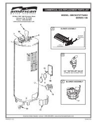
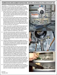
REPAIR PARTSKey No. Part Description1 Pipe Nipple2 Burner Tube3 Burner Head4 Thermocouple5 Pilot6 Draft Hood*7 Draft Hood Brace8 Inlet Tube9 Flue Baffle Assembly10 Anode Rod11 Cleanout Cover (Optional)12 Cleanout Gasket (Optional)13 Cleanout Screw (Optional)14 Inner Door15 Outer Door16 Gas Control Valve/Thermostat17 T & P Relief Valve18 Drain Valve19 Front Cover (optional)20 Pilot Tube (LP)21 Orifice*22 Fitting Breakaway*23 Metal Drain Pan*24 Instruction Manual* Not Shown.Now that you have purchased this water heater, should a needever exist for repair parts or service, simply contact the companyit was purchased from or direct from the manufacturer listed onthe rating plate on the water heater.Be sure to provide all pertinent facts when you call or visit.Selling prices will be furnished on request or parts willbe shipped at prevailing prices and you will be billedaccordingly.The model number of your Gas <strong>Water</strong> Heater will be found on therating place located above the gas control valve.DRAIN PAN 23NATURALPROPANEWHEN ORDERING REPAIR PARTS, ALWAYS GIVE THEFOLLOWING INFORMATION:3/4” T&P RELIEF VALVEAUTOMATIC, SELF-CLOSING TYPES• MODEL NUMBER• TYPE GAS (NATURAL OR PROPANE (L.P.)• SERIAL NUMBER• PART DESCRIPTIONTHIS IS A REPAIR PARTS LIST, NOT A PACKING LIST.2317APPROX.INSULATIonteMPthICKNESS PRESS. A = RELIEF> OR = 1.5” 150 LBS. 2.13” 210°F< 1.5” 150 LBS. 1.88” 210°FA
TROUBLESHOOTING GUIDELINESThese guidelines should be utilized by a qualified service technician.Problem Cause SolutionWATER LEAKSLEAKING T&P VALVESMELLY WATERPILOT WILL NOT LIGHTBURNER WILL NOTSTAY LITPILOT OUTAGENOT ENOUGHHOT WATERImproperly sealed, hot or cold supply connection, reliefvalve, drain valve, or thermostat threads.Leakage from other appliances or water lines.Condensation of flue products.Thermal expansion in closed water system.Improperly seated valve.High sulfate or mineral content in water supply.Bacteria in water supply.Gas control knob not positioned correctly.Main gas supply off.Thermocouple malfunction.Match not close to pilotThermocouple malfunction.Defective Gas Control.Dirty pilot burner.Thermocouple malfunction.Defective Gas Control.Thermocouple tip is not in contact with pilot flame.Heater not lit or thermostat not on.Thermostat set too low.Heater undersized.Low gas pressure.Incoming water is unusually cold.Leaking hot water pipes or fixtures.High temperature limit switch activated.Tighten threaded connections.Inspect other appliances near water heater.Refer to CONDENSATION.Install thermal expansion tank (DO NOT plug T&P valve).Check relief valve for proper operation(DO NOT plug T&P valve).Drain and flush heater thoroughly, then refill.Chlorinate or aerate water supply.Refer to LIGHTING INSTRUCTIONS.Turn on main gas shutoff valve.Replace pilot assembly and/or thermocouple.Locate pilot, move match closer.Replace pilot assembly and/or thermocouple.Replace Gas Control.Clean pilot assembly.Replace pilot assembly and/or thermocouple.Replace Gas Control.Insert thermocouple correctly.Refer to LIGHTING INSTRUCTIONS.Refer to TEMPERATURE REGULATION.Reduce hot water use.Contact your gas supplier.Allow more time for heater to re-heat.Have plumber check and repair leaks.Contact a service agency to determine cause.WATER TOO HOT Thermostat set too high. Refer to TEMPERATURE REGULATION.WATER HEATER SOUNDS Condensation dripping on burner. Refer to CONDENSATION.SIZZLING ORRUMBLINGSOOTINGVENT GAS ODORSSediment or calcium in bottom of heater tank.Improper combustion.Lack of supply air.Improperly installed vent piping.Downdraft.Poor combustion.Clean sediment from tank. Refer to DRAININGinstructions in Maintenance section of manual.No adjustment available. Contact a service agencyto determine cause.Contact a service agency to determine cause.24
NOTES25
NOTES26
NOTES27