Epoca Shoulder Arthroplasty System –Fracture ... - Osteosyntese
Epoca Shoulder Arthroplasty System –Fracture ... - Osteosyntese
Epoca Shoulder Arthroplasty System –Fracture ... - Osteosyntese

You also want an ePaper? Increase the reach of your titles
YUMPU automatically turns print PDFs into web optimized ePapers that Google loves.
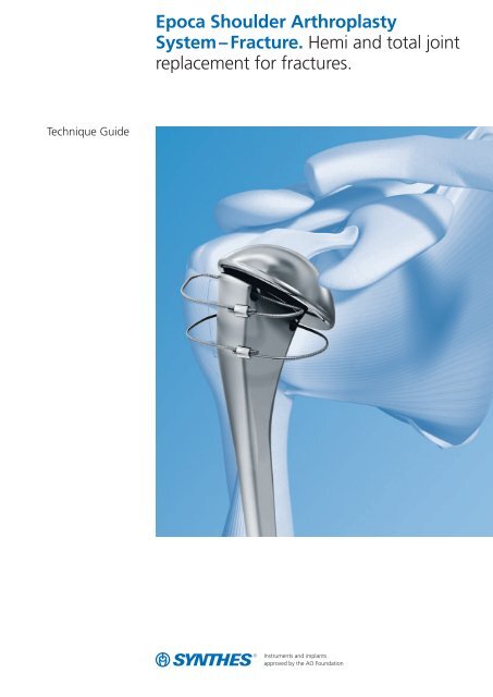
Technique Guide<strong>Epoca</strong> <strong>Shoulder</strong> <strong>Arthroplasty</strong><strong>System</strong> – Fracture. Hemi and total jointreplacement for fractures.
Table of ContentsIntroduction<strong>Epoca</strong> <strong>Shoulder</strong> <strong>Arthroplasty</strong> <strong>System</strong> 2AO Principles 4Indications and Contraindications 5Clinical Cases 6Surgical TechniquePreoperative Planning 8Patient Positioning 9Hemiarthroplasty for Fractures 10Implantation of a Glenoid Component 26Product InformationImplants 41Special Implants 45Instruments 46Bibliography56Image intensifier controlWarningThis description alone does not provide sufficient backgroundfor direct use of the product. Instruction by a surgeon experiencedin handling this product is highly recommended.Synthes 1
Indications and ContraindicationsIndications– Irreparable fractures of the proximal humerus– Posttraumatic conditions with advanced joint destruction– Failed previous osteosynthesisA glenoid component may be indicated in cases of cartilagedestruction or in case of an associated irreparable glenoidfracture where gleno-humeral stability is a concern.Contraindications– Infections, acute or chronic, local or systemic– Severe muscular, neurological or vascular deficiencies,which compromise the affected extremity– Destruction of bone or poor bone quality, which mayaffect stability of the implant– Any concomitant disease which may compromise thefunction of the implant– Any other pathology which needs treatment priorityConditions which can adversely affect joint replacementsuccess– Severe osteoporosis– Severe deformities, congenital dislocation– Allergic reaction to one of the materials used– Local tumors of the bone– <strong>System</strong>ic and metabolic disorders– History of infectious disease or falls– Drug or alcohol addiction and/or abuse– Obesity– High level of physical activity, involving shocks and shakingin which the prosthesis is subject to pounding and/orexcessive strains (e.g.: heavy physical labor, repetitive stressfrom sports, etc.)Synthes 5
Clinical Case 2Female patient, 65 years oldComminuted 4-part fracture with ischemic head andosteoporosis, left shoulderPreoperativeAP viewPostoperativeAP viewSynthes 7
Hemiarthroplasty for Fractures1Approach 1Standard deltopectoral approachStart the incision over the acromioclavicular joint and extendit 8 cm inferior over the anterior deltoid, lateral to the deltopectoralgroove. Alternatively, follow Langer’s skin tensionlines starting from the acromioclavicular joint.Open the fascia over the deltopectoral groove and identifythe cephalic vein. Retract the deltoid with the cephalic veinlaterally, and the pectoralis major medially.Incise the clavipectoral fascia.2Expose fractureIrrigate and remove the hematoma to expose the fracture.Check the vascularity of the humeral head and confirm thatjoint replacement is the optimal form of care.Pass stay sutures through the infraspinatus tendon to aidmanipulation of the greater tuberosity fragment.Expose and transect the biceps tendon in its extraarticularpath. Suture the biceps tendon to the pectoralis major fascia.Locate the split in the supraspinatus tendon induced bythe fracture. Enlarge the split in the supraspinatus tendon, asrequired, for access to the joint.Retrieve the fractured humeral head and set it aside for lateruse. Examine the glenoid. Consider ORIF or glenoid replacementif there is a relevant fracture of the glenoid or glenoidrim.1see Hertel et al., 331–338.10 Synthes <strong>Epoca</strong> <strong>Shoulder</strong> <strong>Arthroplasty</strong> <strong>System</strong> – Fracture Technique Guide
3Prepare tuberosities for later fixationPass stay-sutures through the subscapularis, supraspinatus,and infraspinatus tendons. Drill two holes in the greatertuberosity with a 2.0 mm drill bit. The two holes should beapproximately aligned with the medial and lateral perforationsof the prosthetic stem. Drill the holes close to the pointof transition from tendon to bone.Pass 1.0 mm cables through the drill holes. Alternatively,cerclage wires or high strength sutures can be used. Park thecables posteriorly, so that they do not interfere with the remainingsteps of the procedure.Expose the shaft by extending, adducting, and externallyrotating the humerus.4Determine stem heightMeasure the medial metaphyseal extension on the retrievedhead. This distance determines the precise height of thestem, i.e: how much the stem must protrude in respect tothe medial fracture line. Note the height in millimeters forlater reference.X mmSynthes 11
Hemiarthroplasty for Fractures5Select trial headInstrumentsE5114-40– Trial Heads, sizes 40 to 54E5114-54Osteotomize any remaining metaphyseal extensions to bettervisualize the head. Compare the retrieved humeral head withthe available trial heads. Choose the trial head that closelymatches the retrieved head. Save the humeral head for lateruse as bone graft.Note: If the AP and lateral radii differ, choose an intermediatetrial head size.12 Synthes <strong>Epoca</strong> <strong>Shoulder</strong> <strong>Arthroplasty</strong> <strong>System</strong> – Fracture Technique Guide
6Open medullary canal and determine retrotorsionInstruments359.221 Combined HammerE5115-1 Retrotorsion Bar 6.0 mmE5115-2 GoniometerE5112-6– Rasps, sizes 6 to 14E5112-14Probe and clean the medullary cavity with a sharp curette.Insert the size 6 rasp into the canal.To check the rotational alignment, insert the 6.0 mm retrotorsionbar into the threaded hole of the rasp. Hold the goniometeronto the lateral side of the retrotorsion bar. For thefirst rough adjustment, align the rasp to 25° retrotorsionwith reference to the axis of the forearm. This measurementreflects the median retrotorsion value for a normal population.11see Hertel et al., 331–338.Synthes 13
Hemiarthroplasty for FracturesHammer in the rasp until proper seating is obtained. If therasp penetrates too deep into the medullary cavity, use thenext larger rasp size until the correct prosthetic height is obtained.Should you have difficulties fully inserting the chosenrasp, remove additional bone along the medial endostealregion using a sharp curette. This will allow the rasp to seatand self-lock a few millimeters deeper.The pronounced calcar design provides the rasp and theimplants with self-centering, self-rotating and self-lockingcapabilities.Confirm the retrotorsion by cross-checking against the bicipitalgroove. The distance between the deepest point in thebicipital groove and the center line of the rasp should beapproximately 8 mm. 22see Hempfing et al., 460–4638mm14 Synthes <strong>Epoca</strong> <strong>Shoulder</strong> <strong>Arthroplasty</strong> <strong>System</strong> – Fracture Technique Guide
7Insert trial stemInstruments359.221 Combined HammerE5113-6– Trial Stems, sizes 6 to 14E5113-14E5115-2 GoniometerE5115-3 Slotted Hammer/ExtractorE5115-6 Retrotorsion Bar 3.0 mmAttach the inserter/extractor to the selected trial stem. Applycontrolled light blows to the top of the inserter/extractorwith the hammer. Hammer until the trial stem protrudesabove the shaft, as determined in step 4.To confirm the retrotorsion of the trial stem, insert the3.0 mm retrotorsion bar into the hole of the trial stem.Use the goniometer to measure the retrotorsion.Synthes 15
Hemiarthroplasty for Fractures8Attach trial eccenter discInstrumentsE5115-4/2Screwdriver <strong>Epoca</strong>, width across 2.0 mm,for Trial ImplantsE5117-20 Trial Eccenter DiscAttach the trial eccenter disc to the trial stem.Align the letter ‘A’ on the trial eccenter disc with the lateralline on the trial stem. This position reflects the normal (median)offset.Lock the trial eccenter disc using a 2.0 mm hex screwdriverin the proximal hole.16 Synthes <strong>Epoca</strong> <strong>Shoulder</strong> <strong>Arthroplasty</strong> <strong>System</strong> – Fracture Technique Guide
9Insert trial headInstrumentsE5114-40– Trial Heads, sizes 40 to 54E5114-54E5115-4/2E5115-4/3Screwdriver <strong>Epoca</strong>, width across 2.0 mm,for Trial ImplantsScrewdriver <strong>Epoca</strong>, width across 2.5 mm,for Trial ImplantsE5117-20 Trial Eccenter DiscUse a 2.0 mm hex screwdriver to back out the set screwsfrom the trial head in order to allow for correct seating. Becareful not to back out the set screws too far, as they mayfall out.Mount the trial head on the trial eccenter disc. Align the appropriatemarking on the trial head with the center line onthe trial stem (‘L’ for left humerus, ‘R’ for right humerus).Lock the trial head in position by tightening the anteriorset screw. Verify that the offset is appropriate for the patient’sanatomy. The ideal position is reached when the headmeets the medial calcar line with a continuous or unbrokenline, i.e.: no overhang or medial step-off.If the offset is not appropriate, adjust the anteroposteriorposition and/or the mediolateral offset. Loosen the trialeccenter disc with the 2.0 mm hex screwdriver. Use the2.5 mm hex screwdriver to rotate the trial eccenter disc untilthe desired head position is achieved.Synthes 17
Hemiarthroplasty for FracturesFor further adjustment, loosen the anterior set screw on thetrial head with the 2.0 mm hex screwdriver and manuallyrotate the trial head until the desired position is obtained.Lock the position by tightening the set screw.Note: The 2.0 mm hex screwdriver is used for locking andunlocking the set screws, the 2.5 mm hex screwdriver is usedonly to rotate the eccenter disc.Record the offset position of the trial head.18 Synthes <strong>Epoca</strong> <strong>Shoulder</strong> <strong>Arthroplasty</strong> <strong>System</strong> – Fracture Technique Guide
10Remove trial implantsInstruments359.221 Combined HammerE5115-3 Slotted Hammer/ExtractorE5115-4/2Screwdriver <strong>Epoca</strong>, width across 2.0 mm,for Trial ImplantsE5117-20 Trial Eccenter DiscOnce the offset position of the trial head is recorded, removethe trial head using the 2.0 mm hex screwdriver.Record the offset position of the trial eccenter disc.Important: Record the determined offset (number and letter)as these will be used to assemble the final implants.Remove the trial eccenter disc using the 2.0 mm hex screwdriver.Mount the inserter/extractor onto the trial stem.Lightly tap against the inserter/extractor to back out the trialstem.Note: To avoid possible damage to the thread, ensure thatthe inserter / extractor is fully threaded into the trial stem.Synthes 19
Hemiarthroplasty for Fractures11Assemble implantsInstrumentsE5115-5/1E5115-5/3E5115-5/4PressEccenter/ImpactorTorque Wrench for PressE5115-5/6– Holders for Press, sizes 6 to 14E5115-5/14Choose the stem holder that corresponds to the size of theshaft. Hold the half of the stem holder with two pegs withthe etched side facing up. Orient the distal end of the stemtoward the operator and slide the stem over the pegs. Slidethe other half of the stem holder over the pegs. This assemblyallows the stem to be firmly held in the press.Important: Ensure that the etched side of the stem holder isfacing up. Improper assembly may cause jamming.Position the eccenter on the stem. Align the letter recordedduring trial implantation (step 9) with the center line of thestem. Place the assembly in the press and place the eccenter/impactorover the eccenter. Using the torque wrench,turn the handle of the press clockwise until a click is heard,signifying the positive engagement of the eccenter and thestem.Turn the torque wrench counterclockwise and remove theeccenter/impactor. Remove the stem-eccenter assembly fromthe press.20 Synthes <strong>Epoca</strong> <strong>Shoulder</strong> <strong>Arthroplasty</strong> <strong>System</strong> – Fracture Technique Guide
Place the head on the stem assembly. Align the recordedoffset position with the lateral marking on the implant or thecontact line between the two halves of the stem holder.Place the head and the stem eccenter assembly in the press.Compress components by turning the torque wrench clockwiseuntil a click is heard.Remove the implant from the press. Remove the stem holderand check for adequate seating of the head and the eccenter.Note: No visible gap should be present between the base ofthe head and the humeral stem.Synthes 21
Hemiarthroplasty for Fractures12Implant prosthesisChoose the final implantation method according to the typeof stem being used (cemented/uncemented).Instruments359.221 Combined HammerE5115-2 GoniometerE5115-6 Retrotorsion Bar 3.0 mmE5115-7 ImpactorMount the plastic liner onto the head impactor.12aFinal implantation for cemented stemsDo a final irrigation of the medullary canal. Insert a cementrestrictor to prevent excess cement from flowing into thedistal humerus.Place a vent tube in the medullary canal. Dry the cavity.Inject cement into the canal. Remove the vent tube whilethe cement is being injected.Ensure that the implant assembly is clean before inserting it.Check the final retrotorsion using the 3.0 mm retrotorsionbar.Remove any excess bone cement from the collar regionbefore it sets to provide room for bone graft.Fill the collar region with autogenous bone graft harvestedfrom the retrieved head to improve healing betweentuberosities and shaft.Note: Follow the manufacturer’s instructions for preparation,injection and setting of the bone cement.Insert the implant, first manually, then using the head impactoruntil the predetermined anatomic prosthetic height isreached. The implant will be protruding as defined in steps 4and 7 of this procedure.22 Synthes <strong>Epoca</strong> <strong>Shoulder</strong> <strong>Arthroplasty</strong> <strong>System</strong> – Fracture Technique Guide
12bFinal implantation for pressfit, cementless stemsIntroduce the prosthesis into the medullary canal. To confirmproper placement and orientation of the implant, use the3.0 mm retrotorsion bar and the goniometer to recheckthe retrotorsion. Lightly tap on the head impactor with thehammer until the implant is fully seated.The position must correspond to the predeterminedanatomic prosthetic height. If the implant’s position is toohigh, more bone rasping along the medial cortex is required.If the implant finds its stable position in a location that is toodistal, use a shaft one size larger. Alternatively, the smallershaft can be stabilized in the correct position using bonecement.Note: The implant must protrude as defined in steps 4 and 7.Fill the collar region with autogenous bone graft harvestedfrom the retrieved head to improve healing betweentuberosities and shaft.Synthes 23
Hemiarthroplasty for Fractures13Reduction and stable fixation of the tuberositiesInstrumentsE5014-04 Crimping PliersE5014-05 Wire Tightener for CerclageE5014-06 Cutting Pliers for CerclageWith the humeral head still in the anteriorly dislocated position,pass the cables that were initially placed in step 3through the greater tuberosity/rotator cuff junction throughthe medial and lateral perforations of the stem.Reduce the joint i.e. the prosthetic head to the glenoid andto the greater tuberosity. Pass the cable through the lessertuberosity. Reduce the lesser tuberosity to the prosthesis.Use sutures to readapt the split in the rotator cuff to obtainpreliminary reduction of the tuberosities. Avoid over-reductionof the greater tuberosity, especially in a distal direction.The most medial insertion line of the supraspinatus must beflush with the edge of the prosthetic head, not distal to it.Fill any void under the tuberosities with cancellous bonegraft harvested from the retrieved head. Use absorbablesutures for preliminary reduction and adaptation of therelevant fragments.24 Synthes <strong>Epoca</strong> <strong>Shoulder</strong> <strong>Arthroplasty</strong> <strong>System</strong> – Fracture Technique Guide
Embrace and compress the tuberosities against the rectangularcross section of the shaft to obtain rotational stability.Tension the cables with a tensioning device as far as possiblewithout deforming the tuberosities. When using embracingcables, additionally devascularizing vertical sutures betweenshaft and tuberosities are not necessary. The use of embracingcables requires a tenotomy and tenodesis of the bicepstendon.Synthes 25
Implantation of a GlenoidComponentA glenoid component may be indicated in cases where thereis associated cartilage damage to the glenoid or where thereare irreparable glenoid fractures in which gleno-humeral stabilityis a concern.Note: The size of the glenoid implant is determined by thesize of the humeral head component.1Approach and exposureAdequate exposure of the glenoid is essential for implantation.Exposure must permit the use of straight instrumentssuch as reamers and drill bits. In fractures, exposure of theglenoid generally follows the space between the tuberosities.Introduce a tear-drop ring retractor (or another instrumentsuch as a Fukuda Ring Retractor) to displace the greatertuberosity in a posterior and inferior direction.Remove any remnants of the cartilage.26 Synthes <strong>Epoca</strong> <strong>Shoulder</strong> <strong>Arthroplasty</strong> <strong>System</strong> – Fracture Technique Guide
2Locate center pointLocate the true center of the glenoid, which is slightly inferiorto the midpoint of Saller’s line (vertical line dividing theglenoid into anterior and posterior halves). This is the slippagepoint of the humeral head during concentric motion.Synthes 27
Implantation of a Glenoid Component3Ream glenoidInstruments292.260 Kirschner Wire 2.5 mm, length 280 mmE5211-2 Guide Extension, rigidE5211-3 Wrench, width across 10 (2)E5211-4LE5211-4RDrill Guide, leftDrill Guide, rightE5211-28 Reamer 28 mm for GlenoidE5211-32 Reamer 32 mm for GlenoidThe shape of the drill guide matches the shape of the glenoidimplant. Determine the desired anatomic position of theglenoid implant by placing the drill guide (left or right) onthe glenoid. The central hole of the drill guide should coverthe center point located in step 2. Hold the drill guide in thecorrected position. Introduce the 2.5 mm K-wire and recheckthe positioning.28 Synthes <strong>Epoca</strong> <strong>Shoulder</strong> <strong>Arthroplasty</strong> <strong>System</strong> – Fracture Technique Guide
Assemble the smallest reamer (28 mm) onto the cannulatedextension using 10 mm wrenches. Couple the assembly topower equipment using a Jacobs chuck. If there is sufficientexposure, place the reamer assembly over the K-wire, positionthe reamer firmly against the glenoid, and ream.If there is not enough exposure to be able to slide the reamerover the K-wire, remove the K-wire. Place the reamer assemblyon the glenoid, then reintroduce the K-wire through theassembly into the previously drilled central hole, and ream.OptionAlternatively, free-hand reaming is possible without the useof guide wires. The reamer produces a uniformly concavesurface, which is independent of the size of the glenoid.Ream clockwise at high speed with steady light pressure.Windows in the reamer allow for visualization of the glenoidand the extent of reaming. During the reaming process, correctthe retro- or anteversion while preserving as much densesubchondral bone as possible.Warning: Too much axial pressure on the reamer whilereaming weak or osteopenic bone may lead to overreaming.For larger glenoid sizes (52 mm – 58 mm), continue reamingwith the 32 mm reamer to gain superior and inferior extensionof the prepared surface.Synthes 29
Implantation of a Glenoid Component4Prepare for trial glenoidInstruments292.260 Kirschner Wire 2.5 mm, length 280 mmE5211-4LE5211-4RE5211-6KE5211-6LDrill Guide, leftDrill Guide, rightDrill Bit 7.4 mm, length 150 mm,for Glenoid and Shell ScrewDrill Bit 7.4 mm, length 200 mm,for Glenoid and Shell ScrewIf the K-wire has been removed, reinsert it. Reintroduce thedrill guide (left or right) over the K-wire. Rotate the drillguide until anatomic alignment is obtained.Note: Use the insertion point of the biceps tendon as alandmark to determine the alignment of the longitudinal axisof the glenoid. It is recommended to position the inferiorhole slightly posterior and the superior hole slightly anteriorto Saller’s Line. Bone stock is typically better in this location.Using the shorter (150 mm) drill bit, drill the distal hole first.The depth of the drill hole depends on the planned implanttype.30 Synthes <strong>Epoca</strong> <strong>Shoulder</strong> <strong>Arthroplasty</strong> <strong>System</strong> – Fracture Technique Guide
4aCemented all-poly glenoidFor cemented all-poly glenoid, drill to a depth of 19 mm.19 mm4bHybrid glenoid with shell screwsFor shell screw 10 mm, drill to a depth of 21 mm.For shell screw 15 mm, drill to a depth of 26 mm.For shell screw 20 mm, drill to a depth of 31 mm.The smallest (10 mm) shell screw is the standard implant.Longer versions are typically used when bone defects such ascomminuted anterior glenoid rim fractures require bridging.21 mm4cPressfit metalback glenoidFor pressfit metalback glenoid, drill to a depth of 21 mm.21 mmRemove the Jacobs chuck but leave the drill bit in situ to stabilizethe drill guide while drilling the second hole.Prepare the proximal hole using the long drill bit (200 mm).Remove the drill bits, K-wire and drill guide.Synthes 31
Implantation of a Glenoid Component5Introduce trial glenoidInstrumentsE5211-8EHolding Forceps for Trial GlenoidE5213-42– Trial Glenoids, size 42 to 54E5213-54Select the trial glenoid that matches the sizeof the humeral head.Trial GlenoidsHead size 40 42 44 46 48 50 52 54Trial size 40/42 40/42 44/46 44 /46 48/50 48/50 52/54 52/54Art. No. E5213–42 E5213–42 E5213–46 E5213–46 E5213–50 E5213–50 E5213–54 E5213–5432 Synthes <strong>Epoca</strong> <strong>Shoulder</strong> <strong>Arthroplasty</strong> <strong>System</strong> – Fracture Technique Guide
Use the trial glenoid holding forceps to insert the trial glenoid.Check the fit of the trial implant and ensure that therear surface of the trial fits firmly to the reamed surface ofthe glenoid. If not, additional reaming of the glenoid is required.Alternatively, gaps may be filled with autogenousbone graft.In case of a comminuted anterior glenoid rim fracture, theglenoid implant is stabilized by 15 or 20 mm shell screwswhile the fracture fragment can be reduced and fixed with asimple osteosuture.Note: A simple suture loop to readapt the radial labral tearoccurring at the 2 o’clock position is often sufficient.Synthes 33
Implantation of a Glenoid Component6Implant glenoid componentInstruments359.221 Combined HammerE5211-8 Holding Forceps for GlenoidF017-4.5F017-2.5Screwdriver, hexagonal, width across4.5 mmScrewdriver, hexagonal, width across2.5 mmE5211-10 Glenoid ImpactorE5221-1 Metalback ImpactorE5221-2 Drill Sleeve 2.5 (2)E5221-3 Drill Bit 2.5 mmEnsure that the plastic impactor liner is mounted on theglenoid impactor.Cemented all-poly glenoidClean and dry the drilled cavities. Consider using a suctiondevice introduced through the base of the coracoid processto evacuate undesired fluids. Introduce a small amount ofbone cement (methylmethacrylate) into the two drilled cavities(0.15 ml in each cavity) using a 1 ml syringe.Note: Avoid overflow of the cement onto the faceplate ofthe glenoid as this will lead to a thin and brittle cement layer.Consult the manufacturer’s instructions for proper bone cementusage.34 Synthes <strong>Epoca</strong> <strong>Shoulder</strong> <strong>Arthroplasty</strong> <strong>System</strong> – Fracture Technique Guide
Mount the glenoid implant on the special holding forcepsand introduce the implant in the correct orientation (the narrowpart facing up). Introduce the glenoid implant and seat itinto its final position with light hammer taps on the glenoidimpactor.Synthes 35
Implantation of a Glenoid ComponentHybrid glenoid (with shell screws)Insert the previously selected shell screws (see step 4) withthe long 4.5 mm hex screwdriver. The shell screw should beslightly below the surface of the bone. Introduce a smallamount of bone cement (0.13 ml methylmethacrylate) intoeach shell screw using a 1 ml syringe.Note: Avoid overflow of the cement onto the faceplate ofthe glenoid, as this will lead to a thin and brittle cementlayer. Consult the manufacturer’s instructions for bone cementusage.36 Synthes <strong>Epoca</strong> <strong>Shoulder</strong> <strong>Arthroplasty</strong> <strong>System</strong> – Fracture Technique Guide
Place the glenoid implant in position using the glenoid holdingforceps. Set the glenoid implant into place using thehammer and glenoid impactor.Synthes 37
Implantation of a Glenoid ComponentPressfit metalback glenoidPlace the metalback glenoid implant in position using themetalback impactor. Lightly tap the glenoid implant intoplace using the hammer and glenoid impactor.Note: The metalback glenoid can be fixed with 3.5 mm cortexscrews at the bottom of the pegs for additional stability.OptionAdditional screw fixation depends upon surgeons’ intraoperativejudgment and preference. For this purpose, a specialaiming drill guide is available. Introduce the cylindrical drillguide in the cylindrical metal-back peg and drill with a2.5 mm drill bit. Measure the screw length and introduce astandard 3.5 mm cortical screw.38 Synthes <strong>Epoca</strong> <strong>Shoulder</strong> <strong>Arthroplasty</strong> <strong>System</strong> – Fracture Technique Guide
Place the glenoid implant in position using the glenoid holdingforceps. Set the glenoid implant into place using thehammer and glenoid impactor.Synthes 39
Implantation of a Glenoid Component7Complete implantation of humeral componentRemove the humeral retractors and expose the proximalhumerus. Complete implantation of a standard humeralcomponent.40 Synthes <strong>Epoca</strong> <strong>Shoulder</strong> <strong>Arthroplasty</strong> <strong>System</strong> – Fracture Technique Guide
Implants(all Implants are sterile packed)Humeral Stem, uncemented– Titanium alloy (TAV) with Ti+HA coating– Also for Nickel sensitive PatientsArt. No. Size (mm) Length (mm)5528-6/11 6 1155528-8/12 8 1205528-10/12 10 1255528-12/13 12 1305528-14/13 14 135Humeral Stem, cemented– Stainless SteelArt. No. Size (mm) Length (mm)5614-6/11 6 1155614-8/12 8 1205614-10/12 10 1255614-12/13 12 1305614-14/13 14 135Synthes 41
ImplantsTitanium Eccenter– Titanium alloy (TAV)Art. No. Usage5413-20/5 StandardHead– Stainless SteelArt. No. (mm) Height (mm)5311–40/15 40 15.005311–42/15 42 15.755311–44/16 44 16.505311–46/17 46 17.255311–48/18 48 18.005311–50/18 50 18.755311–52/19 52 19.505311–54/20 54 20.255311–56/21 56 21.00 optional5311–58/22 58 21.75 optionalGlenoid– UHMW polyethylene– Can be used as stand alone component or in combinationwith Shell Screws or Metalback componentArt. No. For Head (mm)5213–42 40 and 425213–44 445213–46 465213–48 485213–50 505213–52 525213–54 545213–56 56 optional5213–58 58 optional42 Synthes <strong>Epoca</strong> <strong>Shoulder</strong> <strong>Arthroplasty</strong> <strong>System</strong> – Fracture Technique Guide
Shell Screws for hybrid Glenoid– Titanium alloy (TAV)– For use with Polyethylene Glenoid componentArt. No. Length (mm) Glenoid5114-9/10 10 5213-42 to 5213-585114-9/15 15 5213-42 to 5213-585114-9/20 20 5213-42 to 5213-58Metalback component for cementless Glenoid– Titanium alloy (TAV)– For use with Polyethylene GlenoidArt. No. Size Glenoid5118-42 40 + 42 5213-425118-46 44 + 46 5213-44 / 5213-465118-50 48 + 50 5213-48 / 5213-505118-54 52 + 54 5213-52 / 5213-54Cortex Screw 3.5 mm– Optional for use with Metalback GlenoidArt. No. Length (mm)404.010S 10404.012S 12404.014S 14404.016S 16404.018S 18404.020S 20404.022S 22404.024S 24404.026S 26404.028S 28404.030S 30Synthes 43
ImplantsTubercable– Stainless Steel– For Tubercula Refixation in Trauma surgeryArt. No.9014-6/50 1.0 (mm)44 Synthes <strong>Epoca</strong> <strong>Shoulder</strong> <strong>Arthroplasty</strong> <strong>System</strong> – Fracture Technique Guide
Special Implants(all Implants are sterile packed)Head for Allergy Patients– Stainless Steel, with TiNb coatingArt. No. (mm) Height (mm)5321–40/15 40 15.005321–42/15 42 15.755321–44/16 44 16.505321–46/17 46 17.255321–48/18 48 18.005321–50/18 50 18.755321–52/19 52 19.505321–54/20 54 20.255321–56/21 56 21.00 optional5321–58/22 58 21.75 optionalStem for Allergy Patients, sterile– See Humeral Stem, uncemented (Titanium alloy TAV)– Art. No. 5528-6/11 to 5528-14/13Synthes 45
Instruments01.401.030 Instruments <strong>Epoca</strong> Humerus68.401.037 Vario Case for Humeral Stem Instruments689.507 Lid for Vario Case359.221 Combined HammerE5112-1 Starter Rasp <strong>Epoca</strong>, size 6E5115-1 Retrotorsion Bar <strong>Epoca</strong> 6.0 mmE5115-2 Goniometer <strong>Epoca</strong>46 Synthes <strong>Epoca</strong> <strong>Shoulder</strong> <strong>Arthroplasty</strong> <strong>System</strong> – Fracture Technique Guide
E5112-6 Rasp <strong>Epoca</strong>, size 6E5112-8 Rasp <strong>Epoca</strong>, size 8E5112-10 Rasp <strong>Epoca</strong>, size 10E5112-12 Rasp <strong>Epoca</strong>, size 12E5112-14 Rasp <strong>Epoca</strong>, size 14E5115-3 Slotted Hammer/Extractor <strong>Epoca</strong>E5113-6 Trial Stem <strong>Epoca</strong>, size 6E5113-8 Trial Stem <strong>Epoca</strong>, size 8E5113-10 Trial Stem <strong>Epoca</strong>, size 10E5113-12 Trial Stem <strong>Epoca</strong>, size 12E5113-14 Trial Stem <strong>Epoca</strong>, size 14E5115-6 Retrotorsion Bar <strong>Epoca</strong> 3.0 mmE5115-4/2Screwdriver <strong>Epoca</strong>, width across 2.0 mm,for Trial ImplantsE5115-4/3Screwdriver <strong>Epoca</strong>, width across 2.5 mm,for Trial ImplantsSynthes 47
InstrumentsE5117-20 Trial Eccenter Disc <strong>Epoca</strong>E5114-40 Trial Head <strong>Epoca</strong>, size 40E5114-42 Trial Head <strong>Epoca</strong>, size 42E5114-44 Trial Head <strong>Epoca</strong>, size 44E5114-46 Trial Head <strong>Epoca</strong>, size 46E5114-48 Trial Head <strong>Epoca</strong>, size 48E5114-50 Trial Head <strong>Epoca</strong>, size 50E5114-52 Trial Head <strong>Epoca</strong>, size 52E5114-54 Trial Head <strong>Epoca</strong>, size 54E5114-56 Trial Head <strong>Epoca</strong>, size 56 (optional)E5114-58 Trial Head <strong>Epoca</strong>, size 58 (optional)E5115-8/38E5115-8/44E5115-8/48Humeral Cover <strong>Epoca</strong> 38 mm,for Trial StemHumeral Cover <strong>Epoca</strong> 44 mm,for Trial StemHumeral Cover <strong>Epoca</strong> 48 mm,for Trial StemE5115-7 Impactor <strong>Epoca</strong>48 Synthes <strong>Epoca</strong> <strong>Shoulder</strong> <strong>Arthroplasty</strong> <strong>System</strong> – Fracture Technique Guide
Press <strong>Epoca</strong>68.401.032 Vario Case for Press <strong>Epoca</strong>689.507 Lid for Vario CaseE5115-5/1Press <strong>Epoca</strong>E5115-5/6E5115-5/8E5115-5/10E5115-5/12E5115-5/14Holder <strong>Epoca</strong> for size 6, for PressHolder <strong>Epoca</strong> for size 8, for PressHolder <strong>Epoca</strong> for size 10, for PressHolder <strong>Epoca</strong> for size 12, for PressHolder <strong>Epoca</strong> for size 14, for PressE5115-5/3Eccenter/Impactor <strong>Epoca</strong>E5115-5/4Torque Wrench <strong>Epoca</strong>, for PressSynthes 49
Instruments01.401.033 Instruments for Glenoids <strong>Epoca</strong>68.401.033 Vario Case for Instruments forGlenoids <strong>Epoca</strong>689.507 Lid for Vario CaseE5211-4LE5211-4RDrill Guide <strong>Epoca</strong>, leftDrill Guide <strong>Epoca</strong>, right292.260 Kirschner Wire 2.5 mm,length 280 mm (2)E5211-2 Guide Extension <strong>Epoca</strong>, rigid50 Synthes <strong>Epoca</strong> <strong>Shoulder</strong> <strong>Arthroplasty</strong> <strong>System</strong> – Fracture Technique Guide
E5211-3 Wrench <strong>Epoca</strong>, width across 10(2)E5211-28 Reamer <strong>Epoca</strong> 28 mm, for GlenoidE5211-32 Reamer <strong>Epoca</strong> 32 mm, for GlenoidE5211-6LDrill Bit <strong>Epoca</strong> 7.4 mm, length 200 mm,for Glenoid and Hollow ScrewE5211-6KDrill Bit <strong>Epoca</strong> 7.4 mm, length 150 mm,for Glenoid and Hollow ScrewE5211-8EHolding Forceps <strong>Epoca</strong> for Trial GlenoidSynthes 51
InstrumentsE5213-42 Trial Glenoid <strong>Epoca</strong>, size 42E5213-46 Trial Glenoid <strong>Epoca</strong>, size 46E5213-50 Trial Glenoid <strong>Epoca</strong>, size 50E5213-54 Trial Glenoid <strong>Epoca</strong>, size 54F017-4.5Screwdriver <strong>Epoca</strong>, hexagonal,width across 4.5 mmE5221-1 Metalback Impactor <strong>Epoca</strong>52 Synthes <strong>Epoca</strong> <strong>Shoulder</strong> <strong>Arthroplasty</strong> <strong>System</strong> – Fracture Technique Guide
E5211-8 Holding Forceps <strong>Epoca</strong> for GlenoidE5211-10 Glenoid Impactor <strong>Epoca</strong>E5221-2 Drill Sleeve <strong>Epoca</strong> 2.5 (2)E5221-3 Drill Bit <strong>Epoca</strong> 2.5 mmF017-2.5Screwdriver, hexagonal, <strong>Epoca</strong>,width across 2.5 mmSynthes 53
InstrumentsCerclage InstrumentsE5014-04 Crimping PliersE5014-05 Wire Tightener for CerclageE5014-06 Cutting Pliers for Cerclage54 Synthes <strong>Epoca</strong> <strong>Shoulder</strong> <strong>Arthroplasty</strong> <strong>System</strong> – Fracture Technique Guide
Synthes 55
BibliographyStanley Hoppenfeld and Piet deBoer, Surgical Exposures inOrthopaedics–The Anatomic Approach, Third Edition, 2003,pp. 2–8.Hertel R, Knothe U, Ballmer FT. Geometry of the proximalhumerus and implications for prosthetic design. J <strong>Shoulder</strong>Elbow Surg. 2002;11(4):331-8.Hempfing A, Leunig M, Ballmer FT, Hertel R. Surgical landmarksto determine humeral head retrotorsion for hemiarthroplastyin fractures. J <strong>Shoulder</strong> Elbow Surg.2001;10(5):460-3.56 Synthes <strong>Epoca</strong> <strong>Shoulder</strong> <strong>Arthroplasty</strong> <strong>System</strong> – Fracture Technique Guide
Ö036.000.962öABaäSynthes GmbHEimattstrasse 3CH-4436 Oberdorfwww.synthes.com Presented by:0123036.000.962 SE_092747 AB 30070099 © 04/2008 Synthes, Inc. or its affiliates All rights reserved Synthes and <strong>Epoca</strong> are trademarks of Synthes, Inc. or its affiliates