

Adding TXVs to Voyager units - HVAC.Amickracing
Adding TXVs to Voyager units - HVAC.Amickracing
Adding TXVs to Voyager units - HVAC.Amickracing

You also want an ePaper? Increase the reach of your titles
YUMPU automatically turns print PDFs into web optimized ePapers that Google loves.
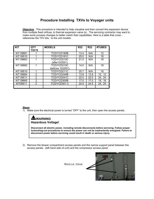
Procedure Installing <strong>TXVs</strong> <strong>to</strong> <strong>Voyager</strong> <strong>units</strong>Objective : This procedure is intended <strong>to</strong> help visualize and then convert the expansion devicefrom multiple fixed orifices, <strong>to</strong> thermal expansion valve (s) . The servicing contrac<strong>to</strong>r may want <strong>to</strong>make some process changes <strong>to</strong> better match their capabilities. Here is a table that cross -references the TXV kits, <strong>to</strong> the unit models .KIT QTY MODELS R22 R22 #TUBESTXV’SKIT 09661 1 TCD/YCD180B 13.4 N/A 12KIT 09510 1 TCD/YCD181C 25.0 N/A 16KIT 09663 1 TCD/YCD210C 21.0 N/A 16(after10/2001)KIT 09662 1 TCD/YCD210C 14.0 N/A 18(befrore 10/2001)KIT 09510 1 TCD/YCD211C 25.7 N/A 16KIT 09664 2 TCD/YCD240B 13.8 13.8 12, 12KIT 09511 2 TCD/YCD241C 22.0 22.0 24, 24KIT 09665 2 TCD/YCD300B 17.0 17.0 18, 18KIT09511 2 TCD/YCD301 C 24.5 24.5 24, 24Steps:1) Make sure the electrical power is turned “OFF” <strong>to</strong> the unit, then open the access panels.WARNINGHazardous Voltage!Disconnect all electric power, including remote disconnects before servicing. Follow properlockout/tag-out procedures <strong>to</strong> ensure the power can not be inadvertently energized. Failure <strong>to</strong>disconnect power before servicing could result in death or serious injury.2) Remove the blower compartment access panels and the narrow support panel between theaccess panels . (left hand side of unit) and the compressor access panel.
3) Recover the refrigerant. (Some models will have 2 circuits <strong>to</strong> recover, other 1 circuit)4) Each circuit can now be cut away ….the liquid header tube is cut, at the <strong>to</strong>p of the tube ,before the first orifice tube . Then, cut each orifice tube about 4” from the header tube(orifice is located internal <strong>to</strong> this tube section). Note : If both circuits are being removed, markthe tubes for later identification5) The rough cuts can now be trimmed with a small tubing cutter .6) Position the TXV assembly <strong>to</strong> the liquid tube and bend and group the feeder tubes (preparingthem for brazing <strong>to</strong> the individual circuits previously cut).
7) Route and bend the individual feeder tubes <strong>to</strong> the cut tubes feeding the evap coil circuits.Check <strong>to</strong> make sure the connections are not cross-circuited. The TXV feeder tubes are 3/16”dia and should be inserted about 1 “ in<strong>to</strong> the existing circuit tubes. The 3/8 existing tubes willrequire some crimping for a neat braze joint. Braze the feeder tube connections using thenitrogen purge.8) To connect the equalizer line (s) <strong>to</strong> the suction line , drill 1/8” dia hole near the upper portionof the suction line. Note: If the nitrogen purge pressure inside the suction line is between 50<strong>to</strong> 100 psig, the copper chips will be blown <strong>to</strong> the outside of the tube. Take care not <strong>to</strong> crosscircuit the equalizer lines.9) The TXV sensing bulbs are <strong>to</strong> be located just <strong>to</strong> the right of the equalizer line connections onthe suction line. Secure the bulbs at the 9:00 O’clock position. Pull the suction line insulationback in<strong>to</strong> position and make sure the sensing bulb is insulated, using the additional materialprovided.
10) The kit has a new filter-drier(s) s that can be used <strong>to</strong> replace the existing filter-driers.11) With all weld joints complete, a leak test can performed on the all the new connections.12) The system is now ready for evacuating and recharging. Recommend recharging with newrefrigerant. Refrigerant charge information is shown in the table below. If the unit nameplatehas different information, recharge <strong>to</strong> the unit nameplate information.13) The expansion valves are NOT preset and after the unit has run for 20 minutes, with bothcompressors running, start adjusting the superheat <strong>to</strong> obtain 10 <strong>to</strong> 15 degrees superheat.(CCW increases flow and reduces the superheat…. Example - 75 psig suction pressure has44 deg saturated temperature and a 56deg suction line temperature yields 12 degsuperheat. )Note : Reinstall the access panels and before re-applying the electrical power .


