platu 25 class rules 2011
platu 25 class rules 2011
platu 25 class rules 2011

Create successful ePaper yourself
Turn your PDF publications into a flip-book with our unique Google optimized e-Paper software.
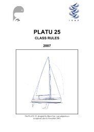
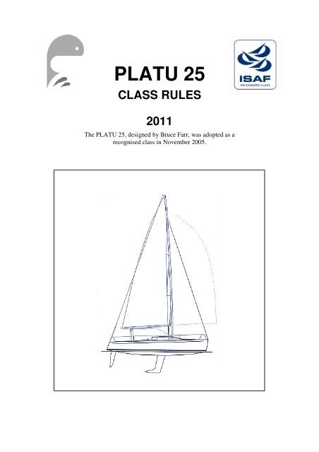
PLATU <strong>25</strong>CLASS RULES<strong>2011</strong>The PLATU <strong>25</strong>, designed by Bruce Farr, was adopted as arecognised <strong>class</strong> in November 2005.
INDEXPART I – ADMINISTRATIONSection A – GeneralA.1 Language ......................................A.2 Abbreviations ...............................A.3 Authorities and Responsibility......A.4 Administration of the Class ..........A.5 ISAF Rules ...................................A.6 Class Rules Variations .................A.7 Class Rules Amendments .............A.8 Class Rules Interpretation ............A.9 International Class Fee andISAF Building Plaque ..................A.10 Sail Numbers ................................A.11 Hull Certification .........................A.12 Initial Hull Certification ...............A.13 Validity of Certificate ..................A.14 Hull Re-Certification ....................A.15 Retention of CertificationDocumentation .............................Section B – Boat EligibilityB.1 Class Rules and Certification .......B2 Class Association Markings .........PART II – REQUIREMENTS ANDLIMITATIONSSection C – Conditions for RacingC.1 General .........................................C.2 Crew .............................................C.3 Personal Equipment .....................C.4 Advertising ...................................C.5 Portable Equipment ......................C.6 Boat ..............................................C.7 Hull ...............................................C.8 Hull Appendages...........................C.9 Rig ................................................C.10 Sails ..............................................Section D– HullD.1 Parts ..............................................D.2 General .........................................D.3 Hull Shell .....................................D.4 Deck .............................................D.5 Interior of Hull .............................D.6 Assembled Hull ............................Section E – Hull AppendagesE.1 Parts ..............................................E.2 General .........................................E.3 Keel ..............................................E.4 Rudder Blade, Rudder Stockand Tiller ......................................Section F – RigF.1 Parts ..............................................F.2 General .........................................F.3 Mast ..............................................F.4 Boom ............................................F.5 Spinnaker Pole .............................F.6 Standing Rigging .........................F.7 Running Rigging ..........................Section G – SailsG.1 Parts ..............................................G.2 General .........................................G.3 Mainsail ........................................G.4 Headsail ........................................G.5 Spinnaker .....................................PART III – APPENDICES.......................................................Platu <strong>25</strong> Class Rules <strong>2011</strong> 2
INTRODUCTIONPLATU <strong>25</strong> hulls and hull appendages are manufacturer controlled; rigs and sails are measurementcontrolled.PLATU <strong>25</strong> hulls and hull appendages shall only be manufactured by builders in the <strong>class</strong> <strong>rules</strong>referred to as licensed manufacturers. Equipment is required to comply with the InternationalPLATU <strong>25</strong> Building Specification and is subject to an ISAF approved manufacturing controlsystem.PLATU <strong>25</strong> hulls, hull appendages, rigs and sails may, after having left the manufacturer, only bPealtered to the extent permitted in Section C of the <strong>class</strong> <strong>rules</strong>.Owners and crews should be aware that compliance with <strong>rules</strong> in Section C is NOT checked as partof the certification process.Rules regulating the use of equipment during a race are contained in Section C of these <strong>class</strong> <strong>rules</strong>,in ERS Part I and in the Racing Rules of Sailing.This introduction only provides an informal background and the International PLATU <strong>25</strong> ClassRules proper begin on the next page.Platu <strong>25</strong> Class Rules <strong>2011</strong> 3
PART I – ADMINISTRATIONSection A – GeneralA.1 LANGUAGEA.1.1 The official language of the <strong>class</strong> is English and in case of dispute over translation theEnglish text shall prevail.A.1.2 The word “shall” is mandatory and the word “may” is permissive.A.1.3 The term “permanently fastened” shall mean unable to be removed with simple tools, orfixed with glue or rivets.A.1.4. The term “permanent” for limit marks shall mean unable to be removed and repositionedwithout destroying them.A.2 ABBREVIATIONSA.2.1 ISAF International Sailing FederationMNA ISAF Member National AuthorityIPCA International Platu <strong>25</strong> Class AssociationFYD Farr Yacht DesignNCA National Class AssociationERS Equipment Rules of SailingRRS Racing Rules of SailingA.3 AUTHORITIES AND RESPONSIBILITIESA.3.1 The international authority of the <strong>class</strong> is the ISAF which shall co-operate with the IPCAin all matters concerning these <strong>class</strong> <strong>rules</strong> according to IPCA proposals.A.3.2 Notwithstanding anything contained herein, the certification authority has the authorityto withdraw a certificate and shall do so on the request of the ISAF.A.3.3 No legal responsibility with respect to these <strong>class</strong> <strong>rules</strong>, or accuracy of measurement, restswith :the ISAFthe MNAthe IPCAan NCAthe Certification Authority, CAan official measurerNo claim arising from these <strong>class</strong> <strong>rules</strong> can be entertainedA.4 ADMINISTRATION OF THE CLASSA.4.1 ISAF has delegated its administrative functions of the <strong>class</strong> to IPCA. The IPCA maydelegate part or all of its functions, as stated in these <strong>class</strong> <strong>rules</strong>, to an NCAA.5 ISAF RULESA.5.1 These <strong>class</strong> <strong>rules</strong> shall be read in conjunction with the ERS.A.5.2 Except where used in headings, when a term is printed in “bold” the definition in the ERSapplies and when a term is printed in “italics” the definition in the RRS applies.Platu <strong>25</strong> Class Rules <strong>2011</strong> 4
A.6 CLASS RULES VARIATIONSA.6.1 At World, Continental or Regional Championships the notice of race and sailinginstructions may vary these <strong>class</strong> <strong>rules</strong> only with the agreement of IPCA and the ISAFA.6.2 At National events the notice of race and sailing instructions may vary these <strong>class</strong> <strong>rules</strong>only with the agreement of the NCA and the MNAA.6.3. The notice of race or sailing instruction may require additional or alternative safetyequipment.A.6.4 At Class events, these <strong>class</strong> <strong>rules</strong> shall not be varied by the notice of race and sailinginstructions except as provided by A.6.1A.7 CLASS RULES AMENDMENTSA.7.1 Amendments to these <strong>class</strong> <strong>rules</strong> shall be proposed by the ICA and require to be approvedby the ISAF, in accordance with the ISAF regulations.A.8 CLASS RULES INTERPRETATIONA.8.1 Interpretation of <strong>class</strong> <strong>rules</strong> shall be made in accordance with the ISAF Regulations byICA.A.9 INTERNATIONAL CLASS FEE AND ISAF BUILDING PLAQUEA.9.1 The licensed hull builder shall pay the International Class Fee.A.9.2 The IPCA shall, after having received the International Class Fee for the hull, send theISAF Building Plaque to the licensed hull builder.A.9.3 Rights to build Platu <strong>25</strong> shall rest only with builders duly licensed by FYD and approvedby the IPCA.A.10 SAIL NUMBERSA.10.1 Certificates and sail numbers shall be issued by the NCAs under the supervision of theMNAs.A.10.2 Sail numbers shall be composed by the national letters together with numbers released byNCAs.A.10.3 Personal Sail numbers are permitted, and they shall be issued by the NCAs.A.11 HULL CERTIFICATIONA.11.1 A builder certificate (for boats produced after 01/03/2008) shall be delivered with eachPlatu <strong>25</strong> by the Builder. This certificate confirms that the boat complies with the current<strong>class</strong> <strong>rules</strong> and building specifications for hull, deck, keel, rudder, accommodation anddeck gear, prior to delivery from builder’s yard.A.11.2 Hull appendages, spars and rigging are subjected to measurement certification by anofficial measurer.A.12 INITIAL HULL CERTIFICATIONA.12.1 For a certificate to be issued to hull not previously certified:(a) Measurement control shall be carried out by an official measurer who shallcomplete the appropriate documentation (measurement form)(b) The documentation and certification fee, if required, shall be sent to the certificationauthority(c) Upon receipt of a satisfactorily completed documentation and certification fee, ifrequired, the certification authority may issue a certificate.Platu <strong>25</strong> Class Rules <strong>2011</strong> 5
A.13 VALIDITY OF CERTIFICATEA.13.1 A boat certificate becomes invalid upon:(a) the change to any items recorded on the hull certificate as required under A.11(b) the date of expiry(c) withdrawal by the certification authority(d) the issue of a new certificate.A.14 HULL RE-CERTIFICATIONA.14.1 The certification authority may issue a certificate to a previously certified boat:(a) when it is invalidated under A.13.1(a) or (b), after receipt of the old certificate, andcertification fee if required(b) when it is invalidated under A.13.1 (c), at its discretion(c) at any change of ownership the measurement certificate is invalidated and shall requirea new Measurement certificate(d) in other cases, by application of the procedure in A.12.A.15 RETENTION OF CERTIFICATION DOCUMENTATIONA.15.1 The certification authority shall:(a) retain the original documentation upon which the current certificate is based and givea certified copy to the owner.(b) upon request, transfer this documentation to the new certification authority if the hullis exported.Platu <strong>25</strong> Class Rules <strong>2011</strong> 6
Section B – Boat EligibilityFor a boat to be eligible for racing, it shall comply with the <strong>rules</strong> in this section.B.1 CLASS RULES AND CERTIFICATIONB.1.1 The boat shall:(a) be in compliance with the <strong>class</strong> <strong>rules</strong>(b) have a valid boat certificate(c) have valid certification marks as required by these <strong>class</strong> <strong>rules</strong>(d) have at least one member of an NCA as member of the crew.B.1.2 It is responsibility of the owner to keep the measurement certificate up to date and toensure that the boat complies at all times with the current <strong>class</strong> <strong>rules</strong> and ISAF <strong>rules</strong>. TheIPCA cannot be held responsible for any accident occurring in connection with applicationof the present <strong>rules</strong>, or of any subsequent claim.B.1.3 Measurement costs are at the owner’s expense. Only official measurers shall measurePlatu <strong>25</strong> boats. Instructions to the measurers shall be given by the IPCA.B.2 CLASS ASSOCIATION MARKINGSB.2.1 Since 01-03-2008 all sails shall carry the Platu <strong>25</strong> <strong>class</strong> sail button.B.2.2 All masts and booms shall carry the Platu <strong>25</strong> <strong>class</strong> mast sticker.Platu <strong>25</strong> Class Rules <strong>2011</strong> 7
PART II – REQUIREMENTS AND LIMITATIONSThe crew and the boat shall comply with the <strong>rules</strong> in Part II when racing. In case of conflictSection C shall prevail.The <strong>rules</strong> in Part II are closed <strong>class</strong> <strong>rules</strong>. Certification control and equipment inspection shallbe carried out in accordance with the ERS except where varied in this Part.Section C – Conditions for RacingC.1 GENERALC.1.1C.2 CREWC.2.1C.2.2RULES(a) The ERS Part I – Use of Equipment shall apply.LIMITATIONS(b) The number of crew shall not change during a race series(c) No crew member shall be substituted during an event without the approval of the racecommittee.WEIGHTSminimum maximumTotal weight of the crew dressed in swimwearat the weigh-in prior to the start of the first race ............................. ....... 400 kg.At the weigh-in crew members have to show an identity card with photo.C.3 PERSONAL EQUIPMENTC.3.1MANDATORY(a) The boat shall be equipped with personal buoyancy for each crew member to theminimum standard ISO 12402-5 (Level 50) or equivalent.C.4 ADVERTISINGC.4.1LIMITATIONSAdvertising shall only be displayed in accordance with ISAF Regulation 20 - AdvertisingCode.C.5 PORTABLE EQUIPMENTC.5.1FOR USE(a) MANDATORY(1) Safety Equipment shall include:(2) One anchor with a total weight of min 8 kg. An optional chain of max 2 kg maybe included in the total anchor weight.(3) 30 metres anchor rope having a diameter of not less than 10 mm(4) one bilge bucket of stout construction of minimum capacity 9 liters fitted with alanyard of 1 meter(5) first aid equipmentPlatu <strong>25</strong> Class Rules <strong>2011</strong> 8
C.5.2(6) one fire extinguisher(7) emergency flares(8) tool kit which shall include tools capable for disconnecting and severing standingrigging(9) storm jib (optional)(b) OPTIONAL(1) Electronic sailing equipment, navigation and tactical equipment of any type arepermitted.(2) Electrical Equipment: A battery of max 18 kg and electrical equipment may beinstalled. If electrical equipment is installed, the battery shall be fixed on the aftside of the port mast bulkhead. There is no minimum weight of the electricalequipment and battery. If no electrical equipment is fitted, no battery shall befitted.(3) The two standard accommodation cushions.(4) Separate fuel tanks are allowed.(5) Buoyancy bags are allowed.NOT FOR USE(a) MANDATORY(1) Engine: One functioning outboard engine on board is compulsory; engine weightshall be minimum 14 kg without fuel. The minimum nominal power of the engineis 2,5 hp. The boat shall depart from the dockside with a separate container with aminimum of 3 litres fuel and it shall be used only after the last race of the day.The engine bracket shall be bolted at standard position. If there is no enginebracket, a corrector weight of 1.5 kg shall be fixed in its place. The engine and theeventual corrector weight shall be bolted on the engine bracket in the enginelocker or in the same place, below the engine head, if there is no bracket.(2) Motor well cover plate and hatches: The motor well cover plate shall beremovable at all times. A hole may be drilled on the cover plate. Fairing the coverplate is permitted. Engine well and engine locker covers may be waterproofedusing any method from the interior. The space between the engine well and theengine locker may be closed non- permanently.(b) OPTIONALA rowing fork fitting is permittedC.6 BOATC.6.1WEIGHTminimum maximumThe weight of the boat in dry condition1219 kgThe weight shall be taken excluding sails, outboard engine,and all portable equipment aslisted in C.5, unless otherwise stated in this rule.The weight is measured including the following equipment:(a) Hull, deck and appendages.(b) Standard accommodation including bilge pump.(c) Mast and its standard standing rigging.(d) Backstay adjustment system.Platu <strong>25</strong> Class Rules <strong>2011</strong> 9
C.6.2(e) The 3 halyards (main, genoa, spinnaker).(f) One spinnaker pole.(g) Pole foreguy and topping lift including blocks.(h) Genoa sheets with turning blocks.(i) Spinnaker sheets with 4 turning blocks.(j) Spinnaker tweakers with 4 blocks.(k) Main sheet with its 4 blocks.(l) Boom vang and blocks.(m) Boom with outhaul, and blocks.(n) Companionway hatchboard.(o) Standard deck fittings as drawing N ° 1(p) All blocks as drawing N ° 1(q) Battery and electrical system if installed(r) Engine and corrector weights(s) Engine bracket or its corrector weight(t) Standard floorboard(u) Four bunk hatchcoversCORRECTOR WEIGHTS(a) Up to 9 lead corrector weights in portions of min 5.5 kg and max 6.5 kg may be addedto reach the minimum weight. They shall be installed permanently fastened as perdrawing N° 2. The installation will be starting at position 1 (which is in front), then 2(port side aft), then 3 (starboard side aft). If more than 3 corrector weights arenecessary the next one shall be placed again at position 1 and so on. The last correctorweight has to weigh the necessary amount to reach the minimum boat weight. Theweight shall be indicated in a clearly visible way for possible inspection on eachcorrector weight.C.7 HULLC.7.2. INTERIORC.7.2.1 USE(a) The standard floorboard shall be installed in its intended position.(b) The four bunktop hatches shall be carried on board.C.7.3MODIFICATIONS, MAINTENANCE AND REPAIR(a) No alterations to the configuration of the hull, deck, interior, keel, rudder, rig or theactual measurements on the Measurement Certificate of a Platu <strong>25</strong> are permitted,unless otherwise stated in the <strong>class</strong> <strong>rules</strong>. Any boat showing clear evidence that anattempt has been made to change its shape, or where evidence is available to suggestthis, shall have its certificate withdrawn and the matter referred to the ClassAssociation.(b) It is not permitted to:(1) Drill out, core, rebuild, replace materials, grind, plane or relocate standardequipment or parts in any way to reduce weight or to improve pitching momentsor to directly or indirectly improve performance.(2) Change the shape or outline of the hull, deck, interior structure(3) Remove any gelcoat surface except light sanding in preparation for painting.Platu <strong>25</strong> Class Rules <strong>2011</strong> 10
(4) Fair-in or remove the bilge pump skin fitting.(c) Permitted actions:(1) The flotation line can be faired in.(2) Installation of additional through-hull fittings for added equipment (speedtransducer, depth sounder etc.)C.8 HULL APPENDAGESC.8.1C.9 RIGC.9.1C.10 SAILSMODIFICATIONS, MAINTENANCE AND REPAIRPermitted actions:(a) The keel may be painted and faired over the cast iron surface. Fairing that removesmetal is prohibited.(b) Fairing of the hull to keel junction within 200 mm of the flange.(c) Rudder fairing.(d) Chamfer trailing edges on keel and rudder(e) Line up of the axis of keel and rudder(f) paintingUSE(a) Altering the location of the mast at the step at deck level while racing is not permitted(b) Adjustment of shroud and/or forestay tensions and length while racing is notpermitted.C.10.1 MODIFICATIONS, MAINTENANCE AND REPAIR(a) Sails shall not be altered in any way except as permitted by these <strong>class</strong> <strong>rules</strong>.(b) During a Regatta sails may be repaired after written permission has been receivedfrom the Jury. These sails shall be re-measured by a measurer. Minor repairs, such astaping small holes, are allowed without the above mentioned procedure of permissionand re-measurement.(c) C.10.2 (a) & (b) may be changed with the prior approval of the IPCA to prescribe that2 spinnakers may be onboard and used. This shall be clearly stated in the Notice ofRace of that event.C.10.2 LIMITATIONS(a) Not more than 1 mainsail, 1 heavy jib, 1 medium jib, 1 light jib, 1 storm jib and 1spinnaker shall be carried aboard, unless the notice of race in invokes rule C10.2.(c) inwhich case 2 spinnakers may be aboard.(b) Not more than 1 mainsail, 1 heavy jib, 1 medium jib, 1 light jib, 1 storm jib and 1spinnaker shall be used during an event of less than 8 consecutive days, unless thenotice of race in invokes rule C10.2.(c) in which case 2 spinnakers may be aboard.C.10.3 MAINSAIL(a) IDENTIFICATION- The national letters and sail numbers shall comply with the RRS except whereprescribed otherwise in these <strong>class</strong> <strong>rules</strong>.Platu <strong>25</strong> Class Rules <strong>2011</strong> 11
- The <strong>class</strong> emblem (Section J) shall be on both sides of the mainsail and abovenational letters(b) USEC.10.4 SPINNAKERThe highest visible point of the sail, projected at 90° to the mast spar, shall not be setabove the lower edge of the mast upper limit mark, and the aft-most visible part ofthe leech, projected at 90° to the boom spar, shall be forward of the outer point onthe boom.(a) IDENTIFICATIONIdentification shall comply with RRS 77Platu <strong>25</strong> Class Rules <strong>2011</strong> 12
Section D – HullD.1 PARTSD.1.1MANDATORY(a) Hull shell(b) DeckD.2 GENERALD.2.1D.2.2D.2.4D.2.5RULES(a) The hull shall comply with the IPCA building specification and the <strong>class</strong> <strong>rules</strong> inforce at the time of initial certification.(b) All tolerances referred to in these documents are for manufacturing purposes only, andshall not be used for optimization(c) Moulds for hull, deck and interior structure shall be generated from the originaltooling of Mac Dell Marine Ltd.MODIFICATIONS, MAINTENANCE AND REPAIR(a) Holes not bigger than necessary for the installation of fittings may be made in the hull(b) Routine maintenance such as painting and polishing is permitted without remeasurementand re-certification.(c) If any hull moulding is repaired in any other way than described in D.2.2(b), anofficial measurer shall verify on the certificate that the external shape is the same asbefore the repair and that no substantial stiffness, or other, advantage has been gainedas a result of the repair, in consultation with the <strong>class</strong> international measurer. Theofficial measurer shall also describe the details of the repair on the certificate.DEFINITIONS(a) HULL DATUM POINTThe hull datum point (Point A) is on the centreline at the hull to transom junction, asshown in H.3IDENTIFICATION(a) The hull shall carry the ISAF Plaque permanently placed at starboard side, inside thecockpit near the stern.(b) The builder’s number shall be engraved on the port aft corner of the hull just under thesheerline.D.3 HULL SHELLD.3.1D.4 DECKD.4.1CONSTRUCTION(a) The hull shall be built in a FYD approved mould in accordance with the IPCAbuilding specification.CONSTRUCTION(a) The deck shall be built in a FYD approved mould in accordance with the IPCAbuilding specification and comply with construction drawing N° 1.Platu <strong>25</strong> Class Rules <strong>2011</strong> 13
D.5 ASSEMBLED HULLD.5.1FITTINGS(a) MANDATORY- The deck layout shall comply with drawing N° 1 with regard to function, specificationand location of deck gear. All deck gear items shown on drawing N° 1 are mandatory andshall not be modified unless otherwise permitted in the <strong>class</strong> <strong>rules</strong>.- The following fittings shall be positioned in accordance with drawing No. 1:- Jib Tracks: Usable length of clear track measured between end stops shall be min.440 mm and max. 460 mm. The distance between the centre of the forestay pinhole on the boat and the forward end of usable length on the track on each side ofthe yacht, shall be min 2890 mm and max 2930 mm. Only one traveller car ispermitted on each track.- Mainsheet System: Only one car is permitted on the mainsheet track. Only oneswivel base is permitted. No extra cleats are permitted on deck or traveller car forthe mainsheet system. Mainsheet shall have a maximum 6:1 purchase. Travellercontrols shall have 3:1 purchase. Strops on blocks are permitted.- Outhaul: The outhaul shall be an in-boom max 4:1 purchase led to a cabin topcleat.- Main Cunningham: The main cunningham shall be a max 6:1 purchase led to acabin top cleat.- Vang: The maximum boom vang purchase shall be max 16:1, led to a cabin topcleat.- Foreguy: The foreguy shall be a 2:1 purchase led aft to a cabin side or top cleat.- Spinnaker Tweakers: The spinnaker tweakers shall be located on existing padeyes- Jib Barber-Hauler: Jib barber-haulers may pull the clew towards or away from thecentreline. Maximum purchase shall be 4:1and led to a cabin top or side cleat.Extra padeyes for the jib barber-haulers are not permitted.- Hiking lines: The hiking lines may be tied between pulpit and its aft mountingpoint such that when pushing down hard on the hinking lines at the mid pointbetween the two centre stanchions, no part of the hinking line including paddingetc. shall touch the deck. The hiking lines may be terminated by rope, as long asthe distance bridged by the rope doesn’t exceed 400 mm in length, and the ropeconstruction has the equivalent strength of 3 mm steel wire. On each side apadeye may be mounted on deck near the gunwale for pulling down the hikinglines: It shall be positioned at the midpoint between the aft stanchion and thepushpit +/- 50 mm. The hiking lines shall be attached to the pushpit, beingoptionally led through the pad eye on deck or shall be terminated at the padeye.The aft stanchion and pushpit may be reinforced.- Bilge pump and its 2 m pipe shall be installed as per building specifications. Thecentre of the hole for the discharge fitting shall be on the port side of the hullshell, at a longitudinal distance of minimum 1775mm and maximum 18<strong>25</strong> mmfrom the Hull Datum Point and at minimum 580mm and maximum 620mm fromthe sheerline, the latter measured along the hull side.The jib Cunningham system is optional, and the standard cleats and blocks may beremoved from the boat if the system is not used.Platu <strong>25</strong> Class Rules <strong>2011</strong> 14
Section E – Hull AppendagesE.1 PARTSE.1.1MANDATORY(a) Keel(b) RudderE.2 GENERALE.2.1E.2.2E.2.3E.3 KEELE.3.1E.3.3E.3.4RULES(a) Hull appendages shall comply with the <strong>class</strong> <strong>rules</strong> in force at the time of hullcertification.MODIFICATIONS, MAINTENANCE AND REPAIR(a) Hull appendages shall not be altered in any way except as permitted by these <strong>class</strong><strong>rules</strong>.(b) Routine maintenance such as painting and polishing is permitted without remeasurementand re-certification.(c) If any appendage is repaired in any other way than described in E.2.2(b), an officialmeasurer shall verify on the certificate that the external shape is the same as beforethe repairCERTIFICATION(a) The builder shall record on the Builder’s declaration that the weight of hullappendages, as measured under the conditions described, is within the allowed weight.(b) The official measurer shall certify hull appendages recording measurements in themeasurement form, together with the other entire boat measurement components.(c) No certification mark is provided for hull appendagesRULES(a) The keel shall comply with the <strong>class</strong> <strong>rules</strong> in force at the time of the initialcertification of the hull.DEFINITIONS(a) Point F2 is on the trailing edge of the keel 660 mm below the hull at a distance of3.685 mm from point A measured along the hull.(b) Point F1 is 550 mm above point F2 measured along the trailing edge.(c) Point F3 is 300 mm below point F2 measured along the trailing edge.DIMENSIONSminimum maximumLocation : Distance “E” between point A andpoint F2 as in H.4................................................................ ..... 3780 mm ......... 3820 mmSpan: Shortest distance from the underside ofthe keel flange on one side of the keel, aroundthe bulb and back to the underside of the keelflange on the other side of the keel as in H.4.................................. 2920 mm ......... 2960 mmPlatu <strong>25</strong> Class Rules <strong>2011</strong> 15
Maximum thickness of the keel, measured inthe height of F1 ................................................................63 mm ............. 73 mmMaximum thickness of the keel, measured inthe height of F3......... 55 mm ............. 65 mmMaximum thickness of the bulb................................340 mm ........... 348 mmShortest perimeter around the keel at F1including trailing edge thickness................................1070mm ......... 1105 mmShortest perimeter around the keel at F3including trailing edge thickness................................915 mm ........... 975 mmBetween F1 and F3 the trailing edge shall be straight ± 2 mm.E.4 RUDDER BLADE, RUDDER STOCK AND TILLERE.4.1E.4.2E.4.4RULES(a) The rudder blade shall comply with the <strong>class</strong> <strong>rules</strong> in force at the time ofcertification.CERTIFICATION(a) The official measurer shall certify rudder blades recording measurements in themeasurement form, together with the other entire boat measurement component.CONSTRUCTION(a) The rudder shall be moulded from an approved tooling generated from the originaltooling of Mac Dell Marine Ltd.E.4.6DIMENSIONSminimum maximumLocation:Distance between point A and the lowest pointof the rudder blade as per drawing N° 4 ................................1270 mm ......... 1290 mmDistance between point A and the top of theleading edge of the rudder blade ................................605 mm ........... 615 mmDistance between the top part of the rudderblade and the hull ................................................................3 mm ........................Dimensions:Thickness of the rudder (the minimumthickness must be measured at not less than 150mm from the lowest edge of the rudder)................................17 mm ............. 50 mmShortest distance between the upper edge andthe lowest point of the rudder ................................... 1210 mm ......... 1230 mmPlatu <strong>25</strong> Class Rules <strong>2011</strong> 16
Section F – RigF.1 PARTSF.1.1MANDATORY(a) Mast(b) Boom(c) Standing rigging(d) Running rigging(e) Spinnaker poleF.2 GENERALF.2.1F.2.2F.2.3F.2.4F.2.5RULES(a) The spars and their fittings shall comply with the <strong>class</strong> <strong>rules</strong> in force at the time ofcertification of the spar.(b) The standing and running rigging shall comply with the current <strong>class</strong> <strong>rules</strong>.MODIFICATIONS, MAINTENANCE AND REPAIR(a) Spars shall not be altered in any way except as permitted by these <strong>class</strong> <strong>rules</strong>.CERTIFICATION(a) Certification is required for the mast.DEFINITIONSF.3 MASTF.3.1F.3.2(a) The limit marks shall be of a contrasting colour, and with a minimum width of 20mm, and shall be permanently marked on the spars.MANUFACTURER(a) Mast, boom and spinnaker pole including spares and replacement may be produced byany manufacturer and shall comply with the Platu <strong>25</strong> <strong>class</strong> <strong>rules</strong>.GENERAL(a) The mast datum point (MDP) is situated at the heel point(b) The spar and spreaders shall be of aluminium alloy.CONSTRUCTION(a) The spar shall include a fixed groove or track which shall be integral with the spar.(b) The aluminium mast collar shall not be larger than the laminated polyester plinth onthe deck. The distance measured from the centre of the forestay pin hole on the bow tothe mast at the upper edge of the mast collar shall be max 2620 mm and min 2600 mm(c) The mast step shall not be larger than the laminated polyester plinth inside the boat(d) No part of mast extrusion shall be outside of the mast step. A stainless steel tie rodwire of minimum diameter 4 mm shall be installed.Platu <strong>25</strong> Class Rules <strong>2011</strong> 17
F.3.3F.3.4FITTINGS(a) MANDATORY(1) A gooseneck(2) Spinnaker pole fitting(3) The mast shall have sheave boxes, sheaves, pins and rope (wire is not permitted)halyards for:- One main halyard- One spinnaker halyard- One jib halyard- One topping lift(4) Attachments for shrouds, forestay(5) Masthead fitting with attachment for backstay(6) Two pairs of spreaders(7) A positive stopper device for the mainsail halyard, to enable application ofC.10.3.b(b) OPTIONAL(1) One mechanical wind indicator(2) Navigation lights and cable(3) A batten may be fixed to the backstay crane for the purpose of lifting a lightlyloaded backstay above the top batten. This shall not change the attachment pointof the backstay, nor alter the line of the backstay under load between theattachment points.(4) Instrument brackets(5) Boom vang attachmentDIMENSIONSminimum maximumBottom of Taper................................................................. 200 mmMast spar cross section between MDP and bottom of taper:Fore-and-aft ............................................................... 120 mmTransverse .................................................................... 79 mmIn this region the mast section shape and wall thickness shall be constant along thelength of the sparMast spar cross section between bottom of taper and the upper point :Fore-and-aft ................................................................ 78 mmTransverse .................................................................. 62 mmMast limit mark width ...................................................... 20 mmUpper point from MDP .................................................................. .. 11585 mmLower point from MDP .................................................. 2180 mm............. mmForestay height ............................................................ 10100 mm ..10170 mmSpinnaker pole fitting:Height ...................................................................... 2150 mm ... 2300 mmSpinnaker hoist height ............................................................. … 10680 mmLower Spreader;Height ...................................................................... 4280 mm ... 4320 mmLength ........................................................................ 955 mmPlatu <strong>25</strong> Class Rules <strong>2011</strong> 18
F.3.5Upper Spreader;Height ...................................................................... 7300 mm ... 7340 mmLength ........................................................................ 598 mmWEIGHTSThe assembled mast with all normal hardware in place including navigation lights andcables if permanently installed and instrument brackets below the lower point whenpermanently fastened, but without- Mast Step- Wind indicator- Antennas- Compass, instrument displays and associated cablesshall have a tip weight of minimum 16,5 kg.A lead corrector weight of maximum 2,5 kg to reach the tip weight may be added at anylocation on the mast above the upper limit mark provided that it is permanently fastened.The mast weight, including the tip corrector weight if present, shall not be less than 39 kg.An additional lead corrector weight to reach the min mast weight shall be added at theheight of the lower point, provided that it is permanently fastened.F.4 BOOMF.4.1F.4.3MATERIALSThe spar shall be of aluminiumDIMENSIONSminimum maximumBoom spar cross sectionVertical ........................................................................ 94 mmTransverse .................................................................. 67 mmExcept within 150 mm from each spar end theboom section shall be constantOuter limit mark width………………………………..20mmOuter point distance ……………………………………………3650mmF.5 SPINNAKER POLEF.5.1F.5.2F.5.3MATERIALSThe spinnaker pole shall be an aluminium untapered tube.DIMENSIONSminimum maximumSpinnaker pole spar diameter .......................................... 50 mmSpinnaker pole length............................................................... …......3300 mmLIMITATIONS(a) Only one set of spars and standing rigging shall be used during an event, except whenan item has been lost or damaged beyond repair.Platu <strong>25</strong> Class Rules <strong>2011</strong> 19
F.6 STANDING RIGGINGF.6.1F.6.2F.6.3F.6.4MATERIALS(a) The standing rigging shall be of 1x19 stainless steel round wire. Dyform type wire isnot permitted.(b) Top mast backstay may be of rope.CONSTRUCTION(a) MANDATORY- Additional standing rigging or attempts to use any standing rigging, for otherthan its intended purpose, is not permitted.- Head foil system is not permitted- Top Mast Backstay: The topmast backstay shall have an 8:1 minimum and 16:1maximum purchase, and shall be led to each side of cockpit near the helmsman.FITTINGS(a) MANDATORY(1) Forestay rigging link consisting of plate, holes and pins. No other method offorestay adjustment is permitted.(2) Shroud rigging screws.DIMENSIONSminimumMinimum wire diameters areV1: 5 mmV2/D3:4 mmD1: 5 mmD2: 3 mmTop mast backstay:4 mm if of wireForestay:5 mmF.7 RUNNING RIGGINGF.7.1F.7.2MATERIALS(a) Materials are optional.CONSTRUCTIONmaximum(a) MANDATORY(1) Mainsail halyard: the main halyard shall be led below deck to a cleat mountedon the mast spar near the heel.(2) Headsail halyard: the jib halyard shall lead aft to a cabin top cleat(3) Spinnaker halyard: the spinnaker halyard cleat shall be located on the mast. Anextra cabin top cleat is permitted.(4) Topping lift: the topping lift shall lead aft to a cabin top cleat.(b) OPTIONAL(1) Mainsail Cunningham line(2) Mainsail outhaul(3) Headsail Cunningham line(4) Single line headsail Barber haulers capable of modifying the sheeting angle inone direction onlyPlatu <strong>25</strong> Class Rules <strong>2011</strong> 20
F.7.3FITTINGS(a) OPTIONAL(1) One block or eye in each headsail for Barber hauler to run on headsail sheet(2) One eye or block in each spinnaker sheet for Barber hauler to run on spinnakersheet or guyPlatu <strong>25</strong> Class Rules <strong>2011</strong> 21
Section G – SailsG.1 GENERAL(a) Sails shall be constructed and measured in accordance with ERS except forreinforcements, which are free, and for all definitions outlined in the present <strong>class</strong><strong>rules</strong>(b) Sails shall comply with the current <strong>class</strong> <strong>rules</strong>.(c) The official measurer shall certify mainsails and headsails in the tack and spinnakersin the head and shall sign and date the certification mark.(d) The ICA sail button shall be fixed in the tack for mainsails and jibs, and in the head forspinnakers.G.3 MAINSAILG.3.1G.3.2G.3.3G.3.4IDENTIFICATIONThe <strong>class</strong> insignia shall conform with the dimensions and requirements as detailed in thediagram contained in Appendix J and be placed in accordance with the diagramcontained in Appendix J.MATERIALSDacron and/or Mylar and polyester fibre laminated ply is permitted.CONSTRUCTION(a) Maximum of 4 Battens are permitted.(b) One or more reefs are optional(c) The following are permitted: Stitching, glues, tapes, bolt ropes, corner eyes, headboardwith fixings, Cunningham eye or pulley, batten pocket patches, batten pocket elastic,batten pocket end caps, mast and boom slides, leech lines with cleat, windows of freesize, tell tales, sail shape indicator stripes and items as permitted or prescribed by otherapplicable <strong>rules</strong>.(d) The leech shall not extend aft of straight lines between:- the aft head point and the intersection of the leech and the upper edge of thenearest batten pocket,- the intersection of the leech and the lower edge of a batten pocket and theintersection of the leech and the upper edge of an adjacent batten pocket below,- the clew point and the intersection of the leech and the lower edge of the nearestbatten pocket.DIMENSIONSLeech lengthHalf widthThree-quarter widthTop widthminimummaximum10070mm2370 mm1380 mm150 mmPlatu <strong>25</strong> Class Rules <strong>2011</strong> 22
Batten pocket length:uppermost and lowermost pockets:insideIntermediate pockets:insideLowermost pocketsinsideHead point to intersection of leech andcentreline of uppermost batten pocket, for sailsfirst certified after September 15 2008minimum1860 mmmaximumUnlimited1270 mm930 mmG.4 HEADSAILG.4.1G.4.2G.4.3G.4.4MATERIALSDacron, Mylar and polyester fibre laminated ply is permitted for the light and medium JibsDacron only is permitted for the heavy jib.Windows may be fitted only in the light and medium jibsCONSTRUCTION(a) The construction shall be: soft sail, single ply sail.(b) The leech shall not extend beyond a straight line from the aft head point to the clewpoint.(c) The following are permitted: Stitching, glues, tapes, corner eyes, hanks, batten pocketelastic, batten pocket patches, batten pocket end caps, leech line with cleat, onewindow, tell tales, sail shape indicator stripes jib Cunningham eye and items aspermitted or prescribed by other applicable <strong>rules</strong>.DIMENSIONS LIGHT JIBminimum maximumLuff length ................................................................................ … .. 9<strong>25</strong>0 mmLuff Perpendicular .................................................................. … .. 2730 mmTop width ………………………………………………………………75mmIf fitted the Outside Batten pocket lengthmid and lower .................................................................... ...... 630 mmupper .................................................................................. Unlimited mmThe centreline of the battens pockets if fitted shall intersect the leech within 100 mm of thequarter, mid and three-quarter leech pointsDIMENSIONS MEDIUM JIBminimum maximumLuff length ................................................................................ … .. 8700 mmLuff Perpendicular ............................................................. … … ... 2730 mmTop width……………………………………………………………..…75 mmIf fitted the Outside Batten pocket lengthmid and lower .................................................................... ...... 630 mmupper .................................................................................. Unlimited mmThe centreline of the battens pockets if fitted shall intersect the leech within 100 mm of thequarter, mid and three-quarter leech pointsPlatu <strong>25</strong> Class Rules <strong>2011</strong> 23
G.4.5G.4.6DIMENSIONS JIBminimum maximumLuff length ...................................................................................... .... 7000 mmLuff Perpendicular ........................................................................ ... 2730 mmTop width………………………………………………………………..75 mmIf fitted the Outside Batten pocket lengthmid and lower .................................................................... ...... 630 mmupper .................................................................................. ... UnlimitedThe centreline of the battens pockets if fitted shall intersect the leech within 100 mm of thequarter, mid and three-quarter leech pointsWindows, except for tell tales, are prohibitedDIMENSIONS STORM JIBBatten prohibitedWindow prohibitedStorm jib area shall not be greater than 5.0 m 2Polyester fibre woven ply only is allowedG.5 SPINNAKERG.5.1G.5.2G.5.3MATERIALSNylon or polyester woven ply is allowedCONSTRUCTION(a) The construction shall be: soft sail, single ply sail.(b) The following are permitted: Stitching, glues, tapes, corner eyes, recovery line eyes,tell tales and items as permitted or prescribed by other applicable <strong>rules</strong>.(c) The body of the sail shall consist of the same woven ply throughout.DIMENSIONSminimum maximumLeech length and Luff Length ...................................................... .... 9500 mmHalf Width ..................................................................................... .... 5640 mmFoot Length ................................................................................... .... 5640 mmFoot Median (for sails first certified after September 15 2008)..... .. 10600 mmOFFICIAL DOCUMENTS:Platu Class RulesBuilding specification issue ADrawing No.1 issue AMeasurement Form and Builder’s Declaration (July 2008)Effective Date 1 st February <strong>2011</strong>Published Date 12 th January <strong>2011</strong>Previous Issue September 2008 with 2010 amendmentsPlatu <strong>25</strong> Class Rules <strong>2011</strong> 24
Platu <strong>25</strong> Class Rules <strong>2011</strong> <strong>25</strong>
Platu <strong>25</strong> Class Rules <strong>2011</strong> 26
Platu <strong>25</strong> Class Rules <strong>2011</strong> 27
Platu <strong>25</strong> Class Rules <strong>2011</strong> 28
Platu <strong>25</strong> Class Rules <strong>2011</strong> 29