eZ430-RF2500 Development Tool User's Guide (Rev. A
eZ430-RF2500 Development Tool User's Guide (Rev. A
eZ430-RF2500 Development Tool User's Guide (Rev. A

Create successful ePaper yourself
Turn your PDF publications into a flip-book with our unique Google optimized e-Paper software.
If You Need AssistanceSupport for the MSP430 device and the <strong>eZ430</strong>-<strong>RF2500</strong> isprovided by the Texas Instruments Product Information Center(PIC). Contact information for the PIC can be found on the TIweb site at www.ti.com. Additional device-specific informationcan be found on the MSP430 web site at www.ti.com/msp430and www.ti.com/ez430-rf.Note: IAR Embedded Workbench® KickStart is supported by TexasInstruments.Although IAR Embedded Workbench KickStart is a product of IAR,Texas Instruments provides support for KickStart. Therefore, please donot request support for KickStart from IAR. Please consult all provideddocumentation with KickStart before requesting assistance.We Would Like to Hear from YouIf you have any comments, feedbacks, or suggestions, please let us knowby contacting us at support@ti.com.TrademarksSimpliciTI is a trademark of Texas Instruments.All other trademarks are the property of their respective owners.
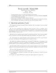
1. <strong>eZ430</strong>-<strong>RF2500</strong> Overview. Wireless Made Easy.The <strong>eZ430</strong>-<strong>RF2500</strong> is a complete USB-based MSP430 wirelessdevelopment tool providing all the hardware and software to evaluatethe MSP430F2274 microcontroller and CC2500 2.4-GHz wirelesstransceiver.The <strong>eZ430</strong>-<strong>RF2500</strong> uses the IAR Embedded Workbench Integrated<strong>Development</strong> Environment (IDE) or Code Composer Essentials (CCE) towrite, download, and debug an application. The debugger is unobtrusive,allowing the user to run an application at full speed with both hardwarebreakpoints and single stepping available while consuming no extrahardware resources.The <strong>eZ430</strong>-<strong>RF2500</strong>T target board is an out-of-the box wireless systemthat may be used with the USB debugging interface, as a stand-alonesystem with or without external sensors, or may be incorporated into anexisting design.The new USB debugging interface enables the <strong>eZ430</strong>-<strong>RF2500</strong> toremotely send and receive data from a PC using the MSP430Application UART.<strong>eZ430</strong>-<strong>RF2500</strong> features:• USB debugging and programming interface featuring a driverlessinstallation and application backchannel• 21 available development pins• Highly integrated, ultra-low-power MSP430 MCU with 16-MHzperformance• Two general-purpose digital I/O pins connected to green and redLEDs for visual feedback• Interruptible push button for user feedbackSpy Bi-Wire &MSP430 Appliation UARTPushbutton2x LEDsCC2500Chip AntennaUSB PoweredMSP430F2274Figure 1. <strong>eZ430</strong>-<strong>RF2500</strong>18 Accessible Pins2
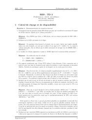
Figure 2. <strong>eZ430</strong>-<strong>RF2500</strong> Battery Board2. Kit Contents, <strong>eZ430</strong>-<strong>RF2500</strong>• The hardware includes:• Two <strong>eZ430</strong>-<strong>RF2500</strong>T target boards• One <strong>eZ430</strong>-RF USB debugging interface• One AAA battery pack with expansion board (batteries included)• One MSP430 <strong>Development</strong> <strong>Tool</strong> CD-ROM containingdocumentation and new development software for <strong>eZ430</strong>-<strong>RF2500</strong>:• MSP430x2xx Family User’s <strong>Guide</strong>, SLAU144• <strong>eZ430</strong>-<strong>RF2500</strong> User’s <strong>Guide</strong>, SLAU227• Code Composer Essentials (CCE), SLAC063• IAR Embedded Workbench (KickStart Version), SLAC050• <strong>eZ430</strong>-<strong>RF2500</strong> Sensor Monitor (Code and Visualizer), SLAC139NOTE: Please visit Texas Instrument’s website for latest versionswww.ti.com/msp4303
3. Developing With <strong>eZ430</strong>-<strong>RF2500</strong>T Target BoardThe <strong>eZ430</strong>-<strong>RF2500</strong> can be used as a stand-alone development tool.Additionally, the <strong>eZ430</strong>-<strong>RF2500</strong>T target board may also be detachedfrom the debugging interface and integrated into another design byremoving the plastic enclosure. The target board features anMSP430F2274 and most of its pins are easily accessible. The pins areshown in Figure 3 and the following tables:Figure 3. <strong>eZ430</strong>-<strong>RF2500</strong> <strong>Development</strong> <strong>Tool</strong><strong>eZ430</strong>-<strong>RF2500</strong>T Target Board PinoutsPin Function Description1 GND Ground reference2 VCC Supply voltage3 P2.0 / ACLK / A0 / OA0I0 General-purpose digital I/O pin / ACLK output / ADC10, analog input A04P2.1 / TAINCLK / SMCLK / A1 /OA0O5 P2.2 / TA 0 / A2 / OA0I167P2.3 / TA 1 / A3 / VREF − /VeREF − / OA1I1 / OA1OP2.4 / TA 2 / A4 / VREF + /VeREF + / OA1I08 P4.3 / TB0 / A12 / OA0O9 P4.4 / TB1 / A13 / OA1O10 P4.5 / TB2 / A14 / OA0I311 P4.6 / TBOUTH / A15 / OA1I3General-purpose digital I/O pin / ADC10, analog input A1Timer_A, clock signal at INCLK, SMCLK signal outputGeneral-purpose digital I/O pin / ADC10, analog input A2Timer_A, capture: CCI0B input/BSL receive, compare: OUT0 outputGeneral-purpose digital I/O pin / Timer_A, capture: CCI1B input, compare:OUT1 output / ADC10, analog input A3 / negative reference voltageoutput/inputGeneral-purpose digital I/O pin / Timer_A, compare: OUT2 output /ADC10, analog input A4 / positive reference voltage output/inputGeneral-purpose digital I/O pin / ADC10 analog input A12 /Timer_B, capture: CCI0B input, compare: OUT0 outputGeneral-purpose digital I/O pin / ADC10 analog input A13 /Timer_B, capture: CCI1B input, compare: OUT1 outputGeneral-purpose digital I/O pin / ADC10 analog input A14 /Timer_B, compare: OUT2 outputGeneral-purpose digital I/O pin / ADC10 analog input A15 /Timer_B, switch all TB0 to TB3 outputs to high impedance12 GND Ground reference13 P2.6 / XIN (GDO0) General-purpose digital I/O pin / Input terminal of crystal oscillator14 P2.7 / XOUT (GDO2) General-purpose digital I/O pin / Output terminal of crystal oscillator15 P3.2 / UCB 0SOMI / UCB 0SCLGeneral-purpose digital I/O pinUSCI_B0 slave out/master in in SPI mode, SCL I2C clock in I2C mode16 P3.3 / UCB 0CLK / UCA 0STEGeneral-purpose digital I/O pinUSCI_B0 clock input/output / USCI_A0 slave transmit enable17P3.0 / UCB 0STE / UCA 0CLK /A518 P3.1 / UCB 0SIMO / UCB 0SDAGeneral-purpose digital I/O pin / USCI_B0 slave transmit enable / USCI_A0clock input/output / ADC10, analog input A5General-purpose digital I/O pin / USCI_B0 slave in/master out in SPI mode,SDA I2C data in I2C mode*Pins 13 to 18 may be used to test the connection between the MSP430F2274 and CC2500.Battery Board PinoutsPin Function Description1 P3.4 / UCA 0TXD / UCA 0SIMOGeneral-purpose digital I/O pin / USCI_A0 transmit data output in UART mode(UART communication from 2274 to PC), slave in/master out in SPI mode2 GND Ground Reference3 #RST/SBWTDIOReset or nonmaskable interrupt input.Spy-Bi-Wire test data input/output during programming and test4 TEST/SBWTCKSelects test mode for JTAG pins on Port1. The device protection fuse isconnected to TEST. Spy-Bi-Wire test clock input during programming and test5 VCC (3.6V) Supply Voltage6 P3.5 / UCA 0RXD / UCA 0SOMIGeneral-purpose digital I/O pin / USCI_A0 receive data input in UART mode(UART communication from 2274 to PC), slave out/master in in SPI mode4
4. SpecificationsMSP430F2274• 16-MIPS performance• 200-ksps 10-bit SAR ADC• Two built-in operational amplifiers• Watchdog timer, 16-bit Timer_A3 and Timer_B3• USCI module supporting UART/LIN, (2) SPI, I2C, or IrDA• Five low-power modes drawing as little as 700 nA in standby•PARAMETER MIN TYP MAX UNITOPERATING CONDITIONSOperating supply voltage 1.8 3.6 VOperating free-air temperature range -40 85 ˚CCURRENT CONSUMPTIONActive mode at 1 MHz, 2.2 V 270 390 µAStandby mode 0.7 1.4 µAOff mode with RAM retention 0.1 0.5 µAOPERATING FREQUENCYVCC ≥ 3.3 V 16 MHzCC2500• 2.4-GHz radio-frequency (RF) transceiver• Programmable data rate up to 500 kbps• Low current consumption•PARAMETER MIN TYP MAX UNIT CONDITIONOPERATING CONDITIONSOperating supply voltage 1.8 3.6 VCURRENT CONSUMPTIONRX input signal at the sensitivity limit,250 kbps16.6 mA Optimized current18.8 mA Optimized sensitivityRX input signal 30 dB above thesensitivity limit, 250 kbps13.3 mA Optimized current15.7 mA Optimized sensitivityCurrent consumption TX (0 dBm) 21.2 mACurrent consumption TX (-12 dBm) 11.1 mARF CHARACTERISTICSFrequency range 2400 2483.5 MHzData rate (programmable) 1.2 500 kbpsOutput power (programmable) -30 0 dBmSensitivity, 10 kbps -99 dBmOptimized current, 2-FSK, 230-kHzRX filter bandwidth, 1% PER-101 dBm Optimized sensitivitySensitivity, 250 kbps -87 dBmOptimized current, 500-kHz RX filterbandwidth, 1% PER-89 dBm Optimized sensitivity5
5. Supported DevicesThe <strong>eZ430</strong>-RF USB debugging interface may be used as a standardFlash Emulation <strong>Tool</strong> through its Spy-Bi-Wire interface. The <strong>eZ430</strong>-RFUSB debugging interface supports the following MSP430 families:• MSP430F20xx• MSP430F22xxThe connector on the USB debugging interface is backward compatiblewith the <strong>eZ430</strong>-F2013 and T2012 target boards.RX3.6VTEST/SBWTCK#RST/SBWTDIOGNDTXSupports <strong>eZ430</strong>-F2013and T2012 target boards.Figure 4. <strong>eZ430</strong>-<strong>RF2500</strong> USB Debugging Interface 6-Pin Male Header6. MSP430 Application UARTThe <strong>eZ430</strong>-RF USB debugging interface features a back channelMSP430 Application UART that may be used independently of a debugsession. This allows the user to transfer serial data to a terminal windowat a fixed rate of 9600 bps with no flow control. See Figure 5 for typicalsettings.Figure 5. 9600 bps With No Flow ControlCheck the Device Manager for COM port assignment of the MSP430Application UART. For more details, see Section 14: Detailed HardwareInstallation <strong>Guide</strong>.6
7. Software Installation7.1. Installing the IDEThe CD-ROM includes two different development software tools for theMSP430—IAR Embedded Workbench KickStart and Code ComposerEssentials (CCE). The term “KickStart” refers to the limited version ofEmbedded Workbench that allows up to 4 KB of C-code compilation.The included CCE is also limited, but it allows up to 8 KB of codecompilation. The full version of CCE Pro offers unlimited codecompilation and can be purchased from www.ti.com/msp430.1. Insert the <strong>eZ430</strong>-<strong>RF2500</strong> CD-ROM into the computer. The<strong>eZ430</strong>-<strong>RF2500</strong> start page should automatically display. If it does notdisplay, use a browser to open “index.htm”, which is located in theroot directory of the <strong>eZ430</strong>-<strong>RF2500</strong> CD-ROM.The <strong>eZ430</strong>-<strong>RF2500</strong> is compatible with Windows® 2000 andWindows XP.2. Select Software IAR Workbench KickStart / Code ComposerEssentials and follow the instructions.3. Respond to the prompts to install the software. The installationprocedure installs the IDE and TI files. Finish the installation.7.2. Installing the Sensor Monitor Visualizer Application8. Hardware Installation1. Select Software Sensor Monitor Visualizer and follow theinstructions.2. Choose the installation path for the software.3. Open the <strong>eZ430</strong>-<strong>RF2500</strong> Sensor Monitor using the shortcut installedon the desktop.1. Insert the <strong>eZ430</strong>-RF into USB port. The debugging interfaceautomatically installs itself.2. When prompted for the software for the MSP430 Application UART,allow Windows to Install the software automatically. This is onlypossible if either IAR KickStart R4.64 (or higher) or the SensorMonitor Visualizer has already been installed.For more information, see Section 14: Detailed Hardware Installation<strong>Guide</strong>.7
9. SimpliciTI Network ProtocolThe SimpliciTI network protocol is a proprietary, low-power radiofrequency(RF) protocol targeting simple, small RF networks (
displays the temperature of both the End Devices and Access Point.Additionally, the PC application is capable of simulating distance fromits access point when the End Devices are moved. The number of EndDevices can be expanded by adding more target boards in the starnetwork as seen in Figure 6.10.1. Demo Hardware Setup10.2. Demo Firmware DownloadFigure 6. <strong>eZ430</strong>-<strong>RF2500</strong> Sensor Monitor1. Connect the <strong>eZ430</strong>-<strong>RF2500</strong> to a USB port on the PC.2. Connect the second <strong>eZ430</strong>-<strong>RF2500</strong>T target board to the batteryboard. Insert the jumper on the board to power up the device.The following steps describe how to update the demo applicationfirmware on the <strong>eZ430</strong>-<strong>RF2500</strong> target boards and are not required out ofthe box.1. Open IAR Workbench KickStart.2. Select Open Existing Workspace and browse for the demoapplication workspace (*.eww) file. The project is available on theCD or at http://www.ti.com/lit/zip/slac139.3. To download demo firmware, follow steps 3a for Access Pointfirmware and 3b for End Device firmware.3a. Right click on Access Point project in the workspace and click Setas Active as shown in Figure 7.3b. Right click on End Device project in the workspace and click Set asActive.9
10.3. Demo Software GUI Setup10.4. Demo OptionsFigure 7. IAR Embedded Workbench KickStart Workspace4. Select Project Debug in IAR to download the code for the targetboards.5. Select Debug Go to start running code while in debug mode.6. Select Debug Stop Debugging exits the debug mode whileleaving the target board executing code.1. Ensure the Access Point is connected to the PC.2. Apply power to the End Device.3. Launch <strong>eZ430</strong>-<strong>RF2500</strong> Sensor Monitor Demo Visualizer. Afterinstallation, a shortcut is placed on the desktop. It is available on theCD and online at http://www.ti.com/lit/zip/slac139.4. The application should automatically display End Devices when inrange.1. Go to Menu Settings.2. Under the settings menu, the demo application is capable ofdisplaying values in Celsius or Fahrenheit.3. Checking the box Disable Animations disables the dynamicdistance change, thus decreasing CPU processing on PC.4. See the demo application help file by clicking Help for more detailedoptions.10
11. Suggested ReadingThe primary sources of MSP430 information are the device-specific datasheets and user’s guides. The most up-to-date versions of the user’sguide documents available at the time of production have been providedon the CD-ROM included with this tool. The most current information isfound at www.ti.com/msp430. Information specific to the <strong>eZ430</strong>-<strong>RF2500</strong>development tool can be found at www.ti.com/ez430-rf.MSP430 device user’s guides and the FET user's guide may beaccessed from the main page on the CD-ROM under the User’s <strong>Guide</strong>ssection. The FET user's guide includes detailed information on settingup a project for the MSP430 using IAR.Documents describing the IAR tools (Workbench/C-SPY, the assembler,the C compiler, the linker, and the library) are located in common\docand 430\doc. The documents are in PDF format. Supplements to thedocuments (i.e., the latest information) are available in HTML formatwithin the same directories. 430\doc\readme_start.htm provides aconvenient starting point for navigating the IAR documentation.11
12. Frequently Asked Questions (FAQ)1) Does the <strong>eZ430</strong>-<strong>RF2500</strong> support fuse blow?The <strong>eZ430</strong>-RF USB debugging interface lacks the JTAG securityfuse-blow capability. To ensure firmware security on devices goingto production, the USB Flash Emulation <strong>Tool</strong> or the GangProgrammer, which include the fuse-blow feature, arerecommended.2) What is the voltage supplied to the <strong>eZ430</strong>-<strong>RF2500</strong>T target boardfrom the debugging interface?The <strong>eZ430</strong>-RF USB debugging interface supplies a regulated 3.6 Vto the <strong>eZ430</strong>-<strong>RF2500</strong>T target board.3) Can other programming tools interface to the <strong>eZ430</strong>-<strong>RF2500</strong>Ttarget board?The <strong>eZ430</strong>-<strong>RF2500</strong>T target board works with any programming toolsupporting the 2-wire Spy-Bi-Wire interface. Both the MSP430 USBFET (MSP-FET430UIF) and the Gang Programmer (MSP-GANG430) support these devices. See MSP-FET430 FlashEmulation <strong>Tool</strong> User’s <strong>Guide</strong> (SLAU138) for details on usingMSP430 USB FET and the Gang Programmer for a 2-wire Spy-Bi-Wire interface.4) What versions of IAR Embedded Workbench and CodeComposer Essentials are supported?The <strong>eZ430</strong>-<strong>RF2500</strong> hardware is supported by IAR EmbeddedWorkbench KickStart Release 4.64 (IAR 3.42F) and CodeComposer Essentials v2.03 (SP3) or higher.At the time of print, CCE is currently not supported by the SimpliciTIprotocol or the Sensor Monitor Demo. Please check the TI web sitefor updates.5) What are the part numbers for the connectors between the<strong>eZ430</strong>-RF USB debugger and the <strong>eZ430</strong>-<strong>RF2500</strong>T target board?• Header: Mill-Max 850-10-006-20-001000• Socket: Mill-Max 851-93-006-20-001000Mill-Max: http://www.mill-max.com6) Where can I obtain more information about the 2.4-GHz chipantenna?Part Number: 7488910245Wϋrth Electronik Group: www.we-online.com12
7) I am not able to select the MSP430 Application UART, cannotreceive data, or the demo app doesn’t appear to change.Ensure that the Application UART driver is correctly installed. This isdone by either running the installer for the Sensor Monitor Visualizeror IAR KickStart 3.42F or higher and following the directions inSection 14.To determine if the driver is correctly installed:1. Plug in the <strong>eZ430</strong>-RF USB debugging interface2. Right click My Computer and select Properties.3. Select the Hardware tab and click on Device Manager.4. Under Ports (COM & LPT) should be an entry for “MSP430Application UART (COM xx)”.If the entry is there, but no characters are received, restart the PC.If the Application UART is not listed, please install the driver byfollowing the instructions in Section 14: Detailed HardwareInstallation <strong>Guide</strong>.8) When trying to compiler the Sensor Monitor Demo project inIAR, I receive the following error:Error[e117]: Incompatible runtime models. Module ISR specifiesthat '__rt_version' must be '3', but module LHAL_GDOxHandlershas the value '2'Please use the latest version of the demo source code off the web(http://www.ti.com/lit/zip/slac139) and use IAR KickStart 4.x.Early versions of the demo code included a precompiled version ofthe SimpliciTI library for IAR 3.x. IAR 4.x changes the callingconventions, which returns Error[e117] when trying to build librariesfor an older version of the compiler.13
13. <strong>eZ430</strong>-<strong>RF2500</strong> SchematicsFigure 8. <strong>eZ430</strong>-RF, USB Debugging Interface, Schematic14
Figure 9. <strong>eZ430</strong>-RF, USB Debugging Interface, Schematic15
Figure 10. <strong>eZ430</strong>-<strong>RF2500</strong>T, Target Board and Battery Board, Schematic16
Figure 11. <strong>eZ430</strong>-RF, USB Debugger, PCB Components LayoutTop LayerBottom LayerFigure 12. <strong>eZ430</strong>-RF, USB Debugger, PCB LayoutFigure 13. <strong>eZ430</strong>-<strong>RF2500</strong>T, Target Board, PCB Layout17
6. The Found New Hardware Wizard opens a dialog window. Select No, not thistime and click Next (see Figure 16).Figure 16. Windows XP Found New Hardware Wizard7. Select Install the software automatically (Recommended) (see Figure 17), ifIAR KickStart R4.64 or higher has already been installed.Figure 17. Windows XP Hardware Wizard19
8. The Wizard should find the appropriate driver for a Windows XP system; it showsa warning that Microsoft did not certify the driver. The drivers have been testedexhaustively, and this warning may be ignored. Click Continue Anyway (seeFigure 18).Figure 18. Windows XP Warning9. The Wizard continues to install the driver and then provides notification when ithas finished the installation of the software.20
EVALUATION BOARD/KIT IMPORTANT NOTICETexas Instruments (TI) provides the enclosed product(s) under the following conditions:This evaluation board/kit is intended for use for ENGINEERING DEVELOPMENT, DEMONSTRATION, OR EVALUATIONPURPOSES ONLY and is not considered by TI to be a finished end-product fit for general consumer use. Persons handling theproduct(s) must have electronics training and observe good engineering practice standards. As such, the goods being providedare not intended to be complete in terms of required design-, marketing-, and/or manufacturing-related protectiveconsiderations, including product safety and environmental measures typically found in end products that incorporate suchsemiconductor components or circuit boards. This evaluation board/kit does not fall within the scope of the European Uniondirectives regarding electromagnetic compatibility, restricted substances (RoHS), recycling (WEEE), FCC, CE or UL, andtherefore may not meet the technical requirements of these directives or other related directives.Should this evaluation board/kit not meet the specifications indicated in the User’s <strong>Guide</strong>, the board/kit may be returned within30 days from the date of delivery for a full refund. THE FOREGOING WARRANTY IS THE EXCLUSIVE WARRANTY MADE BYSELLER TO BUYER AND IS IN LIEU OF ALL OTHER WARRANTIES, EXPRESSED, IMPLIED, OR STATUTORY, INCLUDINGANY WARRANTY OF MERCHANTABILITY OR FITNESS FOR ANY PARTICULAR PURPOSE.The user assumes all responsibility and liability for proper and safe handling of the goods. Further, the user indemnifies TI fromall claims arising from the handling or use of the goods. Due to the open construction of the product, it is the user’sresponsibility to take any and all appropriate precautions with regard to electrostatic discharge.EXCEPT TO THE EXTENT OF THE INDEMNITY SET FORTH ABOVE, NEITHER PARTY SHALL BE LIABLE TO THE OTHERFOR ANY INDIRECT, SPECIAL, INCIDENTAL, OR CONSEQUENTIAL DAMAGES.TI currently deals with a variety of customers for products, and therefore our arrangement with the user is not exclusive.TI assumes no liability for applications assistance, customer product design, software performance, or infringement ofpatents or services described herein.Please read the User’s <strong>Guide</strong> and, specifically, the Warnings and Restrictions notice in the User’s <strong>Guide</strong> prior to handling theproduct. This notice contains important safety information about temperatures and voltages. For additional information on TI’senvironmental and/or safety programs, please contact the TI application engineer or visit www.ti.com/esh.No license is granted under any patent right or other intellectual property right of TI covering or relating to any machine, process,or combination in which such TI products or services might be or are used.FCC WARNINGThis evaluation board/kit is intended for use for ENGINEERING DEVELOPMENT, DEMONSTRATION, OR EVALUATIONPURPOSES ONLY and is not considered by TI to be a finished end-product fit for general consumer use. It generates, uses,and can radiate radio frequency energy and has not been tested for compliance with the limits of computing devices pursuant topart 15 of FCC rules, which are designed to provide reasonable protection against radio frequency interference. Operation ofthis equipment in other environments may cause interference with radio communications, in which case the user at his ownexpense will be required to take whatever measures may be required to correct this interference.EVM WARNINGS AND RESTRICTIONSIt is important to operate this EVM within the input voltage range of 1.8 V to 3.6 V and the output voltage range of 1.8 V to 3.6 V.Exceeding the specified input range may cause unexpected operation and/or irreversible damage to the EVM. If there arequestions concerning the input range, please contact a TI field representative prior to connecting the input power.Applying loads outside of the specified output range may result in unintended operation and/or possible permanent damage tothe EVM. Please consult the EVM <strong>User's</strong> <strong>Guide</strong> prior to connecting any load to the EVM output. If there is uncertainty as to theload specification, please contact a TI field representative.During normal operation, some circuit components may have case temperatures greater than 60 C. The EVM is designed tooperate properly with certain components above 60 C as long as the input and output ranges are maintained. Thesecomponents include but are not limited to linear regulators, switching transistors, pass transistors, and current sense resistors.These types of devices can be identified using the EVM schematic located in the EVM <strong>User's</strong> <strong>Guide</strong>. When placingmeasurement probes near these devices during operation, please be aware that these devices may be very warm to the touch.Mailing Address: Texas Instruments, Post Office Box 655303, Dallas, Texas 75265Copyright © 2007, Texas Instruments Incorporated22


![td-res-4 [Compatibility Mode]](https://img.yumpu.com/45826987/1/184x260/td-res-4-compatibility-mode.jpg?quality=85)