10. 01 SEK SEK â Insulation Displacement Connector ... - Harting
10. 01 SEK SEK â Insulation Displacement Connector ... - Harting
10. 01 SEK SEK â Insulation Displacement Connector ... - Harting

Create successful ePaper yourself
Turn your PDF publications into a flip-book with our unique Google optimized e-Paper software.
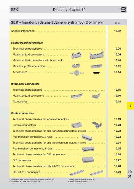
<strong>SEK</strong>Directory chapter 10<strong>SEK</strong> – <strong>Insulation</strong> <strong>Displacement</strong> <strong>Connector</strong> system (IDC), 2.54 mm pitchPageGeneral information . . . . . . . . . . . . . . . . . . . . . . . . . . . . . . . . . . . . . . . . . . . . . . <strong>10.</strong>02Solder board connectorsTechnical characteristics . . . . . . . . . . . . . . . . . . . . . . . . . . . . . . . . . . . . . . . . . <strong>10.</strong>04Male standard connectors . . . . . . . . . . . . . . . <strong>10.</strong>06Male standard connectors with board lock . . . . . . . . . . . . . . . . . . . . . . . . . . . <strong>10.</strong>10Male low profile connectors . . . . . . . . . . . . . . <strong>10.</strong>12Accessories . . . . . . . . . . . . . . . . . . . . . . . . . . <strong>10.</strong>14Wrap post connectorsTechnical characteristics . . . . . . . . . . . . . . . . . . . . . . . . . . . . . . . . . . . . . . . . . <strong>10.</strong>15Male standard connectors . . . . . . . . . . . . . . . <strong>10.</strong>16Accessories . . . . . . . . . . . . . . . . . . . . . . . . . . . . . . . . . . . . . . . . . . . . . . . . . . <strong>10.</strong>18<strong>SEK</strong>Cable connectorsTechnical characteristics for female connectors . . . . . . . . . . . . . . . . . . . . . . . <strong>10.</strong>19Female connectors . . . . . . . . . . . . . . . . . . . . . <strong>10.</strong>20Technical characteristics for pcb transition connectors, 2 rows . . . . . . . . . . . <strong>10.</strong>22Pcb transition connectors, 2 rows . . . . . . . . . . . . . . . . <strong>10.</strong>23Technical characteristics for pcb transition connectors, 4 rows . . . . . . . . . . . <strong>10.</strong>24Pcb transition connectors, 4 rows . . . . . . . . . . . . . . . . <strong>10.</strong>25Technical characteristics for DIP connectors . . . . . . . . . . . . . . . . . . . . . . . . . <strong>10.</strong>26DIP connectors . . . . . . . . . . . . . . . . . . . . . . . . . . . . . . <strong>10.</strong>27Technical characteristics for DIN 41 612 connectors . . . . . . . . . . . . . . . . . . . <strong>10.</strong>28DIN 41 612 connectors . . . . . . . . . . . . . . . . . . <strong>10.</strong>29<strong>Connector</strong>s with press-in termination see chapter 20<strong>Connector</strong>s for SMC see chapter 21Tooling see chapters 30 and 32Cables see chapter 4<strong>01</strong>0 .<strong>01</strong>
<strong>SEK</strong>General informationDeclaration of conformity<strong>SEK</strong>DeutscherAkkreditierungsRat10 .02
<strong>SEK</strong>General informationThe HARTING <strong>Insulation</strong> <strong>Displacement</strong> <strong>Connector</strong> systemEconomic and reliable connectionsThe flat cable and connector can be preassembledand used as a componentwith predetermined functionalcharacteristics.The HARTING insulation displacementcontacts pierce the insulation on the flatcable to provide a durable gastight connectionwith the wire.The HARTING 1) insulation displacementtechnique constitutes the ideal solutionto your wiring problems.1) The HARTING insulation displacementsystem meets all the characteristics,specifications and test conditions ofIEC 60 352-4.For “non standard applications” we canmanufacture designs to match yourrequirements.Please discuss requirements with us.HARTING <strong>SEK</strong> connectors incorporatethe latest design features and providethe assurance of high quality andreliability with economy.6-64 64 649-37 6-64<strong>SEK</strong>14-40 10-50Cable assemblies● HARTING can supply cable assembliesto customer specifications.● A wide range of connector typesavailable with various contact arrangementsconstitute the ideal solution toyour wiring problems.● Cables of all types in economic reellengths are available.Quality● Cables professionally assembled onHARTING work stations ensure reliableconnections.● Finished harnesses are subject to100% quality checks on a HARTINGtest device.● <strong>Insulation</strong> test.● Contact resistance test.Economy● The tested assembly of connectors andflat cables from one manufacturerguarantees a high degree of economyand reliability.● Investment for work stations and testdevices are not required.● Stocks of piece parts are reduced.10 .03
<strong>SEK</strong> IEC 60 603-13Number of contacts6--64Male header with angled solder pinsNo. ofPart No.Identification contacts Without levers With short levers With long leversMale header withangled solder pinsLength: 2.9 mm6 09 18 506 923 09 18 506 913 09 18 506 90310 09 18 510 923 09 18 510 913 09 18 510 90314 09 18 514 923 09 18 514 913 09 18 514 90316 09 18 516 923 09 18 516 913 09 18 516 90320 09 18 520 923 09 18 520 913 09 18 520 90326 09 18 526 923 09 18 526 913 09 18 526 90334 09 18 534 923 09 18 534 913 09 18 534 90340 09 18 540 923 09 18 540 913 09 18 540 90350 09 18 550 923 09 18 550 913 09 18 550 90360 09 18 560 923 09 18 560 913 09 18 560 90364 09 18 564 923 09 18 564 913 09 18 564 903<strong>SEK</strong>30 contacts and kinked version on requestMale header withangled solder pinsLength: 4.5 mm6 09 18 506 921* 09 18 506 911* 09 18 506 9<strong>01</strong>*10 09 18 510 921* 09 18 510 911* 09 18 510 9<strong>01</strong>*14 09 18 514 921* 09 18 514 911* 09 18 514 9<strong>01</strong>*16 09 18 516 921* 09 18 516 911* 09 18 516 9<strong>01</strong>*20 09 18 520 921* 09 18 520 911* 09 18 520 9<strong>01</strong>*26 09 18 526 921* 09 18 526 911* 09 18 526 9<strong>01</strong>*34 09 18 534 921* 09 18 534 911* 09 18 534 9<strong>01</strong>*40 09 18 540 921* 09 18 540 911* 09 18 540 9<strong>01</strong>*50 09 18 550 921* 09 18 550 911* 09 18 550 9<strong>01</strong>*60 09 18 560 921* 09 18 560 911* 09 18 560 9<strong>01</strong>*64 09 18 564 921* 09 18 564 911* 09 18 564 9<strong>01</strong>*10 .0630 contacts and kinked version on request* Not normally kept in stockFor accessories see page <strong>10.</strong>14For dimensions see page <strong>10.</strong>07For performance level 3 please specify digitFor performance level 2 please specify digit> 0.76 µm Au (30 µinch) on request7 * 7 76 6 65 * 5 * 5 *
<strong>SEK</strong> IEC 60 603-13Number of contacts6--64Male header with angled solder pinsIdentification Drawing Dimensions in mmMale headerNo. ofcontactsA B D E F G6 26.9 16.76 12.45 2.54 x 2 = 5.08 36.9 40.310 32.0 21.84 17.53 2.54 x 4 = <strong>10.</strong>16 42.0 45.414 37.1 26.92 22.61 2.54 x 6 = 15.24 47.1 50.416 39.6 29.46 25.15 2.54 x 7 = 17.78 49.6 53.020 44.7 34.54 30.23 2.54 x 9 = 22.86 54.7 58.126 52.3 42.16 37.85 2.54 x 12 = 30.48 62.3 65.734 62.5 52.32 48.<strong>01</strong> 2.54 x 16 = 40.64 72.5 75.840 70.1 59.94 55.63 2.54 x 19 = 48.26 80.1 83.550 82.8 72.64 68.33 2.54 x 24 = 60.96 92.8 96.260 95.5 85.34 81.03 2.54 x 29 = 73.66 105.5 108.964 100.6 90.42 86.11 2.54 x 31 = 78.74 1<strong>10.</strong>6 113.9Short leversfor use with femaleconnector withoutstrain relief clamp<strong>SEK</strong>No. 1 contactNo. 2 contacta) Solder pinsfor 0.9 mmdia. holeLong leversfor use with femaleconnector withstrain relief clampMarking No. 1 contactBoard drillingsNo. 1 contactNo. 2 contactFor accessories see page <strong>10.</strong>141)No polarization slotfor 6, 10 or 14 way male header2)No polarization slot for 6 way male header3)Pitch tolerance: ± 0.110 .07
<strong>SEK</strong> IEC 60 603-13Number of contacts6--64Male header with straight solder pinsNo. ofPart No.Identification contacts Without levers With short levers With long leversMale header withstraight solder pinsLength: 2.9 mm6 09 18 506 924 09 18 506 914 09 18 506 90410 09 18 510 924 09 18 510 914 09 18 510 90414 09 18 514 924 09 18 514 914 09 18 514 90416 09 18 516 924 09 18 516 914 09 18 516 90420 09 18 520 924 09 18 520 914 09 18 520 90426 09 18 526 924 09 18 526 914 09 18 526 90434 09 18 534 924 09 18 534 914 09 18 534 90440 09 18 540 924 09 18 540 914 09 18 540 90450 09 18 550 924 09 18 550 914 09 18 550 90460 09 18 560 924 09 18 560 914 09 18 560 90464 09 18 564 924 09 18 564 914 09 18 564 904<strong>SEK</strong>30 contacts and kinked version on requestMale header withstraight solder pinsLength: 4.5 mm6 09 18 506 922* 09 18 506 912* 09 18 506 902*10 09 18 510 922* 09 18 510 912* 09 18 510 902*14 09 18 514 922* 09 18 514 912* 09 18 514 902*16 09 18 516 922* 09 18 516 912* 09 18 516 902*20 09 18 520 922* 09 18 520 912* 09 18 520 902*26 09 18 526 922* 09 18 526 912* 09 18 526 902*34 09 18 534 922* 09 18 534 912* 09 18 534 902*40 09 18 540 922* 09 18 540 912* 09 18 540 902*50 09 18 550 922* 09 18 550 912* 09 18 550 902*60 09 18 560 922* 09 18 560 912* 09 18 560 902*64 09 18 564 922* 09 18 564 912* 09 18 564 902*10 .0830 contacts and kinked version on request* Not normally kept in stockFor accessories see page <strong>10.</strong>14For dimensions see page <strong>10.</strong>09For performance level 3 please specify digitFor performance level 2 please specify digit> 0.76 µm Au (30 µinch) on request7 * 7 76 6 65 * 5 * 5 *
<strong>SEK</strong> IEC 60 603-13Number of contacts6--64Male header with straight solder pinsIdentification Drawing Dimensions in mmMale headerNo. ofcontactsA C D E F G6 26.9 22.86 12.45 2.54 x 2 = 5.08 36.9 40.310 32.0 27.94 17.53 2.54 x 4 = <strong>10.</strong>16 42.0 45.414 37.1 33.02 22.61 2.54 x 6 = 15.24 47.1 50.416 39.6 35.56 25.15 2.54 x 7 = 17.78 49.6 53.020 44.7 40.64 30.23 2.54 x 9 = 22.86 54.7 58.126 52.3 48.26 37.85 2.54 x 12 = 30.48 62.3 65.734 62.5 58.42 48.<strong>01</strong> 2.54 x 16 = 40.64 72.5 75.840 70.1 66.04 55.63 2.54 x 19 = 48.26 80.1 83.550 82.8 78.74 68.33 2.54 x 24 = 60.96 92.8 96.260 95.5 91.44 81.03 2.54 x 29 = 73.66 105.5 108.964 100.6 96.52 86.11 2.54 x 31 = 78.74 1<strong>10.</strong>6 113.9Short leversfor use with femaleconnector withoutstrain relief clamp<strong>SEK</strong>No. 1 contactLong leversfor use with femaleconnector withstrain relief clampNo. 2 contacta) Solder pinsfor 0.9 mmdia. holeMarking No. 1 contactBoard drillingsNo. 1 contactNo. 2 contactFor accessories see page <strong>10.</strong>141)No polarization slotfor 6, 10 or 14 way male header2)No polarization slot for 6 way male header3)Pitch tolerance: ± 0.110 .09
<strong>SEK</strong> IEC 60 603-13Number of contacts6--64Male header with angled solder pins and board lockNo. ofPart No.Identification contacts Without levers With short levers With long leversMale header withangled solder pinsand pcb board lockLength: 2.9 mmfor 1.6 mm pcb thicknessTo hold the connector on the pcb before the solderingprocess, two board locks have been added on the maleheader with angled solder pins.6 09 18 506 973* 09 18 506 963* 09 18 506 953*10 09 18 510 973* 09 18 510 963* 09 18 510 953*14 09 18 514 973* 09 18 514 963* 09 18 514 953*16 09 18 516 973* 09 18 516 963* 09 18 516 953*20 09 18 520 973* 09 18 520 963* 09 18 520 953*26 09 18 526 973* 09 18 526 963* 09 18 526 953*34 09 18 534 973* 09 18 534 963* 09 18 534 953*40 09 18 540 973* 09 18 540 963* 09 18 540 953*50 09 18 550 973* 09 18 550 963* 09 18 550 953*60 09 18 560 973* 09 18 560 963* 09 18 560 953*64 09 18 564 973* 09 18 564 963* 09 18 564 953*<strong>SEK</strong>10 .10* Not normally kept in stock30 contacts on requestFor performance level 3 please specify digitFor performance level 2 please specify digit> 0.76 µm Au (30 µinch) on request7 7 76 6 65 5 5
<strong>SEK</strong> IEC 60 603-13Number of contacts6--64Male header with angled solder pins and board lockIdentification Drawing Dimensions in mmMale headerNo. ofcontactsA B D E F G6 26.9 16.76 12.45 2.54 x 2 = 5.08 36.9 40.310 32.0 21.84 17.53 2.54 x 4 = <strong>10.</strong>16 42.0 45.414 37.1 26.92 22.61 2.54 x 6 = 15.24 47.1 50.416 39.6 29.46 25.15 2.54 x 7 = 17.78 49.6 53.020 44.7 34.54 30.23 2.54 x 9 = 22.86 54.7 58.126 52.3 42.16 37.85 2.54 x 12 = 30.48 62.3 65.734 62.5 52.32 48.<strong>01</strong> 2.54 x 16 = 40.64 72.5 75.840 70.1 59.94 55.63 2.54 x 19 = 48.26 80.1 83.550 82.8 72.64 68.33 2.54 x 24 = 60.96 92.8 96.260 95.5 85.34 81.03 2.54 x 29 = 73.66 105.5 108.964 100.6 90.42 86.11 2.54 x 31 = 78.74 1<strong>10.</strong>6 113.9Short leversfor use with femaleconnector withoutstrain relief clamp<strong>SEK</strong>No. 2 contactNo. 1 contactLong leversfor use with femaleconnector withstrain relief clampMarking No. 1 contactBoard drillingsNo. 1 contactNo. 2 contactFor accessories see page <strong>10.</strong>141)No polarization slotfor 6, 10 or 14 way male header2)No polarization slot for 6 way male header3)Pitch tolerance: ± 0.110 .11
<strong>SEK</strong> IEC 60 603-13Number of contacts6--64Low-profile male header, angled solder pinsNo. ofIdentification contacts Part No. Drawing Dimensions in mmMale header withangled solder pinsLength: 2.9 mmNo. ofcontacts6 09 18 506 323 610 09 18 510 323 1<strong>01</strong>4 09 18 514 323 1416 09 18 516 323 1620 09 18 520 323 2026 09 18 526 323 2634 09 18 534 323 3440 09 18 540 323 4050 09 18 550 323 5060 09 18 560 323 6064 09 18 564 323 64A B E15.2 12.78 2.54 x 2 = 5.0820.3 17.86 2.54 x 4 = <strong>10.</strong>1625.4 22.94 2.54 x 6 = 15.2427.9 25.48 2.54 x 7 = 17.7833.0 30.56 2.54 x 9 = 22.8640.6 38.18 2.54 x 12 = 30.4850.8 48.34 2.54 x 16 = 40.6458.4 55.96 2.54 x 19 = 48.2671.3 68.66 2.54 x 24 = 60.9684.0 81.36 2.54 x 29 = 73.6689.1 86.44 2.54 x 31 = 78.74Solder pins for0.9 mm dia. holeMarking No. 1 contact<strong>SEK</strong>No. 2 contactFor performance level 3 please specify digitFor performance level 2 please specify digit> 0.76 µm Au (30 µinch) on request765 *No. 1 contactNo. 2 contactNo. 1 contact10 .12No. ofIdentification contacts Part No. Drawing Dimensions in mmLocking lever forfemale connectorwith strain reliefin conjunction with lowprofilemale headerWhen the security oflatching is required andspace is a premium,these locking levers canbe fitted onto the strainrelief of the HARTINGfemale connector.09 18 000 9905 4)* Not normally kept in stock1)No polarization slot for 6, 10 or 14 way male header2)No polarization slot for 6 way male headerStrain relief clampFemale connectorLow-profile male header3)Pitch tolerance: ± 0.14)Order 2 per female connector
<strong>SEK</strong> IEC 60 603-13Number of contacts6--64Low-profile male header, straight solder pinsNo. ofIdentification contacts Part No. Drawing Dimensions in mmMale header withstraight solder pinsLength: 2.9 mmNo. ofcontacts6 09 18 506 324 610 09 18 510 324 1<strong>01</strong>4 09 18 514 324 1416 09 18 516 324 1620 09 18 520 324 2026 09 18 526 324 2634 09 18 534 324 3440 09 18 540 324 4050 09 18 550 324 5060 09 18 560 324 6064 09 18 564 324 64A B E15.2 12.78 2.54 x 2 = 5.0820.3 17.86 2.54 x 4 = <strong>10.</strong>1625.4 22.94 2.54 x 6 = 15.2427.9 25.48 2.54 x 7 = 17.7833.0 30.56 2.54 x 9 = 22.8640.6 38.18 2.54 x 12 = 30.4850.8 48.34 2.54 x 16 = 40.6458.4 55.96 2.54 x 19 = 48.2671.3 68.66 2.54 x 24 = 60.9684.0 81.36 2.54 x 29 = 73.6689.1 86.44 2.54 x 31 = 78.74Solder pins for0.9 mm dia. holeMale header withstraight solder pinsLength: 4.5 mm6 09 18 506 322*10 09 18 510 322*14 09 18 514 322*16 09 18 516 322*20 09 18 520 322*26 09 18 526 322*34 09 18 534 322*40 09 18 540 322*50 09 18 550 322*60 09 18 560 322*64 09 18 564 322*Marking No. 1 contactNo. 2 contactNo. 1 contact<strong>SEK</strong>For performance level 3 please specify digitFor performance level 2 please specify digit> 0.76 µm Au (30 µinch) on request765 *No. 2 contactNo. 1 contactNo. ofIdentification contacts Part No. Drawing Dimensions in mmLocking lever forfemale connectorwith strain reliefin conjunction with lowprofilemale headerWhen the security oflatching is required andspace is a premium,these locking levers canbe fitted onto the strainrelief of the HARTINGfemale connector.09 18 000 9905 4)* Not normally kept in stock1)No polarization slot for 6, 10 or 14 way male header2)No polarization slot for 6 way male headerStrain relief clampFemale connectorLow-profile male header3)Pitch tolerance: ± 0.14)Order 2 per female connector10 .13
<strong>SEK</strong> IEC 60 603-13AccessoriesIdentification Part No. Drawing Dimensions in mmPolarization key09 18 500 9902 1)1) Part No. comprises2 keysLocking lever(snaps into place, canbe fitted wheneverrequired)Long:LongShort09 18 000 9903 2)Short:2) Order 2 permale header09 18 000 9904 2)For use with female connectorwith strain relief clampFor use with female connectorwithout strain relief clampFixing screwsfor 1.6 mm P.C. board<strong>SEK</strong>09 18 000 9906 3)3) Part No. comprises50 piecesCoding system withloss of contactCode pinTo avoid cross-plugging adjacent connectors a coding system is required.A code pin is inserted into the appropriate cavity in the female connector.The corresponding male contact is removed by a special removal tool.09 18 000 99<strong>01</strong> 4)Removal toolformale contacts09 99 000 <strong>01</strong>3310 .144) Part No. comprises6 code pins
<strong>SEK</strong> Wrap post connectorsTechnical characteristicsNumber of contacts 6, 10, 14, 16, 20, 26, 34, 40,50, 60, 64Contact arrangementstraight, angledContact length15 mmApprovals IEC 60 603-13DIN EN 60 603-13D 2632BT 224NFC 93-428 (HE 10)comply with MIL DTL 83 503Pitch 2.54 mm [0.100“]Working current1 AWorking voltage500 Vfor pollution degree 1<strong>SEK</strong>Test voltage U r.m.s.1 kVContact resistance<strong>Insulation</strong> resistance≤ 20 mΩ≥ 10 9 ΩTemperature range-55 O C … + 125 O CThe maximum temperatureincludes heating of contactsand ambient temperatureTerminations0.6 mm x 0.6 mmDiagonal: 0.86 mmMaterialsMouldingContact surfaceContact zoneThermoplastic resin (PBTP)UL 94-V0gold-plated according toperformance level 1)1)Performance level 3 as per IEC 60 603-13, ≥ 50 mating cycles, no gas testPerformance level 2 as per IEC 60 603-13, ≥ 250 mating cycles, 4 days gas testas per MIL DTL 83 503, > 0.76 µm Au (30 µ inch), other performance levels on request10 .15
<strong>SEK</strong> IEC 60 603-13Number of contacts6--64Male header with wrap postsNo. ofPart No.Identification contacts Without levers With short levers With long leversMale header withangled wrap postsLength: 15 mm0.6 mm6 09 18 506 926* 09 18 506 916* 09 18 506 906*10 09 18 510 926* 09 18 510 916* 09 18 510 906*14 09 18 514 926* 09 18 514 916* 09 18 514 906*16 09 18 516 926* 09 18 516 916* 09 18 516 906*20 09 18 520 926* 09 18 520 916* 09 18 520 906*26 09 18 526 926* 09 18 526 916* 09 18 526 906*34 09 18 534 926* 09 18 534 916* 09 18 534 906*40 09 18 540 926* 09 18 540 916* 09 18 540 906*50 09 18 550 926* 09 18 550 916* 09 18 550 906*60 09 18 560 926* 09 18 560 916* 09 18 560 906*64 09 18 564 926* 09 18 564 916* 09 18 564 906*<strong>SEK</strong>Male header withstraight wrap postsLength: 15 mm0.6 mm6 09 18 506 927* 09 18 506 917* 09 18 506 907*10 09 18 510 927* 09 18 510 917* 09 18 510 907*14 09 18 514 927* 09 18 514 917* 09 18 514 907*16 09 18 516 927* 09 18 516 917* 09 18 516 907*20 09 18 520 927* 09 18 520 917* 09 18 520 907*26 09 18 526 927* 09 18 526 917* 09 18 526 907*34 09 18 534 927* 09 18 534 917* 09 18 534 907*40 09 18 540 927* 09 18 540 917* 09 18 540 907*50 09 18 550 927* 09 18 550 917* 09 18 550 907*60 09 18 560 927* 09 18 560 917* 09 18 560 907*64 09 18 564 927* 09 18 564 917* 09 18 564 907*10 .16* Not normally kept in stockFor accessories see page <strong>10.</strong>18For dimensions see page <strong>10.</strong>17For performance level 3 please specify digitFor performance level 2 please specify digit> 0.76 µm Au (30 µinch) on request7 7 76 6 65 5 5
<strong>SEK</strong> IEC 60 603-13Number of contacts6--64Male header with wrap postsIdentification Drawing Dimensions in mmMale headerNo. ofcontactsA B C D E F G6 26.9 16.76 22.86 12.45 2.54 x 2 = 5.08 36.9 40.310 32.0 21.84 27.94 17.53 2.54 x 4 = <strong>10.</strong>16 42.0 45.414 37.1 26.92 33.02 22.61 2.54 x 6 = 15.24 47.1 50.416 39.6 29.46 35.56 25.15 2.54 x 7 = 17.78 49.6 53.020 44.7 34.54 40.64 30.23 2.54 x 9 = 22.86 54.7 58.126 52.3 42.16 48.26 37.85 2.54 x 12 = 30.48 62.3 65.734 62.5 52.32 58.42 48.<strong>01</strong> 2.54 x 16 = 40.64 72.5 75.840 70.1 59.94 66.04 55.63 2.54 x 19 = 48.26 80.1 83.550 82.8 72.64 78.74 68.33 2.54 x 24 = 60.96 92.8 96.260 95.5 85.34 91.44 81.03 2.54 x 29 = 73.66 105.5 108.964 100.6 90.42 96.52 86.11 2.54 x 31 = 78.74 1<strong>10.</strong>6 113.9Long leversfor use with female connectorwith strain relief clampShort leversfor use with female connectorwithout strain relief clamp<strong>SEK</strong>Angled versionsStraight versionsNo. 1 contactNo. 1 contactNo. 2 contacta) Wrap posts0.6 mmNo. 2 contacta) Wrap posts0.6 mmBoard drillingsMarking No. 1 contactNo. 1 contactMarking No. 1 contactNo. 1 contactFor accessories see page <strong>10.</strong>18No. 2 contact1)No polarization slotfor 6, 10 or 14 way male headerNo. 2 contact2)No polarization slot for 6 way male header3)Pitch tolerance: ± 0.110 .17
<strong>SEK</strong> IEC 60 603-13AccessoriesIdentification Part No. Drawing Dimensions in mmPolarization key09 18 500 9902 1)1) Part No. comprises2 keysLocking lever(snaps into place, canbe fitted wheneverrequired)Long:LongShort09 18 000 9903 2)Short:2) Order 2 permale header09 18 000 9904 2)For use with female connectorwith strain relief clampFor use with female connectorwithout strain relief clampFixing screwsfor 1.6 mm P.C. board<strong>SEK</strong>09 18 000 9906 3)3) Part No. comprises50 piecesCoding system withloss of contactCode pinTo avoid cross-plugging adjacent connectors a coding system is required.A code pin is inserted into the appropriate cavity in the female connector.The corresponding male contact is removed by a special removal tool.09 18 000 99<strong>01</strong> 4)Removal toolformale contacts09 99 000 <strong>01</strong>3310 .184) Part No. comprises6 code pins
<strong>SEK</strong> Cable connectors femaleTechnical characteristicsNumber of contacts 6, 10, 14, 16, 20, 26, 30*,34, 40, 50, 60, 64Approvals IEC 60 603-13DIN EN 60 603-13D 2632BT 224NFC 93-428 (HE 10)UL recognized: E102079comply with MIL DTL 83 503Pitch 2.54 mm [0.100“]Working current1 AWorking voltage320 Vfor pollution degree 1Test voltage U r.m.s.1 kV<strong>SEK</strong>Contact resistance<strong>Insulation</strong> resistance≤ 20 mΩ≥ 10 9 ΩTemperature range-55 O C … + 125 O CThe maximum temperatureincludes heating of contactsand ambient temperatureTerminationsIDC flat cable1.27 mm [0.050”] pitch:AWG 26/7 – AWG 28/7MaterialsMouldingContact surfaceContact zoneThermoplastic resin (PBTP)UL 94-V0gold-plated according toperformance level 1)1)Performance level 3 as per IEC 60 603-13, ≥ 50 mating cycles, no gas test * on requestPerformance level 2 as per IEC 60 603-13, ≥ 250 mating cycles, 4 days gas testas per MIL DTL 83 503, > 0.76 µm Au (30 µ inch), other performance levels on request10 .19
<strong>SEK</strong> IEC 60 603-13Number of contacts6--64Female connectorNo. ofIdentification contacts Part No. Drawing Dimensions in mmFemale connectorwith centralpolarizationwithoutstrain relief clampopen endcoverclosed endcover6 09 18 506 803 09 18 506 80410 09 18 510 803 09 18 510 80414 09 18 514 803 09 18 514 80416 09 18 516 803 09 18 516 80420 09 18 520 803 09 18 520 80426 09 18 526 803 09 18 526 80434 09 18 534 803 09 18 534 80440 09 18 540 803 09 18 540 80450 09 18 550 803 09 18 550 80460 09 18 560 803 09 18 560 80464 09 18 564 803 09 18 564 804No. 1 contactNo. 2 contactopen endcoveroptionclosed endcover<strong>SEK</strong>withstrain relief clamp30 contactson request6 09 18 506 813 09 18 506 814*10 09 18 510 813 09 18 510 814*14 09 18 514 813 09 18 514 814*16 09 18 516 813 09 18 516 814*20 09 18 520 813 09 18 520 814*26 09 18 526 813 09 18 526 814*34 09 18 534 813 09 18 534 814*40 09 18 540 813 09 18 540 814*50 09 18 550 813 09 18 550 814*60 09 18 560 813 09 18 560 814*64 09 18 564 813 09 18 564 814*MarkingNo. 1 contactStrain reliefclampoptionFemale connectorwithout centralpolarizationwithoutstrain relief clampopen endcover10 09 18 510 805*14 09 18 514 805*16 09 18 516 805*20 09 18 520 805*26 09 18 526 805*34 09 18 534 805*40 09 18 540 805*50 09 18 550 805*60 09 18 560 805*64 09 18 564 805*No. 1 contactNo. 2 contactMarkingNo. 1 contactStrain reliefclampoption10 .20withstrain relief clamp30 contactson requestFor performance level 3 please specify digitFor performance level 2 please specify digit> 0.76 µm Au (30 µinch) on request10 09 18 510 815*14 09 18 514 815*16 09 18 516 815*20 09 18 520 815*26 09 18 526 815*34 09 18 534 815*40 09 18 540 815*50 09 18 550 815*60 09 18 560 815*64 09 18 564 815*7 7 *6 65 * 5 *No. ofcontacts6 10 14 16 20 26 34 40 50 60 64A 12.20 17.30 22.40 24.90 30.00 37.60 47.80 55.40 68.10 80.80 85.90B 5.08 <strong>10.</strong>16 15.24 17.78 22.86 30.48 40.64 48.26 60.96 73.66 78.741)Pitch tolerance: ± 0.1 * Not normally kept in stock
<strong>SEK</strong> IEC 60 603-13Number of contacts6--64Strain relief clamp/Locking leverNo. ofIdentification contacts Part No. Drawing Dimensions in mmStrain reliefclamp30 contactson requestLocking lever forfemale connectorOnly in conjunctionwith low-profile maleheader andstrain reliefNo. ofcontacts6 09 18 506 9002 610 09 18 510 9002 1<strong>01</strong>4 09 18 514 9002 1416 09 18 516 9002 1620 09 18 520 9002 2026 09 18 526 9002 2634 09 18 534 9002 3440 09 18 540 9002 4050 09 18 550 9002 5060 09 18 560 9002 6064 09 18 564 9002 64A12.217.322.424.930.037.647.855.468.180.885.9Strain relief clamp<strong>SEK</strong>When the security oflatching is requiredand space is apremium, theselocking levers can befitted onto the strainrelief of the HARTINGfemale connector. Thiscan then be used inconjunction with malelow profile headers(see pages <strong>10.</strong>12 and<strong>10.</strong>13).Female connectorLow-profile male header09 18 000 9905 1) 10 .Coding system withloss of contactTo avoid cross-plugging adjacent connectors a coding system is required.A code pin is inserted into the appropriate cavity in the female connector.The corresponding male contact is removed by a special removal tool.Code pin09 18 000 99<strong>01</strong> 2)Removal tool formale contacts1) Order 2 per female connector2) Part No. comprises 6 code pins09 99 000 <strong>01</strong>3321
<strong>SEK</strong> Cable connectors pcb 2 rowsTechnical characteristicsNumber of contacts 6, 8, 10, 14, 16, 20, 24, 26, 30, 34,40, 50, 60, 64Pitch On pcb side: 2.54 mm [0.100“]On cable side: 1.27 mm [0.050“]Working current1 ATest voltage U r.m.s.1 kV AC – 1 minuteContact resistance<strong>Insulation</strong> resistance15 mΩ max. mated≥ 10 9 Ω<strong>SEK</strong>Temperature range-55 O C … + 105 O CThe maximum temperatureincludes heating of contactsand ambient temperatureTerminationsSolder pins:0.635 mm x 0.3 mmDimensions for pcb hole:Standard version: Ø 0.9 ±0.10 mmKinked version: Ø 1.0 ±0.05 mmDiagonal: 0.71 mmIDC flat cable1.27 mm [0.050“] pitch: AWG 28/7MaterialsMouldingThermoplastic resin (PBT)UL 94-V<strong>01</strong>0 .22
<strong>SEK</strong>Number of contacts6--64Pcb transition connector, 2 rowsNo. ofIdentification contacts Part No. Drawing Dimensions in mmPcb transitionconnector2 rowsStandard versionNo. ofcontacts6 09 18 106 9621 68 *09 18 108 9621* 810 09 18 110 9621 1<strong>01</strong>4 09 18 114 9621 1416 09 18 116 9621 1620 09 18 120 9621 2024 *09 18 124 9621* 2426 09 18 126 9621 2630 *09 18 130 9621* 3034 09 18 134 9621 3440 09 18 140 9621 4050 09 18 150 9621 5060 09 18 160 9621 6064 09 18 164 9621 64A ±0.38 B ±0.1<strong>01</strong>2.92 2.54 x 2 = 5.0815.46 2.54 x 3 = 7.6218.00 2.54 x 4 = <strong>10.</strong>1623.08 2.54 x 6 = 15.2425.62 2.54 x 7 = 17.7830.74 2.54 x 9 = 22.8635.78 2.54 x 11 = 27.9438.32 2.54 x 12 = 30.4843.40 2.54 x 14 = 35.5648.48 2.54 x 16 = 40.6456.10 2.54 x 19 = 48.2668.80 2.54 x 24 = 60.9681.50 2.54 x 29 = 73.6686.58 2.54 x 31 = 78.74Pcb transitionconnector2 rowsKinked version2 kinked pinsat each extremity6 *09 18 106 9421*8 *09 18 108 9421*10 *09 18 110 9421*14 *09 18 114 9421*16 *09 18 116 9421*20 *09 18 120 9421*24 *09 18 124 9421*26 *09 18 126 9421*30 *09 18 130 9421*34 *09 18 134 9421*40 *09 18 140 9421*50 *09 18 150 9421*60 *09 18 160 9421*64 *09 18 164 9421*Lead No. 1Lead No. 2Kinked pinspre-assembledpreassembledStandard versionassembledKinked versionassembled<strong>SEK</strong>Board drillingsLead No. 2Ø 0.90 ±0.10 standard versionØ 1.00 ±0.05 kinked version* Not normally kept in stock1)Pitch tolerance: ± 0.05Lead No. 110 .23
<strong>SEK</strong> Cable connectors pcb 4 rowsTechnical characteristicsNumber of contacts* 10, 16, 20, 26, 34, 40, 50Pitch On pcb side: 2.54 mm [0.100“]On cable side: 1.27 mm [0.050“]Working current1 ATest voltage U r.m.s.500 VContact resistance<strong>Insulation</strong> resistance≤ 20 mΩ≥ 10 12 Ω<strong>SEK</strong>Temperature range-40 O C … + 125 O CThe maximum temperature includesheating of contacts and ambienttemperatureTerminationsSolder pins0.45 mm x 0.35 mmfor pcb hole Ø 0.8 mmDiagonal: 0.58 mmIDC flat cable1.27 mm [0.050“] pitch:AWG 26/7 – AWG 28/7 – AWG 30/1MaterialsMouldingThermoplastic resin (PC)UL 94-V<strong>01</strong>0 .24* Others on request
<strong>SEK</strong>Number of contacts10--50Pcb transition connector, 4 rowsNo. ofIdentification contacts Part No. Drawing Dimensions in mmPcb transitionNo. ofconnectorcontactsAB4 rows 10 09 19 <strong>01</strong>0 9643* 10 17.78 1.27 x 9 = 11.4316 09 19 <strong>01</strong>6 9643* 16 25.40 1.27 x 15 = 19.0520 09 19 020 9643* 20 30.48 1.27 x 19 = 24.1326 09 19 026 9643* 26 38.10 1.27 x 25 = 31.7534 09 19 034 9643* 34 48.26 1.27 x 33 = 41.9140 09 19 040 9643* 40 55.88 1.27 x 39 = 49.5350 09 19 050 9643* 50 68.58 1.27 x 49 = 62.23Lead No. 1Lead No. 2<strong>SEK</strong>Board drillingsLead No. 2 Lead No. 1* Not normally kept in stock.1)Pitch tolerance: ± 0.110 .25
<strong>SEK</strong> Cable connectors DIPTechnical characteristicsNumber of contacts* 14, 16, 24, 28, 40Pitch On pcb side: 2.54 mm [0.100“]On cable side: 1.27 mm [0.050“]Working current1 ATest voltage U r.m.s.500 VContact resistance<strong>Insulation</strong> resistance≤ 20 mΩ≥ 10 12 Ω<strong>SEK</strong>Temperature range-40 O C … + 125 O CThe maximum temperatureincludes heating of contactsand ambient temperatureTerminationsSolder pins0.45 mm x 0.35 mmfor pcb hole Ø 0.8 mmDiagonal: 0.58 mmIDC flat cable1.27 mm [0.050“] pitch:AWG 26/7 – AWG 28/7MaterialsMouldingThermoplastic resin (PC)UL 94-V<strong>01</strong>0 .26* Others on request
<strong>SEK</strong>Number of contacts14--40DIP connector for IC base or for soldering into pcbNo. ofIdentification contacts Part No. Drawing Dimensions in mmDIP connectorNo. ofcontacts14 09 17 <strong>01</strong>4 9622* 1416 09 17 <strong>01</strong>6 9622* 1624 09 17 024 9622* 2428 09 17 028 9622* 2840 09 17 040 9622* 40A B C D20.5 2.54 x 6 = 15.24 11,0 7.6223.0 2.54 x 7 = 17.78 11,0 7.6233.0 2.54 x 11 = 27.94 18.7 15.2438.1 2.54 x 13 = 33.02 18.7 15.2453.3 2.54 x 19 = 48.26 18.7 15.24Lead No. 2Lead No. 1<strong>SEK</strong>Board drillings* Not normally kept in stock1)Pitch tolerance: ± 0.1Lead No. 1Lead No. 210 .27
DIN 41 612 Cable connectors types B and CTechnical characteristicsNumber of contacts 64Pitch 2.54 mm [0.100“]Working current1 A max.ClearanceCreepage≥ 1.2 mm≥ 1.2 mmWorking voltageThe working voltage alsodepends on the clearanceand creepage dimensionsof the pcb itself, and theassociated wiringTest voltage U r.m.s.according to the safetyregulations of the equipment1 kVContact resistance<strong>Insulation</strong> resistance≤ 20 mΩ≥ 10 12 Ω<strong>SEK</strong>Temperature range -55 °C … + 125 °CThe maximum temperatureincludes heating of contactsand ambient temperatureTerminationFemale connector<strong>Insulation</strong> displacement:AWG 28/7Insertion and withdrawalforce≤ 60 N10 .28MaterialsMouldingContactsContact surfaceContact zoneThermoplastic resin,glass-fibre filled, UL 94-V0Copper alloyselectively plated according toperformance level
DIN 41 612Number of contacts64Female connectors for insulation displacementNo. ofIdentification contacts Part No. Drawing Dimensions in mmFemale connectorfor insulationdisplacementperformance level 2Type B 6409 02 264 68281. contactperformance level 309 02 264 78281. contactLead number 1 of flat cable on contact 1 bContact arrangement View from termination side<strong>SEK</strong>Type C 64performance level 209 03 264 6828c) 09 03 764 6828 c)1. contactperformance level 309 03 264 78281. contactLead number 1 of flat cable on contact 1 cContact arrangement View from termination sideMateable with 3-row male connector Type C.No female contact in middle row.Panel cut outMale connectors see DIN 41 612 cataloguec) <strong>Connector</strong>s with codinga bType B 8.3 <strong>10.</strong>16Type C <strong>10.</strong>8 12.7<strong>01</strong>0 .29
Notes<strong>SEK</strong>10 .30