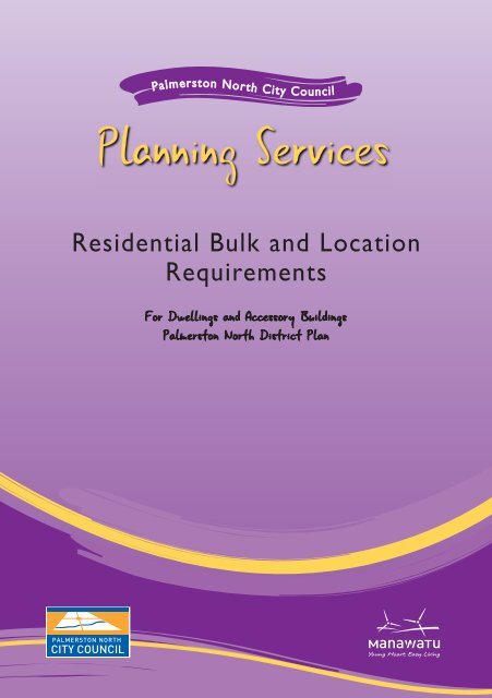
Residential Bulk and Location Requirements - Palmerston North ...
Residential Bulk and Location Requirements - Palmerston North ...
Residential Bulk and Location Requirements - Palmerston North ...

You also want an ePaper? Increase the reach of your titles
YUMPU automatically turns print PDFs into web optimized ePapers that Google loves.
Boundary Separation Distancei) Any dwelling on a front or corner site shall be located at least 3 metres from theboundary with any road, with the exception of that part of a dwelling containing agarage or carport which may be located not less than 1.5 metres from the boundarywith any road.ii) All other boundariesa) That part of the facade of a dwelling containing a window to a habitable roomshall be located at least 3 metres from any boundaryb) Any part of a dwelling not included in a) shall be located at least 1.5 metres fromany boundary.3
Site AreaMinimum Net Site Area of 350m 2 for each dwelling unit.Site CoverageThe maximum amount of site which may be covered by buildings:a) 40% on sites of less than 500m 2b) 200m 2 on sites of 500m 2 to 572m 2c) 35% on sites over 572m 2On-Site Carparking2 parks per dwelling unitAccessOne st<strong>and</strong>ard crossing of 3 metres shall be provided except where a dwelling has a doublegarage facing a front boundary <strong>and</strong> is set back less than 7 metres from the front boundaryin which case the crossing width can be up to 5 metres wide or the width of the doubledoors, which ever is lesser. Other access provisions may apply, please contact a CouncilOffi cer in the Planning Services Section, at the City Council, for further information.Certain areas are affected by specific restrictions such as the following:1. Air Noise Controls2. Minimum Floor Levels3. Ponding Areas4. River Terrace <strong>and</strong> Cliff Protection Lines5. Developable <strong>and</strong> Undevelopable L<strong>and</strong>6. Stopbanks7. Notable Trees/Objects/Sites of Cultural Heritage Value8. Savage Crescent Conservation AreaPlease discuss with Planning Services whether any of these restrictions affect your property.Note: 1. The following Design Guides are available:Aokautere Housing Design Guide <strong>and</strong> Savage Crescent Design Guidelines.2. For any relaxation of the provisions outlined in this brochure, please contact a Council Officer inthe Planning Services section at the <strong>Palmerston</strong> <strong>North</strong> City Council.4
Height of Buildings• No building shall exceed a maximum height of 9 metres.• Where a boundary adjoins a right of way, the measurement will apply at thefurthermost boundary of the right of way.• The recession planes <strong>and</strong> absolute height control shall not apply to antennae, aerials,chimneys, <strong>and</strong> architectural appurtenances (such as ornamental towers, turrets, fi nials,spires, fl agpoles <strong>and</strong> gargoyles) provided these do not exceed the recession plane orabsolute height control by more than 5 metres vertical distance.• The recession plane shall not apply to any boundary common with a reserve or street.9.00mBuilding Envelope30º7.46m5.73mFigure 10.1Boundaries between <strong>North</strong>- West <strong>and</strong> <strong>North</strong> - East,through <strong>North</strong>.9.00m 6.00m 3.00m 0.00m4.00mFigure 10.2All other boundaries9.00m8.20m6.46mThese diagrams are to a sacleof 1:200. Plans <strong>and</strong> elevationssubmitted to Council must beto a scale of 1:100.30º10.93m 9.00m 6.00m 3.00m 0.00m4.73m3.00m5
Compass DiagramNORTH000ºBoundary PegWEST270º45º45ºEAST090ºNORTHWESTNORTHEAST225º135ºFigure 10.3SOUTH180ºUse <strong>North</strong>, <strong>North</strong> West <strong>and</strong> <strong>North</strong> East Boundary EnvelopeUse Boundary Envelope for all other boundariesThis figure is to be applied by using the “Recession Plane Explanation” over page.Note:If the roofline of the proposed building is within 1 metre vertically of the height recession plane<strong>and</strong>/or the site is sloping you will need to provide the following:- Finished floor levels- Ground levels at the boundaries- Height recession planes for the worst case scenario/s6
Recession Plane ExplanationTo establish which recession plane shouldbe used, the following procedure shall beapplied.NProposedDwelling1. Establish <strong>North</strong> <strong>and</strong> draw the <strong>North</strong>point on the Site Plan.(NOTE: A <strong>North</strong> point must alwaysbe shown on any Site Plan submittedto Council as part of an application)2. Identify any corner boundary pegswhich have any part of the subjectN180ºSouth180ºSouthsite directly to the south of them (i.e.180°).3. Apply FIGURE 10.3 to those pegs so180ºSouth180ºSouththat <strong>North</strong> on Figure 10.3 lines upwith <strong>North</strong> on the Site Plan.N4. Any boundary lines which lie withinthe 270° shaded arc between 225°<strong>and</strong> 135° are between north-west<strong>and</strong> north-east. The recession planeshown in FIGURE 10.1 shall be usedfor those boundaries.5. The recession plane shown inFIGURE 10.2 shall be used on allother boundaries.NApplyRecession Plane10.2ApplyRecession Plane10.1Note: Diagrams are not to scale7
If you have any questions or require furtherinformation please contact:<strong>Palmerston</strong> <strong>North</strong> City CouncilPhone: 06 356 8199Website: www.pncc.govt.nz