Redhill EMAS 2006 - Biffa
Redhill EMAS 2006 - Biffa
Redhill EMAS 2006 - Biffa
- No tags were found...

Create successful ePaper yourself
Turn your PDF publications into a flip-book with our unique Google optimized e-Paper software.
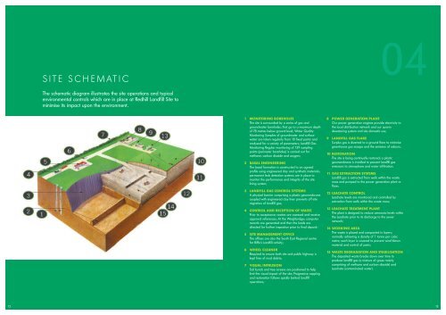
SITE SCHEMATIC04The schematic diagram illustrates the site operations and typicalenvironmental controls which are in place at <strong>Redhill</strong> Landfill Site tominimise its impact upon the environment.1 MONITORING BOREHOLESThe site is surrounded by a series of gas andgroundwater boreholes; that go to a maximum depthof 78 metres below ground level; Water QualityMonitoring Samples of groundwater and surfacewater are taken regularly from 18 fixed points andanalysed for a variety of parameters; Landfill GasMonitoring Regular monitoring of 139 samplingpoints (perimeter boreholes) is carried out formethane; carbon dioxide and oxygen;2 BASAL ENGINEERINGThe basal formation is constructed to an agreedprofile using engineered clay and synthetic materials;permanent leak detection systems are in place tomonitor the performance and integrity of the sitelining system;3 LANDFILL GAS CONTROL SYSTEMSA physical barrier comprising a plastic geomembranecoupled with engineered clay liner prevents off-sitemigration of landfill gas;4 CONTROL AND RECEPTION OF WASTEPrior to acceptance; wastes are assessed and receiveapproval references; At the Weighbridge; computerrecords are generated and then the loads aredirected for further inspection prior to final deposit;5 SITE MANAGEMENT OFFICEThe offices are also the South East Regional centrefor <strong>Biffa</strong>'s Landfill activity;6 WHEEL CLEANERRequired to ensure both site and public highway iskept free of mud debris;7 VISUAL INTRUSIONSoil bunds and tree screens are positioned to helplimit the visual impact of the site; Progressive cappingand restoration follows quickly behind landfilloperations;8 POWER GENERATION PLANTOur power generation engines provide electricity tothe local distribution network and our quarrydewatering system and site domestic use;9 LANDFILL GAS FLARESurplus gas is diverted to a ground flare to minimisegreenhouse gas escape and the emission of odours;10 RESTORATIONThe site is being continually restored; a plasticgeomembrane is installed to prevent landfill gasemissions to atmosphere and water infiltration;11 GAS EXTRACTION SYSTEMSLandfill gas is extracted from wells within the wastemass and pumped to the power generation plant orflare;12 LEACHATE CONTROLLeachate levels are monitored and controlled byextraction from wells within the waste mass;13 LEACHATE TREATMENT PLANTThe plant is designed to reduce ammonia levels withinthe Leachate prior to its discharge to the sewernetwork;14 WORKING AREAThe waste is placed and compacted in layers;normally achieving a density of 1 tonne per cubicmetre; each layer is covered to prevent wind blownmaterial and control of pests;15 WASTE DEGRADATION AND STABILISATIONThe deposited waste breaks down over time toproduce landfill gas (a mixture of gases mainlycomprising of methane and carbon dioxide) andLeachate (contaminated water).1213