Flow Charting and Block Diagramming Techniques - All about the ...
Flow Charting and Block Diagramming Techniques - All about the ...
Flow Charting and Block Diagramming Techniques - All about the ...

Create successful ePaper yourself
Turn your PDF publications into a flip-book with our unique Google optimized e-Paper software.
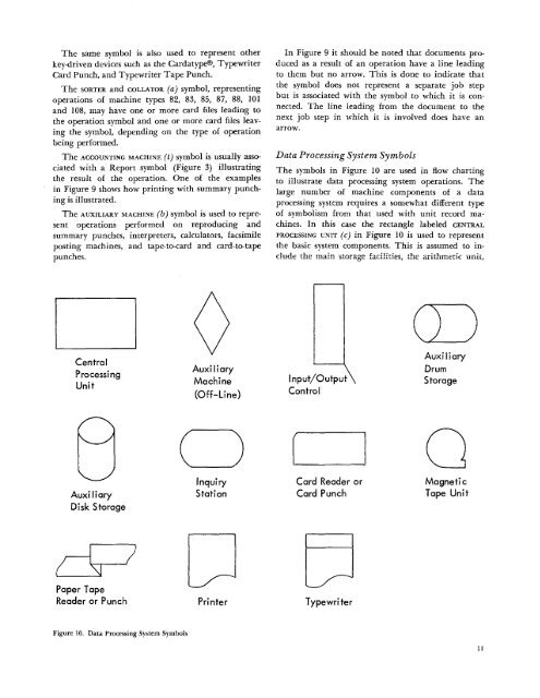
The same symbol is also used to represent o<strong>the</strong>rkey-driven devices such as <strong>the</strong> Cardatype®, TypewriterCard Punch, <strong>and</strong> Typewriter Tape Punch.The SORTER <strong>and</strong> COLLATOR (a) symbol, representingoperations of machine types 82, 83, 85, 87, 88, 101<strong>and</strong> 108, may have one or more card files leading to<strong>the</strong> operation symbol <strong>and</strong> one or more card files leaving<strong>the</strong> symbol, depending on <strong>the</strong> type of operationbeing performed.The ACCOUNTING MACHINE (t) symbol is usually associatedwith a Report symbol (Figure 3) illustrating<strong>the</strong> result of <strong>the</strong> operation. One of <strong>the</strong> examplesin Figure 9 shows how printing with summary punchingis illustrated.The AUXILIARY MACHINE (b) symbol is used to representoperations performed on reproducing <strong>and</strong>summary punches, interpreters, calculators, facsimileposting machines, <strong>and</strong> tape-to-card <strong>and</strong> card-to-tapepunches.In Figure 9 it should be noted that documents producedas a result of an operation have a line leadingto <strong>the</strong>m but no arrow. This is done to indicate that<strong>the</strong> symbol does not represent a separate job stepbut is associated with <strong>the</strong> symbol to which it is connected.The line leading from <strong>the</strong> document to <strong>the</strong>next job step in which it is involved does have anarrow.Data Processing System SymbolsThe symbols in Figure 10 are used in flow chartingto illustrate data processing system operations. Thelarge number of machine components of a dataprocessing system requires a somewhat different typeof symbolism from that used with unit record machines.In this case <strong>the</strong> rectangle labeled CENTRALPROCESSING UNIT (c) in Figure 10 is used to represent<strong>the</strong> basic system components. This is assumed to include<strong>the</strong> main storage facilities, <strong>the</strong> arithmetic unit,CentralProcessingUnitAuxiliaryMachine(Off-Line)Input/Outpui\,ControlAuxiliaryDrumStorageInquiryAuxi I iary StationDisk StorageCard Reader orCard PunchPaper TapeReader or Punch PrinterTypewriterFigure 10. Data Processing System Symbols11