Flow Charting and Block Diagramming Techniques - All about the ...
Flow Charting and Block Diagramming Techniques - All about the ...
Flow Charting and Block Diagramming Techniques - All about the ...

You also want an ePaper? Increase the reach of your titles
YUMPU automatically turns print PDFs into web optimized ePapers that Google loves.
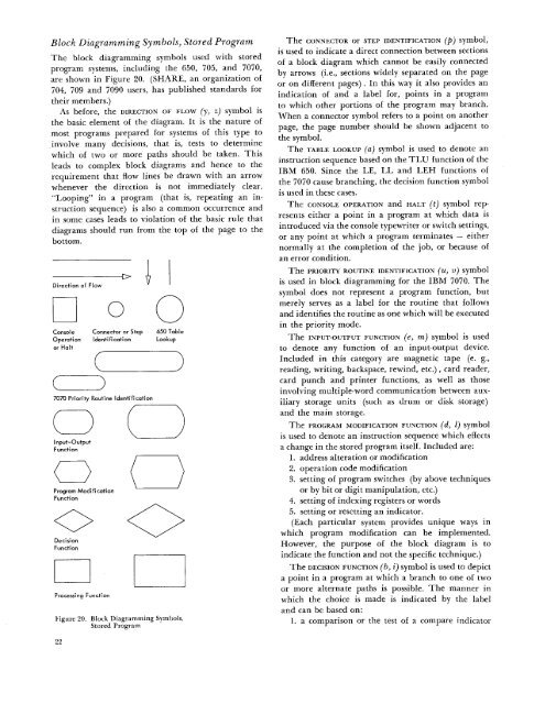
<strong>Block</strong> <strong>Diagramming</strong> Symbols, Stored ProgramThe block diagramming symbols used with storedprogram systems, including <strong>the</strong> 650, 705, <strong>and</strong> 7070,are shown in Figure 20. (SHARE, an organization of704, 709 <strong>and</strong> 7090 users, has published st<strong>and</strong>ards for<strong>the</strong>ir members.)As before, <strong>the</strong> DIRECTION OF FLOW (y, z) symbol is<strong>the</strong> basic element of <strong>the</strong> diagram. It is <strong>the</strong> nature ofmost programs prepared for systems of this type toinvolve many decisions, that is, tests to determinewhich of two or more paths should be taken. Thisleads to complex block diagrams <strong>and</strong> hence to <strong>the</strong>requirement that flow lines be drawn with an arrowwhenever <strong>the</strong> direction is not immediately clear."Looping" in a program (that is, repeating an instructionsequence) is also a common occurrence <strong>and</strong>in some cases leads to violation of <strong>the</strong> basic rule thatdiagrams should run from <strong>the</strong> top of <strong>the</strong> page to <strong>the</strong>bottom.Direction of <strong>Flow</strong>Console Connector or StepOperation Identificationor HaltProcessing Function0650 TableLookupFigure 20. <strong>Block</strong> <strong>Diagramming</strong> Symbols,Stored ProgramThe CONNECTOR Or STEP IDENTIFICATION (p) symbol,is used to indicate a direct connection between sectionsof a block diagram which cannot be easily connectedby arrows (i.e., sections widely separated on <strong>the</strong> pageor on different pages) . In this way it also provides anindication of <strong>and</strong> a label for, points in a programto which o<strong>the</strong>r portions of <strong>the</strong> program may branch.When a connector symbol refers to a point on ano<strong>the</strong>rpage, <strong>the</strong> page number should be shown adjacent to<strong>the</strong> symbol.The TABLE LOOKUP (a) symbol is used to denote aninstruction sequence based on <strong>the</strong> TLU function of <strong>the</strong>IBM 650. Since <strong>the</strong> LE, LL <strong>and</strong> LEH functions of<strong>the</strong> 7070 cause branching, <strong>the</strong> decision function symbolis used in <strong>the</strong>se cases.The CONSOLE OPERATION <strong>and</strong> HALT (t) symbol representsei<strong>the</strong>r a point in a program at which data isintroduced via <strong>the</strong> console typewriter or switch settings,or any point at which a program terminates — ei<strong>the</strong>rnormally at <strong>the</strong> completion of <strong>the</strong> job, or because ofan error condition.The PRIORITY ROUTINE IDENTIFICATION (tt, v) symbolis used in block diagramming for <strong>the</strong> IBM 7070. Thesymbol does not represent a program function, butmerely serves as a label for <strong>the</strong> routine that follows<strong>and</strong> identifies <strong>the</strong> routine as one which will be executedin <strong>the</strong> priority mode.The INPUT-OUTPUT FUNCTION (e, m) symbol 1S usedto denote any function of an input-output device.Included in this category are magnetic tape (e. g.,reading, writing, backspace, rewind, etc.) , card reader,card punch <strong>and</strong> printer functions, as well as thoseinvolving multiple-word communication between auxiliarystorage units (such as drum or disk storage)<strong>and</strong> <strong>the</strong> main storage.The PROGRAM MODIFICATION FUNCTION (d, 1) symbolis used to denote an instruction sequence which effectsa change in <strong>the</strong> stored program itself. Included are:1. address alteration or modification2. operation code modification3. setting of program switches (by above techniquesor by bit or digit manipulation, etc.)4. setting of indexing registers or words5. setting or resetting an indicator.(Each particular system provides unique ways inwhich program modification can be implemented.However, <strong>the</strong> purpose of <strong>the</strong> block diagram is toindicate <strong>the</strong> function <strong>and</strong> not <strong>the</strong> specific technique.)The DECISION FUNCTION (b, i) symbol is used to depicta point in a program at which a branch to one of twoor more alternate paths is possible. The manner inwhich <strong>the</strong> choice is made is indicated by <strong>the</strong> label<strong>and</strong> can be based on:1. a comparison or <strong>the</strong> test of a compare indicator22