Flow Charting and Block Diagramming Techniques - All about the ...
Flow Charting and Block Diagramming Techniques - All about the ...
Flow Charting and Block Diagramming Techniques - All about the ...
Create successful ePaper yourself
Turn your PDF publications into a flip-book with our unique Google optimized e-Paper software.
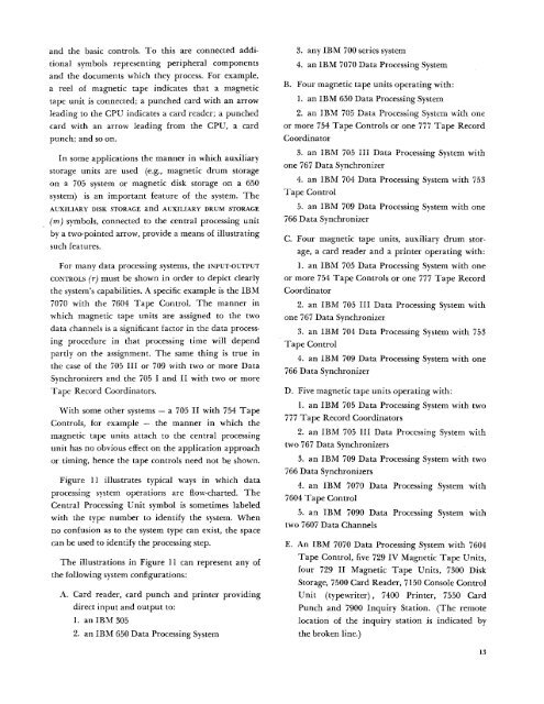
<strong>and</strong> <strong>the</strong> basic controls. To this are connected additionalsymbols representing peripheral components<strong>and</strong> <strong>the</strong> documents which <strong>the</strong>y process. For example,a reel of magnetic tape indicates that a magnetictape unit is connected; a punched card with an arrowleading to <strong>the</strong> CPU indicates a card reader; a punchedcard with an arrow leading from <strong>the</strong> CPU, a cardpunch; <strong>and</strong> so on.In some applications <strong>the</strong> manner in which auxiliarystorage units are used (e.g., magnetic drum storageon a 705 system or magnetic disk storage on a 650system) is an important feature of <strong>the</strong> system. TheAUXILIARY DISK STORAGE <strong>and</strong> AUXILIARY DRUM STORAGE(m) symbols, connected to <strong>the</strong> central processing unitby a two-pointed arrow, provide a means of illustratingsuch features.For many data processing systems, <strong>the</strong> INPUT-OUTPUTCONTROLS (r) must be shown in order to depict clearly<strong>the</strong> system's capabilities. A specific example is <strong>the</strong> IBM7070 with <strong>the</strong> 7604 Tape Control. The manner inwhich magnetic tape units are assigned to <strong>the</strong> twodata channels is a significant factor in <strong>the</strong> data processingprocedure in that processing time will dependpartly on <strong>the</strong> assignment. The same thing is true in<strong>the</strong> case of <strong>the</strong> 705 III or 709 with two or more DataSynchronizers <strong>and</strong> <strong>the</strong> 705 I <strong>and</strong> II with two or moreTape Record Coordinators.With some o<strong>the</strong>r systems — a 705 II with 754 TapeControls, for example — <strong>the</strong> manner in which <strong>the</strong>magnetic tape units attach to <strong>the</strong> central processingunit has no obvious effect on <strong>the</strong> application approachor timing, hence <strong>the</strong> tape controls need not be shown.Figure 11 illustrates typical ways in which dataprocessing system operations are flow-charted. TheCentral Processing Unit symbol is sometimes labeledwith <strong>the</strong> type number to identify <strong>the</strong> system. Whenno confusion as to <strong>the</strong> system type can exist, <strong>the</strong> spacecan be used to identify <strong>the</strong> processing step.The illustrations in Figure 11 can represent any of<strong>the</strong> following system configurations:A. Card reader, card punch <strong>and</strong> printer providingdirect input <strong>and</strong> output to:1. an IBM 3052. an IBM 650 Data Processing System3. any IBM 700 series system4. an IBM 7070 Data Processing SystemB. Four magnetic tape units operating with:1. an IBM 650 Data Processing System2. an IBM 705 Data Processing System with oneor more 754 Tape Controls or one 777 Tape RecordCoordinator3. an IBM 705 III Data Processing System withone 767 Data Synchronizer4. an IBM 704 Data Processing System with 753Tape Civiitrvi5. an IBM 709 Data Processing System with one766 Data SynchronizerC. Four magnetic tape units, auxiliary drum storage,a card reader <strong>and</strong> a printer operating with:1. an IBM 705 Data Processing System with oneor more 754 Tape Controls or one 777 Tape RecordCoordinator2. an IBM 705 III Data Processing System withone 767 Data Synchronizer3. an IBM 704 Data Processing System with 753Tape Control4. an IBM 709 Data Processing System with one766 Data SynchronizerD. Five magnetic tape units operating with:1. an IBM 705 Data Processing System with two777 Tape Record Coordinators2. an IBM 705 III Data Processing System withtwo 767 Data Synchronizers3. an IBM 709 Data Processing System with two766 Data Synchronizers4. an IBM 7070 Data Processing System with7604 Tape Control5. an IBM 7090 Data Processing System withtwo 7607 Data ChannelsE. An IBM 7070 Data Processing System with 7604Tape Control, five 729 IV Magnetic Tape Units,four 729 II Magnetic Tape Units, 7300 DiskStorage, 7500 Card Reader, 7150 Console ControlUnit (typewriter) , 7400 Printer, 7550 CardPunch <strong>and</strong> 7900 Inquiry Station. (The remotelocation of <strong>the</strong> inquiry station is indicated by<strong>the</strong> broken line.)13


