Design For Deconstruction - US Environmental Protection Agency
Design For Deconstruction - US Environmental Protection Agency
Design For Deconstruction - US Environmental Protection Agency

You also want an ePaper? Increase the reach of your titles
YUMPU automatically turns print PDFs into web optimized ePapers that Google loves.
DESIGN FOR<br />
DECONSTRUCTION
Although the information in this document has been funded<br />
in part by the United States <strong>Environmental</strong> <strong>Protection</strong> <strong>Agency</strong><br />
under assistance agreement X1-96912701 to Chartwell School,<br />
it has not gone through the <strong>Agency</strong>’s publications review<br />
or peer review process and, therefore, may not necessarily<br />
reflect the views of the <strong>Agency</strong> and no official endorsement<br />
should be inferred.<br />
contents<br />
1 Overview<br />
2 Lessons from the Field<br />
3 DFD Principles and Strategies<br />
4 Setting Priorities<br />
5 Chartwell School Case Study
Preface<br />
The ultimate goal of the <strong>Design</strong> for <strong>Deconstruction</strong> (DfD) movement<br />
is to responsibly manage end-of-life building materials to minimize<br />
consumption of raw materials. By capturing materials removed during<br />
building renovation or demolition and finding ways to reuse them in<br />
another construction project or recycle them into a new product, the<br />
overall environmental impact of end-of-life building materials can be<br />
reduced. Architects and engineers can contribute to this movement<br />
by designing buildings that facilitate adaptation and renovation. This<br />
handbook presents an overview of basic <strong>Design</strong> for <strong>Deconstruction</strong><br />
principles, and outlines the implementation of these principles in the<br />
design of Chartwell School in Seaside, California.<br />
OVERVIEW DESIGN FOR DISASSEMBLY<br />
5
1. Overview<br />
Most accounts of deconstruction begin with the amount<br />
of building debris that goes to the landfill. In part this is<br />
simply because debris is such an immediate, visible part of<br />
our experience. What was yesterday a functional building,<br />
is today a worthless pile of rubble sitting on the site for all<br />
to see. Even a modest kitchen remodel has the ever-present<br />
trash dumpster, as big as the kitchen itself, parked proudly<br />
in front of the house. As seen from the job site, the flow of<br />
materials is very simple, materials come from Home Depot,<br />
they’re assembled into buildings, and the waste—whether<br />
construction, renovation, or demolition—goes into the<br />
dumpster. This simple linear view of materials flow is<br />
deeply ingrained from our everyday personal experience.<br />
If we zoom out from the job site and look at the<br />
broader flow of materials, we all understand that downstream<br />
from the jobsite, debris in dumpsters goes mostly<br />
to landfills. And upstream from the jobsite, raw materials<br />
must first be mined or logged, then refined, processed and<br />
manufactured prior to showing up at our local supplier.<br />
In “The Ecology of Building Materials” Bjorn Berge illustrates<br />
this in a simple diagram: resources are extracted from<br />
the earth, refined and manufactured into useable materials,<br />
assembled into buildings, and eventually returned to<br />
the earth via landfills when the buildings are remodeled or<br />
demolished.<br />
This may sound obvious, but overwhelmingly our<br />
everyday experience is with the downstream side. While<br />
we have all experienced trash, few people have really seen<br />
and experienced industrial mining, logging, and refining,<br />
so it remains less tangible, less real. As a result, we see<br />
debris as a downstream “waste” management issue.<br />
However, the real benefits of deconstruction --including<br />
<strong>Design</strong>ing for <strong>Deconstruction</strong> (DfD)--is about closing<br />
the loop of resource use. It is about reusing these “waste”<br />
resources to avoid logging or mining new virgin resources<br />
from our ecosystems. <strong>Design</strong>ing for <strong>Deconstruction</strong> is<br />
about designing in such a way that these resources can be<br />
economically recovered and reused. In contrast to the conventional<br />
linear model of extraction, use, and landfilling,<br />
DfD envisions a closed cycle of use and reuse.<br />
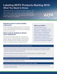
Figure 1.1 Conventional resource flows start with extraction from the earth, and eventually return those<br />
resources to the earth via landfills. DfD encourages the economical reuse or recycling of those resources to<br />
avoid additional logging or mining of virgin resources. Adapted from Bjorn Berge, “The Ecology of Building<br />
Materials”<br />
7
OVERVIEW DESIGN FOR DISASSEMBLY<br />
8<br />
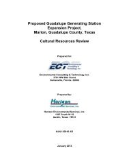
Such a closed loop material cycle is illustrated below<br />
in figure 1.2 for the metal Lead. This is quite an impressive<br />
cycle, with new Lead production from virgin ore on the<br />
upstream end, and wasted Lead on the downstream end,<br />
both being small percentages of the total material flow.<br />
Figure 1.2 A closed loop material cycle for the metal lead<br />
But Lead is easy, buildings are not. The vast majority<br />
of lead is in car batteries. They are too heavy to carry<br />
around, so you get it changed at a garage where they keep<br />
your old battery for recycling. The Lead is relatively easy<br />
to extract from the battery case and is readily recycled, it<br />
has a low melting point reducing energy costs and environmental<br />
impacts, and it’s a valuable commodity.
Buildings on the other hand are large, stationary, complex<br />
assemblies of relatively low value commodities. These<br />
materials are often difficult to separate, and many are not<br />
readily recycled. The value of a building is not so much<br />
in the materials themselves, but in the functional traits<br />
of shelter and the like that they provide when assembled<br />
together. Because of this, these materials retain more value<br />
when deconstructed and reused than when recycled. Much<br />
of what is called recycling is actually the down-cycling of a<br />
material to a lower grade use. Concrete can be “recycled”,<br />
but only as low value aggregate, wood debris can be ground<br />
up for wood fiber or mulch, but thereby loses its most<br />
valuable properties.<br />
If we look again at the resource flow diagram in figure<br />
1.1, the smaller and tighter that this cycle of resource use is,<br />
the better. Each step along the way typically requires additional<br />
resources such as energy, transportation, or additional<br />
materials. If we can recover components and materials from<br />
buildings for reuse, this eliminates these additional inputs.<br />
To understand why this matters, one needs to understand<br />
the staggering scope of material flows in construction.<br />
According to the <strong>US</strong> Geological Survey, an estimated<br />
60% of materials flow in the <strong>US</strong> economy (excluding food<br />
and fuel) is consumed by the construction industry. Construction<br />
is one of the largest users of timber, and so shares<br />
responsibility for the logging impacts in our forests. Buildings<br />
are among the largest consumers of copper and steel,<br />
and so share responsibility for these mining and refining<br />
impacts. Buildings are the largest consumer of polyvinyl<br />
chloride (PVC), and so must acknowledge their share of its<br />
pollution and health impacts.<br />
Virtually every step in a material cycle requires energy<br />
inputs, for extraction, refining, transportation, and fabrication;<br />
and along with the energy comes CO2 emissions, the<br />
primary greenhouse gas causing climate change. Manufacturing<br />
cement alone emits about 7% of global carbon<br />
emissions. It takes 110 tons of copper ore to produce a<br />
single ton of copper, with major energy inputs required to<br />
move this much earth and refine it into a pure metal. And<br />
moving thousands of tons of materials from their source<br />
to a construction site requires major transportation inputs.<br />
Many of these impacts can be avoided or reduced by reusing<br />
materials in a manner that preserves the embodied<br />
energy and carbon already invested in those materials.<br />
As these huge material flows work their way slowly through<br />
buildings via renovation and demolition, we see that<br />
Construction and Demolition debris (C&D debris) currently<br />
makes up 25-30% of all solid waste produced in the<br />
United States, over 136 million tons in 1996. Discarding<br />
these materials rather than reusing them will continue to<br />
require extraction of huge quantities of new materials and<br />
the associated impacts on our ecosystems. We need a new<br />
mental model that clearly envisions these “wastes” as valuable<br />
resources harvested from existing buildings and used<br />
to build new ones.<br />
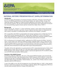
Demolition<br />
48%<br />
Construction<br />
8%<br />
Rennovation<br />
44%<br />
Non-Residential Residential<br />
57% 43%<br />
Figure 1.3 Construction & Demolition Debris<br />
Characteristic of building-Related Construction and Demolition in the United<br />
States, U.S EPA, 1998.<br />
OVERVIEW DESIGN FOR DISASSEMBLY 9
OVERVIEW DESIGN FOR DISASSEMBLY<br />
10<br />
The overwhelming majority of these resources are<br />
generated not from new construction, but from renovation<br />
and demolition. The challenge is that the buildings were<br />
not designed to allow these materials to be readily recovered.<br />
This is the task of <strong>Design</strong>ing for <strong>Deconstruction</strong>, to figure<br />
out how to put buildings together so that they can be economically<br />
taken apart and the components reused.<br />
By easing deconstruction and separation of components<br />
within buildings, it facilitates the development of closed loop<br />
material cycles. It improves the economics for manufacturers<br />
for innovative approaches such as products as “services”<br />
that are leased over time, or material take-back systems such<br />
as Armstrong’s impressive closed loop recycling of ceiling<br />
tiles. And since deconstruction is a much cleaner form of<br />
dismantling than traditional mechanical demolition, local<br />
site environmental impacts such as noise, dust, and possible<br />
hazardous material releases are reduced.<br />
There have been many elegant specialty construction<br />
systems designed over the years to encourage mass production,<br />
modular design, or the assembly of buildings from<br />
standardized parts and connectors. <strong>For</strong> a range of reasons,<br />
these whole-systems approaches have had limited success in<br />
the market. The future may hold great promise for a completely<br />
new system of construction. But the strategy in this<br />
handbook is to work with current common construction<br />
systems, optimizing them for deconstruction, rather than<br />
creating another new system.<br />
Adaptability and Ease of Maintenance<br />
<strong>Design</strong> for <strong>Deconstruction</strong> is often thought of only as it<br />
applies to a building at the end of its life. But <strong>Design</strong> for<br />
<strong>Deconstruction</strong> (DfD) is just one term among a number of<br />
<strong>Design</strong> for “_____”, such as <strong>Design</strong> for -Adaptation, -Disassembly,<br />
-Reuse, -Recycling, -Reparability, -Product recovery,<br />
and -End-of-life. In fact some of the greatest benefits<br />
of <strong>Design</strong> for <strong>Deconstruction</strong> are during a building’s lifetime,<br />
or actually extend a building’s useful life.<br />
By making building components easier and faster to<br />
remove, it is easier to adapt or change the building to meet<br />
evolving functions over its lifetime, the concept has been<br />
called Life Cycle building. This reduces the cost of renovation<br />
and extends a building’s life by making it economic to<br />
remodel. Extending the useful life of an entire building is<br />
the highest form of salvage and reuse.<br />
Some architects do consider alternate future functions<br />
that a building may have, and try to allow flexibility for this<br />
in their design. Important considerations include choosing<br />
a structural system that allows spaces to be reconfigured, or<br />
locating inflexible plumbing, stair or elevator cores to provide<br />
future flexibility.<br />
Providing access and pathways for changes to building<br />
utilities and infrastructure can greatly simplify modifications<br />
or maintenance for a building. Utilities, such as<br />
telecom, electrical, and mechanical systems, are some of<br />
the most frequent components needing maintenance or<br />
upgrades. If these systems are accessible, whether exposed,<br />
above an accessible ceiling, or in an attic or crawl space,<br />
the speed and cost of changes is significantly reduced. If<br />
a component or material is designed for removal, it also<br />
facilitates access to utilities it may conceal.<br />
Finally, DfD preserves some of the social and historical<br />
“content” of recovered materials and the building fabric<br />
which housed them. Like an industrial building converted<br />
to lofts, or salvaged lumber showing years of character,<br />
these materials have a history and tell a story that connects<br />
people to another age. Other components like a vintage<br />
fireplace mantle, stair-rail, or stained glass windows recall<br />
the culture and craft of the designers who made them.<br />
High quality, well-designed components such as these are<br />
highly valued and often recovered for reuse. The real challenge<br />
of DfD is to expand the range of materials and components<br />
beyond a few specialty items that can be cherrypicked<br />
out of a building, to the components and materials<br />
that make up the bulk of the building.
2. Lessons from the Field<br />
<strong>For</strong>t Ord Barracks <strong>Deconstruction</strong><br />
Wood Waste Diversion,<br />
John Stephens, Jbsfortord@aol.com<br />
In 2004 Wood Waste Diversion deconstructed this barracks<br />
building at the decommissioned <strong>For</strong>t Ord in California.<br />
These are simple buildings with lots of valuable lumber,<br />
and few finish materials or adhesives to complicate deconstruction.<br />
Hazardous materials can be one of the biggest<br />
challenges, in this case asbestos and lead based paint.<br />
Figure 2.1 Typical <strong>For</strong>t Ord Barracks building to be deconstructed, part of the “urban forest” that is<br />
being harvested for new construction projects<br />
11
LESSONS FROM THE FIELD DESIGN FOR DISASSEMBLY<br />
12<br />
Figure 2.2 Roof is removed to ground level where it is safer and faster<br />
to deconstruct<br />
Figure 2.3 Roof is separated into planes of rafters & sheathing
Figure 2.4 Using a “snowplow” to remove asphalt roof shingles. Finding<br />
fast, economical tools and methods for <strong>Deconstruction</strong> is a key step to<br />
making it standard practice.<br />
Figure 2.5 Removing sheathing from joists, the work is elevated for convenience<br />
LESSONS FROM THE FIELD DESIGN FOR DISASSEMBLY<br />
13
LESSONS FROM THE FIELD DESIGN FOR DISASSEMBLY<br />
14<br />
Figure 2.6 Removing joists from sheathing with custom made pry bars<br />
Figure 2.7 Removing studs from sheathing using the Drive-By method
Figure 2.8 Pneumatic de-nail station with the “Nail Kicker”<br />
(www.nailkicker.com)<br />
Figure 2.9 Reclaimed old growth lumber, denailed and planed, ready for<br />
new construction.<br />
LESSONS FROM THE FIELD DESIGN FOR DISASSEMBLY<br />
15
LESSONS FROM THE FIELD DESIGN FOR DISASSEMBLY<br />
16<br />
Figure 2.10 Reclaimed wood is reused for a new ceiling at the Cal State University Visitors Center,<br />
one of the new institutions at the former <strong>For</strong>t Ord.
Mobile Lead Based Paint Removal System<br />
Wood Waste Diversion<br />
John Stephens JBSfortord@aol.com<br />
Driving his kids to school at <strong>For</strong>t Ord everyday, John Stephens<br />
would look at the hundreds of abandoned barracks<br />
and think what a waste of beautiful old growth lumber.<br />
Wouldn’t it be better to salvage and reuse all this wood?<br />
One of main stumbling blocks was it was covered in lead<br />
based paint. John knew a planer was the most efficient<br />
way to remove the paint, the problem was capturing all the<br />
lead dust. So he set out to build an “airtight” trailer that<br />
would capture all the hazardous planer shavings. Working<br />
with Stan Cook at the <strong>For</strong>t Ord Reuse Authority and<br />
funded by an EPA grant for deconstruction, he designed<br />
and built the Mobile Lead Based Paint (LBP) Removal System<br />
(patent pending). It has undergone extensive testing<br />
to ensure no lead is released into the atmosphere, and been<br />
certified by the California Air Resources Board. John now<br />
leases the equipment to large projects around the country.<br />
Figure 2.11 Trailer is parked at the deconstruction site, it is negatively<br />
pressurized to contain lead paint dust.<br />
LESSONS FROM THE FIELD DESIGN FOR DISASSEMBLY<br />
17
LESSONS FROM THE FIELD DESIGN FOR DISASSEMBLY<br />
18<br />
Figure 2.12 Recovered lead painted siding is fed into the planer on<br />
one side of the trailer<br />
Figure 2.13 Clean old growth Douglas Fir comes out the other side.
Figure 2.14 Clean, salvaged Douglas Fir, ready for another home.<br />
LESSONS FROM THE FIELD DESIGN FOR DISASSEMBLY<br />
19
3. DFD Principles and Strategies<br />
What determines if buildings get deconstructed?<br />
<strong>Deconstruction</strong> is often discussed primarily as a strategy<br />
to meet environmental goals, but it can meet social and<br />
economic goals as well. There must be an infrastructure of<br />
contractors skilled in deconstructing buildings, the cost of<br />
deconstruction and the recovered materials must be competitive<br />
with alternatives, and there must be a market for<br />
the recovered materials. Some of the key factors determining<br />
if buildings are deconstructed include:<br />
• The local cost of landfill tipping fees<br />
• The local cost of labor and equipment<br />
• The ease of disassembly which affects labor cost<br />
• The value of the materials recovered<br />
• Having adequate time available for deconstruction<br />
Landfill tipping fees - charges for depositing waste on<br />
a landfill - vary greatly by region from less than $10/ton to<br />
over $100/ton in states like Vermont or California. In areas<br />
with high tipping fees, deconstructing buildings can avoid<br />
substantial tipping fees, which can help offset the additional<br />
labor needed to disassemble the building. Labor and equipment<br />
costs also vary greatly by region, and significantly affect<br />
the economics of labor-intensive deconstruction.<br />
The value of the materials recovered is also a key<br />
factor. The booming salvaged wood market has spurred<br />
increased competition for buildings containing large timbers<br />
or high quality old-growth lumber. The value of this<br />
lumber can command premium prices, up to $12/board<br />
foot. Many homeowners are willing to pay a premium for<br />
recycled wood that has a story and “character.” Salvaged<br />
components such as antique fireplace surrounds, light<br />
fixtures, hardware, and other ornamental pieces can be<br />
shipped to a national market and command high prices,<br />
as a quick search on E-Bay will show. The internet can<br />
facilitate connecting buyer and seller through local bulletin<br />
boards or services like the California Materials Exchange<br />
(www.ciwmb.ca.gov/calMAX). The value of many larger<br />
recovered resources depends on the robustness of the local<br />
recovered materials markets. Chicago has a very active<br />
market in salvaged bricks due to the large number of brick<br />
buildings with lime mortar there. The West Coast has<br />
dozens of salvaged wood dealers supplied by dismantled<br />
structures built from the forest resources of an earlier era.<br />
<strong>Design</strong>ers can increase the likelihood that a building will be<br />
deconstructed if they choose quality materials that will have<br />
a high value in the future.<br />
<strong>Deconstruction</strong> does take longer than demolishing a<br />
building with heavy equipment, if this is not considered, it<br />
likely will not happen. If demolition of an existing structure<br />
is part of a construction contract for a new building,<br />
the contractor will often want it down as quickly as possible<br />
to start on the new project and meet that schedule. It<br />
often makes sense to issue a separate contract prior to and<br />
separate from the new work to relieve some of the schedule<br />
pressure. If the building to be demolished is in use<br />
or generating revenue from a lease, these can present real<br />
obstacles.<br />
The ease and speed of deconstruction is a key factor<br />
that this Handbook most directly addresses. How can<br />
architects, engineers, and builders put buildings together<br />
that are easier to take apart? Do the fastening methods<br />
allow disassembly, and are these connections accessible?<br />
Are there too many materials or are they assembled in a<br />
complex, intertwined manner? Are hazardous materials<br />
intermixed with the valuable ones? Are the components<br />
visible or identifiable on existing drawings? Are glues and<br />
composite materials avoided? The designers and builders of<br />
our structures have a major impact on how readily they can<br />
be deconstructed. Often a simple mental shift to just think<br />
about the ease of disassembly during design and construction<br />
reveals numerous strategies that can be easily adopted.<br />
<strong>Deconstruction</strong> strategies:<br />
• Maximize clarity and simplicity<br />
• Minimize building complexity<br />
• Minimize different types of materials<br />
• Minimize number of components (fewer, larger elements)<br />
• Minimize number of fasteners (fewer, stronger fasteners)<br />
• Use mechanical fasteners in lieu of sealants and adhesives<br />
• Simplify connections<br />
• Make connections visible/accessible<br />
• Separate building layers or systems<br />
• Disentangle utilities from structure<br />
• Use materials worth recovering<br />
• Minimize toxic materials<br />
• Minimize composite materials<br />
• Use of modular building components/assemblies<br />
• Provide access to components/assemblies (windows, etc)<br />
• Provide access or tie-offs for work at height<br />
• Accessible information:<br />
• Construction drawings & details<br />
• Identification of materials and components<br />
• Structural properties<br />
21
DFD PRINCIPLES AND STRATEGIES DESIGN FOR DISASSEMBLY<br />
22<br />
Materials, Assemblies, and Building Systems<br />
<strong>Design</strong> for deconstruction suggests careful thought about<br />
how materials, assemblies, and building systems interconnect.<br />
The following section describes important DfD<br />
principles – and questions to ask – at these three building<br />
levels.<br />
Materials<br />
Precautionary materials selection<br />
Use materials worth or feasible for recovery<br />
Minimize number of different materials<br />
Avoid composites of dissimilar materials<br />
Minimize toxic materials<br />
In general, materials should be selected with caution.<br />
Abating hazardous materials can greatly increase cost, as<br />
industry experience with asbestos and lead paint have made<br />
very clear. There are good sources of information to assist<br />
architects and contractors in avoiding potentially hazardous<br />
materials, including GreenSpec, which provides a comprehensive<br />
list of carefully reviewed materials. If hazardous<br />
materials are required for performance reasons, consider<br />
tagging or identifying them so they can be properly handled<br />
at the end of their life.<br />
Using fewer materials also simplifies deconstruction.<br />
Automobile dashboards used to be complex assemblies<br />
of numerous materials that made recycling impractical.<br />
Newer technology allows the use of a single resin for an<br />
entire assembly that can be readily recycled. DfD suggests<br />
that designers consider if possibly the same architectural<br />
effect or performance can be achieved by using fewer material<br />
types, or the same material in different ways? If more<br />
material types are necessary, the interface between materials<br />
should be carefully considered. When possible, consider<br />
the use of solid materials in lieu of composites of dissimilar<br />
materials, as composites complicate the separation of individual<br />
materials for reuse.<br />
Assemblies<br />
Minimize number of components (fewer, larger elements)<br />
Minimize number of fasteners (fewer, stronger fasteners)<br />
Use mechanical fasteners in lieu of sealants and adhesives<br />
Simplify connections<br />
Make connections visible/accessible<br />
Separate building layers or systems<br />
Disentangle utilities from structure<br />
Defined as a collection of parts fitted together into a<br />
complete structure, assemblies are the building blocks of<br />
architecture. They dictate how materials and components<br />
come together. As such, design for deconstruction encompasses<br />
the field of disassembly. Only the optimal number<br />
of fastenings should be used, and the design process should<br />
question: can the assembly be structurally supported with<br />
fewer but stronger fasteners? Does consideration for the<br />
location of fasteners yield a more economical solution? At<br />
the material level, where and how do fasteners affect potential<br />
for reuse? Irreversible fasteners to avoid include glues<br />
and chemicals, as they damage materials being removed.<br />
Instead, consider the use of screws, bolts, and mechanical<br />
connections. Disassembly is simplified when there is clarity,<br />
not complexity, in how fasteners are used.<br />
<strong>Design</strong> should also consider access to subassemblies,<br />
particularly those which need to be maintained, repaired, or<br />
modified on a regular basis. Access to a subassembly should<br />
not degrade materials or assemblies “above” it, such as not<br />
having to cut and patch drywall and stucco to replace a<br />
window. Connections should be simplified, readily accessible,<br />
and where possible exposed to serve as everyday clues<br />
as to the deconstruction process, or at least allow users to<br />
formulate questions about assembly and disassembly.<br />
Modularity and prefabrication can promote reuse and<br />
recycling at a larger scale – whether modules of assemblies<br />
or their component materials. However, modules and<br />
components should be dimensioned for reuse. It only<br />
makes sense to modularize a particular assembly if it makes<br />
construction and deconstruction easier. And if modularity<br />
complicates assembly or if it involves the modularization of<br />
overly specific pieces, then it may in fact force creative reuse<br />
at best.
Building Systems<br />
Consider building system relationships, efficiency, and articulation<br />
Consider independent (self-supporting) assemblies<br />
Stud-framed construction has traditionally been a quickand-easy-to-build<br />
assembly performing multiple functions:<br />
load and shear bearing walls, exterior envelope, interior<br />
partition, and electrical and plumbing chase, to name a<br />
few. With so many roles, building systems are often modified<br />
to accommodate one another within a 6” thick wall.<br />
Disentangling these building systems makes it easier to<br />
maintain individual systems and facilitates adaptation or<br />
deconstruction; enclosure, structure, infill, substructure,<br />
mechanical and electrical systems can be separately articulated.<br />
Thus, for instance, the removal of an interior partition<br />
can be accommodated without disturbing electrical or<br />
structural systems.<br />
Moreover, separating systems allows for more adequately<br />
addressing the environmental impact of materials<br />
used, relative to desired permanence or changeability. If<br />
a structural system is designed to last unchanged for over<br />
a hundred years, then a material with the appropriate<br />
durability and embodied energy (and emissions) can be<br />
selected for the structural system. Likewise, infill materials<br />
with a shorter lifespan or configuration can be selected and<br />
assembled with reuse or recycling in mind.<br />
Building Information<br />
Record drawings, exposed assemblies, and photographs of<br />
utilities before they are concealed behind drywall or ceilings,<br />
all convey building construction information and can significantly<br />
contribute to successful deconstruction. A deconstruction<br />
plan based on the construction process should<br />
document the DfD concepts included in the building.<br />
DFD PRINCIPLES AND STRATEGIES DESIGN FOR DISASSEMBLY 23
4. Setting Priorities<br />
Buildings are complex assemblies of multiple materials and<br />
components, which have widely varying lifespans, different<br />
methods of assembly, and a range of economic values if<br />
recovered. It is important to establish priorities for where<br />
to focus our design efforts for deconstruction. This is more<br />
complex than it appears at first glance, with a number of<br />
factors coming into play. These include:<br />
• The quantity of a material<br />
• The environmental impact of a material<br />
• The ease of recovery<br />
• The value of a material after recovery<br />
• The lifespan of a material (or frequency of replacement)<br />
To better understand these issues, we analyzed three<br />
buildings, each with different structural systems, one of<br />
structural steel, one of cast in place concrete, and one wood<br />
(see figure 4.1, 4.2, and 4.3). These projects were selected<br />
because the team had a thorough knowledge of these projects<br />
with detailed data readily available. The data reflect<br />
the particular design characteristics of each of these specific<br />
designs.<br />
Figure 4.1 Global Ecology Research Center - Steel Frame<br />
Figure 4.2 CSUMB Library - Concrete Frame<br />
Figure 4.3 Chartwell Schoo - Wood Frame<br />
25
SETTING PRIORITIES DESIGN FOR DISASSEMBLY<br />
26<br />
We first quantified the materials used in each project.<br />
The major materials in each project were identified using<br />
the project specifications as a guide. To keep the data gathering<br />
tasks manageable, we excluded mechanical, electrical,<br />
and plumbing equipment (MEP), furniture, fixtures, and<br />
equipment (FF&E), and omitted materials that occur in<br />
small quantities. LEED green building rating systems<br />
established a precedent for this approach in its Materials<br />
Credit protocols.<br />
Figure 4.4 Material Qualities taken from standard Cost Estimates<br />
Using a standard material take-off produced by our<br />
cost consultants for estimating purposes (see figure 4.4),<br />
we compiled the quantities of each of these materials in a<br />
spreadsheet. The quantities were all converted to consistent<br />
units based on weight, so the extent of various materials<br />
could be compared within and between each of the<br />
three buildings analyzed.
These material weights were then graphed as a percentage<br />
of the total materials in each project to provide a<br />
visual representation of the material breakdown for each<br />
project (see figure 4.5). The graphic shows that in these<br />
projects concrete completely dominates the total materials<br />
used on the basis of weight. These totals include concrete<br />
that is part of the site development. The other major material<br />
categories are also structural, including structural steel<br />
and rebar, and wood framing.<br />
The Materials Quantity graph is shaded in a gradation<br />
of colors transitioning from dark blue to dark red. As indicated<br />
by the bar at the top of the graph, these colors indicate<br />
a rough estimate of what percentage of these materials<br />
MATERIALS<br />
reuse recycle dow ncycle waste<br />
WEIGHT% OF TOTALMATERIALS ANALYZED<br />
steel<br />
4.9%<br />
steel<br />
8.9%<br />
concrete 91.4%<br />
conc.ratslab 28.7% concrete 61.0%<br />
wood<br />
12.7%<br />
concrete 73.2%<br />
Figure 4.5 Weights of materials as a percent of totals for 3 projects with different structural systems<br />
at the end of their life can be salvaged and reused, recycled,<br />
down-cycled, or have no practical use at this time. Cast<br />
in place concrete is routinely crushed at the end of its life<br />
for reuse as engineered fill, road base, and occasionally for<br />
reuse as aggregate in new concrete. While often referred<br />
to as recycling, this is really a low value down-cycling the<br />
material. Even reusing crushed concrete as new aggregate is<br />
down-cycling because the greatest economic value and<br />
environmental impact of concrete is in the cement, which<br />
cannot be reused. Crushed aggregate even tends to require<br />
higher cement mix designs, offsetting some of the benefit<br />
and reducing virgin aggregate use. Steel is easily and very<br />
widely recycled, but little is currently salvaged for reuse in<br />
its existing form.<br />
CSUM B LIBRARY concrete]<br />
G LO BAL ECO LO G Y steel]<br />
CHARTW E LL wood]<br />
SETTING PRIORITIES DESIGN FOR DISASSEMBLY 27
SETTING PRIORITIES DESIGN FOR DISASSEMBLY<br />
28<br />
After establishing the quantities of materials in these<br />
three projects, we wanted to understand their relative<br />
environmental impacts. A true Life Cycle Analysis (LCA)<br />
would be desirable, but the data and tools in this field<br />
are still in their developmental stages and it is beyond the<br />
scope of this analysis. As a proxy for a true LCA, we chose<br />
to look at carbon emissions. Carbon emissions capture<br />
probably the most critical environmental issue: climate<br />
change. It also generally corresponds to embodied energy,<br />
and therefore the wide range of ecological impacts related<br />
to energy use. It does not address a host of issues including<br />
toxicity, impacts on forests, ecosystems, and biodiversity,<br />
etc; so when referring to the results, care should be taken to<br />
remember the limitations of this analysis.<br />
Lbs CO2/Lbs Material<br />
10.00<br />
9.00<br />
8.00<br />
7.00<br />
6.00<br />
5.00<br />
4.00<br />
3.00<br />
2.00<br />
1.00<br />
-<br />
Figure 4.6 Pounds of Carbon per pound of material embodied in common construction materials.<br />
The first task was to determine the embodied carbon<br />
per unit of material. This information was primarily<br />
extracted from the ATHENA Life Cycle Assessment<br />
software developed by the Athena Institute. To improve<br />
confidence in the data it was compared to a variety of other<br />
sources, including the paper “Carbon Intensity Ratios”<br />
by Richard MacMath and Pliny Fisk III of the Center for<br />
Maximum Potential Building Systems. The embodied carbon<br />
associated with each material is shown in figure 4.6.<br />
Concre t e<br />
St ru ctu r al S te el<br />
St a nding Seam M eta l Roo f ing<br />
Reinfor c ing S tee l<br />
Raised Access F lo or<br />
Built Up Roofing<br />
Carpet<br />
Metal S t ud Fram in g<br />
Gl a ss<br />
Al u min u m W i ndo w Frames<br />
Gy p sum Bo a rd<br />
Metal D o or F ram e s<br />
Batt Insulati o n<br />
Hollow M eta l Doors<br />
Cerami c Tile<br />
Ac o ust ic al T i le<br />
Wood Doors<br />
Pl y woo d<br />
Cemen t Pla s ter<br />
Wood Wall Studs<br />
Agriboard<br />
Ex t erio r Wood Si d ing<br />
In te rior or woo<br />
d T& G pa nelin<br />
g
It is instructive to note the wide variation between<br />
materials, with aluminum being close to a factor of 100<br />
greater than concrete in lbs of CO2 per pound of material.<br />
This can be deceptive in two ways: aluminum is a lightweight<br />
material used in limited quantities while concrete is<br />
a heavy material used in mass quantities.<br />
Tons of<br />
Material<br />
The embodied carbon factors were then multiplied by<br />
the total weight of each material in the three projects, and<br />
divided by the square feet of each building to normalize the<br />
results. An example of the calculation is shown in figure<br />
4.7, and the results for each building are graphed in figure<br />
4.8 and 4.9.<br />
CO2 Emission<br />
Factor<br />
Tons of CO2 CO2 Percent of<br />
Total<br />
Concrete 1,007.4 0.11 109.8 32.5%<br />
Reinforcing Steel 24.6 1.06 26.0 7.7%<br />
Structural Steel 17.4 1.33 23.1 6.8%<br />
Standing Seam Metal Roofi ng 9.6 2.50 24.0 7.1%<br />
Built Up Roofi ng 19.7 2.67 52.5 15.5%<br />
Tile Carpet 4.3 3.10 13.5 4.0%<br />
Metal Stud Framing - 2.04 - 0.0%<br />
Glass 12.9 1.54 19.9 5.9%<br />
Aluminum Window Frames 2.0 9.17 18.3 5.4%<br />
Gypsum Board 38.5 0.39 14.9 4.4%<br />
Metal Door Frames 1.3 2.00 2.6 0.8%<br />
Batt Insulation 3.1 3.28 10.2 3.0%<br />
Hollow Metal Doors 1.1 2.00 2.2 0.7%<br />
Ceramic Tile 1.6 1.40 2.3 0.7%<br />
Wood Doors 2.0 0.15 0.3 0.1%<br />
Plywood 37.5 0.17 6.4 1.9%<br />
Cement Plaster 58.8 0.09 5.1 1.5%<br />
Wood Wall Studs 106.0 0.03 3.2 1.0%<br />
Agriboard 3.1 0.07 0.2 0.1%<br />
Exterior Wood Siding 1.3 0.12 0.1 0.0%<br />
Interior wood T&G paneling 23.6 0.15 3.4 1.0%<br />
TOTALS 1,376 338.2<br />
Figure 4.7 Chartwell School Embodied CO2 Calculations<br />
SETTING PRIORITIES DESIGN FOR DISASSEMBLY<br />
29
SETTING PRIORITIES DESIGN FOR DISASSEMBLY<br />
30<br />
Lbs CO2/sf<br />
40.0<br />
35.0<br />
30.0<br />
25.0<br />
20.0<br />
15.0<br />
10.0<br />
5.0<br />
-<br />
C<br />
o ncr et e<br />
St ru ct uralSte el<br />
St a ndi n g Se a m M et al R o ofin g<br />
R ei nforcing St e l<br />
R ai s ed Ac c e s<br />
Floo r<br />
B u ilt Up R oofi n g<br />
C a r pet<br />
M et al St<br />
ud F ramin g<br />
Figure 4.8 Pounds of embodied C0 2 per square foot for three projects.<br />
The most obvious result from this analysis is the<br />
dominance of structural materials: concrete, steel, and<br />
rebar. Green building materials selection often focuses on<br />
interior finish materials, in part due to a desire to ensure<br />
good indoor air quality. Structural materials do present<br />
real challenges, as the choice of commonly used structural<br />
materials is limited, and there is currently a fairly limited<br />
repertoire of green solutions using these materials (eg: efficiency,<br />
modular design, high flyash/slag concrete, performance<br />
based design, etc). We believe this analysis suggests<br />
a renewed effort to expand the structural options design<br />
teams have at their disposal, and a continued study of how<br />
to design structural systems for disassembly and reuse.<br />
G l a s<br />
Al u m i n u m W i nd o w F ra me s<br />
G yps<br />
um Bo ard<br />
M et al D oo r F ra me s<br />
B a tt Insulatio n<br />
H ollow Metal<br />
D oo rs<br />
C e r amic Tile<br />
A c o u stic al Til e<br />
Wo od D o r s<br />
W ood Fr ame<br />
Ste e l Fr a m e<br />
C onc r ete F ram e<br />
Concrete poses a major challenge in this regard.<br />
While there are some precast structural components that<br />
can be deconstructed and reused, it is not clear how the<br />
vast majority of cast in place concrete can be reused in any<br />
significant fashion. The possibilities are easier to envision<br />
for structural steel. Only a few years ago, the salvaged<br />
wood market was still fairly small and fragmented. Now<br />
deconstruction and salvage of wood structures is big business,<br />
with competition and high prices for the best quality<br />
material. Graders now routinely inspect salvaged timbers<br />
and grade them for structural reuse, and many of the hurdles<br />
of only five years ago have disappeared.
To our knowledge, there are some salvage yards that<br />
take steel shapes for re-sale, but the market seems to be<br />
in its infancy. Reusing rather than recycling steel sections<br />
reduces the transportation cost and energy needed<br />
to get it back to the mill, and recycling steel uses about<br />
half of the energy required to refine steel from ore. The<br />
development of regional steel salvage yards and protocols<br />
for verifying the structural properties of the salvaged<br />
members is an important step towards wider acceptance<br />
of design for disassembly.<br />
The embodied carbon results are also shaded from<br />
blue to red, indicating a rough estimate of the emissions<br />
that could be saved by salvaging and reusing or by recycling<br />
the materials. Steel, for example is approximately<br />
two-thirds blue indicating that a combination of some<br />
salvage and some recycling could reduce the carbon emissions<br />
associated with new steel by approximately this<br />
amount. <strong>For</strong> concrete, with limited salvage options and<br />
true recycling not available, only the emissions associated<br />
with mining, crushing, and transporting aggregates can be<br />
saved. This again points to the need for further research<br />
in how to design elements that use concrete in a manner<br />
that Capitalize on its durability, such that they can be disassembled<br />
and reused.<br />
CO2 EM ISSIONS<br />
em issions savings new em issions<br />
EM BODIED CO 2,LBS/SF CSUM B LIBRARY concrete]<br />
access<br />
floor<br />
19.1<br />
steel 19.1<br />
concrete 35.8<br />
carpet,dryw a l,insulation<br />
alum inum 1.7<br />
w ood 1.3<br />
glass 1.9<br />
steel 23.9<br />
BUR 4.9<br />
metalroof 2.3<br />
Chartwell School (Wood) 31.8 lbs CO2/sf<br />
Global Ecology Lab (Steel) 51.8 lbs CO2/sf<br />
CSUMB Library (Concrete) 69.4 lbs CO2/sf<br />
steel 4.9<br />
concrete 10.4<br />
Figure 4.8 Pounds of C0 2 per Square foot for three projects.<br />
concrete 21.2<br />
G LO BAL ECO LO G Y steel]<br />
CHARTW ELL wood]<br />
SETTING PRIORITIES DESIGN FOR DISASSEMBLY<br />
31
SETTING PRIORITIES DESIGN FOR DISASSEMBLY<br />
32<br />
Wood is quite low in embodied carbon emissions<br />
since nature manufacturers the wood and manufacturers<br />
just harvest and mill it. On much of the west coast,<br />
framing lumber is not kiln-dried, which increases wood’s<br />
embodied carbon. Wood in fact sequesters significant<br />
amounts of carbon, as long as the wood does not decompose<br />
or burn. And the planting of forests and sequestration<br />
of carbon is one of the important strategies for addressing<br />
climate change. On the other hand, the choice of carbon<br />
as a metric in this case does not reflect wood’s potential<br />
ecological impacts due to poor forestry practices.<br />
Salvaged wood requires very little additional energy to<br />
process, so new emissions are limited primarily to transportation.<br />
The key to retaining woods value through cycles of<br />
reuse is to maintain it for the highest and best use. The<br />
value of wood products vary by at least a factor of ten<br />
based on the size, cut, and character of the wood. Larger<br />
pieces retain more of their value as they offer the most flexibility<br />
for reuse or remilling and are easier to salvage than a<br />
large number of small pieces. Notching or drilling framing<br />
lumber for utilities creates defects in the wood that reduce<br />
its value and potential for reuse. These and other strategies<br />
from maintaining the value of wood are explored in the<br />
Chartwell School Case Study that follows.
5. Chartwell School Case Study<br />
In 1998, the average public school building in the United<br />
States was 42 years old, an age where significant repair,<br />
modernization, or replacement is often required. In 1999<br />
51% of schools reported plans for at least one major repair,<br />
renovation, or replacement of their facilities. The scope<br />
of these modernizations or replacements will have major<br />
financial impacts on school districts around the country,<br />
and generate significant environmental impacts due to<br />
demand for new construction materials and disposal of<br />
demolition debris.<br />
To minimize these costs and impacts, durability, ease<br />
of maintenance and potential for adaptability are critical<br />
in school design. Ideally, as they reach the end of their<br />
life span, schools will be able to replace or upgrade various<br />
components with minimal impact to surrounding finishes<br />
and other still-functional components. School facilities<br />
should also have the ability to change and evolve over time,<br />
as class sizes, teaching pedagogy, or new technologies suggest<br />
changes.<br />
The goal of this case study is to explore how a school<br />
can adapt to such changes faster, easier, and at a lower cost;<br />
and to create an inherently more deconstructable building<br />
to facilitate the reuse and recycling of its building materials.<br />
Chartwell School is a K-8 school that educates children<br />
with dyslexia and related language learning disabilities.<br />
The school has a commitment to implementing and disseminating<br />
the latest, peer-reviewed scientific research on<br />
reading, while educating each student as a unique and<br />
valuable individual. It will be constructed on a 26-acre site<br />
on the decommissioned <strong>For</strong>t Ord military base in Seaside,<br />
California. The school is committed to building a new<br />
campus that will provide a high performance educational<br />
environment for the students, while showcasing design<br />
principles that support and enhance learning. As part of<br />
its high performance goals, it has been designed to meet<br />
LEED Platinum standards under the U.S. Green Building<br />
Council rating system. It aims to be a model for development<br />
in the region by demonstrating and disseminating<br />
sustainable building practices that minimize ecological<br />
impacts while creating exceptional healthy learning environments<br />
full of fresh air and natural light.<br />
33
OVERVIEW DESIGN FOR DISASSEMBLY<br />
34<br />
The master plan for the school consists of four buildings<br />
organized around a courtyard as shown in figure 5.2.<br />
These include north and south classroom buildings, a<br />
library/administration building, and a multipurpose building.<br />
Phase I, the south half of the development, is under<br />
construction and due to be completed in August of 2006.<br />
The buildings are one story slab-on-grade with wood frame<br />
construction. The school includes extensive daylighting<br />
and energy efficiency measures to reduce energy use. A<br />
photovoltaic system on the roof is sized to produce all the<br />
electricity the school will consume over the course of a year<br />
(a grid-tied net-zero design).<br />
<strong>Design</strong> for Adaptability<br />
Chartwell’s typical class size is extremely small, 8-10 students<br />
per class. As a result, the 600 square foot classrooms<br />
are much smaller than the 960 square foot classrooms<br />
found in a typical California public school, which are<br />
designed hold as many as 30 students. Even though the<br />
school’s teaching model currently relies on small class sizes,<br />
their teaching needs and methods may change over time,<br />
and they may want larger classrooms at some point in the<br />
future. To accommodate such change, the interior walls<br />
between classrooms are non-structural partitions that can be<br />
removed without compromising the structural performance<br />
of the building.<br />
In addition, the interior shear walls (primarily along<br />
hallways) have been “over” designed, so additional openings<br />
can be cut into the walls in the future. This will allow the<br />
school (or some future owner) to add a reasonable number<br />
of additional interior doors and windows in the future,<br />
without needing to add strength to the existing
shear walls to upgrade. Information Technology components,<br />
in particular, change quickly; it’s difficult to anticipate<br />
what this infrastructure will look like just 10 years<br />
from now. To accommodate future changes and allow easy<br />
maintenance of the existing systems, thought should be<br />
given to how these changes can be made.<br />
This was part of the rationale for exposing the<br />
view of much of the structure and most utilities at Chartwell<br />
School. If it’s visible, access for changes is simple.<br />
Making the systems visible also facilitates teaching students<br />
how the building works, the relationship between their<br />
classroom activities and the utilities needed to support<br />
them, and how that utility connects back to the earth.<br />
Figure 5.3 Utility Raceway<br />
CLASSROOM<br />
To provide a structure and organization to the utilities, a<br />
utility raceway was run the full length of the classroom<br />
building adjacent to the corridor (see figure 5.1). Teacher’s<br />
cabinets are located along this walls, and the doors are<br />
recessed in from the hallway, which together were used to<br />
form a “shelf” for this continuous utility raceway. From a<br />
deconstruction perspective, there are several advantages to<br />
this. First, it disentangles the utilities from the structure,<br />
making it simpler to recover the utility piping and cables<br />
and to take down wall sections without a tangle of piping<br />
and cables. Second, by minimizing utility runs through<br />
the wood stud walls, it minimizes drilling of studs which<br />
leaves holes in the wood framing and reduces its value for<br />
recovery.<br />
CORRIDOR<br />
CLASSROOM<br />
OVERVIEW DESIGN FOR DISASSEMBLY<br />
35
OVERVIEW DESIGN FOR DISASSEMBLY<br />
36<br />
<strong>Design</strong> for <strong>Deconstruction</strong><br />
To understand the potential impacts of designing for<br />
deconstruction, it is valuable to understand the likely material<br />
life cycles for all the major components of the building.<br />
We began with a matrix of these major building materials<br />
(see figure 5.4), and estimated the quantities of these materials<br />
and embodied CO2 emissions as outlined in Chapter<br />
4. We then estimated the relative ease or difficulty of<br />
salvage, and the relative value of that material after it was<br />
recovered. <strong>For</strong> example, concrete is easy to recover but has<br />
a low value, whereas interior wood paneling is difficult to<br />
recover but has a high value once recovered. This analysis<br />
helped us focus our detailing efforts on those valuable components,<br />
even if they are currently difficult to extract from<br />
the building. In this case, that meant a particular focus on<br />
wood structural and finish components, and much of the<br />
detailing below addresses these materials.<br />
As noted previously, concrete is the dominant material<br />
both in terms of total weight and embodied CO2, yet the<br />
options for salvage or recycling are limited. The concrete<br />
at Chartwell School included foundations, slabs on grade,<br />
and extensive site paving. The site work has the fewest<br />
technical demands and offers the greatest opportunity for<br />
innovations. There are a number of alternative paving<br />
materials on the market, each with their own advantages<br />
and disadvantages, but that is not our task here. From a<br />
deconstruction perspective, concrete unit pavers are excellent<br />
for deconstruction. They can be removed and reinstalled<br />
to work on utility lines, or removed and reinstalled<br />
at another site. The fact that used paver bricks are often<br />
more valuable than new bricks illustrates the potential of<br />
this strategy. Unit pavers have traditionally cost quite a bit<br />
more than concrete flatwork, but as concrete and cement<br />
cost have escalated rapidly in California over the last three<br />
years, the premium is now quite small.
One possible expansion of the unit paver concept is<br />
illustrated in figure 5.2. Instead of factory cast small unit<br />
pavers, it is possible to site cast larger sections of paving<br />
that could be relocated with heavy equipment. Tongue<br />
and groove cold joints are commonly used in paving, and<br />
if spaced at an appropriate interval, could create interlocking<br />
pavers of a scale that could be moved and relocated. It<br />
seems worth further investigation if this kind of approach<br />
could work for constructing slabs-on-grade for buildings<br />
that could be reused at the end of the building’s life.<br />
<strong>For</strong> the structural wood frame, a few key principals<br />
guided the development of a structural system that would<br />
facilitate deconstruction. These included: use fewer but<br />
larger components to minimize the amount of labor;<br />
design in a repetitive modular fashion, simplify connections,<br />
use fewer high capacity fasteners with easy access<br />
for removal; and keep it simple and visible so it’s readily<br />
understood how things come apart.<br />
The first task was to design a simple modular frame,<br />
and optimize the material sizes. The entire school was<br />
designed on a 24” o.c. module rather than a more conventional<br />
16” o.c. (see figure 5.3). The floor plan was carefully<br />
laid out on this module, so that room sizes, window and<br />
door openings, and interior partitions typically land on<br />
this module. Just this one step saves approximately 30%<br />
of framing lumber, often enough to pay for the additional<br />
cost of FSC certified lumber, which is used throughout<br />
Chartwell School. The stud sizes were then analyzed to<br />
optimize the size for various height members for the different<br />
wall sizes (see figure 5.4). In one case we realized<br />
that by lowering the roof height by 2” makes it possible to<br />
step down one stud size. In another case we chose to use a<br />
single 2x8 stud rather than double 2x6 studs.<br />
Figure 5.2<br />
Figure 5.3<br />
Figure 5.4<br />
Conventional<br />
Framing<br />
2,618 bf<br />
OVE<br />
Framing<br />
1,908 bf<br />
OVERVIEW DESIGN FOR DISASSEMBLY<br />
37
OVERVIEW DESIGN FOR DISASSEMBLY<br />
38<br />
One of the major challenges with recovering wood<br />
framing in California is the extensive nailing and hardware<br />
required to meet seismic requirements. Plywood shear<br />
panels are typically nailed to the entire exterior of a wood<br />
frame building, with 10d edge nailing at 4”-6” o.c. This<br />
heavy level of fasteners will be a major challenge to future<br />
deconstruction. We analyzed the number of fasteners with<br />
plywood turned horizontal rather than vertical, and with<br />
24” o.c. framing rather than 16” o.c., but the differences<br />
are fairly modest. The detailing of wood frame walls in<br />
seismic zones for deconstruction warrants further investigation<br />
and probably needs a technology breakthrough. The<br />
development of improved machinery to assist with deconstruction<br />
is essential. To reduce the hand labor associated<br />
with removing siding or shear panels from studs, heavy<br />
hydraulic machinery that can pull a stud off in one operation<br />
would be a major step forward (see figure 5.5).<br />
Figure 5.5 Plywood Nailing
The roof framing assembly presented some of the<br />
greatest opportunities to design for deconstruction. A<br />
typical roof assembly would include plywood roof sheathing,<br />
dimension lumber or wood I-joists framing with batt<br />
insulation, with a gypsum board ceiling below. To connect<br />
the roof diaphragm to the walls in seismic zones, extensive<br />
blocking and sheet metal hardware clips are required at the<br />
roof/wall interface (see figure 5.6). This creates a connection<br />
that is very strong, but very difficult to deconstruct.<br />
After exploring a number of options, Structural Insulated<br />
Panels (SIPS) were selected because they simplified this<br />
connection and the assembly in general. It combines the<br />
roof sheathing, insulation, and ceiling finish in this case<br />
in a single component. They come in larger sections and<br />
are fastened with large screws as shown in figure 5.7. The<br />
design intent is that these could easily be removed from the<br />
building and reused as whole components. By combining<br />
their ability to span, provide insulation, and provide interior<br />
and exterior sheathing, they seem like a valuable and<br />
flexible component that could be used in many different<br />
ways and would not likely be sent to a landfill.<br />
Figure 5.6<br />
Figure 5.7<br />
OVERVIEW DESIGN FOR DISASSEMBLY<br />
39
OVERVIEW DESIGN FOR DISASSEMBLY<br />
40<br />
The 600 s.f. classrooms are 20’ x 30’ in dimension,<br />
and the structural framing would typically span the short<br />
direction. As noted above, however, there was a desire to<br />
keep the walls between classrooms non-structural so the<br />
classroom layout could be changed in the future. To span<br />
the 30’ dimension would require either trusses to span<br />
the full length, or roof joists with a beam at the midpoint<br />
to reduce the span. The trusses can be designed to carry<br />
much higher loads, with fewer members and connections,<br />
so these were selected as the framing (see figure 5.8). With<br />
24” o.c. wall framing, the roof framing is required to align<br />
with the studs since the top plates span too far to transfer<br />
the truss loads to the studs. This works well with the<br />
modular design of the school, and the trusses were spaced<br />
at 48” o.c.<br />
Figure 5.8<br />
The uplift forces on a roof can be quite large, so metal<br />
straps or hurricane clips are used to tie the roof structure<br />
to the walls. With fewer, larger members, in this case it<br />
required a 24 inch long strap secured with two lag bolts<br />
and 24-10d nails. This hardware again produces a very<br />
strong connection, but one that is difficult to disassemble.<br />
By working with the truss manufacturer, this connection<br />
was simplified to use two through bolts and a much smaller<br />
8” strap to connect the top plates to the studs.
One of the staples of school modernizations is window<br />
replacement. In order to ensure a water tight and<br />
durable window to wall interface, the window is often<br />
buried below the exterior wall finish, cement plaster in this<br />
case, either as a nail on flange window, or with the exterior<br />
finish butting up against the frame. The interior finish<br />
often butts up against the interior of the window frame to<br />
provide a finished appearance without requiring interior<br />
window trim. This works well for installing the windows,<br />
but makes it difficult and expensive to replace them since<br />
these adjacent finishes must be removed.<br />
Two alternate window details were developed to<br />
address the issue (see figure 5.13 and 5.14). In the first,<br />
the exterior finish returns as normal to provide the most<br />
water-tight seal, but the interior window is trimmed out<br />
with a wood jamb that can be easily removed, allowing the<br />
window to be removed from the inside. In this case a<br />
replaceable sheet metal weathering sill was installed that<br />
allows the base sill flashing to remain in place while the<br />
weathering sill is replaced. In the second detail, an unequal<br />
leg aluminum window is installed from the outside against<br />
flashing that is lapped under the exterior finish. This flashing<br />
ensures a water-tight connection between the window<br />
and cladding, but allows the window to be removed without<br />
touching the cladding.<br />
OVERVIEW DESIGN FOR DISASSEMBLY 41
OVERVIEW DESIGN FOR DISASSEMBLY<br />
42<br />
Some of the exterior finish at Chartwell School is old<br />
growth high grade redwood salvaged from large wine aging<br />
tanks (see figure 5.9) and supplied by Terra Mai. The<br />
wood is in remarkably good condition after years of use<br />
because it was held in place by metals bands that required<br />
virtually no fasteners and allowed it to be cleanly and easily<br />
recovered with very few defects. If the use of this material<br />
at Chartwell School could find a similarly non-invasive<br />
attachment method, perhaps now rare and valuable material<br />
can be salvaged again in the future. The first decision<br />
was what profile siding to use. The traditional siding pattern<br />
used at <strong>For</strong>t Ord where Chartwell School is located is<br />
similar to WP-11 shown in figure 5.17. Quite a bit of<br />
material is lost as planer shavings in milling this profile.<br />
The intricacies of the profile such as tongues, grooves and<br />
chamfers are easily damaged during removal and are rarely<br />
feasible to remill. After looking at a series of siding profiles<br />
and the theoretical percentage of material that could be<br />
recovered after re-planing, a simple rectangular cross section<br />
was chosen as retaining the most value.<br />
How to secure that profile is the next challenge. The<br />
first inclination is to replace nails with screws that can be<br />
removed. But screws are far from the ideal removable fasteners<br />
in construction. Even though the wood siding will<br />
not initially be painted at Chartwell, it is fairly likely that<br />
at some point in its life it will be painted over. This will<br />
conceal the screw locations and fill the head slots with<br />
paint making them very difficult to remove. While siding<br />
attached with nails can be readily pried off without knowing<br />
where the fasteners are located, even a single screw can<br />
be so strong that the wood fails before the screw yields<br />
when a board is pried off. And screws still leave a hole or<br />
defect in the wood after removal.<br />
Exterior Siding<br />
Options<br />
Figure 5.9
What is really needed is a something like the metal<br />
bands that held the salvaged wood together in the wine<br />
tanks—something non-invasive and easily removable.<br />
After quite a bit of experimentation, the clip shown in figure<br />
5.10 was tested. It has a double bend, one bend to<br />
capture and hold the bottom of a siding board, and the second<br />
bend to secure the top edge. By using a hex head<br />
screw, removal at a future date is more reliable than a slotted<br />
head that could strip out. A mock-up demonstrated<br />
that the clip was surprisingly secure. If the small tab visible<br />
on the front of the siding was not desirable, it could seat<br />
into a small groove on the bottom of the siding.<br />
The thickness of the clip provides a thin gap between<br />
the boards where they overlap, allowing ventilation and<br />
drying of the siding. This gap, however, also has a down<br />
side. In high fire risk zones, including the Chartwell<br />
School site, which is surround by undeveloped coastal oak<br />
forest, this gap reduces the fire resistance of the exterior<br />
wall. To minimize any added risk of fire, the detail was not<br />
used in the actual construction for the school. However,<br />
further development and use at a pilot project level appears<br />
warranted for this detail. The wood shown in this mockup<br />
is recovered from a deconstructed bridge deck and supplied<br />
by Terra Mai.<br />
A second exterior cladding attachment option is shown<br />
in figure 5.11. It conceptually uses a fastener system currently<br />
in use for decks, the Eb-Ty fastener. It is a football<br />
shaped polyethylene fastener that fits into slots in the edge of<br />
the board cut with a biscuit plate jointer. The boards are<br />
spaced approximately 1/8” apart with a trim head stainless<br />
steel screw installed through the clip to secure the boards. A<br />
similar clip could be engineered specifically for siding. The<br />
gap between the boards suggests a rain screen approach to<br />
this wall assembly. The disadvantage of this detail is that it<br />
requires cutting into the edge of the board, likely a continuous<br />
groove to reduce labor cost, and this reduces the recovery<br />
value of the boards to some extent.<br />
Figure 5.10<br />
Figure 5.11<br />
OVERVIEW DESIGN FOR DISASSEMBLY 43
OVERVIEW DESIGN FOR DISASSEMBLY<br />
44<br />
Figure 5.12-B<br />
Figure 5.12<br />
On the interior of the Multi-Use room at Chartwell<br />
School wood paneling is used as a wall finish to provide a<br />
durable and attractive surface. The wood is Douglas Fir<br />
recovered from the old barracks at <strong>For</strong>t Ord shown being<br />
deconstructed in Chapter 2, and supplied by Pacific Heritage<br />
Wood Supply. Like the wood siding, this material<br />
maintains its value very well after recovery if it is reasonably<br />
free from defects. It is difficult to find new lumber asequal<br />
in quality and with the richness of color as the old<br />
growth vertical grain fir recovered from these buildings.<br />
Traditionally this material was installed as tongue and<br />
groove, being nailed at a 45 degree angle through the<br />
tongue to conceal the fastener. When removing this material,<br />
the thin tongue section inevitably breaks at the fastener,<br />
making it very difficult to salvage. A number of alternate<br />
attachment methods were examined for use at<br />
Chartwell School.<br />
One option (see figure 5.12 and 5.12-B) is a thin<br />
metal clip that fits into the groove of a T&G profile. Clips<br />
often come with screws already engaged in the clip, so<br />
installation could be reasonably rapid. A mock-up demonstrated<br />
that this was quite a secure means of fastening, and<br />
could be readily removed by working in the opposite direction<br />
from installation. The downside of this technique is<br />
that, like the siding profiles discussed above, a fair amount<br />
of material is lost in planer shaving converting lumber to<br />
the T&G profile and the tongue and groove may not be<br />
desired for some unknown future reuse, leading to further<br />
loss of material. Also, when compared to the speed of a<br />
nail gun, the clips are fairly labor intensive increasing cost.
A second option (see figure 5.13 and 5.13-C) uses unmilled<br />
boards held in place by a hat-channel or similarly<br />
shaped reglet at the ends of the boards. The maximum<br />
practical length for boards held this way seems to be<br />
around 4’. The boards are full dimension with minimal<br />
loss of material from original milling, or from remilling for<br />
future reuse. The wood shown in this mock-up is resawn<br />
from 100 year old Douglas fir framing studs.<br />
A third option for fastening interior paneling, and<br />
perhaps the most intriguing, is simply to use double stick<br />
tape (see figure 5.14). This is usually greeting with skepticism,<br />
and one of the lessons professional de-constructors<br />
repeat over and over is to avoid glues. Most important the<br />
tape must be engineered specifically for this function. It<br />
must be strong enough to hold the wood, but not so strong<br />
it cannot be removed. 3M makes a Very High Bond<br />
(VHB) tape rated at 200 pounds per square inch and used<br />
in a number of very demanding high load applications.<br />
That would clearly be overkill in this case, and not facilitate<br />
easy removal. However, if the foam the tape is made<br />
of was designed to yield at the correct force, a pry-bar<br />
could be easily inserted into the thin gap created by the<br />
thickness of the tape, and the board removed. The tape<br />
residue remaining on the board could be easily planed off,<br />
and there would be no defects or holes in the board. If it<br />
the paneling needed to be removed temporarily to access<br />
some utilities in the wall for example, it could then be simply<br />
reinstalled using new tape. This seems like a promising<br />
technology, though one that requires development and testing<br />
by a manufacturer.<br />
Figure 5.13<br />
Figure 5.14<br />
OVERVIEW DESIGN FOR DISASSEMBLY 45
OVERVIEW DESIGN FOR DISASSEMBLY<br />
46<br />
Facilitating <strong>Deconstruction</strong> through Information<br />
One of the key challenges of DfD is not knowing what the<br />
future will bring, and future deconstructors not knowing<br />
how the building was designed to encourage disassembly.<br />
How do we convey this information in a way that will be<br />
accessible in 50 to 100 years? Most commonly an owner<br />
receives a couple of extra sets of drawings and specs at the<br />
end of a project, a conformed record set if they are lucky.<br />
<strong>For</strong> owners that are not used to managing buildings with a<br />
professional facilities staff, these documents are placed in a<br />
closet, and slowly disappear over the years as they are referenced<br />
by various trades for repair, architects or contactors<br />
for renovations or additions, or just get lost in the shuffle.<br />
Some building departments keep plans on file in an accessible<br />
manner, but the quality, consistency, and thoroughness<br />
of these records vary from place to place. Architects<br />
usually keep originals in their office or secure remote storage,<br />
but many offices do not last as long as their buildings,<br />
and future owners may not even know who the architect<br />
was. The problem is compounded with rapidly evolving<br />
software platforms that make it difficult to read digital documents<br />
that are even 10 years old. How can we retain all<br />
this information in a form that is accessible in 100 years?<br />
What is needed is a “library” whose job is to store,<br />
maintain, and make accessible all this information. Ideally<br />
it would all be digital, kept up to date by the library, and<br />
made readily accessible in digital form to the owner and<br />
whoever they designate.<br />
At Chartwell School several efforts have been made to<br />
make this information available in the future. As described<br />
above, many of the systems are exposed to view, including<br />
many of the utilities and the roof framing, so drawings are<br />
less critical in these cases. Final conformed record drawings<br />
will be bound with a sturdy cover to protect the paper,<br />
and will include instructions to get reproductions rather<br />
than removing drawings from the bound original. Some<br />
elements are directly labeled with critical information. <strong>For</strong><br />
example, the roof trusses are labeled with their key structural<br />
properties, for use by structural engineers to determine<br />
if they are adequate for a future application. Finally,<br />
permanent signage will be installed in the school’s utility<br />
and maintenance rooms identifying the architects and engineering<br />
design team for future reference.<br />
We hope and expect that in 50 to 100 years, deconstruction<br />
will no longer be the exception, but the rule.<br />
Deconstructing a building that had some forethought into<br />
that process will proceed faster, easier and at a lower cost<br />
than a conventional design. This can help shift our economy<br />
from a resource consumption based economy, towards a<br />
closed material cycle of use and reuse that minimizes environmental<br />
impacts while providing the resources needed to<br />
construct our built environment.
Additional Resources<br />
Guy, Bradley and Scott Shell. <strong>Design</strong> for <strong>Deconstruction</strong> and Materials Reuse. Proceedings<br />
of the CIB Task Group 39 – <strong>Deconstruction</strong> Meeting edited by Abdol Chini and Frank Schultmann.<br />
CIB Publication 272, 2002.<br />
http://www.cce.ufl.edu/<strong>Design</strong> for <strong>Deconstruction</strong> and Materials Reuse.pdf<br />
<strong>Deconstruction</strong> – Building Disassembly and Material Salvage: The Riverdale Case Study.<br />
Prepared for the <strong>US</strong> <strong>Environmental</strong> <strong>Protection</strong> <strong>Agency</strong>, The Urban and Economic Development<br />
Division by NAHB Research Center. NAHB Research Center, 1997. http://www.epa.gov/<br />
epaoswer/non-hw/debris-new/pubs/river.pdf<br />
Kernan, Paul. Old to New: <strong>Design</strong> Guide, Salvaged Building Materials in New Construction.<br />
Greater Vancouver Regional District (GVRD), 2002. http://www.gvrd.bc.ca/BUILDSMART/<br />
pdfs/OldtoNew<strong>Design</strong>GuideFull.pdf<br />
Morgan, Chris and Fionn Stevenson. <strong>Design</strong> for <strong>Deconstruction</strong>: SEDA <strong>Design</strong> Guides for<br />
Scotland: No. 1. SEDA, 2005. http://www.seda2.org/dfd/dfd.pdf<br />
Storey, John et al. The State of <strong>Deconstruction</strong> in New Zealand – Synopsis. Centre of<br />
Building Performance Research, 2003. http://www.zerowaste.co.nz/assets/Councilssolutions/<br />
TheStateof<strong>Deconstruction</strong>inNZSynopsis.pdf<br />
OVERVIEW DESIGN FOR DISASSEMBLY<br />
47
OVERVIEW DESIGN FOR DISASSEMBLY<br />
48<br />
Acknowledgements<br />
EPA Region 9<br />
Timonie Hood<br />
Adrienne Priselac<br />
Saskia van Gendt<br />
Chartwell School<br />
Douglas Atkins<br />
Marli Melton<br />
EHDD Architecture<br />
Scott Shell<br />
Octavio Gutierrez<br />
Lynn Fisher<br />
Hammer Center for Community <strong>Design</strong> Assistance<br />
Brad Guy<br />
Tipping Mar Structural Engineers<br />
David Mar<br />
Henri Mannik