Air Source Heat Pump Installation and Maintenance Manual
Air Source Heat Pump Installation and Maintenance Manual
Air Source Heat Pump Installation and Maintenance Manual

Create successful ePaper yourself
Turn your PDF publications into a flip-book with our unique Google optimized e-Paper software.
The outdoor unit (boiler)Deciding on Where to Install the Outdoor UnitThe outdoor unit must not be placed on its side or upside down, as the compressor lubricationoil will run into the cooling circuit <strong>and</strong> seriously damage the unit.Choose a location where the noise of the <strong>Air</strong> to Water <strong>Heat</strong> <strong>Pump</strong> when running <strong>and</strong> thedischarged air do not disturb any neighbours.Install the outdoor unit on a flat, stable surface with plenty of drainage, gravel or grass isideal; make sure the base can support its weightPosition the outdoor unit so that the air flows into an open area.Place the outdoor unit where there are no plants <strong>and</strong> animalsWhen installing the outdoor unit near sea make sure it is not directly exposed to sea breeze.The golden rule is, if you can see the sea from the position of the outdoor unit you need toapply Blygold or equivalent anti-corrosion coating on the whole unit.The unit needs to be securelymounted at least 100mm off theground on rubber feet or wallbrackets, the unit must be bolteddown for security using 10mm bolts<strong>and</strong> Zebedee bolts.The unit must have adequatedrainage away from the unit; it canproduce up to 6 L / hour.There is a drainage kit includedwhich we recommend you don’tuse, its best to let the unit drain intothe ground. The drain holes in theunit are clearly shown, if a drip trayis used it must be 25mm longer <strong>and</strong> wider than the base of the unit to catch all the drips.Dimensions:Size 16 - 1420mm (h) 940mm (w) 330mm (d) 103kgSize 9 - 998mm (h) 940mm (w) 330mm (d) 75kgThe space around the unit is very important, allow:150mm to the left h<strong>and</strong> side (facing the front of theunit), 600mm to the right of the unit, 300mm to therear of the unit <strong>and</strong> 1500mm to the front of the unit.The unit will not benefit from being mounted on theNorth or South of the building any aspect is fine, youshould avoid very exposed positions to avoid windblowing into the back or front of the unit <strong>and</strong> verysheltered positions.An exposed location may increase difficulty for full unit defrost.The Control BoxWhen the heat pump is delivered it comes with a control box which also contains the flowswitch. Install the control unit indoors as it’s not waterproof.It needs to be sited within 15m of the hot water cylinder, 100m of the outdoor unit <strong>and</strong> as nearas possible to the pump, flow switch <strong>and</strong> any zone valves.The box is 323mm wide, 339mm high, 131mm deepwww.samsungehs.co.uk Hendra - January 2013 2
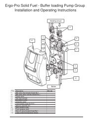
The 9kW unit has 1 inch BSPmale connections; these shouldbe connected to flexi hoses.To maintain flow rate werecommend 22mm pipework isused with this machine.All Pipework including the flexisneed to be insulated with 23mmlaggingIt is essential to connect anexpansion vessel, pressuregauge, pressure relief valve, fillingloop, magnetic filter/strainer <strong>and</strong>automatic bypass.A pump will be required, normallyin the flow. Dependant on systemresistance some times, 2 pumpsmay be required.Either a 3 port diverter valve or 2x 2 port valves need to beinstalled for domestic hot waterprioritisation.A flow meter / setter <strong>and</strong> flowswitch should be installed <strong>and</strong> astrainer in the return.The domestic hot water cylindermust be manufactured specificallyfor the heat pump.www.samsungehs.co.uk Hendra - January 2013 3
The 16 kW unit has 1 inch BSPmale connections, these shouldbe connected to flexi hoses(supplied).To maintain flow rate werecommend 28mm pipework isused with this machine.All Pipework including the flexisneed to be insulated with 23mmlaggingIt is essential to connect anexpansion vessel, pressuregauge, pressure relief valve, fillingloop, magnetic filter/strainer <strong>and</strong>automatic bypass.A pump will be required, normallyin the flow. Dependant on systemresistance some times, 2 pumpsmay be required.Either a 3 port diverter valve or 2x 2 port valves need to beinstalled for domestic hot waterprioritisation.A flow meter / setter <strong>and</strong> flowswitch should be installed <strong>and</strong> astrainer in the return.The domestic hot water cylindermust be manufactured specificallyfor the heat pump.www.samsungehs.co.uk Hendra - January 2013 4
Other components you need to supply <strong>and</strong> fit:An expansion vessel, pressure gauge, pressure relief valve <strong>and</strong> fillingloopMost heating engineers use a robokit with the appropriate size expansionvessel, this is sized exactly the same way as when using a boiler.<strong>Pump</strong>Your pump needs to supply 20l/min for the 9kW <strong>and</strong> 30l/min for the 16kW unit.The static resistance through the unit is 10kPa for the 9kW <strong>and</strong> 15kPa for the16kW unit. The flow meter has a resistance of around 5kPaThe cylinders (Gledhill) have a static resistance of 5kPa for the heat pump coil<strong>and</strong> 19kPa for the solar coil.The total resistance of the components will be approximately 39kPa for the size9 unit <strong>and</strong> if the cylinder is piped using both coils <strong>and</strong> approximately 44kPa forthe size 16 unit if using both coils.Flow switch <strong>and</strong> flow meterThe unit requires 16L / min flow at all times, if you don’t achieve thisE911 error will occur to check this flow switch is installed. The flowswitch comes with the control box.The flow Switch MUST be installed in horizontal pipe with at least150mm of straight pipe either side, connection is 1” female BSP. Thewire is 2m long <strong>and</strong> needs to connect into the wiring station. This wire can be extended tosuit. We recommend a flow meter is installed into the flow side of the flow switch as per thephoto. Adaptors may be required to enable this join. The flow switch is not IP65 rated(weatherproof) <strong>and</strong> so must not be installed externally.Diverter valvesIf you require domestic hot water <strong>and</strong> heating, diverter valves arerequired, you need to supply these. You can use a three port or 2port valves. The three ports must be of the diverter variety or wiredas a diverter, see wiring.Bypass ValveYou must install a bypass valve in the heating circuit as far away from the heatpump as possible. The bypass valve enables flow to be maintained as the tevsshut down at all times to prevent unit flow fault.Buffer vesselsWe don’t normally use buffer vessels on Samsung EHS systems; as long as the water volumecirculating is over 20 Litre. The inbuilt variable speed compressor means the unit can operatewithout a buffer.1m of 22mm pipe holds 380 ml of water, if you add the volume in the unit <strong>and</strong> components<strong>and</strong> make sure you put the bypass valve more than 25m from the heat pump your systemvolume will be adequate. When utilizing multiple units, a buffer or low loss header is requiredto hydraulically join the units.Magnetic FilterA magnetic filter with strainer must be installed in the return to the unit. A magnetic filterensures that debris/foreign materials do not cause restrictions within the pipework / system.GlycolA propylene glycol mixture must be utilized to prevent freezing of the water within the system.It is important that the glycol concentration is adequate to protect the unit in case of powerfailure in very cold conditions. If the unit freezes up there will be no warranty. Manufacturerdependant, a mix of around 25% should suffice.www.samsungehs.co.uk Hendra - January 2013 5
The CylinderThe cylinder needs to be installed less than 15m from the control box to allow for thetemperature sensor cable. Note the size <strong>and</strong> weight of the cylinder. Full installationinstructions are included with the cylinder.We only recommend using Gledhill heat pump stainless steel cylinders however othercylinders can be used IF the coil area is more than 2.5m^2. Smaller coils are not acceptable<strong>and</strong> cannot be used. Please do not attempt to utilize a st<strong>and</strong>ard central heating, non-heatpump optimized cylinder. Cylinders can be pressurised or open vented.When using Gledhill cylinders both the heat pump(top) coil <strong>and</strong> the solar (bottom) coil should beused. If no solar thermal is being used the heatpump should connect to both coils as per therecommendations in the Gledhill installationinstructions, <strong>and</strong> oversized by 30% to take intoaccount 0kW input from solar thermal in winter.G3The G3 regulations state in section 3.13a “for allindirect heat sources an overheat cut out todisconnect the supply to the stored vessel in theevent of the stored water overheating must beemployed so that the temperature of the storedwater does not exceed 100C”.For this reason the heat pump cylinder comes witha 2 port valve <strong>and</strong> tank stat. The valve can beinstalled in the flow as per the diagram.However as the refrigerant used in the SamsungEHS is R410A it is not able to physically heat above its critical temperature of 72.8C.Many heating engineers do not install this valve.If solar thermal is used it needs to be connected to the bottom coil of the cylinder as shown.www.samsungehs.co.uk Hendra - January 2013 6
www.samsungehs.co.uk Hendra - January 2013 7
www.samsungehs.co.uk Hendra - January 2013 8
Wiring <strong>and</strong> Power Supply InformationPowerThe EHS system needs 2 power supplies:One connects into the outdoor unit, 20 Amp for the 9kW <strong>and</strong> 32Amp for the size 16The one for the control box is 16 Amp <strong>and</strong> wires into the top ofthe breaker (mcb) in the boxImmersion <strong>Heat</strong>erThe immersion heater is connected into the control box terminalsA3 Neutral <strong>and</strong> A4 Live, The control box controls the operation ofthe immersion heater. If a fused spur is used it must be labelledas switching it off will cause an error.Communication cableThis must be run from the outdoor unit to the control box. Use 2 core flex 0.5-1mm (its 16Vac)SensorsThe blue cylinder sensor plugs into a socket T4 on thecontroller PCB <strong>and</strong> into the control sensor pocket in the tank inthe top ½ of the cylinder. The tanks sensor needs to go 115mminto the tank; it must be clipped so it can’t pull out.The red safety sensor is to avoid over temperature, when using a backup boiler or heater, itclips to the outlet of the boiler. If no backup boiler is used the sensor is not needed. It plugsinto a red socket T3 on the controller PCBThere is a black wire with a red plug in the box, this is not used.Sensors cannot not be cut or extended. Keep sensors away from mains cables pleaseDiverter ValvesUsing a three port valve3 way valve if A to heating & B to HW wire both the white <strong>and</strong> grey wires to B9, Blue to B7 therest are not used. If valve is piped the other way round use terminal B10 instead of B9Using two port valves2 port valve for Hot water, wire brown wire to B9 <strong>and</strong> Blue to B7, the rest are not used.2 port valve for heating zone 1 wire B14 live <strong>and</strong> B11 Neutral2 port valve for heating zone 2 wire B18 live <strong>and</strong> B17 NeutralThermostats/ timers <strong>and</strong> under floor heating manifoldsWe recommend in all cases the heating should be controlled by an external field suppliedroom stat / setback stat time clock etc. or run signal from a boiler enable signal from underfloor manifolds. If both rads <strong>and</strong> u floor are used in the same system the heat pump can becontrolled to run at 2 different set points one for each thermostat terminal.To run the unit with radiators make a connection from B20 – B24, to run the unit from underfloor heating make the connection from B20 - B22.B20 is permanently live 240V ac. B19 is NeutralWhen the stat is made the unit will run, when the stat opens the unit will stop. Hot waterproduction is not affected <strong>and</strong> will always take priority.<strong>Pump</strong>The circulation pump must be wired Live to B6 <strong>and</strong> neutral to B5, MAX pump power is 500Watts. If two pumps are used wire them both to these terminalswww.samsungehs.co.uk Hendra - January 2013 9
Start Up ProcedureDisable the cooling function, with the power OFF, removethe front of the remote controller, slide it upwards, turn itover <strong>and</strong> flick dip switch 1 to on.Cooling will no longer be availableOn the outdoor unit remove the front cover, thereare 2 screws at the top <strong>and</strong> one at the bottom, slidethe cover down. Inside the unit is a baseplateheater which is not normally required in the UK,disconnect the bottom wire white plug <strong>and</strong> tuck itout the wayFilling <strong>and</strong> flushing:The Building Regulations for Engl<strong>and</strong> <strong>and</strong> Wales, Part L, 2006, now require a central heatingsystem to be cleaned <strong>and</strong> inhibited chemically whenever the boiler is changed or any majorworks are carried out to the system.When installing any <strong>Heat</strong> pump we insist on a thorough system flush prior to connection of thenew equipment, your warranty will be at risk if a suitable flush is not carried out <strong>and</strong> thesystem becomes blocked during normal operation.Power flushingThe recommended procedure is to power flush the system in both forward <strong>and</strong> reversedirections at 110% of the normal flow rate <strong>and</strong> to use a chemical flushing agent whererequired.FillingUsing the power flusher fill the system with water <strong>and</strong> 25% Propylene Glycol to more than 1bar. It’s a good idea to note what the flow rate is through the system on the inline flow meter.DON’T fill the unit with a hose expecting no air locks, the heat pump is prone to air locking atthe outdoor unit, there is no auto air vent here.Don’t pour neat glycol into the unit; there is no chance of the heating pump moving neatglycol around the system.Powering UpApply power to indoor control box first then the outdoor unit.On the outdoor unit PCB the display will show 88 88, It will thensay Ad meaning it’s checking the addresses for you.Soon it will say Ad then flashing numbers 00, 01 02 etc. Finally itwill count up to 15. It has now finished addressing.It will now flash a message like 00 00, dE, F0 etc.This is it telling you the units it can see. The unit is now ready torun.If the outdoor unit / remote controller show E201 there is a commserror. Check the comms cable F1 <strong>and</strong> F2.In the middle of the control box PCB you will see two tiny leds onered <strong>and</strong> one orange flashing. The red one shows the signal leavingthe PCB <strong>and</strong> the orange shows the signal coming back from theoutdoor unit.www.samsungehs.co.uk Hendra - January 2013 10
Starting it up in heating modeIf you have two port valves you should find the heatingvalves are open <strong>and</strong> the hot water valve closed. If youhave a 3 port valve it should be open to heating mode.Start the unit my Pressing heating on off button (top leftinside the door) to start the unit, set the mode to heating(sun symbol)Set the desired water temperature i.e. 50C using the up<strong>and</strong> down buttons.Flow Switch <strong>and</strong> E911 READ THISWhen the pump is running a little house with a circle around it in the status window of thecontroller.The unit wants to see 14 l / min flow to activate the flow switch, if there is not enough flow aE911 fault will show every 15 secondsCheck:The flow rate on the flow meter it MUST be over 15l/minThe flow switch is connected to the PCB of the control boxThe flow switch is round the right way you can turn the head, there is an arrowAll valves are open.The pump speed is set at highestThere is no air in the systemThere is water in the systemIf none of this works you need a bigger pump or its air lockedTo clear the fault stop <strong>and</strong> start the machine again with the button on the remote controller.After 3 mins of pump operation the outdoor unit will start, don’t rush the system it takes timeCaution in Cold weatherIf the water in the system is below 10C the heat pump WILL NOTSTART.Press the blue view button you can see 4 sensor readings, press ituntil the pump symbol shows (a circle round a house). This is thewater temperature, if it’s below 10C the unit will not start but thepump will run.You must warm up the water to get the unit to run, the easiest wayto do this is to add a tank <strong>and</strong> use the immersion to warm up thetank first, the warm water from the tank will preheat the heat pump<strong>and</strong> it will start to operate. For more info see page 13.Set up the bypass valve with radiatorsIn heating mode check the unit is pushing water into the heating circuit only. Open the bypassvalve fully, if you are not sure set it to its lowest setting. Now close every radiator on thesystem except one.Using the flow meter check the flow rate is above 15/l to avoid E911 faults. Adjust the bypassvalve to achieve this. If 911 occurs clear the fault switching the unit on <strong>and</strong> off at the remote.The bypass is set now open the rads again.Set up the bypass valve with U floor heatingIn heating mode check the unit is pushing water into the heating circuit only. Open the bypassvalve fully, if you are not sure set it to its lowest setting. If 911 occurs clear the fault switchingthe unit on <strong>and</strong> off at the remote.Using the flow meter check the flow rate is above 15/l to avoid E911 faults. Adjust the bypassvalve to achieve this. If 911 occurs clear the fault by sending an off <strong>and</strong> then an on comm<strong>and</strong>to the unit. Reset the power to the ufloor manifold to do this.The bypass is set now turn up the wall stats again.www.samsungehs.co.uk Hendra - January 2013 11
What the symbols mean:Setting the correct timewww.samsungehs.co.uk Hendra - January 2013 12
Telling the unit it has a tank.When the unit is delivered it doesn’t think there is ahot water cylinder tank installed. You have to tellthe unit about the cylinder.Press test button for 3 secondsThe screen will start to flash,Press up twice, 30 will appearPress set (grey) 3011 will appear Press set (grey),0 will appear Press up once 1 will appearPress set (grey) once 3011 will appear presscancel delete 2 x to return to normal screenIF E904 error shows the tank sensor is notconnectedStarting the System in hot water modePress Hot water on off button to start theunit, top left button.The unit speed is adjusted with the std, ecopower button, set to middle position, 2 dotsshowing.Set the desired temperature 48C using theup <strong>and</strong> down buttons. This can ONLY be setif the <strong>Heat</strong>ing function is switched OFF <strong>and</strong>HW is onNOTE when the unit is heating the tank thiscoke can symbol shows on the controller.After 20 mins of operation if the tank temperature is not reached the immersion heater willstart to help out. This time can be adjusted using setting 3032Press the blue view button you can see 4 sensorreadings, press it until the tap symbol shows.This is the tank temperature. It will display for about10 seconds. Check the temperature is not fluctuatingmore than 1C in this time. If it is the sensor is notinstalled correctly or is damaged. If this happens thesystem WILL NOT WORK PROPERLEYwww.samsungehs.co.uk Hendra - January 2013 13
Run test in hot water modeIn hot water mode check that the 3 port valve or the 2 x 2 ports are sending water into the hotwater cylinder, if not check the wiring.Using the check button (blue) on the remote controller check the hot water cylindertemperature <strong>and</strong> note it down, the hot water temperature is displayed when the tap symbolshows.After 15 minutes of running check the hot water temperature again, it should have risen, againnote the temperature.If the temperature has not raised check the temperature sensors is installed properly <strong>and</strong>again check the operation of the 3 port or 2 port valves. If the unit is running well it shouldheat the cylinder to 48C without needing the immersion heaterSetting up the tank immersion heaterThe Gledhill tank has an immersion heater with its own stat; thisMUST be set to 70C. This is to avoid the immersion heater cuttingout before the legionella function is completeTank timerTo avoid the tank heating being switched off we always add 2 ontimers a day one at 3-00 am <strong>and</strong> one at 15-00 pm.Press daily button once, no 1 <strong>and</strong> on shows, press set (grey), press up or down until the tapsymbol shows at the top of the screen with2 dots press set, adjust hours with up ordown button to 3 am press set, minutesflash press set. Now everything flashespress set (grey). No 2 appears do thesame again but for 15-00.After everything is set no 3 will show.Press cancel delete twice, the normalscreen will show. Daily will appear next tothe time. The timer is activeTo delete the timers press daily 2 x the setschedule will show, press <strong>and</strong> hold canceldelete for 5 seconds, keep doing this untilno1 shows, press cancel delete 2 x <strong>and</strong> inthe normal screen daily will havedisappeared.The hot water tank has priority over the heating, if the tank temperature falls 5 degrees belowits set point the unit will automatically switch to heating the cylinder. Once set temperature isachieved the unit will go back to heating the house.The hot water cylinder loses almost no heat (1/3 a degree an hour) if no hot water is used.The hot water cylinder takes less than an hour to heat up from cold. If you need hot watervery fast the DHW button forces the unit to heat the water flat out, the unit will stay in thismode until you press the DHW button againTo protect from legionella the tank is heated to 60 degrees C once a week automatically.Performance testingWith the unit running flat out measure the temperature of the air temperature as it enters thecoil <strong>and</strong> the ambient temperature well away from the unit? They need to be the same for theunit to operate properly.Not enough hot water.The Water storage temperature is lower (48C) than a normal fossil fuel cylinder. It’s importantto check that any shower or bath mixers do not further reduce the water temperature. Usingyour thermometer check that the hot water comes out the tap at the same temperature itleaves the cylinder. If it doesn’t you might need to make adjustments to taps mixers etc.DON’T raise the tank temperature to compensate.www.samsungehs.co.uk Hendra - January 2013 14
Field SettingsMany field settings will need to be made: NOTE the set button is the grey one not the blueWhen finished or if you get lost press cancel delete 2 x to return to the normal screenNote: if you set a field setting <strong>and</strong> go back to check it, it will not have changed, the fieldsetting do not get written to the PCB until you finish setting <strong>and</strong> exit.Field settings to set see user manual for a full list1061 30s length of time backlight is on in the Samsung rc2011 -2 low ambient setting for optimisation set to -5 in Scotl<strong>and</strong>2012 +15 high ambient temp for optimisation2021 45C for u floor. Hi water temp for optimisation2022 37C lowest water temp for optimisation2031 50C for rads. Hi water temp for optimisation2032 35C lowest water temp for optimisation2091 1 tells unit to use a u floor run signal2092 1 tells unit to use an external room stat3011 1 tells unit it has a tank connected3025 50 mins, max tank heating time, make longer for big tanks i.e. 75 mins for 300L3032 30 mins, delay time before immersion heater starts in tank mode3042 Tuesday day legionella happens (always use Tuesday)3043 3 am time it happens3044 60 C legionella temp3061 1 if a solar thermal system is installedA full list of field settings are in the installation <strong>and</strong> user manual which come with the outdoorunitwww.samsungehs.co.uk Hendra - January 2013 15
Operating the System in heating mode using an externalthermostat <strong>and</strong> / or a boiler run signal from an under floormanifold.You have now set the unit up to run from an external signal; the controller no longer drives theunit.Using a field supplied room thermostat or signal from an under floor heating system. This iswired to the thermostat terminals for radiators wire from B20 – B24, for under floor heatingwire to B20 - B22When the contact is made the unit will start <strong>and</strong> the water temperature will be controlled bythe boiler, you will not have any control over it. The water temperature is determined by theoutdoor temperature; the colder it is outside the warmer the water.You will see 0.0C on the screen; this shows the unit under external control using weathercompensation function to work out the water temperature. You set this up in the field settings2011 to 2031. If you need to boost the heating water temp this can be done by pressing thesilver up <strong>and</strong> down buttons. This boosts the radiators by up to +5 C but warning this will costmore money to run.The heat pump is operated using a signal from a room stat (field supply) or from the underfloor heating manifold only. When you make a run signal a sun will appear in the screen of theRC, the pump will also start.When an external stat or run signal is used most of the functions of the Samsung remote aredisabled.A waging finger shows at the bottom to show this.All these buttons are disabled <strong>and</strong> the functions they control are also disabledNote: when the heating comm<strong>and</strong> is sent to the unit it will not start for 3 minutes. Andwhen the thermostat or signal is removed the pump will run on for up to 6 minutes.www.samsungehs.co.uk Hendra - January 2013 16
<strong>Maintenance</strong> Monobloc systemsThe Samsung heat pump should be maintained at least once a yea r to comply with warranty<strong>and</strong> RHI.<strong>Maintenance</strong> procedureStop the unit, clean the strainer or magnetic filter in accordance with manufacturer’srecommendations <strong>and</strong> replace it.Test the concentration of the Anti-freeze (glycol) in the system using a Glycol tester the levelshould be 25%. If you don’t have a glycol tester a Samsung glycol tester can be bought fromyour heat pump supplier or online.Refill the unit, pressure should be 1 -2 bar,We need to test the operation of the unit against the hot water cylinder. So first we need todraw off 20 liters of water, run a couple of taps for 5 mins to achieve this.Test the unit as described on page 13 <strong>and</strong> 14The unit should start up automatically in hot water mode, if it doesn’t press the top right buttonon the controller, in 3-4 mins it will start heating the tank, a coke can symbol will show in thestatus section of the remote controller.The heat pump should be able to achieve 48C cylinder temperature without using theimmersion heater.While running, check the coil on the heat pump for damage & debris, the coil needs washingwe recommend you use Pro-universal heat pump cleaner, this is available online or from yourheat pump supplier, one bottle will do up to 3 units. Instructions are given on the bottle.Hot water Cylinder:Check electrical connections & sensor are fixed properly <strong>and</strong>the overheat thermostat is set to 70C.Overheat Thermostat AdjustmentPress the silver immersion button on the Samsung remote controller; this will force theimmersion heater on. Check immersion heater works properly, Measure the current drawn bythe heater; it should be 12-13 Amps.Measure the temperature of the flow using the remote controller.Measure the flow rate from the flow meter.With the unit running flat out measure the temperature of the air as it enters the coil <strong>and</strong> thetemperature of the air in the garden. They should be the same check cold air is notrecirculating.www.samsungehs.co.uk Hendra - January 2013 17
Leave this with the HomeownerYour Samsung heat pump heats the house <strong>and</strong> hot water cylinder much like a normalfossil fuel boiler however there are a couple of differences which you should notice.1 The radiator temperatures are lower than normal <strong>and</strong> will alter as the outdoortemperature changes. The colder it is outside the warmer the rads <strong>and</strong> vice versa.This function is automatic <strong>and</strong> is designed to save you money. At hottest they willreach 50C. If you would like a constant radiator temperature this can be set by anengineer but it will increase your run costs by up to 25%.2 The system is designed to run continuously in cold weather, turning the system on<strong>and</strong> off will make the house uncomfortable <strong>and</strong> will increase your run costs. The mostefficient way to run this heating system is to leave it running at the set temperature 24hours a day in winter time. If you turn off the heating <strong>and</strong> let the house get cold (lessthan 17C) it will take a very long time to warm back up to a sensible temperature.Your systems have been set up to be simple to operate.The Samsung controller looks like this, you should not usethis or press the buttons on it, it is for commissioning <strong>and</strong>making settings to the system only.You should see 0.0C on the screen this means the unit isunder external control from a room thermostat.If the system goes in to fault, the screen will show a numberat the bottom starting with E, for example E911 – A00The engineer will want to know this number when you callhim.<strong>Heat</strong>ingControl of the heating is by your wall mounted thermostat, not the Samsung controller; youneed to read the instructions for this thermostat as its field supplied. The boiler will run whentold too by the thermostat. DON’T set the room temperature too low, the heat pump takestime to recover the house temperature, as a rule don’t set the temperature more than 2degrees below your normal set temperature when you go out of the house or it will take a longtime to recover.To switch off the heating in summer set the temperature down to 16C to avoid the heatingstarting up.To control the temperature in your rooms please use the radiator valves.Hot waterYour system will keep the hot water cylinder hot at all times automatically, as you use thewater the heat pump will constantly top up the cylinder. A cold cylinder should be reheatedwithin an hour. An anti legionella operation will be completed at a predetermined time everyTuesday morning.Warranty ImportantAttached to this document is a warranty page your installer must fill in both sides <strong>and</strong> return itto activate the warranty. No claim will be processed without this paperwork being returned.www.samsungehs.co.uk Hendra - January 2013 18
Samsung EHS WarrantyUnit 2 Warrior ParkEagle CloseCh<strong>and</strong>lers FordSO534NFWeb site www.samsungehs.co.ukEmail sales@samsungehs.co.ukWarranty Registration CardPlease complete both sides of this warrantycard <strong>and</strong> return it to activate the warrantyInstaller Name <strong>and</strong> Addresstelephone number & contact name<strong>Installation</strong> AddressWhere was the unit purchased:Date Installed<strong>Heat</strong> <strong>Pump</strong> Model NoHot water CylinderinstalledYes/noDate ofcommissioningSerial NoCylinder make<strong>and</strong> model noWarranty period St<strong>and</strong>ard 3 years OptionalextendedwarrantyExtended 7 yearsPlease sign below <strong>and</strong> return to our Warranty Dept. via fax 08458430122, emailsales@samsungehs.co.uk or post to the address above. Once received <strong>and</strong> ifaccepted we will then arrange for the replacement component(s) to be despatched.SignatureDatewww.samsungehs.co.uk Hendra - January 2013 19
Samsung EHS WarrantyUnit 2 Warrior ParkEagle CloseCh<strong>and</strong>lers FordSO534NFWeb site www.samsungehs.co.ukEmail sales@samsungehs.co.ukWarranty Registration CardPlease complete both sides of this warrantycard <strong>and</strong> return it to activate the warrantyFor terms <strong>and</strong> conditions of the warranty please refer to the warranty document atwww.samsungehs.co.uk / information / downloads / technical downloads.www.samsungehs.co.uk Hendra - January 2013 20