SmartLVL 15 Design Guide - Tilling Timber
SmartLVL 15 Design Guide - Tilling Timber
SmartLVL 15 Design Guide - Tilling Timber

You also want an ePaper? Increase the reach of your titles
YUMPU automatically turns print PDFs into web optimized ePapers that Google loves.
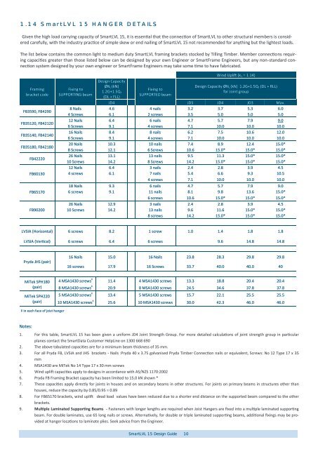
1.14 <strong>SmartLVL</strong> <strong>15</strong> HANGER DETAILSGiven the high load carrying capacity of <strong>SmartLVL</strong> <strong>15</strong>, it is essential that the connection of <strong>SmartLVL</strong> to other structural members is consideredcarefully, with the industry practice of simple skew or end nailing of <strong>SmartLVL</strong> <strong>15</strong> not recommended for anything but the lightest loads.The list below contains the common light to medium duty <strong>SmartLVL</strong> framing brackets stocked by <strong>Tilling</strong> <strong>Timber</strong>. Member connections requiringcapacities greater than those listed below can be designed by your own Engineer or SmartFrame Engineers, but any non-standard connectionsystem designed by your own engineer or SmartFrame Engineers may take some time to have fabricated.Framingbracket codeFB3590, FB4290FB35120, FB42120FB35140, FB42140FB35180, FB42180FB42220FB60130Fixing toSUPPORTING beam<strong>Design</strong> CapacityØN j (kN)1.2G+1.5Q f(DL + FLL)Fixing toSUPPORTED beamWind Uplift (k 1 = 1.14)<strong>Design</strong> Capacity ØN j (kN) 1.2G+1.5Q f (DL + RLL)for Joint groupJD4 JD5 JD4 JD3 Max.8 Nails 4.6 4 nails 3.2 3.7 5.3 6.04 Screws 6.1 2 screws 3.5 5.0 5.0 5.012 Nails 6.4 6 nails 4.7 5.7 7.9 9.06 Screws 9.1 4 screws 7.1 10.0 10.0 10.016 Nails 8.4 8 nails 6.2 7.5 10.6 12.06 Screws 9.1 4 screws 7.1 10.0 10.0 10.020 Nails 10.3 10 nails 7.4 8.9 12.4 <strong>15</strong>.0*8 Screws 12.1 6 Screws 10.6 <strong>15</strong>.0* <strong>15</strong>.0* <strong>15</strong>.0*26 Nails 13.1 13 nails 9.5 11.3 <strong>15</strong>.0* <strong>15</strong>.0*10 Screws 14.2 8 Screws 14.2 <strong>15</strong>.0* <strong>15</strong>.0* <strong>15</strong>.0*12 Nails 6.4 3 nails 2.4 2.8 3.9 4.54 screws 6.1 7 nails 5.4 6.6 9.3 10.54 screws 7.1 10.0 10.0 10.018 Nails 9.3 6 nails 4.7 5.7 7.9 9.0FB651706 screws 9.1 11 nails 8.1 9.8 13.6 <strong>15</strong>.0*6 screws 10.6 <strong>15</strong>.0* <strong>15</strong>.0* <strong>15</strong>.0*26 Nails 12.9 3 nails 2.4 2.8 3.9 4.5FB90200 10 Screws 14.2 13 nails 9.6 11.6 <strong>15</strong>.0* <strong>15</strong>.0*8 screws 14.2 <strong>15</strong>.0* <strong>15</strong>.0* <strong>15</strong>.0*LVSIA (Horizontal) 6 screws 8.2 1 screw 1.0 1.4 1.8 1.8LVSIA (Vertical) 6 screws 6.4 6 screws 9.6 14.8 14.8Pryda JHS (pair)16 Nails <strong>15</strong>.0 16 Nails 23.8 28.3 29.8 29.816 screws 17.9 16 Screws 33.7 40.0 40.0 40MiTek SPH180(pair)MiTek SPH220(pair)4 MSA1430 screws ‡ 11.4 4 MSA1430 screws 13.3 18.8 20.4 20.48 MSA1430 screws ‡ 20.9 8 MSA1430 screws 24.5 34.6 37.8 37.85 MSA1430 screws ‡ 13.4 5 MSA1430 screws <strong>15</strong>.7 22.1 25.5 25.510 MSA1430 screws ‡ 25.6 10 MSA1430 screws 30.0 42.3 46.0 46.0‡ in each face of joist hangerNotes:1. For this table, <strong>SmartLVL</strong> <strong>15</strong> has been given a uniform JD4 Joint Strength Group. For more detailed calculations of joint strength group in particularplanes contact the SmartData Customer HelpLine on 1300 668 6902. The above tabulated capacities are for a minimum beam thickness of 35 mm.3. For all Pryda FB, LVSIA and JHS brackets - Nails :Pryda 40 x 3.75 galvanised Pryda <strong>Timber</strong> Connection nails or equivalent, Screws: No 12 Type 17 x 35mm4. MSA1430 are MiTek No 14 Type 17 x 30 mm screws5. Wind uplift capacities apply to designs in accordance with AS/NZS 1170:20026. Pryda FB Framing Bracket capacity has been limited to <strong>15</strong>.0 kN shown *7. These capacities apply directly for joints in houses and on secondary beams in other structures. For joints on primary beams in structures other thanhouses, reduce the capacity by 0.85/0.95 = 0.898. For FB65170 brackets, wind uplift dead load values have been reduced due to a shorter end distance on the supported beam compared to the otherbrackets.9. Multiple Laminated Supporting Beams - Fasteners with longer lengths are required when Joist Hangers are fixed into a multiple laminated supportingbeam. For double laminates, use 65 long nails or screws. Alternatively, for double or triple laminated supporting beams, additional fixings may be providedat hanger locations to laminate plies. Seek advice from the Engineer.<strong>SmartLVL</strong> <strong>15</strong> <strong>Design</strong> <strong>Guide</strong> 10