DOORS Page 1 of 10 TECHNICAL SPECIFICATION â SECTION 8 ...
DOORS Page 1 of 10 TECHNICAL SPECIFICATION â SECTION 8 ...
DOORS Page 1 of 10 TECHNICAL SPECIFICATION â SECTION 8 ...

Create successful ePaper yourself
Turn your PDF publications into a flip-book with our unique Google optimized e-Paper software.
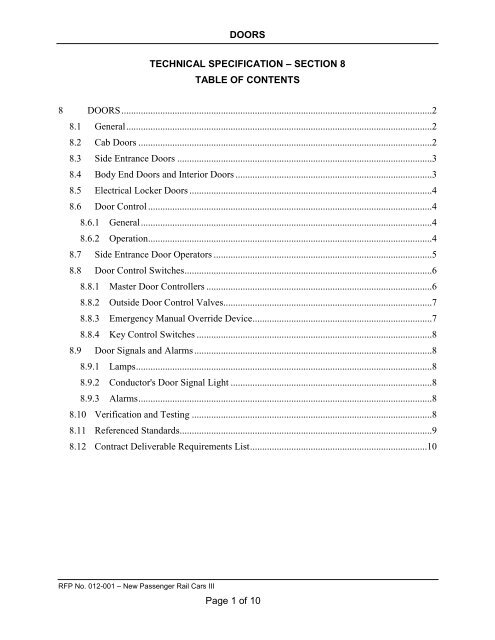
<strong>DOORS</strong><strong>TECHNICAL</strong> <strong>SPECIFICATION</strong> – <strong>SECTION</strong> 8TABLE OF CONTENTS8 <strong>DOORS</strong> ................................................................................................................................28.1 General ..............................................................................................................................28.2 Cab Doors .........................................................................................................................28.3 Side Entrance Doors .........................................................................................................38.4 Body End Doors and Interior Doors .................................................................................38.5 Electrical Locker Doors ....................................................................................................48.6 Door Control .....................................................................................................................48.6.1 General ........................................................................................................................48.6.2 Operation.....................................................................................................................48.7 Side Entrance Door Operators ..........................................................................................58.8 Door Control Switches ......................................................................................................68.8.1 Master Door Controllers .............................................................................................68.8.2 Outside Door Control Valves......................................................................................78.8.3 Emergency Manual Override Device..........................................................................78.8.4 Key Control Switches .................................................................................................88.9 Door Signals and Alarms ..................................................................................................88.9.1 Lamps ..........................................................................................................................88.9.2 Conductor's Door Signal Light ...................................................................................88.9.3 Alarms .........................................................................................................................88.<strong>10</strong> Verification and Testing ...................................................................................................88.11 Referenced Standards........................................................................................................98.12 Contract Deliverable Requirements List .........................................................................<strong>10</strong>RFP No. 012-001 – New Passenger Rail Cars III<strong>Page</strong> 1 <strong>of</strong> <strong>10</strong>
<strong>DOORS</strong>8 <strong>DOORS</strong>8.1 Generala. The carbody on all cars shall be provided with:1) Two (2) or Four (4) side entrance doors that allow passengers access to the passengercompartment.2) Two (2) body end doors that isolate the passenger compartment from the end passthroughat each end <strong>of</strong> the car.3) Cab cars shall have one (1) lockable door separating the cab compartment from thepassengers.4) Cab cars shall have one (1) each side an exterior crew switch for opening and closing <strong>of</strong>the side loading doors. Design and operation shall be approved by VRE.b. Door design, construction and operation shall meet all requirements <strong>of</strong> APTA RP-C&S-012-02 and APTA SS-M-18-<strong>10</strong>.c. All doors and doorways shall comply with all applicable sections <strong>of</strong> 49CFR Parts 27, 37 and38, latest version, for ADA compliance.d. Doors shall be vibration free and well insulated against temperature and sound transmission.e. Any exterior doors shall have adequate weather stripping for operation at 90 mph (145 kmph)f. Doors shall be constructed <strong>of</strong> ample gauge material, to provide proper strength and rigidity tosustain a concentrated load <strong>of</strong> 200 lb-force (0.89 kN) applied perpendicularly on an area 24-in. x 12-in. (6<strong>10</strong> mm x 305 mm) to the surface <strong>of</strong> the doors at the center <strong>of</strong> the front edgewith the long axis parallel to that <strong>of</strong> the door, with a maximum deflection <strong>of</strong> 0.25-in. (6.4mm) without a set while the door is supported at both ends.g. Joints and edges shall be thoroughly sealed against moisture. Drain holes shall be located inthe bottom <strong>of</strong> the doors to allow the escape <strong>of</strong> condensed moisture.h. Steel tapping plates shall be provided for the attachment <strong>of</strong> all door hardware, operatingarms, etc.i. Doors and door hangers shall be readily adjustable and accessible to allow raising orlowering doors.j. The door design configuration for all door types on all car types shall be submitted to VREfor review and acceptance. [CDRL 8-01]8.2 Cab Doors1) The door shall be designed so that the emergency egress for the passengers is unaffectedwhen the door is closed and locked.2) For security purposes, all engineer’s cab door shall have item number 14D914 (Chrome)and item number 15D214C from Peephole Logistic Supplies, or approved equal. Thepeephole shall be mounted in the center <strong>of</strong> the door horizontally and at an easilyaccessible height when seated in the engineer’s seat.RFP No. 012-001 – New Passenger Rail Cars III<strong>Page</strong> 2 <strong>of</strong> <strong>10</strong>
<strong>DOORS</strong>3) The door shall also be <strong>of</strong> “bullet-pro<strong>of</strong>” construction and is to be approved by VRE priorto construction.8.3 Side Entrance Doorsa. The side entrance doors shall be designed to maximize the number <strong>of</strong> passengers entering ordisembarking the train.b. Side entrance doors shall be located on the lower level <strong>of</strong> the vehicle. Boarding to a mid orupper level shall not be acceptable.c. The doors shall be mounted, as close to the outside line <strong>of</strong> the car as construction permits.d. The doors shall be <strong>of</strong> stainless steel hollow or aluminum honeycomb construction withstainless steel skins, and be properly sealed against moisture.e. The side entrance doors will have a window or windows and they shall be at convenientheight to provide easy vision when standing.f. The side doors shall be arranged for either electric or pneumatic operation as defined inSection 8.56.g. The doors shall be adequately weather stripped for the intended services, and shall havecushioning rubber (on the door edge and door post) to prevent personal injury.h. The door pockets shall have drain pans with bottom sloping towards under car drains.i. The door pockets shall be heated to prevent freezing by an automatic, electric resistance,protective heater or other device acceptable to VRE. [CDRL 8-02] The heater shall beaccessible for replacement at each pocket and have electrical connectors for ease <strong>of</strong>replacement.j. The Contractor shall make recommendations, based on his experience to preclude moisture,ice and snow build-up in the door pocket and provide suitable equipment acceptable to VRE.[CDRL 8-03]k. If one set <strong>of</strong> side entrance doors per side are proposed, each side entry door shall provide aminimum clear open width <strong>of</strong> 72-in. If two sets <strong>of</strong> side entrance doors per side are proposed,each entry shall provide a minimum clear open width <strong>of</strong> 48-in.8.4 Body End Doors and Interior Doorsa. Doors will be designed to meet 49CFR238.235 and APTA SS-C&S-012-02 standards for caband coach cars.b. The door will have a single glass window that is at a convenient height to provide easy visionwhen standing.c. The body end doors shall have locks that can be accessed from both the inside and outside <strong>of</strong>the car and use a VRE standard coach key to lock and unlock them. The keyways shall beequipped with spring loaded covers to prevent intrusion <strong>of</strong> foreign materials and debris.d. The doors shall be adequately weather stripped for the intended services, and shall havecushioning rubber (on the door edge and door post) to prevent personal injury.e. The door pockets shall have drain pans with bottom sloping towards under car drains.RFP No. 012-001 – New Passenger Rail Cars III<strong>Page</strong> 3 <strong>of</strong> <strong>10</strong>
<strong>DOORS</strong>f. Doors, except cab-end, body end doors, will be powered by either a pneumatic or electricoperator. There shall be a three position switch located adjacent to the door that allows thedoor to work in either automatic mode, manual mode, or locks the door in the closedposition. The switch can only be activated by use <strong>of</strong> a VRE coach key. There shall be twomethods to activate the door mechanism, one is a push plate located at a convenient heightadjacent to the door and the other is a kick plate located at the base <strong>of</strong> the door. The doortiming shall be adjustable from 15 seconds to 30 seconds and include obstruction detection.8.5 Electrical Locker Doorsa. All electrical locker doors shall be accessible by a standard coach car key.8.6 Door Control8.6.1 Generala. The side entrance doors on the cars shall be arranged to operate from local Master DoorControllers (MDC) located one on each side <strong>of</strong> the car. If there are two side entrance doorson each side <strong>of</strong> the train, the MDCs shall be located diagonally across from each other.1) These controllers shall use the low voltage AC train line signals to control either electric orpneumatic door operators.2) Each door shall also have venting air valves for manual use and/or emergency override.3) Operation <strong>of</strong> the side entrance doors must be completely compatible with those on otherVRE cars.b. Design <strong>of</strong> the side door control system shall meet the requirements <strong>of</strong> 49CFR238 and the -recommendations <strong>of</strong> APTA RP-C&S-012-02 and APTA SS-M-18-<strong>10</strong> (latest versions).c. All cars shall be tested for multiple unit operation <strong>of</strong> door control prior to shipment.d. The final design <strong>of</strong> the side entrance door control, door operator, and door indication systemsshall be submitted to VRE for review and acceptance, before the equipment is installed on thefirst car. [CDRL 8-04] Complete details <strong>of</strong> the design, showing compliance with allrequirements <strong>of</strong> this Section and other relevant sections <strong>of</strong> the contract, shall be provided. Thedesign review shall include drawings and schematics, and also a written technical description <strong>of</strong>operation <strong>of</strong> the circuit. The description shall include sufficient information as to allow thereader to understand operation <strong>of</strong> all push-buttons, lights and annunciation signals. The designshall be submitted within 120 days <strong>of</strong> Notice to Proceed (NTP).8.6.2 Operationa. The side entrance doors shall be arranged for remote electric control and pneumatic or electricoperation.b. The side entrance door control system shall be train lined to permit operation <strong>of</strong> all sideentrance doors on one side <strong>of</strong> the train from any vestibule Master Door Controller panel onthe same side <strong>of</strong> the train.c. Side entrance Master Door Controller (MDC) panels shall be provided on each side <strong>of</strong> thetrain so that an attendant can operate the buttons to open and close the doors while standing inRFP No. 012-001 – New Passenger Rail Cars III<strong>Page</strong> 4 <strong>of</strong> <strong>10</strong>
<strong>DOORS</strong>the doorway. If the design calls for two side entrance doors per side, the MDCs shall belocated on doors diagonal from each other.d. One train line circuit shall be utilized to open side entrance doors for each side <strong>of</strong> the train.1) Side entrance doors shall be closed by utilizing one other train line circuit for each side <strong>of</strong>the train. (See Section 7 for trainline assignments).2) The side entrance door control circuits shall be designed to preclude operation as a result <strong>of</strong>electrical transients on the control train lines.e. The door control system may consist <strong>of</strong> traditional relay logic, electronic or microprocessorcontrol.f. All door control circuits for one (1) side <strong>of</strong> the car shall be separate and distinct from thosefor the other side <strong>of</strong> the car. There shall be no shared components unless specifically calledfor herein. Other door control arrangements, based on the Carbuilder's past practice, shall beconsidered.g. No operational failure <strong>of</strong> a microprocessor, its output stage, relay or other component in thedoor control system shall result in an unsafe condition in which doors may open withoutcommand or falsely indicate a closed and locked condition. In the event <strong>of</strong> microprocessorfailure, all associated door warning status lights shall become illuminated.h. Door control logic and circuitry shall be arranged so as to permit train operation with sidedoors open only if the car is equipped with a center vestibule.1) If the side entrance door/doors open directly into the passenger compartment the trainshall not be able to leave the station unit the door/doors are closed.2) It shall be possible for a crew member to actuate the "Local Open" control on theadjacent control panel, in which case the side door will open.i. Traction interlock with door controls is required. The manufacturer shall submit a design toVRE for approval. CDRL [8-05]j. Doors shall not open unless at zero speed, except a “This Door Only” or “Local” button shallfunction at all speeds when the MDC is keyed up. All doors shall close automatically whentrain motion is detected, except a door which has been opened by the “This Door Only” or“Local” button shall remain open if the MDC remains keyed on.8.7 Side Entrance Door Operatorsa. Each side entrance door shall be actuated by an electric or pneumatic operator, which shall bemounted above the side door opening or in close proximity to the side door, located so as to bereadily accessible for maintenance and well protected from wind driven precipitation.b. An access panel shall be provided for the door operator.c. It shall not be necessary to dismantle any equipment to gain access to the door operator.d. The door operator and/or the operating linkage shall be designed so that sufficient dampeningaction will be provided to keep the door from bouncing <strong>of</strong>f its stops at the end <strong>of</strong> either theopening or closing cycle; and, so that the speed <strong>of</strong> the doors from the moment <strong>of</strong> energizing thedoor operator to the completion <strong>of</strong> operation including cushioning, shall be as follows:RFP No. 012-001 – New Passenger Rail Cars III<strong>Page</strong> 5 <strong>of</strong> <strong>10</strong>
<strong>DOORS</strong>1) Opening: 3.5 seconds ± 0.52) Closing: Nominal 4.5 seconds for door leaf (<strong>10</strong>.0 ± 0.5 seconds with annunciation)3) Adjustable 2.5 to 5.0 seconds leaf actual closinge. The door operator, control circuitry, and operating linkage for each leaf shall be such that theforce available during the closing cycle shall be not greater than 36 lbs. force (160N)measured at any point along the stroke.f. The door operator mechanism shall be setup so that, in the event <strong>of</strong> a passenger or iteminterfering with the door closing, the obstruction will cause the door panel to be stopped.g. All sliding side doors shall be adjusted to have a maximum pull <strong>of</strong> 8 lbs. force (36N) with thedoor operators disconnected.h. All left hand door operators shall be interchangeable with each other, while all right handdoor operators shall be interchangeable with each other, and shall be replaceable withouthaving to remove other apparatus.i. Devices used in the door operator for position sensing shall be revenue service-proven solidstatesensors or industry standard proven limit switches, unless otherwise approved by VRE.[CDRL 8-06]j. Indication circuit contacts or limit switches shall be arranged to directly or indirectly verifythe locking <strong>of</strong> the door leaf.k. Components used in controlling door operators or control trainlines shall not be mounted onthe door operator.l. Door controls will include an adjustable door open and door close cushion on the end <strong>of</strong> eachopen and closing cycle to prevent doors slamming against the door header or opening stops.8.8 Door Control SwitchesThe location and details <strong>of</strong> all switches and switch panels shall be submitted for review andacceptance by VRE. [CDRL 8-07]8.8.1 Master Door Controllersa. A Master Door Controller (MDC) panel shall be provided on each side <strong>of</strong> the train, located sothat an attendant can operate the buttons to open and close the doors while standing in thedoorway.b. The door control shall be arranged so that the doors on a train side shall be controllable onlyfrom MDCs on that side <strong>of</strong> the train.c. The panel shall be fitted with six (6) momentary push buttons, arranged in three (3) verticalcolumns <strong>of</strong> two (2) push buttons each.1) One (1) pair <strong>of</strong> push buttons shall open and close the side entrance doors in the section <strong>of</strong>the train forward <strong>of</strong> the active control position.2) One (1) pair <strong>of</strong> push buttons shall open and close the side entrance doors in the section <strong>of</strong>the train rearward <strong>of</strong> the active control position.3) The third (center) pair <strong>of</strong> push buttons shall open and close the door at that position only.RFP No. 012-001 – New Passenger Rail Cars III<strong>Page</strong> 6 <strong>of</strong> <strong>10</strong>
<strong>DOORS</strong>d. The section <strong>of</strong> the train that each pair <strong>of</strong> push buttons controls shall be suggested by thelocations <strong>of</strong> the push buttons, and the sections indicated by the words "Left", “Local”, and"Right".e. In each pair <strong>of</strong> push buttons, the bottom button shall be colored black and shall close the doorswhile the top button shall be colored black and shall open the doors.f. The panel shall require the insertion <strong>of</strong> the VRE coach key to make any buttons operative.g. It shall be possible to remove the door key after the doors have been opened, and have the doorsremain open; and to insert the door key and close the doors from a different MDC than that fromwhich they were opened, on the same side only.h. Door control switches shall be <strong>of</strong> the momentary contact type and circuitry shall be arranged sothat once the button is pressed the operation cycle shall be completed even if button isimmediately released.i. Door control panels shall have an unpainted polished stainless steel or aluminum bright metalfinish.8.8.2 Outside Door Control ValvesExternal access shall be by means <strong>of</strong> bleed valves (ball type), which are adjacent to one door leaf oneach side <strong>of</strong> the car. The bleed valves shall deplete the door operating mechanism air supply topermit manual opening <strong>of</strong> both leafs, and when closed shall allow the door operating air reservoir torecharge to reactivate the door air operating mechanisms.Instructions for opening doors in an emergency shall be provided adjacent to the valves.Instructions shall be printed on white retro-reflective material.8.8.3 Emergency Manual Override Devicea. The emergency manual override design shall meet the requirements <strong>of</strong> 49 CFR 238.235 and therecommendations <strong>of</strong> APTA RP-C&S-012-02 and APTA SS-M-18-<strong>10</strong>.b. All side door operators shall be so arranged so that they may be manually opened for anemergency exit from inside and from outside <strong>of</strong> the car at each door location.c. Devices shall be located immediately adjacent to the door they control.d. The manual override device shall be readily accessible without the use <strong>of</strong> tools or otherimplements and shielded with a sliding stainless steel cover.e. The manual override device shall require manual resetting.f. The manual override device shall signal the traction interlock circuit so that when the device isactivated the train shall not be allowed to move.g. The emergency release mechanism shall be capable <strong>of</strong> unlocking and releasing the door so thedoor can be manually opened without electric or pneumatic supply.h. The interior release handle or lever shall be accessible to a person standing at the door andinstalled in a location acceptable to VRE. [CDRL 8-08] The override device design andlocation shall take into consideration 49CFR38 and MIL-STD-1472E.i. The force necessary to actuate the interior mechanism shall not exceed 20 lbs.RFP No. 012-001 – New Passenger Rail Cars III<strong>Page</strong> 7 <strong>of</strong> <strong>10</strong>
<strong>DOORS</strong>j. Signs as accepted by the VRE and conforming to APTA SS-PS-002-098 Rev 3, shall be placedon the inside <strong>of</strong> each side door identifying the location <strong>of</strong> the manual release handle and givesimplified instruction. [CDRL 8-09]1) The exterior release device shall be an air valve with appropriate signage.k. Identification <strong>of</strong> the exterior emergency handle shall be marked on the side <strong>of</strong> the car forlocation and with operating instructions.l. The exterior emergency handles shall be located so that they can be operated while standing onthe ground.8.8.4 Key Control Switchesa. Whenever a switch is operated by a coach key, the tumbler shall be set back at least 0.5-in. (12.7mm) from the face to prevent operation by a screwdriver or similar device.b. All key control switches shall be arranged so that the key can only be removed in a centered,non-actuated switch position.8.9 Door Signals and Alarms8.9.1 LampsDoor control system signal lights shall use incandescent lamps with green or red lenses, speciallydesigned for transit applications, one (1) inch in diameter, with proven revenue service and asapproved by the VRE. [CDRL 8-<strong>10</strong>]8.9.2 Conductor's Door Signal Lighta. Conductor’s Door Signal Light is not required.8.9.3 AlarmsAll door operators shall have audio and visual alarms that comply with all applicable sections <strong>of</strong>49 CFR 38 Subpart "E" for Commuter Rail Cars, latest version, for ADA compliance.a. These alarms shall be installed in each door station and shall operate for at least ten (<strong>10</strong>) secondswhenever the door close trainline has been energized.b. Door operation shall not be initiated until two (2) seconds after trainline is energized.c. Visual alarm shall coordinate with audio alarm and be located at each door station.d. Selection <strong>of</strong> the waterpro<strong>of</strong> chime audio and visual devices shall be submitted to the VRE forreview and acceptance. [CDRL 8-11]8.<strong>10</strong> Verification and Testinga. All door control equipment shall be completely functionally tested before shipment from thefactory.b. The entire door control system shall be subject to qualification testing. This testing shall includelife cycle testing <strong>of</strong> the door operators with the door panel, verification <strong>of</strong> operation across thevoltage range <strong>of</strong> the supply voltages, life cycle testing <strong>of</strong> the obstruction detection system, andverification <strong>of</strong> all diagnostic and monitoring functions. All life cycle testing shall be performedRFP No. 012-001 – New Passenger Rail Cars III<strong>Page</strong> 8 <strong>of</strong> <strong>10</strong>
<strong>DOORS</strong>for a minimum <strong>of</strong> one million cycles. If the door control system is a proven design, thecontractor may submit test results from previous successful programs to satisfy the requirement<strong>of</strong> this section in lieu <strong>of</strong> repeating the tests for this procurement.c. A complete functional test <strong>of</strong> the door system shall be performed after car final assembly, butbefore shipment from the Contractor’s facility. This test shall include a door cycle test, whichshall operate all doors on the car for a minimum number <strong>of</strong> cycles equivalent to 30 days <strong>of</strong>normal operation. If the door control system is a proven design the contractor may submit testresults from previous successful programs to satisfy the requirement <strong>of</strong> this section.d. The complete functional test <strong>of</strong> the door control system shall be repeated on-site on at least thefirst two cars. If problems are discovered during the testing <strong>of</strong> the first two cars, the followingcars will be subject to on-site testing at VRE’s discretion (at no additional cost to VRE).e. If a microprocessor based control system is employed, the system shall be verified per the IEEEStd 1483.f. Procedures for all tests required shall be submitted to VRE for acceptance, in accordance withthe requirements <strong>of</strong> Section 19.g. If this design is currently in service elsewhere, the procedures and testing conducted for thatAuthority can be submitted to meet the above requirements but is still subject to VRE approval.8.11 Referenced StandardsAPTA SS-PS-002-98 Rev 3, Standard for Emergency Signage for Egress/Access <strong>of</strong> PassengerRailroad EquipmentAPTA RP-C&S-012-02, Recommended Practice for Passenger Car Door Systems for Newand Rebuilt Passenger CarsAPTA SS-M-18-<strong>10</strong>, Standard for Powered Exterior Side Door System Design for NewPassenger Cars49 CFR 27, Nondiscrimination on the Basis <strong>of</strong> Disability in Programs or Activities ReceivingFederal Financial Assistance49 CFR 37, Transportation Services for Individuals with Disabilities (ADA)49 CFR 38, Americans with Disabilities Act (ADA), Accessibility Specifications for49CFR 238, Passenger equipment Safety StandardsMIL-STD-1472, Human EngineeringIEEE Std 1483, IEEE Standard for the Verification <strong>of</strong> Vital Functions in Processor-basedSystems Used in Rail Transit ControlRFP No. 012-001 – New Passenger Rail Cars III<strong>Page</strong> 9 <strong>of</strong> <strong>10</strong>
<strong>DOORS</strong>8.12 Contract Deliverable Requirements ListCDRLTitle8-01 All door design and configuration8-02 Door pocket heater design8-03 Door pocket design8-04 Side door control, operator and indication design8-05 Traction Interlock8-06 Door position sensing design8-07 Switch and panel location8-08 Interior emergency door relapse handle8-09 Manual door release handle signage8-<strong>10</strong> Door system signal lights8-11 Door chime and visual devicesRFP No. 012-001 – New Passenger Rail Cars III<strong>Page</strong> <strong>10</strong> <strong>of</strong> <strong>10</strong>