Datex Aespire - aquis medica GmbH
Datex Aespire - aquis medica GmbH
Datex Aespire - aquis medica GmbH

Create successful ePaper yourself
Turn your PDF publications into a flip-book with our unique Google optimized e-Paper software.
S/5 <strong>Aespire</strong>Quick Reference GuideAnesthesia system controls 1Turn on the system 27100 controls and monitored data 3Menu map 4Set the ventilation mode 5Set ventilator controls 6Vaporizer controls 7Breathing system components 8Set the alarm loudness 10Show or hide alarm limits and units 11Turn the Volume Alarms on or off 12Set alarm limits 13Set an audible alarm for circuit leaks 14Set Cardiac Bypass 15About alarms 17Alphabetical list of alarm messages 18
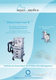
Anesthesia system controlsw WARNINGExplosion Hazard. Do not use <strong>Aespire</strong> systems with flammableanesthetic agents.Do not use antistatic breathing tubes or masks. They can causeburns if you use them near high frequency surgical equipment.321456710981. Breathing system2. Flow controls3. Ventilator / monitoring display4. Dovetail rails5. Vaporizer6. Pipeline pressure gauge(s) (upper row)7. System switch8. Cylinder pressure gauge(s) (lower row)9. Brake10. O2 flush button1009-0486-000 03/03 1
Turn on the systemStep 1Connect the power cord to awall outlet.• The mains indicatorcomes on when ACpower is connected.Step 2Set the system switch to on(|).• The display shows thepower-up screen, andthe system does aseries of self tests.• If the self tests pass, thenormal displayappears.• If a test fails, the screenshows an alarm.(On)2 S/5 <strong>Aespire</strong> Quick Reference Guide
Set the ventilation modeVolume ControlPressure Mode6255or:30625or51009-0486-000 03/03 5
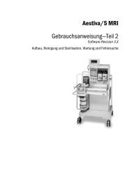
Vaporizer controls1234AA.43.0511. Lock Lever2. Concentration Control and Release3. Tec 6 Plus4. Tec 71009-0486-000 03/03 7
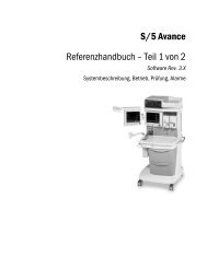
Breathing system components1716151413112111098765 4 3 28 S/5 <strong>Aespire</strong> Quick Reference Guide
18AB.74.p027191. Expiratory check valve (unidirectional valve)2. Auxiliary common gas outlet (ACGO) switch3. ACGO4. Inspiratory check valve (unidirectional valve)5. Inspiratory flow sensor or flow port adapter / patient connection (circuitconnections)6. Canister (carbon dioxide absorbent)7. Canister release8. Expiratory flow sensor or flow port adapter / patient connection (circuit connections)9. Leak test plug10. Breathing system release11. Manual bag port12. APL (adjustable pressure-limiting) valve13. Bag/mechanical ventilation switch14. Bellows assembly (mechanical ventilation)15. Sample gas return port16. Pressure gauge (airway)17. Serial port18. Bag arm (optional)19. Manual Bag (optional; no bag arm)1009-0486-000 03/03 9
Set the alarm loudness1 55510 S/5 <strong>Aespire</strong> Quick Reference Guide
Show or hide alarm limits and unitsShowHideHide1009-0486-000 03/03 11
Turn the Volume Alarms on or offw WARNINGDo not turn off volume alarms with a spontaneously breathingpatient. The system will not alarm for low volume.Use this control during manual ventilation when constant attention is beingkept on the patient’s ventilation.Vol Alarms OnUse the End Case key (on control panel) to prevent volume apnea and alarmsbetween cases. These alarms will reactivate if two breaths are detected within30 seconds.12 S/5 <strong>Aespire</strong> Quick Reference Guide
Set alarm limits100 95951009-0486-000 03/03 13
Set an audible alarm for circuit leaksAudio OnAudio OffAlarm SettingsO2 18 100VE Off OffVTE Off OffCircuit Leak Audio OffCardiac Bypass NoGo to Main Menu14 S/5 <strong>Aespire</strong> Quick Reference Guide
Set Cardiac BypassNote: Mechanical ventilation must be off. When mechanical ventilation isturned back on, Cardiac Bypass returns to the No setting and monitoring isavailable.RAlarm SettingsO2 25 100VE 6.0 7.0VTE 600 700Circuit Leak Audio OnCardiac Bypass NoGo to Main MenuAlarm SettingsO2NoVEIn ProgressVTECircuit LeakCardiac BypassGo to Main Menu1009-0486-000 03/03 15
NoIn progressNoIn progress16 S/5 <strong>Aespire</strong> Quick Reference Guide
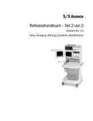
About Alarmsw WARNINGIf an alarm occurs, safeguard the patient first, beforeperforming troubleshooting or doing repair procedures.The area at the top of the display (1) shows alarm information. If there are morethan four alarms at the same time, the lower priority alarms cycle every twoseconds.1Alarm priority depends on the level of risk to the patient. High priority alarmsrequire immediate attention. If an alarm is related to control settings, the limitsflash and a box appears around the parameter.Priority Alarm tone Alarm silence NoteHigh2 bursts of 5 tones,pause, repeat120 seconds orcannot be silencedReverse video.Screen showselapsed timeMedium3 tones, 25 secondpause, repeat120 seconds ----Low Single tone Tone does not repeat ----Alarm messages have three general causes:1. Malfunctions. Some malfunctions cause reduced function (for example noPEEP). Others prevent mechanical ventilation (Minimum shutdown).2. Patient monitoring. These are high and low limit settings that you adjust.3. Informational. Control settings or system conditions can change operation.For example, if the audible circuit leak alarm is Off, the screen shows “CircuitLeak Audio Off” as a low priority alarm.1009-0486-000 03/03 17
Alphabetical list of alarm messagesThe instructions in this section tell you what you can do:• During a case to protect the patient.• After the case to repair a problem.This table does not include operator instructions.There are two special types of alarms:• Minimum monitoring alarms stop mechanical ventilation.• Minimum shutdown alarms stop mechanical ventilation and monitoring.Message Priority Cause Action/Concerns Repair12 Hour TestwBatteryCharging wCal FlowSensorsCheck FlwSensors wLowLowLowMedium(low afteracknowledge)System in use formore than 12 hourswithout a power-upself test.Battery is not fullycharged. If powerfails, the totalbackup time will be< 30 minutes.The last flow sensorcalibration failed.System hasdetected animproper flowpattern in thebreathing circuit.At end of case,move the systemswitch from On toStandby to On.Leave the systemplugged in tocharge the battery.Calibrate the flowsensors.Look for water inthe flow sensortubes and dry ifnecessary.Replace sensor ifnecessary.Are the flowsensors correctlyinstalled?Water build up inthe flow sensortubes?Is a flow sensortube cracked orbroken?Improper checkvalve operation?Not necessary.Informational.- - -Contact aqualified servicerepresentative ifcalibrating orreplacing thesensor does notcorrectproblem.Inspect one wayvalves(breathingcircuit module.)Check thecondition of theflow sensor andits tubing.18 S/5 <strong>Aespire</strong> Quick Reference Guide
Message Priority Cause Action/Concerns RepairExp FlowSensor FailExp ReverseFlowInsp FlowSensor FailInsp ReverseFlowInspirationStopped wLow DriveGas PressLowMedium(low afteracknowledge)LowMedium(low afteracknowledge)HighMediumSystem cannot readthe calibration datastored in thesensor.Flow through theexpiratory sensorduring inspiration(for 6 breaths in arow).The system cannotread the calibrationdata stored in thesensor.Flow through theinspiratory sensorduring expiration(for 6 breaths in arow).Drive gas safetyswitch activated(high pressure).The ventilator doesnot detect supplypressure.Low P aw High Paw does not rise atleast 4 cm aboveP min during the last20 seconds.Operationcontinues withreduced accuracy.Look at the checkvalves.Water build up inthe flow sensortubes?Is a flow sensortube cracked orbroken?Operationcontinues withreduced accuracy.Look at the checkvalves.Water build up inthe flow sensortubes?Is a flow sensortube cracked orbroken?Adjust controls.Check systems forblockages.Manually ventilatethe patient.Are circuitconnections Ok?Look at the Pawgauge on theabsorber.Replace the flowsensor.Replace theexpiratory checkvalve.Check the flowsensorcondition.Replace the flowsensor.Replace theinspiratorycheck valve.Check the flowsensorcondition.Contact aqualified servicerepresentative ifproblemcontinues.Make sure thatthe appropriategas supplies (O 2or air) areconnected andpressurized.Look for circuitdisconnection.1009-0486-000 03/03 19
Message Priority Cause Action/Concerns RepairMonitoringOnlyNo O 2pressureOn Battery -Power OK?PatientCircuit Leak?P aw < -10cmH2OP insp NotAchievedMediumHigh(cannotbesilenced)Medium(low afteracknowledge)MediumHighLowA severemalfunctionpreventsmechanicalventilation.Other alarms mayalso occur.The O 2 supply hasfailed.The mains supply isnot connected orhas failed and thesystem is usingbattery power.Exhaled volume
Message Priority Cause Action/Concerns RepairPres/Vol MonInactiveServiceCalibrationwSustainedAirwayPressureSustainedPawMedium(low afteracknowledge)LowMin.shutdown(High)HighOutlet selectionswitch is set to aux.gas outlet.Internal calibrationsare necessary formaximum accuracy.P aw > 100 cm H2Ofor 10 seconds.Paw > sustainedpressure limit for 15seconds. *Connect the patientcircuit to the aux.gas outlet or set theswitch to thecommon gas outletfor normaloperation.The system isoperational.Check tubing forkinks, blockages,disconnects.Check tubing forkinks, blockages,disconnects.- - -Contact aqualified servicerepresentative.Calibrate theflow sensors.Calibrate theflow sensors.* The sustained pressure threshold is calculated from the pressure limitsetting. The sustained limit is calculated as follows:Mechanical Ventilation On - Volume Mode• For P limits ≤ 30 cm H 2O; the sustained pressure limit is 6 cm H 2O plusSet PEEP.• For P limits between 30 and 60 cm H2O; the sustained pressure limit is20% of the Plimit plus Set PEEP.• For P limits ≥ 60 cm H2O; the sustained pressure limit is 12 cm H2O plusSet PEEP.Mechanical Ventilation On – Pressure Mode• Sustained pressure limit is 50% of set Pinsp or 4 cm H2O, whichever isgreater, plus Set PEEPand•Pmax – Pmin must be less than 50% of set Pinsp or 4 cm H2O, whicheveris greater.Mechanical Ventilation Off• For Plimits ≤ 60 cm H2O; the sustained pressure limit is 50% of thePlimit setting.• For P limits > 60 cm H2O; the sustained pressure limit is 30 cm H2O.1009-0486-000 03/03 21
Message Priority Cause Action/Concerns RepairSystemLeak?VentilateManuallyVolumeApneaVol Apnea> 2 minV T Comp OffLowHighMediumHighMedium(low afteracknowledge)Leak detectedbetween ventilatorand patient circuit.A severemalfunctionpreventsmechanicalventilation andmonitoring.Other alarms mayalso occur.No mechanicalbreaths orspontaneousbreaths > 5 mL inlast 30 seconds.No mechanicalbreaths orspontaneousbreaths > 5 mL inlast 120 seconds.The system suppliesthe set breath butcannot adjustventilation forcompliance andresistance losses,etc.Look for leaks inthe absorbersystem.Problem with flowsensors?Ventilate manually.Use a stand-alonemonitor.Cycle system power(On- Standby-On).If the alarm clears,restart mechanicalventilation.Check patient.Bag as needed.Check fordisconnects.If the patient is on aheart lungmachine, selectCardiac Bypass onthe alarm menu.Check patient.Bag as needed.Check fordisconnects.If the patient is on aheart lungmachine, selectCardiac Bypass onthe alarm menu.Adjust V T manuallyand continuewithoutcompensation, orchange to thepressure mode.In pressure modeset P insp.Calibrate theflow sensors.Drain waterbuildup from thebreathingsystem andinspect for leaks(repair).Inspect orreplace flowsensors.Contact aqualified servicerepresentative.- - -- - -Inspect the twoflow sensors.22 S/5 <strong>Aespire</strong> Quick Reference Guide
Message Priority Cause Action/Concerns RepairVT CompDisabledV T NotAchievedMedium(low afteracknowledge)LowA flow sensor hasbeen connected toa non-activeventilatormonitoring feature.Tidal volumemeasured byinspiratory flowsensor < set value 6breaths in a rowafter the firstminute ofmechanicalventilation.VTE > Insp VT Low Expired volume >inspired volume for6 breaths with acircle module.V T DeliveryToo HighLowVT > 20% of setvalue for sixconsecutivebreaths.The VolumeCompensatedDelivery feature isnot active on thissystem.Adjust controls tosupply adequatetidal volumes.Check I:E, P limit,and volumesettings.Check patientcondition.Are the flowsensors correctlyinstalled?Water build-up inthe flow sensortubes?Is a flow sensortube cracked orbroken?Improper checkvalve operation?Reduce fresh gasflow.Contact aqualified servicerepresentativefor activation ofthis feature ifprovided orcontact a <strong>Datex</strong>-Ohmeda salesrepresentativefor purchase ofthis feature.Possible leak.Modify settingsor check forsystem leaks.Inspect one wayvalves(breathingcircuit module.)Replace flowsensors.- - -1009-0486-000 03/03 23
24 S/5 <strong>Aespire</strong> Quick Reference Guide
© 2003 <strong>Datex</strong>-Ohmeda, Inc. All rights reserved Subject to change without notice Printed in USA 03 03 1009 0486 000 A