Accumeasure 500 brochure - MTI Instruments Inc.
Accumeasure 500 brochure - MTI Instruments Inc.
Accumeasure 500 brochure - MTI Instruments Inc.

You also want an ePaper? Increase the reach of your titles
YUMPU automatically turns print PDFs into web optimized ePapers that Google loves.
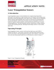
Capacitance Measurement PrinciplesTM<strong>Accumeasure</strong> System measurement technology is based on the principle of parallel plate capacitor measurement.TMThe electrical capacitance formed between an <strong>Accumeasure</strong> probe and a target surface varies as a function of thedistance (gap) between these two surfaces. see Figure 1Capacitance based measurement probes have long been employed as a means of non-contact measurement ofelectrically conductive materials. In a typical system, <strong>MTI</strong>I's capacitance probe acts as one of the plates and thegrounded target the other plate. <strong>MTI</strong>I's amplifier converts the gap's capacitance into a output voltage proportional tothe gap. Capacitive measurements are very stable rivaling interferometer accuracy. The Capacitance is notadversely affected by temperature, humidity and pressure.Figure 1GuardRingCONDUCTINGWIREGROUNDSHELLCOAXIALCABLESENSINGELECTRODED (Gap)GUARDRINGELECTRICFIELDTARGETGROUNDGUARDFIELDSENSINGGAPTARGETGROUNDTo maintain a highly linear response it is important to establish a uniform electric field in the gap. To accomplish this <strong>MTI</strong>I uses a “guarded” probeapproach. All of <strong>MTI</strong>I’s capacitance probes are designed with sufficient guards to protect the sensing area under normal operating conditions.However, the flexibility of <strong>MTI</strong>I’s <strong>Accumeasure</strong> amplifier series allows the system measurement range to be increased up to 10 times. Contact<strong>MTI</strong>I’s Applications Engineers for assistance when extending the range of the capacitive probes. In addition to improving linearity and accuracy,the guard is also used to reduce noise and external influences. Each capacitance probe is driven by a low noise coaxial cable.TMThe <strong>Accumeasure</strong> System measures the electrical impedance of the capacitance between a sensing electrode in the probe and a groundreferencedtarget. The magnitude of the impedance (Z C) is proportional to the reciprocal of the capacitance value as defined by the equation:where: is proportional to the frequency at which the capacitance measurement is performed. = 2 f (f=16kHz)Substituting the equation for capacitance into the impedance equation shows that the impedance is directly proportional to the gap value D, asTMshown in the following equation:So, D is proportional to C, and the <strong>Accumeasure</strong> probe amplifier produces a DC voltage that islinearly proportional to the probe gap impedance (Z ). Any vibration variation shows up as an AC voltage proportional to the amplitude of thecvibration. The amplifier electronic circuitry eliminates the effects of both the probe cable capacitance and the stray capacitance at the edge of theprobe sensing area that could cause non-linearity of the gap and vibration measurements.Accuracy is a function of linearity, resolution, temperature stability and drift, with linearity being the majoritycontributor. Fortunately, the linear response of <strong>MTI</strong>I’s capacitive sensors is very repeatable. Calibration reportsprovide data that can be used to correct for the non-linearity of a system using inexpensive computers andcorrection software.TMThe <strong>Accumeasure</strong> AdvantagesSuperior linearity for sub-nanometer resolution and accuracyExtended system ranges for added measurement flexibility