MSD Tech Line - MSD Powersports
MSD Tech Line - MSD Powersports
MSD Tech Line - MSD Powersports

Create successful ePaper yourself
Turn your PDF publications into a flip-book with our unique Google optimized e-Paper software.
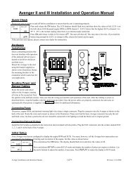
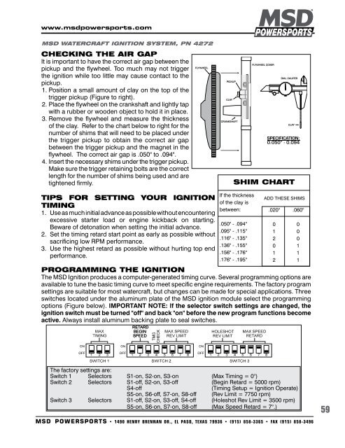
www.msdpowersports.com<strong>MSD</strong> WATERCRAFT IGNITION SYSTEM, PN 4272Checking the Air GapIt is important to have the correct air gap between thepickup and the flywheel. Too much may not triggerthe ignition while too little may cause contact to thepickup.1. Position a small amount of clay on the top of thetrigger pickup (Figure to right).2. Place the flywheel on the crankshaft and lightly tapwith a rubber or wooden object to hold it in place.3. Remove the flywheel and measure the thicknessof the clay. Refer to the chart below to right for thenumber of shims that will need to be placed underthe trigger pickup to obtain the correct air gapbetween the trigger pickup and the magnet in theflywheel. The correct air gap is .050" to .094".4. Insert the necessary shims under the trigger pickup.Make sure the trigger retaining bolts are the correctlength for the number of shims being used and aretightened firmly.SHIM cHARTTips For Setting Your IgnitionTiming1. Use as much initial advance as possible without encounteringexcessive starter load or engine kickback on starting.Beware of detonation when setting the initial advance.2. Set the timing retard start point as early as possible withoutsacrificing low RPM performance.3. Use the highest retard as possible without hurting top endperformance.If the thicknessof the clay isbetween:.050" - .094".095" - .115".116" - .135".136" - .155".156" - .176".176" - .195"ADD THESE SHIMS.020" .060"0 01 02 00 11 12 1PROGRAMMING THE IGNITIONThe <strong>MSD</strong> Ignition produces a computer-generated timing curve. Several programming options areavailable to tune the basic timing curve to meet specific engine requirements. The factory programsettings are suitable for most watercraft, but changes can be made for special applications. Threeswitches located under the aluminum plate of the <strong>MSD</strong> ignition module select the programmingoptions (Figure below). IMPORTANT NOTE: If the selector switch settings are changed, theignition switch must be turned "off" and back "on" before the new program functions becomeactive. Always install aluminum backing plate to seal switches.The factory settings are:Switch 1 Selectors S1-on, S2-on, S3-on (Max Timing = 0°)Switch 2 Selectors S1-off, S2-on, S3-off (Begin Retard = 5000 rpm)S4-off(Timing Setup = Ignition Operate)S5-on, S6-off, S7-on, S8-off (Rev Limit = 7750 rpm)Switch 3 Selectors S1-off, S2-on, S3-off, S4-off (Holeshot Rev Limit = 3500 rpm)S5-on, S6-on, S7-on, S8-off (Max Speed Retard = 7°.)<strong>MSD</strong> POWERSPORTS • 1490 Henry Brennan DR., El Paso, Texas 79936 • (915) 858-3365 • FAX (915) 858-349659