
You also want an ePaper? Increase the reach of your titles
YUMPU automatically turns print PDFs into web optimized ePapers that Google loves.
(01 May 2006) FITNET MK7<strong>Annex</strong> C<strong>Residual</strong> <strong>Stress</strong> <strong>Profiles</strong>C.1 Symbols..................................................................................................................................................2C.2 Introduction............................................................................................................................................4C.3 <strong>Stress</strong> Categorisation ...........................................................................................................................5C.4 Methodology Used to Produce the Compendium..............................................................................5C.5 Plate Butt and Pipe Seam Welds. ........................................................................................................6C.5.1 Longitudinal <strong>Residual</strong> <strong>Stress</strong>es...........................................................................................................6C.5.2 Transverse <strong>Residual</strong> <strong>Stress</strong>es .............................................................................................................7C.6 Plate T-Butt welds .................................................................................................................................7C.6.1 Longitudinal <strong>Residual</strong> <strong>Stress</strong>es...........................................................................................................7C.6.2 Transverse <strong>Residual</strong> <strong>Stress</strong>es .............................................................................................................7C.7 Pipe Butt Welds .....................................................................................................................................8C.7.1 Longitudinal <strong>Residual</strong> <strong>Stress</strong>es...........................................................................................................8C.7.2 Transverse <strong>Residual</strong> <strong>Stress</strong>es .............................................................................................................8C.8 Pipe T-butt welds...................................................................................................................................9C.8.1 Longitudinal <strong>Residual</strong> <strong>Stress</strong>es...........................................................................................................9C.8.2 Transverse <strong>Residual</strong> <strong>Stress</strong>es .............................................................................................................9C.9 Set in Nozzle ........................................................................................................................................10C.9.1 Longitudinal <strong>Residual</strong> <strong>Stress</strong>es.........................................................................................................10C.9.2 Transverse <strong>Residual</strong> <strong>Stress</strong>es ...........................................................................................................10C.10 Set on Nozzle .......................................................................................................................................11C.10.1 Longitudinal <strong>Residual</strong> <strong>Stress</strong>es.........................................................................................................11C.10.2 Transverse <strong>Residual</strong> <strong>Stress</strong>es ...........................................................................................................11C.11 Repair Welds........................................................................................................................................11C.11.1 Longitudinal <strong>Residual</strong> <strong>Stress</strong>es.........................................................................................................12C.11.2 Transverse <strong>Residual</strong> <strong>Stress</strong>es ...........................................................................................................12C.12 Transition Welds..................................................................................................................................13C.13 Weld T Intersections ...........................................................................................................................13C.14 References ...........................................................................................................................................13Appendix C.1 Calculation of the Dimensions of the Yielded Zone ..........................................................32Appendix C.2 More Realistic Level 3 Weld <strong>Residual</strong> <strong>Stress</strong> <strong>Profiles</strong> for Austenitic StainlessSteel Pipe Butt Welds..........................................................................................................................34Appendix C.3 Bibliography ..........................................................................................................................36C.15 Additional Information ........................................................................................................................48C.15.1 <strong>Residual</strong> <strong>Stress</strong>es in Laser and Friction Stir Welded Al-Alloy Plates............................................48C.15.2 Laser Welded Steel Plates..................................................................................................................53C.15.3 Bibliography.........................................................................................................................................62© FITNET 2006 – All rights reserved <strong>Annex</strong> C.1
FITNET FFS –MK7 – <strong>Annex</strong> CC.1 SymbolsWithin this section, the following symbols are used with the dimensions specified below.Q ~qRrWeld pass heat input into workpiece per unit length per unit thickness,Weld torch arc power (current x closed circuit voltage) J/secMean radius of pipe (or radius of chord for Pipe T-Butt), mmRadius of brace in pipe T-Butt, mmQ ~ = η[(q /2v) / t],J / mmr0Dimensions of the yield zone for a thin plate, mmTtvWPlate (or chord) thickness for T weld joint, mmPlate or pipe thickness (or thickness of brace for Pipe T-Butt), mmWeld torch advance rate, mm/secWidth of the weld at surface, mmy0Dimensions of the yield zone for a thick plate, mmzPosition through-thickness, mmzrDepth of a repair weld, mmz0Size of yield zone below repair weld, mmδ Heat input sinusoid correlation factor for pipe butt weld Level 3 longitudinal stressϕηθHeat input bending correlation factor for pipe butt weld Level 3 transverse stressWeld process efficiencyHeat input sinusoid correlation factor for pipe butt weld Level 3 transverse stressσyTypical 1 room temperature yield strength of material, MPa. For austenitic material, the typical 1%proof stress should be used. For ferritic material the typical yield point or typical 0.2% proof stress isappropriateσ Lower of , σ ),*y(yp ywσ MPa+σ yGreater of (yp,σyw),σ MPaσypParent metal typical yield strength, MPaσywWeld metal typical yield strength, MPaLσRLongitudinal residual stress, MPaL,OσRLongitudinal residual stress at outer surface, MPa1 Typical rather than lower bound room temperature yield strength properties should be used. A typical value is defined tobe a mean estimate of the yield strength, as used to construct the failure assessment diagram.<strong>Annex</strong> C.2© FITNET 2006 – All rights reserved
(01 May 2006) FITNET MK7L,BσRLongitudinal residual stress at bore surface, MPaTσRTransverse residual stress, MPaT,OσRTransverse residual stress at outer surface, MPaT,BσRTransverse residual stress at bore surface, MPa© FITNET 2006 – All rights reserved <strong>Annex</strong> C.3
FITNET FFS –MK7 – <strong>Annex</strong> CC.2 IntroductionThis section presents a compendium of recommended residual stress profiles for a range of differentconfigurations of as-welded structural weldments. Section II.7 distinguishes between three types of throughwallresidual stress profile (Levels 1–3). Level 1 profiles readily enable an initial conservative assessment of adefect to be made by assuming an uniform, tensile residual stress field equal in magnitude to the maximumyield stress of the plate or weld material (Section II.7.5.1). Level 2 profiles provide a more detailed butconservative through-wall characterisation. Level 3 profiles represent a more realistic estimate of the specificweld through-wall residual stress distribution based on experimental measurements combined with detailedanalysis. A majority of the residual stress profiles recommended here are essentially upper bounds toavailable measured and predicted residual stress data, that is they are classified as Level 2 in Section II.7.Although these through-wall profiles do not represent realistic self-balancing stress distributions, they do givea starting point in the quantification of residual stresses that is less conservative than a Level 1 assumption, inalmost all cases. More realistic residual stress through-wall profiles (Level 3) for austenitic stainless steel pipebutt welds are included in Appendix C.2.A compendium of weld residual stress profiles supporting R6 assessments was first compiled in 1991 [C.1].Since then the compendium has been continually reviewed and updated [C.2], [C.3] and [C.4]. The reviewperformed under the EC funded SINTAP project [C.4] provided a consensus of residual stress profiles basedon [C.3] and BS7910 [C.5]. Subsequently, the recommended distributions for ferritic and austenitic steel pipegirth welds have been revised in BS7910 Amendment No.1 [C.6]. A further literature review has beenperformed since the release of [C.4] and [C.6], and the profiles for ferritic plate butt welds and pipe butt weldsupdated. This section provides the latest recommended residual stress profiles for the fracture assessment ofdefects in welded structures.Following a discussion of stress categorisation in Section C.3, and the methodology used to develop the Level2 profiles in Section C.4, the compendium of upper bound profiles is set out in Sections C.5-13, supported byfigures for each geometry considered. The geometries considered are:C.5 Plate Butt and Pipe Seam WeldsC.6 Plate T-Butt WeldsC.7 Pipe Butt WeldsC.8 Pipe T-Butt WeldsC.9 Set-in NozzlesC.10 Set-on NozzlesC.11 Repair WeldsC.12 Transition WeldsC.13 Weld T-IntersectionsFor some of these profiles, it is necessary to calculate the parameters of the yielded zone at the weld andthese calculations are set out in Appendix C.1. Some more realistic through-wall profiles (Level 3) foraustenitic stainless steel pipe butt welds are included in Appendix C.2. Section C.14 contains references citedin the text. However, there is a much more extensive bibliography on which the profiles are based and, forcompleteness, this is included here in Appendix C.3.<strong>Annex</strong> C.4© FITNET 2006 – All rights reserved
(01 May 2006) FITNET MK7C.3 <strong>Stress</strong> CategorisationThe literature surveys undertaken for the assembly of this compendium indicate that residual stressdistributions are made up of two components. The first is directly attributable to the welding process, arisingdue to the thermal contractions and phase changes that occur in the weldment. The other component arisesdue to mismatches and restraints within the structure itself. This, second component is obviously variablefrom case to case.Section I.5 draws attention to the classification of stresses for use in assessments and requires that allstresses should be classified into primary, σ ps, and secondary, σ , stresses. Primary stresses are those whichcontribute to collapse, such as applied loads or pressures. If there is significant elastic follow-up within astructure, then some displacement-controlled stresses must also be classified as primary stresses.Secondary stresses are those that are self equilibrating across the section, that is, the net force or bendingmoment across a section due to the secondary stresses is zero.Wherever possible, the residual stress distributions given in this section exclude long-range structural restrainteffects. If long-range residual stresses that exhibit significant elastic follow-up are present, they must beconsidered separately, and, if necessary, treated as primary stresses. Section II.7.4.1 provides detailedguidance on the classification of weld residual stresses for fracture assessment.C.4 Methodology Used to Produce the CompendiumIn developing the Level 2 profiles summarised below in Sections C.5-13, data obtained for each geometrywere fitted to upper bound tensile profiles. As a result, the quoted profiles are not, in general, selfequilibratingacross the weld section. However, the individual profiles from which the sum of the data wasobtained were self equilibrating so that the profiles given in this compendium may be treated as conservativeestimates of secondary stresses in an assessment.In Sections C.5-13, equations for the upper bound fits are presented, but, due to the quantity and scatter ofdata, the original data points are not shown.The residual stress profiles are given as transverse stresses, σ T R(stresses normal to the weld run) andLlongitudinal, σR(stresses parallel to the weld run). The variation of stresses with through wall distance andnormal distance from the weld centre-line are shown. <strong>Stress</strong>es acting in the through thickness direction areassumed to be negligible.Two approaches for defining Level 2 residual stress profiles are provided in Sections C.5-13 depending on theavailable information about welding conditions.1) If the welding conditions are known or can be estimated, then residual stress profiles given in this sectionmay be used in association with the size parameters of the plastic zone (r 0 , y 0 ) given in Appendix C.1.2) If the welding conditions are unknown, then the given polynomial functions should be used.The as-welded Level 2 residual stress profiles for ferritic steel joints are valid for the range of thickness, yieldstrength and heat input given in Table C.1.Longitudinal residual stresses are normalised with respect to the greater of the typical room temperature yield+strengths of the weld or plate materials, σ y. Transverse residual stresses are normalised with respect to thelower of the typical room temperature yield strengths of the weld or plate materials,the three cases listed below:*σy, with the exception of© FITNET 2006 – All rights reserved <strong>Annex</strong> C.5
FITNET FFS –MK7 – <strong>Annex</strong> C(i)(ii)defects at repair welds;defects at weld intersections;(iii) shallow defects with a depth no greater than one weld run.In these cases, transverse residual stresses for fracture assessment should be based on the greater of theparent or weld metal yield strength.When interpreting the profiles for austenitic steels, it is conservative to use the room temperature 1% proofstress properties. This allows for material work hardening and the large variability observed in 0.2% proofstress properties for austenitic materials.Once the room temperature residual stress distribution has been defined, Section II.7.3 describes how toaccount for mechanical stress relief, the assessment temperature and historical operation at hightemperatures in the fracture assessment.The through thickness stress profiles are normalised with respect to plate thickness.For each geometry considered, there are associated Figures (a) to (d) which represent the variation ofresidual stresses as follows:(a) variation of longitudinal residual stresses at the surface;(b) variation of longitudinal residual stresses through the thickness;(c) variation of transverse residual stresses at the surface;(d) variation of transverse residual stresses through the thickness.A schematic illustration of the weld geometry is shown in each figure, which illustrates the longitudinal andtransverse directions and various dimensional parameters that are used in Figures (a) to (d).For all geometries, the figures, in conjunction with the comments in the appropriate part of the following text,should provide sufficient information to generate a conservative residual stress profile.For fracture assessment where adequate reserve margins are not obtained using the upper bound Level 2profiles recommended in Sections C.5-13, more detailed (Level 3) residual stress distributions should bedetermined, see Section II.7.5.3. For austenitic stainless steel pipe butt welds, Level 3 through-wall profilescan be estimated using the formulation described in Appendix C.2. For other weld geometries, the referenceslisted in Appendix C.3 can be consulted to help characterise and substantiate more realistic Level 3 profilesfor the specific welded joint, materials and welding conditions of interest.C.5 Plate Butt and Pipe Seam Welds.The depth, z, used to define the through-wall profiles, is measured from the surface on which the last bead isdeposited.C.5.1 Longitudinal <strong>Residual</strong> <strong>Stress</strong>esSurface profiles based on the recommendations of Leggatt [C.7] are shown in Figure C.1(a) for ferritic,austenitic and aluminium material, and for single and double sided welds. The calculation of the parameters<strong>Annex</strong> C.6© FITNET 2006 – All rights reserved
(01 May 2006) FITNET MK7r0and0(i.e. W 1 >W 2 ).y is given in Appendix C.1. If the weld is asymmetric, side one is the side with the widest weld faceThe through thickness profile is shown in Figure C.1(b) for ferritic and austenitic steels. The recommendedprofiles are:Ferritic Steels:σ L/ σ (z / ywt) = 1RAustenitic Steelsσ L/ σ (z / ywt) = 0.95 + 1.505(z/t) - 8.287(z/t)2 + 10.571(z/t) 3 - 4.08(z/t) 4RC.5.2 Transverse <strong>Residual</strong> <strong>Stress</strong>esThe surface profiles are shown in Figure C.1(c). For pipe seam welds and unrestrained plates the profile isbased on the recommendations of Leggatt [C.7]. For restrained plates the profile of Mathieson [C.1] isretained.The recommended transverse through thickness profile is given in Figure C.1(d). This profile is an upperbound to data obtained from both ferritic and austenitic steels.Ferritic and Austenitic Steels:σ T/ σ *(z / t) =1-0.917(z/t)-14.533(z/t)2 +83.115(z/t) 3 -215.45(z/t) 4 +244.16(z/t) 5 -96.36(z/t) 6RyC.6 Plate T-Butt weldsC.6.1 Longitudinal <strong>Residual</strong> <strong>Stress</strong>esThe longitudinal surface profiles recommended by Leggatt [C.7] are shown in Figure C.2(a) for ferritic,austenitic and aluminium material and for two different weld preparations. The calculation of the parametersr 0 and y 0 is given in Appendix C.1. If the weld is asymmetric, side one is the side with the widest weld face(i.e. W 1 >W 2 ).The through thickness profile is shown in Figure C.2(b), where the parameter r o is calculated according toAppendix C.1. If the welding conditions are unknown, then the following profile may be used for ferritic steel:Ferritic SteelLσR/σ yw (z/t) = 0.75 + 4.766(z/t) - 26.696(z/t) 2 + 38.11(z/t) 3 - 16.82(z/t) 4C.6.2 Transverse <strong>Residual</strong> <strong>Stress</strong>esFor transverse surface stresses the profile of Mathieson [C.1] is still retained. Figure C.2(c) shows therecommended surface profile, where W is defined in Figure C.2(a).© FITNET 2006 – All rights reserved <strong>Annex</strong> C.7
FITNET FFS –MK7 – <strong>Annex</strong> CFigure C.2(d) shows the through wall distribution, where the parameter r 0is calculated according to AppendixC.1.C.7 Pipe Butt WeldsThere have been a number of proposals in structural integrity procedures and published compendia for thethrough-wall residual stress profiles to use in fracture assessments for pipe butt welds. The upper bound(Level 2) residual stress profiles recommended here for stainless steel welds are supported by extensivemeasurements and numerical predictions [C.8]. More realistic through-wall residual stress profiles (Level 3)are defined in Appendix C.2 for improved fracture assessments of stainless steel pipe welds.C.7.1 Longitudinal <strong>Residual</strong> <strong>Stress</strong>esThe longitudinal surface profiles of Leggatt [C.7] for ferritic steel, austenitic steel and aluminium arerecommended for single-sided and double-sided welds, see Figure C.3(a). The calculation of the parametersr 0 and y 0 is given in Appendix C.1. If the weld is asymmetric, side one is the side with the widest weld face(i.e. W 1 >W 2 ).The longitudinal through wall residual stress distribution for both ferritic and austenitic steels is given as aL,OL,Blinear profile defined by σRat the outer surface and σRat the bore, see Figure C.3(b), where the surfacevalues are defined byσL,OR= σywσL,BR= A σbywwhere: A b = 1 0
(01 May 2006) FITNET MK7z = distance from inner surface of pipe, mmt = pipe thickness, mmFor high heat input ferritic and austenitic steel welds where [(q/v)/t]>120 J/mm 2T *23σR= σy[1.00− 0.22(z / t) − 3.06(z / t) + 1.88(z / t) ]For medium heat input ferritic steel welds where 50 J/mm 2 2, the profiles for plate T-butt welds are recommended.The R/r ratios for the pipe on pipe geometries varied from 1.5 to approximately 2. The profiles recommendedhere should be used with caution outside this range. If the radii differ by a large amount (say a factor of 5)then the profiles presented for plate T-butt welds should be considered as an alternative.C.8.1 Longitudinal <strong>Residual</strong> <strong>Stress</strong>es.The surface profile for ferritic steel, austenitic steel and aluminium is shown Figure C.4(a). The calculation ofthe parameters r 0and y0is given in Appendix C.1.The through thickness variation of longitudinal residual stresses away from the weld centre line is given inFigure C.4(b). This is an upper bound to data obtained from ferritic steels in pipe on plate and tubular T and Ynode geometries. Caution should be used in applying this distribution to austenitic welds:σ / σ (z/t) = 1.025+3.478(z/t)-27.861(z/t) 2 +45.788(z/t) 3 -21.8(z/t) 4LRywC.8.2 Transverse <strong>Residual</strong> <strong>Stress</strong>esThe surface profile given in Figure C.4(c) is the same as that presented in Figure C.2(c).© FITNET 2006 – All rights reserved <strong>Annex</strong> C.9
FITNET FFS –MK7 – <strong>Annex</strong> CThe through thickness variation of transverse residual stresses away from the weld toe is given in FigureC.4(d). This is an upper bound to data obtained from ferritic steels in pipe on plate and tubular T and Y nodegeometries. Caution should be used in applying this distribution to austenitic welds since no data fromaustenitic steel were obtained:σ / σ (z/t) = 0.97+2.327(z/t)-24.125(z/t)2 +42.485(z/t) 3 -21.087(z/t) 4TR*yC.9 Set in NozzleThe surface residual stress profiles (Figures C.5(a) and C.5(c)) are based on the recommendations of Leggatt[C.7]. The stresses on line A i A o are based on the general observation that longitudinal stresses in butt weldscan be of weld yield stress magnitude throughout the thickness. This agrees with the Sanderson [C.2]recommendations for cylinder-to-dome welds. The distributions for longitudinal and transverse stresses online B i B o are the same as those recommended for plate T-butt welds. This distribution only applies for defectsinitiating at or near the toe of the weld.C.9.1 Longitudinal <strong>Residual</strong> <strong>Stress</strong>esThe surface profile for ferritic steel, austenitic steel and aluminium is shown in Figure C.5(a). The calculationof the parameters r 0and y0is given in Appendix C.1.The through thickness profiles are shown in Figure C.5(b) for the nozzle (Line B i B o ) and vessel (Line A i A o ).The calculation of the parameter r 0is given in Appendix C.1.C.9.2 Transverse <strong>Residual</strong> <strong>Stress</strong>esThere is currently no profile proposed for surface transverse residual stress because there are insufficientTdata available and it is geometry sensitive. For the interim, a uniform stress σRequal to the lower of theparent or weld metal yield strength should be considered.The through thickness profiles are shown in Figure C.5(d) for the nozzle (Line B i B o ) and Vessel (Line A i A o ).The distribution of transverse stress on A i A o is based on the recommendation in [C.2] for a nozzle-cylinderweld.<strong>Annex</strong> C.10© FITNET 2006 – All rights reserved
(01 May 2006) FITNET MK7C.10 Set on NozzleThe surface residual stress profiles (Figures C.6(a) and 6(c)) are based on [C.7]. The stresses on line A i A oare based on the general observation that longitudinal stresses in butt welds can be of weld yield stressmagnitude throughout the thickness. This agrees with the Sanderson [C.2] recommendations for cylinder-todomewelds. The distributions for longitudinal and transverse stresses on line B i B o are the same as thoserecommended for plate T-butt welds. This distribution only applies for defects initiating at or near the toe ofthe weld.C.10.1 Longitudinal <strong>Residual</strong> <strong>Stress</strong>esThe surface profile for ferritic steel, austenitic steel and aluminium is shown in Figure C.6(a). The calculationof the parameter y0is given in Appendix C.1.The through thickness profiles are shown in Figure C.6(b) for the nozzle (Line A i A o ) and vessel (Line B i B o ).The calculation of the parameter r 0is given in Appendix C.1.C.10.2 Transverse <strong>Residual</strong> <strong>Stress</strong>esThere is currently no profile proposed for surface transverse residual stress because there are insufficientTdata available and it is geometry sensitive. For the interim, a uniform stress σRequal to the lower of theparent or weld metal yield strength should be considered.The through thickness profiles are shown in Figure C.6(d) for the nozzle (Line A i A o ) and vessel (Line B i B o ).The calculation of the parameter r 0is given in Appendix C.1.C.11 Repair WeldsRepair welds are usually introduced into structures, either to remedy initial fabrication defects found incastings or welds by routine inspection, or to rectify in-service degradation of components. <strong>Residual</strong> stressesintroduced by deep repair welds tend to dominate any weld residual stresses remaining from an original weld,in the vicinity of the repair. Therefore, the recommended profiles for repair welds that follow can often be usedfor fracture assessment irrespective of the fabrication history. However, when the significance of the originalresidual stress field or original weld metal properties is uncertain, a sensitivity fracture assessment should beperformed using a residual stress profile for the original weld.The sizes of repairs can range from being shallow and short, to deep and long, sometimes penetrating thewall or extending along the entire length of an original weld. The repairs can be completely embedded in anoriginal weld, transversely offset from the original weld centre-line, or can transversely span and encompassthe entire original weld.The information presented here is generally applicable to short repair welds. As short repairs tend to inducehigher residual stresses than long repairs, the recommended profiles should be bounding for repairs of alllengths. The profiles may be excessively conservative for deep repairs centrally embedded in the originalweld and extending the full length of the weld. In this case, the residual stress profile for the original weld islikely to be more appropriate.The recommended transverse and longitudinal through-thickness residual stress profiles, which are identicalto each other, are illustrated in Figures C.7(b) and (d) and can be used for any length of repair.© FITNET 2006 – All rights reserved <strong>Annex</strong> C.11
FITNET FFS –MK7 – <strong>Annex</strong> CThe surface profile presented in Figure C.7(a) is applicable to short repairs. The surface profile in FigureC.7(c) must be used only for a full length repair.C.11.1 Longitudinal <strong>Residual</strong> <strong>Stress</strong>esThe recommended surface profile for ferritic steel, austenitic steel and aluminium is given in Figure C.7(a).The calculation of the parameters r 0 and y 0 is given in Appendix C.1.The through thickness profile is given in Figure C.7(b). Over the depth of the repair, z r , the stress should betaken as the greater yield stress of the parent plate, original weld or repair weld. Below the repair, the residualstress reduces linearly with distance to zero at a distance z 0below the root of the repair. The distancez0defines the size of the yield zone below the repair and is related to the heat input of the repair weld rootpasses.σ / σ (z/t) = 1 for z < z rLR+yσ / σ (z/t) = (z 0 +z r -z)/ z 0 for z r < z < (z r +z 0 )LR+yσ / σ (z/t) = 0 for z > (z r +z 0 )LR+ywherez r = the depth of the repair, mmz 0 = r 0 as defined by Appendix C.1 equation (a), substituting the yield stress,the parent or weld metal typical yield strength) forσyp.*σy(equal to the lower ofC.11.2 Transverse <strong>Residual</strong> <strong>Stress</strong>esThe recommended surface profile for ferritic steel is given in Figure C.7(c). The through thickness profile isgiven in Figure C.7(d). Over the depth of the repair, z r , the stress should be taken as the greater yield stressof the parent plate, original weld or repair weld. Below the repair, the residual stress reduces linearly withdistance to zero at a distance z 0 below the root of the repair. The distance z 0 defines the size of the yield zonebelow the repair and is related to the heat input of the repair weld root passes.σ / σ (z/t) = 1 for z < z rTR+yσ / σ (z/t) = (z 0 +z r -z)/ z 0 for z r < z < (z r +z 0 )TR+yσ / σ (z/t) = 0 for z > (z r +z 0 )TR+ywherez r = the depth of the repair, mmz 0 = r 0 as defined by Appendix C.1 equation (a), substituting the yield stress,the parent or weld metal typical yield strength) forσyp.*σy(equal to the lower of<strong>Annex</strong> C.12© FITNET 2006 – All rights reserved
(01 May 2006) FITNET MK7C.12 Transition WeldsVery little information was found concerning residual stresses in transition welds. The only references thatwere found concerned a pipe butt transition weld and a nozzle to safe end transition weld. The surfaceprofiles shown in Figures C.8(a) and C.8(c) are bounded by the surface profiles of normal pipe butt welds (seeFigures C.4(a) and C.4(c)). In considering transition welds of other geometries, it is suggested that thesurface profile associated with that particular geometry for austenitics may be used with caution. As for thedistributions in Figures C.8(a) and C.8(c), the residual stress in the ferritic material will be zero for all othergeometries.As a further refinement, the longitudinal residual stress in the ferritic parent plate along the austenitic-ferriticfusion boundary might be considered to be zero. Also, the transverse residual stress in the ferritic parentplate might be considered to fall off to zero within one plate thickness from the fusion boundary. Cautionshould be used with this approach, however, since there are no supporting data.C.13 Weld T IntersectionsThe only information that could be found concerning weld intersection residual stress profiles concerned thestresses at the intersection itself. At any intersection, one weld must be continuous and one weld mustterminate in order to join or cross the other (continuous) weld. Two treatments are suggested for theassessment of residual stress:If the terminating weld is completed first, which is the normal practice, then the intersection has noparticular significance and each weld is treated as it normally would be for the relevant geometry (i.e. theeffect of the intersection should be ignored).If the terminating weld is completed last, than the residual stress profiles must be assumed to be uniform,tensile through the thickness and of weld metal yield stress magnitude.C.14 References[C.1] P A R Mathieson, A compendium of as-welded residual stress profiles, Nuclear Electric ReportTD/SIB/MEM/0233 (1991).[C.2] D J Sanderson, Recommendations for revised compendium of residual stress profiles for R6, AEATechnology Report AEA-TSD-0554 (1996).[C.3] S K Bate and D J Sanderson, Compendium of residual stress profiles for R6, AEA Technology Report,AEAT-2208, (1997).[C.4] J Y Barthelemy, Structural Integrity Assessment Procedures for European Industry SINTAP Task 4,Compendium of <strong>Residual</strong> <strong>Stress</strong> <strong>Profiles</strong>, Institut de Soudure (1999).[C.5 BS 7910, Guide on methods for assessing the susceptibility of flaws in structures, BSi, London (1999).[C.6] BS7910:1999 Incorporating Amendment No.1, Guide on methods for assessing the acceptability offlaws in metallic structures, BSi, London (2000).[C.7] R Leggatt, Recommendations for revised surface residual stress profiles, TWI Report SINTAP/TWI/4-3,88269/4-3/98 (1998).[C.8] P J Bouchard, Validated residual stress profiles for fracture assessments of stainless steel pipe girthwelds, British Energy Report E/REP/ATEC/0025/GEN/01 (2001).[C.9] European Standard EN 1011-1:1998, Welding – recommendations for welding of metallic materials –Part 1: general guidance for arc welding, CEN, Brussels (1998).© FITNET 2006 – All rights reserved <strong>Annex</strong> C.13
FITNET FFS –MK7 – <strong>Annex</strong> COther general references are:H F Devonshire, Investigation in support of validation and verification of Nuclear Electric memorandumTD/SIB/MEM/0233, AEA Technology Report AEA-RS-4242 (1992).S K Bate, D Green and D Buttle, A review of residual stress distributions in welded joints for the defectassessment of offshore structures, HSE – Offshore Technology Report, OTH 482 (1997).B Brickstad and B L Josefson, A parametric study of residual stresses in multi-pass butt-welded stainlesssteel pipes, Int J Pres Ves Piping 75, 11-25 (1998).<strong>Annex</strong> C.14© FITNET 2006 – All rights reserved
(01 May 2006) FITNET MK7Table C. 1 Validity ranges for as-welded residual stress distributions in ferritic steelsGeometryThickness(mm)YieldStrength(MPa)Plate Butt Welds 24 - 300 310 - 740 1.6 – 4.9Pipe Circumferential Butt Welds 9 - 84 225 - 780 0.35 – 1.9Pipe Seam Welds 50 - 85 345 - 780 Not knownT butt Welds 25 - 100 375 - 420 1.4Tubular and pipe to plate welds 22 - 50 360 - 490 0.6 – 2.0Repair Welds 75 - 152 500 - 590 1.2 – 1.6Electrical Heat Input per UnitLength (KJ/mm)© FITNET 2006 – All rights reserved <strong>Annex</strong> C.15
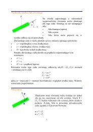
FITNET FFS –MK7 – <strong>Annex</strong> CMaterial: Ferritic and Austenitic steels and Aluminium (only (a))GeometryW 1W 2W 2W 1W 2W 2(a) Longitudinal Surface <strong>Residual</strong> <strong>Stress</strong>,Lσ Rσ yw σ ywThin material (r 0 >t)r 0 W r 0W 1Side 1: W = W 1Side 2: W = W 2Figure C.1 - Plate butt and pipe seam welds<strong>Annex</strong> C.16© FITNET 2006 – All rights reserved
(01 May 2006) FITNET MK7(c) Transverse Surface <strong>Residual</strong> <strong>Stress</strong>,Tσ RSide 1: W = W 1*Side 2: W = W 2σ*yσ yunrestrained platesand(b) Longitudinal Through-Thickness <strong>Residual</strong> <strong>Stress</strong>,restrained platesLσRDistribution− σ yw+ σywLσR / σyw(z / t) = 1L234σR/ σyw(z/t) = 0.95 + 1.505(z/t) -8.287(z/t) + 10.571(z/t) - 4.08(z/t)(d) Transverse Through-Thickness <strong>Residual</strong> <strong>Stress</strong>,TσRDistribution*− σ y*+ σ yALL STEELSEquationsσT *23R/ σy(z/t) = 1.0 - 0.917(z/t) -14.533(z/t) + 83.115(z/t)456Figure C.1 - (cont)© FITNET 2006 – All rights reserved <strong>Annex</strong> C.17
FITNET FFS –MK7 – <strong>Annex</strong> CMaterial: Ferritic and Austenitic steels and Aluminium (only (a))Geometry(a) Longitudinal Surface <strong>Residual</strong> <strong>Stress</strong>,σ ywSide 1: W = W 1Side 2: W = W 2LσRσ ywW 2W 1W 3WWWSide 1: W = W 1 , σ y = σ ywSide 2: W = W 2 , σ y = σ ywFigure C.2 - Plate T-butt welds<strong>Annex</strong> C.18© FITNET 2006 – All rights reserved
(01 May 2006) FITNET MK7(c) Transverse Surface <strong>Residual</strong> <strong>Stress</strong>,TσR(b) Longitudinal Through-Thickness <strong>Residual</strong> <strong>Stress</strong>,LσRC..1.1.1.1Di+ σ yw(d) Transverse Through-Thickness <strong>Residual</strong> <strong>Stress</strong>,TσRDistributionTTσ Rσ*y=lower of( σyw, σyp)Figure C.2 - (cont)© FITNET 2006 – All rights reserved <strong>Annex</strong> C.19
FITNET FFS –MK7 – <strong>Annex</strong> CMaterial: Ferritic, Austenitic Steels and Aluminium (only (a))GeometryW 1W 2W 1W 2L(a) Longitudinal Surface <strong>Residual</strong> <strong>Stress</strong>, σRDistributionσ yw σywThick material (r 0 ≤t)(c) Transverse Surface <strong>Residual</strong> <strong>Stress</strong>,TσRThin material (r 0 >t)Figure C 3 - Pipe butt welds<strong>Annex</strong> C.20© FITNET 2006 – All rights reserved
(01 May 2006) FITNET MK7(b) Longitudinal Through-Thickness <strong>Residual</strong> <strong>Stress</strong>,LσROUTERσL,0R= σINNEREquationsywL,BσR= Abσywwhere : Ab= 10 < t ≤ 15mmAb= 1 − 0.0143 (t −15)15mm < t ≤ 85mmAb= 0t > 85mm(d) Transverse Through-Thickness <strong>Residual</strong> <strong>Stress</strong>,OUTERz+σ y*Tσ RINNERDistribution EquationsFor high heat input ferritic and austenitic welds where [(q/v)/t]>120 J/mm 2T*σ R = σ y [1.00 − 0.22(z / t) − 3.06(z / t) + 1.88(z / t) ]2For medium heat input ferritic welds where 50 J/mm 2
FITNET FFS –MK7 – <strong>Annex</strong> CMaterial: Ferritic, Austenitic Steels (caution for (b), (c), (d)) and Aluminium (only(a))(a) Longitudinal Surface <strong>Residual</strong> <strong>Stress</strong>,LσRDistributionLσ RLσ Rσ ywσ ywThick material (r 0 ≤t)Thin material (r 0 >t)Figure C.4 - Pipe-T-butt welds<strong>Annex</strong> C.22© FITNET 2006 – All rights reserved
(01 May 2006) FITNET MK7(c) Transverse Surface <strong>Residual</strong> <strong>Stress</strong>,TσRC..1.1.1.3DTσ R(b) Longitudinal Through-Thickness <strong>Residual</strong> <strong>Stress</strong>,Distribution− σ yw+ σywLσ RLσRσLR/ σyw(z / t) = 1.025 + 3.478(z / t) − 27.861(z / t)34+ 45.788(z / t) − 21.8(z / t)2(d) Transverse Through-Thickness <strong>Residual</strong> <strong>Stress</strong>,TσRFigure C.4 - (cont)© FITNET 2006 – All rights reserved <strong>Annex</strong> C.23
FITNET FFS –MK7 – <strong>Annex</strong> CMaterial: Ferritic, Austenitic Steels and Aluminium(a) Longitudinal Surface <strong>Residual</strong> <strong>Stress</strong>,Lσ Rσ ywσ ypσ ywThick material (r 0 ≤t)σ ywσ ypσ ywThin material (r 0 >t)Figure C.5 - Set-in nozzle<strong>Annex</strong> C.24© FITNET 2006 – All rights reserved
(01 May 2006) FITNET MK7(c) Transverse Surface <strong>Residual</strong> <strong>Stress</strong>TσRUse uniformσTR= σ*y(c) Transverse Surface <strong>Residual</strong> <strong>Stress</strong>Use uniformTσR=*σyTσR(b) Longitudinal Through-Thickness <strong>Residual</strong> <strong>Stress</strong>,DistributionA 0 σB 0 σywyw(b) Longitudinal Through-Thickness <strong>Residual</strong> <strong>Stress</strong>Distributionr 0LσRLσRA 0A iσywσywLσRBB 0σyw(d) Transverse Through-Thickness <strong>Residual</strong> <strong>Stress</strong>,Distribution σA iywB iTσR(d) Transverse Through-Thickness <strong>Residual</strong> <strong>Stress</strong>Tσ RDistributionFigure C.5 - (cont)© FITNET 2006 – All rights reserved <strong>Annex</strong> C.25
FITNET FFS –MK7 – <strong>Annex</strong> CMaterial: Ferritic, Austenitic Steels and AluminiumGeometry(a) Longitudinal Surface <strong>Residual</strong> <strong>Stress</strong>,DistributionLσRSide 1: W = W 1σ ywσypσ ywThin material (r 0 >t)Figure C.6 - Set-on nozzle<strong>Annex</strong> C.26© FITNET 2006 – All rights reserved
(01 May 2006) FITNET MK7Distribution DistributionSide 1: W = W 1Side 2: W = W 2σ yw(c) Transverse Surface <strong>Residual</strong> <strong>Stress</strong> σT *Use uniform σR= σy(c) Transverse Surface <strong>Residual</strong> <strong>Stress</strong>Through-Thickness <strong>Profiles</strong>Use uniformTσRThick material (r 0 ≤t)TR(b) Longitudinal Through-Thickness <strong>Residual</strong> <strong>Stress</strong> σ L RDistribution(d) Transverse Through-Thickness <strong>Residual</strong> <strong>Stress</strong>,TσRDistributionFigure C.6 - (cont)© FITNET 2006 – All rights reserved <strong>Annex</strong> C.27
FITNET FFS –MK7 – <strong>Annex</strong> CMaterial: Ferritic, Austenitic Steels and Aluminium (a)GeometryFerritic Steels (b), (c), (d)longitudinaldirectionJoint geometry(a) Longitudinal Surface <strong>Residual</strong> <strong>Stress</strong>,DistributionTransverse directionLσRσ ywσ ywSide 1:W =W 1Thick material (r 0 ≤t)Thin material (r 0 >t)Figure C. 7 - Repair welds<strong>Annex</strong> C.28© FITNET 2006 – All rights reserved
(01 May 2006) FITNET MK7(c) Transverse Surface <strong>Residual</strong> <strong>Stress</strong>,TσRDistributionSide 1 : W = W 1(b) Longitudinal Through-Thickness <strong>Residual</strong> <strong>Stress</strong>,(d) Transverse Through-Thickness <strong>Residual</strong> <strong>Stress</strong>TσRLσRandDistributionσ Lor σ TR RzDistribution Equations (Longitudinal and Transverse <strong>Stress</strong>es)LR+yσ / σ (z/t) =LR+yTR+yσ / σ (z/t) = T/ σ +LR+yσ / σ (z/t) = T/ σ +σ / σ (z/t) = 1 for z < z rσ (z/t) = (z 0+z r -z)/ z 0 for z r < z < (z r +z 0 )RRyσ (z/t) = 0 for z > (z r+z 0 )y+σ y = greater of (parent, weld or repair weld yield stress)z r = the depth of the repair, mmz 0 = r 0 as defined by Appendix IV.4.1 equation (a), substituting the yield stress, σ y * (equal to thelower of the parent or weld metal typical yield strength) for σ yp .Figure C.7 - (cont)© FITNET 2006 – All rights reserved <strong>Annex</strong> C.29
FITNET FFS –MK7 – <strong>Annex</strong> CGeometryW 2w 1W 2(a) Longitudinal Surface <strong>Residual</strong> <strong>Stress</strong>,LσRSide 1: W = W 1Side 2: W = W 2Figure C.8 - Transition welds<strong>Annex</strong> C.30© FITNET 2006 – All rights reserved
(01 May 2006) FITNET MK7(c) Transverse Surface <strong>Residual</strong> <strong>Stress</strong>,σTRTSide 1 : W = W 1(b, d) Through-Thickness <strong>Residual</strong> <strong>Stress</strong> <strong>Profiles</strong>NO INFORMATION:SEE SECTION C.12Figure C.8 - (cont)© FITNET 2006 – All rights reserved <strong>Annex</strong> C.31
FITNET FFS –MK7 – <strong>Annex</strong> CAppendix C.1 Calculation of the Dimensions of the Yielded ZoneThe calculations of the parameters, r 0 and y 0 , which define the size of the yield zone at the weld, are based onthe recommendations of Leggatt [C.7] for surface residual stress profiles.If r 0 ≤ t, where t is the plate thickness (mm):K ηqr0 = .(a)σ νypr0= radius of yield zone, mmK= a material constant, Nmm/J (see below)σ yp = yield or 0.2% proof strength of parent metal, N/mm 2qIVνη= arc power = IV, J/sec= current, A= voltage, V= weld travel speed, mm/sec= process efficiency (fraction of arc power entering plate as heat)In general, the thick plate formula is applicable where the weld bead dimensions are small compared with theplate thickness, for example at a multi-pass weld with many passes, or at a small single-pass fillet weld onthick plate.If r 0> ty01.033K ηq= .(b)σ νtypIn a butt weld, t is the plate thickness (mm). In a T-joint between a base plate of thickness t b and an attachedplate of thickness t a , t is taken as (t b + 0.5t a ). In a corner joint with the same definitions of t a , t is taken as0.5(t a + t b ).Equation (b) applies if y0> 1.033 t. If y0< 1.033t, equation (a) is used. In general, equation (b) is applicablewhere the weld bead dimensions are comparable with the plate thickness, for example at single pass or twopass butt welds.Material Constant and Process Efficiency<strong>Annex</strong> C.32© FITNET 2006 – All rights reserved
(01 May 2006) FITNET MK7K is defined as follows:K=2αE/(eπρc)(c)where;α = coefficient of thermal expansion, o C -1E = Young’s modulus, N/mm 2e = 2.718ρ = density, kg/mm 3c = specific heat, J/kg o CThe material properties are taken at ambient temperature ( 20 C ). Typical values of the relevant propertiesare listed in Table C.1. Taking a typical value of process efficiency, η= 0.8, gives the following values of Kη:Ferritic steels,Austenitic stainless steels,Aluminium alloys,Kη = 122 Nmm/JKη = 161 Nmm/JKη = 131 Nmm/JTable C. 2 Typical material propertiesPropertyFerriticSteelsAusteniticStainless Steelscoefficient of thermal expansion, α, o C -1 12 x 10 -6 16 x 10 -6 24 x 10 -6Young’s modulus, E, N/mm 2 207 000 193000 70 000Volumetric specific heat, ρc, Jmm 3 / o C 0.0038 0.0036 0.0024K=2αE/(eπρc), Nmm/J 153 201 164Aluminium Alloys© FITNET 2006 – All rights reserved <strong>Annex</strong> C.33
FITNET FFS –MK7 – <strong>Annex</strong> CAppendix C.2 More Realistic Level 3 Weld <strong>Residual</strong> <strong>Stress</strong> <strong>Profiles</strong> for Austenitic StainlessSteel Pipe Butt WeldsThis appendix defines validated Level 3 (more realistic) through-wall transverse and longitudinal residualstress profiles for butt welds in unrestrained austenitic stainless steel pipes [C.8]. The formulations capturethe underlying through-wall weld residual stress distribution and therefore can be used in fractureassessments for structurally significant defects. Moreover, the approximations can be decomposed intomembrane, bending and self-equilibrated components to aid stress classification [C.8].The formulations take account of the arc-welding process by using the net heat input per unit thickness perunit run length to the workpiece, Q ~ , as the controlling parameter, defined by:Q ~ = η[( q / v)/ t]whereη = weld process efficiencyq = weld torch arc power (current x closed circuit voltage) J/secv = weld torch advance rate, mm/sect = pipe thickness, mmTypical values of weld process efficiency are η = 0.8 for manual metal arc weld and η = 1.0 for submerged arcweld, see European Standard EN 1011-1:1998 [C.9]. If the weld torch arc power is unknown, an estimate formanual metal arc welds can be based on the deposited weld metal cross-section area and the number ofpasses, see [C.8].The Level 3 formulations are validated for non-stress relieved girth welds having the following characteristics:over-matched weld material tensile properties, a pipe wall thickness in the range 16mm to 110mm and R/tbetween 1.8 and 25, single ‘J’, narrow gap or double ‘V’ preparations (with external ‘V’ heat input dominance),manual metal arc, submerged arc and tungsten inert gas weld processes, and electrical heat inputs, (q/v), inthe range 1.0 to 2.4 KJ/mm.The recommended Level 3 profiles do not always capture very localised stress variations (short-range, highorderself-equilibrated stresses), that often arise from weld bead deposition lay-up effects or geometricsingularities at the weld root and weld toe. These are not expected to influence fracture from structurallysignificant defects, that is those having a through-wall dimension greater than the characteristic wavelength ofany local stress perturbation of potential concern. They are also unlikely to lead to failure arising from anydefects that advance by ductile fracture mechanisms. However, high magnitude tensile near-surface stressfluctuations may significantly influence fracture assessments of shallow defects (
(01 May 2006) FITNET MK7Longitudinal <strong>Residual</strong> <strong>Stress</strong>L ⎛ z ⎞σR⎜ ⎟ = σ⎝ t ⎠yw⎧⎨⎩⎡3π⎛ 7⎢ ⎜⎣ 2 ⎝ 6z ⎞⎤⎟t⎥⎠⎦( 0.65−δ) sin − + ( 0.35+δ)zwhere = fractional distance through thickness from bore of pipetδ = 4.79x10⁻³Q ~⎫⎬⎭valid for 10 J/mm 2 < Q ~ < 136 J/mm 2Transverse <strong>Residual</strong> <strong>Stress</strong>T ⎛ z ⎞σR⎜ ⎟ = σ⎝ t ⎠yp⎪⎧⎛ z ⎞ ⎡π⎛ z ⎞⎤⎨φ⎜1− 2 ⎟ + θsin⎢⎜1− 8 ⎟⎥−⎪⎩ ⎝ t ⎠ ⎣4⎝ t ⎠⎦tR⎡ 2 φ⎤⎪⎫⎢ θ − ⎥⎬⎣ 4π 6⎦⎪⎭zwhere = fractional distance through-thickness from bore of pipe,tθ = Q ~ ( −1.25x10φ = 8.4 × 10⁻³Q ~+ 5.42x10Q ~− 8.67 × 10Q ~ + 5.11×10⁻⁸ 3−62−4−2Q ~ − 0.34)for 10 J/mm 2 < Q ~ < 160 J/mm 2© FITNET 2006 – All rights reserved <strong>Annex</strong> C.35
FITNET FFS –MK7 – <strong>Annex</strong> CAppendix C.3 BibliographyPlate Butt WeldsAinsworth, R A, Goodall, I W, An assessment of the effects of residual stresses on crack stability, CEGBReport RD/B/N4810, May (1980).Arai, Y, Kikuchi, M, Watanabe, T, Nakagaki, M, <strong>Residual</strong> stress due to welding and its effect on theassessment of cracks near the weld interface, Int J Pres Ves Piping 63, 237-248 (1995).Bell, W M, The influence of residual stress in fracture analysis, Babcock Energy Report (57)/88/018(confidential), September (1988).Blackburn, J M, Brand, P C, Prask, H J, Fields, R J, The importance of d 0 in the determination of weld residualstresses using neutron diffraction, Welding and Weld Automation in Shipbuilding, 47-65 (1996).Choi, J, Mazumder, J, Numerical and experimental analysis for solidification and residual stress in the GMAWprocess for AISI 304 stainless steel, Trends in welding research, proc. 4th Int. Conf., Gatlinburg, Tennessee,5-8 June (1995).Dahl, W, Heuser, A, Schmitz-Cohnen, K, Influence of residual stresses on fracture behaviour of weldedjoints, in <strong>Residual</strong> stresses in science and technology, pub. DGM (1987).Darbyshire, J M, Lai, J K L, Nath, B, Metallographic examination and residual stress measurement of type 316weld metals, CEGB Report RD/L/N105/80 (confidential), September (1980).Eichhorn, F, Hofer, G, Schroder, R, Steffens, H D, Wohlfahrt, H, <strong>Residual</strong> stresses in welded joints andsprayed coatings, in <strong>Residual</strong> stresses in science and technology, pub. DGM (1987).Fidler, R, An investigation into the effect of some welding variables on residual stress, CEGB ReportR/M/M874 (1976).Fidler, R (1977) <strong>Residual</strong> stresses associated with welds in austenitic steel, CEGB Report R/M/N953, August1977.Fidler, R, The effect of time and temperature on residual stresses in austenitic welds, CEGB ReportRD/M/1199R81 (1981).Gul'nyashkin, V N, The stresses in butt joints made from both sides investigated by the photoelasticitymethod, Automatic welding 33, l0 (1980).Hepworth, J K, A review of residual stress data for low alloy steel welds, CEGB Report TPRD/M/1374/N84,April (1984).Hill, R H, Nelson D V, Determining residual stress through the thickness of a welded plate, PVP-Vol. 327,<strong>Residual</strong> <strong>Stress</strong>es in Design, Fabrication, Assessment and Repair, 29-36, ASME (1996).Hong, J K, Tsai, C L, Dong, P, Assessment of numerical procedures for residual stress analysis of multipasswelds, Welding Research Supplement, 372-382, September (1998).Iwata, M, Nagai, K (1985) A consideration of residual stress measured by X-ray diffraction technique, Proc.Int. Conf. on Experimental Mechanics, Beijing, October (1985).<strong>Annex</strong> C.36© FITNET 2006 – All rights reserved
(01 May 2006) FITNET MK7Janosch, J J, Clerge, M, Numerical welding simulation of two pipes/Determination of the evolution of residualstresses during proof test pressure, PVP-Vol. 347, Approximate Methods in the Design and Analysis ofPressure Vessels and Piping Components, 103-113, ASME (1997).Karthick, V G, Radhakrishnan, V M, Analysis of a heat affected zone and residual stresses in welds,Scandinavian Journal of Metallurgy, 16, 262, (1987).Karsov, G P, Leonov, V P, Margolin, B Z, Calculating residual stresses in shell-type structures (Report I),Paton welding journal 4 (3), 139-145 (1992)Kim, D S, Boswell, R S, <strong>Residual</strong> stress measurements of coker drum welding coupon, PVP-373, Fatigue,Fracture, and <strong>Residual</strong> <strong>Stress</strong>es, 405-409, ASME (1998).Kitagawa, S, A discussion on the interior distribution of weld residual stress, Proc Int Conf on ExperimentalMechanics, Beijing (1985).Kovac, M, A method for residual stress measurement in welded seams, J. Mater. Process. Technol. 52, 503-514 (1995).Kunde R R, Kua P V, Jahanian S, Proper selection of auxiliary heat source for reducing thermal stressesduring welding process, DE-Vol. 100, Reliability, stress analysis, and failure prevention aspects of adhesiveand bolted joints, rubber components and composite springs, ASME (1998)Lee, D R, Jones, C T, Measurement of residual stress due to welding, Proc. Conf held Brookfield Center,Cleveland, Ohio, May (1983).Leggatt, R H, Assessment of residual stresses in butt welded joints in AISI 316 stainless steel plate. Part 9.Summary of experimental and computational results and outline methods of prediction of residual stresspatterns, Report LD 22398/9, pub. The Welding Institute December (1981).Leggatt, R H, <strong>Residual</strong> stresses and distortion in multipass butt welded joints in type 316 stainless steel, Proc.Conf. on <strong>Residual</strong> <strong>Stress</strong>es, Garmisch-Partenkirchen, October (1986).Leggatt, R H, <strong>Residual</strong> stress and distortion in multipass welded joints in type 316 stainless steel, in <strong>Residual</strong>stresses in science and technology, volume 2, pub DGM (1987).Leggatt, R H, Interim recommendations for the treatment of residual stresses in defect assessment of fastreactor, Report FRDCC/SIWG/DASG/P(87)143 issue 2 (1987).Leggatt, R H, Estimation of through wall distribution of residual stresses in SSTP10 and SSTP12, Report24950/3/88 , The Welding Institute, December (1988).Li, G D, Liu, B L, Li, B Y, Influence of the hole side plastic deformation as a result of the stress concentrationon the accuracy of residual welding stress measurement by small blind hole method and its modification,Proc. Conf. Welding for challenging environments, Toronto, October 1985, Pergamon (1986).Lidbury, D P G, The significance of residual stresses in relation to the integrity of LWR pressure vessels, Int JPres Ves Piping, 17, No. 4 (1984).Lu, J, Bouhelier, C, Lieurade, D, Baralle, B, Miege, B, Flavenot, J F, Study of residual stress using the stepby-stephole drilling and X-ray diffraction method, Welding in the World 33 No 2, 118-128 (1994).© FITNET 2006 – All rights reserved <strong>Annex</strong> C.37
FITNET FFS –MK7 – <strong>Annex</strong> CMacherauch, E, Kloos, K H, Origin, measurement and evaluation of residual stresses, in <strong>Residual</strong> stresses inscience and technology, volume 1, pub. DGM (1987).Masubuchi, K, Agapakis, J, Analysis and control of residual stresses, distortion and their consequences inwelded structures, in Trends in welding research, Proc. Conf. New Orleans, pub. ASM, November (1981).Michaleris, P, Feng, Z, Campbell, G, Evaluation of 2D and 3D FEA models for predicting residual stress anddistortion, PVP-Vol. 347, Approximate Methods in the Design and Analysis of Pressure Vessels and PipingComponents, 91-102, ASME (1997).Murugan, S, Kumar P V, Raj B, Bose M S C, Temperature distribution during multipass welding of plates, Int JPres Ves Piping 75, 891-905 (1998).Nakacho, K, Ueda, Y, An efficient method for estimation of reduction of welding residual stresses from stressrelief annealing (Report II), Trans JWRI 23, No. 1 (1994)Parlane, A J A, Origin and nature of residual stresses in welded joints, in <strong>Residual</strong> <strong>Stress</strong>es, The WeldingInstitute (1988).Payzant, E A, Spooner, S, Zhu, X, Hubbard, C R, Rosinski, S T, Dowicki, J, Experimental determination ofresidual stress in a boiling water reactor core shroud, PVP-Vol. 322/NDE-Vol. 15, NDE, Engineering Codesand Standards and Material Characterisation, ASME (1996)Pineault, J, Brauss, M, <strong>Stress</strong> Mapping:A new way of tackling the characterisation of residual stresses,Experimental Techniques, 17-18, March/April (1995).Prasad, N S, Sankaranarayanan, T K, Estimation of residual stresses in weldments using adaptive grids,Computers and Structures 60, No. 6, 1037-1045 (1996).Roelens, J B, Numerical simulation of some multipass submerged arc welding-Determination of the residualstresses and comparison with experimental measurements Welding in the World 35, No.2, 110-117 (1995).Roelens, J B, Maltrud, F, Lu, J, Determination of residual stresses in submerged arc multi-pass welds bymeans of numerical simulation and comparison with experimental measurements. Welding in the World 33,No 3, 152-159 (1994).Ruud, C O, Dimascio, P S, A prediction of residual stress in heavy plate butt welds, J Mats for EnergySystems 3, 62, June (1981).Sandstrom, R, Larsson, L E, Gott, K, Evaluation of the 3-D residual stress field from x-ray diffractionmeasurements on weldments of A533B heavy plate, Nuclear Engineering and Design 86, 315 (1986).Seok, C S, Suh, M W, Kim, Y J, Park, J H, Park, J W, Shim, Y L, Investigation of welding residual stress ofhigh tensile steel by finite element method and experiment, PVP-Vol. 347, Approximate Methods in the Designand Analysis of Pressure Vessels and Piping Components, 115-123, ASME (1997).Shen, W, Chen, W, Chen, S, Zhao, S, Explosive relieving of residual stresses, ICRS 4, June 8-10, Baltimore,Maryland, USA, (1994).Spooner, S, David, S A, Hubbard, C R, Role of phase transformations in residual stress development inmultipass ferritic steel welds and Gleeble test bars.,Trends in welding research, proc. 4th Int. Conf.,Gatlinburg, Tennessee, 5-8 June (1995).<strong>Annex</strong> C.38© FITNET 2006 – All rights reserved
(01 May 2006) FITNET MK7Stout, R D, Post-weld heat treatment of pressure vessel steels, Welding Research Council Bulletin No. 302,February (1985).Suresh, S, An overview of engineering materials for welded structures and metallurgical problems infabrication industry - part II, United Nations Industrial Development Organisation document ID/WG.420/7,March (1984).Suzuki, M, Komura, I, Takahashi, H, Non-destructive estimation of residual stress in welded pressure vesselsteel by means of remnant magnetisation measurement, IIW document no. X-801-76 (1976).Teng T L, Lin C C, Effect of welding conditions on residual stresses due to butt welds, Int J Pres Ves Piping75, 857-864 (1998).Ueda, Y, Nakacho, K, Distributions of welding residual stresses in various welded joints of thick plates, TransJWRI 15, no 1, 113 (1986).Ueda, Y, Kim, Y C, Umekuni, A, Measurement of three dimensional welding residual stresses due to electronbeam welding, Trans JWRI 15 no. 11, 125 (1986).Ueda, Y, Kim, Y C, New measuring method of three dimensional residual stresses using effective inherentstrains as parameters, in <strong>Residual</strong> stresses in science and technology, pub DGM (1987).Vaidyanathan, S, Todaro, A F, Finnie, I, <strong>Residual</strong> stresses due to circumferential welds, Trans. ASME J ofEngineering Materials and Technology, 233, October (1973).Weng, C C, Lo, S C (1992) Measurement of residual stresses in welded joints using hole drilling method,Mater Sci and Technol 8, 213-218, March (1992).Wilken, K, Bathke, W, Investigations on the influence of welding residual stresses on brittle fracture behaviourof low alloy steels, in <strong>Residual</strong> stresses in science and technology, volume 2, pub. DGM (1987).Wu, X R, The effect of welding residual stress on brittle fracture of plates with surface cracks, Engng FractMech 19 no. 3, 427 (1984).Wu, X R, Carlsson, J, Welding residual stress intensity factors for half elliptical surface cracks in thin and thickplates, Engng Fract Mech 19, 3, 407 (1984).Yu, H J, Calculations of the residual stresses of a butt weld, Trends in welding research, proc. 4th Int. Conf.,Gatlinburg, Tennessee, 5-8 June (1995).Zhou, R J, Pense, A W, Basehore, M L, Lyons, D H, A study of residual stress in pressure vesselsteels,Welding Research Council Bulletin 302, 23, February (1985).T-butt WeldsBate S K and Green D, Summary Report of guidance on residual stress profiles for use in fracture mechanicsAEA-TSD-0064, May (1994).Bate S K, Green D, Buttle D J, A review of residual stress distributions in welded joints for the defectassessments of offshore structures, AEA-TSD-0100, November (1994).© FITNET 2006 – All rights reserved <strong>Annex</strong> C.39
FITNET FFS –MK7 – <strong>Annex</strong> CGarwood, S J, Gordon, J R, Willoughby, A A, Leggatt, R H, Jutla, T, Crack tip opening displacement (CTOD)methods for fracture assessments: Proposals for revisions to BSI PD 6493, The Welding Institute Report371/1988, June (1988).Holden, T M, Root, J H, Holt R A, Roy, G, Neutron diffraction measurements of the residual strain state of atubular T joint, Proc. Conf. OMAE, Houston, Texas, February (1988).Leggatt, R H, Interim recommendations for treatment of residual stresses in defect assessment of fast reactor,Report FRDCC/SIWG/DASG/P(87)143 issue 2 (1987).Ma, N X, Ueda, Y, Murakawa, H, Maeda, H, FEM analysis of 3-D welding residual stresses and angulardistortion in T-type fillet welds, Trans JWRI 24, No. 2, 115-122 (1995).Mochizuki, M, Enomoto, K, Okamoto, N, Saito, M, Hayashi, E, Welding residual stresses at the intersection ofa small diameter pipe penetrating a thick plate, Nuclear Eng and Design 144, 439-447 (1993)Ueda, Y, Nakacho, K, Moriyama, S, Simple prediction methods for welding deflection and residual stress ofstiffened panels, Trans JWRI 15, No. 2, 197 (1986).Ueda, Y, Yao, T, Nakacho, K, Yuan, M G, Prediction of Welding <strong>Residual</strong> stress, deformation and ultimatestrength of plate panels, Trans JWRI 21, No. 2, 137-143 (1992).Ueda, Y, Yuan, M G , A predicting method of welding residual stresses using source of residual stress (ReportIII), Trans JWRI 22, No. 1, 157-168 (1993).Ueda, Y, Ma, N-X, Measuring methods of three-dimensional residual stresses with aid of distribution functionof inherent strains (Report 3), Trans JWRI 24, No. 2, 123-130, (1995).Pipe Butt WeldsAnson, B, <strong>Residual</strong> stress measurements across operational 21/4CrlMo butt welds in 1/2Crl/2Mol/4V mainsteam pipes, CEGB Report SSD/NE/R345 (confidential), November (1977).Bonn, R, Jansky, J, Role of welding procedure and geometry in cracking of weld vicinities in stainless steelpiping of BWRs, PVP-Vol. 301, Developments in Pressure Vessel Piping, 77-86, ASME (1995).Bouchard, P J, Hartlepool/Heysham I power stations-superheater S5 and boiler spine welds: Experimentalvalidation for predictions of residual stress in thick section stainless steel girth welds, Nuclear Electric ReportEPD/AGR/REP/0457/98, Issue 1, November (1998).Bradford, R A W, A summary of residual stress analyses and crack initiation models completed to date underthe generic reheat cracking programme, Nuclear Electric Report EPD/AGR/REP/0328/97, Issue 1, November(1997).Brickstad, B, Josefson, L, A parametric study of residual stresses in multipass butt-welded stainless steelpipes, SAQ/FoU-Report 96/01, ISSN 1401-5331 (1996).Brust, F W, Kanninen, M F, Analysis of residual stresses in girth welded type 304 stainless steel pipes, J ofMaterials for Energy Systems 3, No. 3, 56, December (1981).Chastell, D J, Doig, P, Flewitt, P E J, Norman, P J, Environmental cracking of type 316 austenitic stainlesssteel weldments in high temperature C0 2 gas, CEGB Report OED/STB(S)/87/0006/R, February (1987).<strong>Annex</strong> C.40© FITNET 2006 – All rights reserved
(01 May 2006) FITNET MK7Coleman, M C, Fidler, R, Jerram, K, Williams, J A, A collaborative programme on the correlation of test datafor the design of welded steam pipes, CEGB memo MM/STRUCT/TC115 (confidential), February (1978).Danko, J C, Stahlkopf, K E, Rossin, A D, An overview of boiling water reactor pipe cracking, Int J Pres VesPiping 9, 401 (1981).Darbyshire, J M, Knight, S D, Probert, K S, <strong>Residual</strong> stress measurements on CrMoV reheat pipework atDungeness 'B' power station, CEGB Report RD/L/R1903 (1975).Dong, P, Rahman, S, Wilkowski, G, Brickstad, B, Bergman, M, Bouchard, J, Chivers, T, Effects of weldresidual stresses on crack-opening area analysis of pipes for LBB applications, PVP-Vol. 327, <strong>Residual</strong><strong>Stress</strong>es in Design, Fabrication, Assessment and Repair, 89-102, ASME (1996).Dong, P, Hong, J K, Tsai, C L, Dong, P, Finite element modelling of residual stresses in austenitic stainlesssteel pipe girth welds, Welding Research Supplement, 443-449, October (1997).Dong, P, Hong, J K, Rogers, P, Analysis of residual stresses in Al-Li repair welds and mitigation techniques,Welding Research Supplement, 439-445, November (1998).Dong, P, Zhang, J, Brust, F W, <strong>Residual</strong> stresses in strength-mismatched welds and implications on fracturebehaviour, PVP-373, Fatigue, Fracture, and <strong>Residual</strong> <strong>Stress</strong>es, 351-375, ASME (1998).Dong, P, Ghadiali, N, Brust, F W, <strong>Residual</strong> stress analysis of a multi-pass girth weld, PVP-373, Fatigue,Fracture, and <strong>Residual</strong> <strong>Stress</strong>es, 421-431, ASME (1998).Ellingson, W A, Shack, W J, <strong>Residual</strong> stress measurements on multi pass weldments of stainless steel piping,Experimental Mechanics 15, No.1, ll3 (1979).Engelhard, G, Habip, L M, Pellkofer, D, Schmidt, J, Weber, J, Optimisation of residual welding stresses inaustenitic steel piping welds: proof-testing and numeric simulation of welding and post-welding processes,VGB PowerTech 2/98, 87-92 (1998).EPRI, Evaluation of flaws in austenitic steel piping, Report EPRI NP 4690 SR (1986).Faure, F, Leggatt, R H, <strong>Residual</strong> stresses in austenitic stainless steel primary coolant pipes and welds ofpressurised water reactors, Int J Pres Ves Piping 65, 265-275 (1996).Fidler, R, <strong>Residual</strong> stresses in a 1/2Crl/2Mol/4V butt weld, CEGB Report R/M/N621 (1972).Fidler, R, The complete distribution of residual stress in a 1/2Crl/2Mol/4V - 2CrMo main steam pipe weld in theas welded condition, CEGB Report R/M/R261 (1977).Fidler, R, The relaxation of residual stresses in a CrMoV -2CrMo main steam pipe weld under serviceoperation, CEGB Report R/M/R298 (1980).Fidler, R, Collaborative programme on the correlation of test data for the design of welded steam pipes, Ananalysis of the residual stress data from the pipe welds, CEGB Report RD/M/11621R81 (confidential), July(1981).Fidler, R, <strong>Residual</strong> stresses in a CrMoV-2CrMo pipe weld: Part 1 The as welded condition, Int J Pres VesPiping 14, 35 (1983).© FITNET 2006 – All rights reserved <strong>Annex</strong> C.41
FITNET FFS –MK7 – <strong>Annex</strong> CFidler, R, Hepworth, J K, <strong>Residual</strong> stresses in CrMoV-2CrMo pipe welds - their behaviour during PWHT andthe relevance of codes of practice, CEGB Report TPRD/M/1259/R82, June (1983).Fidler, R, The effect of weld width on the performance of main steam pipes welded by the narrow gapprocess, CEGB Report TPRD/M/1583/R86 (1986).Fidler, R, <strong>Residual</strong> stresses in a thick pipe weld by the electron beam process Part 1: the as-welded condition,CEGB Report RD/M/1760/RR88 (confidential), January (1989).Fricke, S, Keim, E, Schmidt, J, Fracture mechanics investigation of root formation and shrinkage duringwelding, PVP-Vol. 365, Fatigue, Fracture, and High Temperature Design Methods in Pressure Vessels andPiping, 137-141, ASME (1998).Glover, A G, Examination of factors which affect fitness for purpose of pipeline girth welds, Proc. 7th.Symposium on Linepipe Research, Arlington, Texas, October (1986).Hardy, A K, Circumferential distribution of residual stress in a single bead MMA weld on a reheat pipe, CEGBReport R/M/M833, October (1975).Hardy, A K, <strong>Residual</strong> stresses in weldments of various geometries, CEGB Report R/M/N914, November(1976).Hayashi, M, Ishiwata, M, <strong>Residual</strong> stress measurement of butt welded carbon steel pipe by neutron diffraction,Proc. 13th Int. Conf. on NDE in the Nuclear and Pressure Vessel Industries, Kyoto, Japan, 22-25 May (1995).Hepworth, J K, The effect of residual stress on the creep deformation of welded pipe, CEGB ReportRD/M/1202R81, December (1981).Hepworth, J K, A review of residual stress data for low alloy steel welds, CEGB Report TPRD/M/1374/N84,April (1984).Holden, T M, Powell, B M, MacEwan, S R, Lazor, R B, Axial strains at a girth weld in a 914 mm linepipe, Proc.2 nd Int. Symposium on Non-destructive Characterisation of Materials, Montreal, July 1986, Plenum Press(1987).Hong, J K, Tsai, C L, Dong P, Assessment of numerical procedures for residual stress analysis of multipasswelds, Welding Research Supplement, 373-382, September (1998).Hou, Y C, Kim, M, Pan, J, Brust, F W, Effects of residual stresses on fracture of welded pipes, PVP-Vol. 327,<strong>Residual</strong> <strong>Stress</strong>es in Design, Fabrication, Assessment and Repair, 67-75, ASME (1996).Husson, D, Bennett, S D, Kino, G S, Rayleigh wave measurement of surface stresses in stainless steel piping,Proc. Conf. Non-destructive Methods for Material Property Determination, Hershey, Pennsylvania, PlenumPress April (1983).Janosch, J J, Clerge, M, Numerical welding simulation of two pipes/Determination of the evolution of residualstresses during proof test pressure, PVP-Vol. 347, Approximate Methods in the Design and Analysis ofPressure Vessels and Piping Components, 103-113, ASME (1997).Jonsson, M, Josefson, B L, Experimentally determined transient and residual stresses in a butt welded pipe, JStrain Analysis 23, No. 1, 25 (1988).Leggatt, R H, <strong>Residual</strong> stresses at circumferential welds in pipes, The Welding Institute Research Bulletin,181, June (1982).<strong>Annex</strong> C.42© FITNET 2006 – All rights reserved
(01 May 2006) FITNET MK7Leggatt, R H, <strong>Residual</strong> stresses at girth welds in pipes, Proc. Conf. Welding in Energy Related Projects,Toronto, September (1984).Leggatt, R H, Interim recommendations for the treatment of residual stresses in defect assessment of fastreactor, Report FRDCC/SIWG/DASG/P(87)143 issue 2, (1987).Li, M, Zhu, Y Y, Zacharia, T, Brand, P C, Fields, R J, Prask, H J, Blackburg, J, An experimental analysis oftemperature and stress fields in Girth welded 304L stainless steel pipes, Trends in welding research, Proc. 4thInt. Conf., Gatlinburg, Tennessee, 5-8 June (1995).Lidbury, D P G, The significance of residual stresses in relation to the integrity of LWR pressure vessels, Int JPres Vess Piping 17, 197-328 (1984).Macherauch, E, Kloos, K H, Origin, measurement and evaluation of residual stresses, in <strong>Residual</strong> stresses inscience and technology, volume 1, pub. DGM (1987).Michaleris, P, <strong>Residual</strong> stress distributions for multi-pass welds in pressure vessels and piping components,PVP-Vol. 327, <strong>Residual</strong> <strong>Stress</strong>es in design, Fabrication, Assessment and Repair, 17-27, ASME (1996).Mohr, W C, Internal surface residual stresses in girth butt-welded steel pipes, PVP-Vol. 327, <strong>Residual</strong><strong>Stress</strong>es in Design, Fabrication, Assessment and Repair, 37-45, ASME (1996).Mohr, W C, Michaleris, P, Kirk M T, An improved treatment of residual stresses in flaw assessment of pipesand pressure vessels fabricated from ferritic steels, PVP-Vol. 359, Fitness for Adverse Environments inPetroleum and power Equipment, 37-47, ASME (1997).Mohr, W C, Koenhoefer, K C, Gordon, J R, <strong>Residual</strong> stresses for flaw assessment of ferritic pipes andpressure vessels, PVP-Vol. 380, Fitness-for-Service Evaluations in Petroleum and Fossil Power Plants, 99-105, ASME (1998).Pathania, R, Cheng, W, Kreider, M, Cofie, N, Brihmadesam, J, Analytical and experimental evaluation ofresidual stresses in BWR core shroud welds, PVP-373, Fatigue, Fracture, and <strong>Residual</strong> <strong>Stress</strong>es, 337-349,ASME (1998).Rahman, S, Ghadiali, N, Wilkowski, G M, Moberg, F, Brickstad, B, Crack-opening analyses for circumferentialthrough-wall cracks in pipes-Part III: off-center cracks, restraint of bending, thickness transition and weldresidual stresses, Int J Pres Ves Piping 75, 397-415 (1998).Richie, D, Leggatt, R H, The measurement of the distribution of residual stresses through the thickness of awelded joint, Strain, 61, May (1987).Root, J H, Coleman, C E, Bowden, J W, Hayashi, <strong>Residual</strong> stresses in steel and zirconium weldments, JPressure Vessel Technology 119, 137-141, May (1997).Sanderson D J, Guidance on residual stress profiles of pipe butt welds, SDP/D(94)/237, January (1994).Scaramangas, A A, <strong>Residual</strong> stress and deformation in circumferential pipe joint welds, Cambridge UniversityReport CUED/D-Struct/TR.87, (1980).Scaramangas A, Porter Goff R F D, <strong>Residual</strong> stresses in Cylinder Girth Butt Welds., 17th OffshoreTechnology Conference, Houston, Texas (1985).Shack, W J, Ellingson, W A, Pahis, L E, Measurements of residual stress in type 304 stainless steel pipingbutt weldments, EPRI Report No. EPRI NP1413, June (1980).© FITNET 2006 – All rights reserved <strong>Annex</strong> C.43
FITNET FFS –MK7 – <strong>Annex</strong> CShack, W J, Measurements of through wall residual stresses in large diameter piping butt weldments usingstrain gauge techniques, Proc. 28 th Segamore Army Materials Research Conf., Lake Placid, NY, July (1981).Shimizu, T, Enomoto, K, Sakata, S, Sagawa, W, <strong>Residual</strong> stresses in girth butt welded pipes and treatmentsto modify these, Int J Pres Ves Piping 16, 299 (1984).Smith, D J, Bonner N W, Measurement of residual stresses using the deep hole method, PVP-Vol. 327,<strong>Residual</strong> <strong>Stress</strong>es in Design, Fabrication, Assessment and Repair, 53-65, ASME (1996).Takahashi, F, Koike, M, Oda, M, Mochizuki, M, A high accuracy ultrasonic measurement method fornondestructive evaluation of residual stress in welded pipings, Proc. 13th Int. Conf. on NDE in the Nuc. &Press. Ves. Ind., Kyoto, Japan, 22-25 May (1995).Ueda, Y, Fukuda, K, Nishimura, I, Ityama, H, Chiba, N, Fukuda, M, Three dimensional cold bending andwelding residual stresses in penstock of 80 kgf/mm 2 class high strength steel plate, Trans JWRI, 12 no.2, ll7(1983).Ueda, Y, Nakacho, K, Shimizu, T, Improvement of residual stresses of circumferential joint of pipe by heatsinkwelding, Trans ASME J Pressure Vessels and Piping 108, 14, February (1986).Ueda, Y, Nakacho, K, Distributions of welding residual stresses in various welded joints of thick plates, TransJWRI (1986).Vaidyanathan, S, Todaro, A F, Finnie, I, <strong>Residual</strong> stresses due to circumferential welds, Trans. ASME JEngng Materials and Technology, 233, October (1973).Williams, J A, <strong>Residual</strong> stresses in austenitic : ferritic transition joints fabricated with austenitic weld metal,CEGB Report RD/M/N1122 (1981).Winholtz, R A, Krawitz, A D, The relaxation of residual stresses with postweld heat treatment in a highperformance weld measured with neutron diffraction, Metallurgical and Materials Transactions A, 26A, 1287-1295, May (1995).Zhang, J, Dong, P, Brust, F W, Shack, W J, Analysis of residual stresses in a girth weld of a BWR coreshroud, PVP-Vol. 347, Approximate Methods in the Design and Analysis of Pressure Vessels and pipingComponents, 141-156, ASME (1997).Pipe Seam WeldsDevonshire, H F, Suggested alternative as-welded residual stress profiles, Report AEA-RS-4325, March(1993).Janosch, J J, Clerge, M, Numerical welding simulation of two pipes/Determination of the evolution of residualstresses during proof test pressure, PVP-Vol. 347, Approximate Methods in the Design and Analysis ofPressure Vessels and Piping Components, 103-113, ASME (1997).Leggatt, R H, Interim recommendations for treatment of residual stresses in defect assessment of fast reactor,Report FRDCC/SIWG/DASG/P(87)143 Issue 2 (1987).Michaleris, P, <strong>Residual</strong> stress distributions for multi-pass welds in pressure vessels and piping components,PVP-Vol. 327, <strong>Residual</strong> <strong>Stress</strong>es in design, Fabrication, Assessment and Repair, 17-27, ASME (1996).Mitchell, D H, R6 validation exercise: through thickness residual stress measurements on an experimental testvessel rig, CEGB Report RD/B/6088/R88, June (1988).<strong>Annex</strong> C.44© FITNET 2006 – All rights reserved
(01 May 2006) FITNET MK7Mohr, W C, Koenhoefer, K C, Gordon, J R, <strong>Residual</strong> stresses for flaw assessment of ferritic pipes andpressure vessels, PVP-Vol. 380, Fitness-for-Service Evaluations in Petroleum and Fossil Power Plants, 99-105, ASME (1998).Ueda, Y, Fukuda, K, Nishimura, I, Ityama, H, Chiba, N, Fukuda, M, Three dimensional cold bending andwelding residual stresses in penstock of 80 kgf/mm 2 class high strength steel plate, Trans JWRI, 12, No.2, ll7(1983).Nozzle-Cylinder WeldsBouchard, J, Holt, P, Smith D, Prediction and measurement of residual stresses in a thick section stainlesssteel weld, Approximate Methods in the Design and Analysis of Pressure Vessels and Piping Components,77-82, ASME (1997).Darbyshire, J M, <strong>Residual</strong> stress measurements on a commercial PWR nozzle weldment, CEGB ReportRD/L/3332/R88, July (1989).Devonshire H F, Suggested alternative as-welded residual stress profiles, AEA-RS-4325, March (1993).Faure, F M, Leggatt, R H, Martin, B A, Measurements of residual stresses in an austenitic ferritic transitioncircular joint, in The effects of fabrication related stresses on product manufacture and performance, paper 33,p 213 (1987).Fidler, R, <strong>Residual</strong> stresses associated with welds in austenitic steels, CEGB Report R/M/N953, August(1977).Fidler R and Smith, C J, <strong>Residual</strong> stresses associated with welds in Ducol W.30 Part 1 : Effect of a 12 hourstress relieving cycle, CEGB Report R/M/N620, March (1972).Fidler, R, The measurement of residual stress in PWR nozzle welds by the x-ray diffraction technique,CEGB memo TPRD/M/TC316/M83 (confidential), August (1983).Hepworth, J K, A review of residual stress data for low alloy steel welds, CEGB Report TPRD/M/1374/N84,April (1984).Jones, D P, Mabe, W R, Shadley, J R, Rybicki, E F, <strong>Residual</strong> stresses in weld deposited clad pressurevessels and nozzles, PVP-Vol. 374, Fatigue, Environmental Factors, and New Materials, 35-46, ASME (1998).Lidbury, D P G, The significance of residual stresses in relation to the integrity of LWR pressure vessels, Int JPres Ves Piping, 17, 197-328 (1984).Mitchell, D H, <strong>Residual</strong> stress measurements on the ex-ENSA PWR nozzle. A review, CEGB ReportTPRD/B/0961/R87 (confidential), June (1987).Ternon, F and Faidy, C, <strong>Residual</strong> stresses and stress corrosion cracking of PWR CRDM nozzles, PVP-Vol.347, Approximate Methods in the Design and Analysis of Pressure Vessels and Piping Components, 193-200,ASME (1997).Wong, Y C, Presentation to the NII on the work in progress on residual stresses in the RPV welds and theirinclusion in the fracture mechanics analyses, CEGB (GDCD) (confidential), May, (1986).Weld Intersections© FITNET 2006 – All rights reserved <strong>Annex</strong> C.45
FITNET FFS –MK7 – <strong>Annex</strong> CLeggatt, R H, Interim recommendations for treatment of residual stresses in defect assessment of fast reactor,Report FRDCC/SIWG/DASG/P(87)143 Issue 2 (1987).Repair WeldsBryan, R H, Merkle, J G, Iskander, S K, Whitman, G D, Holz, P P, Test of a thick vessel with a flaw in residualstress field, Proc. Conf. on Pressure vessels and piping, San Francisco, ASME, June (1979).Dong, P, Hong, J K, Zhang, J, Rogers, P, Bynum, J, Shah, S, Effects of repair weld residual stresses on widepanelspecimens loaded in tension, Approximate Methods in the Design and Analysis of Pressure Vesselsand Piping Components, 125-139, ASME (1997).Hepworth, J K, Surface residual stress in weld repairs made without preheat or post weld heat treatment,CEGB Report TPRD/M/1427/R84 (confidential), July (1984).Junek, L, Ochodek, V, Slovacek, M, The effect of repair welding residual stress on steam generator lifetime,PVP-373, Fatigue, Fracture, and <strong>Residual</strong> <strong>Stress</strong>es, 377-386, ASME (1998).Leggatt, R H, <strong>Residual</strong> stress measurements at repair welds in pressure vessel steels in the as-weldedcondition, The Welding Institute Report 315/1986, October (1986).Leggatt, R H, Interim recommendations for treatment of residual stresses in defect assessment of fastreactor, Report FRDCC/SIWG/DASG/P(87)143 issue 2 (1987).Lidbury, D P G, The significance of residual stresses in relation to the integrity of LWR pressure vessels, Int JPres Ves Piping 17, 197-328 (1984).Ma, N X, Ueda, Y, Measuring methods for three-dimensional residual stresses with the aid of distributionfunctions of inherent strain (Report II) Trans JWRI 23, no. 2, 239-247 (1994).Ueda, Y, Kim, Y C, Garatani, K, Yamakita, T, Bang, H S, Mechanical characteristics of repair welds in thickplate (Report 1), Distributions of three dimensional welding residual stresses and plastic strains and theirproduction mechanisms, Trans JWRI 15, no.2, 359 (1986).Transition WeldsDarbyshire, J M, Some effects of strain gauge position and orientation on residual stresses in welded joints asmeasured by the centre hole technique, CEGB Report RD/L/2049N81, July (1981).Faure, F M, Leggatt, R H, Martin, B A, Measurements of residual stresses in an austenitic ferritic transitioncircular joint, The Effects of Fabrication Related <strong>Stress</strong>es on Product Manufacture and Performance, paper33, p213, 1987, ISBN 0-85300190-1 (1987).Williams, J A, <strong>Residual</strong> stresses in austenitic:ferritic transition joints fabricated with austenitic weld metal,CEGB Report RD/M/N1122 (1981).Patch in Plate WeldsDarbyshire, J M, <strong>Residual</strong> stress measurements on a commercial PWR nozzle weldment, CEGB ReportRD/L/3332/R88, July (1989).Fidler, R, <strong>Residual</strong> stresses associated with welds in austenitic steel, CEGB Report R/M/N953, August(1977).<strong>Annex</strong> C.46© FITNET 2006 – All rights reserved
(01 May 2006) FITNET MK7Fidler, R, The effect of time and temperature on residual stresses in austenitic welds, CEGB memoMM/STRUCT/TC 153 (confidential).Leggatt, R H, Investigation of proposed procedures for the inclusion of residual stresses in the revised fracturesections of PD 6493, The Welding Institute Report 7011/01.87/584.1, November (1987).Cylinder to Dome WeldsDevonshire H F, Suggested alternative as-welded residual stress profiles, AEA-RS-4325, March (1993).Fidler, R, Collaborative programme on the correlation of test data for the design of welded steam pipes. Ananalysis of the residual stress data from the pipe welds, CEGB Report RD/M/1162/R81 (confidential), July(1981).Leggatt, R H, Interim recommendations for treatment of residual stresses in defect assessment of fast reactor,Report FRDCC/SIWG/DASG/P(87)143 issue 2 (1987).Lidbury, D P G, The significance of residual stresses in relation to the integrity of LWR pressure vessels, Int JPres Ves Piping 17, 197-328 (1984).Narasimha Murthy, Y V L, Venkata Rao, G, Krishna Iyer, P, Analysis of residual stresses in hemisphericalhead to cylindrical shell joints of steam generator by weld cycle simulation, J Mater Process Technol 44, 273-280 (1994).Ueda, Y, Nakacho, K, Distributions of welding residual stresses in various welded joints of thick plates, TransJWRI 15 No. 1, ll3 (1986).© FITNET 2006 – All rights reserved <strong>Annex</strong> C.47
FITNET FFS –MK7 – <strong>Annex</strong> CC.15 Additional InformationThis section provides additional information on the residual stress profiles of laser beam (LBW) and friction stirwelded (FSW) Al-alloys and laser beam welded steel plates. This informative section aims to provide recentinformation on the residual stress distributions obtained for thin-walled Al-alloy plates and 25 mm thick steelplates.C.15.1 <strong>Residual</strong> <strong>Stress</strong>es in Laser and Friction Stir Welded Al-Alloy Plates1.0LBW, Butt joint, 3.2 mmAA6056-T4σ xσ yσ / R p0.20.50.0-0.5-60 -40 -20 0 20 40 60Transverse position [mm]Figure C. 9 – The residual stress distributions across butt-joint of LBW from Al-alloy 6056-T4 (Aswelded),3.2 mm thick (Ref. P. Staron, W.V. Vaidya, M. Kocak, GKSS, IDA Project, 2005)1.0LBW, Butt joint, 3.2 mmAA6056-T4 + PWHT-T6σ xσ yσ / R p0.20.50.0-0.5-60 -40 -20 0 20 40 60Transverse position [mm]Figure C. 10 – The residual stress distributions across butt-joint of LBW from Al-alloy 6056-T6 (afterPWHT of Fig.C17 weld to T6 condition), 3.6 mm thick (Ref. P. Staron, W.V. Vaidya, M. Kocak, GKSS,IDA Project, 2005)<strong>Annex</strong> C.48© FITNET 2006 – All rights reserved
(01 May 2006) FITNET MK71.0LBW, Butt joint, 3.2 mmAA6056-T4 + PWHT-T78σ xσ yσ / R p0.20.50.0-0.5-60 -40 -20 0 20 40 60Transverse position [mm]Figure C. 11 – The residual stress distributions across butt-joint of LBW from Al-alloy 6056-T78 (afterPWHT of Fig.C17 weld to T78 condition), 3.6 mm thick (Ref. P. Staron, W.V. Vaidya, M. Kocak, GKSS,IDA Project, 2005)1.0LBW, Butt joint, 3.2 mmAA6056-T6σ xσ yσ / R p0.20.50.0-0.5-60 -40 -20 0 20 40 60Transverse position [mm]Figure C. 12 – The residual stress distributions across butt-joint of LBW from Al-alloy 6056-T6 (Aswelded),3.2 mm thick (Ref. P. Staron, W.V. Vaidya, M. Kocak, GKSS, 2005)© FITNET 2006 – All rights reserved <strong>Annex</strong> C.49
FITNET FFS –MK7 – <strong>Annex</strong> C1.0LBW, Butt joint, 6 mmAA6056-T6σ xσ yσ / R p0.20.50.0-0.5-60 -40 -20 0 20 40 60Transverse position [mm]Figure C. 13 – The residual stress distributions across butt-joint of LBW from Al-alloy 6056-T6 (Aswelded),6.0 mm thick (Ref. P. Staron, W.V. Vaidya, M. Kocak, GKSS, 2005)1.0FSW, Butt joint, 3.2 mmAA2024-T351σ xσ yσ/R p0.20.50.0Nugget-0.5-60 -40 -20 0 20 40 60Transverse position [mm]Figure C. 14 – The residual stresses across a 3.2 mm thick FSW butt-joint of Al-alloy 2024-T351, whereσ x = longitudinal stress and σ y = transverse stress.( Ref. P. Staron, M. Kocak, GKSS, 2005).<strong>Annex</strong> C.50© FITNET 2006 – All rights reserved
(01 May 2006) FITNET MK71.0FSW, Butt joint, 6.3 mmAA2024-T351σ xσ yσ/R p0.20.50.0Nugget-0.5-60 -40 -20 0 20 40 60Transverse position [mm]Figure C. 15 – The residual stress distributions across butt-joint of FSW from Al-alloy 2024-T351,6.3mm thick, where σx = longitudinal stress and σy = transverse stress (Ref. S. Williams, BAESystems, UK, P. Staron, M. Kocak, GKSS, 2004)© FITNET 2006 – All rights reserved <strong>Annex</strong> C.51
FITNET FFS –MK7 – <strong>Annex</strong> C1.0LBW, T-JointsAA 6056-T6, 6 mm, BaseAA 6013-T6, 2 mm, Clipxyzσ / R p0.20.5zyx0.0-0.5-30 -20 -10 0 10 20 30y-position [mm]Figure C. 16 – The residual stress distributions across short distance T-joint of LBW from Al-alloy6056-T6, 6.0 mm thick base metal and 2.0 mm clip part (Ref. F.S. Bayraktar, P. Staron, M. Kocak, A.Schreyer, GKSS, 2006)<strong>Annex</strong> C.52© FITNET 2006 – All rights reserved
(01 May 2006) FITNET MK7C.15.2 Laser Welded Steel PlatesThis part contains data and charts relating to the distribution of residual stresses in laser-welded steel plates.The data presented here were originally provided by Shuwen Wen (Corus RD&T, Swinden TechnologyCentre) in 2003 in a paper "<strong>Residual</strong> <strong>Stress</strong> in Laser Welds: Measurement and Modelling", which describedthe predictions from 2D generalised plane-strain finite element models of single-pass and two-pass laser buttwelds in 25 mm steel plate typical of products supplied to EN10025 grade S355. The data have been representedhere in terms of absolute stress values and also in terms of the ratios between stresses and theparent metal yield strength.Figure C. 17 – Co-ordinate systems (image)© FITNET 2006 – All rights reserved <strong>Annex</strong> C.53
FITNET FFS –MK7 – <strong>Annex</strong> CMises <strong>Stress</strong> - Single pass weld5.00E+084.50E+084.00E+083.50E+08Mises stress / Pa3.00E+082.50E+082.00E+081.50E+081.00E+085.00E+070.00E+000.000 0.005 0.010 0.015 0.020 0.025 0.030Through thickness distance, z / mFigure C. 18Transverse stress - Single pass weld1.50E+081.00E+085.00E+070.00E+00S 11 / Pa-5.00E+07-1.00E+08-1.50E+08-2.00E+08-2.50E+080.000 0.005 0.010 0.015 0.020 0.025 0.030Through thickness distance, z / mFigure C. 19<strong>Annex</strong> C.54© FITNET 2006 – All rights reserved
(01 May 2006) FITNET MK7Through thickness stress - single pass weld9.00E+078.00E+077.00E+076.00E+075.00E+07S 22 / Pa4.00E+073.00E+072.00E+071.00E+070.00E+00-1.00E+07-2.00E+070.000 0.005 0.010 0.015 0.020 0.025 0.030Through thickness distance, z / mFigure C. 20–© FITNET 2006 – All rights reserved <strong>Annex</strong> C.55
FITNET FFS –MK7 – <strong>Annex</strong> CLongitudinal stress - single pass weld6.00E+085.00E+084.00E+08S 33 / Pa3.00E+082.00E+081.00E+080.00E+000.000 0.005 0.010 0.015 0.020 0.025 0.030Through thickness distance, z / mFigure C. 21<strong>Annex</strong> C.56© FITNET 2006 – All rights reserved
(01 May 2006) FITNET MK7Mises stress - two-pass weld6.00E+085.00E+084.00E+08Mises stress / Pa3.00E+082.00E+081.00E+080.00E+000.000 0.005 0.010 0.015 0.020 0.025 0.030Through thickness distance, z / mFigure C. 22Transverse stress - 2-pass weld2.00E+081.50E+081.00E+085.00E+07S 11 / Pa0.00E+00-5.00E+07-1.00E+08-1.50E+08-2.00E+08-2.50E+080.000 0.005 0.010 0.015 0.020 0.025 0.030Through thickness distance, z / mFigure C. 23© FITNET 2006 – All rights reserved <strong>Annex</strong> C.57
FITNET FFS –MK7 – <strong>Annex</strong> CThrough thickness stress - 2-pass weld4.00E+083.50E+083.00E+082.50E+08S 22 / Pa2.00E+081.50E+081.00E+085.00E+070.00E+000.000 0.005 0.010 0.015 0.020 0.025 0.030Through thickness distance, z / mFigure C. 24Longitudinal stress - 2-pass weld8.00E+087.00E+086.00E+085.00E+08S 33 / Pa4.00E+083.00E+082.00E+081.00E+080.00E+000.000 0.005 0.010 0.015 0.020 0.025 0.030Through thickness distance, z / mFigure C. 25<strong>Annex</strong> C.58© FITNET 2006 – All rights reserved
(01 May 2006) FITNET MK7Mises stresses relative to parent metal yield strength1.601.401.20Mises stress / R e1.000.800.600.400.200.000.000 0.005 0.010 0.015 0.020 0.025 0.030Through thickness distance, z / mSingle passTwo passFigure C. 26Transverse stresses relative to parent metal yield strength0.600.400.20S 11/R e0.00-0.20-0.40-0.60-0.800.000 0.005 0.010 0.015 0.020 0.025 0.030Through thickness distance, z / mSingle passTw o passFigure C. 27© FITNET 2006 – All rights reserved <strong>Annex</strong> C.59
FITNET FFS –MK7 – <strong>Annex</strong> CThrough thickness stresses relative to parent metal yield strength1.000.800.60S 22 / R e0.400.200.00-0.200.000 0.005 0.010 0.015 0.020 0.025 0.030Through thickness distance, z / mSingle passTwo passFigure C. 28Longitudinal stresses relative to parent metal yield strengthS 33 / R e2.001.801.601.401.201.000.800.600.400.200.000.000 0.005 0.010 0.015 0.020 0.025 0.030Through thickness distance, z / mSingle passTwo passFigure C. 29<strong>Annex</strong> C.60© FITNET 2006 – All rights reserved
(01 May 2006) FITNET MK7Elastic strain distribution across single-pass laser weld at half-depth(Weld centre-line at x = 100 mm)2.5E+032.0E+03Elastic strain / με1.5E+031.0E+035.0E+020.0E+00-5.0E+02-1.0E+030.000 0.050 0.100 0.150 0.200 0.250Transverse distance, x / mε11 ε22 ε33Figure C. 30© FITNET 2006 – All rights reserved <strong>Annex</strong> C.61
FITNET FFS –MK7 – <strong>Annex</strong> CC.15.3 BibliographyDjapic Oosterkamp, L., Webster P.J., Browne P.A., Vaughan G.B.M. and Withers P.J. <strong>Residual</strong> <strong>Stress</strong> Field ina Friction Stir Welded Aluminium Extrusion, Metal Science Forum, v. 347-349, Trans Tech Publications,Switzerland, 2000, pp.678-683.Jata K.V., Sankaran K.K. and Ruschau J.J. Friction Stir Welding Effects on Microstructure and Fatigue ofAluminium Alloy 7050-T7451, Metallurgical Transactions A, v. 31A, 2000, pp. 2181-2192Wang X.-L., Feng Z., David S., Spooner S., and Habard C.S. Neutron diffraction study of residual stresses infriction stir welds, Proc ICRS 6, IOM Communications, London, UK, 2000, pp. 1408-1320.Prevey P., Hornbach D., Mason P., and Mahoney M. Improving Corrosion Fatigue Performance of AA2219Friction Stir Welds with Low Plasticity Burnishing. Proc. Of Int. Surface Engineering Conference, Oct. 7-10,2002, Columbus, OH.Dalle Donne C. Investigations on <strong>Residual</strong> <strong>Stress</strong>es in Friction Stir Weld, Proc. of 3 rd Int. Symposium onFriction Stir Welding, Kobe, Japan, 2001.P. Staron, M. Kocak, S. Williams, A. Wescott, “<strong>Residual</strong> <strong>Stress</strong> in Friction Stir Welded Al Sheets”, Physica B350 (2004) e491-e493. The results of this study as well as other residual stress measurement results of theGKSS (partly unpublished) are included in this <strong>Annex</strong>.P. Staron, M. Kocak, S. Williams, A. Wescott, “<strong>Residual</strong> <strong>Stress</strong> in Friction Stir Welded Al Sheets”, Physica B350 (2004) e491-e493.P. Staron, W.V. Vaidya, M. Kocak, J. Homeyer, and J. Hackius, “<strong>Residual</strong> stresses in laser beam welded buttjoints of the airframe aluminium alloy AA6056”, to be published in Proceedings of European Conference on<strong>Residual</strong> <strong>Stress</strong>es, 13-15 Sept. 2006, Berlin, Germany.F.S. Bayraktar, P. Staron, M. Kocak, A. Schreyer “<strong>Residual</strong> <strong>Stress</strong> Analysis of Laser Welded Aluminium T-Joints Using Neutron Diffraction”, to be published in Proceedings of European Conference on <strong>Residual</strong><strong>Stress</strong>es, 13-15 Sept. 2006, Berlin, Germany.<strong>Annex</strong> C.62© FITNET 2006 – All rights reserved