Summary of Rotating Machinery Rotor Balancing - Lifetime Reliability
Summary of Rotating Machinery Rotor Balancing - Lifetime Reliability
Summary of Rotating Machinery Rotor Balancing - Lifetime Reliability

You also want an ePaper? Increase the reach of your titles
YUMPU automatically turns print PDFs into web optimized ePapers that Google loves.
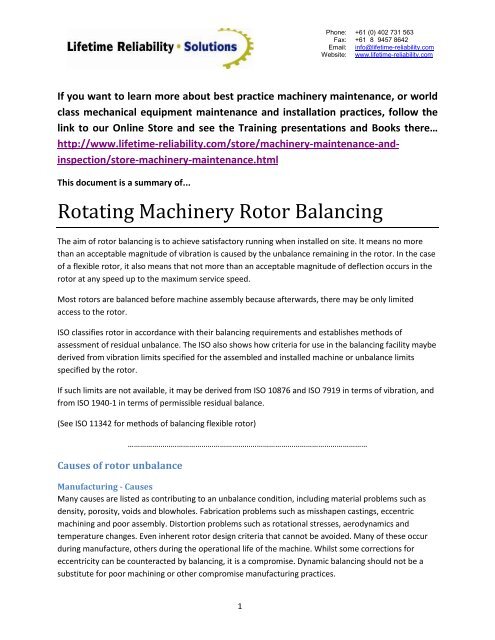
Phone:Fax:Email:Website:+61 (0) 402 731 563+61 (8) 9457 8642info@lifetime-reliability.comwww.lifetime-reliability.comIf you want to learn more about best practice machinery maintenance, or worldclass mechanical equipment maintenance and installation practices, follow thelink to our Online Store and see the Training presentations and Books there…http://www.lifetime-reliability.com/store/machinery-maintenance-andinspection/store-machinery-maintenance.htmlThis document is a summary <strong>of</strong>...<strong>Rotating</strong> <strong>Machinery</strong> <strong>Rotor</strong> <strong>Balancing</strong>The aim <strong>of</strong> rotor balancing is to achieve satisfactory running when installed on site. It means no morethan an acceptable magnitude <strong>of</strong> vibration is caused by the unbalance remaining in the rotor. In the case<strong>of</strong> a flexible rotor, it also means that not more than an acceptable magnitude <strong>of</strong> deflection occurs in therotor at any speed up to the maximum service speed.Most rotors are balanced before machine assembly because afterwards, there may be only limitedaccess to the rotor.ISO classifies rotor in accordance with their balancing requirements and establishes methods <strong>of</strong>assessment <strong>of</strong> residual unbalance. The ISO also shows how criteria for use in the balancing facility maybederived from vibration limits specified for the assembled and installed machine or unbalance limitsspecified by the rotor.If such limits are not available, it may be derived from ISO 10876 and ISO 7919 in terms <strong>of</strong> vibration, andfrom ISO 1940-1 in terms <strong>of</strong> permissible residual balance.(See ISO 11342 for methods <strong>of</strong> balancing flexible rotor)Causes <strong>of</strong> rotor unbalance………………………………………………………………………………………………………Manufacturing - CausesMany causes are listed as contributing to an unbalance condition, including material problems such asdensity, porosity, voids and blowholes. Fabrication problems such as misshapen castings, eccentricmachining and poor assembly. Distortion problems such as rotational stresses, aerodynamics andtemperature changes. Even inherent rotor design criteria that cannot be avoided. Many <strong>of</strong> these occurduring manufacture, others during the operational life <strong>of</strong> the machine. Whilst some corrections foreccentricity can be counteracted by balancing, it is a compromise. Dynamic balancing should not be asubstitute for poor machining or other compromise manufacturing practices.1
Phone:Fax:Email:Website:+61 (0) 402 731 563+61 (8) 9457 8642info@lifetime-reliability.comwww.lifetime-reliability.comIn the manufacturing process, if proper care is taken to ensure that castings are sound and machining isconcentric, then it follows that the two axis will coincide and the assembled rotor will be in a state <strong>of</strong>balance (Lyons, 1998).Assembly - CausesAs previously stated, there are many reasons why unbalance occurs when a rotor is being fabricated.Principle among these is a stack up <strong>of</strong> tolerances. When a well-balanced shaft and a well-balanced rotorare united, the necessary assembly tolerances can permit radial displacement, which will produce an out<strong>of</strong> balance condition. The addition <strong>of</strong> keys and keyways adds to the problem. Although an ISO standarddoes exist for Shaft and Fitment Key Conventions (refer to ISO 8821), in practice, differentmanufacturers follow their own procedures. Some use a full key, some a half key and some no key atall. Thus, when a unit is assembled and the permanent key is added, unbalance will <strong>of</strong>ten be the result.The modern balancing tolerances specified by ISO, API, ANSI and others make it imperative that theconventions listed in the ISO standard be followed. Failure to do so will mean that the low-level balancetolerances specified in these standards will be impossible to achieve (Lyons, 1998).Installed Machines - CausesWhen a rotor has been in service for some time, various other factors can contribute to the balancecondition. These include corrosion, wear, distortion, and deposit build up. Deposits can also break <strong>of</strong>funevenly, which can lead to severe unbalance. This particularly applies to fans, blowers, compressorsand other rotating devices handling process variables. Routine inspection and cleaning can minimize theeffect, but eventually the machines will have to be removed from service for balancing.Large unbalances will <strong>of</strong> course require large weight corrections and unless care is taken, this can have adetrimental effect on the integrity <strong>of</strong> the rotor. Concentrating a weight adjustment (whether adding ortaking away) at a given point can weaken the rotor. For example paper rolls are fabricated from tubingand large additions or removal <strong>of</strong> weight can affect the strength <strong>of</strong> the walls <strong>of</strong> the roll. This may cause it2
Phone:Fax:Email:Website:+61 (0) 402 731 563+61 (8) 9457 8642info@lifetime-reliability.comwww.lifetime-reliability.comto deflect when spinning at operating speed and thus induce harmful vibrations on the bearings andpaper machine frame (Lyons, 1998).Other CausesAnother cause <strong>of</strong> unbalance that is not readily apparent, is the difference between types <strong>of</strong> rotors.There are two distinct types - rigid and flexible.If a rotor is operating within 70% - 75% <strong>of</strong> its critical speed (the speed at which resonance occurs, i.e. itsnatural frequency) it can be considered to be a flexible rotor. If it is operating below that speed it isconsidered rigid.A rigid rotor can be balanced at the two end planes and will stay in balance when in service. A flexiblerotor will require multi-plane balancing. If a rotor is balanced on a low speed balancing machineassuming it is rigid and then in service becomes flexible, then unbalance and thus high vibration, will bethe result.Typical machines, which fit this category, include steam and gas turbines, multistage centrifugal pumps,compressors and paper rolls. In the paper industry particularly, use <strong>of</strong> roll balancing methods that weresatisfactory when paper machines were running at low speed, are now inadequate. As older machinesspeed up and new high-speed machines are installed, precision roll balancing is mandatory. Failure to doso will result in roll deflections which can effect product quality and even cause structural damage. Themethod used to produce a balanced roll with minimum deflection or whip over its operating speed rangeis a multi-plane technique. The choice <strong>of</strong> the balancing planes along the length <strong>of</strong> the roll is vital (Lyons,1998).<strong>Balancing</strong> rotating partsMethods to check for static balancingThere are several methods <strong>of</strong> testing the standing or static balance <strong>of</strong> a rotating part. A simple methodthat is sometimes used for flywheels, etc., is illustrated by the diagram, Fig. 1. An accurate shaft isinserted through the bore <strong>of</strong> the finished wheel, which is then mounted on carefully leveled “parallels” A.If the wheel is in an unbalanced state, it will turn until the heavy side is downward. When it will stand inany position as the result <strong>of</strong> counterbalancing and reducing the heavy portions, it is said to be in standingor static balance.3
Phone:Fax:Email:Website:+61 (0) 402 731 563+61 (8) 9457 8642info@lifetime-reliability.comwww.lifetime-reliability.comAnother test which is used for disk-shaped parts is shown in Fig. 2 below. The disk D is mounted on avertical arbor attached to an adjustable cross-slide B. The latter is carried by a table C, which issupported by a knife-edged bearing. A pendulum having an adjust-able screw-weight W at the lower endis suspended from cross-slide B. To test the static balance <strong>of</strong> disk D, slide B is adjusted until pointer E <strong>of</strong>the pendulum coincides with the center <strong>of</strong> a stationary scale F. Disk D is then turned halfway aroundwithout moving the slide, and if the indicator remains stationary, it shows that the disk is in balance forthis particular position. The test is then repeated for ten or twelve other positions, and the heavy sidesare reduced, usually by drilling out the required amount <strong>of</strong> metal. Several other devices for testing staticbalance are designed on this same principle.Methods to check for dynamic balancingA cylindrical maybe in perfect static balance and not be in a balanced state when rotating at high speed.If the part is in the form <strong>of</strong> a thin disk, static balancing, if carefully done, maybe accurate at high speeds.However if the rotating part is long in relative to its diameter, and the unbalanced portion are atopposite ends or in different planes. The balancing must be done so as to counter act the centrifugal4
Phone:Fax:Email:Website:+61 (0) 402 731 563+61 (8) 9457 8642info@lifetime-reliability.comwww.lifetime-reliability.comforce <strong>of</strong> these heavy parts when they are rotating rapidly. This process is known as a running balance ordynamicbalancing.To illustrate, if a heavy section is located at H (Fig. 3), and another correspondingly heavy section at H 1 ,one may exactly counterbalance the other when the cylinder is stationary, and this static balance may besufficient for a part rigidly mounted and rotating at a comparatively slow speed; but when the speed isvery high, as in turbine rotors, etc., the heavy masses H and H 1 , being in different planes, are in anunbalanced state owing to the effect <strong>of</strong> centrifugal force, which results in excessive strains and injuriousvibrations. Theoretically, to obtain a perfect running balance, the exact positions <strong>of</strong> the heavy sectionsshould be located and the balancing effected either by reducing their weight or by addingcounterweights opposite each section and in the same plane at the proper radius; but if the rotating partis rigidly mounted on a stiff shaft, a running balance that is sufficiently accurate for practical purposescan be obtained by means <strong>of</strong> comparatively few counterbalancing weights located with reference to theunbalanced parts.<strong>Balancing</strong> machineA balance machine is used to detect the amount and location <strong>of</strong> the unbalanced masses on a rotor. It is adevice that spins the rotor a set <strong>of</strong> spring mounted bearings. With the s<strong>of</strong>t bearings, any imbalance willcause the rotor to move about as it spins. The machine measures the phase angle and amplitude <strong>of</strong> themovement, and computes the unbalance which must be present to cause the motion. Appropriatecorrections can then be made by the operator (Bloch & Singh, 2008).Basic methods <strong>of</strong> balancing<strong>Rotor</strong> can be balanced by aligning the rotor mass with the bearing centers (Norfield, 2006).5
Phone:Fax:Email:Website:+61 (0) 402 731 563+61 (8) 9457 8642info@lifetime-reliability.comwww.lifetime-reliability.comThe rotor is symmetrical except for the unbalanced m at radius r:U = m*r = M*eU = M*e so e = U/M = m*r/MThe unbalance mass m times its radius r equals U <strong>Rotor</strong> unbalance. Divide this by rotor mass and we get‘e’, which is a measure <strong>of</strong> unbalance that is independent <strong>of</strong> rotor mass. It is called mass eccentricity, orspecific unbalance. It is the displacement <strong>of</strong> the mass center from the bearing center.Mass axisWhen we force an object to spin about a defined bearing axis there is a fixed reference for the rotationaxis (bearing axis). If the mass is not evenly distributed about that fixed axis then we have unbalance.The axis about which the mass is evenly distributed is defined as the mass axis.6
Phone:Fax:Email:Website:+61 (0) 402 731 563+61 (8) 9457 8642info@lifetime-reliability.comwww.lifetime-reliability.comThe mass eccentricity ‘e’ is the measure <strong>of</strong> the unbalance in terms <strong>of</strong> the displacement <strong>of</strong> the mass axisand the bearing axis. Units are linear – inches or mm. The eccentricity multiplied by the rotor mass givesthe unbalance. The units are the combination <strong>of</strong> mass and eccentricity – ounce.inches or gram.millimeter.<strong>Balancing</strong> definedThe rotor wants to spin about its mass axis but we want it to spin about the bearing axis. The results areforce on the bearings, vibration <strong>of</strong> the bearings or a combination <strong>of</strong> both (Norfield, 2006).It is defined as a procedure by which the mass distribution <strong>of</strong> a rotor is checked and, if necessary,adjusted in order to ensure that the vibration <strong>of</strong> the journals and/or forces on the bearings at afrequency corresponding to service speed are within specified limits (ISO 1925).For a given unbalance condition the vibration is inversely related, and force on the bearings is directlyrelated, to the bearing stiffness (ISO 1925). Unbalance is not shown by the external appearance but bythe vibration or force it generates. A rotor may have a hole drilled in the outside. That may be there tocorrect the unbalance rather than being the cause <strong>of</strong> the unbalance (Norfield, 2006).The balancing machine is the meter for unbalance, and makes real measurements <strong>of</strong> the rotor condition.<strong>Rotor</strong> rigidityThere are a number <strong>of</strong> classifications <strong>of</strong> rotors, depending on flexibility, operating speed, and otherfactors (ISO 5243).Class 1 is rigid rotors – this covers 90% <strong>of</strong> applicationClass 2 is rotors that are not rigid or that have special characteristics <strong>of</strong> mass distribution but that can bebalanced using a modified balancing technique (choice <strong>of</strong> correction planes is the key here).Class 3 and 4 are flexible rotorsNote some motors need to be balanced at specific speeds, at two speeds or even when hot. Thermaleffect can cause distortion that in turn causes unbalance, which can cause more distortion.Static unbalanceIt is defined as acting through the mass center <strong>of</strong> the rotor and by definition can be corrected at a singlelocation by adding or removing material in line with the center <strong>of</strong> mass. Implicit in the definition is thatthe mass axis remains parallel to the bearing axis. Static unbalance can be detected without spinning therotor (Norfield, 2006).7
Phone:Fax:Email:Website:+61 (0) 402 731 563+61 (8) 9457 8642info@lifetime-reliability.comwww.lifetime-reliability.com<strong>Balancing</strong> on knife edges can correct for static unbalance but without any qualitative measurement <strong>of</strong>the remaining amount <strong>of</strong> unbalance – depends on friction, wind, shaft diameter, rotor mass, etc. Thisdoes not confront the basic definition <strong>of</strong> checking the unbalance against a known standard. Most singleplane balancing is done on rotating (centrifugal) balancing machines. Non-rotating (gravitational)balancers are used for high volume production <strong>of</strong> rotors with coarse tolerance. (These measure thecalibrated deflection <strong>of</strong> a spring or the <strong>of</strong>fset force using two load cells.)Couple unbalanceCouple unbalance is what you get when you balance on knife edges and don’t correct the real source <strong>of</strong>unbalance. The image below shows a rotor that had an unbalance at one end and was static balancedwith correction <strong>of</strong> the end opposite the unbalance. Result is that it looks good on knife edges but willshake like crazy as soon as it spins. Note that the mass axis crosses the geometric axis at the center sothere is no static unbalance.Dynamic unbalance, balancing in different planes balancing machine, correction procedure(please refer to Norfield for more detail)Limits and toleranceThere are International standards that we can use as guidelines for balance tolerances but they are bynature very general. Relying just on one <strong>of</strong> these standards can give you a tolerance that is quite a way<strong>of</strong>f from the optimum.Tolerance needs to be most cost effective to perform without premature bearing failure or excessivevibration. The proper way to determine the ideal balance tolerance is to take a batch <strong>of</strong> wellmanufacturedrotors, balance them as low as possible and then run them and progressively addunbalance until the performance is just acceptable. Now the unbalance can be measured and a limit8
Phone:Fax:Email:Website:+61 (0) 402 731 563+61 (8) 9457 8642info@lifetime-reliability.comwww.lifetime-reliability.comdetermined that gives good results without being too tight. These rotors should also be checked forvibration signature under operating conditions to classify what other vibrations may affect performance.One other variable needs to be considered in the production process – the variations that occur afterbalancing due to assembly and stack up tolerances. Armatures are balanced and then bearings areadded. The motor is fitted with a drive pulley or a flywheel that has a loose fitting tolerance. The result ishigh vibration on a percentage <strong>of</strong> the assemblies.StandardsISO 1940 is based on the measurement <strong>of</strong> machinery vibration velocity The ANSI spec is identical butprinted by American National Standards Institute. The API specification is written around pumprequirements in the Petro-Chemical Industries and classifies unbalance levels as a function <strong>of</strong> rotor massand operating speed (Norfield, 2006).ISO 1940 is famous for its classification <strong>of</strong> vibration in terms <strong>of</strong> G codes although many people don’tknow what they mean it is easy to figure out that G2.5 is a tighter tolerance than G6.3. Notice thechoice <strong>of</strong> words here, tighter not necessarily better. G2.5 means a vibration velocity <strong>of</strong> 2.5 mm/s underspecified conditions. Unfortunately, it is the theoretical value assuming the rotor was spinning in freespace so it does not relate to actual operating conditions.ISO 1940 uses a set <strong>of</strong> criteria to classify the acceptable vibration grade – a low speed marine diesel has acoarse grade while a high speed grinding spindle has a very tight grade. The tightest grades requirebalancing a rotor in its own bearings and under service conditions.Example <strong>of</strong> getting the numbersU per = balance toleranceG number can be obtained from the table below (ISO 1940):9
Phone:Fax:Email:Website:+61 (0) 402 731 563+61 (8) 9457 8642info@lifetime-reliability.comwww.lifetime-reliability.comBalance quality grades for various groups <strong>of</strong> representative rigid motors10
Phone:Fax:Email:Website:+61 (0) 402 731 563+61 (8) 9457 8642info@lifetime-reliability.comwww.lifetime-reliability.comAPI 610API 610 is based on the following formula (using SI units):T = 6350W/NW = rotor weight in kgn = speed in RPMT = tolerance in kgNote the formula does not work 100%. For high speed pumps, tolerance can get ridiculously tight. (Whenthe tolerance is below 20% <strong>of</strong> the diameter tolerance <strong>of</strong> the bore it can be classed as ridiculous)One very specific problem with the API specification is that it does not make any allowance for balancetooling error and bore clearance on the arbor. The idea is to balance to almost‘zero’ on the balancer inorder to allow for assembly errors. The result is that a high vibration pump may be stripped down,and the impeller balance checked only to find high unbalance (actually due to non-repeatability <strong>of</strong>mounting). After rebalancing and reassembly there may still be high unbalance or, conversely, it may beOK. A secondary result may be that the operator loses confidence in the balancing machine and tooling.(For rotors) Lastly, during the shop test <strong>of</strong> the machine, assembled with the balanced rotor, operating atits maximum continuous speed or at any other speed within the specific operating speed range, the peakto peak amplitude <strong>of</strong> unfiltered vibration in any plane, measured on the shaft adjacent and relative toeach radial bearing, may not exceed the following value (based on SI) or 2.0 mil (50 µm), whichever isless (Bloch & Singh, 2008):A = amplitude <strong>of</strong> unfiltered vibration, mil (µm) peak to peakN = maximum continuous speed, r/min (RPM)Practical example:If we have a rotor mass <strong>of</strong> 235 kg, 420 mm in radius, and running at speed <strong>of</strong> 3000 RPM, supported by 2bearings.Permissible balance based on ISO 1940 chart or equation for G1, e will be read as 3 g.mm/kg, which giveus 705 g.mm (after times it by the rotor mass to obtain U).Based on API 610, 6350xMass/speed = 497 g.mmPermissible unbalance mass (times by the radius) will be 1.6 g.11
Phone:Fax:Email:Website:+61 (0) 402 731 563+61 (8) 9457 8642info@lifetime-reliability.comwww.lifetime-reliability.comBased on API 610, 1.2 g.(ISO definition suggests verifying balancing machine operation to be done once a year or every 3 monthsfor aero applications.)Allocation <strong>of</strong> Uper to correction planes (IRD balancing, 2009)Correction plane: any plane perpendicular to the shaft axis where balance corrections are made.To calculate tolerance U at different planes, please refer to methods used in ISO 1940 -1.U per must be allocated to the balancing correction planes used based on rotor dimension andconfiguration.For rotor balanced in a single correction plane, all <strong>of</strong> the U per applies to that correction plane.For rotor balanced in two correction planes, U per must be allocated to each correction based on rotorconfiguration and dimensions.Symmetrical rotors (IRD balancing, 2009)Rules for symmetrical rotors:Correction planes are between bearings.Distance “b” is greater than 1/3 “d”.Correction planes are equidistant from the center <strong>of</strong> gravity.U per left = U per Right = U per /212
Phone:Fax:Email:Website:+61 (0) 402 731 563+61 (8) 9457 8642info@lifetime-reliability.comwww.lifetime-reliability.comWhen correction planes are not equidistant from the center <strong>of</strong> gravity, thenU per left = U per (h R /b)U per right = U per (h L /b)Note U per left or U per right should not be less than 30% or more than 70% U per . If they are, the use rulesfor narrow rotors.<strong>Rotor</strong>s with outbound correction planes (IRD balancing, 2009)Both correction planes are outboard <strong>of</strong> the bearings.b > dAdjust U per by ratio <strong>of</strong> d/b (reduces U per )U per = U per (d/b)U per = Adjusted valueWhen correction planes are not equidistant from the center <strong>of</strong> gravity, thenU per left = U per (h R /b)U per right = U per (h L /b)13
Phone:Fax:Email:Website:+61 (0) 402 731 563+61 (8) 9457 8642info@lifetime-reliability.comwww.lifetime-reliability.comOverhung and narrow rotors (IRD balancing, 2009)Overhung rotorsNarrow rotorsRules for overhung and narrow rotors”Distance between correction planes is less than 1/3 the distance between bearings. b < 0.33 dAssumes equal permissible dynamic bearing loadsCouple corrections are made 180® apart in their respective planesThe plane for static corrections may be a third plane or either <strong>of</strong> the planes used for couplecorrections.Allocate U per as static and couple residual unbalance as follows:14
Phone:Fax:Email:Website:+61 (0) 402 731 563+61 (8) 9457 8642info@lifetime-reliability.comwww.lifetime-reliability.comU per static = U per /2*d/2cU per couple = U per /2*3d/4bComparison <strong>of</strong> standardsThe report compares three standards: ISO (G6.3, G2.5, G1.0), MIL-STD and API. The conclusion is that APIstandard demands a low residual unbalance level and with a smaller unbalance force load on the rotor’sbearings. However the effort to achieve this result may not always be cost effective (IRD balancing, 2009).Bent shaftA shaft that is straight at room temperature may bend when running at full load, especially if there isan uneven heating effect. Excessive belt tension can bend a shaft (also it can cause rapid bearingfailure). Longer shafts will sag if they are not kept turning slowly. Other shaft problems can result frommachining errors. It is not uncommon for fork lift trucks to get <strong>of</strong>f course and the resulting impactdamage can be fatal to equipment (Norfield, 2006).A long slender rotor, such as a drive shaft, will bend at high speed. This is not a change <strong>of</strong> unbalance buta rotor deformation problem. The unbalance tolerance and unbalance correction locations have to beselected to ensure safe operation for the operating speed range.<strong>Balancing</strong> shaft and fitment key conventionIt is <strong>of</strong>ten impossible or economically unfeasible to balance rotors and fitments after they have beenassembled; they are, therefore, balanced separately. An appropriate balance tolerance is applied so that,when rotor end fitments are coupled together with the appropriate key, the assembly will meet therequired balance tolerance and vibration severity level. However, if a different key convention has beenused when balancing the shaft or rotor than the one used for balancing the fitment, it is quite likely thatthe assembly will have balancing errors exceeding the permissible residual unbalance (please refer to ISO8821 for balance methods).You can learn a lot more about rotating equipment health management with the 4-day <strong>Rotating</strong><strong>Machinery</strong> Maintenance and <strong>Reliability</strong> Training Course PowerPoint Presentation available to buy at the<strong>Lifetime</strong> <strong>Reliability</strong> Solutions online Web store.You can learn a lot more about rotating equipment vibration management with the 4-day Fundamentals<strong>of</strong> <strong>Machinery</strong> Vibration Measurement, Vibration Analysis and Vibration Control Training PPT PowerPointPresentation available to buy at the <strong>Lifetime</strong> <strong>Reliability</strong> Solutions online Web store.15