Amal ES_0_0_132 (IR) - Safety Systems UK Ltd
Amal ES_0_0_132 (IR) - Safety Systems UK Ltd
Amal ES_0_0_132 (IR) - Safety Systems UK Ltd

Create successful ePaper yourself
Turn your PDF publications into a flip-book with our unique Google optimized e-Paper software.
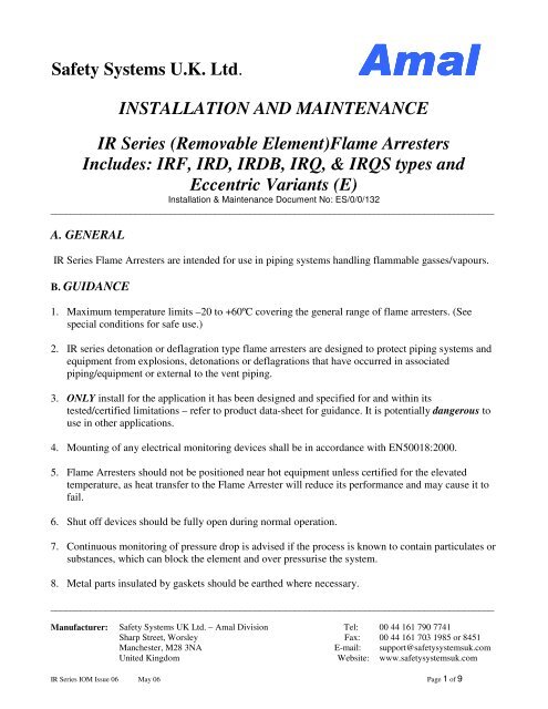
<strong>Safety</strong> <strong>Systems</strong> U.K. <strong>Ltd</strong>.<strong>Amal</strong>INSTALLATION AND MAINTENANCE<strong>IR</strong> Series (Removable Element)Flame ArrestersIncludes: <strong>IR</strong>F, <strong>IR</strong>D, <strong>IR</strong>DB, <strong>IR</strong>Q, & <strong>IR</strong>QS types andEccentric Variants (E)Installation & Maintenance Document No: <strong>ES</strong>/0/0/<strong>132</strong>_________________________________________________________________________________________A. GENERAL<strong>IR</strong> Series Flame Arresters are intended for use in piping systems handling flammable gasses/vapours.B. GUIDANCE1. Maximum temperature limits –20 to +60ºC covering the general range of flame arresters. (Seespecial conditions for safe use.)2. <strong>IR</strong> series detonation or deflagration type flame arresters are designed to protect piping systems andequipment from explosions, detonations or deflagrations that have occurred in associatedpiping/equipment or external to the vent piping.3. ONLY install for the application it has been designed and specified for and within itstested/certified limitations – refer to product data-sheet for guidance. It is potentially dangerous touse in other applications.4. Mounting of any electrical monitoring devices shall be in accordance with EN50018:2000.5. Flame Arresters should not be positioned near hot equipment unless certified for the elevatedtemperature, as heat transfer to the Flame Arrester will reduce its performance and may cause it tofail.6. Shut off devices should be fully open during normal operation.7. Continuous monitoring of pressure drop is advised if the process is known to contain particulates orsubstances, which can block the element and over pressurise the system.8. Metal parts insulated by gaskets should be earthed where necessary._________________________________________________________________________________________Manufacturer:<strong>Safety</strong> <strong>Systems</strong> <strong>UK</strong> <strong>Ltd</strong>. – <strong>Amal</strong> DivisionSharp Street, WorsleyManchester, M28 3NAUnited KingdomTel:Fax:E-mail:Website:00 44 161 790 774100 44 161 703 1985 or 8451support@safetysystemsuk.comwww.safetysystemsuk.com<strong>IR</strong> Series IOM Issue 06 May 06 Page 1 of 9
<strong>Safety</strong> <strong>Systems</strong> U.K. <strong>Ltd</strong>.<strong>Amal</strong>INSTALLATION AND MAINTENANCE<strong>IR</strong> Series (Removable Element)Flame ArrestersIncludes: <strong>IR</strong>F, <strong>IR</strong>D, <strong>IR</strong>DB, <strong>IR</strong>Q, & <strong>IR</strong>QS types andEccentric Variants (E)Installation & Maintenance Document No: <strong>ES</strong>/0/0/<strong>132</strong>_________________________________________________________________________________________9. Flame velocities and pressures of flammable mixtures can be enhanced by upstream turbulence,which can be caused by bends, valves or any change in section of the pipework. The Flame Arrestershould only be used for the process application; if the process conditions or the pipeworkconfiguration change, the Flame Arrester specification should be re-checked with the manufacturer.10. If the normal operating or atmospheric temperature can cause freezing within the flame arrester it isadvisable to provide trace heating to the flame arrester element and housings, if electrical this mustbe in accordance with EN500018:2000. It is important to ensure that the flame arrester unit isATEX certified for use at the elevated temperature of the process fluid, created by the externalheating source.11. Where a dedicated heating jacket (steam or hot fluids) is supplied as part of the flame arrester unit,the flame arrester will be denoted ‘J’ type e.g. <strong>IR</strong>QJ. In cases such as these the flame arrestershould be fitted with the heating fluid connection in a vertical attitude. The inlet connection shouldbe at the top of the housing and the outlet should be at the bottom of the housing to facilitatedrainage. Extra care should be taken to ensure that when the heating fluid pipes are removed formaintenance purposes, heat resisting hand protection is worn to protect the operator from anypotential burning.Monitor the temperature of the flame arrester unit to ensure that the process fluid does not riseabove its auto ignition temperature.C. INSTALLATION1. Remove all packaging from the flame arrester prior to installation, paying particular attention tothe inlet and outlet housing sections.2. Mount the flame arrester in the pipeline in the orientation it has been designed for. <strong>Amal</strong> <strong>IR</strong>DB,<strong>IR</strong>Q, <strong>IR</strong>QS (E) types are normally bi-directional and can be fitted either way round unless they aremade one directional by accessories fitted to the inlet or outlet housing sections only – in this case_________________________________________________________________________________________Manufacturer:<strong>Safety</strong> <strong>Systems</strong> <strong>UK</strong> <strong>Ltd</strong>. – <strong>Amal</strong> DivisionSharp Street, WorsleyManchester, M28 3NAUnited KingdomTel:Fax:E-mail:Website:00 44 161 790 774100 44 161 703 1985 or 8451support@safetysystemsuk.comwww.safetysystemsuk.com<strong>IR</strong> Series IOM Issue 06 May 06 Page 2 of 9
<strong>Safety</strong> <strong>Systems</strong> U.K. <strong>Ltd</strong>.<strong>Amal</strong>INSTALLATION AND MAINTENANCE<strong>IR</strong> Series (Removable Element)Flame ArrestersIncludes: <strong>IR</strong>F, <strong>IR</strong>D, <strong>IR</strong>DB, <strong>IR</strong>Q, & <strong>IR</strong>QS types andEccentric Variants (E)Installation & Maintenance Document No: <strong>ES</strong>/0/0/<strong>132</strong>_________________________________________________________________________________________a directional arrow is included showing the direction of normal flow. Types <strong>IR</strong>, <strong>IR</strong>F & <strong>IR</strong>D are onedirectional, in these cases a directional arrow is included.(i) Flanged connection – bolt to flanges of the same specification as those fitted to theflame arrester itself, with intermediate gaskets of a type appropriate to the serviceconditions. Uniformly tighten the bolting to ensure a good seal.(ii) Screwed connection (DN80 or 3” NPS and smaller) – fit to the correspondingmale/female threads. Sealing tape or sealant may be used to ensure a good seal.3. Ensure that any accessory nozzles are fitted with the necessary accessories or with plugs/blankingflanges as appropriate.4. When appropriate, it is recommended that a protective cage be installed to guard the flame arresteragainst accidental impact from vehicles or from heavy falling objects.D. MAINTENANC<strong>ES</strong>hould only be carried out by suitably qualified personnel.1. During service the element matrix may become blocked with particles and impurities from theatmosphere and/or process. If too severe the blockage will impair the free flow of gases/vapours. Insevere cases this can cause damage to equipment and the flame arrester itself. If excessive pressuredrop is experienced, or after any flashback or incident, immediate inspection should be made.Where a process is known to be dirty, a pressure limiting device, installed within theassociated pipeline is strongly recommended.2. A periodic maintenance schedule is recommended for the flame arrester, the frequency to be basedon operational experience and actual operating conditions, but at least annually.3. No special tools are required. Standard spanners, and lifting equipment for larger sizes of flamearrester, are required._________________________________________________________________________________________Manufacturer:<strong>Safety</strong> <strong>Systems</strong> <strong>UK</strong> <strong>Ltd</strong>. – <strong>Amal</strong> DivisionSharp Street, WorsleyManchester, M28 3NAUnited KingdomTel:Fax:E-mail:Website:00 44 161 790 774100 44 161 703 1985 or 8451support@safetysystemsuk.comwww.safetysystemsuk.com<strong>IR</strong> Series IOM Issue 06 May 06 Page 3 of 9
<strong>Safety</strong> <strong>Systems</strong> U.K. <strong>Ltd</strong>.<strong>Amal</strong>INSTALLATION AND MAINTENANCE<strong>IR</strong> Series (Removable Element)Flame ArrestersIncludes: <strong>IR</strong>F, <strong>IR</strong>D, <strong>IR</strong>DB, <strong>IR</strong>Q, & <strong>IR</strong>QS types andEccentric Variants (E)Installation & Maintenance Document No: <strong>ES</strong>/0/0/<strong>132</strong>_________________________________________________________________________________________4. <strong>IR</strong> series flame arresters are designed to allow inspection and maintenance in situ, however, thisshould only be done if it is safe to do so.NOTE: Potentially toxic substances may have been passing through the flame arrester. Alwayswear appropriate safety equipment, with eye protection, when working on or near Flame Arresters.If the flame arrester has a heating jacket it will be necessary to drain the flame arrester jacket, andin order to do this the heating fluid pipes will need to be disconnected; always ensure that heatresisting gloves are worn before this is done since hot fluid may spill from the connecting joints.5. Loosen the bolting around the central flanges containing the element assembly/assemblies.6. Separate the central flanges, using any jacking bolts that may be fitted to the flame arrester or otherappropriate means, by an amount sufficient to allow removal of the gaskets and elementassembly/assemblies. Note that where unsupported backing flanges have been used this may not bepossible and the complete flame arrester may have to be taken from the pipeline.7. Remove sufficient bolting to allow the gaskets and element assembly to be removed, or, where aswing out element assembly is fitted, for it to be swung out for inspection.8. Remove the element(s), using lifting equipment where appropriate, and examine both surfaces. DONOT insert any probes into the element.9. If the element matrix is visually damaged or corroded it must be replaced before the flame arresteris returned into service. If cleaning is required see Section E before re-fitting.10. Check the sealing face of the housing is clean and free from particles that may affect the sealing ofthe element.NOTE: Any gaps between the housing and gaskets/element may provide a flame path around theflame arrester element and are therefore DANGEROUS._________________________________________________________________________________________Manufacturer:<strong>Safety</strong> <strong>Systems</strong> <strong>UK</strong> <strong>Ltd</strong>. – <strong>Amal</strong> DivisionSharp Street, WorsleyManchester, M28 3NAUnited KingdomTel:Fax:E-mail:Website:00 44 161 790 774100 44 161 703 1985 or 8451support@safetysystemsuk.comwww.safetysystemsuk.com<strong>IR</strong> Series IOM Issue 06 May 06 Page 4 of 9
<strong>Safety</strong> <strong>Systems</strong> U.K. <strong>Ltd</strong>.<strong>Amal</strong>INSTALLATION AND MAINTENANCE<strong>IR</strong> Series (Removable Element)Flame ArrestersIncludes: <strong>IR</strong>F, <strong>IR</strong>D, <strong>IR</strong>DB, <strong>IR</strong>Q, & <strong>IR</strong>QS types andEccentric Variants (E)Installation & Maintenance Document No: <strong>ES</strong>/0/0/<strong>132</strong>_________________________________________________________________________________________11. Fit new gaskets of the same specification and re-fit the element(s) ensuring that it is centrallylocated – there may be locating collars fitted to some of the bolts to assist in this.12. Where more than one element is fitted ensure that all lifting eyes are in complete alignment.13. Replace the bolting and tighten to the appropriate torque.14. After any external fire in the locality of the Flame Arrester, it is recommended that the equipmentbe examined for damage, with particular attention paid to the joint gaskets, replacing them ifnecessary. Also check the tightness of the flange bolting, and retighten if necessary.E. CLEANING THE ELEMENT ASSEMBLY1. DO NOT attempt to remove the element matrix from its cage/casing.2. DO NOT allow the element assembly to become severely blocked.3. DO NOT clean by inserting probes into the cell structure.4. DO NOT use excessively corrosive materials (e.g. hydrochloric acid) to clean the element.5. High-pressure water jets ARE NOT recommended.6. The following ARE recommended: detergents, solvents, compressed air, steam, or ultrasonic. Theactual cleaning method will depend on the nature of the substance causing the blockage.7. If the element is DAMAGED during cleaning a NEW element assembly should be fitted. If indoubt refer to <strong>Amal</strong>, or you’re nearest representative, for advice._________________________________________________________________________________________Manufacturer:<strong>Safety</strong> <strong>Systems</strong> <strong>UK</strong> <strong>Ltd</strong>. – <strong>Amal</strong> DivisionSharp Street, WorsleyManchester, M28 3NAUnited KingdomTel:Fax:E-mail:Website:00 44 161 790 774100 44 161 703 1985 or 8451support@safetysystemsuk.comwww.safetysystemsuk.com<strong>IR</strong> Series IOM Issue 06 May 06 Page 5 of 9
<strong>Safety</strong> <strong>Systems</strong> U.K. <strong>Ltd</strong>.<strong>Amal</strong>INSTALLATION AND MAINTENANCE<strong>IR</strong> Series (Removable Element)Flame ArrestersIncludes: <strong>IR</strong>F, <strong>IR</strong>D, <strong>IR</strong>DB, <strong>IR</strong>Q, & <strong>IR</strong>QS types andEccentric Variants (E)Installation & Maintenance Document No: <strong>ES</strong>/0/0/<strong>132</strong>_________________________________________________________________________________________F. SPARE PARTSUnder normal conditions only the element assembly and gaskets should need replacing. It isrecommended that for every three-flame arresters of a given type and size, at any one site, at least onespare element assembly is available at all times. One set of gaskets for each flame arrester assemblyshould also be available.When requesting spare elements the full type code, part number, and serial number MUST be quoted –fitting the incorrect element is potentially DANGEROUS. See the flame arrester label and/or associateddetailed spare parts list for details.G. AFTER SAL<strong>ES</strong> SERVICEAfter sales service is available through the <strong>Safety</strong> <strong>Systems</strong> <strong>UK</strong> <strong>Ltd</strong>. head office in the United Kingdom,or through our worldwide network of regional offices and agents.H. MARKING on the FLAME ARR<strong>ES</strong>TER (CE PLATE)_________________________________________________________________________________________Manufacturer:<strong>Safety</strong> <strong>Systems</strong> <strong>UK</strong> <strong>Ltd</strong>. – <strong>Amal</strong> DivisionSharp Street, WorsleyManchester, M28 3NAUnited KingdomTel:Fax:E-mail:Website:00 44 161 790 774100 44 161 703 1985 or 8451support@safetysystemsuk.comwww.safetysystemsuk.com<strong>IR</strong> Series IOM Issue 06 May 06 Page 6 of 9
<strong>Safety</strong> <strong>Systems</strong> U.K. <strong>Ltd</strong>.<strong>Amal</strong>INSTALLATION AND MAINTENANCE<strong>IR</strong> Series (Removable Element)Flame ArrestersIncludes: <strong>IR</strong>F, <strong>IR</strong>D, <strong>IR</strong>DB, <strong>IR</strong>Q, & <strong>IR</strong>QS types andEccentric Variants (E)Installation & Maintenance Document No: <strong>ES</strong>/0/0/<strong>132</strong>_________________________________________________________________________________________I. MARKING on the FLAME ARR<strong>ES</strong>TER (NAMEPLATE)_________________________________________________________________________________________Manufacturer:<strong>Safety</strong> <strong>Systems</strong> <strong>UK</strong> <strong>Ltd</strong>. – <strong>Amal</strong> DivisionSharp Street, WorsleyManchester, M28 3NAUnited KingdomTel:Fax:E-mail:Website:00 44 161 790 774100 44 161 703 1985 or 8451support@safetysystemsuk.comwww.safetysystemsuk.com<strong>IR</strong> Series IOM Issue 06 May 06 Page 7 of 9
<strong>Safety</strong> <strong>Systems</strong> U.K. <strong>Ltd</strong>.<strong>Amal</strong>INSTALLATION AND MAINTENANCE<strong>IR</strong> Series (Removable Element)Flame ArrestersIncludes: <strong>IR</strong>F, <strong>IR</strong>D, <strong>IR</strong>DB, <strong>IR</strong>Q, & <strong>IR</strong>QS types andEccentric Variants (E)Installation & Maintenance Document No: <strong>ES</strong>/0/0/<strong>132</strong>_________________________________________________________________________________________J. SPECIAL CONDITIONS for SAFE USE. – manufacturing is intended as follows:Flame Arrester Matrix for ATEX approval covering Certificates INERIS03ATEX0075X with Additions /01, /02 and /03Type Connection Gas group Size range Short Det. Deflag Max. temp. Max temp Elementburn deflagration unstabledetonation<strong>IR</strong> (E) Flanged IIA DN12/450 Yes N/A Yes -20 / +60ºC N/A 1 x 0.8mm<strong>IR</strong> (E) Flanged IIB1/IIB3 DN12/450 Yes N/A Yes -20 / +60ºC N/A 1 x 0.8/0.6mm<strong>IR</strong>F, (E) Flanged IIA DN12/450 Yes N/A Yes -20 / +60ºC N/A 1 x 0.8mm<strong>IR</strong>F, (E) Flanged IIB1/IIB3 DN12/450 Yes N/A Yes -20 / +60ºC N/A 1 x 0.8/0.6mm<strong>IR</strong>E Flanged IIA DN40/200 Yes N/A Yes -20 / +60ºC N/A 1 x 0.6mm<strong>IR</strong>, <strong>IR</strong>F, (E) Flanged IIA DN12/450 No N/A Yes -20 / +165ºC N/A 1 x 0.6mm<strong>IR</strong>, <strong>IR</strong>F, (E) Flanged IIB1/IIB3 DN12/450 No N/A Yes -20 / +165ºC N/A 1 x 0.38mm<strong>IR</strong>, <strong>IR</strong>F, (E) Flanged IIB DN12/400 Yes N/A Yes -20 / +60º N/A 1 x 0.45mm<strong>IR</strong>, <strong>IR</strong>F (E) Flanged IIC DN12/150 Yes N/A Yes -20 / +60ºC N/A 1 x 0.15mm<strong>IR</strong>, <strong>IR</strong>F, (E) Flanged IIB DN12/100 No N/A Yes -20 / +165ºC N/A 1 x 0.3mm<strong>IR</strong>, <strong>IR</strong>F (E) Flanged IIC DN12/150 No N/A Yes -20 / +165ºC N/A 1 x 0.15mm<strong>IR</strong>, <strong>IR</strong>Q Flanged IIB3 DN200 No N/A Yes -20 / +260º N/A 1 x 0.38mm<strong>IR</strong>Q, <strong>IR</strong>QS, (E) Flanged IIA DN12/450 Yes N/A Yes -20 / +60ºC N/A 1 x 0.8mm<strong>IR</strong>Q, <strong>IR</strong>QS, (E) Flanged IIB1/IIB3 DN12/450 Yes N/A Yes -20 / +60ºC N/A 1 x 0.8/0.6mm<strong>IR</strong>Q, <strong>IR</strong>QS, (E) Flanged IIA DN12/450 No N/A Yes -20 / +165ºC N/A 1 x 0.6mm<strong>IR</strong>Q, <strong>IR</strong>QS, (E) Flanged IIB1/IIB3 DN12/450 No N/A Yes -20 / +165ºC N/A 1 x 0.38mm<strong>IR</strong>Q, <strong>IR</strong>QS, (E) Flanged IIB DN12/400 Yes N/A Yes -20 / +60ºC N/A 1 x 0.45mm<strong>IR</strong>Q, <strong>IR</strong>QS, (E) Flanged IIC DN12/150 Yes N/A Yes -20 / +60ºC N/A 1 x 0.15mm<strong>IR</strong>Q, <strong>IR</strong>QS, (E) Flanged IIB DN12/100 No N/A Yes -20 / +165ºC N/A 1 x 0.3mm<strong>IR</strong>Q, <strong>IR</strong>QS, (E) Flanged IIC DN12/100 No N/A Yes -20 / +165ºC N/A 1 x 0.15mm_________________________________________________________________________________________Manufacturer:<strong>Safety</strong> <strong>Systems</strong> <strong>UK</strong> <strong>Ltd</strong>. – <strong>Amal</strong> DivisionSharp Street, WorsleyManchester, M28 3NAUnited KingdomTel:Fax:E-mail:Website:00 44 161 790 774100 44 161 703 1985 or 8451support@safetysystemsuk.comwww.safetysystemsuk.com<strong>IR</strong> Series IOM Issue 06 May 06 Page 8 of 9
<strong>Safety</strong> <strong>Systems</strong> U.K. <strong>Ltd</strong>.<strong>Amal</strong>INSTALLATION AND MAINTENANCE<strong>IR</strong> Series (Removable Element)Flame ArrestersIncludes: <strong>IR</strong>F, <strong>IR</strong>D, <strong>IR</strong>DB, <strong>IR</strong>Q, & <strong>IR</strong>QS types andEccentric Variants (E)Installation & Maintenance Document No: <strong>ES</strong>/0/0/<strong>132</strong>_________________________________________________________________________________________Type Connections Gas group Size range Short Det. Deflag. Max. temp. Max temp Elementburn deflagration unstabledetonation<strong>IR</strong>D, <strong>IR</strong>DB, (E) Flanged IIA DN12/200 Yes Yes N/A N/A -20 / +60ºC 1 x 0.6/0.45mm<strong>IR</strong>D, <strong>IR</strong>DB, (E) Flanged IIA DN250/450 Yes Yes N/A N/A -20 / +60ºC 2 x 0.45mm<strong>IR</strong>D, <strong>IR</strong>DB, (E) Flanged IIA DN12/200 No Yes N/A N/A -20 / +165ºC 1 x 0.45mm<strong>IR</strong>D, <strong>IR</strong>DB, (E) Flanged IIA DN250/450 No Yes N/A N/A -20 / +165ºC 2 x 0.45mm<strong>IR</strong>D, <strong>IR</strong>DB, (E) Flanged IIB1/IIB3 DN12/150 Yes Yes N/A N/A -20 / +60ºC 1 x 0.45/0.38mm<strong>IR</strong>D, <strong>IR</strong>DB, (E) Flanged IIB1/IIB3 DN200/400 Yes Yes N/A N/A -20 / +60ºC 2x0.45/3 x0.38mm<strong>IR</strong>D, <strong>IR</strong>DB, (E) Flanged IIB1/IIB3 DN12/150 No Yes N/A N/A -20 / +165ºC 1 x 0.38mm<strong>IR</strong>D, <strong>IR</strong>DB, (E) Flanged IIB1/IIB3 DN200/400 No Yes N/A N/A -20 / +165ºC 3 x 0.38mm<strong>IR</strong>D, <strong>IR</strong>DB, (E) Flanged IIB DN12/150 Yes Yes N/A N/A -20 / +60ºC 1 x 0.3mm<strong>IR</strong>D, <strong>IR</strong>DB, (E) Flanged IIB DN12/100 No Yes N/A N/A -20 / +165ºC 1 x 0.3mm<strong>IR</strong>D, <strong>IR</strong>DB, (E) Flanged IIC DN12/150 Yes Yes N/A N/A -20 / +60ºC 1 x 0.15/2x0.15mm<strong>IR</strong>D, <strong>IR</strong>DB, (E) Flanged IIC DN100 No Yes N/A N/A -20 / +165ºC 2 x 0.15mm<strong>IR</strong>D, <strong>IR</strong>DB, (E) Flanged IIC DN12/80 No Yes N/A N/A -20 / +165ºC 1 x 0.15mm_________________________________________________________________________________________Manufacturer:<strong>Safety</strong> <strong>Systems</strong> <strong>UK</strong> <strong>Ltd</strong>. – <strong>Amal</strong> DivisionSharp Street, WorsleyManchester, M28 3NAUnited KingdomTel:Fax:E-mail:Website:00 44 161 790 774100 44 161 703 1985 or 8451support@safetysystemsuk.comwww.safetysystemsuk.com<strong>IR</strong> Series IOM Issue 06 May 06 Page 9 of 9


![ES139[IOM Fig 785 Marvac Emergency Relief Vent]](https://img.yumpu.com/43585698/1/190x245/es139iom-fig-785-marvac-emergency-relief-vent.jpg?quality=85)