Barcode Positioning System BE-90 PB for the ... - TR Electronic
Barcode Positioning System BE-90 PB for the ... - TR Electronic
Barcode Positioning System BE-90 PB for the ... - TR Electronic

Create successful ePaper yourself
Turn your PDF publications into a flip-book with our unique Google optimized e-Paper software.
Technical Description <strong>BE</strong>-<strong>90</strong> P<strong>BE</strong>LEC<strong>TR</strong>ONIC GmbH2 Safety notices2.1 Safety standardsThe barcode positioning system <strong>BE</strong>-<strong>90</strong> <strong>PB</strong> and <strong>the</strong> modular hoods with integrated connectors<strong>BE</strong>-<strong>90</strong> CU <strong>PB</strong>3/<strong>BE</strong>-<strong>90</strong> CU <strong>PB</strong>5 have been developed and manufactured underobservation of <strong>the</strong> applicable European standards and directives.2.2 Intended useAttention!The protection of personnel and <strong>the</strong> device cannot be guaranteed if <strong>the</strong> device is operatedin a manner not corresponding to its intended use.<strong>Barcode</strong> positioning systems of <strong>the</strong> type <strong>BE</strong>-<strong>90</strong> <strong>PB</strong> are optical measuring systems whichuse visible red laser light to determine <strong>the</strong> position of <strong>the</strong> <strong>BE</strong>-<strong>90</strong> relative to a permanentlymounted barcode band.The modular hoods with integrated connectors <strong>BE</strong>-<strong>90</strong> CU <strong>PB</strong>3/<strong>BE</strong>-<strong>90</strong> CU <strong>PB</strong>5 are intended<strong>for</strong> <strong>the</strong> easy connection of barcode positioning systems of type <strong>BE</strong>-<strong>90</strong> <strong>PB</strong> in aProfibus system and <strong>for</strong> <strong>the</strong> setting of <strong>the</strong> respective Profibus address(see chapter 6.3 "Address setting").In particular, unauthorised uses include:• rooms with explosive atmospheres• operation <strong>for</strong> medical purposesAreas of applicationThe barcode positioning system <strong>BE</strong>-<strong>90</strong> <strong>PB</strong> has been developed in particular <strong>for</strong> <strong>the</strong> followingareas of application:• High-bay storage devices and lifting gear• Crane systems• Side-tracking skates• Transfer machines• Telpher lines<strong>TR</strong>-ELEC<strong>TR</strong>ONIC GmbH, Global Quality Management, Eglishalde 6, 78647 Trossingen, Tel. ++49 (0)7425-228-0, Fax ++49 (0)7425-228-33Date: 08.07.2002 <strong>TR</strong> - E - BA - GB - 0025 - 00 Page 7 of 50
Technical Description <strong>BE</strong>-<strong>90</strong> P<strong>BE</strong>LEC<strong>TR</strong>ONIC GmbH3 DescriptionIn<strong>for</strong>mation on technical data and characteristics can be found in chapter 4.3.1 <strong>BE</strong>-<strong>90</strong> <strong>PB</strong> device constructionFigure 3-1: <strong>BE</strong>-<strong>90</strong> <strong>PB</strong> device construction3.2 ApplicationAnywhere systems are moved automatically, it is necessary to correctly determine <strong>the</strong>irpositions. This is achieved using various measurement techniques. In addition to mechanicalmeasurement sensors, optical methods are particularly well suited <strong>for</strong> determiningpositions as <strong>the</strong>y operate without mechanical wear and slippage.Unlike o<strong>the</strong>r optical measurement methods, <strong>the</strong> barcode positioning system is not restrictedto linear movements. It can also be used flexibly in curved systems. Anywhere<strong>the</strong> longwearing barcode band can be attached, it is possible to use <strong>the</strong> <strong>BE</strong>-<strong>90</strong> to determine<strong>the</strong> position to within a millimetre.Guide tolerances of <strong>the</strong> system play no roll as <strong>the</strong> permitted separation between bandand <strong>BE</strong>-<strong>90</strong> allows <strong>for</strong> large deviations in distance.<strong>TR</strong>-ELEC<strong>TR</strong>ONIC GmbH, Global Quality Management, Eglishalde 6, 78647 Trossingen, Tel. ++49 (0)7425-228-0, Fax ++49 (0)7425-228-33Date: 08.07.2002 <strong>TR</strong> - E - BA - GB - 0025 - 00 Page 9 of 50
Technical Description <strong>BE</strong>-<strong>90</strong> P<strong>BE</strong>LEC<strong>TR</strong>ONIC GmbH4 Technical data4.1 General specifications <strong>BE</strong>-<strong>90</strong> <strong>PB</strong>Optical DataLight sourceScanning rateLaser diode 650 nm1000 scans/sec.Measurement dataReproducible accuracyIntegration timeMeasurement value outputRefresh timeScanning depth±1 (2) mm16 (8) ms500 values/sec.2 ms60 … 140 mmElectrical dataInterface typeService InterfacePortsLED greenOperating voltagePower consumptionProfibus DPRS232 with fixed data <strong>for</strong>mat,9600 baud, 8 data bits, no parity, 1 stop bit1 switching output, 1 switching inputdevice ready (Power On)10 ... 30 V5 WMechanical dataProtection class IP 65Weight400 gDimensions (H x B x T)120 x <strong>90</strong> x 43 mmHousingdiecast aluminiumEnvironmental dataOperation without optics heating 0°C ... +40°COperating with optics heating -30°C ...+40°CStorage-20°C ... +60°CAir humiditymax. <strong>90</strong>% rel. humidity, non-condensingVibration IEC 68.2.6IEC 68.2.27 (shock)IEC 801Electromagnetic compatibility acc. to IEC 60947-5-2Table 4-1: General Specifications<strong>TR</strong>-ELEC<strong>TR</strong>ONIC GmbH, Global Quality Management, Eglishalde 6, 78647 Trossingen, Tel. ++49 (0)7425-228-0, Fax ++49 (0)7425-228-33Date: 08.07.2002 <strong>TR</strong> - E - BA - GB - 0025 - 00 Page 11 of 50
Technical Description <strong>BE</strong>-<strong>90</strong> P<strong>BE</strong>LEC<strong>TR</strong>ONIC GmbH4.2 <strong>Barcode</strong> bandMax. length (measurement length) 10 000 mConstructionManufacturing methodPhoto compositionSurface protectionPolyester, faintBasic materialPolyester film 0,08 mmAdhesiveHUAdhesive description HUAcrylate adhesiveThicknessTemperature resistance0,10 mm-40°C ... +120°C<strong>for</strong> a short time up to +160°CHigh adhesive-effect-values on low-and high-energetic surfaces with an optimizedtemperature resistance create permanent connections to all smooth to easily roughundergrounds.Surface protectionExtremely resistantly, since <strong>the</strong> bar code is protected by <strong>the</strong> polyester film.CharacteristicsSingle-edged white pigmented thin polyester film with high resistance and measureprecision. Resistantly against UV-light, chemicals and solvents (restricted), scratchand wipe, humidity.By structure of single component, low lateral attack region.AttentionThe specifications to <strong>the</strong> barcode band, contained here, are based on test results. Thisdoes not exclude that each user must check <strong>the</strong> suitability of <strong>the</strong> product <strong>for</strong> <strong>the</strong> useplanned by him himself.<strong>TR</strong>-ELEC<strong>TR</strong>ONIC GmbH, Global Quality Management, Eglishalde 6, 78647 Trossingen, Tel. ++49 (0)7425-228-0, Fax ++49 (0)7425-228-33Date: 08.07.2002 <strong>TR</strong> - E - BA - GB - 0025 - 00 Page 12 of 50
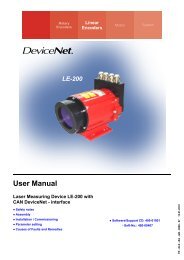
Technical Description <strong>BE</strong>-<strong>90</strong> P<strong>BE</strong>LEC<strong>TR</strong>ONIC GmbH4.3 LED indicators<strong>BE</strong>-<strong>90</strong> <strong>PB</strong>A <strong>BE</strong>-<strong>90</strong> <strong>PB</strong> internal green LED indicates in <strong>the</strong> reading window whe<strong>the</strong>r or not <strong>the</strong>supply voltage is present.<strong>BE</strong>-<strong>90</strong> CU <strong>PB</strong>3 / <strong>BE</strong>-<strong>90</strong> CU <strong>PB</strong>5On top of <strong>the</strong> modular hood with integrated connectors a red/green status LED is locatedbetween <strong>the</strong> M12 connectors DP IN and DP Out. It indicates <strong>the</strong> state of <strong>the</strong>Profibus connection.StateMeaningoffvoltage offgreen flashinginitialisation of <strong>the</strong> device, establishment of <strong>the</strong> PROFIBUScommunicationgreen, continuous light data operationred, flashingerror on PROFIBUS, error can be resolved by a resetred, continuous light error on PROFIBUS, error cannot be resolved by a resetorange, continuous light SERVICE operation activeTable 4-2: LED states <strong>BE</strong>-<strong>90</strong> CU <strong>PB</strong>3 / <strong>BE</strong>-<strong>90</strong> CU <strong>PB</strong>54.4 Device construction and componentsA modular hood with integrated connectors of <strong>the</strong> type <strong>BE</strong>-<strong>90</strong> CU <strong>PB</strong>3 or<strong>BE</strong>-<strong>90</strong> CU <strong>PB</strong>5 is always part of a <strong>BE</strong>-<strong>90</strong> <strong>PB</strong>. The purpose of both hoods is to connect<strong>the</strong> <strong>BE</strong>-<strong>90</strong> <strong>PB</strong> to <strong>the</strong> Profibus. For this, <strong>the</strong>y feature one Profibus IN and one ProfibusOUT connection each, as well as an internal switch <strong>for</strong> address setting.If only <strong>the</strong> connection to <strong>the</strong> Profibus is intended, type <strong>BE</strong>-<strong>90</strong> CU <strong>PB</strong>3 is sufficient.If, in addition, switching input and output are to be connected, an <strong>BE</strong>-<strong>90</strong> CU <strong>PB</strong>5 is required.Although switching inputs and outputs are available on <strong>the</strong> voltage supply connector,<strong>the</strong> switching inputs of <strong>the</strong> <strong>BE</strong>-<strong>90</strong> CU <strong>PB</strong>5 have <strong>the</strong> advantage that a standardsensor connector can be used.Figure 4-1: <strong>BE</strong>-<strong>90</strong> <strong>PB</strong> with <strong>BE</strong>-<strong>90</strong> CU <strong>PB</strong>5<strong>TR</strong>-ELEC<strong>TR</strong>ONIC GmbH, Global Quality Management, Eglishalde 6, 78647 Trossingen, Tel. ++49 (0)7425-228-0, Fax ++49 (0)7425-228-33Date: 08.07.2002 <strong>TR</strong> - E - BA - GB - 0025 - 00 Page 13 of 50
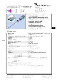
Technical Description <strong>BE</strong>-<strong>90</strong> P<strong>BE</strong>LEC<strong>TR</strong>ONIC GmbH4.5 Dimensioned and connecting drawings<strong>BE</strong>-<strong>90</strong> <strong>PB</strong>Figure 4-2: Dimensioned Drawing <strong>BE</strong>-<strong>90</strong> <strong>PB</strong><strong>BE</strong>-<strong>90</strong> CU <strong>PB</strong>3 / <strong>BE</strong>-<strong>90</strong> CU <strong>PB</strong>5<strong>BE</strong>-<strong>90</strong> CU <strong>PB</strong>3<strong>BE</strong>-<strong>90</strong> CU <strong>PB</strong>5A = <strong>BE</strong>-<strong>90</strong> <strong>PB</strong>Figure 4-3: Dimensioned drawing <strong>BE</strong>-<strong>90</strong> CU <strong>PB</strong>3 / <strong>BE</strong>-<strong>90</strong> CU <strong>PB</strong>5<strong>TR</strong>-ELEC<strong>TR</strong>ONIC GmbH, Global Quality Management, Eglishalde 6, 78647 Trossingen, Tel. ++49 (0)7425-228-0, Fax ++49 (0)7425-228-33Date: 08.07.2002 <strong>TR</strong> - E - BA - GB - 0025 - 00 Page 14 of 50
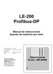
Technical Description <strong>BE</strong>-<strong>90</strong> P<strong>BE</strong>LEC<strong>TR</strong>ONIC GmbHScanning Curve <strong>BE</strong>-<strong>90</strong> <strong>PB</strong><strong>BE</strong>-<strong>90</strong> <strong>PB</strong>Working range<strong>BE</strong>-<strong>90</strong> <strong>PB</strong>Distance in mmFigure 4-4: Scanning Curve <strong>BE</strong>-<strong>90</strong> <strong>PB</strong><strong>TR</strong>-ELEC<strong>TR</strong>ONIC GmbH, Global Quality Management, Eglishalde 6, 78647 Trossingen, Tel. ++49 (0)7425-228-0, Fax ++49 (0)7425-228-33Date: 08.07.2002 <strong>TR</strong> - E - BA - GB - 0025 - 00 Page 15 of 50
Technical Description <strong>BE</strong>-<strong>90</strong> P<strong>BE</strong>LEC<strong>TR</strong>ONIC GmbH5 Order designationiNotice!Products manufactured by <strong>TR</strong>-<strong>Electronic</strong> GmbH can be ordered from any of <strong>the</strong>distributor and service addresses listed on <strong>the</strong> last page.5.1 Read head, RH (stand-alone unit)Explanation of <strong>the</strong>order designationThe order designation is structured according to <strong>the</strong> following scheme:40803-1ABCDThe letters A - D represent <strong>the</strong> following device variants:• A interface 1 = SSI (synchronous-serial)2 = PROFIBUS, RS485• B extension always 0• C extension always 0• D option (H) 0 = without option1 = -30 - +40°CAvailable device variants:<strong>BE</strong>-<strong>90</strong> RH SSI 40803-11000<strong>BE</strong>-<strong>90</strong> RH SSI + H 40803-11001<strong>BE</strong>-<strong>90</strong> RH <strong>PB</strong> 40803-12000<strong>BE</strong>-<strong>90</strong> RH <strong>PB</strong> + H 40803-12001Read Head SSI without optionRead Head SSI with option -30 - +40°CRead Head Profibus without optionRead Head Profibus with option -30 - +40°CRHSSI<strong>PB</strong>H= Read Head= Synchronous-Serial-Interface= Profibus= HeatingPlease indicate <strong>the</strong>se designations at <strong>the</strong> order.<strong>TR</strong>-ELEC<strong>TR</strong>ONIC GmbH, Global Quality Management, Eglishalde 6, 78647 Trossingen, Tel. ++49 (0)7425-228-0, Fax ++49 (0)7425-228-33Date: 08.07.2002 <strong>TR</strong> - E - BA - GB - 0025 - 00 Page 16 of 50
Technical Description <strong>BE</strong>-<strong>90</strong> P<strong>BE</strong>LEC<strong>TR</strong>ONIC GmbH5.2 Connection-Unit, CU (modular hood)Explanation of <strong>the</strong>order designationThe order designation is structured according to <strong>the</strong> following scheme:40803-22ABCThe letters A - C represent <strong>the</strong> following device variants:• A extension always 0• B extension always 0• C connection technique 2 = Modular hood <strong>for</strong> <strong>BE</strong>-<strong>90</strong> <strong>PB</strong> with3 x M12 connectors3 = Modular hood <strong>for</strong> <strong>BE</strong>-<strong>90</strong> <strong>PB</strong> with5 x M12 connectorsAvailable connection variants:<strong>BE</strong>-<strong>90</strong> CU <strong>PB</strong>3 40803-22002<strong>BE</strong>-<strong>90</strong> CU <strong>PB</strong>5 40803-22003Hood with 3 x M12 connectorsHood with 5 x M12 connectorsCU<strong>PB</strong>= Connecting Unit= PROFIBUS-InterfacePlease indicate <strong>the</strong>se designations at <strong>the</strong> order.5.3 Profibus Connector, COExplanation of <strong>the</strong>order designationMaleConnectorFemaleConnectorTerminatorThe order designation is structured according to <strong>the</strong> following scheme:40803-4ABCDThe letters A - D represent <strong>the</strong> following connector variants:• A - C extension always 0• D connector variants3 = 5 pol. Male connector <strong>for</strong> <strong>BE</strong>-<strong>90</strong> connection unit4 = 5 pol. Female connector <strong>for</strong> <strong>BE</strong>-<strong>90</strong> connection unit5 = 4 pol. Male connector, Profibus terminatingresistor <strong>for</strong> <strong>BE</strong>-<strong>90</strong> connection-unitAvailable connector variants:<strong>BE</strong>-<strong>90</strong> CO MA 5P 40803-40003 Connector, shielded, M12-connector 5pol. PG9, <strong>for</strong> signal line<strong>BE</strong>-<strong>90</strong> CO FE 5P 40803-40004 Connector, shielded, M12-socket 5pol. PG9, <strong>for</strong> signal line<strong>BE</strong>-<strong>90</strong> CO TE 5P 40803-40005 Profibus terminating resistor, connector M12-B, 4poleCO = Connector, MA = Male, FE = Female, TE TerminatorPlease indicate <strong>the</strong>se designations at <strong>the</strong> order.<strong>TR</strong>-ELEC<strong>TR</strong>ONIC GmbH, Global Quality Management, Eglishalde 6, 78647 Trossingen, Tel. ++49 (0)7425-228-0, Fax ++49 (0)7425-228-33Date: 08.07.2002 <strong>TR</strong> - E - BA - GB - 0025 - 00 Page 17 of 50
Technical Description <strong>BE</strong>-<strong>90</strong> P<strong>BE</strong>LEC<strong>TR</strong>ONIC GmbH5.4 Software, SWExplanation of <strong>the</strong>order designationThe order designation is structured according to <strong>the</strong> following scheme:40803-3ABCDThe letters A - D represent <strong>the</strong> following software variants:• A interface 1 = SSI (Synchronous-Serial)2 = PROFIBUS, RS485• BCD software-no. until now "000" <strong>for</strong> both variantsAvailable software variants:<strong>BE</strong>-<strong>90</strong> SW SSI 40803-31000<strong>BE</strong>-<strong>90</strong> SW <strong>PB</strong> 40803-32000SSI software variantProfibus software variant, device master files (GSD)SWSSI<strong>PB</strong>= Software= Synchronous-Serial-Interface= ProfibusPlease indicate <strong>the</strong>se designations at <strong>the</strong> order.<strong>TR</strong>-ELEC<strong>TR</strong>ONIC GmbH, Global Quality Management, Eglishalde 6, 78647 Trossingen, Tel. ++49 (0)7425-228-0, Fax ++49 (0)7425-228-33Date: 08.07.2002 <strong>TR</strong> - E - BA - GB - 0025 - 00 Page 18 of 50
Technical Description <strong>BE</strong>-<strong>90</strong> P<strong>BE</strong>LEC<strong>TR</strong>ONIC GmbH5.5 Fastening accessories, FAThe mounting unit is available <strong>for</strong> mounting <strong>the</strong> <strong>BE</strong>-<strong>90</strong>. It is designed <strong>for</strong> rod installation.Explanation of <strong>the</strong>order designationThe order designation is structured according to <strong>the</strong> following scheme:40803-5ABCDThe letters A - D represent <strong>the</strong> following mounting variants:• A extension always 0• B extension always 0• C extension always 0• D mounting element 1 = Mounting element <strong>BE</strong>-<strong>90</strong> / Connection-UnitAvailable mounting variants:<strong>BE</strong>-<strong>90</strong> FA-001 40803-50001Mounting element (dove tail <strong>for</strong> round pipes) between<strong>BE</strong>-<strong>90</strong> and connection-unitFA= FastenerPlease indicate <strong>the</strong>se designations at <strong>the</strong> order.Figure 5-1: Mounting element <strong>BE</strong>-<strong>90</strong><strong>TR</strong>-ELEC<strong>TR</strong>ONIC GmbH, Global Quality Management, Eglishalde 6, 78647 Trossingen, Tel. ++49 (0)7425-228-0, Fax ++49 (0)7425-228-33Date: 08.07.2002 <strong>TR</strong> - E - BA - GB - 0025 - 00 Page 19 of 50
Technical Description <strong>BE</strong>-<strong>90</strong> P<strong>BE</strong>LEC<strong>TR</strong>ONIC GmbH5.6 Special barcode band, BCExplanation of <strong>the</strong>order designationThe order designation is structured according to <strong>the</strong> following scheme:40803-6ABCDThe letters A - D represent <strong>the</strong> following barcode band length• ABCD barcode bandlengthTotal length in 10 m stepsThe length begins with <strong>the</strong> first meterExample: 40803-60002 = 20 m (0 - 20 m)Available barcode band lengths:<strong>BE</strong>-<strong>90</strong> BC 020 40803-60000<strong>BE</strong>-<strong>90</strong> BC 010 40803-60001<strong>BE</strong>-<strong>90</strong> BC 020 40803-60002<strong>BE</strong>-<strong>90</strong> BC 030 40803-60003<strong>BE</strong>-<strong>90</strong> BC 040 40803-60004<strong>BE</strong>-<strong>90</strong> BC 050 40803-60005<strong>BE</strong>-<strong>90</strong> BC 060 40803-60006<strong>BE</strong>-<strong>90</strong> BC 070 40803-60007<strong>BE</strong>-<strong>90</strong> BC 080 40803-60008<strong>BE</strong>-<strong>90</strong> BC 0<strong>90</strong> 40803-60009<strong>BE</strong>-<strong>90</strong> BC 100 40803-60010<strong>BE</strong>-<strong>90</strong> BC 200 40803-60020<strong>Barcode</strong> band, 0 - 5 m length<strong>Barcode</strong> band, 0 - 10 m length<strong>Barcode</strong> band, 0 - 20 m length<strong>Barcode</strong> band, 0 - 30 m length<strong>Barcode</strong> band, 0 - 40 m length<strong>Barcode</strong> band, 0 - 50 m length<strong>Barcode</strong> band, 0 - 60 m length<strong>Barcode</strong> band, 0 - 70 m length<strong>Barcode</strong> band, 0 - 80 m length<strong>Barcode</strong> band, 0 - <strong>90</strong> m length<strong>Barcode</strong> band, 0 - 100 m length<strong>Barcode</strong> band, 0 - 200 m lengthBC= <strong>Barcode</strong> bandPlease indicate <strong>the</strong>se designations at <strong>the</strong> order.5.6.1 Special barcode band (replacement)Must, by a damage caused, only a certain part of a barcode band to be replaced, <strong>the</strong>damaged bar code piece can be reordered. The article number <strong>BE</strong>-<strong>90</strong> BC SA 40803-70001 must be indicated with specification of <strong>the</strong> start- and end-value of <strong>the</strong> damagedbarcode band.<strong>TR</strong>-ELEC<strong>TR</strong>ONIC GmbH, Global Quality Management, Eglishalde 6, 78647 Trossingen, Tel. ++49 (0)7425-228-0, Fax ++49 (0)7425-228-33Date: 08.07.2002 <strong>TR</strong> - E - BA - GB - 0025 - 00 Page 20 of 50
Technical Description <strong>BE</strong>-<strong>90</strong> P<strong>BE</strong>LEC<strong>TR</strong>ONIC GmbH6 Installation6.1 Storage, TransportationAttention!When transporting, package <strong>the</strong> device so that it is protected against collision and humidity.Optimal protection is achieved when using <strong>the</strong> original packaging. Heed <strong>the</strong> requiredenvironmental conditions specified in <strong>the</strong> technical data.Unpacking• Check <strong>the</strong> packaging <strong>for</strong> any damage. If damage is found, notify <strong>the</strong> post office orshipping agent as well as <strong>the</strong> supplier.• Check <strong>the</strong> delivery contents using your order and <strong>the</strong> delivery papers:- delivered quantity- device type and model as indicated on <strong>the</strong> nameplate- accessories- operation manual with GSD file• Save <strong>the</strong> original packaging <strong>for</strong> later storage or shipping.If you have any questions concerning your shipment, please contact your supplier oryour local <strong>TR</strong>-<strong>Electronic</strong> sales office.• Observe <strong>the</strong> local regulations regarding disposal and packaging.Cleaning• Clean <strong>the</strong> glass window of <strong>the</strong> <strong>BE</strong>-<strong>90</strong> <strong>PB</strong> with a soft cloth be<strong>for</strong>e mounting. Removeall packaging remains, e.g. carton fibres or Styrofoam balls.Attention!Do not use aggressive cleaning agents such as thinner or acetone <strong>for</strong> cleaning <strong>the</strong> deviceand <strong>the</strong> barcode band.<strong>TR</strong>-ELEC<strong>TR</strong>ONIC GmbH, Global Quality Management, Eglishalde 6, 78647 Trossingen, Tel. ++49 (0)7425-228-0, Fax ++49 (0)7425-228-33Date: 08.07.2002 <strong>TR</strong> - E - BA - GB - 0025 - 00 Page 21 of 50
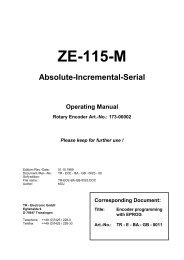
Technical Description <strong>BE</strong>-<strong>90</strong> P<strong>BE</strong>LEC<strong>TR</strong>ONIC GmbH6.2 MountingAccessoriesFor installation a mounting system is available. It may be ordered separately from <strong>TR</strong>-<strong>Electronic</strong>. For order numbers, see chapter 5.5 "Fastening accessories, FA" on page 19.Mounting <strong>the</strong> <strong>BE</strong>-<strong>90</strong> <strong>PB</strong>There are two basic types of mounting arrangements <strong>for</strong> <strong>the</strong> <strong>BE</strong>-<strong>90</strong> <strong>PB</strong>.• using <strong>the</strong> dovetail groove and <strong>the</strong> corresponding mounting accessories (see Figure 6-1)• using <strong>the</strong> fastening threads on <strong>the</strong> backside of <strong>the</strong> devices (chapter 4.5)Mounting Example <strong>BE</strong>-<strong>90</strong> <strong>PB</strong>Figure 6-1: Mounting Example <strong>BE</strong>-<strong>90</strong> <strong>PB</strong><strong>TR</strong>-ELEC<strong>TR</strong>ONIC GmbH, Global Quality Management, Eglishalde 6, 78647 Trossingen, Tel. ++49 (0)7425-228-0, Fax ++49 (0)7425-228-33Date: 08.07.2002 <strong>TR</strong> - E - BA - GB - 0025 - 00 Page 22 of 50
Technical Description <strong>BE</strong>-<strong>90</strong> P<strong>BE</strong>LEC<strong>TR</strong>ONIC GmbH6.2.1 Device arrangementSelecting a Mounting LocationIn order to select <strong>the</strong> right mounting location, several factors must be considered:• The scanning range determined from <strong>the</strong> scanning curve must be adhered to at alllocations at which a position determination is to be made• The <strong>BE</strong>-<strong>90</strong> should be mounted inclined 10° from vertical towards <strong>the</strong> barcode bandto ensure that <strong>the</strong> positioning results are reliably obtained even if <strong>the</strong> barcode bandis soiled.iiFigure 6-2: Device Arrangement to <strong>the</strong> <strong>Barcode</strong> BandNotice!The best functionality is obtained when:• <strong>the</strong> <strong>BE</strong>-<strong>90</strong> is guided parallel to <strong>the</strong> band• <strong>the</strong> permitted working range is not exitedNotice!On <strong>the</strong> <strong>BE</strong>-<strong>90</strong> <strong>PB</strong>, <strong>the</strong> beam is not emitted perpendicular to <strong>the</strong> cover of <strong>the</strong> housing, butwith an angle of 10 ° towards <strong>the</strong> top. This angle is intended to prevent total reflectionon <strong>the</strong> barcode band.<strong>TR</strong>-ELEC<strong>TR</strong>ONIC GmbH, Global Quality Management, Eglishalde 6, 78647 Trossingen, Tel. ++49 (0)7425-228-0, Fax ++49 (0)7425-228-33Date: 08.07.2002 <strong>TR</strong> - E - BA - GB - 0025 - 00 Page 23 of 50
Technical Description <strong>BE</strong>-<strong>90</strong> P<strong>BE</strong>LEC<strong>TR</strong>ONIC GmbHFigure 6-3: Beam outlet on <strong>the</strong> <strong>BE</strong>-<strong>90</strong> <strong>PB</strong>Mounting Location• When selecting a mounting location, pay attention to- maintaining <strong>the</strong> required environmental conditions (humidity, temperature),- possible soiling of <strong>the</strong> reading window due to liquids, abrasion by boxes, orpackaging material residues.- lowest possible chance of damage to <strong>the</strong> <strong>BE</strong>-<strong>90</strong> <strong>PB</strong> by mechanical collisionor jammed parts.<strong>TR</strong>-ELEC<strong>TR</strong>ONIC GmbH, Global Quality Management, Eglishalde 6, 78647 Trossingen, Tel. ++49 (0)7425-228-0, Fax ++49 (0)7425-228-33Date: 08.07.2002 <strong>TR</strong> - E - BA - GB - 0025 - 00 Page 24 of 50
Technical Description <strong>BE</strong>-<strong>90</strong> P<strong>BE</strong>LEC<strong>TR</strong>ONIC GmbHApplication ExampleFigure 6-4: Application Example<strong>TR</strong>-ELEC<strong>TR</strong>ONIC GmbH, Global Quality Management, Eglishalde 6, 78647 Trossingen, Tel. ++49 (0)7425-228-0, Fax ++49 (0)7425-228-33Date: 08.07.2002 <strong>TR</strong> - E - BA - GB - 0025 - 00 Page 25 of 50
Technical Description <strong>BE</strong>-<strong>90</strong> P<strong>BE</strong>LEC<strong>TR</strong>ONIC GmbH6.3 Address settingIn <strong>the</strong> modular hoods with integrated connectors <strong>BE</strong>-<strong>90</strong> CU <strong>PB</strong>3 and <strong>BE</strong>-<strong>90</strong> CU <strong>PB</strong>5,<strong>the</strong> Profibus address can be set via two rotary switches and one slide switch.The address switches are positioned as follows.Figure 6-5: View of <strong>the</strong> Inside of <strong>the</strong> <strong>BE</strong>-<strong>90</strong> CU6.4 ConnectionAttention!Never open <strong>the</strong> device yourself, as this may compromise protection class IP 65.Be<strong>for</strong>e connecting <strong>the</strong> device, be sure that <strong>the</strong> supply voltage agrees with <strong>the</strong> valueprinted on <strong>the</strong> nameplate.Connection of <strong>the</strong> device and maintenance work while under voltage must only be carriedout by a qualified electrician.The power supply unit <strong>for</strong> <strong>the</strong> generation of <strong>the</strong> supply voltage <strong>for</strong> <strong>the</strong> <strong>BE</strong>-<strong>90</strong> <strong>PB</strong> and <strong>the</strong>respective connector units must have a secure electrical insulation through double insulationand safety trans<strong>for</strong>mers according to DIN VDE 0551 (IEC 742).Be sure that <strong>the</strong> earthing conductor is connected correctly. Error-free operation is onlyguaranteed when <strong>the</strong> device is properly ear<strong>the</strong>d.If faults cannot be corrected, <strong>the</strong> device should be removed from operation and protectedagainst possible use.<strong>TR</strong>-ELEC<strong>TR</strong>ONIC GmbH, Global Quality Management, Eglishalde 6, 78647 Trossingen, Tel. ++49 (0)7425-228-0, Fax ++49 (0)7425-228-33Date: 08.07.2002 <strong>TR</strong> - E - BA - GB - 0025 - 00 Page 26 of 50
Technical Description <strong>BE</strong>-<strong>90</strong> P<strong>BE</strong>LEC<strong>TR</strong>ONIC GmbH6.4.1 Connecting <strong>the</strong> <strong>BE</strong>-<strong>90</strong> <strong>PB</strong>Connections <strong>BE</strong>-<strong>90</strong> CU <strong>PB</strong>3 / <strong>BE</strong>-<strong>90</strong> CU <strong>PB</strong>5Figure 6-6: Connection assignment of <strong>the</strong> <strong>BE</strong>-<strong>90</strong> <strong>PB</strong> with <strong>BE</strong>-<strong>90</strong> CU <strong>PB</strong>3 / <strong>BE</strong>-<strong>90</strong> CU <strong>PB</strong>5Wiring Description PWR IN (Voltage Supply)Pin 1 VIN 10 ... 30 VDC voltage supplyPin 2 SW OUT Switching outputPin 3 GND IN GND <strong>for</strong> voltage supplyPin 4 SW IN Switching inputPin 5 PE Protected EarthTable 6-1: Pin Assignment PWR INConnection Description SW IN/OUT (Switching Input/Output)Pin 1 V OUT 24 V voltage supply <strong>for</strong> <strong>the</strong> sensorsPin 2 SW OUT Switching outputPin 3 GND OUT GND <strong>for</strong> <strong>the</strong> sensorsPin 4 SW IN Switching inputPin 5 PE Protected EarthTable 6-2: Pin Assignment SW IN/OUT<strong>TR</strong>-ELEC<strong>TR</strong>ONIC GmbH, Global Quality Management, Eglishalde 6, 78647 Trossingen, Tel. ++49 (0)7425-228-0, Fax ++49 (0)7425-228-33Date: 08.07.2002 <strong>TR</strong> - E - BA - GB - 0025 - 00 Page 27 of 50
Technical Description <strong>BE</strong>-<strong>90</strong> P<strong>BE</strong>LEC<strong>TR</strong>ONIC GmbHYou can configure <strong>the</strong> switching input and output according to your requirements.Please refer to Figure 6-7. If you use a sensor with a standard M12 connector, <strong>the</strong>nplease note <strong>the</strong> following:Attention!Only use sensors without switching output on pin 2 or sensor wiring configured withoutpin 2, as <strong>the</strong> switching output is not protected against feedback. For example, having<strong>the</strong> inverted sensor output incident on pin 2 leads to erroneous behaviour of <strong>the</strong> switchingoutput.Connection Description Profibus IN/OUTPin 1 VCC 5 V <strong>for</strong> bus terminationPin 2 N N or A line of <strong>the</strong> ProfibusPin 3 GND Ground <strong>for</strong> bus terminationPin 4 P P or B line of <strong>the</strong> ProfibusPin 5 PE protective conductorTable 6-3: Pin Assignment DP IN/OUT6.4.2 Connection of switching inputs and outputsThe <strong>BE</strong>-<strong>90</strong> <strong>PB</strong> is provided with a switching input and a switching output. The connectionof <strong>the</strong> switching inputs and outputs is carried out according to Figure 6-7.Figure 6-7: Connection Diagram Switching Inputs and Outputs <strong>BE</strong>-<strong>90</strong> <strong>PB</strong><strong>TR</strong>-ELEC<strong>TR</strong>ONIC GmbH, Global Quality Management, Eglishalde 6, 78647 Trossingen, Tel. ++49 (0)7425-228-0, Fax ++49 (0)7425-228-33Date: 08.07.2002 <strong>TR</strong> - E - BA - GB - 0025 - 00 Page 28 of 50
Technical Description <strong>BE</strong>-<strong>90</strong> P<strong>BE</strong>LEC<strong>TR</strong>ONIC GmbHSwitching inputIn <strong>the</strong> standard setting, you can reset output of <strong>the</strong> positioning data (preset) via <strong>the</strong>switching input connection SWIN by connecting SWIN (pin 4) and VOUT (pin 1).Switching outputiThe switching output connection between SWOUT (pin 2) and GND (pin 3) is normallyopen. In <strong>the</strong> standard setting, SWOUT is closed in <strong>the</strong> case of a positioning error.Notice!You can configure <strong>the</strong> switching inputs and outputs according to your requirements byusing <strong>the</strong> modules 7 (switching input) and 8 (switching output).6.5 Disassembling, Packing, DisposingRepackingFor later reuse, <strong>the</strong> device is to be packed so that it is protected against shocks anddampness. Optimal protection is achieved when using <strong>the</strong> original packaging.iNotice!Electrical scrap is a special waste product! Observe <strong>the</strong> locally applicable regulationsregarding disposal of <strong>the</strong> product.<strong>TR</strong>-ELEC<strong>TR</strong>ONIC GmbH, Global Quality Management, Eglishalde 6, 78647 Trossingen, Tel. ++49 (0)7425-228-0, Fax ++49 (0)7425-228-33Date: 08.07.2002 <strong>TR</strong> - E - BA - GB - 0025 - 00 Page 29 of 50
Technical Description <strong>BE</strong>-<strong>90</strong> P<strong>BE</strong>LEC<strong>TR</strong>ONIC GmbH7 Profibus7.1 General in<strong>for</strong>mationThe <strong>BE</strong>-<strong>90</strong> <strong>PB</strong> with <strong>BE</strong>-<strong>90</strong> CU <strong>PB</strong>3/<strong>BE</strong>-<strong>90</strong> CU <strong>PB</strong>5 was developed as a Profibus device.The functionality of <strong>the</strong> device is defined via parameter sets which are clustered inmodules. These modules are included in a GSD file, which is supplied as an integralpart of <strong>the</strong> device. By using a user-specific project tool, such as, e.g., Simatic Manager<strong>for</strong> <strong>the</strong> programmable logic control by Siemens, <strong>the</strong> required modules are integrated intoa project during commissioning and its settings and parameters are adjusted accordingly.These modules are provided by <strong>the</strong> GSD file.All input and output modules described in this documentation are described from <strong>the</strong>controller’s perspective:• Input data arrives at <strong>the</strong> controller• Output data is sent out by <strong>the</strong> controller.7.1.1 GSD FileThe GSD file can be found on <strong>the</strong> disc supplied with this documentation.This file stores all <strong>the</strong> data required <strong>for</strong> <strong>the</strong> operation of <strong>the</strong> <strong>BE</strong>-<strong>90</strong> <strong>PB</strong>. This data consistsof device parameters required <strong>for</strong> operation of <strong>the</strong> <strong>BE</strong>-<strong>90</strong> <strong>PB</strong>, Profibus operationparameters, and <strong>the</strong> definition of <strong>the</strong> control and status bits. If parameters are changedin <strong>the</strong> project, <strong>for</strong> example, <strong>the</strong>se changes are stored in <strong>the</strong> project, not in <strong>the</strong> GSD file.The GSD file is a certified part of <strong>the</strong> device and must not be changed manually. The fileis not changed by <strong>the</strong> system ei<strong>the</strong>r.7.2 Structure of <strong>the</strong> project modulesIn <strong>the</strong> current version, a total of 17 modules are available <strong>for</strong> use. The modules may beincluded into <strong>the</strong> project according to requirements and application.The modules fall into <strong>the</strong> following categories:• Parameter module <strong>for</strong> <strong>the</strong> scanner configuration• Status or control modules that influence <strong>the</strong> input and output data.• Modules that may include both parameters and control or status in<strong>for</strong>mation.iThe category of each module is marked with a cross in <strong>the</strong> overview.Notice!At least one module must be activated to permit operation of <strong>the</strong> device at <strong>the</strong> Profibus DP.<strong>TR</strong>-ELEC<strong>TR</strong>ONIC GmbH, Global Quality Management, Eglishalde 6, 78647 Trossingen, Tel. ++49 (0)7425-228-0, Fax ++49 (0)7425-228-33Date: 08.07.2002 <strong>TR</strong> - E - BA - GB - 0025 - 00 Page 30 of 50
Technical Description <strong>BE</strong>-<strong>90</strong> P<strong>BE</strong>LEC<strong>TR</strong>ONIC GmbH7.2.1 Overview of <strong>the</strong> project modulesiNotice!Inputs and outputs are described from <strong>the</strong> perspective of <strong>the</strong> Profibus master.ModuleNr.Name of <strong>the</strong> module Description Parameter Output data Input data1Module 1:Position valuePosition value X X2Module 2:ResolutionSetting of position valueresolutionX3Module 3:Static presetValue setting <strong>for</strong> staticpreset functionXX4Module 4:Dynamic presetValue setting <strong>for</strong> dynamicpreset functionX5Module 5:Offset valueValue setting <strong>for</strong> offsetvalueX6Module 6:ScalingValue setting <strong>for</strong> positionvalue scalingX7Module 7:Switching inputSpecification of switchinginputXX8Module 8:Switching outputSpecification of switchingoutputXX9Module 9:ControllerControls start of measuringprocessX X X10Module 10:Measurement valueacquisitionDefines min. start of measurementand max. end ofmeasurementX11Module 11:Measurement valueprocessingParameter <strong>for</strong> internalprocessing of measurementvalueXX12Module 12:Status<strong>BE</strong>-<strong>90</strong> status at ProfibusX13Module 13:Min – Max positionActivation of function usedto determine min/maxvaluesXX14Module 14:Static limit value 1Static preset of position 1; afunction is triggered whenposition is reachedX15Module 15:Static limit value 2Static preset of position 2; afunction is triggered whenposition is reachedX16Module 16:Dynamic limit value 1Dynamic preset of position1; a function is triggeredwhen position is reachedXX17Module 17:Dynamic limit value 2Dynamic preset of position2; a function is triggeredwhen position is reachedXXTable 7-1: Overview of <strong>the</strong> project modules<strong>TR</strong>-ELEC<strong>TR</strong>ONIC GmbH, Global Quality Management, Eglishalde 6, 78647 Trossingen, Tel. ++49 (0)7425-228-0, Fax ++49 (0)7425-228-33Date: 08.07.2002 <strong>TR</strong> - E - BA - GB - 0025 - 00 Page 31 of 50
Technical Description <strong>BE</strong>-<strong>90</strong> P<strong>BE</strong>LEC<strong>TR</strong>ONIC GmbH7.2.2 Module 1: Position valueDescriptionOutput of <strong>the</strong> current position value without additional in<strong>for</strong>mation, i.e. independent of<strong>the</strong> parameterised output <strong>for</strong>matting.ParameterParameterDescriptionRel.addressSign Output mode <strong>for</strong> sign 0 UNSIGNED 8Table 7-2: Parameters <strong>for</strong> module 1Data Type Value Range Standard Unit0:Binary representation1:Sign with value0 -Parameter length: 1 byteInput DataInput Data Description Address Data Type Value Range Init Value UnitPosition Current position 0 SIGNED 32Table 7-3: Input Data <strong>for</strong> module 1Input data length: 4 bytes consistently-10 000 000 …10 000 0000 Scaled<strong>TR</strong>-ELEC<strong>TR</strong>ONIC GmbH, Global Quality Management, Eglishalde 6, 78647 Trossingen, Tel. ++49 (0)7425-228-0, Fax ++49 (0)7425-228-33Date: 08.07.2002 <strong>TR</strong> - E - BA - GB - 0025 - 00 Page 32 of 50
Technical Description <strong>BE</strong>-<strong>90</strong> P<strong>BE</strong>LEC<strong>TR</strong>ONIC GmbH7.2.3 Module 2: ResolutionDescriptionThe resolution function defines <strong>the</strong> resolution <strong>for</strong> <strong>the</strong> position values and per<strong>for</strong>ms arounding correction.ParameterParameterDescriptionRel.addressData Type Value Range Standard UnitResolutionThe Parameter defines<strong>the</strong> resolution<strong>for</strong> <strong>the</strong> position0 UNSIGNED 81: 0.012: 0.13: 14: 105: 1006: 10003 mmTable 7-4: Parameters <strong>for</strong> module 2Parameter length: 1 byteInput DatanoneOutput Datanone7.2.4 Module 3: Static presetDescriptionThis module is used to preset a value which <strong>the</strong> <strong>BE</strong>-<strong>90</strong> is to output after an event (e.g. a24V level at <strong>the</strong> switching input or an event caused by a bit being set in <strong>the</strong> output data)has occurred. The value is stored permanently in <strong>the</strong> <strong>BE</strong>-<strong>90</strong>.ParameterParameterDescriptionRel.addressData Type Value Range Standard UnitPre-setvalueNew position valueafter preset0 UNSIGNED 320 …10 000 0000 mmTable 7-5: Parameters <strong>for</strong> module 3Parameter length: 4 bytesInput Datanone<strong>TR</strong>-ELEC<strong>TR</strong>ONIC GmbH, Global Quality Management, Eglishalde 6, 78647 Trossingen, Tel. ++49 (0)7425-228-0, Fax ++49 (0)7425-228-33Date: 08.07.2002 <strong>TR</strong> - E - BA - GB - 0025 - 00 Page 33 of 50
Technical Description <strong>BE</strong>-<strong>90</strong> P<strong>BE</strong>LEC<strong>TR</strong>ONIC GmbHOutput DataOutput Data Description Address Data Type Value Range UnitPreset teach Read-in of preset values 0.0 BytePreset resetResetting to default values,deactivation of presetfunctionTable 7-6: Output data <strong>for</strong> module 40.1 Byte0 = none0->1 = Teach0 = none0>1 = reset--7.2.5 Module 4: Dynamic presetDescriptionThis module is used to preset a value which <strong>the</strong> <strong>BE</strong>-<strong>90</strong> is to output after an event (e.g. a24V level at <strong>the</strong> switching input) has occurred. The value is stored permanently in <strong>the</strong><strong>BE</strong>-<strong>90</strong>.The preset value is defined using output data from <strong>the</strong> Profibus master.ParameternoneInput DatanoneOutput DataOutput Data Description Address Data Type Value Range Init Value UnitPreset-TeachPreset-ResetPres-set valueRead-in of presetvaluesResetting todefault values,switchover ofpreset functionNew positionvalue after presetTable 7-7: Output data <strong>for</strong> module 40.0 Byte0.1 ByteOutput data length: 4 bytes consistently1 UNSIGNED 320 = none0->1 = Teach0 = none0>1 = Reset010 000 0000 00 -0 mm<strong>TR</strong>-ELEC<strong>TR</strong>ONIC GmbH, Global Quality Management, Eglishalde 6, 78647 Trossingen, Tel. ++49 (0)7425-228-0, Fax ++49 (0)7425-228-33Date: 08.07.2002 <strong>TR</strong> - E - BA - GB - 0025 - 00 Page 34 of 50
Technical Description <strong>BE</strong>-<strong>90</strong> P<strong>BE</strong>LEC<strong>TR</strong>ONIC GmbH7.2.6 Module 5: Offset valueDescriptionThe start value function adds an offset value to <strong>the</strong> scaled position value.ParameterParameterDescriptionRel.addressData Type Value Range Standard UnitOffset valueOffset value added toposition value0 SIGNED 32-10 000 000 …10 000 0000 Scaled unitsTable 7-8: Parameters <strong>for</strong> module 5Parameter length: 4 bytesInput DatanoneOutput Datanone7.2.7 Module 6: ScalingDescriptionThe scaling function allows <strong>the</strong> position values to be converted to any unit of measurement.To do this, <strong>the</strong> position is multiplied by <strong>the</strong> scaling factor.ParameterParameterDescriptionRel.addressData Type Value Range Standard UnitScalingfactorScaling factor used toconvert positionvalues0 UNSIGNED 16 0-65535 1000 Per thousandTable 7-9: Parameters <strong>for</strong> module 6Parameter length: 2 bytesInput DatanoneOutput Datanone<strong>TR</strong>-ELEC<strong>TR</strong>ONIC GmbH, Global Quality Management, Eglishalde 6, 78647 Trossingen, Tel. ++49 (0)7425-228-0, Fax ++49 (0)7425-228-33Date: 08.07.2002 <strong>TR</strong> - E - BA - GB - 0025 - 00 Page 35 of 50
Technical Description <strong>BE</strong>-<strong>90</strong> P<strong>BE</strong>LEC<strong>TR</strong>ONIC GmbH7.2.8 Module 7: Switching inputDescriptionThe module defines <strong>the</strong> mode of operation of <strong>the</strong> digital switching input.ParameterParameter Description Address Data Type Value Range Standard UnitInversionModeDe-bouncingtimeStart-up delayMinimumswitch-on timeSwitch-offdelayFunctionThe parameter defines<strong>the</strong> logic of <strong>the</strong>incident signal. Incase of an inversion,an external HIGHlevel is interpretedinternally as a LO'Wlevel.The parameter canbe used to control <strong>the</strong>processing of <strong>the</strong>switching inputThe parameter definesa de-bouncingtime which is implementedin softwareThe parameter influences<strong>the</strong> timingduring switch-onThe parameter definesa minimum timeperiod be<strong>for</strong>e <strong>the</strong>signal is reset.The parameter definesa time delay <strong>for</strong><strong>the</strong> signal duringswitch-offThe parameter specifies<strong>the</strong> functionwhich is to be activatedor deactivatedby a change of statein <strong>the</strong> signal.0 UNSIGNED 81 UNSIGNED 80: No1: Yes0: Off1: On0 -1 -2 UNSIGNED 8 0 ... 255 5 1 ms3 UNSIGNED 16 0 ... 65535 0 1 ms5 UNSIGNED 16 0 ... 65535 0 1 ms7 UNSIGNED 16 0 ... 65535 0 1 ms9 UNSIGNED 80: no function4: Preset teach5: Min/Max Reset6: Hold Set7: Measurementstart9: MeasurementStop10: Limit value 1teach11: Limit value 2teach4 -Table 7-10: Parameters <strong>for</strong> module 7Parameter length: 10 bytes<strong>TR</strong>-ELEC<strong>TR</strong>ONIC GmbH, Global Quality Management, Eglishalde 6, 78647 Trossingen, Tel. ++49 (0)7425-228-0, Fax ++49 (0)7425-228-33Date: 08.07.2002 <strong>TR</strong> - E - BA - GB - 0025 - 00 Page 36 of 50
Technical Description <strong>BE</strong>-<strong>90</strong> P<strong>BE</strong>LEC<strong>TR</strong>ONIC GmbHInput DataInput Data Description Address Data Type Value Range Init Value UnitStateState of <strong>the</strong> signal of <strong>the</strong>switching input 10.0 Bit 0.1 0 -Table 7-11: Input data <strong>for</strong> module 7Input data length: 1 byte consistentlyOutput Datanone7.2.9 Module 8: Switching outputDescriptionThe module defines <strong>the</strong> mode of operation of <strong>the</strong> digital switching output.ParameterParameterDescriptionAddressData Type Value Range Standard UnitDC biaslevelSwitch ontimeSwitch onfunctionThe parameter defines <strong>the</strong>DC bias level of <strong>the</strong> switchingoutputThe parameter defines <strong>the</strong>switch-on time period <strong>for</strong><strong>the</strong> switching output. If <strong>the</strong>value is 0, <strong>the</strong> signal isstatic.The parameter specifies <strong>the</strong>events which can set <strong>the</strong>switching output.0 UNSIGNED 80: LOW (OV)1: HIGH (+Ub)0 -2 UNSIGNED 16 0 ... 1300 400 1 ms4Limit value 1 reached 4.2 0Limit value 1 not reached 4.3 0Measurement value outsidemeasurement value range4.4 0Measurement value inside4.5 Respectively 0measurement value rangeBits0: OffLimit value 2 reached 4.6 1: On 0Limit value 2 not reached 4.7 0After erroneous measurementAfter successful measurement4.10 14.11 0PROFIBUS positive edge 4.12 0PROFIBUS negative edge 4.130Table 7-12: Parameters <strong>for</strong> module 8<strong>TR</strong>-ELEC<strong>TR</strong>ONIC GmbH, Global Quality Management, Eglishalde 6, 78647 Trossingen, Tel. ++49 (0)7425-228-0, Fax ++49 (0)7425-228-33Date: 08.07.2002 <strong>TR</strong> - E - BA - GB - 0025 - 00 Page 37 of 50
Technical Description <strong>BE</strong>-<strong>90</strong> P<strong>BE</strong>LEC<strong>TR</strong>ONIC GmbHParameter Description Address Data Type Value Range Standard UnitSwitch offfunctionThe parameter specifies<strong>the</strong> events which canreset <strong>the</strong> switching output.6Limit value 1 reached 6.2 0Limit value 1 not reached 6.3 0Measurement valueoutside measurementvalue range6.4 0Measurement valueRespectivelyinside measurement 6.5 Bit0: Off0value range1: OnLimit value 2 reached 6.6 0Limit value 2 not reached 6.7 0After erroneous measurementAfter successful measurement6.10 06.11 1PROFIBUS positive edge 6.12 0PROFIBUS negativeedge6.13Table 7-12: Parameters <strong>for</strong> module 80-Parameter length: 8 bytesInput DatanoneOutput DataOutput Data Description Address Data Type Value Range Init Value UnitSwitchingoutputSignal used to set statusof switching output 1.Requirement: PROFIBUSedge is parameterised0.0 Bit0->1: positiveedge1->0: negativeedge-Table 7-13: Output data <strong>for</strong> module 8Output data length: 1 byte consistently<strong>TR</strong>-ELEC<strong>TR</strong>ONIC GmbH, Global Quality Management, Eglishalde 6, 78647 Trossingen, Tel. ++49 (0)7425-228-0, Fax ++49 (0)7425-228-33Date: 08.07.2002 <strong>TR</strong> - E - BA - GB - 0025 - 00 Page 38 of 50
Technical Description <strong>BE</strong>-<strong>90</strong> P<strong>BE</strong>LEC<strong>TR</strong>ONIC GmbH7.2.10 Module 9: ControllerDescriptionThe position controller schedules <strong>the</strong> timing of <strong>the</strong> position calculation by controlling <strong>the</strong>decoder and router using <strong>the</strong> output of <strong>the</strong> position values.The controller used to calculate <strong>the</strong> position receives <strong>the</strong> incoming external signals(e.g. switching input or commands) and uses <strong>the</strong>m to control <strong>the</strong> calculation process.Using parameters, it determines who is allowed to influence <strong>the</strong> states. The controllerconstitutes a dedicated task in a state machine.ParameterParameterDescriptionRel.addressData Type Value Range Standard UnitMeasurementstartmodeMeasurementstopmodePos_Control_Stop_TimeoutThe start modedetermines when<strong>the</strong> position measurementis started.The stop modedetermines when<strong>the</strong> position measurementis stoppedTime <strong>for</strong> stop timeout0 UNSIGNED 81 UNSIGNED 80: no function1: after initialisation2: After start eventas result of command,switchinginput or signal fromProfibus master0: no function1: valid measurementresult2: After certain time3: After certain timewith retrigger functionas result ofcommand4: After stop eventas result of commandor statusfrom switching input5: Error status1 -4 -2 UNSIGNED 16 0 ... 65535 1 0000 msTable 7-14: Parameters <strong>for</strong> module 9Parameter length: 4 bytes<strong>TR</strong>-ELEC<strong>TR</strong>ONIC GmbH, Global Quality Management, Eglishalde 6, 78647 Trossingen, Tel. ++49 (0)7425-228-0, Fax ++49 (0)7425-228-33Date: 08.07.2002 <strong>TR</strong> - E - BA - GB - 0025 - 00 Page 39 of 50
Technical Description <strong>BE</strong>-<strong>90</strong> P<strong>BE</strong>LEC<strong>TR</strong>ONIC GmbHInput DataInput Data Description Address Data Type Value Range Init Value UnitPos_Control_StateStatus of positioncontroller0 UNSIGNED 80: Init1: Idle2: Measure3: Polling0 -Table 7-15: Input data <strong>for</strong> module 9Input data length: 1 byte consistentlyOutput DataOutput Data Description Address Data Type Value Range Init Value UnitPos_Start_EventEvent which startsposition measurement0.0 Bit0: no change0 ->1: start0 -Pos_Stop_EventEvent which stopsposition measurement0.1 Bit0: no change0 ->1: stop0 -Table 7-16: Output data <strong>for</strong> module 9Output data length: 1 byte consistently<strong>TR</strong>-ELEC<strong>TR</strong>ONIC GmbH, Global Quality Management, Eglishalde 6, 78647 Trossingen, Tel. ++49 (0)7425-228-0, Fax ++49 (0)7425-228-33Date: 08.07.2002 <strong>TR</strong> - E - BA - GB - 0025 - 00 Page 40 of 50
Technical Description <strong>BE</strong>-<strong>90</strong> P<strong>BE</strong>LEC<strong>TR</strong>ONIC GmbH7.2.11 Module 10: Measurement value acquisitionDescriptionThe measurement value acquisition module analyses all bar codes in <strong>the</strong> scan and providesa list of raw position data <strong>for</strong> <strong>the</strong> scan.ParameterParameterDescriptionRel.AddressData Type Value Range- Standard UnitMax. measurementlengthMaximum permittedmeasurementlength0 UNSIGNED 320h ...7FFF FFFFh10 000 000 mmMin. measurementlengthMinimum permittedmeasurementlength4 UNSIGNED 320h ...7FFF FFFFh0 mmTable 7-17: Parameters <strong>for</strong> module 10Parameter length: 8 bytesInput DatanoneOutput Datanone<strong>TR</strong>-ELEC<strong>TR</strong>ONIC GmbH, Global Quality Management, Eglishalde 6, 78647 Trossingen, Tel. ++49 (0)7425-228-0, Fax ++49 (0)7425-228-33Date: 08.07.2002 <strong>TR</strong> - E - BA - GB - 0025 - 00 Page 41 of 50
Technical Description <strong>BE</strong>-<strong>90</strong> P<strong>BE</strong>LEC<strong>TR</strong>ONIC GmbH7.2.12 Module 11: Measurement value processingDescriptionThe measurement value processing module integrates <strong>the</strong> acquired raw position data to<strong>for</strong>m a position value.ParameterParameterDescriptionRel.AddressData Type Value Range Standard UnitIntegrationdepthNumber of consecutivescanswhich are to beused <strong>for</strong> positiondetermination0 UNSIGNED 8 0 … 255 8 MeasurementsTable 7-18: Parameters <strong>for</strong> module 11Parameter length: 2 bytesInput DatanoneOutput DataOutput Data Description Address Data Type Value Range Init Value UnitCount directionCount direction<strong>for</strong> positioncalculation0.0 Bit0: normal1: inverse0 -Table 7-19: Output data <strong>for</strong> module 11Output data length: 1 byte consistently<strong>TR</strong>-ELEC<strong>TR</strong>ONIC GmbH, Global Quality Management, Eglishalde 6, 78647 Trossingen, Tel. ++49 (0)7425-228-0, Fax ++49 (0)7425-228-33Date: 08.07.2002 <strong>TR</strong> - E - BA - GB - 0025 - 00 Page 42 of 50
Technical Description <strong>BE</strong>-<strong>90</strong> P<strong>BE</strong>LEC<strong>TR</strong>ONIC GmbH7.2.13 Module 12: StatusDescriptionThis module defines various items of status in<strong>for</strong>mation from <strong>the</strong> <strong>BE</strong>-<strong>90</strong> <strong>PB</strong>.ParameternoneInput DataInput DataDescriptionAddressDataTypeValue Range Init Value UnitMeasurement error[MeasurementValue Processing]Indicates that novalid integrationvalue could bedetermined.0.0 Bit0 : OK1 : Integration error0 -Range status[MeasurementValue Acquisition]Indicates thatmeasurementrange has beenexceeded0.1 Bit0 : OK in <strong>the</strong> measurementrange1 : Measurementrange exceeded0 -Limit value status 1[MeasurementValue Monitoring]Indicates that limitvalue 1 has beenexceeded or undershot0.4 Bit0: Not exceeded1: Exceeded0 -Limit value status 2[MeasurementValue Monitoring]Indicates that limitvalue 2 has beenexceeded or undershot0.5 Bit0: Not exceeded1: Exceeded0 -Table 7-20: Input data <strong>for</strong> module 12Input data length: 1 byte consistentlyOutput Datanone<strong>TR</strong>-ELEC<strong>TR</strong>ONIC GmbH, Global Quality Management, Eglishalde 6, 78647 Trossingen, Tel. ++49 (0)7425-228-0, Fax ++49 (0)7425-228-33Date: 08.07.2002 <strong>TR</strong> - E - BA - GB - 0025 - 00 Page 43 of 50
Technical Description <strong>BE</strong>-<strong>90</strong> P<strong>BE</strong>LEC<strong>TR</strong>ONIC GmbH7.2.14 Module 13: Min – Max positionDescriptionThe Min / Max position function monitors <strong>the</strong> position value and transfers <strong>the</strong> maximum /minimum value to <strong>the</strong> Profibus master.ParameterParameterDescriptionRel.AddressData Type Value Range Standard UnitThe acquisition time can be adjusted by means of two different modes. The absolutevalue mode collects all values occurring since <strong>the</strong> start of measurement or since a reset.The sliding value mode only collects extreme values <strong>for</strong> <strong>the</strong> period defined in a parameter.MinMax-ModeMinMaxperiodParameter activatesMin/Maxevaluation functionValidity period <strong>for</strong>Min-Max values0 UNSIGNED 80: OFF1: Allmeasurementvalues2: Only inmeasurementvalue window0 -1 UNSIGNED 8 0 ... 255 10 MeasurementsTable 7-21: Parameters <strong>for</strong> module 13Parameter length: 2 bytesInput DataInput Data Description Address Data Type Value Range Init Value UnitMin. positionMinimum position<strong>for</strong> detected period0 SIGNED 32-10 000 000 ...10 000 0000 Scaled unitMax. positionMaximum position<strong>for</strong> detected period4 SIGNED 32-10 000 000 ...10 000 0000 Scaled unitTable 7-22: Input data <strong>for</strong> module 13Input data length: 8 bytes consistentlyOutput DataOutput Data Description Address Data Type Value Range Init Value UnitMinMaxresetSignal <strong>for</strong> resettingextreme values0 Bit0: nothing0->1: Reset0 -Table 7-23: Output data <strong>for</strong> module 13Output data length: 8 bytes consistently<strong>TR</strong>-ELEC<strong>TR</strong>ONIC GmbH, Global Quality Management, Eglishalde 6, 78647 Trossingen, Tel. ++49 (0)7425-228-0, Fax ++49 (0)7425-228-33Date: 08.07.2002 <strong>TR</strong> - E - BA - GB - 0025 - 00 Page 44 of 50
Technical Description <strong>BE</strong>-<strong>90</strong> P<strong>BE</strong>LEC<strong>TR</strong>ONIC GmbH7.2.15 Module 14: Static limit value 1DescriptionThe limit value function compares <strong>the</strong> position value with a position stored duringparameterisation. If <strong>the</strong> limit value is exceeded or undershot, an action is triggered anda status is set.ParameterParameterDescriptionRel.addressData Type Value Range Standard UnitLimit valuemode 1Switchingmode 1Hysteresis 1Limit value 1Parameter activateslimit value checkingCondition <strong>for</strong> signalchangeRel. offset of switchingpointLimit value which iscompared to currentoutput position0 UNSIGNED 81 UNSIGNED 80: Off1: On0: Exceeded1: Undershot0 -2 UNSIGNED 16 0-65535 0 mm4 SIGNED 32-10 000 000 ...10 000 00000 mmTable 7-24: Parameters <strong>for</strong> module 14Parameter length: 8 bytesInput DatanoneOutput Datanone<strong>TR</strong>-ELEC<strong>TR</strong>ONIC GmbH, Global Quality Management, Eglishalde 6, 78647 Trossingen, Tel. ++49 (0)7425-228-0, Fax ++49 (0)7425-228-33Date: 08.07.2002 <strong>TR</strong> - E - BA - GB - 0025 - 00 Page 45 of 50
Technical Description <strong>BE</strong>-<strong>90</strong> P<strong>BE</strong>LEC<strong>TR</strong>ONIC GmbH7.2.16 Module 15: Static limit value 2DescriptionThe limit value function compares <strong>the</strong> position value with a position stored duringparameterisation. If <strong>the</strong> limit value is exceeded or undershot, an action is triggered anda status is set.ParameterParameterDescriptionRel.AddressData Type Value Range Standard UnitLimit valueMode 2Switchingmode 2Hysteresis 2Limit value 2Parameter activateslimit valuecheckingCondition <strong>for</strong> signalchangeRel. offset ofswitching pointLimit value which iscompared to currentoutput position0 UNSIGNED 81 UNSIGNED 80: Off1: On0:Exceeded1:Undershot0 -2 UNSIGNED 16 0-65535 0 mm4 SIGNED 32-10 000 000 ...10 000 00000 mmTable 7-25: Parameters <strong>for</strong> module 15Parameter length: 8 bytesInput DatanoneOutput Datanone<strong>TR</strong>-ELEC<strong>TR</strong>ONIC GmbH, Global Quality Management, Eglishalde 6, 78647 Trossingen, Tel. ++49 (0)7425-228-0, Fax ++49 (0)7425-228-33Date: 08.07.2002 <strong>TR</strong> - E - BA - GB - 0025 - 00 Page 46 of 50
Technical Description <strong>BE</strong>-<strong>90</strong> P<strong>BE</strong>LEC<strong>TR</strong>ONIC GmbH7.2.17 Module 16: Dynamic limit value 1DescriptionThe limit value function compares <strong>the</strong> position value with a stored position. If <strong>the</strong> limitvalue is exceeded or undershot, an action is triggered and a status is set.The limit value is defined using output data from <strong>the</strong> Profibus master.ParameterParameterDescriptionRel.AddressData Type Value Range Standard UnitLimit valuemode 1Switchingmode 1Hysteresis1Parameter activateslimit valuecheckingCondition <strong>for</strong> signalchangeRel. offset ofswitching point0 UNSIGNED 81 UNSIGNED 80: Off1: On0: Exceeded1: Undershot0 -2 UNSIGNED 16 0-65535 0 mm0Table 7-26: Parameters <strong>for</strong> module 16Parameter length: 4 bytesInput DatanoneOutput DataOutput Data Description Address Data Type Value Range Init Value UnitLimit value 1Limit value which iscompared to currentoutput position0 SIGNED 32-10 000 000...10 000 0000 mmTable 7-27: Output data <strong>for</strong> module 16Output data length: 4 bytes consistently<strong>TR</strong>-ELEC<strong>TR</strong>ONIC GmbH, Global Quality Management, Eglishalde 6, 78647 Trossingen, Tel. ++49 (0)7425-228-0, Fax ++49 (0)7425-228-33Date: 08.07.2002 <strong>TR</strong> - E - BA - GB - 0025 - 00 Page 47 of 50
Technical Description <strong>BE</strong>-<strong>90</strong> P<strong>BE</strong>LEC<strong>TR</strong>ONIC GmbH7.2.18 Module 17: Dynamic limit value 2DescriptionThe limit value function compares <strong>the</strong> position value with a stored position. If <strong>the</strong> limitvalue is exceeded or undershot, an action is triggered and a status is set.The limit value is defined using output data from <strong>the</strong> Profibus master.ParameterParameterDescriptionRel.addressData Type Value Range Standard UnitLimit valuemode 2SwitchingMode 2Hysteresis 2Parameter activateslimit valuechecking.Condition <strong>for</strong>signal changeRel. offset ofswitching point0 UNSIGNED 81 UNSIGNED 80: Off1: On0: Exceeded1: Undershot0 -2 UNSIGNED 16 0-65535 0 mm0Table 7-28: Parameters <strong>for</strong> module 17Parameter length: 4 bytesInput DatanoneOutput DataOutput Data Description Address Data Type Value Range Init Value UnitLimit value2Limit value whichis compared tocurrent outputposition0 SIGNED 32-10 000 000...10 000 0000 mmTable 7-29: Output data <strong>for</strong> module 17Output data length: 4 bytes consistently<strong>TR</strong>-ELEC<strong>TR</strong>ONIC GmbH, Global Quality Management, Eglishalde 6, 78647 Trossingen, Tel. ++49 (0)7425-228-0, Fax ++49 (0)7425-228-33Date: 08.07.2002 <strong>TR</strong> - E - BA - GB - 0025 - 00 Page 48 of 50
Technical Description <strong>BE</strong>-<strong>90</strong> P<strong>BE</strong>LEC<strong>TR</strong>ONIC GmbH8 Commissioning8.1 Measures to be per<strong>for</strong>med prior to <strong>the</strong> initial commissioning• Be<strong>for</strong>e commissioning, familiarise yourself with <strong>the</strong> operation and configuration of<strong>the</strong> device(s)!• Be<strong>for</strong>e switching on, recheck all connections and ensure that <strong>the</strong>y have beenproperly made.Loading and Configuration of ModulesGa<strong>the</strong>r <strong>the</strong> required modules <strong>for</strong> <strong>the</strong> <strong>PB</strong>-<strong>90</strong> <strong>PB</strong> in your PLC software and configure <strong>the</strong>mas necessary. Fur<strong>the</strong>r in<strong>for</strong>mation regarding <strong>the</strong> individual modules is provided in chapter"Profibus" on page 30.Setting <strong>the</strong> device addressThe device address is set via switches in <strong>the</strong> modular hood. For setting instructions referto chapter 6.3 .• Set <strong>the</strong> device address according to <strong>the</strong> address previously selected in <strong>the</strong> configuration.8.2 Function Test"Power On"-TestAfter connecting <strong>the</strong> operating voltage, <strong>the</strong> <strong>BE</strong>-<strong>90</strong> <strong>PB</strong> per<strong>for</strong>ms an automatic "PowerOn" function test. Subsequently, <strong>the</strong> green LED lights up in <strong>the</strong> optics window of <strong>the</strong><strong>BE</strong>-<strong>90</strong> <strong>PB</strong>.InterfaceA red/green LED <strong>for</strong> checking <strong>the</strong> interface function is located on <strong>the</strong> underside of <strong>the</strong>modular hood. The significance of <strong>the</strong> individual LED states may be found in Table 4-2on page 13.ProblemsShould a problem persist after checking all electrical connections and settings on <strong>the</strong>devices and host, please contact a <strong>TR</strong>-<strong>Electronic</strong> service officer near you(see last page of this operating manual).<strong>TR</strong>-ELEC<strong>TR</strong>ONIC GmbH, Global Quality Management, Eglishalde 6, 78647 Trossingen, Tel. ++49 (0)7425-228-0, Fax ++49 (0)7425-228-33Date: 08.07.2002 <strong>TR</strong> - E - BA - GB - 0025 - 00 Page 49 of 50
Technical Description <strong>BE</strong>-<strong>90</strong> P<strong>BE</strong>LEC<strong>TR</strong>ONIC GmbH9 Maintenance9.1 General maintenance in<strong>for</strong>mationUsually, <strong>the</strong> barcode positioning system <strong>BE</strong>-<strong>90</strong> <strong>PB</strong> does not require any maintenanceby <strong>the</strong> operator.CleaningShould it become soiled, clean <strong>the</strong> glass window of <strong>the</strong> <strong>BE</strong>-<strong>90</strong> <strong>PB</strong> with a soft cloth.iNotice!Do not use aggressive cleaning agents such as thinner or acetone <strong>for</strong> cleaning <strong>the</strong> device.9.2 Repairs, ServicingRepairs to <strong>the</strong> device must only be carried out by <strong>the</strong> manufacturer.• Contact your <strong>TR</strong>-<strong>Electronic</strong> distributor or service organisation should repairs berequired. For addresses, please refer to <strong>the</strong> last page of this operating manual.<strong>TR</strong>-ELEC<strong>TR</strong>ONIC GmbH, Global Quality Management, Eglishalde 6, 78647 Trossingen, Tel. ++49 (0)7425-228-0, Fax ++49 (0)7425-228-33Date: 08.07.2002 <strong>TR</strong> - E - BA - GB - 0025 - 00 Page 50 of 50