Create successful ePaper yourself
Turn your PDF publications into a flip-book with our unique Google optimized e-Paper software.
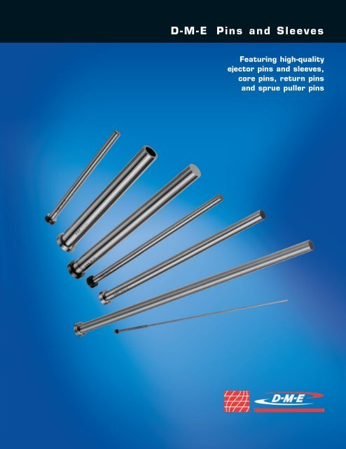
D-M-E<strong>Pins</strong> and SleevesFeaturing high-qualityejector pins and sleeves,core pins, return pinsand sprue puller pins
2INCHDIMENSIONS<strong>Pins</strong> and sleevesyou can depend on,shot after shot after shotTABLE OF CONTENTSEX Hotwork Ejector <strong>Pins</strong> . . . . . . . 4EX Hotwork Ejector <strong>Pins</strong>Shoulder and Small Diameter . . . 5THX Through-HardenedEjector <strong>Pins</strong> . . . . . . . . . . . . . . . . . . . 6CT (Close Tolerance) Through-Hardened Ejector <strong>Pins</strong> . . . . . . . . . 7S Ejector Sleeves . . . . . . . . . . . . . . 8SND Ejector Sleeves –Nitrided I.D. . . . . . . . . . . . . . . . . . . . 9C <strong>Core</strong> <strong>Pins</strong> . . . . . . . . . . . . . . . . . . . 10CX <strong>Core</strong> <strong>Pins</strong> . . . . . . . . . . . . . . . . . . 11PCL Performance <strong>Core</strong> <strong>Pins</strong> ® . . . 12Return <strong>Pins</strong> . . . . . . . . . . . . . . . . . . . 14Sprue Puller <strong>Pins</strong> . . . . . . . . . . . . . . 15Appendix A:Decimal Diameters Table . . . . . . . 16Appendix B:Hardness Conversion Tableand D-M-E Hardness Data . . . . . . 19Here’s why:Reason No. 1D-M-E Standard Ejector<strong>Pins</strong> and Sleevesand <strong>Core</strong> <strong>Pins</strong>are made ofthermal-shock resistinghotwork die steel (AISI H-13 type). This isa high-strength steel that has the physicalproperties needed to withstand thecontinuous punishment – the friction, the thermal andmechanical stresses – of plastics molding and die casting.Reason No. 2D-M-E has developed its own technology for hot-forging and some of its ownextremely sophisticated equipment. Totally automatic, this equipment controlstemperatures closely within 9°F (5°C), a major factor in producing uniform grainflow in D-M-E Ejector <strong>Pins</strong> and Sleeves and <strong>Core</strong> <strong>Pins</strong>, and in increasing theirdensity and tensile strength.Reason No. 3To give the strongest bond between the hard surface case and tough core,D-M-E uses a “new generation” nitriding process. Automated equipment monitorsand controls temperatures, processing time, and the ammonia atmosphere closelyand continuously – the only way to produce ejector pins and sleeves with highsurface hardness and good, tough cores.Reason No. 4After they’re finish ground and nitrided, D-M-E Ejector <strong>Pins</strong> and Sleeves aresent through an extra surface finishing operation. This gives them an exceptionallysmooth surface finish which greatly reduces friction and wear that can causetroublesome flash in ejector pin holes.Reason No. 5In addition to in-process inspections for surface hardness, case depth (ejector pinsonly), surface finish, and radius under the head, D-M-E checks and double checksits ejector and core pins for dimensional accuracy, concentricity and straightness.Reason No. 6D-M-E has the world’s most complete line of standard pins and sleeves – in stock –ready for immediate delivery to you.
3Pin and Sleeve Comparison ChartINCHDIMENSIONSWhile most of the information below is detailed on the individual pages to follow,it is provided here as a quick comparative reference.BODYHEADDESCRIPTION PAGE DIAMETER MATERIAL HARDNESS CONDITION CONDITIONEX Ejector <strong>Pins</strong> +.000 Surface 65-74 HRc NitridedEX2 (1/32) through EX8 (7/64) 5 –.001 H13 <strong>Core</strong> 35-43 HRc Minimum .001 deep AnnealedEX Ejector <strong>Pins</strong>EX9 (1/8) through EX32 (31/64) –.0003 Surface 65-74 HRc Nitridedlengths – 6" through 18" 4 –.0006 H13 <strong>Core</strong> 35-43 HRc Minimum .001 deep AnnealedEX Ejector <strong>Pins</strong>EX9 (1/8) through EX32 (31/64) –.0003 Surface 65-74 HRc Nitridedlengths – 25" through 36" 4 –.0008 H13 <strong>Core</strong> 35-43 HRc Minimum .001 deep AnnealedEX Ejector <strong>Pins</strong> –.0003 Surface 65-74 HRc NitridedEX33 (1/2) through EX47 (1") 4 –.0008 H13 <strong>Core</strong> 35-40 HRc Minimum .001 deep AnnealedTHX Ejector <strong>Pins</strong> +.000 Surface 65-74 HRc NitridedTHX03 (3/64) through THX08 (7/64) 6 –.001 H13 <strong>Core</strong> 50-55 HRc Minimum .001 deep AnnealedTHX Ejector <strong>Pins</strong>THX09 (1/8) through THX32 (31/64) –.0003 Surface 65-74 HRc Nitridedlengths – 6" through 18" 6 –.0006 H13 <strong>Core</strong> 50-55 HRc Minimum .001 deep AnnealedTHX Ejector <strong>Pins</strong> –.0003 Surface 65-74 HRc NitridedTHX33 (1/2) through THX47 (1") 6 –.0008 H13 <strong>Core</strong> 50-55 HRc Minimum .001 deep AnnealedCT Close Tolerance Ejector <strong>Pins</strong> –.0005CT5 (1/16) through CT11 (5/32) 7 –.0008 H13 <strong>Core</strong> 50-55 HRc Annealed+.000O.D. –.001+.0005 O.D. 65-74 HRc Nitrided O.D.S Ejector Sleeves 8 I.D. –.0000 H13 I.D. 30-35 HRc Minimum .001 deep Annealed+.000O.D. –.001+.0005 O.D. 65-74 HRc Nitrided O.D. & I.D.SND Nitrided I.D. Ejector Sleeves 9 I.D. –.0000 H13 I.D. 65-74 HRc Minimum .001 deep Annealed3" length – Hard+.001 6"-14" lengths –C <strong>Core</strong> <strong>Pins</strong> 10 –.000 H13 30-35 HRC Through Hardened Annealed3" length – Hard+.001 6"-14" lengths –CX High Hardness <strong>Core</strong> <strong>Pins</strong> 11 –.000 H13 50-55 HRc Through Hardened AnnealedMoldstarPCL Performance High +.001 150 ® 90-98BConductivity <strong>Core</strong> <strong>Pins</strong> 12, 13 –.000 (C18000) not applicable not applicable+.000 Surface 65-74 HRc NitridedReturn <strong>Pins</strong> 14 –.001 H13 <strong>Core</strong> 30-35 HRc Minimum .001 deep not applicable+.000 Surface 65-74 HRc NitridedSprue Puller <strong>Pins</strong> 15 –.001 H13 <strong>Core</strong> 35-43 HRc Minimum .001 deep Annealedwww.dme.net
4INCHDIMENSIONSD-M-E StandardEX Hotwork Ejector <strong>Pins</strong>HK1/32 R MAXIMUMMG**■■■■■Precision made of superior qualitythermal shock resisting hotwork die steelHot-forged heads provide uniform grainflow, higher tensile strengthOutside diameter nitrided to 65-74 HRchardness and finished to minimize wearHeads annealed for easy machiningCenterless ground and polished outer diameter**G H K M-6 M-10 M-14 M-18 M-25 M-36 M-45G** G** G** G**.005 .005 .005 .005ITEM HEAD HEAD G** OVER- G** OVER- G** OVER- G** OVER- G** G** G**PREFIX* PIN DIA DIA THICK STD SIZE STD SIZE STD SIZE STD SIZE STD STD STDEX9 1/8 (.125) 1/4 1/8EX10 9/64 (.140) 1/4 1/8EX11 5/32 (.156) 9/32 5/32EX12 11/64 (.171) 11/32 3/16EX13 3/16 (.187) 3/8 3/16EX14 13/64 (.203) 3/8 3/16EX15 7/32 (.218) 13/32 3/16EX16 15/64 (.234) 13/32 3/16EX17 1/4 (.250) 7/16 3/16EX18 17/64 (.265) 7/16 1/4EX19 9/32 (.281) 7/16 1/4EX20 19/64 (.296) 1/2 1/4EX21 5/16 (.312) 1/2 1/4EX22 21/64 (.328) 9/16 1/4EX23 11/32 (.343) 9/16 1/4EX24 23/64 (.359) 5/8 1/4EX25 3/8 (.375) 5/8 1/4EX26 25/64 (.390) 5/8 1/4EX27 13/32 (.406) 11/16 1/4EX28 27/64 (.421) 11/16 1/4EX29 7/16 (.437) 11/16 1/4EX30 29/64 (.453) 11/16 1/4EX31 15/32 (.468) 3/4 1/4EX32 31/64 (.484) 3/4 1/4EX33 1/2 (.500) 3/4 1/4EX34 17/32 (.531) 3/4 1/4EX35 9/16 (.562) 13/16 1/4EX37 5/8 (.625) 7/8 1/4EX39 11/16 (.687) 15/16 1/4EX41 3/4 (.750) 1” 1/4EX45 7/8 (.875) 1-1/8 1/4EX47 1” (1.000) 1-1/4 1/4–.0003= G Pin Diameter Tolerance: –.0006–.0003= G Pin Diameter Tolerance: –.0008 = Not Available, or Available as Special Only* To create Item Numbers for EX Ejector <strong>Pins</strong>:■ Combine Item Prefix with the letter “M” and the length (M dimension) desired. (e.g. EX25M14, EX33M10)■Add “OS” for .005" oversize diameters (e.g. EX25M14OS, EX33M10OS)U.S. 800-626-6653 • Canada 800-387-6600
D-M-E StandardEX Hotwork Ejector <strong>Pins</strong>SHOULDER AND SMALL DIAMETER5INCHDIMENSIONS1/32 R MAXIMUM 1/81/41/4 R1/8SM1/2" Shoulder Length (S Dimension)G M-6 M-10 M-14+.000G –.001■■■■■Precision made of superior qualitythermal shock resisting hotwork die steelHot-forged heads provide uniform grainflow, higher tensile strengthOutside diameter nitrided to 65-74 HRchardness and finished to minimize wearHeads annealed for easy machiningCenterless ground and polishedouter diameterITEM PIN G G .005 G G .005 GPREFIX* DIA STD OVERSIZE STD OVERSIZE STDEX2 1/32 (.031)EX3 3/64 (.046)EX5 1/16 (.062)EX6 5/64 (.078)EX7 3/32 (.093)EX8 7/64 (.109)NOTE: For 1/2" Shoulder Length, use suffix "SH" (see example below).2" Shoulder Length (S Dimension)G M-6 M-10 M-14ITEM PIN G G .005 G G .005 GPREFIX* DIA STD OVERSIZE STD OVERSIZE STDEX2 1/32 (.031)EX3 3/64 (.046)EX5 1/16 (.062)EX6 5/64 (.078)EX7 3/32 (.093)EX8 7/64 (.109)NOTE: For 2" Shoulder Length, no suffix should be used (see example below).= Not Available, or Available as Special Only+.0001/4 G–.0011/81/32 R MAXIMUMNo Shoulder (Small Diameter)G M-6 M-10GG.005 .005ITEM G OVER- G OVER-PREFIX* PIN DIA STD SIZE STD SIZEEX3 3/64 (.046)EX5 1/16 (.062)EX6 5/64 (.078)EX7 3/32 (.093)EX8 7/64 (.109)NOTE: For No Shoulder <strong>Pins</strong>, use suffix "NS" (see example below).M* To create Item Numbers for EX Shoulder andSmall Diameter Ejector <strong>Pins</strong>:■ Combine Item Prefix with the letter “M”and the length (M dimension) desired.■ Add a suffix to indicate the type of shoulder desired• For No Shoulder use the suffix NS(e.g. EX3M6NS, EX7M10NS)• For 1/2" Shoulder use the suffix 12SH(e.g. EX3M612SH, EX7M1012SH)• For 2" Shoulder no suffix should be used(e.g. EX3M6, EX7M10)■ Add “OS” for .005" oversize diameters(e.g. EX3M6NSOS, EX3M612SHOS, EX3M6OS)Quantity Discounts300 to 599 . . . . . . . . . Less 5%600 or more . . . . . . . . . Less 10%Discounts apply to Ejector <strong>Pins</strong>, <strong>Core</strong> <strong>Pins</strong>, Return <strong>Pins</strong>and Sprue Puller <strong>Pins</strong>. Standard sizes may be combinedon one order for quantity discounts.When ordering please specify:■ Item Number and Quantity■ Method of ShipmentSpecials Available.See “D-M-E Special <strong>Pins</strong> & Sleeves”www.dme.net
6INCHDIMENSIONSD-M-E StandardTHX Through-HardenedEjector <strong>Pins</strong>■Higher core hardness makes the THX pins ideal for usein die cast dies or other high temperature applicationsHNOTE:K1/32 R MAXIMUMMTHX pins are dimensionally identical tocomparable EX pins on pages 4 and 5.G**■■■■■<strong>Core</strong> hardness of 50-55 HRc minimizes nicking, dishingand bendingNon-chipping surface treatment of 65-74 HRc alleviates flashingAnnealed and finished heads permit easy machiningCenterless ground and polished outer diameterFinal finish minimizes wear and prolongs pin lifeG G** H K M-6 M-10 M-14 M-18PIN G G GDIA .005 .005 .005ITEM TOLER- HEAD HEAD G OVER- G OVER- G OVER- GPREFIX* PIN DIA ANCES DIA THICK STD SIZE STD SIZE STD SIZE STDTHX03 3/64 (.046)1/4 1/8THX05THX06THX07THX08THX09THX10THX11THX12THX13THX14THX15THX16THX17THX18THX19THX20THX21THX22THX23THX24THX25THX26THX27THX28THX29THX30THX31THX32THX33THX34THX35THX37THX39THX41THX45THX471/16 (.062)5/64 (.078)3/32 (.093)7/64 (.109)1/8 (.125)9/64 (.140)5/32 (.156)11/64 (.171)3/16 (.187)13/64 (.203)7/32 (.218)15/64 (.234)1/4 (.250)17/64 (.265)9/32 (.281)19/64 (.296)5/16 (.312)21/64 (.328)11/32 (.343)23/64 (.359)3/8 (.375)25/64 (.390)13/32 (.406)27/64 (.421)7/16 (.437)29/64 (.453)15/32 (.468)31/64 (.484)1/2 (.500)17/32 (.531)9/16 (.562)5/8 (.625)11/16 (.687)3/4 (.750)7/8 (.875)1” (1.000)+.000–.001–.0003–.0006–.0003–.00081/41/41/41/41/41/49/3211/323/83/813/3213/327/167/167/161/21/29/169/165/85/85/811/1611/1611/1611/163/43/43/43/413/167/815/1611-1/81-1/41/81/81/81/81/81/85/323/163/163/163/163/163/161/41/41/41/41/41/41/41/41/41/41/41/41/41/41/41/41/41/41/41/41/41/41/4= Not Available, or Available as Special Only* To createItem Numbersfor THXEjector <strong>Pins</strong>:■ Combine ItemPrefix withthe length(M dimension)desired■ Precede singledigit lengthswith a zero(e.g. THX2514,THX0906)■ Add “NS” (noshoulder) forItem Numbersup throughTHX08■ Add “OS” for.005" oversizediametersU.S. 800-626-6653 • Canada 800-387-6600
D-M-E StandardCT (Close Tolerance)Through-Hardened Ejector <strong>Pins</strong>7INCHDIMENSIONS■Higher core hardness makes the CT pins ideal for use in die castdies or other high temperature applications■■■■<strong>Core</strong> hardness of 50-55 HRc minimizes nicking, dishing and bendingAnnealed and finished heads permit easy machiningCenterless ground and polished outer diameterFinal finish minimizes wear and prolongs pin life1/32 R MAXIMUMNo ShoulderHKM = 6"–.0005G–.0008ITEM G H KPREFIX PIN HEAD HEADLength M = 6" DIA DIA THICKCT5M6NS 1/16 (.062)CT6M6NS 5/64 (.078)CT7M6NS 3/32 (.093) 1/4 1/8CT8M6NS 7/64 (.109)CT9M6 1/8 (.125)CT11M6 5/32 (.156) 9/32 5/32HK1/32 R MAXIMUM 1/81/4 RSM = 6"–.0005–.0008G2" Shoulder Length (S Dimension)ITEM G H KPREFIX PIN HEAD HEADLength M = 6" DIA DIA THICKCT5M6 1/16 (.062)CT6M6 5/64 (.078)CT7M6 3/32 (.093)1/4 1/8CT8M6 7/64 (.109)Quantity Discounts300 to 599 . . . . . . . . . Less 5%600 or more . . . . . . . . . Less 10%Discounts apply to Ejector <strong>Pins</strong>, <strong>Core</strong> <strong>Pins</strong>, Return <strong>Pins</strong>and Sprue Puller <strong>Pins</strong>. Standard sizes may be combinedon one order for quantity discounts.When ordering please specify:■ Item Number and Quantity■ Method of ShipmentSpecials Available.See “D-M-E Special <strong>Pins</strong> & Sleeves”www.dme.net
8INCHDIMENSIONSD-M-E StandardS Ejector SleevesEjector sleeve applicationsFigure A shows a typical EjectorSleeve application for plasticsmolding or die casting where thesleeve is used to eject the piece part.Figure B shows an applicationwhere the sleeve serves asa bushing for the ejector pin.This allows replacement withoutmachining if wear occurs. Thispractice is also desirable wherethe ejector pin is located betweencavity inserts. Using a sleeve asa bushing provides a full bearingdiameter for the pin.Fig. AEXPINFig. BNote generous lead-infor interference-free entry.EXPIN■■■■■■Precision made of superiorquality thermal shock resistinghotwork die steelHot-forged heads provideuniform grain flow, highertensile strengthOutside diameter nitridedto 65-74 HRc hardness andfinished to minimize wearCenterless ground andpolished outer diameterInside bearing diameteris 30-35 HRc hardness andfinished honedLead-in taper designed toallow interference-free entryof the ejector pin into the sleeveHB + 1/64K3/64 x 45º CHAMFER GENEROUS LEAD-IN+.000APPROXIMATELY 1º/SIDEG–.0011/32 R MAXIMUMM1/22-1/4**+.0005B–.0000* To create ItemNumbers forS Ejector Sleeves:■ Combine Item Prefixwith the letter“M” and the length(M dimension)desired. (e.g.S29M6, S25M10)H KITEM B G HEAD HEADPREFIX* I.D. O.D. DIA THICK M-3 M-4 M-5 M-6 M-7 M-8 M-9 M-10 M-11 M-12 M-14**S13 3/32 (.093) 3/16 (.187)**S15 1/8 (.125) 7/32 (.218)S17 5/32 (.156) 1/4 (.250)S21 3/16 (.187) 5/16 (.312)S23 7/32 (.218) 11/32 (.343)S25 1/4 (.250) 3/8 (.375)S29 5/16 (.312) 7/16 (.437)S33 3/8 (.375) 1/2 (.500)S37 7/16 (.437) 5/8 (.625)S39 1/2 (.500) 11/16 (.687)S41 9/16 (.562) 3/4 (.750)S45 5/8 (.625) 7/8 (.875)S47 3/4 (.750) 1 (1.000)**S13 and S15 have a 1-3/4 bearing length.3/813/327/161/29/165/811/163/47/815/1611-1/81-1/4= Not Available, or Available as Special Only3/163/163/161/41/41/41/41/41/41/41/41/41/4U.S. 800-626-6653 • Canada 800-387-6600
D-M-E StandardSND Ejector SleevesNITRIDED I.D.9INCHDIMENSIONSNote generous lead-infor interference-free entry.H3/64 x 45º CHAMFER GENEROUS LEAD-IN+.000APPROXIMATELY 1º/SIDEG–.001+.0005B–.0000B + 1/64■■■■K1/32 R MAXIMUMM1/22-1/4**Precision made of superior quality thermal shock resistinghotwork die steelHot-forged heads provide uniform grain flow, higher tensilestrengthOutside diameter nitrided to 65-74 HRc hardness andfinished to minimize wearCenterless ground and polished outer diameter■■■Inside bearing diameter is nitrided to 65-74 HRc hardnessand finished honedLead-in taper designed to allow interference-free entryof the ejector pin into the sleeveSND sleeve I.D. is nitrided for prolonged wear resistanceand improved lubricityH KITEM B G HEAD HEADPREFIX* I.D. O.D. DIA THICK M-3 M-4 M-5 M-6 M-7 M-8 M-9 M-10 M-11 M-12**SND13 3/32 (.093) 3/16 (.187) 3/8 3/16**SND15 1/8 (.125) 7/32 (.218) 13/32 3/16SND17 5/32 (.156) 1/4 (.250) 7/16 3/16SND21 3/16 (.187) 5/16 (.312) 1/2 1/4SND23 7/32 (.218) 11/32 (.343) 9/16 1/4SND25 1/4 (.250) 3/8 (.375) 5/8 1/4SND29 5/16 (.312) 7/16 (.437) 11/16 1/4SND33 3/8 (.375) 1/2 (.500) 3/4 1/4SND37 7/16 (.437) 5/8 (.625) 7/8 1/4SND39 1/2 (.500) 11/16 (.687) 15/16 1/4SND41 9/16 (.562) 3/4 (.750) 1 1/4SND45 5/8 (.625) 7/8 (.875) 1-1/8 1/4SND47 3/4 (.750) 1 (1.00) 1-1/4 1/4**SND13 and SND15 have a 1-3/4 bearing length.= Not Available, or Available as Special Only* To create Item Numbers for SND Ejector Sleeves:■ Combine Item Prefix with the length(M dimension) desired■ Precede single digit lengths with a zero(e.g. SND2506, SND1710)When ordering please specify:■ Item Number and Quantity■ Method of ShipmentQuantity Discounts300 to 599 . . . . . . . . . Less 5%600 or more . . . . . . . . . Less 10%Discounts apply to Ejector <strong>Pins</strong>, <strong>Core</strong> <strong>Pins</strong>, Return <strong>Pins</strong>and Sprue Puller <strong>Pins</strong>. Standard sizes may be combinedon one order for quantity discounts.Specials Available.See “D-M-E Special <strong>Pins</strong> & Sleeves”www.dme.net
10INCHDIMENSIONSD-M-E StandardC <strong>Core</strong> <strong>Pins</strong>Typical application1/32 R MAXIMUMH+.001G–.000KMHardness checking guidelines150 Kg. Cscale load.NORecommended Heat Treatmentto Annealed Heads(Air Hardening Hotwork Die Steel)For Cooling in Air:Heat to 1800˚F and cool.Tempering:Heat to 900˚-1100˚FFor Maximum Tempering:Heat to 980˚F and hold for 2 hours.NOTE: Avoid exposure to carburizingatmosphere or compounds.60 Kg. A scale load.YESIf checking hardness of core pins, do not use method“NO” above, since it will provide an inaccuratelylow reading. The preferred method is to stand the pinon its head and check the cut end using theA scale, 60 Kg. load as shown above.PRECAUTIONS:The cut end must be parallel to head end, withstem length of 2" minimum. Use cutting fluid toavoid overheating and localized annealing. Positionindentation in middle of pin diameter.■■■■■Precision made of superior quality hotwork die steelstandard hardness 30-35 HRcHeads are hot-forged for uniform grain flow, higher tensilestrength, then annealed to permit easier machining and stamping+.001"/–.000" tolerance on pin diameter ensures a close fitfor coring purposesPin body and head are finish groundCenterless ground and polished outer diameterG H KITEM PIN HEAD HEADPREFIX* DIA DIA THICK M-3 ** M-6 M-10 M-14C7 3/32 (.093) 1/4 1/8C8 7/64 (.109) 1/4 1/8C9 1/8 (.125) 1/4 1/8C10 9/64 (.140) 1/4 1/8C11 5/32 (.156) 9/32 5/32C12 11/64 (.171) 11/32 3/16C13 3/16 (.187) 3/8 3/16C14 13/64 (.203) 3/8 3/16C15 7/32 (.218) 13/32 3/16C17 1/4 (.250) 7/16 3/16C19 9/32 (.281) 7/16 1/4C21 5/16 (.312) 1/2 1/4C23 11/32 (.343) 9/16 1/4C25 3/8 (.375) 5/8 1/4C27 13/32 (.406) 11/16 1/4C29 7/16 (.437) 11/16 1/4C31 15/32 (.468) 3/4 1/4C33 1/2 (.500) 3/4 1/4C35 9/16 (.562) 13/16 1/4C37 5/8 (.625) 7/8 1/4C41 3/4 (.750) 1 1/4*See page 11 “To create Item Numbers”**Heads of 3"-length pins are not annealed. If annealed heads on 3"-lengthpins are required, they must be special ordered. (Alternately, you maypurchase 6" pins and cut to required length.)= Not Available, or Available as Special OnlyU.S. 800-626-6653 • Canada 800-387-6600
D-M-E StandardCX <strong>Core</strong> <strong>Pins</strong>HIGH HARDNESS11INCHDIMENSIONS1/32 R MAXIMUMH+.001G–.000KM■■■■■Precision made of superior quality hotwork die steelin high hardness 50-55 HRcHeads are hot-forged for uniform grain flow, higher tensilestrength, then annealed to permit easier machining and stamping+.001"/–.000" tolerance on pin diameter ensures a close fitfor coring purposesPin body and head are finish groundCenterless ground and liquid polishedG H KITEM PIN HEAD HEADPREFIX* DIA DIA THICK M-3 ** M-6 M-10 M-14CX7CX8CX9CX10CX11CX12CX13CX14CX15CX17CX19CX21CX23CX25CX27CX29CX31CX33CX35CX373/32 (.093)7/64 (.109)1/8 (.125)9/64 (.140)5/32 (.156)11/64 (.171)3/16 (.187)13/64 (.203)7/32 (.218)1/4 (.250)9/32 (.281)5/16 (.312)11/32 (.343)3/8 (.375)13/32 (.406)7/16 (.437)15/32 (.468)1/2 (.500)9/16 (.562)5/8 (.625)1/41/41/41/49/3211/323/83/813/327/167/161/29/165/811/1611/163/43/413/167/81/81/81/81/85/323/163/163/163/163/161/41/41/41/41/41/41/41/41/41/4CX41 3/4 (.750) 1 1/4**Heads of 3"-length pins are not annealed. If annealed heads on 3"-lengthpins are required, they must be special ordered. (Alternately, you maypurchase 6" pins and cut to required length.)= Not Available, or Available as Special Only* To create Item Numbers forC and CX <strong>Core</strong> <strong>Pins</strong>:■ Combine Item Prefix with the letter “M”and the length (M dimension) desired.(e.g. C33M10, C9M3, CX33M10, CX9M3)When ordering please specify:■ Item Number and Quantity■ Method of ShipmentQuantity Discounts300 to 599 . . . . . . . . . Less 5%600 or more . . . . . . . . . Less 10%Discounts apply to Ejector <strong>Pins</strong>, <strong>Core</strong> <strong>Pins</strong>,Return <strong>Pins</strong> and Sprue Puller <strong>Pins</strong>. Standardsizes may be combined on one order forquantity discounts.Specials Available.See “D-M-E Special<strong>Pins</strong> & Sleeves”www.dme.net
12INCHDIMENSIONSD-M-E StandardPCL Performance <strong>Core</strong> <strong>Pins</strong> ®HIGH-CONDUCTIVITY PINS■■■■■Reduces cycle timesTen times better conductivity than steelMoldstar 150 ® (C18000) beryllium-freecopper-based alloyHardness of 90-98 Rockwell BAvailable in 21 diameters and four lengthsD-M-E’s Performance <strong>Core</strong> <strong>Pins</strong> ® are precision made usinga high-strength, beryllium-free copper alloy, rather thantraditional steels used in core pins. This alloy provides severaladvantages, including better conductivity, increased strength,reduced wear and resistance to rusting. Performance <strong>Core</strong><strong>Pins</strong> are ideal for use in high-volume applications where partquality, fit and finish are critical.Reduced cycle timeIt is often difficult or expensive to adequately cool the areasurrounding the core pin in a mold, especially when moldingthick-walled parts. Depending on the design of the mold, itmay even be impossible to run water lines near the pin, thusgreatly increasing cycle times.The copper-based alloy used in Performance <strong>Core</strong> <strong>Pins</strong> cansignificantly reduce mold cycle times by increasing the rate ofheat transfer. The Performance <strong>Core</strong> Pin, when used in placeof traditional C- or CX-type pins, will provide up to 10 timesthe rate of heat transfer. Heat is transferred at twice the rateof pins made of a beryllium-copper alloy.In addition, the low-adhesion characteristics of the pins makepart ejection faster and easier. All of these advantages combineto reduce the overall cycle time and increase productivity.Improved part qualityThe excellent thermal diffusivity of the pins provide ahomogenous temperature profile throughout the core surface.Uniform temperatures result in reduced post-mold shrinkageand warpage, improving the quality of the part. Also, becauseof the low-adhesion characteristics of the pin, parts are notdamaged by adhesion to the pin during part ejection.Lower machining costsThe high thermal conductivity of Performance <strong>Core</strong> <strong>Pins</strong>reduces the need for complex cooling designs that canrequire hours of additional machining. Plus, the pins requireno additional heat treatment and can be machined usingconventional methods or EDM.Longer service lifePerformance <strong>Core</strong> <strong>Pins</strong> have a high resistance to thermalstress, wear and abrasion. This assures long life undervirtually any molding conditions. With appropriate alterationto pin diameter, they can be used in conjunction with standardejector sleeves. The dissimilar metals and compatible coefficientof friction will reduce metal-to-metal pick up and wear.Wide range of sizesPerformance <strong>Core</strong> <strong>Pins</strong> are available in 21 pin diametersfrom 3/32- to 3/4- and 3-, 6-, 14- or 20-inch lengths.Typical MoldAs shown in the pie chart, mold cooling comprisesthe largest part of the mold cycle. Performance<strong>Core</strong> <strong>Pins</strong> can significantly reduce this moldcooling portion to reduce overall cycle time!Mold Packing 10%Mold Filling 5%Mold Open 15%Mold Cooling 70%U.S. 800-626-6653 • Canada 800-387-6600
D-M-E StandardPCL Performance <strong>Core</strong> <strong>Pins</strong> ®HIGH-CONDUCTIVITY PINS13INCHDIMENSIONS■Reduces cycle timesH1/32 R MAXIMUM+.001G–.000■■Ten times better conductivitythan steelMoldstar 150 ® (C18000)beryllium-free copper-based alloy■Hardness of 90-98 Rockwell BKM■Available in 21 diametersand four lengthsG H KITEM PIN HEAD HEADPREFIX* DIA DIA THICK M-3 M-6 M-14 M-20PCL07 3/32 (.093) 1/4 1/8 .0937PCL09 1/8 (.125) 1/4 1/8 .1250PCL11 5/32 (.156) 9/32 5/32 .1562PCL12 11/64 (.171) 11/32 3/16 .1718PCL13 3/16 (.187) 3/8 3/16 .1875PCL14 13/64 (.203) 3/8 3/16 .2031PCL15 7/32 (.218) 13/32 3/16 .2187PCL17 1/4 (.250) 7/16 3/16 .2500PCL19 9/32 (.281) 7/16 1/4 .2812PCL21 5/16 (.312) 1/2 1/4 .3125PCL23 11/32 (.343) 9/16 1/4 .3437PCL25 3/8 (.375) 5/8 1/4 .3750PCL27 13/32 (.406) 11/16 1/4 .4062PCL29 7/16 (.437) 11/16 1/4 .4375PCL33 1/2 (.500) 3/4 1/4 .5000PCL35 9/16 (.562) 13/16 1/4 .5625PCL37 5/8 (.625) 7/8 1/4 .6250PCL41 3/4 (.750) 1 1/4 .7500= Not Available, or Available as Special OnlyPerformance <strong>Core</strong> <strong>Pins</strong> ® are produced by Performance Alloys & Services, Inc.under U.S. Patent Number 5,020,770.Issue date June 4, 1991.Foreign patents pending.■Specials are also availableupon request* To create Item Numbers forPCL Performance <strong>Core</strong> <strong>Pins</strong>:■ Combine Item Prefix with the length (M dimension)desired. (e.g. PCL2515, PCL0703)When ordering please specify:■ Item Number and Quantity■ Method of ShipmentQuantity Discounts300 to 599 . . . . . . . . . Less 5%600 or more . . . . . . . . . Less 10%Discounts apply to Ejector <strong>Pins</strong>, <strong>Core</strong> <strong>Pins</strong>, Return <strong>Pins</strong>and Sprue Puller <strong>Pins</strong>. Standard sizes may be combinedon one order for quantity discounts.Specials Available.See “D-M-E Special <strong>Pins</strong> & Sleeves”www.dme.net
14INCHDIMENSIONSD-M-E StandardReturn <strong>Pins</strong>■Precision made of superior quality thermalshock resisting hotwork die steelH1/41/32 R MAXIMUM+.000G–.001■■■Hot-forged heads provide uniform grainflow, higher tensile strengthOutside diameter nitrided to 65-74 HRchardness and finished to minimize wearCenterless ground and polishedouter diameterM1/2" Diameter SeriesG H MITEM PIN HEAD PINNUMBER DIA DIA LENGTH7410 3-9/167411 4-1/167412 +.0004-9/167413 .500 –.001 3/4 5-1/167414 5-9/167415 6-1/167416 6-9/16For longer lengths, use EX 33 Ejector <strong>Pins</strong> (page 4).5/8" Diameter SeriesG H MITEM PIN HEAD PINNUMBER DIA DIA LENGTH7510 4-1/167511 4-9/167512 5-1/167513 +.0005-9/167514 .625 –.001 7/8 6-1/167515 6-9/167516 7-1/167517 7-9/167518 8-1/16For longer lengths, use EX 37 Ejector <strong>Pins</strong> (page 4).3/4" Diameter SeriesG H MITEM PIN HEAD PINNUMBER DIA DIA LENGTH7610 4-15/167611 5-7/167612 5-15/167613 6-7/167614+.000.750 –.001 16-15/167615 7-7/167616 7-15/167617 8-7/167618 8-15/167619 9-7/16For longer lengths, use EX 41 Ejector <strong>Pins</strong> (page 4).U.S. 800-626-6653 • Canada 800-387-6600
D-M-E StandardSprue Puller <strong>Pins</strong>15INCHDIMENSIONS■Precision made of superior qualitythermal shock resisting hotwork die steelH1/32 R MAXIMUM+.000G–.001■■■Hot-forged heads provide uniformgrain flow, higher tensile strengthOutside diameter nitrided to 65-74 HRchardness and finished to minimize wearHeads annealed for easy machiningKM■Centerless ground and polishedouter diameter1/4" Diameter SeriesG H K MITEM PIN HEAD HEAD PINNUMBER DIA DIA THICK LENGTH7110 3-7/167111 3-15/167112 +.0004-7/167113 .250 –.001 7/16 3/16 4-15/167114 5-7/167115 5-15/167116 6-7/16For longer lengths, use EX 17 Ejector <strong>Pins</strong> (page 4).3/8" Diameter SeriesG H K MITEM PIN HEAD HEAD PINNUMBER DIA DIA THICK LENGTH7210 3-7/87211 4-3/87212 4-7/87213 5-3/87214 5-7/87215+.000.375 –.001 5/8 1/46-3/87216 6-7/87217 7-3/87218 7-7/87219 8-3/87220 8-7/87221 9-3/8For longer lengths, use EX 25 Ejector <strong>Pins</strong> (page 4).Quantity Discounts300 to 599 . . . . . . . . . Less 5%600 or more . . . . . . . . . Less 10%Discounts apply to Ejector <strong>Pins</strong>, <strong>Core</strong> <strong>Pins</strong>, Return <strong>Pins</strong>and Sprue Puller <strong>Pins</strong>. Standard sizes may be combinedon one order for quantity discounts.When ordering please specify:■ Item Number and Quantity■ Method of ShipmentSpecials Available.See “D-M-E Special <strong>Pins</strong> & Sleeves”www.dme.net
16AAPPENDIXDecimal Diameters TableThis composite table lists all D-M-E standard ejector and core pins by diameter from 1/32 to 32mm. Ejector pins from1/32 to 7/64 OS are available with 1/2" or 2" shoulder. Metric diameters, metric pin styles beyond those listed, and metricconversion information is available in the D-M-E Metric Components Catalog.FRACTIONORSTANDARDPIN METRIC ITEM LENGTHS: INCH ITEM LENGTHS: INCHDIA SIZE NUMBER OR MILLIMETER NUMBER OR MILLIMETER.0312.0312.0315.0354.0362.0362.0394.0394.0433.0469.0469.0469.0469.0472.0512.0519.0519.0519.0519.0551.0591.0591.0625.0625.0625.0625.0625.0625.06301/321/320.8 mm0.9 mm1/32 OS1/32 OS1 mm1 mm1.1 mm3/643/643/643/641.2 mm1.3 mm3/64 OS3/64 OS3/64 OS3/64 OS1.4 mm1.5 mm1.5 mm1/161/161/161/161/161/161.6 mmEX2-1/2 SHEX2 (2 SH)EC-0.8EC-0.9EX2-1/2 SH OSEX2 OS (2 SH)EC-1JFX-010EC-1.1EX3 NSEX3-1/2 SHEX3 (2 SH)THX03EC-1.2EC-1.3EX3 NS OSEX3-1/2 SH OSEX3 OS (2 SH)THX03 OSEC-1.4EC-1.5JFX-015EX5 NSEX5-1/2 SHEX5 (2 SH)THX05CT5 NSCT5 (2 SH)EC-1.66680,100,125,16080,100,125,1606680,100,125,160,200100,15080,100,125,16066,10,146,10,14680,100,125,16080,100,125,16061010680,100,125,16080,100,125,160,200,250100,150,20066,10,146,10,1466680,100,125,160,200————————————————————AH-1.5———————AH-1.6————————————————————100,125,160———————40,60,80,100,125,160,200.0669.0675.0675.0675.0675.0709.0748.0781.0781.07811.7 mm1/16 OS1/16 OS1/16 OS1/16 OS1.8 mm1.9 mm5/645/645/64EC-1.7EX5 NS OSEX5-1/2 SH OSEX5 OS (2 SH)THX05 OSEC-1.8EC-1.9EX6 NSEX6-1/2 SHEX6 (2 SH)80,100,125,160,20061010680,100,125,160,20080,100,125,160,2006,106,10,146,10,14————————————————————Description Of Pin Abbreviations:1/2 SH = 1/2" Shoulder2 SH = 2" ShoulderNS = No ShoulderTHX = No ShoulderOS = OversizeEjector <strong>Pins</strong> – Inch:EX = Hotwork Ejector <strong>Pins</strong>THX = Through-HardenedEjector <strong>Pins</strong>CT = Close-ToleranceThrough-HardenedEjector <strong>Pins</strong>FRACTIONORSTANDARDPIN METRIC ITEM LENGTHS: INCH ITEM LENGTHS: INCHDIA SIZE NUMBER OR MILLIMETER NUMBER OR MILLIMETER.0781.0781.0781.07875/645/645/642 mmTHX06CT6 NSCT6 (2 SH)E-26,1066160,250———AH-2———40,60,80,100,125,160,200,250.0787.0787.0831.0831.0831.0831.0866.0866.0938.0938.0938.0938.0938.0938.09842 mm2 mm5/64 OS5/64 OS5/64 OS5/64 OS2.2 mm2.2 mm3/323/323/323/323/323/322.5 mmEC-2JFX-020EX6 NS OSEX6-1/2 SH OSEX6 OS (2 SH)THX06 OSE-2.2EC-2.2EX7 NSEX7-1/2 SHEX7 (2 SH)THX07CT7 NSCT7 (2 SH)E-2.580,100,125,160,200,250100,150,200,2501010101016080,100,125,160,2006,106,10,146,10,146,1066160,250,315——————AH-2.2—C/CX-7—————AH-2.5——————100,125,160,200,250—3,6,10—————40,60,80,100,125,160,200,250.0984.0984.0988.0988.0988.0988.1063.1094.1094.1094.1094.1094.1094.1144.1144.1144.11812.5 mm2.5 mm3/32 OS3/32 OS3/32 OS3/32 OS2.7 mm7/647/647/647/647/647/647/64 OS7/64 OS7/64 OS3 mmEC-2.5JFX-025EX7 NS OSEX7-1/2 SH OSEX7 OS (2 SH)THX07 OSE-2.7EX8 NSEX8-1/2 SHEX8 (2 SH)THX08CT8 NSCT8 (2 SH)EX8 NS OSEX8-1/2 SH OSTHX08 OSE-3100,125,160,200,250100 THROUGH 6506,1010106,101606,106,10,146,106,1066101010160,250,315,400,500———————C/CX-8————————AH-3———————3,6,10————————40,60,80,100,125,160,200,250.1181.1253 mm1/8JFX-030EX9100 THROUGH 7006,10,14AHX-3C/CX-9100,200,3153,6,10,14Ejector <strong>Pins</strong> – Metric:E = Metric Ejector <strong>Pins</strong>EC = Metric Ejector <strong>Pins</strong>;ShoulderJFX = Metric Ejector <strong>Pins</strong>;JIS Standard<strong>Core</strong> <strong>Pins</strong> – Inch & Metric:C = <strong>Core</strong> <strong>Pins</strong>; Standard HardnessCX = <strong>Core</strong> <strong>Pins</strong>; High HardnessAHX = Metric <strong>Core</strong> <strong>Pins</strong>;Standard Through-HardenedAH = Metric <strong>Core</strong> <strong>Pins</strong>;High Through-HardenedU.S. 800-626-6653 • Canada 800-387-6600
17Decimal Diameters Table (continued)AAPPENDIXFRACTIONORSTANDARDPIN METRIC ITEM LENGTHS: INCH ITEM LENGTHS: INCHDIA SIZE NUMBER OR MILLIMETER NUMBER OR MILLIMETER.125.125.1260.130.130.1378.1378.1406.1406.1456.1456.1457.1562.1562.1562.1575.1575.1612.1612.1654.1719.1719.1769.1769.1772.1772.1875.1875.1925.1925.1969.1969.2031.2031.2047.2081.2081.2165.2165.2188.2188.2238.2238.2344.2344.2362.2362.23941/81/83.2 mm1/8 OS1/8 OS3.5 mm3.5 mm9/649/649/64 OS9/64 OS3.7 mm5/325/325/324 mm4 mm5/32 OS5/32 OS4.2 mm11/6411/6411/64 OS11/64 OS4.5 mm4.5 mm3/163/163/16 OS3/16 OS5 mm5 mm13/6413/645.2 mm13/64 OS13/64 OS5.5 mm5.5 mm7/327/327/32 OS7/32 OS15/6415/646 mm6 mm15/64 OSTHX09CT9E-3.2EX9 OSTHX09 OSE-3.5JFX-035EX10THX10EX10 OSTHX10 OSE-3.7EX11THX11CT11E-4JFX-040EX11 OSTHX11 OSE-4.2EX12THX12EX12 OSTHX12 OSE-4.5JFX-045EX13THX13EX13 OSTHX13 OSE-5JFX-050EX14THX14E-5.2EX14 OSTHX14 OSE-5.5JFX-055EX15THX15EX15 OSTHX15 OSEX16THX16E-6JFX-060EX16 OS6,10,146160,250,315,4006,10,146,10,14160,250,315,400100 THROUGH 75010,1410,141010160,250,315,4006,10,14,186,10,146160,250,315,400,500100 THROUGH 7506,10,146,10,14160,250,315,40010,1410,141010160,250,315,400100 THROUGH 7506,10,14,18,256,10,146,10,146,10,14160,250,315,400,500,630100 THROUGH 75010,1410,14160,250,315,400,5001010160,250,315,400,500100 THROUGH 6006,10,14,256,10,146,10,146,10,1410,1410,14160,250,315,400,500,630100 THROUGH 80010————AH-3.2 100,125,160,200,250————AH-3.5 100,125,160,200,250——C/CX-103,6,10,14——————AH-3.7 100,125,160,200,250C/CX-113,6,10,14————AH-4 40,60,80,100,125,160,200,250,315AHX-4 100,200,315————AH-4.2C/CX-12 100,125,160,200,250,315—3,6,10,14————AH-4.5—— 100,125,160,200C/CX-13——3,6,10,14————AH-5—AHX-5 40,60,80,100,125,160,200,250,315C/CX-14 100,200,315—3,6,10,14AH-5.2—— 100,125,160,200,250,315————AH-5.5—C/CX-15 100,125,160,200—3,6,10,14————————AH-6—AHX-6 40,60,80,100,125,160,200,250,315——100,200,315—FRACTIONORSTANDARDPIN METRIC ITEM LENGTHS: INCH ITEM LENGTHS: INCHDIA SIZE NUMBER OR MILLIMETER NUMBER OR MILLIMETER.2394.244115/64 OS6.2 mmTHX16 OSE-6.210160,250,315,400,500—AH-6.2—100,125,160,200,250,315.250.250.255.255.2559.2559.2656.2656.2706.2706.2756.2756.2812.2812.2862.2862.2969.2969.3019.3019.3125.3125.31501/41/41/4 OS1/4 OS6.5 mm6.5 mm17/6417/6417/64 OS17/64 OS7 mm7 mm9/329/329/32 OS9/32 OS19/6419/6419/64 OS19/64 OS5/165/168 mmEX17THX17EX17 OSTHX17 OSE-6.5JFX-065EX18THX18EX18 OSTHX18 OSE-7JFX-070EX19THX19EX19 OSTHX19 OSEX20THX20EX20 OSTHX20 OSEX21THX21E-86,10,14,18,256,10,14,186,10,14,186,10,14160,250,315,400,500100 THROUGH 60010,14,2510,141010160,250,315,400,500100 THROUGH 8006,10,14,18,256,10,146,10,146,10,1410,1410,1410106,10,14,18,256,10,14,18160,250,315,400,C/CX-17———AH-6.5—————AH-7—C/CX-19———————C/CX-21—AH-83,6,10,14———100,125,160,200,250—————100,125,160,200,250—3,6,10,14———————3,6,10,14—60,80,100,125,160,500,630,800200,250,315.3150.3175.3175.3228.3281.3281.3331.3331.3346.3438.3438.3488.3488.3543.3543.3594.3594.3644.3644.375.375.380.380.39068 mm5/16 OS5/16 OS8.2 mm21/6421/6421/64 OS21/64 OS8.5 mm11/3211/3211/32 OS11/32 OS9 mm9 mm23/6423/6423/64 OS23/64 OS3/83/83/8 OS3/8 OS25/64JFX-080EX21 OSTHX21 OSE-8.2EX22THX22EX22 OSTHX22 OSE-8.5EX23THX23EX23 OSTHX23 OSE-9JFX-090EX24THX24EX24 OSTHX24 OSEX25THX25EX25 OSTHX25 OSEX26100 THROUGH 12006,10,14,186,10,14160,250,315,400,500,63010,14,2510,141010160,250,315,400,500,6306,10,14,256,10,1410,1410,14160,250,315,400,500,630100 THROUGH 50010,1410,1410106,10,14,18,25,366,10,14,186,10,14,186,10,1410AHX-8——AH-8.2—————C/CX-23—————————C/CX-25————100,200,315——100,125,160,200,250,315—————3,6,10,14—————————3,6,10,14————www.dme.net
18AAPPENDIXDecimal Diameters Table (continued)FRACTIONORSTANDARDPIN METRIC ITEM LENGTHS: INCH ITEM LENGTHS: INCHDIA SIZE NUMBER OR MILLIMETER NUMBER OR MILLIMETER.3906.393725/6410 mmTHX26E-1010160,250,315,400,—AH-10—80,100,125,160,500,630,800,1000200,250,315.3937.3956.3956.4016.4062.4062.4112.4112.4134.4219.4219.4269.4269.4331.4375.4375.4425.4425.4531.4531.4581.4581.4688.4688.4724.4724.4738.4803.4844.4844.4894.4894.492110 mm25/64 OS25/64 OS10.2 mm13/3213/3213/32 OS13/32 OS10.5 mm27/6427/6427/64 OS27/64 OS11 mm7/167/167/16 OS7/16 OS29/6429/6429/64 OS29/64 OS15/3215/3212 mm12 mm15/32 OS12.2 mm31/6431/6431/64 OS31/64 OS12.5 mmJFX-100EX26 OSTHX26 OSE-10.2EX27THX27EX27 OSTHX27 OSE-10.5EX28THX28EX28 OSTHX28 OSE-11EX29THX29EX29 OSTHX29 OSEX30THX30EX30 OSTHX30 OSEX31THX31EX-12JFX-120EX31 OSE-12.2EX32THX32EX32 OSTHX32 OSE-12.5100 THROUGH 12001010160,250,315,400,500,6306,10,14,18,256,10,1410,1410,14160,250,315,400,500,63010101010160,250,315,400,500,6306,10,14,18,25,366,10,146,10,146,10,14101010106,10,14,18,256,10,14160,250,315,400,500,630100 THROUGH 120010160,250,315,40010,1410,141010160,250,315,400,500,630,800AHX-10——AH-10.2C/CX-27———AH-10.5—————C/CX-29———————C/CX-31—AH-12AHX-12——————AH-12.5100,200,315——100,125,160,200,250,3153,6,10,14———100,125,160,200,250,315—————3,6,10,14———————3,6,10,14—80,100,125,160,200,250,315100,200,315——————100,125,160,200,250,315FRACTIONORSTANDARDPIN METRIC ITEM LENGTHS: INCH ITEM LENGTHS: INCHDIA SIZE NUMBER OR MILLIMETER NUMBER OR MILLIMETER.500.500.505.505.5312.5312.55121/21/21/2 OS1/2 OS17/3217/3214 mmEX33THX33EX33 OSTHX33 OSEX34THX34E-146,10,14,18,25,366,10,14,1810,1410,146,10,146,10,14160,250,315,400,C/CX-33—————AH-143,6,10,14—————100,125,160,200,500,630,800,1000250,315.5625.5625.5906.625.625.6299.6875.6875.7087.750.750.7874.875.875.98431.0001.0001.25989/169/1615 mm5/85/816 mm11/1611/1618 mm3/43/420 mm7/87/825 mm1"1"32 mmEX35THX35JFX-150EX37THX37E-16EX39THX39E-18EX41THX41E-20EX45THX45E-25EX47THX47E-326,10,14,18,256,10,14100 THROUGH 12006,10,14,18,25,366,10,14,18160,250,315,400,500,630,800,10006,10,14,18,256,10,14160,250,315,400,500,6306,10,14,18,25,366,10,14,18160,250,315,400,500,630,800,10006,10,14,18,256,10,14250,315,400,500,630,800,10006,10,14,18,25,3610,14,18250,315,400,500,630,800,1000C/CX-35——C/CX-37—AH-16———C/CX-41————————6,10,14——6,10,14—100,125,160,200,250,315———6,10,14————————Description Of Pin Abbreviations:1/2 SH = 1/2" Shoulder2 SH = 2" ShoulderNS = No ShoulderTHX = No ShoulderOS = OversizeEjector <strong>Pins</strong> – Inch:EX = Hotwork Ejector <strong>Pins</strong>THX = Through-HardenedEjector <strong>Pins</strong>CT = Close-ToleranceThrough-HardenedEjector <strong>Pins</strong>Ejector <strong>Pins</strong> – Metric:E = Metric Ejector <strong>Pins</strong>EC = Metric Ejector <strong>Pins</strong>;ShoulderJFX = Metric Ejector <strong>Pins</strong>;JIS Standard<strong>Core</strong> <strong>Pins</strong> – Inch & Metric:C = <strong>Core</strong> <strong>Pins</strong>; Standard HardnessCX = <strong>Core</strong> <strong>Pins</strong>; High HardnessAHX = Metric <strong>Core</strong> <strong>Pins</strong>;Standard Through-HardenedAH = Metric <strong>Core</strong> <strong>Pins</strong>;High Through-HardenedU.S. 800-626-6653 • Canada 800-387-6600
Hardness Conversion Tableand D-M-E Hardness Data19BAPPENDIXThe values shown are based on the Wilson Conversion Chart.Hardness ROCKWELL SHORERange of C B 15-N Sclero- TENSILED-M-E BRINELL 150 Kg 100 Kg Super- scope STRENGTHSTANDARDS 3000 Kg load load ficial No. (Approx. p.s.i.)80 96.578 96.076 95.574 95.0EX, THXEJECTORPINSSurfaceHardnessCXCORE PINSTHX, CTEJECTORPINS<strong>Core</strong>Hardness72 94.570 94.069 93.5 9667 93.0 9566 92.5 9265 92.0 9164 8863 91.5 8762 91.0 8561 90.5 83614 60 90.0 81600 59 89.5 80587 58 78573 57 89.0 76560 56 88.5 75547 55 88.0 74 301,000534 54 87.5 72 291,000522 53 87.0 71 282,000509 52 86.5 69 273,000496 51 86.0 68 264,000484 50 85.5 67 255,000472 49 85.0 66 246,000460 48 84.5 64 237,000448 47 84.0 63 229,000437 46 83.5 62 221,000426 45 83.0 60 214,000415 44 82.5 58 207,000404 43 82.0 57 200,000393 42 81.5 56 194,000382 41 81.0 55 188,000372 40 80.5 54 182,000Hardness ROCKWELL SHORERange of C B 15-N Sclero- TENSILED-M-E BRINELL 150 Kg 100 Kg Super- scope STRENGTHSTANDARDS 3000 Kg load load ficial No. (Approx. p.s.i.)362 39 80.0 52 177,000352 38 79.5 51 171,000342 37 79.0 50 166,000332 36 78.5 49 162,000322 35 78.0 48 157,000CCOREPINSPCLPERFORMANCECORE PINS313 34 77.0 47 153,000305 33 76.5 46 148,000297 32 76.0 44 148,000290 31 75.5 43 140,000283 30 75.0 42 136,000276 29 74.5 41 132,000270 28 74.0 – 129,000265 27 73.5 40 126,000260 26 72.5 38 123,000255 25 72.0 – 120,000250 24 71.5 37 117,000245 23 100 71.0 36 115,000240 22 99 70.5 35 112,000235 20 98 69.5 34 108,000230 20 98 69.5 34 108,000201 94 31 98,000197 93 30 95,000192 92 29 93,000187 91 – 90,000183 90 28 89,000179 89 27 87,000174 88 27 87,000170 87 26 83,000167 86 – 81,000163 85 25 79,000156 83 24 76,000149 81 23 73,000143 79 22 71,000137 76 21 67,000131 74 – 65,000www.dme.net
World HeadquartersD-M-E Company29111 Stephenson HighwayMadison Heights, MI 48071800-626-6653 toll-free tel248-398-6000 tel888-808-4363 toll-free faxwww.dme.net webinfo@dme.net e-mailD-M-E of Canada, Ltd.6210 Northwest DriveMississauga, OntarioCanada L4V 1J6800-387-6600 toll-free tel905-677-6370 tel800-461-9965 toll-free faxD-M-E EuropeD-M-E Belgium C.V.B.A.Industriepark NoordB-2800 Mechelen, Belgium32-15-215011 tel32-15-218235 faxsales@dmeeu.com e-mailLitho in U.S.A.PS-11M-04/05


