DTC602-NA Installation Instructions Rev B .pdf - Philips Lighting ...
DTC602-NA Installation Instructions Rev B .pdf - Philips Lighting ...
DTC602-NA Installation Instructions Rev B .pdf - Philips Lighting ...

Create successful ePaper yourself
Turn your PDF publications into a flip-book with our unique Google optimized e-Paper software.
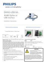
…………………………………………………....…………………………………………………………<strong>DTC602</strong>-<strong>NA</strong>Timeclock<strong>Installation</strong> <strong>Instructions</strong>…………………………………………………....…………………………………………………………Electrical ConnectionsConnect Data Cable in a ‘Daisy Chain’Data Cable Permanent ConnectionsMounting Location – Install in a dry, well-ventilated location indoors in an officecleanarea.Data Cable Connecting MethodThe recommended connecting method is to ‘daisy chain’ devices (i.e., starting atthe first device, then looping in and out of devices, with a single cable terminatingat the last device. There should not be any spurs or stubs, and only the first andlast device should terminate 1 cable, all other devices should terminate 2 cables).Devices may be wired in any order. Data cable is Class 2 and must be separatedfrom line (mains) conductors per NEC. A data cable that is connected to anenergized device is live. Do not cut or terminate live data cables. For longer cableruns, the Data Cable segregation from any Mains Cables of 12” is recommendedto minimize noise coupling. If the Data Cable has to cross over any Mains Cables,it should do so at a 90° angle.Data Cable Termination1. Strip off between 1” and 2-1/4” of outer jacket.2. Cut shield (foil or braid) flush to outer jacket. DO NOT cut drain wire.3. Fit 1/16” heat-shrink tubing over drain wire, leaving 1/8” of wire exposedfor termination.4. Fit 1” length of 3/8” heat-shrink tubing over the entire cable. Position itso that 3/4” of its length is over cable jacket, and 1/4” of its length is overloose connectors.5. Strip 1/8” of insulation from each of the conductors.6. Terminate conductors on the terminal block.7. Shrink remaining heat-shrink tubing.8. Apply the appropriate ID label to the cable at the end of the outer heatshrinktubing.Recommended cable typesBelden: #1502RBelden: #1502PShielded or Screened cable is recommended for DyNet networks.UTP Cat 5 cables are acceptable under certain conditions and ifinstalled in conduit. See DyNet Cable Guidelines.Cable color codingBlack: groundRed: 24VBlue/white pair: Blue for DATA+ White for DATA-WARNINGThis is a Class 2 device and must only beconnected to Class 2 wiring.To reduce the risk of fire or electric shockand to avoid damage to the unit, beforeinstallation or servicing, disconnect network& device power at circuit breakers or removefuses.It is recommended that an electrician perform this installation.Do not expose this device to rain or moisture. Connect the cableshield to the provided shield termination on a device connectionport. If no shield termination is provided on a device, connect thecable shield to equipment grounding conductor of the supplyingbranch circuit(s). <strong>Installation</strong>, programming and maintenancemust be carried out by qualified personnel.
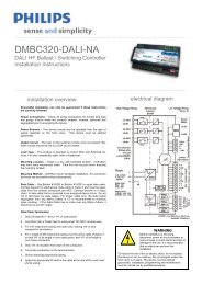
…………………………………………………....…………………………………………………………<strong>Installation</strong> Steps1. Unpack unit and inspect for any signs of shipping damage.2. Install NEMA approved 3-gang wallbox or mounting box of appropriate type (3-gang type not supplied).Minimum internal wall box dimensions: 5.5 (w) x 3.0 (h) x 1.9 inches (d)3. Prior to cable termination ensure power is disconnected from the DyNet network4. Terminate and connect network cable.5. Insert timeclock into the wall box or mounting box. Secure with four supplied mounting screws. Do not over-tighten.…………………………………………………....…………………………………………………………Mounting DimensionsThis device complies with Part 15 of the FCCRules. Operation is subject to the followingtwo conditions:(1) This device may not cause harmfulinterferenceand(2) This device must accept any interferencereceived, including interference that maycause undesired operation.This Class A digital apparatus complies withCanadian ICES-003…………………………………………………....…………………………………………………………Product SpecificationsDyNet DC Loadmax. 35mA@24VDCData portsRS485 DyNetTerminals5-way removable screw terminal ,1 X 14 AWG or 2 X 18AWG max conductor sizeUser Controls4.3” x 1.3” back lit LCD display12 button LCD transport keys12 button numeric keypadClockInternal ControlsPC time clock with battery backupAuto screen dimmingComplianceFCC, RoHS , ICES Compliant (see statements)Operating Environment365 day clock ConstructionBattery back upSunrise/Sunset tracking32º to 122ºF (0º to 50ºC) ambient temp0% to 90% RH non condensingAccessories3-gang wall box, min. internal dimensions 5.5 x 3.0 x 1.9inches. Recommended to use Raco #697 or equivalent.0.06” stainless steel faceplate/bodyDimensionsAutomatic daylight saving adjustment H 4.5” x W 6.5” x D 1.0”250 timed events, 64 tasksMemoryAll data stored in long-life EEPROMWeightPacked weight 0.5 lb……………………………………………………………………………………………………………………………………………………<strong>DTC602</strong>-<strong>NA</strong> <strong>Installation</strong> <strong>Instructions</strong> <strong>Rev</strong> B. Oct 7, 2010. Specifications subject to change without notice. All rights reserved.Dynalite, DyNet and associated logos are the registered trademarks of <strong>Philips</strong> Dynalite. Not to be reproduced without permission.Manufactured by WMGD Pty Ltd (ABN 33 097 246 921) Unit 6, 691 Gardeners Road, Mascot, NSW 2020, AustraliaWeb: lightolier.com E-Mail: controls.support@philips.com. Tel: 1-800-526-2731.