DUCTGARD - Gilberts (Blackpool)
DUCTGARD - Gilberts (Blackpool)
DUCTGARD - Gilberts (Blackpool)
- No tags were found...

You also want an ePaper? Increase the reach of your titles
YUMPU automatically turns print PDFs into web optimized ePapers that Google loves.
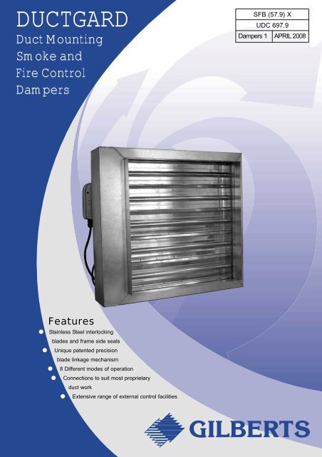
<strong>DUCTGARD</strong>Duct MountingSmoke andFire ControlDampersSFB (57.9) XUDC 697.9Dampers 1 APRIL 2008Features● Stainless Steel interlockingblades and frame side seals● Unique patented precisionblade linkage mechanism● 8 Different modes of operation● Connections to suit most proprietaryduct work● Extensive range of external control facilitiesGILBERTS
I n t r o d u<strong>Gilberts</strong> Ductgard presents an‘engineered’ range of combinedsmoke and fire dampers suitablefor use in all types of HVACductwork.Developed from our well provendoor mounting smokegarddamper, over 40 years ofengineering experience in theindustry and considerableingenuity has been applied in thedesign and construction of thisproduct to produce a damper ofhigh efficiency, reliability, durabilityand ease of use.
The Gilbert’s 2007 Ductgardpresents a re-engineered range ofcombined fire and smoke damperssuitable for use in HVAC ductworksystems.c t i o nDeveloped from a well proven, triedand tested damper, considerableingenuity and manufacturingexpertise has been further appliedto produce a robust, effective,competitive unit that is easy toinstall and maintain.The unit is designed to fit within alltypes of ductwork at its juction witha fire barrier wall, where it can befixed directly in or immediatelyadjacent to the building structure inboth the horizontal and verticalpositions.A choice of 8 different modes ofoperation are available providing forboth a manual and fully automaticoperation.All units comprise of an air-tightgalvanised casing (DW144 Class CSpecification) with stainless steelinterlocking blades and frame sideseals, which provides a four-hourfire rated assembly. Sizes rangefrom 200 x 200 upto a maximum of1000 x 1000 in one unit.Dampers over this size are suppliedin multiple units. Intermediary sizesare available as standard uponrequest.Mode Description Page5A Fully automatic electronic 24v DC opening with fail safe spring 4closure via 72°C electro thermal link release5B Fully automatic electronic 240v AC opening with fail safe spring 4closure via 72°C electro thermal link release6A Fully automatic electronic 24v DC closure with fail safe spring 4opening via 72°C electro thermal link release6B Fully automatic electronic 240v AC closure with fail safe spring 4opening via 72°C electro thermal link release9A Fully automatic motorised 24v AC/DC opening and fail safe 5spring closure via 72°C electro thermal link release9B Fully automatic motorised 240v AC opening and fail safe spring 5closure via 72°C electro thermal link release10A Fully automatic motorised 24v AC/DC closure and fail safe 5spring opening via 72°C electro thermal link release10B Fully automatic motorised 240v AC closure and fail safe 5spring opening via 72°C electro thermal link releaseANCILLARY FEATURE OPTIONSControl Mode Options■ REMOTE CONTROL PANELS - HARD WIRED & MULTIPLEX■ REMOTE STATUS INDICATION AND TEST PANELS■ VOLT FREE CONTACTS FOR REMOTE ELECTRICAL/BLADE STATUS INDICATION■ HEVAC BUILD IN AND DRY WALL FIXING FRAMES■ ACCESS PANELS2
FeaturesStainless SteelEdge SealsThese provide effectivebarriers to cold smokepenetration and allow theblades to expand underfire conditions minimisingleakage at all timesConnections to suit mostproprietary ductwork flangesand spigots.1.2mm welded duct to damperextension fitted as standard tohouse control options, offersDW142 Class C specification.8 different modes ofoperationInterlocking BladeOperationThe Stainless SteelBlades featured on theDuctgard units,incorporate a fishtail edgedetail which, with the helpof the precision singlerack operation, enablesthe blades to close andinterlock extremely tightly.This provides a tough,effective screen againstsmoke and flames for itsmaximum 4 hour rating.Inter-ConnectingMechanismAll Ductgard units aredriven using a unique,patented, interconnectingrack mechanism asillustrated. Thisintrinsically simplemechanism has beeningenuitively applied tothe damper and itscharacteristics ensure thatall units can operaterepeatedly with faultlessprecision. Added benefitsinclude reliability,durability, speed and lowtorque operatingconditions.3
Mode 5DescriptionMode 5 is a fully automatic type of smoke andfire damper and operates on the basis of failsafe closure with automatic reset. It has beendesigned to close in smoke and fire conditionsupon signal from a fire detection system or inthe event of an electro thermal fusible linkseparating at a pre-determined temperature(72°C standard).OperationMode 5 is fitted with a square drive spring returnmotor which will hold the damper open for aslong as the supply voltage is available.Interruption of this supply will cause controlleddamper closure by way of the motors springreturn operation. In addition however, thedamper is also fitted with an electro thermalfusible link which will separate at a predeterminedtemperature (72°C standard) andclose the damper irrespective of motor position.All Mode 5 units are also fitted with a controlbox which is situated on the dampers ductworkextension and houses the integral PCB, statusindication L.E.D. and test facility. The test keyfacility allows local checks to be made on thedamper operation.The L.E.D., provides the following diagnosticchecks:-GREEN DISPLAY:- Power supply ON, unit set.RED DISPLAY:- Power supply ON, but unit infail safe mode.NO DISPLAY:- Power supply failure, unit in failsafe mode.The control box also provides an interface forremote status indication, smoke detectors andRCP control (see page 11 and 12).Control OptionsA - 24v DC Power SupplyB - 240v AC Power SupplyRe-Set ProcedureProvided the fusible link is intact and the remoteor local test facility is not being utilised thedamper will automatically reset after aninterruption of the supply voltage. The motor willtake approximately 80 seconds to fully open thedamper.The LED indicator and test facility are housed ina control panel mounted on the ductworkconnection sleeve. Fully assembled prior todespatch they require only the external electricalwiring connections to be made on site.OPTIONAL FEATURES■ A RANGE OF MULTIPLEX OR ELECTRO-MECHANICAL CONTROLPANELS■ REMOTE, ELECTRICAL BLADE STATUS INDICATION PANELS■ HEVAC INSTALLATION FRAME/DRY WALL FIXING FRAME■ ACCESS PANELMode 6Mode 6 performs in exactly the same manner asthe Mode 5 except that the operation is reversedand the unit is fail safe open. The motor sets theunit in the closed position and the unit will onlyopen in the event of a signal from the firedetection system, separation of the thermalfusible link or operation of the key test facility.Ordering procedure: Back cover.4
Mode 9DescriptionMode 9 is a fully automatic type of smoke andfire damper and operates on the basis of failsafe closure with automatic reset. It has beendesigned to close in smoke and fire conditionsupon a failure of the supply voltage to the motoror in the event of an electro thermal fusible linkseparating at a pre-determined temperature(72°C standard). Volt free microswitches areincluded as standard.OperationMode 9 is fitted with a spring return square drivemotor which will hold the damper open for aslong, as the supply voltage is available.Interruption of this supply will cause controlleddamper closure by way of the motors springreturn operation. In addition however, thedamper is fitted with an electro thermal fusiblelink which will fail at a pre-determinedtemperature (72°C standard) and close thedamper irrespective of the status of the motor.An integral test pushbutton on the electrothermal fuse housing allows for the local testingof the damper operation.Motor Control OptionsA: 24V AC or DC supply.B: 240V AC supply.Note: All options are complete with positionmicroswitches as standard.Re-set ProcedureProvided the fusible link is intact the damper willautomatically reset after an interruption of thesupply voltage to the motor. The motor will takeapproximately 80 seconds to open the damper.The spring return motor and terminal box (iffitted) are mounted on the ductwork connectionsleeve. Fully assembled prior to despatch theyrequire only the external electrical connectionsto be made.Mode 10Mode 10 performs in exactly the same manneras the Mode 9 except that the operation isreversed and the unit is fail safe open. Themotor sets the unit in the full closed position andthe unit will only open in the event of a aninterruption of the supply voltage to the motor orseparation of the thermal fusible link.Ordering procedure: Back coverOPTIONAL FEATURES■ A RANGE OF ELECTRO-MECHANICAL CONTROL PANELS■ VOLT FREE CONTACTS FOR REMOTE INTERFACE■ REMOTE, ELECTRICAL BLADE STATUS INDICATION PANELS■ DAMPER MOUNTING TERMINAL BOX FOR MICROSWITCHAND/OR MOTOR CABLING■ HEVAC INSTALLATION FRAME/DRY WALL FIXING FRAME■ ACCESS PANELS5
DimensionalDataDampers OnlyDampers with Installation FramesSquare and Rectangular Spigots . . .Ref SSmaller and intermediate sizes available41List Width - 393Dim 'A'12140List Width + 19925 25Units supplied with 40mmdeep spigots for rivettingor self tapping intoductwork system.List Size Range200 - 1000 WIDE in 50mmincrements100 - 1000 HIGH in 100mmincrementsDim 'A'Modes,9,10 140Above with terminalbox 240Modes 5,6 240Circular Spigots . . . . . . . . . . . . . . . . .Ref CMode 9 & 1041140List Diameter - 3 93121Smaller and intermediate sizes availableList Diameter + 19950 2525Units supplied with 40mmdeep circular spigots forrivetting or self tapping intoductwork system.List Size Range200 - 1000 Diameter in 100mmincrementsFor other circular duct sizes, overallsizes as next size up standard size.For example, 315 duct has 312spigots and 432 high casing25Circular Spigots . . . . . . . . . . . . . . .Ref CMode 1, 2, 5 & 641List Diameter - 39350 50242 121Smaller and intermediate sizes availableList Diameter + 199252541List Height + 147412541List Height + 14741252541List Height - 3List Height + 1474125Units supplied with 40mm deepcircular spigots for rivetting orself tapping into ductworksystem.List Size Range200 - 1000 Diameter in 100mmincrementsFor other circular duct sizes, overallsizes as next size up standard size.For example, 315 duct has 312spigots and 432 high casing256
DimensionalData41Dampers OnlyOval Spigots . . . . . . . . . . . . . . . . . .Ref OList Diameter - 39350 50242 121Dampers with Installation FramesSmaller and intermediate sizes availableList Width + 19925 2541List Height - 3List Height + 1474125Units supplied with 40mm deepoval spigots for rivetting or selftapping into ductwork system.List Size Range300 - 1000 Wide in 50mmincrements200 - 900 High in 100mmincrementsFor other oval duct sizes, overallsizes as next size up standard size.For example, 350 high duct has347 high spigots and432 high casingSPECIFIC TOLERANCES AVAILABLE ON REQUEST. DIMENSIONAL DATA APPLIES TO UNITS SIZED IN 50mm WIDTH/HEIGHTINCREMENTS ONLY. INTERMEDIATE DIMENSIONS AVAILABLE.25MultipleAssembliesFor Installation where a damper largerthan 1000mm x 1000mm is requiredmultiple unit assemblies can be provided.These can take the form of either a twopack horizontal or vertical assembly or afull 4 pack assembly (i.e. two doubleassemblies). Each module of theassembly is provided with its own controlunit and fusible link.Note:Before installation of any multipleassembly proposed arrangements shouldbe agreed with the relevant authority.Multiple Square and Rectangular Spigots . . . . . . . . . . . . . . . . . .Ref S93 List Width - 393Dim A 12140List Width + 25125 25Typical4 packassembly41List Height - 3List Height + 1474125Units supplied with40mm deepspigots for rivetting orself tapping intoductwork system.Dim 'A'Modes, 9,10 - 140(240 with terminal box)Modes 5,6 - 240List Size Range1100 - 2100 WIDE in50mm increments1100 - 2100 HIGH in100mm incrementsFor intermediate sizesrefer to head office25TypicalDoubleassembly7
InstallationFramesHEVAC Installation Frame HVC 6/5/85The installation frame is designed to be factory assembledon to a fire damper. This frame will under fire conditionsallow the damper to expand without distortion. Upstandflange webs with fixing tabs built into the surroundingstructure ensure that the complete assembly will be retainedwithin the structural opening.A factory assembled installation frame may be provided andfitted to a double module assembly not exceeding an overallsize of 1524 x 1016mm (split on the larger dimension).Adjacent frame assemblies must be separated by builderswork of a minimum distance of 225mm (between installationframe upstand flanges unless approval has been previouslyobtained from the appropriate authority).Where two fire dampers, or two double module assembliesare mounted in series to form a factory assembled four hourunit, each damper or double module assembly comprisingthe unit shall be provided with its own installation frame soas to allow each individual damper or double moduleassembly to expand under fire conditions.The work shall be carried out to the satisfaction of theappropriate authority which in inner London, will be theDistrict Surveyor. Any deviation must have similar approval.Building Ties for SecuringUnit to StructureHORIZONTAL FLOOR MOUNTINGCorner Joints permitinternal expansion ofInstallation FrameExpansion Cleats betweenFrame and DamperDry Wall Partition InstallationFor dry wall partitions an alternative fixing method isillustrated. This method comprises of a fixed anglearrangement. The plate is secured to the structure by fixingbolts. Note:- This method of installation must be approved tothe satisfaction of the appropriate authority. Approvedalternative methods of installation are available upon request.16swg FixingAngle75mm8
Wiring DataModes 5/6The wiring data below provides all the information necessary to effect correct connection of all Ductgard units in their variousmodes and control options as well as instructions for including extra feature options. Removal of the lid on the dampercontrol box provides access to an internal terminal block for the following wiring connections. If in doubt ask.Modes 5&6 Control Option AModes 5&6 Control Option BStandard Wiring Arrangement with Remote Indicator Option- + + -R GLN- + + -R G24VDC +300MA Supply -switch or voltfree contacts240VAC9VA SupplyO G RO G RStandard Wiring Arrangement with Smokeduct Detector and Remote Indicator- R G++-240V AC9VA Supply- R GL N ++-24V DC300MA Supplyswitch or voltfree contacts1 41 422NC NO CNC NO CO G R4 wiresmokedetectorO G R4 wiresmokedetectorStandard Wiring Arrangement with Remote Control Panel (RCP)- + + -R GLN- + + -R G24VDC +300MA Supply -240VAC9VA SupplyO G RSOO G RSOremotecontrolpanelKEY - ALL OPTIONS Link Wiring by <strong>Gilberts</strong> External Wiring by OthersNote:DC Power Supply to have a 3v AC maximum ripple.Wiring shownonly required when local indication at damper is needed whenreleased remotely.Do not loop wire under Smoke Detector terminals - break wire run to provide system supervision.An integral LED is included in the damper control panel to indicate blade position of damper. A key is also providedfor local testingAlternative wiring/control options are available, refer to Head Office if variations required.9
Modes 9/10Mode 9 and 10 Ductgards in this option are normally controlled, by a remote switch on the Motor Supply.Note: To interface with <strong>Gilberts</strong> remote indicators it is easier to switch the negative rather than the positive.Control Option A- +1 2MControl Option B- +1 2MS1 - S2 made when damperclosesS4 - S6 made when damperopenS1 S2 S3 S4 S5 S65° 80°S1 S2 S3 S4 S5 S65° 80°24 V WIRING DIAGRAMPower Supply 24V AC + -20%50/60 Hz24V DC + -20%Current Rating 380mA AC maxPOWER CONSUMPTIONOpening5 wattsHolding2.5 watts240V WIRING DIAGRAMPower Supply 240V AC +15% -10%50/60 Hz240V AC +10% 50HzCurrent Rating 200mA AC maxPOWER CONSUMPTIONOpeningapprox 6 wattsHoldingapprox 3 wattsModes 9/10AddressableMode 9 and 10 Ductgards in this option are interfaced with our Gardex Controlleras described on Page 11. Motoriseddampers are fitted with the Belimo BLF-T range as standard. Other actuators are available upon request.2 Core ScreenedCommunication CableBelimo Damper MotorM240V 50HZFused Spur(option 24V DC)L N E1 2 3 4 5 6N L 1 2 3 4 5 6 + + - - S SDCM Damper Control Module10
ControlSystems<strong>Gilberts</strong> offer a wide choice of hard wired and multiplex controlled systems to meet the challenge of effective fire andsmoke control monitoring.Available as stand alone, or suitable for interfacing or incorporating with building management or fire/smoke controlsystems designs, the range includes four simple off the shelf packages through to bespoke designs to satisfy the mostdemanding criteria.Gardex (Modes 9/10 Options Only) Multiplex SystemThe Gardex system has been designed to reduce the cost of electrical wiring installations and satisfy the most complex ofcontrol changes. Up to 126 dampers can share the same 2 wire communication line to transmit information to and from thecentral controller.FeaturesHousing -Metal wall mounted enclosure complete with a clear hinged lockable front cover and lower cablingchamber. Protection rating IP55Keyboard and Display - Directory command programming via arrow keys and 2 line x 40 character LCD display areFault reporting -provided as an operator interface.Faults are identified on the LCD display and the controller can be interrogated to determine thenature of the fault and its location.CENTRAL CONTROLLERTYPICAL OPTIONAL FEATURES■ MIMIC AND DAMPER STATUS INDICATORLIGHTSPOWER ONSYSTEM FAULTFIRE COMMANDFAULTACKNOWLEDGEDRESETACKNOWLEDGELAMP TESTPROGRAMGardexController■ INTEGRAL FIREMANS INTERFACE SWITCH■ MECHANICAL FAN CONTROL■ LINE ISOLATION■ REMOTE ALARM INTERFACE500mm1 2 3 4 5 6 7 8 9 10 11 12 13 14 15 16 17 18 19 20SMOKE DAMPER STATUS INDICATION21 22 23 24 25 26 27 28 29 30 31 32 33 34 35 36 37 38 39 40SMOKE DAMPER STATUS INDICATION41 42 43 44 45 46 47 48 49 50 51 52 53 54 55 56 57 58 59 60SMOKE DAMPER STATUS INDICATION61 62 63 64 65 66 67 68 69 70 71 72 73 74 75 76 77 78 79 80SMOKE DAMPER STATUS INDICATION400mmBottom Entry GlandPlate 300x90mm (approx)DamperIndicatorDamperIndicatorExpanderField Stations (DCM)Available as an integral part of the damper, or as aseparate enclosure, the addressable module has beendesigned to provide independent operation of individualor groups of dampers in accordance with a preprogrammedlogic sequence of events.Individual dampers are controlled and have there statusconstantly monitored by the module in response tosignals from the pre-programmed controller. Maximumlength of communications 2km. In the event ofcommunications failure dampers assume failsafeposition.BespokeControlPanelsThese are available in a number of configurations and aredesigned and manufactured to suit individual specificrequirements. The electro-mechanical control/monitoringpanels are based on IP55 wall mounting enclosures, whichcan be provided to include such features as:■ FIREMANS/BMS INTERFACE30mm75mmSET TRIP GREEN SET■ MULTI ZONE CONTROL & DAMPER STATUSRED TRIPPEDINDICATIONS■ UPS■ VOLT FREE CONTROLS FOR REMOTEINDICATION OR ALARMKeyswitchor push buttonRCP Modes 5 & 6 OnlySO-G-R-O-Please contact Head Office to discuss specific requirements.11
AncillaryItems<strong>Gilberts</strong> range of ancillary Items have been designed for use in conjunction with both the Ductgard and Smokegard models.Purpose built for straightforward connection and compatibility they offer a number of useful services.Remote Indicators/Master Monitors<strong>Gilberts</strong> remote indicator panels can be linked todamper Modes 5 and 6 and will provide remoteindication of the status of one or more dampers.Ref:- RT1 (1 damper)MM1-12 (upto 12 dampers)Larger Panels available upon request100mmUNIT No.AIIFA No.GREEN LIGHTSYSTEM SETRED LIGHTSYSTEM TRIPPEDFROM<strong>DUCTGARD</strong>YELLOWBLUE-VE DCORGOUTLINE OF PCBNOTE: When damper is open yellow is +VEWhen damper is closed blue is +VE76mm35mmMaster MonitorA more advanced form of remote indication isavailable with a master monitor. This unitprovides remote indication for the status of up to12 individual dampers.Ref:- MM1-12** dependant on number of dampers on thesystem240mm240mmMaster MonitorMaster MonitorGILBERTSGILBERTS240mm87mmFROM<strong>DUCTGARD</strong>FROM<strong>DUCTGARD</strong>YELLOWYELLOWBLUEBLUE -VE DC-VE DCOROGRGOROGRUP TO 12 GPCBs IN 1MASTER UP TO 12 MONITOR PCBs IN 1MASTER MONITORNOTE: When damper is open yellow is +VEWhen damper is closed blue is +VENOTE: When damper is open yellow is +VEWhen damper is closed blue is +VE240mm87mmStandard Power SupplyStandard power supplies are available in twosizes to suit up to 6 or up to 12 dampers. Theyprovide conversion from 240v AC input to asmooth and stabilised 24v DC output.Ref:- G6 = 6 UNIT OUTPUTG12 = 12 UNIT OUTPUTG6R = 6 UNIT OUTPUT + RELAYG12R = 12 UNIT OUTPUT + RELAY240mmPOWER SUPPLYUNITTYPE G12MAINS INPUT 240 V.A.C.lOUTPUT TO DAMPER 24 V.A.C.lWARNING - ISOLATEMAINS SUPPLY BEFOREENTERINGGILBERTSMAIN POWER SUPPLY240v ACENL24v DC POWER OUT240mm87mmUninterruptible Power SupplyUninterruptible power supplies operating on a240v AC input provide a smooth 24v DC output topower up to 12 dampers. Unlike standard powersupplies however, in the event of a power failure,there will be an automatic changeover to in-builtbatteries without tripping the dampers providingcontinued power for a period of up to 1 hour.Ref:- UPS6 = 6 UNIT OUTPUTUPS12 = 12 UNIT OUTPUTUPS6R = 6 UNIT OUTPUT + RELAYUPS12R = 12 UNIT OUTPUT + RELAY350mmUNINTERUPTABLEPOWER SUPPLYCELLS:- 27.6v DC MAX: TEST YEARLYMAINS INPUT: 240v ACOUTPUT TO DAMPERS 24v DCGILBERTSONONTHIS UNIT IS DESIGNED TO SUPPLY UPTO 12 DAMPERS FOR UP TO 1 HOURTHE INTERNAL DRY-FIT CELLS DO NOT REQUIRE SERVICE ORELECTROLYTE LEVEL TOPPING-UP. WARNING: TAKE CARE WHENINSIDE THIS UNIT CELLS GIVE 100+ AMPS IF SHORTED OUTMAIN POWER SUPPLY240v ACENL24v DC POWER OUT240mm87mmSmoke DetectorsSmoke Detectors are available for in duct or ceiling mounting and can link directly into Modes5 & 6 or the output relay of the Power Supply units. Detectors are 24v DC Ionisation typeRef: In-duct 4 wire - SD34 wire - SD212
Test DataFire TestsAll fire tests were conducted by the WarringtonResearch Centre to BS476 Part 20 1987.This standard describes the performance ofstructural elements under fire conditions. It wasdecided to mount the unit in the face of a 3m sq.vertical furnace, and subject it to the testdescribed.Test DescriptionThe test specimen was fixed to a brick wall builtwithin a framed lined with refractory concrete atthe test laboratory. This frame was thenmounted such that the complete assemblyformed the front vertical face of the gas firedfurnace. The furnace was provided withthermocouples arranged such that they wereevenly distributed over the exposed face of thetest construction and with their hot junction100m from the nearest part of the construction.Test ResultThe damper assembly operated satisfactorilyand retained its integrity for the 240 minuteheating period, during which time there were notany significant gaps in or around the assemblyto permit the passage of flames.Air Velocity AgainstPressure DropThe graph opposite has been formulated to givean indication of the pressure drop expectedthrough a fully open damper in relation to ductair velocity.Differential Pressure (Pa)Temperature - Deg C10009876543210098765432109876543Standard Time - Temperature Curve Of BS476 Part 20 198712001100100090080070060050040030020010000 20 40 60 80 100120 140160 180200 220 240Time - minutesSpecified Furnace Temperature2Airflow Blade Leakage AgainstDifferential PressureThe graph opposite illustrates the maximumleakage obtainable when the damper is in a fullyclosed position under ambient temperatureconditions.DuctgardLeakage underFire Test(Unit Tested 1m 2Face Area)Differential Pressure (Pa)1100009876543210009876543210098765432 3 4 5 6 7 8 9 10 2 3 4 5 6 7 8 9100Air Velocity M/S21312 3 4 5 6 7 8 9 10 2 3 4 5 6 7 8 9100Leakage Rate L/S
Operation &MaintenanceInstructionsOperating and MaintenanceInstructionsAll Ductgard units are tested beforeleaving the factory but should be testoperated prior to commissioning toensure correct operation. Quick andeasy testing and reset procedures foreach operational mode are detailed ontheir respective data pages in thisbrochure. In addition to their initial testhowever, being a fire safety product, itis also recommended that the units aretest operated regularly thereafter . Testfrequency will depend upon thedamper environment but, in theabsence of any other information, amaximum interval of 6 months isrecommended. In addition an annualvisual inspection is also advisable topermit cleaning and removal of anyairborne contaminants which mayaffect the dampers operation.NoteFor safety the damper blades shouldbe closed on Modes 5,9, and open onmodes 6,10, before personallyapproaching them forinspection/cleaning.Since the drive, linkage, motors andelectronic components on the ductgardunits are ‘sealed for life’ there shouldbe no requirement for periodicmaintenance and spares are notnormally required. Items such as resetlevers and test keys however can bemisplaced over time. In this eventreplacements are readily available fromHead Office.Trouble-ShootingAll Ductgard units are both inspected and tested before leaving our premises. Manufactured using maintenance free ‘sealedfor life’ components there is no reason why they should not reach site in full working order and continue to function wheninstalled providing that our fitting and wiring instructions have been adhered to. In the event of operational difficulties pleasecontact our Head Office for on-line guidance and advice.Telephone: (01253) 766911Ductgard units carry a full 1 year warranty from the date of delivery for all parts and labour.<strong>Gilberts</strong>Damper,Smoke andFire ControlRangeSmokegardDoor, Wall and PartitionMounted Smoke and FireDampersSeries 52Smoke Evacuation DamperSeries 50/51Fire Smoke DampersFiregardCurtain Fire DampersAirgardVolume ControlDampersSeries RDIris Duct Damper14
OrderingSpecificationSERIES:TYPE:Square/Rectangular:..............SCircular...................................COval........................................ODUC S 450 x 200 9 A IF TB FC/NC AP 15SIZE (mm width x Height or Dia)MODE: 5, 6, 9 & 10CONTROL OPTION: A or BINSTALLATION FRAME OPTION:Standard................................IFDry Wall Partition...................DFCABLE TERMINATION BOX...TB(Modes 9,10)CONDITION MICROSWITCHOPTIONS:Fail Safe...................................FCNormal......................................NCFailsafe + Normal...............FC/NC(Modes 5 & 6 only.Standard on Mode 9 & 10)ACCESS PANEL..........................APNUMBER REQUIREDSTANDARD POWER SUPPLIES:6 Way.....................................................................G66 Way c/w output relay...........................................G6R12 Way...................................................................G1212 Way c/w/ output relay........................................G12RUNINTERRUPTIBLEPOWER SUPPLIES:6 Way.....................................................................UPS66 Way c/w output relay...........................................UPS6R12 Way...................................................................UPS1212 Way c/w/ output relay........................................UPS12RREMOTE INDICATORS:Single unit.........................................................SR1MASTER MONITOR:1 - 12 unit..........................................................SMM1 -12plus per damperSMOKE DETECTORS:24V DC wire ionisation......................................SD2Outer CasingComponents for the outer casing aremanufactured from 1.2mm galvanisedsteel. BS EN 10142:1991:FEP02Gformed into sections of averagedimensions 120 x 50mm with spigotends for connection to systemductwork. Outer casing sections arefully welded.Inner CassetteComponents to form the inner cassetteon all four sides are from 1.5mmgalvanised mild steel. Components areformed into a channel section of size120mm x 50mm. The inner casing ismechanically joined at the corners Thevertical components contain holes forblade spindles. The horizontalcomponents are complete with returnedge channels for retaining the top andbottom seals.Damper BladesThe damper blades are made from0.45mm thick (.018”) BS 1449 stainlesssteel. Blades are formed into a hollowsectional profile. The blade ends areformed into individual circular driveshafts and located on brass bushesthrough the side channels.Side seals of 0.25mm stainless (as perblade specification) are formed andpierced to accept blade drive shaftsand are assembled between frame andblade ends. Top and bottom seals aremanufactured in the same material butare retained on top and bottom framesby returned channels fixed on in theframe inner surface.The blades are actuated by a 2mmthick x 58mm steel channel located inthe side frame and acting on steelpinions attached to blade ends. Therack and pinions are galvansied andare contained in the side frame.Half gears as rack specification transferthe sideways rack movement to circularblade drive shafts. A drive bar movesthe rack up or down and is either handor motor controlled via a electro thermalfuse.ContactGILBERTSHead Office and WorksGILBERTS (BLACKPOOL) LTDGilair Works, Clifton Road,<strong>Blackpool</strong>.Lancashire FY4 4QT.Telephone: (01253) 766911Fax: (01253) 767941e-mail: sales@gilbertsblackpool.comWeb: www.gilbertsblackpool.com<strong>Gilberts</strong> (<strong>Blackpool</strong>) Ltd reserve the right to alter the specification without notice. The information contained in this leaflet is correct at time of going to press © 2007.