DUCTGARD - Gilberts (Blackpool)
DUCTGARD - Gilberts (Blackpool)
DUCTGARD - Gilberts (Blackpool)
- No tags were found...

Create successful ePaper yourself
Turn your PDF publications into a flip-book with our unique Google optimized e-Paper software.
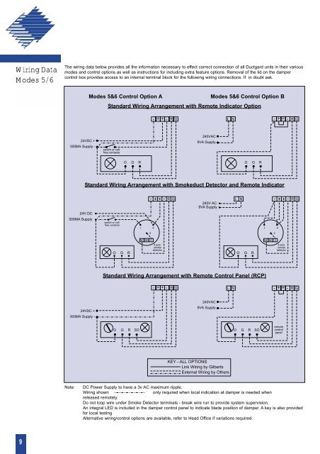
Wiring DataModes 5/6The wiring data below provides all the information necessary to effect correct connection of all Ductgard units in their variousmodes and control options as well as instructions for including extra feature options. Removal of the lid on the dampercontrol box provides access to an internal terminal block for the following wiring connections. If in doubt ask.Modes 5&6 Control Option AModes 5&6 Control Option BStandard Wiring Arrangement with Remote Indicator Option- + + -R GLN- + + -R G24VDC +300MA Supply -switch or voltfree contacts240VAC9VA SupplyO G RO G RStandard Wiring Arrangement with Smokeduct Detector and Remote Indicator- R G++-240V AC9VA Supply- R GL N ++-24V DC300MA Supplyswitch or voltfree contacts1 41 422NC NO CNC NO CO G R4 wiresmokedetectorO G R4 wiresmokedetectorStandard Wiring Arrangement with Remote Control Panel (RCP)- + + -R GLN- + + -R G24VDC +300MA Supply -240VAC9VA SupplyO G RSOO G RSOremotecontrolpanelKEY - ALL OPTIONS Link Wiring by <strong>Gilberts</strong> External Wiring by OthersNote:DC Power Supply to have a 3v AC maximum ripple.Wiring shownonly required when local indication at damper is needed whenreleased remotely.Do not loop wire under Smoke Detector terminals - break wire run to provide system supervision.An integral LED is included in the damper control panel to indicate blade position of damper. A key is also providedfor local testingAlternative wiring/control options are available, refer to Head Office if variations required.9