burndy unitap - Womack Electric Supply Company
burndy unitap - Womack Electric Supply Company
burndy unitap - Womack Electric Supply Company

Create successful ePaper yourself
Turn your PDF publications into a flip-book with our unique Google optimized e-Paper software.
What’s NewBlack UNITAPMultiple Tap Connectors . . . . . . . . . . . . . . . . . . . . . . . . . . . . A-51YH4434Copper CRIMPIT . . . . . . . . . . . . . . . . . . . . . . . . . . C-108 - C-110Clear CoversClear H-Tap Flame Retardant Cover . . . . . . . . . . . . . . . . . . .C-112BURNDYWeld Mesh and FillGrounding, Personal Safety Mats,Equipotential Planes, Signal Reference Grid . . . . . D-83 - D-88Type B Flexible Copper Braidis now UL/CSA Listed . . . . . . . . . . . . . . . . . . . . Sections D and G4-POINT Y81KFTDieless HYPRESSHydraulic Hand Operated Crimping Tool . . . . . . . . . . . . . N-27PATRIOT ® PAT750XT-18VHydraulic Self-Contained Battery Operated12 Ton Crimping Tool . . . . . . . . . . . . . . . . . . . . . . . . . . . . . N-29PATRIOT ® 4-POINT PAT81KFT-18VHydraulic Self-Contained Battery Operated6-Ton Crimping Tool . . . . . . . . . . . . . . . . . . . . . . . . . . . . . N-31PATRIOT ® IN-LINE PATMD6-14VBattery Actuated Hydraulic Self-Contained6-Ton Crimping Tool . . . . . . . . . . . . . . . . . . . . . . . . . . . . . N-324-POINT Y81KFTMBH6-Ton Remote Power Operated Dieless Hydraulic Tool . . . . N-46RHCC129ACSRRemote Power Operated Hydraulic Cable Cutter . . . . . . . . . N-51RHCC245CUALRemote Power Operated Hydraulic Cable Cutter . . . . . . . . . N-52Throughout the catalog you will notice blue highlighted items;these are the most frequently ordered BURNDY ® Products.
MASTER INDEXABCDEFGHIJKLMNOMECHANICALConnectors secured by nuts, bolts or allen head devicesSMALL COMPRESSIONConnectors secured by indent or circumferential crimpsMEDIUM AND LARGE COMPRESSIONConnectors secured by indent or circumferential crimpsGROUNDINGIrreversable Compression Grounding System and Mechanical GroundingOVERHEADPower distribution connectors both Mechanical and Compression used on pole applicationsWEJTAPPower actuated connection systemsSUBSTATIONPower distribution connectors for tube cable and bus applicationsALUMINUM WELDMENTSExtra High Voltage devicesNETWORK UNDERGROUNDPower distribution connectors for underground applicationsURD UNDERGROUNDPower distribution connectors for underground applicationsCABLE TIESUNIRAP cable tiesHARDWARENuts, Bolts and Washers of various metalsACCESSORIESOxide Inhibitors Markers and Terminal BlocksTOOLINGHand-Held, Mechanical Hydraulic and PneumaticREFERENCESDies, Connectors Charts and General Information....... ............ .................... ....................................... ......... ................................ ............. ...... ... .................................................. .................................................. ................................... ............................................................. .................. .................................................................... ............ ...................................................
MASTER INDEX............................................... ........................................... ......................... ....................................................................................................................... ....... ............. ........................ .......... .... ................. ............................................................................................................................................................................................................................................................................. ............................................................................................................................................................................................................................................................................. .............................................................................. ...................................................... ...................... ..............................................................................................................ABCDEFGHIJKLMNO
BURNDY ® ProductsMechanicalTABLE OF CONTENTSTypes KS, KS-3 & SC. . . A-4Types VA, VVA . . . . . . . A-21Type BIPC . . . . . . . . . . A-36A-1Type KSU . . . . . . . . . . . . A-5Type HFB-P1 . . . . . . . . A-22SPEC-BLOK . . . . A-37, A-38Type KSA . . . . . . . . . . . . A-6Types KVS, KVSU . . . . . A-7Types KVSW, KVS-A . . . A-8Type QPX. . . . . . . . . . . . A-9Type QPX-Y . . . . . . . . . A-10Type KPA . . . . . . . . . . . A-11Type KPA-UP . . . . . . . . A-12Type KLU . . . . . . . . . . . A-13Type HFB-N . . . . . . . . . A-23Types KA-U, KKA-U . . . A-24Type K2A-U . . . . . . . . . A-25Types K3A-U, KK3A-U. . . . . . . . . . . . . . A-26, A-27Types K4A-U, KK4A,K11A-U, K21A, K22A . A-28Type KAU-KIT . . . . . . . A-29Type AMS. . . . . . . . . . . A-30SPEC-BLOKPLATFORMS . . . . . . . A-39Types BDA, BDB,BDC . . . . . . . . . A-41, A-42,A-43, A-44, A-45Types BIT, BISR . . . . . . A-46Type BIBS . . . . . . . . . . A-47Type BIBD . . . . . . . . . . A-48Types BIBS-MT,BIBD-MT . . . . . . . . . . A-49Types KA, EA . . . . . . . . A-14Type AGSKIT . . . . . . . . A-31Type BISR-DB . . . . . . . A-50Types BGBL, CL50-1 . . A-15Type UGSKIT . . . . . . . . A-31Type 1PL . . . . . . . . . . . A-51Types QA, QQA . . . . . . A-16Type UGSKIT8 . . . . . . . A-32Types Q2A, Q3A. . . . . . A-17Type UGS350ULDB . . . A-32Complies with NFPA 78-86 Ordinary Structures.Complies with NFPA 78-86 Heavy Duty Stacks(order: LD for Lead Plating for Heavy Duty Stacksapplications).Types QB, Q2B . . . . . . A-18Type QGFL. . . . . . . . . . A-33Types QDA & QR . . . . . A-19Type FCB . . . . . . . . . . . A-34Types VT, E-C-G. . . . . . A-20Types KPU-AC,UCU-AC . . . . . . . . . . . A-35
BURNDY ® ProductsMechanicalLIGHTNING PROTECTION INFO.A-2Basic rules for selection are:1 Must be like material to the conductor(Flexitap out due to steel bolts!).2. Two bolts to ground rod — minimum.3 Cable to cable connections can beanything — one bolt, two bolt, compression,etc.4 Cable to steel structure must have 8square inch contact with steel.5. Heavy duty stacks — mechanical only.6. On all connectors with heavy duty stackrating, we must offer 1/16" thick lead platingas an option. Reason is closest 25 ft.to stack opening must use lead coatedproduct.Complies with NFPA 78-86 OrdinaryStructures.Complies with NFPA 78-86 HeavyDuty Stacks(order: LD for Lead Plating for HeavyDuty Stack applications)SPECIAL FEATURESOther features are also available for productslisted in price book such as undrilled orspecial drilling, 45° or 90° pad angles, bellingfor extra flexible cable, smooth or specialthreaded studs, special labeling or packaging,extra long braid, and nuclear certification.REFER TO FACTORY.ALL OTHERSREFER TO FACTORY1-800-346-4175
BURNDY ® ProductsMechanicalREVOLUTIONARYBURNDY DESIGNMEETS STRICT UL486B STANDARDSA-3. . . and puts the bite onaluminum connectionsforever!For use on all combinations• Aluminum to aluminum• Aluminum to copper• Copper to copperUnique ‘‘bite and grip’’ TRITAPSERVIT ® contact delivers safe,long-term reliability—evenwithout scratch brushing . . .without oxide inhibitingcompounds.†PatentedAvailable in sizes from #10 through 500 kcmil.Spacer provides built-inseparation to retardgalvanic corrosion.Triangular edges biteinto cable to breakthrough surface oxides...provide low contact resistance....produces gas tight seal.Tin-plated contactsurface inhibits oxideformation.Special heat-treated hard,aluminum alloy.Anti-galling, high efficiencythreaded components result in highcontact force. Easily installed usingstandard, everyday wrenches.†When used in NEC applications of insulated cables only.
BURNDY ® ProductsMechanicalTYPES KS & KS-3A-4SERVIT ®For Copper, CopperweldCompact, high strength, high copper alloySERVIT ® split-bolt has free-running threadsand easy to grip wrench flats. Highly resistantto season cracking and corrosion, theSERVIT ® provides maximum pressure andassures a secure connection on all combinationsof run and tap conductors. Type KS-3accommodates 3 maximum size conductors.CONDUCTORCOPPER COPPERWELD ▲MIN.TAPRECOMMENDEDCATALOG CROSS RANGE FOR EQUAL WITH MAXIMUM RUN AND TAP TIGHTENINGNUMBER FLATS L W RUN AND TAP MAX. RUN SOL. STR. TYPE A TYPE D TORQUE in-lbKS90 .50 .85 .38 12 STR. - 10 STR. 16 STR. #10 — — —**KS15 .50 .85 .38 10 STR. - 8 STR. 14 STR. #8 — — —80**KS17 .63 1.14 .45 8 STR. - 6 SOL. 14 STR. #6 3 #12 8A 9-1/2D* KS17-3 8 STR. - 6 SOL. 16 STR. #6 3 #12 8A 9-1/2D**KS20 .69 1.20 .51 8 STR. - 4 SOL. 14 STR. #4 3 #10 6A 8D165* KS20-3 8 STR. - 4 SOL. 14 STR. #4 3 #10 6A 8D**KS22 .75 1.50 .60 6 STR. - 2 SOL. 14 STR. #2 3 #8 4A 6D* KS22-3 6 STR. - 2 SOL. 14 STR. #2 3 #8 4A 6D 275**KS23 .82 1.54 .62 6 STR. - 2 STR. 14 STR. #1 3 #7 3A 5D**KS25 .94 1.77 .73 4 STR. - 1/0 STR. 14 STR. 2/0 3 #5 2A 4D**KS26 1.05 1.94 .82 2 STR. - 2/0 STR. 14 STR. 3/0 7 #7 — —385**KS27 1.36 1.86 1.17 1 STR. - 3/0 STR. 8 SOL. — — — — 500**KS29 1.36 2.07 1.17 1 STR. - 250 8 STR. 4/0 7 #5 — —**KS31 1.70 2.51 1.41 1/0 STR. - 350 1/0 STR. — 19 #8 — —650**KS34 1.82 2.79 1.48 2/0 STR. - 500 2/0 STR. — 19 #6 — — 825KS39 2.31 3.29 1.94 4/0 STR. - 750 4/0 STR. — 19 #5 — — 1000KS44 2.56 3.73 2.19 300 - 1000 4/0 STR. — — — — 1100▲ Listed torque values are for maximum conductor combinationsaccommodated. Consult UL486 Tables 7-4, 7-5,7-6 for smaller conductor combinations.See note page A-2* Not UL or CSA Listed** UL Rated for direct burial.TYPE SCSERVIT ® COVERHUG-A-BUGUsed indoors or outdoors, this compact, onepieceplastic SERVIT ® cover saves time andmaterial, eliminates costly taping of splitbolts.Positive latch snaps easily and quicklyover connector, ideal for tight quarters. Selfpositioningplastic fingers wrap around wiresfully insulating joint. UL Listed for 600 voltindoor application with type KS. Three Coversaccommodate a range of 6 SERVIT ® sizesthrough 2/0 Str.SERVIT ® and cover combinationcan be ordered as follows:CKS4 KS20 with coverCKS2/0 KS26 with coverFor other combinations, pleasecontact factory.CATALOGNUMBERSC4SC2SC2/0FOR USE WITHKS17, KS17-3, KS20KSU17, KSU20KS22, KS20-3, KS23,KS22-3, KSA6, KSA4,KSU22, KSU23KS25, KS26, KSA2, KSA 1/0KSU25, KSU26
BURNDY ® ProductsMechanicalTYPE KSUUNIVERSAL SERVIT ®For All Combinations ofCopper, Alum.,ACSR, AAAC, 5005, and SteelA-5Tin-plated, high strength copper alloySERVIT ® with spacer. Spacer separates dissimilarconductors and provides long contactlength that prevents high pressure pointcontacts between run and tap conductors.Use of PENETROX joint compound recommendedwith Aluminum and ACSR.486ACopper OnlyCONDUCTORMAXIMUMCONDUCTORRUN TAP STEEL RECOMMENDEDCATALOG CROSS COPPER & ACSR AAAC COPPER & ACSR † AAAC SOL. 3 STR. NOM TIGHTENINGNUMBER FIG. FLAT L W ALUMINUM 5005 ALUMINUM 5005 BWG BWG DIA. TORQUE in-lb.KSU17 2 .62 .92 .42 12 SOL. - 6 SOL. 8 (6-1) 12 SOL. - 6 SOL. 8 (6-1) 8 — 5/32KSU20 2 .69 1.05 .48 10 SOL. - 4 SOL. 6 (6-1) 10 SOL. - 4 SOL. 6 (6-1) 6 8 7/32165KSU22 2 .74 1.25 .57 10 SOL. - 2 SOL. 6 (6-1) - 4 (7-1) 10 SOL. - 2 SOL. 6 (6-1) - 4 (7-1) 4 6 1/4 275KSU23 2 .81 1.48 .59 8 STR. - 2 STR. 3 (6-1) - 2 (6-1) 8 SOL. - 2 STR. 6 (6-1) - 2 (6-1) — 4 5/16 275KSU25 2 .93 1.77 .70 2 STR. - 1/0 STR. 3 (6-1) - 1 (6-1) 10 STR. - 1/0 STR. 6 (6-1) - 1 (6-1) — — 3/8 385KSU26 2 1.04 1.93 .79 1/0 STR. - 2/0 STR. 1 (6-1) - 1/0 (6-1) 8 STR. - 2/0 STR. 6 (6-1) - 1/0 (6-1) — — 7/16 385KSU27 1 1.38 2.34 1.12 1 STR. - 3/0 STR. 1 (6-1) - 2/0 (6-1) 8 SOL. - 3/0 STR. 8 (6-1) - 2/0 (6-1) — — 1/2 500KSU29 1 1.38 2.50 1.14 1 STR. - 250 2/0 (6-1) - 4/0 (6-1) 8 STR. - 250 6 (6-1) - 4/0 (6-1) — — 1/2 650KSU31 1 1.69 2.88 1.36 4/0 STR. - 350 3/0 (6-1) - 4/0 (6-1) 4 STR. - 350 4 (6-1) - 4/0 (6-1) — — 5/8 650KSU34 1 2.00 3.12 1.47 400 - 500336 (30-7) - 477(18-1)2 STR. - 500 2 (6-1) - 477 (18-1) — — — 825Accommodates compressed conductors within conductorranges.See note page A-2
BURNDY ® ProductsMechanicalTYPE KSAA-6TRITAP SERVIT ®For All Combinations ofAluminum to Aluminum,Aluminum to Copper andCopper to Copper, AluminumAlloy Tin PlatedPATENTED TRIANGULARPENETRATION TECHNOLOGYCONTACTFeatures and Benefits• No scratch brushing required.• No oxide inhibitor required.• Orients the conductor.• Provides maximum pressure and assuresa secure connection of run and tapconductors.• Facilitates piercing the aluminumconductor surface oxides.• UL 486B listed, 90°C rated.• Provides a low contact resistance.• Provides equal coefficient of expansion• Inhibits the reformation of oxides byproducing a gas-tight seal.• Provides improved retention of minimumto maximum conductor combinations.RECOMMENDEDCATALOG CROSS ALUM.TO ALUM., ALUM.TO COPPER, COPPER TO COPPER CONDUCTORS ▲ TIGHTENINGNUMBER FLATS L W MAX. RUN TO MAX.TAP MIN. RUN TO MIN.TAP MAX. RUN TO MIN.TAP TORQUE in-lbKSA6 .75 1.28 .56 #6 STR. (.184) #6 STR. (.184) #10 SOL. (.102) #10 SOL. (.102) #6 STR. (.184) #10 SOL. (.102) 165KSA4 .81 1.38 .62 #4 STR. (.232) #4 STR. (.232) #8 SOL. (.129) #10 SOL. (.102) #4 STR. (.232) #10 SOL. (.102) 165KSA2 .94 1.58 .69 #2 STR. (.292) #2 STR. (.292) #6 SOL. (.169) #8 STR. (.146) #2 STR. (.292) #8 SOL. (.146) 275KSA 1/0 1.00 1.92 .75 #1/0 STR. (.373) #1/0 STR. (.373)#2 STR. COMPACT(.268)#8 SOL. (.129) #1/0 STR. (.373) #8 SOL. (.129) 385KSA 2/0 1.12 1.92 .88 #2/0 STR. (.418) #2/0 STR. (.418)#2 STR. COMPACT(.268)#8 STR. (.146) #2/0 STR. (.418) #8 STR. (.146) 385KSA 4/0 1.49 2.54 1.13 #4/0 STR. (.528) #4/0 STR. (.528)#2 STR. COMPACT(.268)#6 STR. (.184) #4/0 STR. (.528) #6 STR. (.184) 500*KSA 350 1.69 3.24 1.50 350 KCMIL (.681) 350 KCMIL (.681)#1/0 STR. COMPACT(.336)#4 STR. (.232) #350 KCMIL (.681) #4 STR. (.232) 650*KSA 500 2.00 3.62 1.73 500 KCMIL (.813) 500 KCMIL (.813)400 KCMIL #2 STR. COMPACT #2 STR. COMPACT#500 KCMIL (.813)COMPACT (.659) (.268)(.268)825▲Listed torque values are for maximum conductorcombinations accommodated. Consult UL486 Tables 7-4,7-5, 7-6 for smaller conductor combinations.* Not CSA listed.** No scratch brushing or oxide inhibiting compoundsrequired for insulated 90° C max. rated conductor forN.E.C. applications.
BURNDY ® ProductsMechanicalTYPE KVSOKLIPMechanical ConnectorFor Copper & CopperweldA-7Compact, two-piece, high strength, highcopper alloy BURNDY ® OKLIP recommendedfor heavy duty connections. Neoprenerings hold DURIUM bolts in place duringinstallation. Installed with ordinary wrench.CONDUCTORCOPPER COPPERWELD RECOMMENDED ▲CATALOG MAX. RUN AND TAP TIGHTENINGNUMBER RUN TAP SOL. STR. TYPE V TORQUE in-lbKVS26 2 STR. - 2/0 STR. 6 SOL. - 2/0 STR. 3/0 7 #8 — 180KVS28 1/0 STR. - 4/0 STR. 10 STR. - 4/0 STR. 4/0 7 #6 V3/0 250KVS31 250 - 350 10 STR. - 350 — 19 #8 V250 325KVS34 400 - 500 10 STR. - 500 — 19 #6 V350 375KVS40 400 - 800 3/0 STR - 800 — 19 #5 — 500KVS44 500 - 1000 3/0 STR. - 1000 — — — 500▲ Listed torque values are for maximum conductor combinationsaccommodated. Consult UL486 Tables 7-4, 7-5,7-6 for smaller conductor combinations.See note page A-2TYPE KVSUUNIVERSAL OKLIPMechanical ConnectorFor All Combinationsof Copper, Aluminum,ACSR, AAAC & 5005Compact, high strength, tin plated copperalloy two-piece connector with spacer and tinplatedsilicon bronze DURIUM hardware.Recommended for heavy duty connections.Spacer separates dissimilar conductors andprovides long contact length. Neoprene ringprevents loss of shorter bolt during installation.Longer peened bolt permits swivel actionfor easier installation.Use of PENETROX joint compound recommendedwith aluminum and ACSR.CONDUCTORRUN TAP RUN TAPCOPPERCOPPERACSR, ACSR, SOL., SOL., RECOMMENDEDCATALOG AAAC, AAAC, COPPERWELD STEEL COPPERWELD STEEL TIGHTENINGNUMBER COPPER & ALUM. & 5005 COPPER & ALUM. & 5005 SOL., NOM. DIA. SOL., NOM. DIA. H J L W TORQUE in-lbKVSU26 2 STR. - 2/0 STR. 3 - 2/0 6 STR. - 2/0 STR. 6 - 2/0 1 - 3/0 5/16 - 7/16 #6 - 3/0 3/16 - 7/16 2 5/16 1 1-1/2 180KVSU28 1/0 STR. - 4/0 STR. 1/0 - 4/0 6 STR. - 4/0 STR. 6 - 4/0 2/0 - 4/0 3/8 - 1/2 #6 - 4/0 5/32 - 1/2 2-3/8 3/8 1-1/8 1-3/4 250KVSU31 250 - 350 4/0 - 300 6 - 350 6 - 300 — 9/16 - 5/8 #6 - 4/0 3/16 - 5/8 2-5/8 1/2 1-3/8 2-1/8 325KVSU34 400 - 500 336.4 - 397.5 4 - 500 5 - 397.5 — 3/4 - 3/4 #4 - 4/0 7/32 - 3/4 3 1/2 1-1/2 2-1/4 375KVSU40 400 - 800 4/0 - 800 4/0 - 800 3/0 - 715.5 — 3/4 - 1 — 1/2 - 1 3-1/2 1/2 1-5/8 2-1/2KVSU44 500 - 1000 4/0 - 1000 4/0 - 1000 4/0 - 900 — 7/8 - 1-1/8 — 1/2 - 1-1/8 4 3/8 2 3500Accomodations compressed conductors within diameterrange.See note page A-2
BURNDY ® ProductsMechanicalTYPE KVSWA-8OKLIPMechanical ConnectorFor Copper and Copperweld.Similiar to OKLIP Type KVS except for ahigh copper alloy spacer that separates runand tap conductors. Provides high contactpressure, confines conductor strands, andassures vibration-proof connection. Longerpeened bolt, permits swivel action for easierinstallation. Silicon bronze DURIUM hardware.RECOMMENDEDCATALOG CONDUCTOR TIGHTENINGNUMBER RUN TAP TORQUE in-lbKVSW26 2 STR. - 2/0 STR. 6 SOL. - 2/0 STR. 180KVSW28 1/0 STR. - 4/0 STR. 6 SOL. - 4/0 STR. 250KVSW31 250 - 350 4 SOL. - 350 325KVSW34 400 - 500 4 STR. - 500 375KVSW40 400 - 800 4/0 - 800 500KVSW44 500 - 1000 250 - 1000 500See note page A-2TYPE KVS-AALUMINUM OKLIPMechanical ConnectorFor All Combinations ofCopper, Aluminum†, ACSR†,AAAC and 5005Three-piece, high-conductivity, non-copperbearing aluminum alloy connector with thickspacer and aluminum hardware. Hardware inKVS26A and KVS28A is stainless steel.Recommended for heavy duty dissimilarmetal applications. Spacer separates conductorsand provides long contact length. Belledentrances prevent chafing, permit easierassembly of conductors. Longer peened boltpermits swivel action for easier installation.Neoprene ring prevents loss of shorter bolt.PENETROX joint compound recommendedwith aluminum and ACSR.CONDUCTORRUN TAP RECOMMENDEDCATALOG COPPER, ACSR†, COPPER, ACSR†, TIGHTENINGNUMBER & ALUM.† AAAC, & 5005 & ALUM.† AAAC & 5005 TORQUE in-lbKVS26A 2 STR. - 2/0 STR. 4 - 2/0 10 STR. - 2/0 STR. 6 - 2/0 180KVS28A 1/0 STR. - 4/0 STR. 1/0 - 4/0 10 STR. - 4/0 STR. 6 - 4/0 240KVS31A 250 - 350 4/0 - 336.4 6 STR. - 350 6 - 336.4 300KVS34A 400 - 500 336.4 - 397.5 4 STR. - 500 5 - 397.5 300KVS40A 400 - 800 336.4 - 715.5 3/0 STR. - 800 3/0 - 715.5 300KVS44A 500 - 1000 397.5 - 900 3/0 STR. - 1000 3/0 - 900 480† Accommodates compressed conductors within diameterrange.See note page A-2THESE CONNECTORSCAN ACCOMMODATEACSR CONDUCTORSOVER ARMOR ROD WITHINTHE DIAMETER RANGEINDICATED.APPLICATION OVERARMOR RODCONDUCTOR RANGE BY DIAMETERCATALOGMAX. RUN &NUMBER MIN. RUN DIA. MIN.TAP DIA. TAP DIA. H J L WKVS26A .281 .116 .447 2-1/4 5/16 1-1/4 1-5/8KVS28A .360 .116 .564 3 3/8 1-5/8 2-1/16KVS31A .565 .184 .681 3-1/16 1/2 1-15/16 2-7/16KVS34A .728 .216 .814 3-9/16 1/2 2-5/16 2-5/8KVS40A .728 .470 1.036 4-1/16 1/2 2-7/16 2-7/8KVS44A .806 .470 1.162 4-7/8 5/8 2-1/2 3-1/8
BURNDY ® ProductsMechanicalTYPE QPXVERSITAPParallel Clamp For Copper,Copperweld, Copperweld-CopperA-9The VERSITAP Type QPX is recommendedfor Tee, Cross, Parallel, Butt and Tap connections.Range-taking, only 10 connectorsrequired to accommodate conductor sizesfrom #6 Str. to 1000 kcmil. Edges are roundedfor easy taping. Made of high strength,high-conductivity copper alloy and siliconbronze DURIUM hardware.* For various configurations, see pageA-10.Fig. 1 Fig. 2RECOMMENDEDCATALOG COPPER CONDUCTOR TIGHTENINGNUMBER RUN TAP FIG. NO. H J L W TORQUE in-lb ▲QPX2C2C 6 STR. - 2 STR. 6 STR. - 2 STR. 1-1/2 1-3/8 1505/16 1-5/16QPX282C 6 STR. - 2 STR. 2-1/161-9/161 STR. - 4/0 STR.250QPX28281 STR. - 4/0 STR. 1 3/8 1-13/16 1-13/162-3/8QPX342C6 STR. - 2 STR.5/16 1-3/8 1-7/8QPX3428 250 - 500 1 STR. - 4/0 STR. 2-3/4 1-3/4 2-1/16 3753/8QPX3434 250 - 500 2 32-1/16 2-3/16QPX442C 6 STR. - 2 STR. 2-11/16 5/16 1-3/8 2-1/41QPX44281 STR. - 4/0 STR.2-7/8 1-13/16500 - 10002-7/16QPX4434250 - 500 3-1/16 3/8 2-1/162QPX4444 500 - 10003-7/16 2-5/8 2-9/16500▲ Listed torque values are for maximum conductor combinationsaccommodated. Consult UL486 Tables 7-4, 7-5, 7-6for smaller conductor combinations.See note page A-2.CONDUCTORRUNTAPCATALOG COPPERWELD COPPERWELDNUMBER COPPERWELD – COPPER COPPERWELD – COPPERQPX2C2C 5 SOL. - 3 #7 8A - 4A 5 SOL. - 3 #7 8A - 4AQPX282C 7 #9 - 7 #5 3A - 3/0 V 5 SOL. - 3 #7 8A - 4AQPX2828 7 #9 - 7 #5 3A - 3/0 V 7 #9 - 7 #5 3A - 3/0 VQPX342C 5 SOL. - 3 #7 8A - 4AQPX3428 19 #9 - 19 #6 4/0 EK 7 #9 - 7 #5 3A - 3/0 VQPX3434 19 #9 - 19 #6 4/0 EKQPX442C 5 SOL. - 3 #7 8A - 4AQPX4428 7 #9 - 7 #5 3A - 3/0 V19 #6 —QPX443419 #9 - 19 #6 4/0 EKQPX4444 19 #6
BURNDY ® ProductsMechanicalTYPE QPX-YA-10UNIVERSAL VERSITAPUniversal Parallel ClampFor Copper and AluminumHigh copper alloy cast connector, tin-plated foruse with copper or aluminum cable. Makesparallel, tap, tee, cross or end-to-end connections.Edges rounded for easy taping.PENETROX joint compound recommended.▲ Listed torque values are for maximum conductorcombinations accommodated. Consult UL486Tables 7 4, 7-5 7-6 for smaller conductorcombinations.See note page A-2.Fig. 1 Fig. 2CONDUCTORRECOMMENDEDCATALOG ALUMINUM OR COPPER TIGHTENINGNUMBER RUN TAP FIG. NO. H J L W TORQUE in-lb ▲QPX2C2C-Y 6 STR. - 2 STR. 6 STR. - 2 STR. 1-5/8 1-5/815/16 1-1/2QPX282C-Y 1/0 STR. - 4/0 STR. 6 STR. - 2 STR.1-7/81-7/8150QPX2828-Y 1/0 STR. - 4/0 STR. 1/0 STR. - 4/0 STR. 2 3/8 2 2-1/8 250QPX342C-Y 6 STR. - 2 STR. 1 2-1/4 5/16 1-1/2 2-1/8QPX3428-Y 250 - 500 1/0 STR. - 4/0 STR. 2-1/2 2 2-1/2 3753/8QPX3434-Y 200 - 500 2 2-7/82-1/2 2-5/8QPX4444-Y 750 - 1000 750 - 1000 2 3-7/8 1/2 3-1/2 3-1/2 500APPLICATIONVARIATIONSPARALLEL TAP CROSSSPLICETEE
BURNDY ® ProductsMechanicalTYPE KPASCRULUGFor Copper CableA-11High copper alloy tin-plated terminal for joininga wide range of cable to equipment padsor terminal blocks. Especially good in lightindustrial applications. The tongue and bodyare a one-piece design. The pressure barequalizes pressure over the conductor andprevents the screw from cutting into the cable.Fig. 1 Fig. 2STUDRECOMMENDEDCATALOG FIG. HOLE TIGHTENINGNUMBER WIRE RANGE NO. C D H K SIZE L N T TORQUE in-lbKPA8C 8 STR. - 14 SOL. 1 .38 .47 .72 .21 .10 .95 .22 .06 12KPA4C 14 SOL. - 4 STR. 1 .50 .59 .94 .27 1/4 1.20 .30 .06 45KPA25 4 STR. - 1/0 STR. 2 .75 .81 1.25 .33 5/16 1.70 .41 .10 180KPA28 1/0 STR. - 4/0 STR. 2 .97 1.12 1.66 .40 3/8 2.29 .53 .13 250KPA34 4/0 STR. - 500 kcmil 2 1.38 1.38 2.44 .54 1/2 3.14 .75 .20 375NOTE: For unplated version add “UNPL” suffix.
BURNDY ® ProductsMechanicalTYPE KPA-UPA-12SCRULUGFOR COPPER CABLEHigh copper alloy terminal for joining a widerange of cable to equipment pads or terminalblocks. Plain copper finish.Features and Benefits• One piece design. Superior torque and pullout performance.• Convenient range taking design. Reduces catalog numbers.One catalog number accommodatesseveral conductor sizes.• High conductivity copper alloy. Long lasting, reliable contact.• Compact design. Easy to use.• Slot Robertson screw, hex head,hex socket bolt. No special installation tools required.Eliminates over-torquing/potentialconductor damage.NOTE: For tin plating drop “-UP” suffix and add “-TP” suffix(example: KPA4CTP).For use in grounding applications with a green screw - contactfactory. Listed for grounding per UL467.Fig. 1 Fig. 2 Fig. 3STUDRECOMMENDEDCATALOG WIRE FIG. HOLE TIGHTENINGNUMBER RANGE NO. C D H K SIZE L N T HARDWARE TORQUE in-lb14 SOL. 1/4 Dia. SlotKPA8CUP0.38 0.51 0.81 0.20 #10 1.01 0.24 0.07356 STR.Robertson114 SOL.5/16 Dia. SlotKPA4CUP0.50 0.71 1.00 0.28 1/4 1.28 0.33 0.07454 STR.Robertson
BURNDY ® ProductsMechanicalTYPE KLUSCRULUGFOR COPPER CABLE -OFFSET TONGUE -NON-PLATEDA-13High copper alloy terminal with offset tonguefor joining a wide range of cable to equipmentpads or bar. Easy to install with screwdriver orwrench. Connector is reusable. Plain copperfinish.Features and Benefits• Convenient range-taking design. Reduces catalog numbers.One conductor accommodatesseveral conductor sizes.• High conductivity copper alloy. Long lasting reliable contact.• Compact design. Easy to use. Reduces labor time.• Slot Robertson screw, hex head/hexsocket bolt. No special installation tools required.Eliminates over-torquing/potentialconductor damage.Fig. 1 Fig. 2 Fig. 3➀ RECOMMENDED STUD STRIPCATALOG FIG. B C K L N T TIGHTENING HOLE QUANTITY/ LENGTHNUMBER CONDUCTOR NO. (MM/IN) (MM/IN) (MM/IN) (MM/IN) (MM/IN) (MM/IN) TORQUE IN LBS. HARDWARE SIZE PACKAGE (IN.)KLU25 14 Sol. 1.63 (0.64) Dia. to 6.4 8.0 3.6 26.0 6.3 1.9 No. 8 - 32 Slotted Round320KLU25TP 10 Sol. 2.60 (1.02) Dia. CU.26 .31 .14 1.02 .21 .07Machine Screw#6 100 7/16KLU35 14 Sol. 1.63 (.0641) Dia. to 8.4 10.0 6.0 31.6 5.6 1.8 1/4 UNF Slotted Set45KLU35TP 6 Str. 4.67 (.184) Dia. CU .33 .39 .20 1.24 .22 .07Screw#10 100 5/8KLU70 8 Sol. 3.28 (.129) Dia. to 11.8 12.0 6.7 39.6 6.4 2.1 5/16 UNF Slotted Set250KLU70TP 2 Str. 7.42 (.292) Dia. CU.46 .47 .26 1.56 .25 .08Screw1/4 100 3/4KLU125 2 Str. 7.42 (.292) Dia. to 16.9 16.9 6.5 50.5 10.8 2.7 3/8 UNF Slotted Set50KLU125TP 1/0 Str. 9.44 (.372) Dia. CU .63 .63 .26 1.99 .43 .11Screw1/4 25 15/16KLU175 4 Str. 5.89 (.232) Dia. to 18.0 19.0 10.0 66.0 11.0 4.0 3/8 UNF Socket Set1243/8 12 1KLU175TP 3/0 Str. 11.94 (.470) Dia. CU .71 .75 .39 2.20 .43 .16Screw1KLU225 2 Str. 7.42 (.292) Dia. to19.6 26.2 8.5 65.0 13.0 3.1 7/16 UNF Socket Set2045/16 12 1-5/16KLU225TP 4/0 Str. 13.4 (.528) Dia. CU .77 .99 .33 2.56 .51 .12ScrewKLU300 1/0 Str. 9.44 (.372) Dia. to 25.2 26.2 10.0 72.0 13.1 3.1 5/8 UNF Slotted Set3253/8 6 1-5/8KLU300TP 350 MCM 17.30 (.681) Dia. CU 1.0 .99 .39 2.83 .52 .12Screw2KLU400 1/0 Str. 9.44 (.372) Dia. to29.6 38.0 10.0 104.0 23.0 4.5 5/8 UNF Slotted Set3753/8 3 1-5/32KLU400TP 500 MCM 207 (.813) Dia CU 1.16 1.60 .39 4.09 .91 .18ScrewNOTES:➀ Suffix “-TP” on catalog number denotes tin plate (example:KLU400TP).2 Material: Copper alloy.
BURNDY ® ProductsMechanicalTYPE KAA-14KA-LUGFor Copper CableCompact, economical, high copper alloyterminal for joining a wide range of cable toequipment pads or terminal blocks.Fig. 1 Fig. 2Fig. 3STUDRECOMMENDEDCATALOG FIG. HOLE TIGHTENINGNUMBER CONDUCTOR NO. C H J K SIZE L N T TORQUE in-lbKA8C 14 SOL. - 8 STR. 3/8 5/8 #12 7/32 #10 13/16 3/16 3/32 251KA4C 14 SOL. - 4 STR.9/16 3/4 5/16 9/32 1/4 1-1/8 1/4 7/64 45KA25 4 STR. - 1/0 STR. 2 3/4 15/16 1/2 27/64 3/8 1-11/16 3/8 1/8 200KA25-2TC 38 4 STR. - 1/0 STR. 3 3/4 15/16 1/2 27/64 3/8 2-13/16 3/8 1/8 200KA28 1 STR. - 4/0 STR. 15/16 1-1/4 5/8 27/64 3/8 1-15/16 7/16 3/16 2752KA34 4/0 STR. - 5001-3/8 2-3/32 13/16 9/16 1/2 2-9/16 9/16 9/32 375▲ Listed torque values are for maximum conductor sizesaccommodated.Consult UL486 Tables 7-4, 7-5, 7-6 for smaller conductorsizes.TYPE EAVERSILUGFor Copper CableCompact, high copper alloy terminal for joininga wide range of cable to equipment padsor bar. Clamping element adjustable toseveral angles. One-wrench installation.NO. OF STUD RECOMMENDEDCATALOG HOLES HOLE TIGHTENINGNUMBER CONDUCTOR IN PAD C D E H K SIZE L N T TORQUE in-lbEA2C 8 SOL. - 2 STR. 1 13/16 1-1/16 — 1-3/8 3/8 2-1/2 13/32 1501/4EA25 2 STR. - 1/0 STR. 1 7/8 1-1/8 — 1-7/16 7/16 3/8 2-11/16 7/16180EA28 1 1-3/8 — 3/8 3-3/16 17/321/0 STR. - 4/0 STR.EA28-2N2 NEMA 1-1/16 1-3/43-5/8 1-3/41/2 5-1/8 5/85/16 250EA34 1 1-5/8 — 9/16 1/2 4 13/16250 - 5001-3/82-1/4EA34-2N2 NEMA3-5/8 1-3/41/2 5-5/8 5/83/8 375* “N” indicates NEMA standard stud holes.▲ Listed torque values are for maximum conductorsizes accommodated.Consult UL486 Tables 7-4, 7-5, 7-6 for smallerconductor sizes.
BURNDY ® ProductsMechanicalTYPE BGBLLAY-IN QIKLUG*UL LISTED 90° C, 600 VA-15The Lay-In QIKLUG, Type BGBL is manufacturedfrom high strength 6061-T6aluminum, and is ideally suited for groundingand bonding applications accommodatingboth copper and aluminum conductor sizes#14 AWG to 250 kcmil. Features and Benefits• * UL 486B listed, AL9CU rated. For copper and aluminum conductorcombinations up to 90° C, 600 Voltapplications.• UL Recognized for grounding and bonding. Ensures reliability.• Electro-tin plated. Provides low contact resistance.• Lay-in feature. Eases installation.Fig. 1Fig. 2DIMENSIONSCATALOG FIG CONDUCTOR H K HEXNUMBER NO. RANGE C D E REF J DIA. L N T SIZE*BGBL-4 1 4 - 14 AWG.39 .62 .48 .79 .22 1.10 .20 .131/4 - 28[10] [16] [12] [20][6] [28] [5] [3]SLOTBGBL-1/0 1 1/0 - 14 AWG.63 .80 .83 1.16 .28 1.63 .44 .193/8 - 24[16] [20] [21] [29][7] [41] [11] [5]SLOTBGBL-250 2 250 kcmil - 6.88 1.18 1.00 1.72 .28 2.18 .45 .257/16 - 18[22] [30] [30] [44][7] [55] [11] [6]7/32NOTE: PEN-A PENETROX ® inhibitor is recommended for allaluminum terminations.TYPE CL50-1COPPER LAY-IN QIKLUGFOR COPPERThe Lay-In QIKLUG is manufactured fromhigh strength pure electrolytic copper toensure maximum strength and conductivity.UL467 Listed for direct burial in earth or concrete.The open-faced design allows for fastlay-in of the conductor without the need forcutting or breaking.CATALOG WIRE RANGENUMBER COPPER STUD HOLECL50-1 #14 - #4 CU #10
BURNDY ® ProductsMechanicalTYPES QA, QQAA-16QIKLUGFor Copper CableType QA heavy duty, compact, high copperalloy terminal for joining a wide range of cableto equipment pads or bar. Fast one-wrenchinstallation. Type QQA heavy duty, highcopper alloy terminal for joining cable toequipment pads or bar. Twin clampingelements secure joint vibration and flexing.One-wrench installation.Type QAType QQANO. OF STUD RECOMMENDEDCATALOG NUMBER* CONDUCTOR HOLES HOLE TIGHTENINGTYPE QA TYPE QQA COMMERCIAL NAVY IN PAD C D E & F H K SIZE L LL N T TORQUE in-lbQA8C-B QQA8C 1 9/16 — 1-3/8 2-5/16 9/3214 SOL. - 8 STR. 4 - 149/1611/16#10QA8C-2B QQA8C-221-1/4 5/87/322 3 5/165/32 75QA4C-B QQA4C 1 5/8 — 1-7/16 2-3/88 STR. - 4 STR. 23 - 403/45/16 3/16 110QA4C-2B QQA4C-22 1-3/16 5/89/32 1/4 2 2-15/165/8QA1C-B QQA1C 13/4 — 1-3/4 2-13/164 STR. - 1 STR. 50 - 75111/32 150QA1C-2B QQA1C-22 1-9/16 7/811/32 5/16 2-9/16 3-5/87/32QA26-B QQA26 1 1 — 2 3-3/161/0 STR - 2/0 STR. 100 - 12513/16 1-3/167/16 180QA26-2B QQA26-221-15/16 1 3 4-3/1613/32 3/8QA28-B QQA28 1 1-1/16 —2-1/4 3-9/16 17/32QA28-2B 3/0 STR. - 4/0 STR. 150 - 200 2 1 2 1 1-5/16 3-9/16 — 7/16 1/4 250QA28-2N* QQA28-2N* 2 NEMA 3-1/8 1-3/4 9/16 4-5/16 5-5/8 5/81/2QA31-B QQA31 1 1-3/8 — 17/322-11/36 4-1/8 11/16QA31-2B 250 - 350 250 - 350 2 1-3/16 1-31/32 1 1-11/16 7/16 3/8 3-3/8 — 7/16 5/16 325QA31-2N* QQA31-2N* 2 NEMA 3 1-3/4 9/16 4-7/16 5-7/8 5/81/2QA34-B QQA34 1 1-5/8 — 17/323-3/16 4-7/8 13/161-3/8QA34-2B 22 13/32 3-9/16 — 7/16400 - 500 400 - 5001 23/85/16 375QA34-4B4 1-7/8 1-15/167/163-1/2 — 7/16QA34-2N* QQA34-2N* 2 NEMA 1-3/8 3-3/32 1-3/4 9/16 1/2 4-11/16 6-9/32 5/8QA40-B 1 1-7/8 — 11/16 5/8 3-11/16 — 27/32QA40-2N* QQA40-2N* 600 - 800 650 - 800 2 NEMA 1-5/8 2-7/16 4-14/163 1-3/4 9/16 1/27-3/32 5/8QQA40-4N 4 NEMA 3—3/8QA44-B 1 2 — 11/16 5/8 3-15/16 — 1QA44-2N* QQA44-2N 850 - 1000 1000 2 NEMA 1-7/8 3 2-3/41-3/4 9/16 1/2 5 7-1/8 5/8QA44-4N* QQA44-4N* 4 NEMA 3 3-1/161/2500QA46-B 1 2-1/8 — 13/16 3/4 4-3/8 — 1-1/161100 - 1500 1300QA46-2N*2 NEMA 2-1/8 3-1/83 1-3/49/16 1/2 5-1/4 — 5/89/16 600* ‘‘N’’ indicates NEMA standard stud holes.All 4N items See note page A-2
BURNDY ® ProductsMechanicalTYPE Q2AQIKLUGFor Copper CableA-17Compact, high copper alloy terminal for joiningtwo cables to equipment pads or bars.Each element accommodates a wide rangeof cable. One-wrench installation.NO. OF STUD RECOMMENDEDCATALOG HOLES IN HOLE TIGHTENINGNUMBER* CONDUCTOR PAD C D E & F H K SIZE L N T W TORQUE in-lb ▲Q2A1C-2 4 STR. - 1 STR. 2 1-1/2 1-7/8 1 1-1/16 7/16 3/8 2-7/8 7/16 7/32 1-13/16 150Q2A26-2N 1/0 STR. - 2/0 STR. 2 NEMA 1-5/8 3/4 1-3/16 4-3/16 7/32 1-15/16 180Q2A28-2N 2 NEMA 1-7/8 4-3/8 1-15/16Q2A28-4N 3/0 STR. - 4/0 STR. 1-3/8 1/44 NEMA 32-1/8250Q2A31-2N 2 NEMA 2-3/8 4-1/2 2-1/8250 - 3501-11/16 5/16Q2A31-4N4 NEMA 3 3-1/83325Q2A34-2N 2 NEMA 2-1/2 1-3/4 9/16 1/2 5/8 3400 - 5002 4-11/16 3/8Q2A34-4N4 NEMA 33-3/4375Q2A40-2N 2 NEMA 3-3/4600 - 800 3 2-7/16 5 7/16Q2A40-4N4-11/32 5004 NEMAQ2A44-4N 850 - 10003-1/4 2-3/4 5-1/4 1/2 4-11/323-1/4Q2A46-4N 1100 - 1500 4 NEMA 3-1/23-1/8 5-1/2 11/16 5 600* ‘‘N’’ indicates NEMA standard stud holes.All 4N items See note page A-2TYPE Q3AQIKLUGFor Copper CableCompact, high copper alloy terminal for joiningthree cables to equipment pads or bar.Each element accommodates a wide rangeof cable. One-wrench installation.NO. OF STUD RECOMMENDEDCATALOG HOLES IN HOLE TIGHTENINGNUMBER* CONDUCTOR PAD C D E & F H K SIZE L N T W TORQUE in-lbQ3A28-2N 2 NEMA 1-7/8 4-5/16Q3A28-4N 3/0 STR. - 4/0 STR. 1-3/84 NEMA 34-3/81/4 3-3/16 250Q3A31-2N 2 NEMA 2-3/8250 - 350Q3A31-4N4 NEMA 3 3-1/81-11/16 4-7/16 5/16 4-1/16 325Q3A34-2N 2 NEMA 2-1/2 1-3/4 9/16 1/2 5/8400 - 5001-15/16 4-3/4 3/8 4-9/16 375Q3A34-4N4 NEMA3Q3A40-4N 600 - 8002-7/16 5 7/16 5-13/164 NEMA500Q3A44-4N 850 - 10003-1/4 2-3/4 5-1/4 1/2 6-5/83-1/4Q3A46-4N 1100 - 1500 4 NEMA 3-1/23-1/8 5-1/2 11/16 7-7/8 600* ‘‘N’’ indicates NEMA standard stud holes.
BURNDY ® ProductsMechanicalTYPE QBA-18QIKLUGFor Copper CableCompact, high copper alloy side entranceterminal for joining a range of cable at rightangles to terminal blocks. One-wrenchinstallation.NO. OF STUD RECOMMENDEDCATALOG HOLES HOLE TIGHTENINGNUMBER* CONDUCTOR IN PAD C D E H K SIZE L N T TORQUE in-lb ▲QB8C 14 SOL. - 8 STR. 1 9/16 9/16 — 7/8 7/32 #10 1-1/8 9/32 5/32 75QB4C 8 STR. - 4 STR. 1 27/32 — 13/16 1-3/8 1/4 11011/169/32 1/411/32QB1C 4 STR. - 1 STR. 113/16 — 11-1/21507/32QB26 1/0 STR. - 2/0 STR. 1 13/16 1 — 1-1/32 1-13/16 7/1618013/32 3/8QB28 3/0 STR. - 4/0 STR. 1 1 1-1/16 — 1-5/162-1/16 17/32 1/4 250QB31-2N 250 - 350 2 NEMA 13/16 3-1/4 1-3/4 1-11/16 9/16 1/2 4-1/2 5/8 5/16 325“N” indicates NEMA standard stud holes.TYPE Q2BQIKLUGFor Copper CableCompact, high copper alloy terminal for joiningtwo cables at right angles to a singleterminal block. Each element accommodatesa range of cable. One-wrench installation.NO. OF STUD RECOMMENDEDCATALOG HOLES HOLE TIGHTENINGNUMBER* CONDUCTOR IN PAD C D E & F H K SIZE L N T TORQUE in-lbQ2B28-2N 3/0 STR. - 4/0 STR. 2 NEMA 1-7/8 3-1/8 1-3/4 1-3/8 3/8 5-3/16 1/4 250Q2B31-2N 250 - 350 2 NEMA 2-3/8 3-3/16 1-11/16 1-3/8 9/16 1/2 5-7/8 5/8 5/16 325Q2B40-4N 600 - 800 4 NEMA 3 3-1/16 1-3/8 2-5/16 1 6-11/16 7/16 500“N” indicates NEMA standard stud holes.All 4N items See note page A-2
BURNDY ® ProductsMechanicalTYPE QDAQIKLUGFor Copper CableA-19Compact, high copper alloy terminal for joininga wide range of cable to equipment studs.Provides low contact resistance whengripped between two contact nuts. Onewrenchinstallation.STUDRECOMMENDEDCATALOG CONDUCTOR HOLE TIGHTENINGNUMBER COMMERCIAL NAVY C H K SIZE L T TORQUE in-lbQDA8C 14 SOL. - 8 STR. 3 - 14 11/16 3/16 751-7/8QDA4C 8 STR. - 4 STR. 23 - 40 1 3/4 7/16 3/87/32 110QDA1C 4 STR. - 1 STR. 50 - 75 1 2-3/16 9/32 150QDA26 1/0 STR. - 2/0 STR. 100 - 125 1-3/16 2-1/2 1801-1/49/16 1/2QDA28 3/0 STR. - 4/0 STR. 150 - 2001-5/162-5/8 2505/16QDA31 250 - 350 250 - 350 1-1/2 1-11/16 11/16 5/8 3325QDA34 400 - 500 400 - 500 1-7/8 2 13/16 3/4 3-5/8 375QDA40 600 - 800 650 - 800 2-1/8 2-5/16 1-1/16 1 4-3/16 3/8 500TYPE QR QIKLINK ®SPLICE OR REDUCERFor Copper Cable to CableHigh copper alloy splicer/reducer for joining arange of cable end to end. Neat, compacteasy to tape installation. One-wrenchinstallation.RECOMMENDEDCATALOG CONDUCTOR TIGHTENINGNUMBER EITHER SIZE H L W TORQUE in-lbQR4C 8 STR. - 4 STR. 3/4 1-11/16 5/8 110QR1C 4 STR. - 1 STR. 1-1/16 1-15/16 11/16 150QR26 1/0 STR. - 2/0 STR. 1-3/16 2-1/8 13/16 180QR28 3/0 STR. - 4/0 STR. 1-3/8 2-3/8 1 250QR31 250 - 350 1-11/16 2-5/8 1-1/4 325QR34 400 - 500 1-15/16 3-1/16 1-7/16 375QR40 600 - 800 2-7/16 3-5/8 1-7/8 500See note page A-2.
BURNDY ® ProductsMechanicalTYPE VTA-20VARITAP T-CONNECTORFor Copper Cable to CableHigh copper alloy T-connector for cable run,cable tap. V-bolt clamping elements accommodatelarge range of cable and areparticularly suited for extra flexible cable.One-wrench installation.RECOMMENDEDCATALOG CONDUCTOR TIGHTENING TORQUE in-lbNUMBER RUN TAP H L W RUN TAPVT2C2C 8 SOL. - 2 STR. 8 SOL. - 2 STR. 1-5/16 2-5/16 1-5/16 275 275VT2525 6 SOL. - 1/0 STR. 6 SOL. - 1/0 STR. 2-5/8 1-7/16 385 385VT2825 6 SOL. - 1/0 STR. 1-5/8 3-1/8 1-1/4 250 3851/0 STR. - 4/0 STR.VT28281/0 STR. - 4/0 STR. 3-1/16 1-11/16 250 250VT3025 6 SOL. - 1/0 STR. 3-3/8 1-3/8 325 3851/0 STR. - 3001-7/8VT30301/0 STR. - 3003-5/16 1-15/16 325 325VT3425 6 SOL. - 1/0 STR. 3-11/16 1-1/2 375 385VT3428 1/0 STR. - 4/0 STR. 3-1/2 1-11/16 375 250300 - 5002-5/16VT34301/0 STR. - 3003-5/8 1-15/16 375 325VT3434 300 - 500 3-3/4 2-1/4 375 375VT4040 500 - 800 500 - 800 2-9/16 4-1/2 2-5/8 500 500VT4425 6 SOL. - 1/0 STR. 4-5/16 2 500 385750 - 10002-7/8VT44281/0 STR. - 4/0 STR.4-1/8 2 500 250VT4834 300 - 500 5-1/4 5 600 375VT4844 1500 - 2000 750 - 1000 4-1/4 5-3/4 5 600 500VT4848 1500 - 2000 6-1/4 5 600 600See note page A-2TYPE E-C-GTRANSFORMERTAP ADAPTERFor CopperMulti-tap, range-taking cast copper alloy connectordesigned to take 2, 3 or 4 conductorsfrom a single secondary transformer outlet.RECOMMENDEDCATALOG NO. OF CONDUCTOR A TIGHTENINGNUMBER CONDUCTORS SIZE DIA. D H J L W TORQUE in-lbE2C34G1 2 3-1/2E3C34G1 3 1/0 SOL. - 500 .78 3-3/4 2-7/8 1/2-13 6-1/4 5-1/4 480E4C34G1 4 6-7/8
BURNDY ® ProductsMechanicalTYPE VA, VVAVARILUGFor Copper CableA-21High copper alloy terminal for joining a widerange of cable to equipment pads or bar.Particularly suitable for use on extra flexiblecable. One-wrench installation. Type VVA,twin elements secure joint against vibrationand flexing. Particularly recommended foruse on extra flexible cables. One-wrenchinstallation.Type VAType VVANO. OF STUD RECOMMENDEDCATALOG NUMBER* HOLES HOLE TIGHTENINGTYPE VA TYPE VVA CONDUCTOR IN PAD C D E & F H K SIZE L LL N T TORQUE in-lbVA2C VVA2 8 SOL. - 2 STR. 13/16 1-1/4 — 1-1/2 2-3/4 4-1/16 13/32 27517/161/4VA25 VVA25 6 SOL. - 1/0 STR.7/8 1-5/16 — 1-7/83/8 2-7/8 4-5/16 7/16385VA28 VVA28 1 1-1/2 — 7/16 2-7/8 4-1/8 17/321/0 STR. - 4/0 STR.VA28-2N VVA28-2N2 NEMA 1-1/16 2-1/42503-1/2 1-3/49/16 1/2 4-15/16 6-3/6 5/85/16VA30 VVA30 1 1-5/8 — 7/16 3/8 3-1/4 4-5/8 5/81/0 STR. - 3001-1/82-3/16325VA30-2N VVA30-2N2 NEMA 3-9/16 1-3/45-3/16 6-9/16 5/8VA34 VVA34 1 2 — 3-13/16 5-5/16 13/161-3/89/16 1/2VA34-2N VVA34-2N 300 - 500 2 NEMA 3-5/8 1-3/4 3-11/325-3/8 6-7/8 5/8 375VA34-4N VVA34-4N 4 NEMA 3 3-5/8 1-3/4 5-3/8 6-7/8 5/83/8VA40 VVA40 1 2-5/16 — 11/16 5/8 4-1/2 6-3/8 15/161-5/8VA40-2N VVA40-2N 500 - 800 2 NEMA 3-5/8 1-3/4 2-7/8 9/16 5-13/16 7-11/16 5/8 5001/2VA40-4N VVA40-4N 4 NEMA 3 2-5/8 1-3/4 9/16 5-13/16 7-11/16 5/8“N” indicates NEMA standard stud holes.All 4N items See note page A-2
BURNDY ® ProductsMechanicalTYPE HFB-P1A-22BAR CLAMP ASSEMBLYCOMPONENTSFor Copper BarTo build your own high strength clamp assemblyfor multiple flat bar using type HFB-P1 barclamps and clamping hardware, the followingtables have been provided. The clampassembly eliminates the need for drilling theflat bar and is used in indoor and outdoorapplications.ONE CLAMP HALFBAR CLAMP BAR “J” RECOMMENDEDCATALOG RUN TAP BOLT TIGHTENINGNUMBER ‘A’ ‘AA’ DIA. L W Z TORQUE in-lbHFB22P1 2.00 2.00 3/8 4.38 4.38 * 240HFB33P1 3.00 3.00 3/8 4.38 4.38 * 240HFB42P1 4.00 2.00 3/8 5.75 5.75 * 240HFB44P1 4.00 4.00 1/2 5.75 5.75 * 480HFB63P1 6.00 3.00 1/2 7.75 4.75 * 480HFB66P1 6.00 6.00 5/8 8.12 8.12 * 660HFB88P1 8.00 8.00 3/4 10.50 10.50 * 1990*Z=Space between the bar clamp contact surfacesBAR CLAMP ASSEMBLY COMPONENTS †COPPERSILICON BRONZE CLAMPING HARDWAREBUS BARSPLIT LOCKWIDTH (INCHES) BAR CLAMP BOLTS NUTS WASHERSRUN-A TAP-AA QTY. CAT. NO. QTY. CAT. NO. QTY. CAT. NO. QTY. CAT. NO.2 2 2 HFB22P1 4 38 X (*) HEB 4 38CHEN 4 38SW3 3 2 HFB33P1 4 38 X (*) HEB 4 38CHEN 4 38SW4 2 2 HFB42P1 4 38 X (*) HEB 4 38CHEN 4 38SW4 4 2 HFB44P1 4 50 X (*) HEB 4 50CHEN 4 50SW6 3 2 HFB63P1 4 50 X (*) HEB 4 50CHEN 4 50SW6 6 2 HFB66P1 4 62 X (*) HEB 4 62CHEN 4 62SW8 8 2 HFB88P1 4 75 X (*) HEB 4 75CHEN 4 75SW† Ordered separately from BURNDY®.* See table below when ordering assembly clampingbolts to specify correct bolt length in Cat. #.BOLT LENGTHCLAMP “J” WHEN WHEN WHEN WHEN WHEN WHEN WHEN WHENNUMBER BOLT DIA. Z = 1.25 Z = 1.50 Z = 1.75 Z = 2.00 Z = 2.25 Z = 2.50 Z = 2.75 Z = 3.00HFB22P1 3/8 (-16) 3.00 3.25 3.50 4.00 4.00 4.50 4.50 5.00HFB33P1 3/8 (-16) 3.00 3.25 3.50 4.00 4.00 4.50 4.50 5.00HFB42P1 3/8 (-16) 3.00 3.25 3.50 4.00 4.00 4.50 4.50 5.00HFB44P1 1/2 (-13) 3.25 3.50 3.75 4.00 4.50 4.50 5.00 5.00HFB63P1 1/2 (-13) 3.25 3.50 3.75 4.00 4.50 4.50 5.00 5.00HFB66P1 5/8 (-11) 3.50 4.00 4.00 4.50 4.50 5.00 5.00 5.50HFB88P1 3/4 (-10) 3.75 4.00 4.50 4.50 5.00 5.00 5.50 5.50NOTE: When ordering assembly bolts specifycorrect bolt length in catalog number asindicated in table.
BURNDY ® ProductsMechanicalTYPE HFB-NBAR CLAMP TAPPAD ADAPTERFor Copper BarA-23High conductivity copper, tap pad adapterprovides a NEMA drilled contact pad whenassembled to the HFB-P1 clamps. Tapconnections can be made from copper busbar(s) without drilling, by bolting standardmechanical or compression terminal padsdirectly to the pre-drilled tap padFig. 1Fig. 2CATALOG FIG. USE WITH ‘H’ CLAMPNUMBER NO. A-C E & F L N CATALOG NUMBER 1HFB33-4N 1 3.00 1.75 7.00 .62 HFB33P1HFB44-4N 1 4.00 1.75 9.12 1.12 HFB44P1HFB66-6N 2 6.00 1.75 11.31 1.12 HFB66P11 ‘H’ Clamp (two required per assembly) and hardware (asshown) not included with bar clamp tap pad, orderseparately.
BURNDY ® ProductsMechanicalTYPES KA-U, KKA-UA-24UNIVERSAL TERMINAL(One Conductor) For Aluminumand Copper ConductorsThese dual-rated one-conductor lugs areconstructed from high strength aluminumalloy and electro tin-plated to provide lowcontact resistance.Fig. 1 Fig. 2AL9CUFig. 3 Fig. 4WIRE RANGE STUD DIMENSIONS RECOMMENDEDCATALOG FIG. ALUMINUM OR HOLE ** ** TIGHTENING ▲NUMBER* NO. COPPER SIZE D L N W E T H TORQUE in-lbKA6U 1 14 STR. - 6 STR. .63 1.06 .25 .50 — .09 .50 45KA2U 1 14 STR. - 2 STR. .63 1.16 .31 .50 — .10 .55 501/4KA25U 1 14 STR. - 1/0 STR..81 1.50 .44 .63 — .19 .80 50KA26U 2 6 STR. - 2/0 STR. .81 1.47 .47 .63 — .19 .80 120KA29U 2 6 STR. - 250 .94 2.00 .50 1.00 — .25 1.13 2755/16KA30U 2 6 STR. - 300.94 2.00 .50 1.00 — .25 1.12 275KA31U 2 6 STR. - 350 1.03 2.25 .88 1.13 — .25 1.25 375KA34U 2 4 STR. - 500 3/8 1.50 2.81 .88 1.51 — .31 1.58 500KA36U 2 2 STR. - 600 1.72 3.19 .78 1.50 — .44 1.56 500KA40U 2 300 - 800 1.69 3.38 .88 1.75 — .50 1.94 5001/2KA44U 2 500 - 10001.69 3.38 .88 1.75 — .50 1.94 600KKA31U-2N 3 6 STR. - 350 3.16 5.50 .63 1.25 1.75 .38 1.50 375KA36U-2N 4 2 STR. - 600 3.22 4.69 .63 1.50 1.75 .44 1.57 5001/2KA40U-2N 4 300 - 8003.03 4.75 .63 1.75 1.75 .50 1.94 500KA44U-2N 4 500 - 1000 3.03 4.75 .63 1.75 1.75 .50 1.94 600* "N" indicates NEMA standard stud holes.▲ Listed torque values are for maximum conductor sizesaccommodated. Consult UL486 Tables 7-4, 7-5, 7-6 forsmaller conductor sizes.** Maximum dimension.
BURNDY ® ProductsMechanicalTYPE K2A-UUNIVERSAL TERMINAL(Two Conductor)For Aluminum andCopper ConductorsA-25These dual-rated two-conductor lugs are constructedfrom high strength aluminum alloyand electro tin-plated to provide low contactresistance.Fig. 1 Fig. 2Fig. 3WIRE RANGE STUD DIMENSIONS RECOMMENDEDCATALOG FIG. ALUMINUM OR HOLE ** ** TIGHTENING ▲NUMBER* NO. COPPER SIZE D L N W E T H TORQUE in-lbK2A25U 1 Two: 14 STR. - 1/0 STR. .81 1.47 .44 1.13 — .19 .79 501/4K2A26U 2 Two: 14 STR. - 2/0 STR..81 1.47 .44 1.25 — .19 .79 50K2A29U 2 Two: 6 STR. - 250 3/8 1.50 2.56 .50 1.66 — .25 1.20 275K2A31U 2 Two: 4 STR. - 350 1.69 2.88 .88 1.94 — .25 1.25 2751/2K2A36U 2 Two: 2 STR. - 6001.75 3.20 .63 2.41 — .44 1.58 375K2A40U 2 Two: 300 - 800 1.66 3.38 .88 3.19 — .50 1.94 3755/8K2A44U 2 Two: 500 - 10001.66 3.50 .88 3.52 — .50 1.94 375K2A31U-2N 3 Two: 6 STR. - 350 3.00 4.50 .63 2.31 1.75 .31 1.38 275K2A36U-2N 3 Two: 2 STR. - 600 3.22 4.69 .63 2.41 1.75 .44 1.56 3751/2K2A40U-2N 3 Two: 300 - 8003.03 4.75 .63 3.19 1.75 .50 1.94 375K2A44U-2N 3 Two: 500 - 1000 3.03 4.75 .63 3.19 1.75 .50 1.94 375* "N" indicates NEMA standard stud holes.▲ Listed torque values are for maximum conductor sizesaccommodated. Consult UL486 Tables 7-4, 7-5, 7-6 forsmaller conductor sizes.** Maximum dimension.
BURNDY ® ProductsMechanicalTYPES K3A-U, KK3A-UA-26UNIVERSAL TERMINAL(Three Conductor)For Aluminum andCopper ConductorsDual-rated three-conductor lugs are constructedfrom high strength aluminum alloyand electro tin-plated to provide low contactresistance.Fig. 1 Fig. 2AL9CUFig. 3WIRE RANGE STUD RECOMMENDEDCATALOG FIG. ALUMINUM OR HOLE DIMENSIONS TIGHTENING ▲NUMBER* NO. COPPER K SIZE D L N W E T H TORQUE in-lbK3A2U-2* 1 Three: 14 STR. - 2 STR. 11/32 5/16 1.63 2.19 .34 1.59 .88 .19 .62K3A25U-2* 1 Three: 14 STR. - 1/0 STR. 7/16 3/8 2.09 2.91 .34 1.94 1.00 .25 .88 50K3A26U-2N 3 Three: 14 STR. - 2/0 STR. 3.06 3.75 .63 1.95 .19 1.79K3A27U-2N 3 Three: 6 STR. - 3/0 STR. 3.00 3.88 .63 2.81 .31 1.12K3A29U-2N 3 Three: 6 STR. - 250 3.00 4.00 .63 2.81 .31 1.19 275K3A31U-2N 3 Three: 6 STR. - 350 3.00 4.31 .63 3.00 .31 1.389/16 1/21.75K3A36U-2N 3 Three: 2 STR. - 6003.22 4.69 .63 3.63.44 1.56KK3A36U-2N 2 Three: 2 STR. - 600 3.00 5.63 .56 4.22 .44 1.69KK3A40U-2N 2 Three: 300 - 800 3.03 5.69 .63 4.81 .50 1.94375KK3A44U-2N 2 Three: 500 - 1000 3.34 6.19 .63 4.75 .56 1.88* Slotted screw.** ‘‘N” indicates NEMA standard stud holes.▲ Listed torque values are for maximum conductor sizesaccommodated.Consult UL486 Tables 7-4, 7-5, 7-6 for smaller conductorsizes. All 4N items See note page A-2
BURNDY ® ProductsMechanicalTYPES K3A-U, KK3A-U(Continued)A-27AL9CUFig. 1 Fig. 2Fig. 3 Fig. 4WIRE RANGE STUD RECOMMENDEDCATALOG FIG. ALUMINUM OR HOLE DIMENSIONS TIGHTENING ▲NUMBER** NO. COPPER K SIZE D L N W E T H TORQUE in-lbK3A2U-4* 3 Three: 14 STR. - 2 STR. 11/32 5/16 1.63 2.19 .34 1.59 .88 .19 .62K3A25U-4* 3 Three: 14 STR. - 1/0 STR. 7/16 3/8 2.09 2.91 .34 1.94 1.00 .25 .8850K3A27U-4N 3 Three: 6 STR. - 3/0 STR. 3.00 3.88 2.81 .31 1.12K3A29U-4N 3 Three: 6 STR. - 250 3.00 4.00 2.81 .31 1.19 275K3A31U-4N 3 Three: 6 STR. - 350 3.00 4.31 3.00 .31 1.38K3A36U-4N 3 Three: 2 STR. - 600 3.22 4.69 3.63 .44 1.569/16 1/2.631.75K3A40U-4N 3 Three: 300 - 8003.03 4.754.81.50 1.94 375KK3A36U-4N 4 Three: 2 STR. - 600 3.00 5.63 4.22 .44 1.69KK3A40U-4N 4 Three: 350 - 800 3.34 6.19 5.34 .56 1.88 275KK3A44U-4N 4 Three: 500 - 1000 3.34 6.19 4.75 .56 1.88 375* Slotted screw** ‘‘N” indicates NEMA standard stud holes.▲ Listed torque values are for maximum conductor sizesaccommodated. Consult UL486 Tables 7-4, 7-5, 7-6 forsmaller conductor sizes.All 4N items See note page A-2
BURNDY ® ProductsMechanicalTYPES K4A-U, KK4A-UA-28UNIVERSAL TERMINAL(Four Conductor)For Aluminum andCopper ConductorsThese dual-rated four conductor lugs areconstructed from high strength aluminumalloy and electro tin-plated to provide lowcontact resistance.Fig. 1 Fig. 2AL9CUWIRE RANGE STUD RECOMMENDEDCATALOG FIG. ALUMINUM OR HOLE DIMENSIONS TIGHTENING ▲NUMBER* NO. COPPER SIZE D L N W E T H TORQUE in-lbK4A29U-4N 1 Four: 6 STR. - 250 3 4 3.69 .31 1.19275K4A31U-4N 1 Four: 6 STR. - 350 3 4.31 5.04 .31 1.381/2.631.75KK4A36U-4N 2 Four: 2 STR. - 6003.34 5.635.44 1.69375KK4A40U-4N 2 Four: 300 - 800 3 6.19 6 .56 1.88* ”N” indicates NEMA standard stud holes.All 4N items See note page A-2TYPES K11A-U,K21A-U, K22A-UUNIVERSAL TERMINALFor Aluminum andCopper ConductorsDual-rated panelboard lugs are constructedfrom high strength extruded aluminum alloyand electro tin-plated to provide low contactresistance.Fig. 1Fig. 2Fig. 3Fig. 4 Fig. 5AL9CUWIRE RANGE STUD RECOMMENDEDCATALOG FIG. ALUMINUM OR HOLE DIMENSIONS TIGHTENING ▲NUMBER* NO. COPPER SIZE D L N W E T H TORQUE in-lbK11A30U* 1 Two: 6 STR. - 300 5/16 .94 3.00 .47 1.00 — .31 2.00 275K11A34U-2 2 Two: 4/0 STR. - 500 1/4 2.91 .25 1.44 .69 .63 2.38K11A36U-2 3 Two: 2 STR. - 600 1.50K21A36U-2 4 Three: 2 STR. - 600 2.502.31K22A36U-2 5 Four: 2 STR. - 600 3/84.91 .38 2.50 1.38 .75 3.00375K11A39U-2 3 Two: 1/0 STR. - 750 1.69K22A39U-2 5 Four: 1/0 STR. - 750 3.06* Not CSA Listed.▲Listed torque values are for maximum conductor sizesaccommodated. Consult UL486 Tables 7-4, 7-5, 7-6 forsmaller conductor sizes.
BURNDY ® ProductsMechanicalTYPE KAU-KITTRANSFORMER LUG KITThese dual-rated lugs are constructed fromhigh strength aluminum alloy and electro tinplatedto provide low contact resistance.Lugs and mounting hardware packagedtogether in these kits.A-29Features and Benefits• UL listed AL9CU dual rated set screwterminals and CSA certified. Ensure the transformer feeders andtaps are terminated properly.• Plated steel cap screws and hex nutswith captive conical washers or individualBelleville washers. Terminal to bus connections are madeusing proper hardware resulting in truetorque to pressure performance.Compensates for dissimilar metalexpansion and contraction.• Hardware packed in plastic bag. No lost hardware prior to installation.• Larger 800 kcmil lugs in KIT3 and KIT4. Accommodates common 750 kcmil tapconductors in larger transformers.TERMINALS WIRE RANGECATALOG TRANSFORMER CATALOG ALUMINUM HARDWARENUMBER KVA RATING QTY. NUMBER OR COPPER QTY. BOLT SIZE QTY. NUT QTY. WASHERKAU-KIT115 - 37.5 1Ø 8 KA2U #14 - 215 - 45 3Ø 4 KA29U #6 - 2508 1/4-20 3/4 HH 8 1/4 20 HN — Captive to NutKAU-KIT250 - 75 1Ø 8 1/4-20 3/4 HH12 KA29U #6 - 25075 - 112.5 3Ø8 1/4-20 2 HH16 1/4 20 HN — Captive to NutKAU-KIT3100 - 167 1Ø 6 K2A31U #6 - 350 5 1/2-13 3 HH 22 1/2 FW11 1/2-13 HN150 - 300 3Ø 7 K2A40U 300 - 800 6 1/2-13 2-1/2 HH11 1/2 BellevilleKAU-KIT4 400 - 500 3Ø 15 K2A40U 300 - 8007 1/2-13 2 22 1/2 FW11 1/2-13 HN4 1/2-13 2-1/211 1/2 Belleville
BURNDY ® ProductsMechanicalTYPE AMSA-30DUAL RATEDSPLICER/REDUCERFor Copper andAluminum CableAll splicer/reducers are dual rated for use withaluminum and copper conductors and areconstructed from high strength, tin platedaluminum. PENTROX oxide inhibiting jointcompounds are recommended for allaluminum applications.Features and Benefits• All connectors are tin-plated. Provide low contact resistance andprevents galvanic corrosion.• Connectors feature rounded bottoms. Facilitates taping.• Solid center barrier. Prevents contact of dissimilar metals.• Large screw diameters. Ensures greater surface contact withwires for maximum pullout force.• Large cable ranges. Each splice is also an effectivereducing connector.CATALOG WIRE RANGE NO. OF SCREW HEXNUMBER MAX. MIN. L W H1 H2 MAX. SCREWS DIA. SIZEAMS-2* 2 14 1-19/32 9/16 9/16 .79 2 3/8 SAMS-0* 1/0 14 1-29/32 3/4 3/4 .86 2 7/16 SAMS-4/0 4/0 6 2-5/16 1 1-3/32 1.28 2 9/16 5/16AMS-250 250 6 4-3/32 1 1-3/32 1.29 4 5/8 5/16AMS-350 350 6 4-11/32 1 1-3/32 1.30 4 11/16 5/16AMS-500 500 3/0 4-25/32 1-1/4 1-3/8 1.48 4 13/16 3/8AMS-750 750 250 6-1/16 1-7/16 1-5/8 1.98 4 15/16 1/2AMS-1000 1000 500 8-11/16 1-21/32 1-7/8 2.34 6 1-1/8 9/16* Slotted Screws. H2 measured with maximum conductors,reference only.Complies with NFPA 78-86.
BURNDY ® ProductsMechanicalTYPE AGSKITABOVE GRADE SPLICE KITSFor all Aluminum orCopper/AluminumCombinationsA-31Type AGS Above Grade Splice Kit consists ofa standard AMS splice/reducer and a heavywall heat-shrink sleeve. The AMS Splice isdual rated for use with aluminum and copperconductors and are constructed from highstrength, tin plated aluminum that provideslow contact resistance and reduces theeffects of galvanic corrosion. Connector isinstalled with common installation tools. Theheavy wall heat shrink sleeve is lined withadhesive material, providing a positive sealagainst moisture egress. Heat shrink sleeveis installed with standard propane torch, orelectric heat gun.Fig. 1 Fig. 2Catalog Figure Wire RangeNumber Number Maximum MinimumAGSKIT2 1 2 8AGSKIT250 2 250 1TYPE UGSKITWATERTIGHT/UNDERGROUNDSPLICE KITSFor all Aluminum orCopper/AluminumCombinationsType UGS Watertight Underground Splice Kitconsists of a standard AMS splice/reducerand two heavy wall heat-shrink sleeves. TheAMS Splice is dual rated for use withaluminum and copper conductors and areconstructed from high strength, tin platedaluminum that provides low contact resistanceand reduces the effects of galvaniccorrosion. Connector installed with commoninstallation tools. Both heavy wall heat shrinksleeves are lined with adhesive material,providing a watertight splice that can withstandabrasions that may occur during directburial applications. Heat shrink sleeveinstalled with standard propane torch, or electricheat gun.Fig. 1 Fig. 2Catalog Figure Wire RangeNumber Number Maximum MinimumUGSKIT2* 1 2 8UGSKIT250* 2 250 1*UL486D Listed for Direct Burial
BURNDY ® ProductsMechanicalTYPE UGSKIT8A-32UF DIRECT BURIALSPLICE KITType UGS UF Splice Kit consists of a UFsplice connector and a heavy wall heat-shrinksleeve. The UF splice connector can accommodateup to four UF conductors and isinstalled with common installation tools. Theheavy wall heat shrink sleeve is lined with anadhesive material, providing a watertightsplice that can withstand abrasions that mayoccur during direct burial applications. Heatshrink sleeve installed with standard propanetorch, or electric heat gun.CatalogNumberUGSKIT8**UL486D Listed for Direct BurialWire RangeCopper8 AWG –14 AWGTYPE UGS350ULDBIN-LINE SPLICE/REDUCERFor Direct BurialFeatures and Benefits• EPDM rubber covered 6061-T6 aluminumconnector.• Dual rated AL9CU for copper or aluminumconductor.• UL Listed and CSA Certified for DirectBurial.• Broad range taking capability.• Low installation cost.CATALOG LENGTH HEIGHT TORQUENUMBER WIRE RANGE In. [mm] In. [mm] HEX SIZE (In. Lbs.)UGS350ULDB12 AWG - 350 kcmil8.50 2.81[216] [71.4]5/16 350Dimensions in brackets [ ] are in millimeters.
BURNDY ® ProductsMechanicalTYPE QGFLBARTAPFor Copper Cable To FlatA-33High copper alloy BARTAP for joining arange of cable to bar or pad. One-wrenchinstallation.CATALOG COPPER TNUMBER CONDUCTOR B H J (MAX.) WQGFL1CB1 1-7/8 1/410 SOL. - 1 STR. 1-1/81QGFL1CB1T62-3/8 3/43/8QGFL26B1 2-1/81/4QGFL26B1T6 1-1/4 2-5/8 3/48 SOL. - 2/0 STR.QGFL26B2*2-1/2 1/41-1/8QGFL26B2T6* 2-1/8 3/41-1/2QGFL29B1*2-5/8 1/46 STR. - 2501-3/8QGFL29B1T6*3-1/8 3/41-5/8QGFL31B1*2-7/8 1/42 SOL. - 3501-5/8QGFL31B1T6*3-1/4 3/41-3/4QGFL34B13-1/8 1/41/0 SOL. - 500QGFL34B1T63-5/8 3/421/21-3/4QGFL39B13-1/41/4350 - 750QGFL39B1T63-5/8 3/4QGFL44B1 3-3/8 1/4750 - 1000QGFL44B1T64-1/8 3/42-1/8QGFL46B1 2-1/4 4 1/41000 - 1500QGFL46B1T64-1/2 3/42-1/2QGFL48B1 5-1/4 1/41500 - 2000QGFL48B1T65-1/4 3/43* Can be installed side by side or in-line on NEMA drilled bar.
BURNDY ® ProductsMechanicalTYPE FCBA-34TRANSFORMERTAP ADAPTERFor Copper and AluminumSilver brazed 101% conductivity coppertransformer tap adapter designed to accommodatefrom 1 to 6 NEMA drilled copper oraluminum terminal taps from a singlesecondary transformer outlet. Tin-plated.Order mounting hardware & tap terminalsseparately.Fig. 1FIG. CATALOG A HNO. NUMBER DIA. REF. L P1 FCB63-4N .50 5.25 3.75 2.252 FCB63-6N .50 5.25 5.50 2.251 FCB64-4N .75 5.75 4.00 2.752 FCB64-6N .75 5.75 5.75 2.751 FCB65-4N 1.00 7.00 4.25 4.002 FCB65-6N 1.00 7.00 6.00 4.00FCB63-2NP300 .50 5.00 3.50 3.004 FCB64-44NP50 .75 9.00 5.00 5.00NOTE: All pads are NEMA drilled.Fig. 2
BURNDY ® ProductsMechanicalTYPE KPU-ACPOLYTAPInsulated Gutter Tap for AllCopper and AluminumCombinationsA-35Wide range-taking tin-plated aluminum parallelclamp and insulating cover assembly forindustrial and multiple story structure applications.Only six connectors cover the entire 14Sol.-750 kcmil range. Covers having flexiblefingers that conform to conductor, fully insulatingthe connection. UL486B listed for 600volts maximum 90° C service. Cover andconnector are packaged together. No tapingrequired.600 Volt Max. 90° CCONDUCTORRECOMMENDEDCATALOG COPPER OR ALUMINUM TIGHTENINGNUMBER RUN TAP W H L TORQUE in-lbKPU29A26AC 1/0 STR. - 250 14 SOL. - 2/0 STR.KPU29A29AC 1/0 STR. - 250 6 STR. - 2504 2-11/16 3-1/8 375KPU34A26AC 4/0 STR. - 500 14 SOL. - 2/0 STR.KPU34A34AC 4/0 STR. - 500 6 STR. - 5004-11/32 1-7/8 3-1/2 450KPU39A26AC 500 - 750 14 SOL. - 2/0 STR.KPU39A39AC 500 - 750 1/0 STR. - 7504-13/16 3-1/4 600▲ Listed torque values are for maximum conductor combinationsaccommodated. Consult UL486 Tables 7-4, 7-5, 7-6for smaller combinations.See note page A-2.TYPE UCU-ACRISER TAPParallel-groove riser tap and insulation coverfor copper and aluminum. Wide range-takingassembly for apartment house and lightindustrial applications. Cover and connectorare packaged together. Covers having insulatingfingers that conform to conductors, fullyinsulating the connection. UL486B Listed for600 volts max. 90° C service.600 VOLT MAX. 90° C MAX.RECOMMENDEDCATALOG CONDUCTOR TIGHTENING ▲NUMBER RUN TAP W H L TORQUE in-lbUCU28AC 2 STR. - 4/0 STR. 10 SOL. - 2 STR. 2-1/4 1-13/16 2-5/8 120▲ Listed torque values are for maximum conductorcombinations accommodated. Consult UL486 Tables 7-4,7-5, 7-6 for smaller combinations.
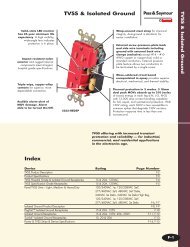
BURNDY ® ProductsMechanicalTYPE BIPCA-36UL Listed 90° C, *600 VoltThe TYPE BIPC, Burndy Insulation PiercingConnector is ideally suited for splicing andtapping aluminum and copper conductor wiresizes: #10 AWG to 500 kcmil. The BIPC'sunique insulation piercing design allows foruse on hot-line applications, eliminating theneed for taping.Features and Benefits• Insulation piercing capability. Eliminates the need for conductorinsulation stripping.• UL486B listed, AL9CU rated. For copper and aluminum conductorcombinations up to 90° *600 Voltapplications.• Insulation piercing design. For use on hot-line applications.Eliminates the need for taping.• Easy snap-out tabs. Eases installation, protects connectionfrom dirt and debris.• Simple bolt-on connection. Eases installation.Fig. 1 Fig. 2MAX.CATALOG CONDUCTOR RANGE BOLT SOCKET FIG. DIMENSIONS RECOMMENDED VOLTAGENUMBER RUN TAP SIZE SIZE NO. H L W TORQUE (N,m) RATINGBIPC1/0-21/0 - 8 AWG 2 - 8 AWG 2.00 1.53 2.56 180 in. lbs.[50 - 6 mm 2 ] [35 - 6 mm 2 5/16-18 1/2 1][51] [39] [65] [20.3 N.m]600VBIPC4/0-64/0 - 1/0 AWG 1/0 - 6 AWG 2.50 2.12 2.00 250 in. lbs.[95 - 50 mm 2 ] [50 - 16 mm 2 5/16-18 1/2 2][64] [54] [51] [28.3 N.m]300VBIPC4/0-1/04/0 - 1/0 AWG 4/0 - 1/0 AWG 2.50 2.12 2.06 250 in. lbs.[95 - 50 mm 2 ] [95 - 50 mm 2 5/16-18 1/2 2][64] [2.12] [52] [28.3 N.m]300VBIPC350-4/0350 - 4/0 AWG 4/0 - 10 AWG 3.00 1.59 2.50 375 in. lbs.[185 - 95 mm 2 ] [95 - 6 mm 2 3/8-16 9/16 1][76] [40] [64] [42.4 N.m]300VBIPC350-350350 - 4/0 AWG 350 - 4/0 AWG 3.00 2.62 2.75 300 in. lbs.[185 - 95 mm 2 ] [185 - 95 mm 2 3/8-16 9/16 2][76] [67] [70] [33.9 N.m]300VBIPC500-4/0500 - 350 kcmil 4/0 - 4 AWG 3.25 1.59 2.62 400 in. lbs.[240 - 185 mm 2 ] [95 - 25 mm 2 3/8-16 9/16 1][83] [40] [67] [45.2 N.m]600V
BURNDY ® ProductsMechanicalSPEC-BLOKPOWERDISTRIBUTIONCONNECTORSUnique, modular, made-to-order, powerdistributionassemblies accommodate anynumber of supply and load conductors in anynumber of poles. Capacity matches the conductorsaccommodated and SPEC-BLOKassures uniform loading.A-37Adjacent poles are separated by easy-tohandle,wrap-around insulating covers whicheliminate taping and reduce heat build-up byallowing air to flow freely around connectors.SPEC-BLOK is UL Listed for copper oraluminum conductors for 600 volts. (AL9CU)Assemblies are mounted on platforms suitablefor easy installation in wireway orjunction box.Features and Benefits• Accommodate unlimited conductors. Fits wide range of applications.Eliminates need for non-UL-listedimprovisation.• Connector elements tin-plated. Provides high reliability, low-resistanceconnections.• User friendly, space-saving design. Easy to install. Saves labor.• 94-VO rated insulation folds into placeinsulating the components. Saves time and material. Allowseasy installation.• Connector caps removable for easycable lay-in. Saves labor. Makes installation easier.Allows installation or straight-throughconductors. Eases retrofit.• Belleville washers built-in on pressurescrew assemblies, except in assembliesinstalled with a 5/32" Allen wrench. Provides high-integrity connections.• Conductors can be cut or fed straightthrough. Straight through installation ideal forriser applications.Contact Burndy or Technical Services, 1-800-451-4956or Burndy Customer Service, 1-800-346-4175
BURNDY ® ProductsMechanicalA-38SPEC-BLOKFeatures and Benefits• The SPEC-BLOK system includes12 connector elements A wide variety of conductor sizes canbe accommodated• Each element can be bolted togetherin parallel Provides an efficient flow of current fromone element to another• AL9CU rated for Copper or Aluminumconductors Dual-rated system, with UL486B’shighest temperature rating• 2 Wire (series), 4 (parallel), and Multi-Tapversions available Nearly any conductor combination canbe terminated• Tin-plated Aluminum Alloy Construction High-strength, corrosion-resistantconnector elements• All SPEC-BLOKs are custom made fornearly any Power Distribution systemrequirement Time savings — pre-assembled in ourfactory for immediate installation!EW D TSPEC-BLOK CONNECTORSC S B R A Q U PCATALOG DESIGNATION(MAXIMUMCONDUCTOR)4ConductorA2ConductorQNUMBER OFCONDUCTORSACCOMMODATED4Conductor2ConductorAL or CUWIRE RANGE UNDEREACH CAPFirstConductorsMUST BeSecondConductor(ifrequired)May Be1/0-2/0#12-2/ 0(2/0)B R 3/0-250#6-250(250)C S 1 to 4 (0, 11 or 2250-350#6-350or 2(350)per capper cap)D T 400-500#6-500(500)E W 600-7503/0-750(750)Height OnMaxConductorsDIMENSIONSWidthLength Without Insulator4Conductor2ConductorALLENWRENCHSIZE2-9/161-1/2 2-1./8 7 / 8 5/32"3-1/81-11/164-1/4 1-3/ 83-5/161-13/164-5/8 1-1/ 24-1/162 5-5/8 1-3/ 44-7/82-1/4 7-1/4 2-5/ 81/4"3/8"Catalog Designation(Maximum Conductor)P (1/0)U (1/0 & 500)Number of ConductorsAccommodated1 to 8 (0, 1 or 2 undereach screw)LargeGrooveSmallGrooves**Height OnMaximumConductorsWidth__ 6-1/0 3 1/2 22 to 9 (0, 1 or 2 undereach screw plus onelarge conductor) 3/0-500 6-1/0 4 1/8 2LengthWithoutInsulatorAllenWrenchSize1 3/4 5/32"** This range may be expanded to include #8 provided twoconductors are being installed in that particular element.
BURNDY ® ProductsMechanicalSPEC-BLOKMOUNTING PLATFORMSSPEC-BLOK Mounting Platforms are rigidsteel construction with a black finish. Theycan be supplied for junction box mounting orwireway construction allowing trough conductorsto pass underneath the assemblies.(CPB-)(CPT-)A-39CATALOG L L WNUMBER (Nominal) (Overall) (Overall)CPB6 6 7-3/4 2-1/2CPB8 8 9-3/4 2-1/2CPB10 10 11-3/4 2-1/2CPB12 12 13-3/4 3-1/2CPB16-5/8 16-5/8 18-3/8 3-1/2CPB21-1/4 21-1/4 23 3-1/2CATALOGNUMBER L W HCPT6 5-7/8 2-1/2 2-1/4CPT8 7-7/8 3-1/2 3CPT10 9-7/8 3-1/2 3-1/2CPT12 11-7/8 3-1/2 4CPT16 15-7/8 3-1/2 4SPEC-BLOK catalog numbers describe exactly how the distribution block is assembled:5DR-NDST-GQP-12(assembly pictured)5 Total number of poles in thecompleted assemblyDR One 'D' unit and one 'R' unit, boltedin parallel, forming each phase pole(3 phase poles)N Denotes the beginning of the neutralpole (where required)DST One 'D' unit, one 'S' unit, and on 'T'unit, bolted in parallel, forming theneutral poleGQPDenotes the beginning of the groundpole description (where required)One 'Q' unit and on 'P' unit, bolted inparallel, forming the ground pole.12 Size (inches) of the wireway or troughthat is needed to enclose the assembly.If a junction box enclosure is used,no number is used to denote the sizeof the enclosure.SPEC-BLOK IS A SYSTEM THAT CAN SOLVE MOST POWER DISTRIBUTION APPLICATIONS!
BURNDY ® ProductsMechanicalA-40QUESTIONNAIREFOR SPEC-BLOKOR ELECTRO-RAILAPPLICATIONSWhat is the total capacity of the system?_____________ampsHow many poles in the system(3-wire, 4-wire, single phase, etc.)?_____________polesAre neutral conductors (when required) different sizes (AWG/KCMil)than the phase conductors?Are any conductors continuous? ■ Yes ■ NoIf yes, which ones?_______________________________________________________________________________________What kind of enclosure is connection assembly being mounted intoand what are inside space dimensions?_________the same size__________different sizeTrough size _________________________________________Is a ground connection required? ■ Yes ■ NoWhat are the quantities, sizes (AWG/kcmil) and material (Al/Cu)of the incoming line conductors and outgoing load conductors?CONDUCTORTYPEQUANTITY SIZE (Cu/Al)Box, panel, cabinet, other size___________________________When is a quotation required? Date:______________________When is the material required? Date:_____________________Is there a preference for a particularBurndy distributor? ■ Yes ■ NoPERPHASEPERNEUTRALLINELOADLINELOADIf yes, give name, location & telephone Number:Name:______________________________________________Address:______________________________________________________________________________________________Phone #:____________________________________________PERGROUNDLINELOAD
BURNDY ® ProductsMechanicalVERSI-POLEPOWER DISTRIBUTIONBLOCKSA-41VERSI-POLE Power Distribution Blocksare designed to provide modular solutions topower distribution applications. Each connectorelement is made from a high conductivityaluminum alloy which is insulated with a highstrength polymer housing. One, two, andthree pole versions available. "Add" a pole(snap-together) blocks are also available forwire sizes up to 500 kcmil. For use with Cu orAl. 600 V, AL9CU rated.VERSI-POLE SNAP-TOGETHER BLOCKSFeatures and Benefits• "Add" a pole feature available. Provides capability to create as manypoles as required.• Up to 30 tap conductors accommodated. Ideal for current distribution to multiplelocations.• Single or dual run connections. Allows user to minimize the numberof connectors needed to do the job.• Suitable for use with aluminum orcopper conductors. Provides maximum versatility.• 600 V, AL9CU rated.* Meets or exceeds industry standardrequirements.• Dead-front covers available Provides user protection – one coverper pole.* BDB-430-500-1 not UL recognized or CSA certifiedRUN TAP AMPERECATALOG CONNECTOR WIRE RANGE WIRE RANGE RATING PER NUMBER OFNUMBER RUN TAP AL9CU AL9CU POLE POLESBDA-112-350 350 kcmil - 6 4 - 14 350 ADDERBDA-16-350 350 kcmil - 6 2/0 - 14 350 ADDERBDA-16-500 500 kcmil - 4 2/0 - 4 430 ADDERBDA-26-350 350 kcmil - 6 2/0 - 14 700 ADDERBDA-212-500 500 kcmil - 4 4 - 14 860 ADDERBDA-26-500 500 kcmil - 4 2/0 - 14 860 ADDERBDA-24-500 500 kcmil - 4 4/0 - 6 860 ADDERBDA-11-500 500 kcmil - 4 500 kcmil - 4 430 ADDERBDA-22-350 350 kcmil - 6 350 kcmil - 6 700 ADDERBDA-22-500 500 kcmil - 4 500 kcmil - 4 860 ADDERNOTES:1. Order Optional BDB COVER1 per pole if desired.2. Snap-together blocks can also be assembled to 1, 2, 3pole blocks to create multi-pole distribution blocks.
BURNDY ® ProductsMechanicalVERSI-POLEA-42VERSI-POLE 1, 2, 3 POLEDISTRIBUTION BLOCKSRUN TAP AMPERE OPTIONALCATALOG CONNECTOR WIRE RANGE WIRE RANGE RATING PER NUMBER OF COVER ORDERNUMBER RUN TAP AL9CU AL9CU POLE POLES 1 PER POLEBDB-16-2/0-1 1BDB-16-2/0-2 2/0 - 12 4 - 14 195 2 BDBCOVER2BDB-16-2/0-3 3BDB-26-2/0-1 1BDB-26-2/0-2 2/0 - 14 2 - 14 390 2 BDBCOVER2BDB-26-2/0-3 3BDB-112-350-1 1BDB-112-350-2 350 kcmil - 6 4 - 14 350 2 BDBCOVER1BDB-112-350-3 3BDB-16-350-1 1BDB-16-350-2 350 kcmil - 6 2/0 - 14 350 2 BDBCOVER1BDB-16-350-3 3BDB-14-500-1 1BDB-14-500-2 500 kcmil - 4 2/0 - 14 430 2 BDBCOVER2BDB-14-500-3 3BDB-16-500-1 1BDB-16-500-2 500 kcmil - 4 2/0 - 14 430 2 BDBCOVER1BDB-16-500-3 3BDB-162-500-1 1BDB-162-500-2 500 kcmil - 4 2 - 14 430 2 BDBCOVER2BDB-162-500-3 3BDB-26-350-1 1BDB-26-350-2 350 kcmil - 6 2/0 - 14 700 2 BDBCOVER1BDB-26-350-3 3BDB-212-500-1 1BDB-212-500-2 500 kcmil - 4 4 - 14 860 2 BDBCOVER1BDB-212-500-3 3BDB-26-500-1 1BDB-26-500-2 500 kcmil - 4 2/0 - 14 860 2 BDBCOVER1BDB-26-500-3 3BDB-24-500-1 1BDB-24-500-2 500 kcmil - 4 4/0 - 6 860 2 BDBCOVER1BDB-24-500-3 3
BURNDY ® ProductsMechanicalVERSI-POLEVERSI-POLE 1, 2, 3SPLICE/REDUCER BLOCKSA-43RUN TAP AMPERE OPTIONALCATALOG CONNECTOR WIRE RANGE WIRE RANGE RATING PER NUMBER OF COVER ORDERNUMBER RUN TAP AL9CU AL9CU POLE POLES 1 PER POLEBDB-11-2/0-1 1BDB-11-2/0-2 2/0 - 14 2/0 - 14 195 2 BDBCOVER2BDB-11-2/0-3 3BDB-11-350-1 1BDB-11-350-2 350 kcmil - 6 350 kcmil - 6 350 2 BDBCOVER2BDB-11-350-3 3BDB-11-500-1 1BDB-11-500-2 500 kcmil - 6 500 kcmil - 6 430 2 BDBCOVER1BDB-11-500-3 3BDB-22-2/0-1 1BDB-22-2/0-2 2/0 - 14 2/0 - 14 390 2 BDBCOVER2BDB-22-2/0-3 3BDB-22-350-1 1BDB-22-350-2 350 kcmil - 6 350 kcmil - 6 700 2 BDBCOVER1BDB-22-350-3 3BDB-22-500-1 1BDB-22-500-2 500 kcmil - 4 500 kcmil - 4 860 2 BDBCOVER1BDB-22-500-3 3SNAP TOGETHERSPLICER/REDUCERBLOCKSRUN TAP AMPERE OPTIONALCATALOG CONNECTOR WIRE RANGE WIRE RANGE RATING PER NUMBER OF COVER ORDERNUMBER RUN TAP AL9CU AL9CU POLE POLES 1 PER POLEBDC-14-2/0-1 2/0 - 14 4 - 14 195 1 BDBCOVER3BDA-14-2/0-1 2/0 - 14 4 - 14 195 ADDER BDBCOVER3BDC-11-2/0-1 2/0 - 14 2/0 - 14 195 1 BDBCOVER3BDA-11-2/0-1 2/0 - 14 2/0 - 14 195 ADDER BDBCOVER3
BURNDY ® ProductsMechanicalVERSI-POLE(Continued)A-44VERSI-POLE 1, 2, 3SPLICE/REDUCER BLOCKSThese tables and illustrations refer to VERSI-POLE Power Distribution Blocks listed onpages A-48 through A-50.THE FIGURE TO THE LOWER RIGHT IS APPLICABLE TO THE FOLLOWING:Catalog Number Number of Poles Catalog Number Number of PolesBDA-11-500 1 (adder) BDB-16-500-3 3BDA-112-350 1 (adder) BDB-212-500-1 1BDA-16-350 1 (adder) BDB-212-500-2 2BDA-16-500 1 (adder) BDB-212-500-3 3BDA-212-500 1 (adder) BDB-22-350-1 1BDA-22-350 1 (adder) BDB-22-350-2 2BDA-22-500 1 (adder) BDB-22-350-3 3BDA-24-500 1 (adder) BDB-22-500-1 1BDA-26-350 1 (adder) BDB-22-500-2 2BDA-26-500 1 (adder) BDB-22-500-3 3BDB-11-500-1 1 BDB-24-500-1 1BDB-11-500-2 2 BDB-24-500-2 2BDB-11-500-3 3 BDB-24-500-3 3BDB-112-350-1 1 BDB-26-350-1 1BDB-112-350-2 2 BDB-26-350-2 2BDB-112-350-3 3 BDB-26-350-3 3BDB-16-350-1 1 BDB-26-500-1 1BDB-16-350-2 2 BDB-26-500-2 2BDB-16-350-3 3 BDB-26-500-3 3BDB-16-500-1 1 BDB-430-500-1 1BDB-16-500-2 2NO. OF DIMENSIONS APOLESINCHESAdder 2.501 2.812 5.313 7.81N (2.50 X N) + .31Example for 10 poles:A = (2.50 X 10) + .31 = 25
BURNDY ® ProductsMechanicalVERSI-POLE(Continued)VERSI-POLE 1, 2, 3SPLICE/REDUCER BLOCKSA-45These tables and illustrations refer to VERSI-POLE Power Distribution Blocks listed onpages A-48 through A-50.THE FIGURE TO THE RIGHT ISAPPLICABLE TO THE FOLLOWING:Catalog NumberBDB-11-2/0-1 1BDB-11-2/0-2 2BDB-11-2/0-3 3BDB-11-350-1 1BDB-11-350-2 2BDB-11-350-3 3BDB-14-500-1 1BDB-14-500-2 2BDB-14-500-3 3BDB-16-2/0-1 1BDB-16-2/0-2 2BDB-16-2/0-3 3BDB-162-500-1 1BDB-162-500-2 2BDB-162-500-3 3BDB-22-2/0-1 1BDB-22-2/0-2 2BDB-22-2/0-3 3BDB-26-2/0-1 1BDB-26-2/0-2 2BDB-26-2/0-3 3Number of PolesNO. OF DIMENSIONS APOLESINCHESAdder 1.641 1.942 3.573 5.20N (1.64 X N) + .30Example for 10 poles:A = (1.64 X 10) + .30 = 16.20APPLICABLE VERSI-POLE TM ITEMSCatalog Number Number of PolesBDA-14-2/0-11 (adder)BDC-14-2/0-1 1BDA-11-2/0-11 (adder)BDC-11-2/0-1 1NO. OF DIMENSIONS APOLESINCHESAdder .811 1.082 1.893 2.70N (.81 X N) + .27Example for 10 poles:A = (.81 X 10) + .27 = 8.37
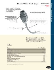
BURNDY ® ProductsMechanicalBURNDY UNITAPA-46CLEAR INSULATEDMULTIPLE TAP CONNECTORSTap connections and in-line splice/reductionsare made quickly and easily with theUNITAP line of connectors. UL486B Listed.Dual-rated AL9CU for any stranded copper orstranded aluminum applications. 600 Volt,90° C.Features and Benefits2 PORT 1 or 2 Sided Entry* Not UL Listed• Clear Plastisol covered AL6061-T6aluminum body. Saves time, lowers installation costs,eliminates taping.• Clear Plastisol. Allows visual confirmation thatconductor is properly inserted.Catalog # of Wire Range Fig.Number Ports (AWG/kcmil) L W H Hex Key No.BIT4 2 #14 - #4 1.16 1.16 1.25 1/8 1BITO4 2 #14 - #4 1.16 1.50 1.25 1/8 2BIT2/0 2 #14 - 2/0 1.52 1.40 1.38 3/16 1BITO2/0 2 #14 - 2/0 1.52 1.56 1.38 3/16 2BIT250 2 #10 - 250 2.03 2.07 2.13 5/16 1BITO250 2 #10 - 250 2.03 2.64 2.13 5/16 2BIT350 2 #10 - 350 2.22 2.32 2.50 5/16 1BITO350 2 #10 - 350 2.22 3.00 2.50 5/16 2BIT600 2 #4 - 600 2.72 2.38 2.75 3/8 1BITO600 2 #4 - 600 2.72 3.00 2.75 3/8 2BIT750* 2 #2 - 750 2.87 2.70 3.00 3/8 1BITO750* 2 #2 - 750 2.87 3.38 3.00 3/8 2• Oxide inhibitor pre-installed. Inhibits moisture and contaminantsfrom entering the contact area.• Range-taking. Reduces number of connectors carriedin inventory.Fig. 1Fig. 2IN-LINE SPLICER/REDUCERCatalog Wire RangeNumber (AWG/kcmil) L W H Hex KeyBISR2 #14 - 2 2.38 0.75 1.22 5/32BISR1/0 #14 - 1/0 2.91 0.91 1.38 3/16BISR250 #10 - 250 4.01 1.19 2.10 5/16BISR350 #10 - 350 4.63 1.34 2.35 5/16BISR500 #6 - 500 5.00 1.62 2.62 3/8
BURNDY ® ProductsMechanicalBURNDY UNITAPA-47MULTI-PORTSingle-Sided EntryCatalog # of Wire Range HexNumber Ports (AWG/kcmil) L W H KeyBIBS4-3 3 #14 - 4 1.59 1.25 1.25 1/8BIBS4-4 4 #14 - 4 2.03 1.25 1.25 1/8BIBS4-5 5 #14 - 4 2.47 1.25 1.25 1/8BIBS4-6 6 #14 - 4 2.91 1.25 1.25 1/8BIBS4-8 8 #14 - 4 3.78 1.25 1.25 1/8BIBS2/0-3 3 #14 - 2/0 2.19 1.31 1.38 3/16BIBS2/0-4 4 #14 - 2/0 2.86 1.31 1.38 3/16BIBS2/0-5 5 #14 - 2/0 3.53 1.31 1.38 3/16BIBS2/0-6 6 #14 - 2/0 4.20 1.31 1.38 3/16BIBS2/0-8 8 #14 - 2/0 5.55 1.31 1.38 3/16BIBS2/0-10 10 #14 - 2/0 6.89 1.31 1.38 3/16BIBS2/0-12 12 #14 - 2/0 8.24 1.31 1.38 3/16BIBS2/0-14 14 #14 - 2/0 9.58 1.31 1.38 3/16BIBS250-3 3 #10 - 250 2.97 2.07 2.13 5/16BIBS250-4 4 #10 - 250 3.91 2.07 2.13 5/16BIBS250-5 5 #10 - 250 4.84 2.07 2.13 5/16BIBS250-6 6 #10 - 250 5.78 2..07 2.13 5/16BIBS250-8 8 #10 - 250 7.66 2.07 2.13 5/16BIBS250-10 10 #10 - 250 9.53 2.07 2.13 5/16BIBS250-12 12 #10 - 250 11.41 2.07 2.13 5/16BIBS250-14 14 #10 - 250 13.29 2.07 2.13 5/16BIBS350-3 3 #10 - 350 3.13 2.32 2.50 5/16Catalog # of Wire Range HexNumber Ports (AWG/kcmil) L W H KeyBIBS350-4 4 #10 - 350 4.04 2.32 2.50 5/16BIBS350-5 5 #10 - 350 4.95 2.32 2.50 5/16BIBS350-6 6 #10 - 350 5.86 2.32 2.50 5/16BIBS350-8 8 #10 - 350 7.68 2.32 2.50 5/16BIBS350-10 10 #10 - 350 9.50 2.32 2.50 5/16BIBS350-12 12 #10 - 350 11.32 2.32 2.50 5/16BIBS350-14 14 #10 - 350 13.14 2.32 2.50 5/16BIBS600-3 3 #4 - 600 4.00 2.38 2.75 3/8BIBS600-4 4 #4 - 600 5.28 2.38 2.75 3/8BIBS600-5 5 #4 - 600 6.56 2.38 2.75 3/8BIBS600-6 6 #4 - 600 7.84 2.38 2.75 3/8BIBS600-8 8 #4 - 600 10.41 2.38 2.75 3/8BIBS600-10 10 #4 - 600 12.97 2.38 2.75 3/8BIBS600-12 12 #4 - 600 15.53 2.38 2.75 3/8BIBS600-14 14 #4 - 600 18.09 2.38 2.75 3/8BIBS750-3* 3 #2 - 750 4.25 2.70 3.00 3/8BIBS750-4* 4 #2 - 750 5.63 2.70 3.00 3/8BIBS750-6* 6 #2 - 750 8.37 2.70 3.00 3/8BIBS750-8* 8 #2 - 750 11.13 2.70 3.00 3/8BIBS750-10* 10 #2 - 750 13.87 2.70 3.00 3/8BIBS750-12* 12 #2 - 750 16.63 2.70 3.00 3/8BIBS750-14* 14 #2 - 750 19.37 2.70 3.00 3/8* Not UL Listed
BURNDY ® ProductsMechanicalBURNDY UNITAPA-48MULTI-PORTDouble-Sided EntryCatalog # of Wire Range HexNumber Ports (AWG/kcmil) L W H KeyBIBD4-2 2 #14 - #4 1.16 1.50 1.25 1/8BIBD4-3 3 #14 - #4 1.59 1.50 1.25 1/8BIBD4-4 4 #14 - #4 2.03 1.50 1.25 1/8BIBD4-5 5 #14 - #4 2.47 1.50 1.25 1/8BIBD4-6 6 #14 - #4 2.91 1.50 1.25 1/8BIBD4-8 8 #14 - #4 3.78 1.50 1.25 1/8BIBD2/0-2 2 #14 - 2/0 1.52 1.56 1.25 3/16BIBD2/0-3 3 #14 - 2/0 2.19 1.56 1.25 3/16BIBD2/0-4 4 #14 - 2/0 2.86 1.56 1.25 3/16BIBD2/0-5 5 #14 - 2/0 3.53 1.56 1.25 3/16BIBD2/0-6 6 #14 - 2/0 4.20 1.56 1.25 3/16BIBD2/0-8 8 #14 - 2/0 5.55 1.56 1.25 3/16BIBD2/0-10 10 #14 - 2/0 6.89 1.56 1.25 3/16BIBD2/0-12 12 #14 - 2/0 8.24 1.56 1.25 3/16BIBD2/0-14 14 #14 - 2/0 9.58 1.56 1.25 3/16BIBD250-2 2 #10 - 250 2.03 2.64 2.13 5/16BIBD250-3 3 #10 - 250 2.97 2.64 2.13 5/16BIBD250-4 4 #10 - 250 3.91 2.64 2.13 5/16BIBD250-5 5 #10 - 250 4.84 2.64 2.13 5/16BIBD250-6 6 #10 - 250 5.78 2.64 2.13 5/16BIBD250-8 8 #10 - 250 7.66 2.64 2.13 5/16BIBD250-10 10 #10 - 250 9.53 2.64 2.13 5/16BIBD250-12 12 #10 - 250 11.41 2.64 2.13 5/16BIBD250-14 14 #10 - 250 13.29 2.64 2.13 5/16BIBD350-2 2 #10 - 350 2.22 3.00 2.50 5/16Catalog # of Wire Range HexNumber Ports (AWG/kcmil) L W H KeyBIBD350-3 3 #10 - 350 3.13 3.00 2.50 5/16BIBD350-4 4 #10 - 350 4.04 3.00 2.50 5/16BIBD350-5 5 #10 - 350 4.95 3.00 2.50 5/16BIBD350-6 6 #10 - 350 5.86 3.00 2.50 5/16BIBD350-8 8 #10 - 350 7.68 3.00 2.50 5/16BIBD350-10 10 #10 - 350 9.50 3.00 2.50 5/16BIBD350-12 12 #10 - 350 11.32 3.00 2.50 5/16BIBD350-14 14 #10 - 350 13.14 3.00 2.50 5/16BIBD600-2 2 #4 - 600 2.56 3.00 2.75 3/8BIBD600-3 3 #4 - 600 3.77 3.00 2.75 3/8BIBD600-4 4 #4 - 600 4.97 3.00 2.75 3/8BIBD600-5 5 #4 - 600 6.17 3.00 2.75 3/8BIBD600-6 6 #4 - 600 7.37 3.00 2.75 3/8BIBD600-8 8 #4 - 600 9.78 3.00 2.75 3/8BIBD600-10 10 #4 - 600 12.97 3.00 2.75 3/8BIBD600-12 12 #4 - 600 15.53 3.00 2.75 3/8BIBD600-14 14 #4 - 600 18.09 3.00 2.75 3/8BIBD750-2* 2 #2 - 750 2.87 3.38 3.00 3/8BIBD750-3* 3 #2 - 750 4.25 3.38 3.00 3/8BIBD750-4* 4 #2 - 750 5.63 3.38 3.00 3/8BIBD750-6* 6 #2 - 750 8.37 3.38 3.00 3/8BIBD750-8* 8 #2 - 750 11.13 3.38 3.00 3/8BIBD750-10* 10 #2 - 750 13.87 3.38 3.00 3/8BIBD750-12* 12 #2 - 750 16.63 3.38 3.00 3/8BIBD750-14* 14 #2 - 750 19.37 3.38 3.00 3/8NOTE: Only 1 conductor per port allowed.* Not UL Listed
BURNDY ® ProductsMechanicalBURNDY UNITAPCLEAR INSULATEDMULTIPLE TAP CONNECTORSA-49MOUNTING VERSIONTYPE BIBS-MT, BIBD-MTThe BIBS-MT and BIBD-MT series UNITAPoffer the same multi-port capabilities as thestandard UNITAP connectors except these-MT types are provided with two isolatedmounting holes at both ends of the connectorfor direct mounting to a trough, gutter orwireway. They will accommodate up tostandard 1/4 hardware.Fig. 1 Fig. 2MULTI-PORTSingle-Sided EntryCatalog # of Wire Range HexNumber Fig # Ports (AWG/Kcmil) L W H KeyBIBS2/04MT 1 4 #14-2/0 3.95 1.31 1.38 3/16BIBS2/06MT 1 6 #14-2/0 5.29 1.31 1.38 3/16BIBS2/08MT 1 8 #14-2/0 6.64 1.31 1.38 3/16BIBS2/010MT 1 10 #14-2/0 7.98 1.31 1.38 3/16BIBS2/012MT 1 12 #14-2/0 9.33 1.31 1.38 3/16BIBS2504MT 1 4 #10-250 5.53 2.07 2.13 5/16BIBS2506MT 1 6 #10-250 7.40 2.07 2.13 5/16BIBS2508MT 1 8 #10-250 9.28 2.07 2.13 5/16BIBS25010MT 1 10 #10-250 11.16 2.07 2.13 5/16BIBS25012MT 1 12 #10-250 13.03 2.07 2.13 5/16BIBS3504MT 1 4 #10-350 5.61 2.32 2.50 5/16BIBS3506MT 1 6 #10-350 7.43 2.32 2.50 5/16BIBS3508MT 1 8 #10-350 9.25 2.32 2.50 5/16BIBS35010MT 1 10 #10-350 11.07 2.32 2.50 5/16BIBS35012MT 1 12 #10-350 12.89 2.32 2.50 5/16BIBS6004MT 1 4 #4-600 7.59 2.38 2.75 3/8BIBS6006MT 1 6 #4-600 10.16 2.38 2.75 3/8BIBS6008MT 1 8 #4-600 12.72 2.38 2.75 3/8BIBS60010MT 1 10 #4-600 15.28 2.38 2.75 3/8BIBS60012MT 1 12 #4-600 17.84 2.38 2.75 3/8MULTI-PORTDouble-Sided EntryCatalog # of Wire Range HexNumber Fig # Ports (AWG/Kcmil) L W H KeyBIBD2/04MT 2 4 #14-2/0 3.95 1.56 1.38 3/16BIBD2/06MT 2 6 #14-2/0 5.29 1.56 1.38 3/16BIBD2/08MT 2 8 #14-2/0 6.64 1.56 1.38 3/16BIBD2/010MT 2 10 #14-2/0 7.98 1.56 1.38 3/16BIBD2/012MT 2 12 #14-2/0 9.33 1.56 1.38 3/16BIBD2504MT 2 4 #10-250 5.53 2.64 2.13 5/16BIBD2506MT 2 6 #10-250 7.40 2.64 2.13 5/16BIBD2508MT 2 8 #10-250 9.28 2.64 2.13 5/16BIBD25010MT 2 10 #10-250 11.16 2.64 2.13 5/16BIBD25012MT 2 12 #10-250 13.03 2.64 2.13 5/16BIBD3504MT 2 4 #10-350 5.61 3.00 2.50 5/16BIBD3506MT 2 6 #10-350 7.43 3.00 2.50 5/16BIBD3508MT 2 8 #10-350 9.25 3.00 2.50 5/16BIBD35010MT 2 10 #10-350 11.07 3.00 2.50 5/16BIBD35012MT 2 12 #10-350 12.89 3.00 2.50 5/16BIBD6004MT 2 4 #4-600 7.59 3.00 2.75 3/8BIBD6006MT 2 6 #4-600 10.16 3.00 2.75 3/8BIBD6008MT 2 8 #4-600 12.72 3.00 2.75 3/8BIBD60010MT 2 10 #4-600 15.28 3.00 2.75 3/8BIBD60012MT 2 12 #4-600 17.84 3.00 2.75 3/8
BURNDY ® ProductsMechanicalBURNDY UNITAPTHE MOLEA-50For Direct Burial600V, 90°CDesigned specifically for direct burial applications,the MOLE inline splice/reducer ismade with a specialized plastisol materialthat forms a rugged weathertight connection.Features and Benefits• UL486D Listed for direct burial.• AL9CU Dual-rated for copper andaluminum applications. 600V 90°C.• Plastisol covered AL6061-T6 aluminumbody saves time by eliminating the needfor heat shrink.• Oxide inhibitor pre-installed preventingmoisture and contaminants from enteringcontact area.• Range-taking capability reduces thenumber of connectors carried in inventory.Number Wire Hex Key WireCatalog of Range Dimensions (Inches) (Torque) StripNumber Ports (AWG/kcmil) L W H (In.-lbs.) LengthBISR4-DB 2 #6 - 4 AWG 4.30 0.80 1.281/8(50)7/8BISR1-DB 2 #2 - 1 AWG 6.30 0.93 1.595/32(130)1-3/32BISR3/0-DB 2 1/0 - 3/0 AWG 6.25 0.99 1.843/16(220)1-3/32BISR250-DB 2 4/0 - 250 kcmil 6.70 1.18 2.035/16(360)1-5/16BISR-DB = BURNDY Inline Splice/Reducer Direct Burial
BURNDY ® ProductsMechanicalUV RATEDBLACK UNITAP600V, 90°CA-51Features and Benefits• UV Rated Plastisol covered AL6061-T6aluminum body saves time by eliminatingthe need for taping.• Oxide inhibitor pre-installed inhibitsmoisture and contaminants fromentering the contact area.• Range-taking capability reduces thenumber of connectors carried in inventory.• UL486B Listed, AL9CU, 600V 90°CNumber Wire Hex Key WireCatalog of Range Dimensions (Inches) (Torque) StripNumber Ports (AWG/kcmil) L W H (In.-lbs.) Length1PL42 2 #14 - 4 1.16 1.16 1.25 1/8 (45) 5/81PLO42 2 #14 - 4 1.16 1.50 1.25 1/8 (45) 5/81PL2/02 2 #14 - 2/0 1.52 1.40 1.38 3/16 (120) 11/161PLO2/02 2 #14 - 2/0 1.52 1.56 1.38 3/16 (120) 11/161PL2502 2 #10 - 250 2.03 2.07 2.13 5/16 (275) 11PLO2502 2 #10 - 250 2.03 2.64 2.13 5/16 (275) 11PL3502 2 #10 - 350 2.22 2.32 2.50 5/16 (275) 1-1/81PL6002 2 #4 - 600 2.72 2.38 2.75 3/8 (375) 1-1/81PLO6002 2 #4 - 600 2.72 3.00 2.75 3/8 (375) 1-1/81PBS2 2 #14 - 2 2.38 0.75 1.22 5/32 (45) 3/41PBS1/0 2 #14 - 1/0 2.91 0.91 1.38 3/16 (120) 11PBS250 2 #10 - 250 4.01 1.19 2.10 5/16 (120) 1-3/161PBS350 2 #10 - 350 4.63 1.34 2.35 5/16 (275) 1-3/81PBS500 2 #6 - 500 5.00 1.62 2.62 3/8 (375) 1-1/21PL43 3 #14 - 4 1.59 1.25 1.25 1/8 (45) 5/81PL44 4 #14 - 4 2.03 1.25 1.25 1/8 (45) 5/81PL2/03 3 #14 - 2/0 2.19 1.31 1.38 3/16 (120) 11/161PL2503 3 #10 - 250 2.97 2.07 2.13 5/16 (275) 11PLD43 3 #14 - 4 1.59 1.50 1.25 1/8 (45) 5/81PLD44 4 #14 - 4 2.03 1.50 1.25 1/8 (45) 5/81PLD2/02 2 #14 - 2/0 1.52 1.56 1.25 3/16 (120) 11/161PLD2/03 3 #14 - 2/0 2.19 1.56 1.25 3/16 (120) 11/161PLD2/04 4 #14 - 2/0 2.86 1.56 1.25 3/16 (120) 11/161PLD2/06 6 #14 - 2/0 4.20 1.56 1.25 3/16 (120) 11/161PLD2502 2 #10 - 250 2.03 2.64 2.13 5/16 (275) 11PLD2503 3 #10 - 250 2.97 2.64 2.13 5/16 (275) 11PLD2504 4 #10 - 250 3.91 2.64 2.13 5/16 (275) 11PLD2506 6 #10 - 250 5.78 2.64 2.13 5/16 (275) 11PLD3502 2 #10 - 350 2.22 3.00 2.50 5/16 (375) 1-1/81PLD3503 3 #10 - 350 3.13 3.00 2.50 5/16 (375) 1-1/81PLD3504 4 #10 - 350 4.04 3.00 2.50 5/16 (375) 1-1/81PLD3506 6 #10 - 350 5.86 3.00 2.50 5/16 (375) 1-1/81PLD3508 8 #10 - 350 7.68 3.00 2.50 5/16 (375) 1-1/81PLD6002 2 #4 - 600 2.56 3.00 2.75 3/8 (375) 1-1/81PLD6003 3 #4 - 600 3.77 3.00 2.75 3/8 (375) 1-1/81PLD6004 4 #4 - 600 4.97 3.00 2.75 3/8 (375) 1-1/81PLD6005 5 #4 - 600 6.17 3.00 2.75 3/8 (375) 1-1/81PLD6006 6 #4 - 600 7.37 3.00 2.75 3/8 (375) 1-1/81PLD6008 8 #4 - 600 9.78 3.00 2.75 3/8 (375) 1-1/81PL = 2 Port Single Sided Entry1PLO = 2 Port Offset Entry1PBS = In-line Splice/Reducer1PL = Multi-Port Single Sided Entry1PLD = Multi-Port Double Sided Entry
BURNDY ® ProductsCompressionSMALL HYDENTTABLE OF CONTENTSGeneral Information ........................B-2, B-3MIL. SPEC. Equivalent Tables ................B-4Types T & YAD ........................................B-5Types TP & BA ......................................B-6Types TN & YAES ..........................B-7, B-8Type YAE-G BOX ..................................B-9Types YAE-N BOX & YAE-N ................B-10Type YAES-K ..............................B-11, B-12Types YAV BOX & YAV................B-13, B-14Types YAV-L BOX & YAV-L ........B-15, B-16Types YAV-H BOX & YAV-H ..................B-17Type YBM ............................................B-18Types YAEV & YAEV-L................B-19, B-20Type YAEV-H ..............................B-21, B-22Types YAV-R & YAV-RS ........................B-23Type YAEV-RS ......................................B-24Type YAEV-RH ......................................B-25Types T-F & YAD-F................................B-26Types YAV-T-F BOX & YAV-T-F ............B-27Types YAV-H-F BOX, YAV-H-F& YAV-Z ............................................B-28Types TN-F & YAES-F ..........................B-29Types YAE-N-F BOX & YAE-N-F ..........B-30Types TP-F & BA-EF ............................B-31Types YAE-Z BOX & YAE-Z ..................B-32Types TP-Z & BA-EZ ............................B-33Types TP-LF & BA-EL ..........................B-34Type Q-F................................................B-35Type QP-F ............................................B-35Type QN-F ............................................B-36Type QM ................................................B-36Type QP-M ............................................B-37Type QN-M ............................................B-37Types PGP & PGN ................................B-38Types FQN-F & FQN-M ........................B-39Type FL..................................................B-40Uninsulated Splices ..............................B-41Types YSV, YSV-H & YSV-L ................B-41Type YSV-L............................................B-42Type YSM ..............................................B-43Type YSCM............................................B-44Types YSES-K ......................................B-45Types SP & BS......................................B-46Insulated Splices ..................................B-47Types SN, YSE-HN................................B-47Types SNM, YSE BOX, YSES,YSE-H BOX, YSE & YSE-H ..............B-48Types YSV & YRV-L ..............................B-49Types YQE & RK ..................................B-50B-1
BURNDY ® ProductsCompressionB-2PerformanceThe terminals and splices in this catalog areapproved, per MIL-T-7928 and/or UL 486,where indicated. Table 1 shows the performancerequirements for terminals used inmilitary and commercial equipment. The voltagedrops listed are maximum allowablevalues taken at currents well above rated currentfor the wires. Tensile values assure thatthe wires will not become separated from theterminals under reasonably expected stresses.UL tensile values are chosen to reflect theseverest expected duty. MIL Specification tensilevalues apply only to crimp terminationsand reflect minimum values that are obtainedin good crimp joints. Actual performance ofBurndy terminals exceeds the requirementsof Table 1. Typical values are shown in Figs.1-5. For High Temperature applicationBURNDY ® YAV series with nickel plating "-NK" suffix provide for continuous operation to650° F and 750° F intermittent service.Table 1WIRE SIZEPERFORMANCE REQUIREMENTS - TERMINALS FOR COPPER WIREPER MIL-T-7928 PER UL 486TESTCURRENT(Amps)MAX.VOLTAGEDROP(Mv).MIN.TENSILESTRENGTH(Lbs.)MIN.TENSILESTRENGTH(Lbs.)TESTCURRENTFOR MAX.50˚C RISE(Amps)26 3 8 7 — —24 4.5 8 10 — —22 9 7 15 8 —20 11 6 19 13 —18 16 5 38 20 —16 22 7 50 30 —14 32 6 70 50 1512 41 5 110 70 2010 55 5 150 80 308 73 5 225 90 506 101 5 300 100 654 135 5 400 140 852 181 5 550 180 1151 211 5 650 200 1300 245 5 700 250 15000 283 5 750 300 175000 320 5 825 350 2000000 380 5 875 450 230Fig 1. Tensile strength of YADHYLUG after axialrotation stresses.Fig 2. Tensile strength of BAVINYLUG after axialrotation stresses.TENSILE STRENGTH IN POUNDSTENSILE STRENGTH IN POUNDSCOMMERCIAL WIRE SIZECOMMERCIAL WIRE SIZE
BURNDY ® ProductsCompressionGENERALINFORMATION(Continued)Fig 3. Tensile strength of YAESINSULUG aftervibration.Fig 5. Voltage drops of YAES atcurrents per Table 1 aftervibration.B-3TENSILE STRENGTH IN POUNDSVOLTAGE DROP mVAN WIRE SIZEAN WIRE SIZEDEGREES CENTIGRADETERMINALSIZEFig 4. Temperature rise of BAVINYLUG at currentsper Table 1.COMMERCIAL WIRE SIZE
BURNDY ® ProductsCompressionTYPES T AND YADDEEP “V” GROOVESERRATIONSLONG BRAZEDSEAM BARRELHYLUGUNINSULATEDCOMPRESSION TERMINAL,RING TONGUEELECTRO-TINPLATEDWIRECRIMPB-5The Type T uninsulated terminals are constructedof pure electrolytic copper. Designedwith a long brazed seam barrel, standardneck, deep V groove inner serrations andelectro-tin plated. The terminals are ideal forcontrol wiring and other standard dutyapplications.The ring tongue provides a secure terminationunder the screw head that cannot beremoved without the complete removal of thescrew. Two or more terminals can easily bestacked on a common stud.WIRE RANGEFeatures and BenefitsRINGTONGUE• Constructed of pure electrolytic copper. Provides maximum conductivity, lowresistance and ductility for excellentcrimp forming properties.• Long brazed seam barrel and deepV groove inner serrations. Provides optimum conductivity reliabilityand holding power after crimping.• Electro-tin plated. Provides durable long-lastingcorrosion resistance.• Wire range is clearly marked on terminal. Provides easy identification.• Inspection hole. Provides an easy visual check ofwire insertion.• Long neck terminal. Permits easy bending and stacking ofseveral terminals on a common stud.DIMENSIONS BULK TAPE MOUNTED WIRECATALOG WIRE STUD L Y Z CATALOG INSTALLATION CATALOG NO. INSTALLATION STRIPNUMBER RANGE SIZE C MAX. MAX. MIN. NUMBER* TOOLING 2000/Reel TOOLING LENGTHT18-4 3, 4 .25 .65 .53 .24 YAD18-4 Non-Ratchet: YAD18-4MT18-6 4-6 .25 .65 .53 .24 YAD18-6 Y10D, YAD18-6MTFMT18-8 6-8 .31 .77 .61 .33 YAD18-8 Y10-22 YAD18-8MwithT18-10 22-18 8-10 .31 .77 .61 .33 YAD18-10 Ratchet: YAD18-10MDFM6D1T18-14 1/4 .45 .96 .73 .44 YAD18-14 MR8G98, YAD18-14MDieT18-516 5/16 .45 .96 .73 .44 YAD18-516 Y8MRB-1, YAD18-516M9/32T18-38 3/8 .53 1.05 .78 .49 YAD18-38 MR20 YAD18-38MT14-4 3, 4 .25 .67 .55 .26 YAD14-4 Non-Ratchet: YAD14-4MT14-6 4-6 .25 .67 .55 .26 YAD14-6 Y10D, YAD14-6MTFMT14-8 6-8 .31 .77 .61 .33 YAD14-8 Y10-22 YAD14-8MwithT14-10 20-14 8-10 .31 .77 .61 .33 YAD14-10 Ratchet: YAD14-10MDFM5D1T14-14 1/4 .45 .96 .73 .44 YD14-14 MR8G98, YAD14-14MDieT14-516 5/16 .45 .96 .73 .44 YAD14-516 Y8MRB-1, YAD14-516M9/32T14-38 3/8 .53 1.05 .78 .49 YAD14-38 MR20 YAD14-38MT10-6 4-6 .37 .83 .64 .29 YAD10-6 Non-Ratchet: •YAD10-6MT10-8 6-8 .37 .83 .64 .29 YAD10-8 Y10D, Y10-22 •YAD10-8M TFMT10-10 8-10 .37 .83 .64 .29 YAD10-10 Ratchet: •YAD10-10M with12-10*T10-141/4 .46 .97 .74 .39 YAD10-14 MR8G98, *YAD10-14M DFM4D1 11/32T10-516 5/16 .53 1.02 .76 .41 YAD10-516 Y8MRB-1, *YAD10-516M DieT10-38 3/8 .58 1.08 .79 .44 YAD10-38 MR20 *YAD10-38M* NOTE: UL Listed for 14-10 when installed with MR8G98and Y8MRB-1 tools only.• 1000 pcs/reel.
BURNDY ® ProductsCompressionTYPES TP AND BAWIRECRIMPEXPANDED SHROUDINSULATION CRIMPB-6VINYLUGTERMINAL -POLYVINYLCHLORIDEINSULATED, RING TONGUE600 VOLTS MAX. 105° C MAX.RINGTONGUEWIRE SIZERANGETINPLATEDDEEP “V”SERRATIONSSMOOTHENTRYCOLOR CODEDINSULATIONVINYLUG Type TP is designed for commercialand light duty industrial control and powercircuit applications. Supplied with an expandedpolyvinyl chloride (PVC) insulation shroud,many tongue variations and rated 600Vmakes TP terminals versatile and economical.Features and Benefits• Expanded insulation support acceptsstandard and large wire diameters. Lowers inventory requirements,permits greater flexibility and providesinsulation support.• Funnel entry. Easy wire insertion.• Manufactured of pure electrolytic copper. Provides maximum conductivity, lowresistance and ductility for excellentcrimp forming properties.• Deep V groove serrations in theinner barrel. Provides added holding strength andbetter conductivity.• Electro-tin plated. Provides durable long-lastingcorrosion resistance.BULK TAPE MOUNTED WIRECATALOG WIRE STUD DIMENSIONS CATALOG INSTALLATION CATALOG NO. INSTALLATION STRIPNUMBER RANGE SIZE C L Y Z NUMBER* TOOLING 2000/Reel TOOLING LENGTHTP16-4 3-4 .22 .71 .61 .17 BA16E4 BA16E4M22-16TP16-64-6 .25 .74 .62 .18 BA16E6 BA16E6M TFMMax. Insul.TP16-86-8 .31 .85 .70 .26 BA16E8 BA16E8M withDia. Accom.: .145TP16-108-10 .31 .85 .70 .26 BA16E10 Plier Type: BA16E10M DFM3D-1Color Code:TP16-1412, 1/4 .40 .99 .79 .36 BA16E14 Y10-22, Y10D BA16E14M DieRedTP16-383/8 .53 1.15 .88 .45 BA16E38 or BA16E38M13/64TP14-4 3-4 .22 .71 .61 .17 BA14E4 Ratchet Tool: BA14E4MTP14-6 16-14 4-6 .25 .74 .62 .18 BA14E6 MR8-89-1, BA14E6MTFMTP14-8 Max. Insul. 6-8 .31 .85 .70 .26 BA14E8 NR8-G96, BA14E8MwithTP14-10 Dia. Accom.: .180 8-10 .31 .85 .70 .26 BA14E10 MR15 BA14E10MDFM2D-1TP14-14 Color Code: 12, 1/4 .40 .99 .79 .36 BA14E14 BA14E14MDieTP14-516 Blue 5/16 .53 1.15 .88 .45 BA14E516 BA14E516M13/64TP14-38 3/8 .53 1.15 .88 .45 BA14E38 BA14E38MTP10-6 12-10 4-6 .31 .91 .75 .20 BA10E6 Plier Type: *BA10E6MTFMTP10-8 Max. Insul. 6-8 .36 1.00 .81 .26 BA10E8 Y10-22, Y10D *BA10E8MwithTP10-10 Dia. Accom.: .260 8-10 .36 1.00 .81 .26 BA10E10 or Ratchet: *BA10E10MDFM1D5TP10-14 Color Code: 12, 1/4 .53 1.22 .95 .40 BA10E14 MR8-89-1, *BA10E14MDieTP10-38 Yellow 3/8 .53 1.27 1.00 .45 BA10E38 MR15 *BA10E38M19/64* 1000/Reel
BURNDY ® ProductsCompressionTYPES TN AND YAESDEEP "V"SERRATIONSCOLOR CODEDNYLON INSULATIONINSULUGTERMINAL -NYLON INSULATED,RING-TONGUE300 VOLTS MAX. 105°C MAX.INTEGRALONE PIECECOPPER,TIN PLATEDDESIGNWIRE SIZEAND STUD SIZESMOOTHFUNNEL ENTRYINTEGRAL INSULATIONSUPPORT AND WIRESTRAIN RELIEFB-7INSULUG type TN Nylon-insulated terminalsare designed for heavy duty industrial,utility and military power and control-circuitapplications for wire sizes 26 AWG through10 AWG. They offer high dielectric strengthand stability in oily conditions and meet militaryCLASS 1 and CLASS 2 requirements perMS25036 and the requirements of militaryspecifications MIL-T-7928 (ASG).Features and Benefits• An integral one-piece copper barrel /insulationgrip and wire strain relief design. Provides improved physical strengthcharacteristics over a multi-piece design.• Manufactured of pure electrolytic copper. Provides maximum conductivity, lowresistance and ductility for excellentcrimp forming properties.• Brazed seam. Provides a stronger barrel design tominimize any possible splitting andeliminates folding.• Deep inner barrel serrations. Provides excellent electrical conductivityand pullout strength values.• Smooth funnel entry. Easy wire insertion.• The insulation is locked in place. Will not twist off, thereby maintainsproper dielectric values.• Electro-tin plated. Provides durable long-lasting resistanceto corrosion.• Color-coded and clearly marked. Provides quick, easy wire size identification.• Ring Tongue. Provides a secure termination under thescrew head that can not be removedwithout complete removal of the screw.• Two or more terminals may be stacked ona common stud easily. Provides flexibility and versatility.
BURNDY ® ProductsCompressionTYPES TN AND YAES(Continued)B-8WIRECATALOG WIRE STUD MIL. STD. DIMENSIONS BULK INSTALLATION STRIPNUMBER RANGE SIZE MS25036- C L MAX. Y MAX. Z MAX. CAT. NO. TOOLING LENGTHTN18-4 3-4 -148 .23 .76 .64 .20 YAES18N48TN18-6 22-18 4-6 -102 .25 .87 .74 .29 YAES18N1TN18-8 Max. Insul. 6-8 -149 .31 .91 .76 .29 YAES18N49TN18-10 Dia. Accom.: .120 8-10 -103 .31 .91 .76 .29 YAES18N3 7/32”TN18-14 Color Code: 12, 1/4 -150 .46 1.09 .87 .41 YAES18N50TN18-516 Red 5/16 -104 .46 1.09 .87 .41 YAES18N4 Non-Ratchet:TN18-38 3/8 -105 .53 1.17 .91 .45 YAES18N5 Y10D,TN14-4 3-4 -152 .25 .79 .67 .24 YAE14N52 Y1022TN14-6 16-14 4-6 -106 .25 .79 .67 .24 YAES14N6TN14-8 Max. Insul. 6-8 -153 .31 .89 .74 .31 YAES14N53TN14-10 Dia. Accom.: .153 8-10 -108 .31 .89 .74 .31 YAES14N8 7/32”TN14-14 Color Code: 12, 1/4 -154 .45 1.08 .86 .43 YAES14N54TN14-516 Blue 5/16 -109 .45 1.08 .86 .43 YAES14N9TN14-38 3/8 -110 .53 1.16 .90 .47 YAES14N10 Ratchet:TN10-6 4-6 -111 .37 1.12 .94 .26 YAES10N11 MR8-8312-10TN10-86-8 -156 .37 1.12 .94 .26 YAES10N56Max. Insul.TN10-108-10 -112 .37 1.12 .94 .26 YAES10N12Dia. Accom.: .210TN10-1412, 1/4 -157 .53 1.32 1.06 .37 YAES10N57 11/32”Color Code:TN10-5165/16 -113 .53 1.32 1.06 .37 YAES10N13YellowTN10-383/8 -114 .58 1.34 1.05 .40 YAES10N14▲ Class 1 and class 2. Meets the requirement of militaryspecification MILT-T-7928 (ASG)* Use on #10 or #12 Str. Cu only.** Meets requirements for Class 2 installation. For use as aClass 1 connector, use tool conforming to MS25037,Class 1.
BURNDY ® ProductsCompressionTYPE YAE-G BOXWIRE CRIMPMULTI-FINGERINSULATION GRIPINSULUGDEEP "V"SERRATIONSTERMINAL -NYLON INSULATED,RING-TONGUEMULTI-FINGERINSULATION GRIPTIN PLATEDWIRE SIZERANGERING TONGUEINSULATIONCRIMPCOLOR CODEDNYLON INSULATIONB-9300 VOLTS MAX. 105° C MAX.Features and BenefitsINSULUG Type YAE-N nylon insulated terminalsare designed with a multi-finger insulationgrip for paper, EPR and other elastic orhard to grip insulations. The metal fingersfirmly grip the insulation providing superiorholding characteristics, cable support andstrain relief. Type YAE-N terminals are rated105°C and meet military standard MS25036class 2 and MIL-T-7928 (ASG) requirements.• Multi-finger insulation grip. Provides superior insulation holdingcharacteristics, especially on EPRand other elastic-type insulations.• Brazed seam. Provides stronger more durabletermination.• Manufactured of pure electrolytic copper. Provides maximum conductivity, lowresistance and ductility for excellentcrimp forming properties.• Deep V groove, inner barrel serrations. Provide optimum conductivity, reliability,and holding power.• Smooth funnel entry. Easy wire insertion.MIL. DIMENSIONS BULK TAPE MOUNTED WIRECATALOG WIRE STUD STD.** L Y Z CATALOG INSTALLATION CATALOG NO. INSTALLATION STRIPNUMBER RANGE SIZE MS25036 C MAX. MAX. MAX. NUMBER* TOOLING 2000/Reel TOOLING LENGTHYAE22G18 BOX• 26-20 1.2 -148 .15 .70 .62 .22 YAE22G18• YAE22G18M•YAE22G12 BOX• Max. Insul. 1.2 – .25 .75 .62 .22 YAE22G12• M8ND YAE22G12M• TFMYAE22G16 BOX• Dia. Accom.: 3.4 -144 .18 .75 .62 .22 YAE22G16• with YAE22G16M• withYAE22G13 BOX• .098 4-6 -145 .25 .75 .62 .22 YAE22G13• N14HET-25V1 YAE22G13M• DFM11D15/32YAE22G14 BOX• Color Code: 6-8 -146 .32 .83 .67 .27 YAE22G14• Die YAE22G14M• DieYAE22G15 BOX• Amber 8-10 -147 .32 .83 .67 .27 YAE22G15• YAE22G15M•• Not UL recognized* 1000/Reel** Class 2
BURNDY ® ProductsCompressionTYPES YAE-N BOXAND YAE(Continued)B-10INSULUGTAPEBULK MOUNTED WIRECATALOG WIRE STUD MIL STD.** DIMENSIONS CATALOG INSTALLATION CATALOG NO. INSTALLATION STRIPNUMBER RANGE SIZE MS25036 C L MAX. Y MAX. Z MIN. NUMBER TOOLING 2000/REEL TOOLING LENGTHYAE18N29 BOX 1-2 — .14 .75 .68 .19 YAE18N29 YAE18N29MYAE18N27 BOX 2 — .19 .77 .66 .19 YAE18N27 YAE18N27MYAE18N7 BOX 4 — .25 .80 .68 .19 YAE18-N7 YAE18-N7MYAE18N17 BOX 4 -148 .25 .80 .68 .19 YAE18N17 MR8-33T-1 YAE18N17MYAE18N26 BOX 22-16 † 4 — .23 .78 .68 .19 YAE18N26 (no extra dies YAE18N26MYAE18N21 BOX Max. Insul. 4-6 -102 .25 .89 .77 .28 YAE18N21 required) YAE18N21M TFMYAE18N25 BOX Dia. 4-6 — .22 .79 .68 .19 YAE18N25 M8ND YAE18N25M withYAE18G43 BOX Accom.: .125 4-6 — .25 .90 .68 .19 YAE18G43 with one of YAE18G43M DFM10D13/16YAE18N24 BOX Color Code: 6-8 — .28 .92 .77 .28 YAE18N24 following dies: YAE18N24M dieYAE18N1 BOX Red 6-8 -149 .31 .92 .77 .28 YAE18N1 N14HET-25V1 YAE18N1MYAE18N BOX 8-10 -103 .31 .92 .77 .28 YAE18N N10ET-9 YAE18NMYAE18N2 BOX12, N14HET-15-150 .45 1.11 .88 .40 YAE18N21/4YAE18N2MYAE18N3 BOX 5/16 -104 .45 1.11 .88 .40 YAE18N3 or YAE18N3MYAE14N43 BOX 16-14 4-6 -106 .25 .82 .69 .20 YAE14N43 YAE14N43MYAE14N1 BOX Max. Insul. 6-8 -153 .31 .92 .75 .28 YAE14N1 Y10D YAE14N1M TFMYAE14N BOX Dia. 8-10 -108 .31 .92 .75 .28 YAE14N Y10-22 YAE14NM withYAE14N2 BOX Accom.: .156 1/4 -154 .45 1.11 .88 .40 YAE14N2 YAE14N2M DFM9D13/16YAE14N3 BOX Color Code: 5/16 -109 .45 1.11 .88 .40 YAE14N3 YAE14N3M dieYAE14N4 BOX Blue 3/8 -110 .53 1.19 .93 .44 YAE14N4 YAE14N4MYAE12N7 BOX 14-12 10 — .31 1.06 .93 .29 YAE12N7 MR8-33T-1 YAE12N7MYAE12N9 BOX Max. Insul. 6-8 — .31 1.06 .90 .28 YAE12N9 (no extra dies YAE12N9MYAE12N1 BOX Dia. 6-8 — .31 1.06 .90 .28 YAE12N1 required) YAE12N1MYAE12N BOX Accom.: .180 8-10 — .31 1.06 .90 .28 YAE12N Y10D YAE12NM21/64YAE12N2 BOXColor Code:M8ND1/4 — .46 1.25 1.02 .40 YAE12N2YAE12N2MGreenwith die N12HET-1TFMYAE10N5 BOX 4-6 -111 .38 1.15 .96 .28 YAE10N5 MR8-33T-1 * YAE10N5M withYAE10N11 BOX12-106-8 -156 .38 1.17 .98 .30 YAE10N11(no extra dies* YAE10N11MDFM7D1Max. Insul. required) dieYAE10N BOX Dia. 8-10 -112 .38 1.15 .96 .28 YAE10N M8ND with one of * YAE10NM3/8YAE10N3 BOX Accom.: .209 1/4 -157 .54 1.39 1.12 .44 YAE10N3 the following dies: * YAE10N3MYAE10N2Color Code:N10HET-155/16 -113 .54 1.39 1.12 .44 YAE10N2YellowN10ET-9* YAE1ON2MYAE10N4 3/8 -114 .54 1.39 1.12 .44 YAE10N4 Y10D, Y10-22 * YAE10N4M* 1000/Reel** Class 2† Use Y10D or Y10-22 only when crimping #16 AWG.
BURNDY ® ProductsCompressionTYPE YAES-KINSULUGBRAZED SEAMON BARRELCOLOR CODEDKYNAR INSULATIONSMOOTHFUNNELENTRYNUCLEARTERMINALSAND SPLICESRADIATION RESISTANTINSULATED TERMINALS,RING TONGUEPOLYVINYLIDENE (PVF2)INSULATED200 MEGARADS, –60°THROUGH 150° C, 600 VOLTSThe type YAES-K, radiation resistantKYNAR ® insulated terminals are designedand have been tested to meet the requirementsfor class 1E critical circuits as set bythe Nuclear Regulatory Commission (NRC).Additional testing for compatibility under lossof coolant accident (LOCA) conditions withcross-link polyethylene (XLP) andHYPALON ® insulations was completed successfully.Compatibility with ethylene propylenerubber (EPR) insulation was determinedby analysis. Each terminal is manufactured ofpure electrolytic copper per QQ-C 576 andbright tin-plated per MIL-T-10727 and meetsor exceeds MIL-T-7928 using stranded copperAWG wire. The KYNAR ® insulation offers200 megarad radiation resistance.The Type YAES-K radiation resistantKYNAR ® - insulated terminals are suitable forclass 1E critical circuits and non-criticalnuclear associated applications.WIRE SIZEINTEGRALSUPPORTFeatures and BenefitsINSULATION• KYNAR ® insulation. Provides 200 megarad radiation resistanceplus successfully tested for insulationcompatibility.• An integral one-piece copper barrel/insulationgrip and wire strain relief design. Provides improved physical strengthcharacteristics over a multi-piece design.• The KYNAR ® insulation is locked in place. The insulation will not move or twistoff, thereby maintains proper dielectricvalues.• Manufactured from pure electrolyticcopper. Provides maximum conductivity, lowresistance and ductility for excellentcrimp forming properties.• Bright tin-plated per MIL-T-10727. Provides durable long-lasting resistanceto corrosion.• Deep inner barrel serrations. Provides excellent electrical conductivityand tensile strength values.• Brazed seam. Provides a stronger barrel design tominimize any possible splitting andeliminates folding.KYNAR - is a registered trademark of the Pennwalt Corp. forPolyvinylindene Floride (PVF2)HYPALON - Is a registered trademark of the E.I. DuPontdeNemours & Co., Inc.• Smooth funnel entry. Easy wire insertion.• Color coded terminals. Provides easy wire size identification andinspection.• Coded raised dots in the die area of theconnection after compression. Provides visual identification that thecorrect tool and die were used forproper installation.• Inspection hole. Permits visual check for proper wireinsertion.• Ring tongue design. Provides a secure termination underscrew head that cannot be removedwithout the complete removal of thescrew.• Multiple terminals may be stacked on acommon stud easily. Provides flexibility and versatility.B-11
BURNDY ® ProductsCompressionTYPE YAES-K(Continued)INSULUGB-12WIRECATALOG WIRE STUD DIMENSIONS INSTALLATION STRIPNUMBER RANGE SIZE C L MAX. Y MAX. Z MIN. TOOLING LENGTHYAES18K48 4 .23 .76 .64 .20 Ratchet Tool:YAES18K-1 6 .23 .76 .64 .20 MR10G6YAES18K-2 22-18 AWG str. 6 .25 .87 .74 .29 Crimp Mark:YAES18K-49 Max. Insul. 8 .31 .91 .76 .29 (1) Small DotYAES18K-3 Dia. Accom.: .120 10 .31 .91 .76 .29 Red Groove7/32YAES18K-50 Color Code: Red 1/4 .46 1.09 .86 .41YAES18K-4 5/16 .46 1.09 .86 .41 Calibration Gauge:YAES18K-5 3/8 .53 1.18 .91 .45 PG-373-1YAES14K-52 4 .25 .77 .65 .22 Ratchet Tool:YAES14K-6 6 .25 .77 .65 .22 MR10G616-14 AWG str.YAES14K-76 .31 .91 .76 .29 Crimp Mark:Max. Insul.YAES14K-538 .31 .91 .76 .29 (2) Small DotsDia. Accom.: .153YAES14K-810 .31 .91 .76 .29 Blue GrooveStock Thickness: .032YAES14K-541/4 .46 1.09 .86 .41Color Code: BlueYAES14K-95/16 .46 1.09 .86 .41 Calibration Gauge:7/32YAES14K-10 3/8 .53 1.18 .91 .45 PG-371-1YAES10K-11 6 .38 1.12 .94 .26 Ratchet Tool:YAES10K-11T1 6 .31 1.09 .94 .26 MR10G612-10 AWG str.YAES10K-568 .38 1.12 .94 .26 Crimp Mark:Max. Insul.YAES10K-1210 .38 1.12 .94 .26 (1) Large DotDia. Accom.: .210YAES10K-571/4 .53 1.32 1.06 .37Stock Thickness: .040YAES10K-135/16 .53 1.32 1.06 .37Color Code:YellowYAES10K-143/8 .58 1.34 1.05 .40 Calibration Gauge:3/8YAES10K-58 1/2 .72 1.41 1.06 .45 PG-372-1
BURNDY ® ProductsCompressionTYPES YAV BOXAND YAVHYLUGINSPECTIONHOLESEAMLESSBARRELBEVELEDENTRYSEAMLESS UNINSULATEDCOMPRESSION HEAVY DUTYRING TONGUE TERMINAL#22-10 STRANDED ANDSOLID COPPERHYLUG type YAV is a seamless,heavy duty uninsulated compressionring tongue terminal manufactured frompure electrolytic copper tubing and is foruse on copper commercial (code) cable,type AN aircraft cable and extra flexibleconductors. Because of its seamlessdesign, the YAV HYLUG also accommodatessolid conductors.The seamless tubing produces a doublethick tongue and a strong connector fordemanding applications that requirehigh reliability. Applications includeindustrials, hospitals, electric utilities,aircraft, shipboard and marine, computers,steel mills, mining equipmentand other equipment that is subject tovibration or requiring dependable electricalperformance.The YAV-HYLUG terminals meet therequirements of MIL-T-7928 (ASG).ELECTRO-TINPLATEDDOUBLE THICKTONGUEFeatures and BenefitsCRIMP• Manufactured from seamless pureelectrolytic copper tubing. Provides maximum conductivity,low resistance and excellent ductilityfor crimping.• Seamless tubular crimp barrel design. No seams to split resulting in a very highquality electrical connection. Also can beused on solid conductor.• Double thick tongue. Provides a very strong terminal tongue.• Produced from tubular copper. Extra copper material assures the compressionconnector will operate coolerthan the conductors it connects.(See table on following page for specifications)• Internally bevelled barrel. Provides easy cable entry, especiallyfor flexible conductors.• Inspection hole. Provides easy visual check for properconductor insertion.• Electro-tin plated. Provides long lasting durable corrosionresistance.• Nickel plating available, add “NK” suffix.” Nickel plated Hylugs provide hightemperature applications up to 650° Fcontinuous service and 750° F intermittentservice.B-13
BURNDY ® ProductsCompressionTYPES YAV BOXAND YAVB-14HYLUGSEAMLESS UNINSULATEDCOMPRESSION HEAVY DUTYRING TONGUE TERMINALWIRECATALOG WIRE STUD DIMENSIONS BULK INSTALLATION STRIPNUMBER RANGE SIZE C L MAX. Y MAX. Z MIN. CAT. NO. TOOLING LENGTHYAV18-T4 BOX 3, 4 .19 .62 .54 .16 YAV18-T4 Non-Ratchet:22-18YAV18-L33 BOX4-6 .25 .67 .55 .18 YAV18-L33 Y10D, Y10-22Str.YAV18-T5 BOX4-6 .31 .76 .61 .24 YAV18-T5 Ratchet:andYAV18-T1 BOX6-8 .31 .76 .61 .24 YAV18-T1 MR8G98, MR8-9Q,Sol.YAV18 BOX8-10 .31 .76 .61 .24 YAV18 Y8MRB-1, MR209/32YAV14-L33 BOX 4-6 .25 .71 .59 .18 YAV14-L33YAV14-T5 BOX 20-14 4-6 .31 .79 .64 .24 YAV14-T5 Non-Ratchet:YAV14-T1 BOX Str. 6-8 .31 .79 .64 .24 YAV14-T1 Y10D, Y10-22YAV14-L36 BOX 8-10 .29 .74 .59 .18 YAV14-L36 Ratchet: 9/32YAV14 BOX 20-12 8-10 .31 .79 .64 .24 YAV14 MR8G98, MR8-9Q,YAV14-T2 BOX Sol. 1/4 .42 .99 .75 .32 YAV14-T2 Y8MRB-1, MR20YAV14-T3 BOX 5/16 .44 .99 .75 .32 YAV14-T3YAV12-G2 BOX ■ 14-12 8-10 .30 .82 .67 .24 YAV12-G2 Y10D, Y8MRB-1YAV12-G3 BOX ■ Str. 1/4 .36 1.00 .76 .34 YAV12-G3 M8ND w/N14HT9/32YAV10-T7 BOX 4-6 .30 .93 .78 .24 YAV10-T7†14 Str.YAV10-T11 BOX6-8 .38 .97 .79 .26 YAV10-T11 Non-Ratchet:12-10YAV10-L36 BOX8-10 .29 .86 .71 .23 YAV10-L36 Y10, Y10-22YAV10 BOX 8-10 .38 .97 .79 .26 YAV10 Ratchet: 7/16Str.YAV10-T3 BOX1/4 .47 1.10 .87 .32 YAV10-T3 MR8G98, MR8-9Q,andYAV10-T2 BOX5/16 .53 1.13 .87 .31 YAV10-T2 Y8MRB-1, MR20Sol.YAV10-T4 BOX3/8 .56 1.18 .90 .35 YAV10-T4YAV9C-L36 BOX 8-10 .31 .97 .83 .15 YAV9C-L36 Ratchet:10-9YAV9C-T9 BOX1/4 .44 1.19 .95 .31 YAV9C-T9 MR8-9Q,Str.YAV9C-T4 BOX5/16 .52 1.27 1.02 .36 — Y8MRB-17/16• Available in (90 o ) right angle design.* Use #10 groove■ Use #14 groove† UL listed for 14 Str. to #10 Sol. & Str. when installed withMR8G98 and Y8MRB-1 tools only.
BURNDY ® ProductsCompressionTYPES YAV-L BOXAND YAV-LHYLUGLARGE SIZE UNINSULATEDCOMPRESSION TERMINALSSEAMLESS UNINSULATEDCOMPRESSION RINGTONGUE TERMINAL#8-4/0 STR. COPPERINSPECTIONHOLEELECTRO-TINPLATEDSEAMLESSBARRELDOUBLE THICKTONGUEBEVELEDENTRYCRIMPB-15HYLUG Type YAV is a seamless, heavy dutyuninsulated compression terminal manufacturedfrom electrolytic copper and is for use onType AN aircraft cable, extra flexible conductorsand commercial (code) conductors. Theseamless tubing produces a double thicktongue and seamless barrel design provides astrong connector for demanding applicationsrequiring high reliability.Applications include aircraft, industrials, hospitals,electric utilities, marine, computers,and other equipment subject to vibration orrequiring dependable electrical performance.The YAV HYLUG terminals meet therequirements of MIL-T-7928 and are listedper MS20659 for use with copper aircraftcable per MIL-W-5086The benefits of YAV-L connectors arethe same as YAV connectors for strandedconductors.INSTALLATION TOOLINGDIMENSIONS (INCH) HYPRESS WIRECATALOG WIRE STUD MS20659 L Y Z BULK DIE Y29B, Y35,Y39, STRIPNUMBER RANGE SIZE DASH NO.† C MAX. MAX. MIN. CAT. NO. HYTOOL INDEX Y29NC Y750 ▲ LENGTH— 6-8 -140 .41 1.15 .94 .28 YAV8C-L14• Non-Ratchet:DC8L-1 UV8LYAV8C-L BOX 8 8-10 -107 .41 1.15 .94 .28 YAV8C-L• Y10MV, MY29-11Nest NestYAV8C-L1 BOX Aircraft 1/4 -141 .46 1.22 .99 .32 YAV8C-L1• Ratchet:38 Y29PL Y34PLYAV8C-L2 BOX AN 8 5/16 -108 .57 1.30 1.01 .34 YAV8C-L2 MR4C, MR8-9Q,Indentor IndentorYAV8C-L3 BOX Flex 3/8 -129 .57 1.30 1.01 .34 YAV8C-L3• Y8MR8-1, M8ND(1) Crimp (1) CrimpYAV8C-L4 BOX 1/2 -142 .73 1.52 1.14 .48 YAV8C-L4• w/ N8CT Die Set1/2YAV6C-L1 BOX 8-10 -130 .48 1.31 1.06 .29 YAV6C-L1• Non-Ratchet: DC6L UV6L5 & 6YAV6C-L BOX1/4 -109 .48 1.31 1.06 .29 YAV6C-L• MY28, Nest NestAircraftYAV6C-L4 BOX5/16 -131 .60 1.43 1.13 .35 YAV6C-L4• MY29-11 39 Y29PL Y34PLAAN 5 & 6YAV6C-L2 BOX3/8 -110 .60 1.43 1.13 .35 YAV6C-L2• Ratchet: Indentor IndentorFlexYAV6C-L10 BOX1/2 -143 .73 1.64 1.26 .49 YAV6C-L10 MR4C (1) Crimp (1) Crimp1/2YAV4C-L3 BOX 8-10 -144 .55 1.37 1.11 .28 YAV4C-L3• Non-Ratchet: DC4L UV4L4YAV4C-L BOX1/4 -111 .55 1.37 1.11 .28 YAV4C-L MY28, Nest NestAircraftYAV4C-L4 BOX5/16 -132 .63 1.48 1.17 .33 YAV4C-L4• MY29-11 40 Y29PL Y34PLAAN 4YAV4C-L2 BOX3/8 -112 .63 1.48 1.17 .33 YAV4C-L2• Ratchet: Indentor IndentorFlexYAV4C-L5 BOX1/2 -145 .73 1.68 1.30 .47 YAV4C-L5 MR4C (1) Crimp (1) Crimp1/2— 8-10 -146 .69 1.72 1.37 .35 YAV2C-L3 DC2L UV2L2YAV2C-L1 BOX1/4 -113 .69 1.72 1.37 .35 YAV2C-L1• Non-Ratchet: Nest NestAircraftYAV2C-L2 BOX5/16 -147 .69 1.72 1.37 .35 YAV2C-L2• MY28, 41 Y29PL Y34PLAAN 2YAV2C-L BOX3/8 -114 .69 1.72 1.37 .35 YAV2C-L• MY29-11 Indentor IndentorFlexYAV2C-L4 BOX1/2 -133 .77 1.89 1.49 .46 YAV2C-L4 (1) Crimp (1) Crimp5/8† Class 1.• Available in (90°) right angle design. Suffix "RS"REPLACES SUFFIX "L".▲ Use Y35P3 INDENTOR ADAPTER with Y35 and Y39 Tool.■ Bench Mount Adapter - Cat. BMY-BCH-MT is available forType "MY" HYTOOLS.Add "NK" sufix for nickel plated Hylugs for high temperatureapplications up to 650° F continuous service and 750°intermittent service.
BURNDY ® ProductsCompressionTYPES YAV-L BOXAND YAV-L(Continued)B-16HYLUGINSTALLATION TOOLINGDIMENSIONS (INCH) HYPRESS WIRECATALOG WIRE STUD MS20659 L Y Z BULK DIE Y29B, Y35,Y39, STRIPNUMBER RANGE SIZE DASH NO.† C MAX. MAX. MIN. CAT. NO. HYTOOL INDEX Y29NC Y750 ▲ LENGTH— 8-10 — .76 1.67 1.32 .25 YAV1C-L6• DV1L UV1L1YAV1C-L1 BOX1/4 -115 .76 1.84 1.45 .38 YAV1C-L1• Nest NestAircraftYAV1C-L2 BOX5/16 -149 .76 1.84 1.45 .38 YAV1C-L2• 42 Y29PL Y34PLAAN 1YAV1C-L BOX3/8 -116 .76 1.84 1.45 .38 YAV1C-L Indentor IndentorFlexYAV1C-L3 BOX1/2 -134 .86 1.97 1.54 .46 YAV1C-L3 (1) Crimp (1) Crimp5/8YAV25-L1 BOX 1/4 -117 .83 2.01 1.61 .43 YAV25-L1 DV25L UV25L1/0YAV25-L2 BOX5/16 -151 .83 2.01 1.61 .43 YAV25-L2 Nest NestAircraftYAV25-L BOX3/8 -118 .83 2.01 1.61 .43 YAV25-L• 43 Y29PR Y34PA 11/16AN 1/0YAV25-L3 BOX1/2 -135 .88 2.09 1.64 .46 YAV25-L3• Indentor IndentorFlexYAV25-L4 BOX5/8 — .88 2.31 1.80 .62 YAV25-L4 (1) Crimp (1) CrimpNon-Ratchet:YAV26-L1 BOX 1/4 -153 .93 2.32 1.85 .48 YAV26-L1DV26L UV26L2/0MY28,YAV26-L2 BOX5/16 -119 .93 2.32 1.85 .48 YAV26-L2Nest NestAircraftMY29-11YAV26-L BOX3/8 -120 .93 2.32 1.85 .48 YAV26-L•44 Y29PL Y34PA 13/16AN 2/0YAV26-L3 BOX1/2 -136 .93 2.32 1.85 .48 YAV26-L3• Indentor IndentorFlexYAV26-L12 BOX5/8 — .93 2.52 1.99 .62 YAV26-L12 (1) Crimp (1) CrimpYAV27-L BOX 3/0 Aircraft 3/8 -121 1.03 2.45 1.93 .52 YAV27-L• UV27L NestYAV27-L1 BOX AN 3/0 1/2 -122 1.03 2.45 1.93 .52 YAV27-L1 45 — Y34PA Indentor 13/16YAV27-L15 BOX Flex 5/8 — 1.03 2.60 2.04 .62 YAV27-L15 (1) CrimpYAV28-L BOX 4/0 3/8 -123 1.12 2.72 2.16 .60 YAV28-L UV28L NestYAV28-L12 BOX Aircraft 1/2 -124 1.12 2.72 2.16 .60 YAV28-L12 Y34PA46 —YAV28-L13 BOX AN 4/0 5/8 -159 1.12 2.72 2.16 .60 YAV28-L13Indentor7/8YAV28-L14 BOX Flex 3/4 -160 1.23 2.95 2.33 .78 YAV28-L14 (1) Crimp† Class 1.• Available in (90°) right angle design. Suffix "RS" replacessuffix "L".▲ Use Y35P3 INDENTOR ADAPTER with Y35 and Y39 Tool.■ Bench Mount Adapter - Cat. BMY-BCH-MT is available forType "MY" HYTOOLS.Add "NK" sufix for nickel plated Hylugs for hightemperature applications up to 650° F continuous serviceand 750° intermittent service.
BURNDY ® ProductsCompressionTYPES YAV-H BOXAND YAV-HHYLUGSEAMLESS UNINSULATEDCOMPRESSION RINGTONGUE TERMINALWITH SHROUDThe type YAV-H HYLUG is a seamlessheavy duty uninsulated compression ringtongue terminal with a shroud for an insulationgrip and cable support. They are manufacturedfrom pure electrolytic copper tubing foruse on copper commercial (code) cable, TypeAN aircraft cable and extra flexible conductors.The seamless design produces a double thicktongue and the seamless barrel provides astrong highly reliable connection.Meets the requirements of MIL-T-7928. Thebenefits of the Type YAV apply to theYAV-H HYLUG.Features and Benefits• Shroud/insulation grip cable supportand strain relief. Protects the wire against breakingunder vibration or flexing conditions.B-17WIRECATALOG WIRE STUD MAX. INSUL. DIMENSIONS BULK INSTALL STRIPNUMBER RANGE SIZE DIA. ACCOM. C L MAX. Y MAX. Z MIN. CAT. NO. TOOLING DIES LENGTHYAV18-H1 BOX 6-8 .31 .91 .76 .24 YAV18-H1 Plier: M8ND,22-18.120YAV18-H BOX8-10.31 .91 .76 .24 YAV18-H Y10D*, Y10-22* with9/32YAV14-H1 BOX 6-8 .31 .95 .80 .24 YAV14-H1 N14HT,YAV14-H BOX 20-14 8-10 .150 .31 .95 .80 .24 YAV14-H Ratchet: N14HT-5 9/32YAV14-H2 BOX 1/4 .42 1.14 .90 .32 YAV14-H2 MR8-G98, DieYAV10-H25 BOX 6-8 .31 1.04 .90 .24 YAV10-H25 MR8-9Q, M8NDYAV10-H BOX 12-10 8-10 .192 .38 1.09 .91 .24 YAV10-H Y8MRB-1*, with N10HT 7/16YAV10-H3 BOX 1/4 .47 1.22 .99 .32 YAV10-H3 MR20*, M8ND Die* For conductor crimp only.
BURNDY ® ProductsCompressionTYPE YBMB-18HYLUGFLAG-TYPERING-TONGUE TERMINALSMade of pure electrolytic copper for maximumconductivity and ductility. Seamless extrusiontin plated to resist corrosion.WIRE **INSTALLATION TOOLING WIRECATALOG* RANGE STUD DIMENSIONS IN INCHES ** HYPRESS Y29NC & Y29B STRIPNUMBER Flex Code SIZE C Z MIN. Y MAX. L MAX. HYTOOL NEST INDENTOR LENGTH8YBM8C8-10 0.44 0.34 0.77 1.01 7/16Class I, K,8DV8BYBM8C-T2 DLO (37/24)1/4 0.50 0.37 0.80 1.071/2YBM8CT4 MIL-W-5086 3/8 0.62 0.52 0.83 1.35 9/16Y29PBL-4YBM6C-L9 6 8-10 0.50 0.37 0.85 1.091/2YBM6C-L Class I, 1/4 0.50 0.37 0.85 1.126DV6BLYBM6C-L2 DLO (81/24)5/16 0.56 0.43 0.91 1.219/16YBM6C-L3 5086 MIL 3/8 0.62 0.52 0.88 1.21 5/8YBM4C-L4 4 8-10 0.50 0.37 0.99 1.181/2YBM4C-L Class I, 1/4 0.50 0.37 0.94 1.214DV4BL Y29PBLYBM4C-L1 DLO (105/24)5/16 0.56 0.43 1.00 1.309/16YBM4C-L2 MIL-W-5086 3/8 0.62 0.52 0.97 1.30 5/82YBM2C-L11/4 0.62 0.37 1.01 1.29Class I,2YBM2C-L2 DLO (150/24)5/16 0.62 0.43 1.07 1.38 DV2BL 5/8YBM2C-L MIL-W-5086 3/8 0.62 0.37 1.01 1.35Y29PL1YBM1C-L31/2 0.88 0.71 1.29 1.74Class I,11 MY28DLO (225/24)DV1BLYBM1C-L3/8 0.62 0.50 1.19 1.53MIL-W-50865/81/0YBM25-L11/4 0.69 0.52 1.19 1.83Class I,—DV25BL-1YBM25-L2 DLO (275/24)5/16 0.69 0.46 1.25 1.563/4YBM25-L MIL-W-5086 3/8 0.69 0.58 1.26 1.592/0YBM26-LClass I,DLO (325/24)— 3/8 0.81 0.51 1.37 1.72 DV26L 13/16MIL-W-5086Y29PR3/0YBM27-L.95 .46 1.42 1.72Class I,— 3/8 DV27L 1DLO (450/24)YBM27-L1.83 .43 1.37 1.75MIL-W-50864/0YBM28-1/4Class I,DLO (550/24)— 1/4 .95 .72 1.66 2.09 DV28L 1MIL-W-5086* Lead Plated available, contact factory.** See top illustration for recommended connector insertioninto tools.
BURNDY ® ProductsCompressionTYPES YAEVAND YAEV-LINSULUGRINGTONGUEINSPECTIONHOLECOLOR CODEDNYLON INSULATIONTERMINAL -NYLON INSULATED -RING-TONGUETIN PLATEDDOUBLE THICKTONGUESEAMLESSBARRELB-19300 VOLTS MAX. 105° C MAX.Features and BenefitsThe INSULUG type YAEV is designed forvery demanding high vibration applicationsencountered in aircraft and aboard ships aswell as motor lead applications in hospitals,industrials and generating plants. The nyloninsulated seamless, electrolytic copper barrelwith double thick tongue provides an extrastrong insulated connection. The terminalis rated 105°C and meets MIL-T-7928requirements.• Double thick tongue. Provides maximum reliability andelectrical capacity plus an extra strongterminal tongue.• Manufactured from one-piece pureelectrolytic copper. Provides high conductivity, low resistancewith no seams to split plus ductilityfor excellent crimp forming properties.• Electro-tin plated. Provides long-lasting corrosionresistance.• Nylon insulation is locked in place. Insulation will not move or twist off.• 300 volt nylon insulation. High dielectric strength and stabilityin demanding oily environmentalconditions.• Color Coded. Provides quick, easy wire sizeconnector selection.WIRE RANGE BULK WIRECATALOG AWG AN STUD MS25036-* DIMENSIONS CATALOG INSTALLATION STRIPNUMBER AIRCRAFT SIZE DASH NO. C Z MIN. Y MAX. L MAX. NUMBER TOOLING LENGTH22-18YAEV18 BOXMax. Insul.Ratchet:8-10 — .31 .24 .77 .91 YAEV18Dia. Accom.: .125MR8D941/4YAEV14 BOXColor Code: Red18-14Ratchet:Max. Insul.8-10 — .31 .24 .88 .94 YAEV14 MR18,Dia. Accom.: .154MR8D94Color Code: Blue1/4YAEV10-T7 BOX 4-5 — .30 .24 .95 1.09 YAEV10-T7 Ratchet:YAEV10-T11 BOX 12-10 6-8 — .37 .26 .97 1.14 YAEV10-T11 MR8D94YAEV10 BOX Max. Insul. 8-10 — .37 .26 .97 1.14 YAEV10 MR8-33-T1YAEV10-L36 BOX Dia. Accom.: .209 8-10 — .30 .18 .89 1.04 YAEV10-L36 M8ND 5/16YAEV10-T3 BOX Color Code: 1/4 — .47 .38 1.12 1.30 YAEV10-T3 with N10ET-9 DIEYAEV10-T2 BOX Yellow 5/16 — .53 .31 1.12 1.30 YAEV10-T2 MR18*YAEV10-T4 BOX 3/8 — .56 .35 1.12 1.35 YAEV10-T4 MR4 10M* No. 10 Str. Cu. only.
BURNDY ® ProductsCompressionTYPES YAEV ANDYAEV-L(Continued)B-20INSULUGBULKWIRECATALOG STUD MS25036 DIMENSIONS CATALOG INSTALLATION HYPRESS Y29NC STRIPNUMBER WIRE RANGE SIZE † DASH NO. C Z MIN. Y MAX. L MAX. NUMBER TOOLING NEST INDENTOR LENGTHYAEV8C-L14 BOX 6-8 — .41 .28 1.20 1.40 YAEV8C-L14 Ratchet:YAEV8C-L BOX 8 Str. 8-10 -115 .41 .28 1.20 1.40 YAEV8C-LM8ND withN8CET-2 DieYAEV8C-L1 BOX Max. Insul. 1/4 -116 .46 .33 1.24 1.47 YAEV8-L1 Non-Ratchet:YAEV8C-L2 BOX Dia. Accom.: .258 5/16 -117 .57 .35 1.28 1.55 YAEV8C-L2 MY28-6*DEV8L 7/16YAEV8C-L3 BOX Color Code: Red 3/8 -118 .57 .35 1.39 1.55 YAEV8C-L3Hydraulic:Y35, Y39 withYAEV8C-L4 BOX 1/2 — .73 .47 1.39 1.75 YAEV8C-L4 U8CET Die Set— 6 Str. 8-10 -119** .48 .29 1.33 1.56 YAEV6C-L1** Non-Ratchet: Y29PLE-1— Max. Insul. 1/4 -120** .48 .29 1.33 1.56 YAEV6C-L** MY28-6* Y29PLE-1— Dia. Accom.: .313 5/16 -121** .60 .36 1.39 1.68 YAEV6C-L4** Hydraulic: DEV6L 1/2— Color Code: 3/8 -122** .60 .36 1.39 1.68 YAEV6C-L2** Y35, Y39 with— Blue 1/2 — .73 .47 1.53 1.91 YAEV6C-L10 U6CET Die Set— 4 Str. 8-10 — .55 .28 1.40 1.62 YAEV4C-L3 Non-Ratchet:— Max. Insul. 1/4 -123 .55 .28 1.37 1.62 YAEV4C-L MY28-6*— Dia. Accom.: .374 5/16 -124 .63 .34 1.43 1.74 YAEV4C-L4 Hydraulic: DEV4L 1/2— Color Code: 3/8 -125 .63 .34 1.43 1.74 YAEV4C-L2 Y35, Y39 with— Yellow 1/2 — .73 .47 1.56 1.92 YAEV4C-L5 U4CET Die Set— 2 Str. 10 — .69 .35 1.72 2.03 YAEV2C-L3 Non-Ratchet:— Max. Insul. 1/4 -126 .69 .35 1.61 2.03 YAEV2C-L1 MY28-6*— Dia. Accom.: .459 5/16 — .69 .35 1.68 2.03 YAEV2C-L2 Hydraulic: DEV2L 5/8— Color Code: 3/8 -127 .69 .35 1.69 2.03 YAEV2C-L Y35, Y39 with— Red 1/2 -128 .77 .47 1.80 2.16 YAEV2C-L4 U2CET Die Set—1 Str. 1/4 -129 .76 .38 1.63 2.14 YAEV1C-L1 Non-Ratchet:Max. Insul.MY28-6*—5/16 — .76 .38 1.71 2.14 YAEV1C-L2Dia. Accom.: .516Hydraulic:— Color Code: 3/8 -130 .76 .38 1.72 2.14 YAEV1C-L Y35, Y39 withDV26L 5/8— White 1/2 -131 .86 .47 1.86 2.27 YAEV1C-L3 U1CET Die Set Y29PLE— 1/0 Str. 1/4 -132 .83 .43 1.97 2.40 YAEV25-L1 Non-Ratchet: Y29PLE— Max. Insul. 5/16 — .83 .43 1.97 2.40 YAEV25-L2 MY28-6*— Dia. Accom.: .564 3/8 -133 .83 .43 1.97 2.40 YAEV25-L Hydraulic: DEV25L 11/16— Color Code: 1/2 -134 .88 .47 2.02 2.46 YAEV25-L3 Y35, Y39 with— Blue 5/8 — .88 .63 2.17 2.67 YAEV25-L4 U25ET Die Set— 2/0 Str. 1/4 — .93 .49 2.19 2.72 YAEV26-L1 Non-Ratchet:— Max. Insul. 5/16 -135 .93 .49 2.19 2.72 YAEV26-L2 MY28-6*— Dia. Accom.: .628 3/8 -136 .93 .49 2.19 2.72 YAEV26-L Hydraulic: DEV26L 13/16— Color Code: 1/2 -137 .93 .49 2.27 2.72 YAEV26-L3 Y35, Y39 with— Yellow 5/8 — .93 .63 2.43 2.72 YAEV26-L12 U26ET Die Set† Additional terminal stud sizes available.* BMY, BNCH-MT bench mount adapter available.** NOTE: Add suffix "M" to cat. number to conform toMS25036 - standard for these items only(example:YAEV6C-L1M).See above. Contact Burndy for UL listed products.
BURNDY ® ProductsCompressionTYPE YAEV-HINSULUGRING-TONGUE TERMINALSNYLON-INSULATED FOREXPANDED INSULATIONB-21Designed to accommodate larger conductorinsulation diameters. Made of one piece tinplated pure electrolytic seamless coppertubing for maximum conductivity and ductility.Color-coded insulating sleeves are lockedinto position. Inspection hole permits visualcheck of wire insertion. Meets requirementsof MIL-T-7928BULK INSTALLATION TOOLING WIRECATALOG WIRE STUD Z Y L HYTOOL Y29NC STRIPNUMBER RANGE SIZE C MIN. MAX. MAX. HYPRESS NEST INDENTOR LENGTHYAEV8C-H14 6-8 .41 .25 1.32 1.54 M8ND8YAEV8C-H8-10 .41 .25 1.34 1.54 withMax. Insul.YAEV8C-H11/4 .46 .28 1.37 1.61 N8CET-2 DieDia.: .30YAEV8C-H25/16 .57 .33 1.39 1.68 MY28-6*SleeveYAEV8C-H33/8 .57 .33 1.39 1.68 Y35, Y39 withColor: RedYAEV8C-H41/2 .73 .47 1.52 1.91 U8CET DieDEV8K Y29PLE-1 7/16YAEV6C-H1 6 8-10 .48 .28 1.48 1.73MY28-6*YAEV6C-H Max. Insul. 1/4 .48 .28 1.48 1.73Y35, Y39YAEV6C-H4 Dia.: .38 5/16 .60 .33 1.54 1.85YAEV6C-H2 Sleeve 3/8 .60CONSULT.34 1.54FACTORYwith U6CET1.85Die SetYAEV6C-H10 Color: Blue 1/2 .73 FOR .47 AVAILABILITY1.68 2.06DEV6L Y29PLE-1 1/2YAEV4C-H3 4 8-10 .55 .28 1.60 1.87MY28-6*YAEV4C-H Max. Insul. 1/4 .55 .28 1.60 1.87Y35, Y39YAEV4C-H4 Dia.: .44 5/16 .62 .34 1.66 1.98withYAEV4C-H2 Sleeve 3/8 .62 .34 1.66 1.98U4CETYAEV4C-H5 Color:Yellow 1/2 .73 .47 1.79 2.18DEV4L Y29PLE-1 1/2YAEV2C-H3 2 8-10 .69 .35 1.98 2.34MY28-6*YAEV2C-H1 Max. Insul. 1/4 .69 .35 1.98 2.34Y35, Y39YAEV2C-H2 Dia.: .52 5/16 .69 .35 1.98 2.34withYAEV2C-H Sleeve 3/8 .69 .35 1.98 2.34U2CET DieYAEV2C-H4 Color: Red 1/2 .77 .47 2.10 2.49DEV2L Y29PLE 5/8YAEV1C-H1 1 1/4 .76 .38 2.10 2.49 MY28-6*YAEV1C-H2 Max. Insul. 5/16 .76 .38 2.10 2.49 Y35, Y39YAEV1C-H Dia.: .58 3/8 .76 .38 2.10 2.49 withDV26L Y29PLE 5/8YAEV1C-H3 Sleeve Color: White 1/2 .86 .47 2.10 2.62 U1CET Die* BMY BNCH-MT bench mount adapter available.
BURNDY ® ProductsCompressionTYPE YAEV-H(Continued)B-22BULK INSTALLATION TOOLING WIRECATALOG WIRE STUD Z Y L HYTOOL Y29NC STRIPNUMBER RANGE SIZE C MIN. MAX. MAX. HYPRESS NEST INDENTOR LENGTHYAEV25-H1 1/0 1/4 .83 .43 2.39 2.82MY28-6*YAEV25-H2 Max. Insul. 5/16 .83 .43 2.39 2.82Y35, Y39YAEV25-H Dia.: .66” 3/8 .83 .43 2.39 2.82YAEV25-H3 Sleeve 1/2 .88 CONSULT .47 2.43 FACTORYwith U25ET2.88Die SetYAEV25-H4 Color: Blue 5/8 .88 FOR .62 AVAILABILITY2.59 3.10DEV25L Y29PLE 11/16”YAEV26-H1 2/0 1/4 .94 .48 2.65 3.13MY28-6*YAEV26-H2 Max. Insul. 5/16 .94 .48 2.65 3.13Y35, Y39YAEV26-H Dia.: .73” 3/8 .94 .48 2.65 3.13with U26ETYAEV26-H3 Sleeve Color: 1/2 .94 .48 2.65 3.13Die SetYAEV26-H12 Yellow 5/8 .94 .62 2.70 3.33DEV26L Y29PLE 13/16”* BMY BNCH-MT bench mount adapter available.
BURNDY ® ProductsCompressionTYPES YAV-R, YAV-RSHYLUGHEAVY DUTY RIGHT-ANGLETERMINALSFactory formed right angle HYLUG connectorsmade of seamless pure coppertubing. These rugged terminals withstand themost severe applications. Inspection hole inbarrel permits visual check of wire insertion.Tin plated to resist corrosion. Meets requirementsof MIL-T-7928.B-23WIRECATALOG WIRE STUD DIMENSIONS INSTALLATION STRIPNUMBER RANGE SIZE C L MAX. Y MAX. Z MIN. N TOOLING LENGTHYAV18-R 22-18 8-10 .31 .35 .54 .25 .16 Non-Ratchet:YAV14-RL33 4-6 .25 .37 .45 .21 .12 Y10D 1/420-14YAV14-R8-10 .31 .38 .57 .25 .16 Ratchet:YAV10-R 8-10 .38 .55 .58 .25 .19 Y8MRB-1, MR20,12-10YAV10-R3 BOX1/4 .47 .57 .60 .28 .23 MR8-G98, MR8-9Q5/16BULK INSTALLATION TOOLING WIRECATALOG DIMENSIONS IN INCHES HYPRESS Y29NC STRIPNUMBER WIRE STUD C L MAX. Y MAX. Z MIN. N HYTOOL NEST INDENTOR LENGTHYAV8C-RS 8-10 .41 1.00 .75 .25 .20YAV8C-RS1 8 1/4 .41 1.00 .79 .28 .20 DV8L-1* 7/16YAV8C-RS3 3/8 .56 1.00 .85 .34 .20YAV6C-RS1 8-10 .50 1.02 .81 .28 .25YAV6C-RS 1/4 .50 1.02 .81 .28 .256YAV6C-RS45/16 .59 1.02 .89 .34 .31DV6LYAV6C-RS2 3/8 .59 1.02 .89 .34 .311/2YAV4C-RS3 8-10 .53 1.04 .87 .28 .25Y29PLYAV4C-RS 1/4 .53 1.04 .87 .28 .25 MY284DV4LYAV4C-RS45/16 .62 1.04 .95 .34 .31 MY29-11YAV4C-RS2 3/8 .62 1.04 .95 .34 .31YAV2C-RS1 1/4 .68 1.27 1.05 .34 .33YAV2C-RS2 2 5/16 .68 1.27 1.05 .34 .33 DV2L 5/8YAV2C-RS 3/8 .68 1.27 1.05 .34 .33YAV1C-RS1 1/4 .73 1.35 1.15 .34 .331YAV1C-RS25/16 .73 1.35 1.15 .34 .33DV1L 5/8YAV25-RS 3/8 .82 1.51 1.29 .43 .391/0DV25L 11/16YAV25-RS31/2 .88 1.51 1.32 .47 .44Y29PRYAV26-RS 3/8 .92 1.63 1.40 .47 .392/0DV26L 13/16YAV26-RS31/2 .92 1.63 1.40 .47 .39YAV27-RS 3/0 3/8 1.02 1.65 1.54 .47 .48YAV28-RS 4/0 3/8 1.13 1.80 1.54 .47 .48— — 7/8* For aircraft applications (Flexible Cable) use dieDV8L-1
BURNDY ® ProductsCompressionTYPES YAEV-RSB-24INSULUGRIGHT-ANGLE TERMINALSNYLON-INSULATEDFactory formed right angle INSULUG connectorsmade of seamless pure coppertubing. These rugged terminals withstand themost severe applications. Inspection hole inbarrel permits visual check of wire insertion.Meets requirements of MIL-T-7928.INSTALLATION TOOLINGCATALOG STUD HYPRESS Y29NCNUMBER WIRE SIZE SIZE N C Z MIN. Y MAX. L MAX. HYTOOL NEST INDENTOR LENGTHYAEV8C-RS88-10 .20 .41 .25 .82 1.25YAEV8C-RS1Max. Insul. Dia.: .258A DEV8L 7/16Sleeve Color: Red 1/4 .25 .41 .28 .84 1.25YAEV6C-RS168-10 .25 .50 .28 .88 1.28YAEV6C-RSMax. Insul. Dia.: .313B DEV6L Y29PLE-1 1/2Sleeve Color: Blue 1/4 .25 .50 .28 .88 1.20YAEV4C-RS41/4 .25 .53 .28 .95 1.28YAEV4C-RS2Max. Insul. Dia.: .374C DEV4L 1/2Sleeve Color:Yellow 3/8 .31 .62 .34 1.02 1.28YAEV2C-RS121/4 .33 .68 .34 1.13 1.62YAEV2C-RSMax. Insul. Dia.: .459D DEV2L 5/8Sleeve Color: Red 3/8 .33 .68 .34 1.13 1.62YAEV1C-RS215/16 .33 .73 .34 1.22 1.65YAEV1C-RSMax. Insul. Dia.: .516E DEV26L 5/8Sleeve Color: White 3/8 .33 .73 .34 1.22 1.65Y29PLE1/0YAEV25-RS Max. Insul. Dia.: .564 3/8 .39 .81 .43 1.46 1.88 F DEV25L 11/16Sleeve Color: Blue2/0YAEV26-RS Max. Insul. Dia.: .628 3/8 .39 .92 .47 1.48 2.06 G DEV26 13/16Sleeve Color:YellowA B C D E F GRatchet: Non-Ratchet: Non-Ratchet: Non-Ratchet: Non-Ratchet: Non-Ratchet: Non-Ratchet:M8ND MY28-6†† MY28-6†† MY28-6†† MY28-6†† MY28-6†† MY28-6††with Hydraulic: Hydraulic: Hydraulic: Hydraulic: Hydraulic: Hydraulic:N8CET-2 Die Y35, Y39 with Y35, Y39 with Y35, Y39 with Y35, Y39 with Y35, Y39 with Y35, Y39 withNon-Ratchet: U6CET U4CET U2CET U1CET U25ET U26ETMY28-6†† Die Set Die Set Die Set Die Set Die Set Die SetHydraulic:Y35, Y39 withU8CET Die Set†† BMY BNCH-MT bench mount adapter available.
BURNDY ® ProductsCompressionTYPE YAEV-RHINSULUGRIGHT-ANGLE TERMINALS,NYLON-INSULATEDDESIGNED TOACCOMMODATELARGER CONDUCTORINSULATION DIAMETERSB-25Factory formed right angle INSULUGconnectors made of seamless pure coppertubing. These rugged terminals withstand themost severe applications. Inspection hole inbarrel permits visual check of wire insertion.Tin plated to resist corrosion. Meets requirementsof MIL-T-7928.INSTALLATION TOOLINGCATALOG STUD HYPRESS Y29NCNUMBER WIRE SIZE SIZE N C Z MIN. Y MAX. L MAX. HYTOOL NEST INDENTOR LENGTHYAEV8C-RH88-10 .20 .41 .25 .87 1.38YAEV8C-RH1Max. Insul. Dia.: .30A DEV8L 7/16Sleeve Color: Red 1/4 .25 .41 .28 .90 1.38YAEV6C-RH168-10 .25 .50 .28 .97 1.43YAEV6C-RHMax. Insul. Dia.: .38B DEV6L Y29PLE-1 1/2Sleeve Color: Blue 1/4 .25 .50 .28 .97 1.43YAEV4C-RH41/4 .25 .53 .28 1.04 1.53YAEV4C-RH2Max. Insul. Dia.: .44C DEV4L 1/2Sleeve Color:Yellow 3/8 .31 .62 .34 1.11 1.53YAEV2C-RH121/4 .33 .67 .34 1.22 1.88YAEV2C-RHMax. Insul. Dia.: .52D DEV2L 5/8Sleeve Color: White 3/8 .33 CONSULT .67 .34 FACTORY1.22 1.88YAEV1C-RH215/16 .33 FOR .73 AVAILABILITY.34 1.32 1.99Max. Insul. Dia.: .52E DV26L 5/18YAEV1C-RH Sleeve Color: White 3/8 .33 .73 .34 1.32 1.99Y29PLE1/0YAEV25-RH Max. Insul. Dia.: .66 3/8 .39 .81 .43 1.50 2.29 F DEV25L 11/16Sleeve Color: Blue2/0YAEV26-RH Max. Insul. Dia.: .73 3/8 .39 .92 .47 1.60 2.42 G DEV26L 13/16Sleeve Color:YellowA B C D E F GRatchet: Non-Ratchet: Non-Ratchet: Non-Ratchet: Non-Ratchet: Non-Ratchet: Non-Ratchet:M8ND MY28-6†† MY28-6†† MY28-6†† MY28-6†† MY28-6†† MY28-6††with Hydraulic: Hydraulic: Hydraulic: Hydraulic: Hydraulic: Hydraulic:N8CET-2 Die Y35, Y39 with Y35, Y39 with Y35, Y39 with Y35, Y39 with Y35, Y39 with Y35, Y39 withNon-Ratchet: U6CET U4CET U2CET U1CET U25ET U26ETMY28-6†† Die Set Die Set Die Set Die Set Die Set Die SetHydraulic:Y35, Y39 withU8CET Die Set†† BMY BNCH-MT bench mount adapter available.
BURNDY ® ProductsCompressionB-26TYPES T-F AND YAD-FHYLUGUNINSULATEDCOMPRESSION TERMINAL,FORK TONGUEType T-F is constructed in the same manneras the type "T" and employs a fork tongue.DEEP “V” GROOVEINNER SERRATIONSAND INSPECTION HOLEELECTRO-TINPLATEDLONGBARRELFORKEDTONGUELONGNECKBRAZEDSEAMBEVELEDENTRYThe fork permits rapid installation of the terminalunder a screw head without completelyremoving the screw. Two or more terminalsmay be stacked easily on a common stud.WIRECATALOG WIRE STUD DIMENSIONS BULK INSTALLATION STRIPNUMBER RANGE SIZE C L MAX. Y MAX. Z MIN. CAT. NO. TOOLING LENGTHT18-6F 4-6 .28 .68 .55 .25 YAD18-6F Non-Ratchet:T18-8F 6-8 .31 .74 .57 .27 YAD18-8F Y10D, Y10-2222-18T18-10F8-10 .37 .74 .58 .29 YAD18-10F Ratchet: MR8G99/32T18-14F .47 .92 .69 .39 YAD18-14F Y8MRB-1, MR20T14-6F 4-6 .28 .68 .55 .25 YAD14-6F Non-Ratchet:T14-8F 6-8 .31 .74 .57 .27 YAD14-8F Y10D, Y10-2220-14T14-10F8-10 .37 .74 .58 .29 YAD14-10F Ratchet: MR8G98,9/32T14-14F .47 .92 .69 .39 YAD14-14F Y8MRB-1, MR20T10-6F 4-6 .28 .74 .61 .25 YAD10-6F Non-Ratchet:T10-8F 6-8 .31 .80 .63 .27 YAD10-8F Y10D, Y10-2212-10T10-10F8-10 .41 .87 .68 .32 YAD10-10F Ratchet: MRG98,11/32T10-14F .50 1.00 .75 .39 YAD10-14F Y8MRB-1, MR20
BURNDY ® ProductsCompressionTYPES YAV-T-F BOXAND YAV-T-FINSPECTIONHOLESEAMLESSBARRELBEVELEDENTRYHYLUGSEAMLESS UNINSULATEDCOMPRESSIONFORK TONGUE TERMINALELECTRO-TINPLATEDDOUBLE THICKFORK TONGUEWIRE SIZECRIMPB-27The type YAV-T-F HYLUG is a seamlessheavy duty uninsulated compression forktongueterminal manufactured from electrolyticcopper for use on copper commercial(code) cable, Type AN aircraft cable and extraflexible conductors.The seamless design produces a double thicktongue and the seamless barrel provides astrong highly reliable connection.Features and Benefits• Fork tongue. Allows installation of compressionterminal under screw head withoutcomplete removal of the screw.All the benefits of the Type YAV apply for thesame wire sizes.WIRECATALOG WIRE STUD DIMENSIONS BULK INSTALLATION STRIPNUMBER RANGE SIZE C L MAX. Y MAX. Z MIN. CAT. NO. TOOLING LENGTHYAV18-T19F BOX 4-6 .31 .80 .55 .25 YAV18-T19F22-18Non-Ratchet: 9/32YAV18-T21F BOX8-10 .37 .80 .55 .25 YAV18-T21FY10D, Y10-22YAV14-T32F BOX 4-6 .31 .80 .57 .25 YAV14-T32F20-14Ratchet: 9/32YAV14-T34F BOX8-10 .37 .82 .60 .26 YAV14-T34FMR8-G98, MR8-9Q,YAV10-T21F BOX 8-10 .38 .91 .69 .26 YAV10-21F12-10MR20, Y8MRB-1 7/16YAV10-T23F BOX1/4 .47 1.00 .75 .34 YAV10T23F
BURNDY ® ProductsCompressionTYPE YAV-H-F BOX,YAV-H-F AND YAV-ZINSPECTIONHOLESEAMLESSBARRELINSULATIONGRIP ANDCABLE SUPPORTB-28HYLUGUNINSULATEDCOMPRESSION TERMINALFORK TONGUE WITHSHROUD SEAMLESSThe type "YAV-H-F" HYLUG is a seamlessheavy duty uninsulated compression forktongue terminal with a shroud for an insulationgrip and cable support. Manufacturedfrom electrolytic copper tubing for use oncopper commercial (code) cable, Type "AN"aircraft and extra flexible conductors.The seamless tubing produces a double thicktongue while the seamless barrel designprovides a very strong connector for verydemanding applications that require highlyreliable connections.In addition to the benefits described for theYAV box series of connectors the YAVH-F Boxand YAV-Z terminals provide the followingbenefits.ELECTRO-TINPLATEDFLANGEDFORK TONGUEELECTRO-TINPLATEDFLANGEDFORK TONGUEINSPECTIONHOLEFeatures and BenefitsDOUBLE THICKTONGUE• Fork tongue. Allows installation of compression terminalunder screw head without completeremoval of the screw thereby loweringinstallation costs.• Flanged fork tongue. Allows installation of compression terminalunder screw head without completeremoval of the screw plus aids in maintainingthe terminal on the stud shouldthe screw loosen slightly.CRIMPWIRE RANGESEAMLESSBARRELCRIMPCRIMPWIRE RANGEDOUBLE THICKTONGUEINSULATIONGRIP ANDCABLE SUPPORTFig. 1CRIMPFig. 2WIRECATALOG WIRE STUD MAX. INSUL. DIMENSIONS BULK INSTALLATION STRIPNUMBER FIG. RANGE SIZE DIA. ACCOM. C L MAX. Y MAX. Z MIN. CAT. NO. TOOLING LENGTHYAV18-H6F BOX 1 4-6 .120 .25 .89 .80 .19 YAV18-H6F Plier:YAV18-H19 BOX 1 22-18 4-6 .120 .30 .97 .75 .21 YAV18-H19F Y10D*, Y14MV,YAV18-H21F BOX 1 8-10 .120 .37 .97 .76 .22 YAV18-H21F Y10-22*YAV14-Z5 BOX 2 4-6 .150 .31 .89 .69 .13 YAV14-Z5 Ratchet:YAV14-H32F BOX 1 4-6 .150 .30 .96 .78 .23 YAV14-H32F MR8-G98, 1/4YAV14-H56F BOX 1 6-8 .150 .30 .96 .78 .23 YAV14-H56F MR8-9Q,YAV14-H34F BOX 1 20-14 8-10 .150 .37 .96 .78 .23 YAV14-H34F Y8MRB-1*,YAV14-HF BOX 1 8-10 .150 .31 .93 .78 .23 YAV14-HF MR20, and M8NDYAV14-Z6 BOX 2 8-10 .150 .37 1.04 .78 .21 YAV14-Z6 with N14HT-5 DieYAV10-HF BOX 1 12-10 8-10 .192 .38 1.07 .92 .24 YAV10-HF N10HT Die 7/16* Crimps conductor crimp only.
BURNDY ® ProductsCompressionTYPES TN-F ANDYAES-FINSULUGBRAZEDSEAMWIRE CRIMPINSULATIONCRIMPSMOOTHFUNNELENTRYTERMINAL - NYLONINSULATED, FORK TONGUE300 VOLTS MAX. 105° C MAXFORKTONGUETINPLATEDDEEP “V”SERRATIONSB-29The type TN-F, nylon insulated fork tongueterminal has the same high quality as the TN.It is designed to meet the heavy-duty requirementsof industrial and utility applications.Used on both power and control circuits forwire sizes #26 AWG through #10 AWG. TheTN-F provides high dielectric strength andstability in oily conditions.Features and Benefits• Fork tongue. Provides faster and easier installationby permitting insertion under the screwhead without completely removing it.The TN-F is identical to the TN with the additionof a fork tongue which allows installationwithout complete removal of its supportingscrew.WIRECATALOG WIRE STUD DIMENSIONS BULK INSTALLATION STRIPNUMBERS RANGE SIZES C L MAX. Y MAX. Z MIN. CAT. NO. TOOLING LENGTHTN20-2F*26-20 Max. Insul. 1-2 .18 .76 .65 .24 —M8ND withTN20-6F*Dia. Accom.: .098N14HET-25V1 3/16Color Code: Amber 4-6 .28 .80 .70 .28 — Die SetTN18-6F 22-18 4-6 .28 .79 .65 .24 YAES18N1FTN18-8F Max. Insul. 6-8 .31 .84 .67 .26 YAES18N49FTN18-10F Dia. Accom.: .120 8-10 .37 .84 .68 .27 YAES18N3F Non-Ratchet:7/32TN18-14F Color Code: Red .47 1.03 .79 .38 YAES18N50F Y10D, Y10-22TN14-6F 16-14 4-6 .28 .79 .65 .24 YAES14N6FTN14-8F Max. Insul. 6-8 .31 .84 .67 .26 YAES14N53FTN14-10F Dia. Accom.: .153 8-10 .37 .84 .68 .27 YAES14N8F7/32TN14-14F Color Code: Blue .47 1.03 .79 .38 YAES14N54FTN10-6F 12-10 4-6 .28 .96 .82 .24 YAES10N11F Ratchet:TN10-8F Max. Insul. 6-8 .31 1.01 .84 .26 YAES10N56F MR8-83**, MR18TN10-10F Dia. Accom.: .209 8-10 .41 1.09 .89 .31 YAES10N12F11/32TN10-14F Color Code:Yellow .50 1.21 .96 .38 YAES10N57F* These sizes not UL listed.** Or other tool conforming to military specification MS25037or MS90413
BURNDY ® ProductsCompressionTYPES YAE-N-F BOXAND YAE-N-FWIRE SIZEMULTI-FINGERINSULATION GRIPSAND CABLE SUPPORTFUNNELENTRYB-30INSULUGTerminal — Nylon Insulated,Fork TongueMulti-Finger Insulation Grip300 Volts Max. 105° C Max.INSULUG type YAE-N-F nylon insulatedterminals are designed with a Multi-FingerInsulation grip, are rated 105° C and aresupplied with a fork tongue for easy terminalinsertion and removal.ELECTRO-TINPLATEDFORKTONGUEDEEP “V”SERRATIONSFeatures and BenefitsINSULATIONCRIMPWIRECRIMP• Fork tongue. Permits rapid easy installation of theterminal under the screw head withoutcomplete removal of the screw.DIMENSIONS BULK TAPE MOUNTED WIRECATALOG WIRE STUD L Y Z CATALOG INSTALLATION CATALOG NO. INSTALLATION STRIPNUMBER RANGE SIZE C MAX. MAX. MIN. NUMBER TOOLING 2000/Reel TOOLING LENGTHYAE22N65F BOX•24 - 20 Max. Insul. Ratchet: TFM1 - 2 .18 .73 .65 .24 YAE22N65F•YAE22N65FM•Dia.: .098M8NDwithYAE22N66F BOX•Sleeve Color: N14HET25V1 DFM11D14 - 6 .28 .80 .70 .28 YAE22N66F•YAE22N66FM•AmberDieDie5/32YAE18N60F BOX 4 .21 .92 .73 .24 YAE18N60FNon-Ratchet:Y10D orRatchet: MR8-33T-1,YAE18G60FM22 - 16 M8ND TFMYAE18G43F BOX.25 .78 .68 .19 YAE18G43FYAE18G43FMMax. Insul.With one of thewith4 - 6Dia.: .125following Dies:DFM10D1YAE18N56F BOX.28 .83 .76 .23 YAE18N56FYAE18N56FMSleeve Color: RedN14HET-25V1,Die3/16YAE18N57F BOX 6 - 8 .31 .96 .78 .29 YAE18N57FN10ET-9,N14HET-15YAE18N57FMYAE14N76F BOX 16 - 14 4 - 6 .28 .87 .76 .26 YAE14N76F Non-Ratchet: YAE14N76FM TFMYAE14N77F BOXMax. Insul. Y10D or Y10-22 or with6 - 8 .31 .96 .78 .29 YAE14N77FYAE14N77FMDia.: .156Ratchet:DFM9D13/16YAE14N78F BOX Sleeve Color: Blue 8 - 10 .36 1.01 .83 .34 YAE14N78F MR8-33T1 YAE14N78FM Die• Not UL recognized.
BURNDY ® ProductsCompressionTYPES TP-FAND BA-EFVINYLUGTERMINAL -POLYVINYLCHLORIDEINSULATED, FORK TONGUE600 VOLTS MAX. 105° C MAXThe Type TP-F is a fork tongue variation ofthe TP design and makes installation easier.WIRE SIZERANGEFORKTONGUETINPLATEDWIRECRIMPFeatures and BenefitsEXPANDED SHROUDINSULATION CRIMPDEEP “V”SERRATIONSSMOOTHENTRYCOLOR CODEDINSULATION• Fork tongue design. Faster installation-screw needs only tobe loosened for termination.B-31DIMENSIONS BULK TAPE MOUNTED WIRECATALOG WIRE STUD L Y Z CATALOG INSTALLATION CATALOG NO. INSTALLATION STRIPNUMBER RANGE SIZE C MAX. MAX. MIN. NUMBER • TOOLING 2000/Reel TOOLING LENGTHTP16-2F 22-16 1-2 .17 .75 .66 .23 BA16EF2 BA16EF2M TFMTP16-6F Max. Insul. 4-6 .28 .80 .66 .23 BA16EF6 BA16EF6M withTP16-8F Dia. Accom.: .145 6-8 .31 .86 .69 .26 BA16EF8 Plier Type: BA16EF8M DFM3D-113/64TP16-10F Color Code: Red 8-10 .41 .95 .75 .31 BA16EF10 Y10-22 BA16EF10M DieTP14-2F 16-14 1-2 .17 .75 .66 .23 BA14EF2 BA14EF2M TFMTP14-6F Max. Insul. 4-6 .28 .80 .66 .23 BA14EF6 BA14EF6M withTP14-8F Dia. Accom.: .180 6-8 .31 .86 .69 .26 BA14EF8 Ratchet Tool: BA14EF8M DFM2D-113/64TP14-10F Color Code: Blue 8-10 .41 .95 .75 .31 BA14EF10 MR8-89-1, BA14EF10M DieTP10-6F 12-10 4-5 .28 .95 .81 .26 BA10EF6 MR15 *BA10EF6M TFMTP10-8F Max. Insul. 6-8 .31 .98 .81 .26 BA10EF8 *BA10EF8M with 19/64TP10-10F Color Code:Yellow 8-10 .41 1.07 .87 .31 BA10EF10 *BA10EF10M DFM1D5 Die• UL and CSA listed with MR8-89-1 and MR15.* 1000/Reel.
BURNDY ® ProductsCompressionTYPES YAE-Z BOXAND YAE-ZMULTI-FINGERINSULATION GRIPSAND CABLE SUPPORTWIRE SIZEFUNNELENTRYB-32INSULUGTERMINAL -NYLON INSULATED,FLANGED FORKMULTI-FINGERINSULATION GRIP300 VOLTS MAX. 105° C MAXINSULUG type YAE-Z is identical to typeYAE-N and employs a flanged fork tongue forfaster installation while maintaining security ifsupporting screw becomes loose.ELECTRO-TINPLATEDFLANGEDFORKDEEP “V”SERRATIONSFeatures and BenefitsINSULATIONCRIMPWIRE CRIMP• Flanged fork. Permits rapid, easy installation of theterminal under the screw head withoutcomplete removal of the screw.Additionally, it may not be removed withonly a slight loosening of the screw.DIMENSIONS BULKCATALOG WIRE STUD Z Y L CATALOG INSTALLATIONNUMBER RANGE SIZE C MAX. MAX. MAX. NUMBER TOOLINGYAE22Z1 BOX 26-20 Max. Insul. 1-2 .18 .24 .65 .75 YAE22Z1 M8ND withYAE22Z2 BOX Dia.: .098 4-6 .28 .28 .70 .83 YAE22Z2 N14HET-25V1 DieYAE22Z3 BOX Sleeve Color: Amber 6-8 .31 .30 .72 .92 YAE22Z3 Y10D, Y10-22YAE18Z1 BOX 1-2 .18 .22 .73 .83 YAE18Z122-16 Max. Insul.MR8-33T-1,YAE18Z2 BOX4-6 .28 .26 .76 1.00 YAE18Z2Dia. Accom.: (125)M8NDYAE18Z3 BOX6-8 .31 .29 .78 1.00 YAE18Z3Color Code: Redwith one of theYAE18Z4 BOX8-10 .36 .34 .83 1.08 YAE18Z4following Dies:YAE14Z2 BOX 16-14 Max. Insul. 4-6 .28 .26 .76 .90 YAE14Z2N14HET-15, N10HET-9,YAE14Z3 BOX Dia. Accom.: (156) 6-8 .31 .29 .78 1.00 YAE14Z3Y10D, Y10-22YAE14Z4 BOX Color Code: Blue 8-10 .36 .34 .83 1.08 YAE14Z4YAE12Z2 BOX 14-12 Max. Insul. 4-6 .28 .27 .90 1.04 YAE12Z2 MR833T-1, M8NDYAE12Z3 BOX Dia. Accom.: (180) 6-8 .31 .32 .96 1.16 YAE12Z3 with N12HET-1,YAE12Z4 BOX Color Code: Green 8-10 .36 .35 1.00 1.23 YAE12Z4 Y10D, Y10-22• Not UL recognized.
BURNDY ® ProductsCompressionTYPES TP-ZAND BA-EZWIRECRIMPEXPANDED SHROUDINSULATIONCRIMPFUNNELENTRYVINYLUGTERMINAL -POLYVINYLCHLORIDEINSULATED, FLANGEDFORK TONGUE600 VOLTS MAX. 105° C MAXVINYLUG Type TP-Z is a variation of theType TP and employs a flanged fork tonguefor fast installation and security.WIRE SIZERANGEFLANKEDFORKFeatures and BenefitsDEEP “V”SERRATIONSTIN PLATED• Flange fork tongue design. Allows fast installation—screw only hasto be loosened for termination.• The flanges on the end of the fork terminalaid in preventing a slightly loose terminalfrom becoming fully disconnected fromthe screw. Flanges make re-securing a looseterminal easier.B-33DIMENSIONS BULKCATALOG WIRE STUD L Y Z CATALOG INSTALLATIONNUMBER RANGE SIZE C MAX. MAX. MIN. NUMBER TOOLINGTP16-2Z 22-16 1-2 .17 .78 .66 .23 BA16EZ2TP16-6Z Max. Insul. 4-6 .28 .83 .66 .23 BA16EZ6TP16-8Z Dia. Accom.: .145 6-8 .31 .88 .69 .26 BA16EZ8 Plier Type:TP16-10Z Color Code: Red 8-10 .41 .96 .75 .31 BA16EZ10 Y10-22TP14-2Z 16-14 1-2 .17 .78 .66 .23 BA14EZ2TP14-6Z Max. Insul. 4-6 .28 .83 .66 .23 BA14EZ6TP14-8Z Dia. Accom.: .180 6-8 .31 .88 .69 .26 BA14EZ8 Ratchet Tool:TP14-10Z Color Code: Blue 8-10 .41 .96 .75 .31 BA14EZ10 MR8-89-1,TP10-6Z 12-10 Max. Insul. 4-6 .28 .99 .81 .26 BA10EZ6 MR15TP10-8Z Dia. Accom.: .260 6-8 .31 1.01 .81 .26 BA10EZ8TP10-10Z Color Code:Yellow 8-10 .41 1.09 .81 .31 BA10EZ10* 1000/Reel.
BURNDY ® ProductsCompressionB-34TYPES TP-LF ANDBA-ELVINYLUGTERMINAL -POLYVINYLCHLORIDEINSULATED,LOCKING FORK TONGUE600 VOLTS MAX. 105° C MAXType TP-LF is a variation of the Type TPdesign and employs a locking fork tongue forfast installation and security.WIRECRIMPWIRE SIZERANGELOCKINGFORKTIN PLATEDFeatures and BenefitsEXPANDED SHROUDINSULATION CRIMPCOLOR CODEDINSULATIONDEEP “V”SERRATIONS• Locking fork tongue design. Allows fast installation—screw only hasto be loosened for termination.• Internal configuration of the fork. Prevents the terminal from comingoff the screw without applying apulling force.• Locking fork is made from a copper alloy. Permits many installations while maintainingproper spring retention of forks.BULK TAPE MOUNTED WIRECATALOG WIRE STUD DIMENSIONS CATALOG INSTALLATION CATALOG NO. INSTALLATION STRIPNUMBER RANGE SIZE C L MAX. Y MAX. Z MIN. NUMBER • TOOLING 2000/Reel TOOLING LENGTHTP16-6LF22-16 4-6 .28 .80 .66 .23 BA16EL6 BA16EL6MTFMMAX. INSUL.WITHTP16-8LFDIA. ACCOM.: .1456-8 .31 .86 .69 .26 BA16EL8PLIER TYPE:BA16EL8M13/64DFM3D-1TP16-10LF COLOR CODE: Red 8-10 .41 .95 .75 .31 BA16EL10 Y10-22 BA16EL10M DIETP14-6LF16-14 4-6 .28 .80 .66 .23 BA14EL6 BA14EL6MTFMMAX. INSUL.WITHTP14-8LFDIA. ACCOM.: .1806-8 .31 .86 .69 .26 BA14EL8RATCHETBA14EL8M13/64DFM2D-1TP14-10LF COLOR CODE: Blue 8-10 .41 .95 .75 .31 BA14EL10 TOOL: BA14EL10M DIETP10-6LF12-10 4-6 .28 .95 .81 .26 BA10EL6 MR8-89-1 * BA10EL6M TFMMAX. INSUL.MR15TP10-8LFDIA. ACCOM.: .2606-8 .31 .98 .81 .26 BA10EL8 * BA10EL8M WITH 19/64TP10-10LF COLOR CODE:Yellow 8-10 .41 1.07 .87 .31 BA10EL10 * BA10EL10M DFM1D5 DIE• UL and CSA listed with MR8-89-1 and MR15.* 1000/Reel.
BURNDY ® ProductsCompressionTYPE Q-F FINGRIPNON-INSULATED FEMALEQUICK DISCONNECTSMATERIAL: TIN-PLATEDBRASSB-35FEMALE BARE DISCONNECT TERMINALFeatures and Benefits• Butted seam.• Chamfered barrel opening. Assures quick and easy wire insertion.• Dimpled female socket detent. Ensures firm grip.(Mates with Type Q-M male disconnects)STANDARD STD. PKG. WIRE NEMA TAB DIMENSIONS BULK BULK INSTALLATIONCATALOG NO. QTY. RANGE SIZE A B W CATALOG NO. QTY. TOOL*Q18F18X02D .187 .020 0.58 0.17 0.23 Q18F18X02B100 18-22Q18F25X03D.250 .032 0.62 0.17 0.29 Q18F25X03BMR20,Q14F11X02D .110 .020 0.55 0.17 0.14 Q14F11X02B 1000Y10DQ14F18X02D 100 14-16 .187 .020 0.58 0.17 0.20 Q14F18X02BQ14F25X03D .250 .032 0.62 0.17 0.29 Q14F25X03B* For UL listed applications consult BURNDY ® factory.TYPE QP-F FINGRIPVINYL INSULATED FEMALEQUICK DISCONNECTSMATERIAL: TIN-PLATEDBRASS600 VOLTS MAX. 105 C MAX.FEMALE VINYL DISCONNECT TERMINALFeatures and Benefits• Butted seam.• Insulated connectors. Eliminate the need for post installationinsulation.• Funnel entry barrel opening. Assures quick and easy wire insertion.• Dimpled female socket detent. Ensures firm grip.(Mates with Type QP-M male disconnects)STANDARD STD. PKG. WIRE NEMA TAB DIMENSIONS BULK BULK PKG. INSTALLATIONCATALOG NO. QTY. RANGE SIZE A B W CATALOG NO. QTY. TOOL*QP18F18X02D .187 .020 0.86 0.17 0.22 QP18F18X02B100 18-22QP18F25X03D.250 .032 0.91 0.17 0.29 QP18F25X03BQP14F18X02D .187 .020 0.87 0.17 0.23 QP14F18X02B100 14-16QP14F25X03D.250 .032 0.92 0.17 0.29 QP14F25X03B1000 Y10D* For UL listed applications consult BURNDY ® factory.
BURNDY ® ProductsCompressionTYPE QN-FFINGRIPB-36NYLON INSULATED FEMALEQUICK DISCONNECTSMATERIAL: TIN-PLATEDBRASS300 VOLTS MAX. 105C MAX. Features and BenefitsFEMALE NYLON DISCONNECT TERMINAL• Sleeved barrel.• Insulated connectors. Eliminate the need for post installationinsulation.• Funnel entry barrel opening. Assures quick and easy wire insertion.• Dimpled female socket detent. Ensures firm grip.(Mates with Type QN-M male disconnects)STANDARD STD. PKG. WIRE NEMA TAB DIMENSIONS BULK BULK PKG. INSTALLATIONCATALOG NO. QTY. RANGE SIZE A B W CATALOG NO. QTY. TOOL*QN18F18X02D .187 .020 0.86 0.17 0.22 QN18F18X02B100 18-22QN18F25X03D.250 .032 0.91 0.17 0.29 QN18F25X03BQN14F18X02D .187 .020 0.87 0.17 0.23 QN14F18X02B100 14-16QN14F25X03D.250 .032 0.92 0.17 0.29 QN14F25X03B1000 Y10D* For UL listed applications consult BURNDY ® factory.TYPE Q-M FINGRIPNON-INSULATED MALEQUICK DISCONNECTSMATERIAL: TIN-PLATEDBRASSMALE BARE DISCONNECT TERMINALFeatures and Benefits• Butted seam.• Chamfered barrel opening. Assures quick and easy wire insertion.• Mates with dimpled female socket detent. Ensures firm grip.(Mates with Type Q-F female disconnects)STANDARD STD. PKG. WIRE NEMA TAB DIMENSIONS BULK BULK PKG. INSTALLATIONCATALOG NO. QTY. RANGE SIZE A B W CATALOG NO. QTY. TOOL*Q18M18X02D .187 .020 0.55 0.17 0.19 Q18M18X02B100 18-221000Q18M25X03D.250 .032 0.67 0.17 0.25 Q18M25X03BMR20,Q14M18X02D .187 .020 0.55 0.17 0.19 Q14M18X02B Y10D100 14-161000Q14M25X03D.250 .032 0.67 0.17 0.25 Q14M25X03B* For UL listed applications consult BURNDY ® factory.
BURNDY ® ProductsCompressionTYPE QP-MFINGRIPVINYL INSULATED MALEQUICK DISCONNECTSMATERIAL: TIN-PLATEDBRASS600 VOLTS MAX. 105 C MAX.Features and Benefits• Butted seam.• Funnel entry barrel opening. Assures quick and easy wire insertion.• Mates with dimpled female socket detent. Ensures firm grip.B-37MALE VINYL DISCONNECT TERMINAL(Mates with Type QP-F female disconnects)STANDARD STD. PKG. WIRE NEMA TAB DIMENSIONS BULK BULK PKG. INSTALLATIONCATALOG NO. QTY. RANGE SIZE A B W CATALOG NO. QTY. TOOL*QP18M18X02D .187 .020 0.83 0.17 0.19 QP18M18X02B100 18-22QP18M25X03D.250 .032 0.95 0.17 0.25 QP18M25X03B1000QP14M18X02D .187 .020 0.83 0.17 0.19 QP14M18X02B100 14-16QP14M25X03D.250 .032 0.95 0.17 0.25 QP14M25X03B1000Y10D* For UL listed applications consult BURNDY ® factory.TYPE QN-MFINGRIPNYLON INSULATED MALEQUICK DISCONNECTSMATERIAL: TIN-PLATEDBRASS300 VOLTS MAX. 105 C MAX.Features and Benefits• Sleeved barrel.• Funnel entry barrel opening. Assures quick and easy wire insertion.• Mates with dimpled female socket detent. Ensures firm grip.MALE NYLON DISCONNECT TERMINAL(Mates with Type QN-F female disconnects)STANDARD STD. PKG. WIRE NEMA TAB DIMENSIONS BULK BULK PKG. INSTALLATIONCATALOG NO. QTY. RANGE SIZE A B W CATALOG NO. QTY. TOOL*QN18M18X02D .187 .020 0.82 0.17 0.19 QN18M18X02B100 18-22QN18M25X03D.250 .032 0.91 0.17 0.25 QN18M25X03B1000QN14M18X02D .187 .020 0.84 0.17 0.19 QN14M18X02B100 14-16QN14M25X03D.250 .032 0.91 0.17 0.25 QN14M25X03B1000Y10D* For UL listed applications consult BURNDY ® factory.
BURNDY ® ProductsCompressionTYPES PGP, ANDPGN FINGRIPMALE/FEMALE COMBINATIONQUICK DISCONNECTSB-38MATERIAL: TIN-PLATEDBRASSFeatures and Benefits• Sleeved barrel.• Combination connector. Allows for more than one connection to acircuit.• Funnel entry barrel opening. Assures quick and easy wire insertion.• Dimpled female socket detent. Ensures firm grip.VINYL COMBINATION DISCONNECT TERMINAL600 VOLTS MAX. 105 C MAX.STANDARD STD. PKG. WIRE NEMA TAB DIMENSIONS BULK BULK PKG. INSTALLATIONCATALOG NO. QTY. RANGE SIZE A B W CATALOG NO. QTY. TOOL*PGP1825X03D 100 18-22 .250 .032 0.91 0.17 0.30 PGP1825X03B 1000PGP1425X03D 100 14-16 .250 .032 0.91 0.17 0.30 PGP1425X03B 1000Y10DNYLON COMBINATION DISCONNECT TERMINALSTANDARD STD. PKG. WIRE NEMA TAB DIMENSIONS BULK BULK PKG. INSTALLATIONCATALOG NO. QTY. RANGE SIZE A B W CATALOG NO. QTY. TOOL*PGN1825X03D 100 18-22 .250 .032 0.90 0.17 0.30 PGN1825X03B 1000PGN1425X03D 100 14-16 .250 .032 0.90 0.17 0.30 PGN1425X03B 1000Y10D* For UL listed applications consult BURNDY ® factory.300 VOLTS MAX. 105 C MAX.
BURNDY ® ProductsCompressionTYPES FQN-F ANDFQN-M FINGRIPNYLON FULLY INSULATEDFEMALE AND MALE QUICKDISCONNECTSMATERIAL: TIN-PLATEDBRASS300 VOLTS MAX. 105 C MAX.Features and Benefits• Fully insulated connectors. Eliminate the need for post installationinsulation.• Funnel entry barrel opening. Assures quick and easy wire insertion.• Dimpled female socket detent. Ensures firm grip.Fig. 1Fig. 2B-39FULLY INSULATED FEMALE NYLON DISCONNECT TERMINAL (Fig. 1)STANDARD STD. PKG. WIRE NEMA TAB DIMENSIONS BULK BULK PKG. INSTALLATIONCATALOG NO. QTY. RANGE SIZE A W CATALOG NO. QTY. TOOL*FQN18F25X03D 50 18-22 .250 .032 0.98 0.40 FQN18F25X03B 1000FQN14F25X03D 50 14-16 .250 .032 0.96 0.40 FQN14F25X03B 1000 Y10DFQN10F25X03D 25 10-12 .250 .032 0.99 0.41 FQN10F25X03B 500FULLY INSULATED MALE NYLON DISCONNECT TERMINAL (Fig. 2)STANDARD STD. PKG. WIRE NEMA TAB DIMENSIONS BULK BULK PKG. INSTALLATIONCATALOG NO. QTY. RANGE SIZE A W CATALOG NO. QTY. TOOL*FQN18M25X03D 50 18-22 .250 .032 1.05 0.48 FQN18M25X03B 1000FQN14M25X03D 50 14-16 .250 .032 1.03 0.48 FQN14M25X03B 1000 Y10DFQN10M25X03D 25 10-12 .250 .032 1.03 0.48 FQN10M25X03B 500* For UL listed applications consult BURNDY ® factory.** For Mylar tape reels consult BURNDY ® factory.
BURNDY ® ProductsCompressionTYPE FL FINGRIPB-40FLAG-STYLE FEMALE QUICKDISCONNECTMATERIAL: TIN-PLATEDBRASSFEMALE BARE DISCONNECT TERMINALFeatures and Benefits• Dimpled female socket detent. Ensures firm grip.STANDARD STD. PKG. WIRE NEMA TAB DIMENSIONS BULK BULK PKG. INSTALLATIONCATALOG NO. QTY. RANGE SIZE A B W CATALOG NO. QTY. TOOLFL1825X03D 100 18-22 .250 .032 0.67 0.17 0.25 FL1825X03B 1000ConsultFL1425X03D 100 14-16 .250 .032 0.67 0.17 0.25 FL1425X03B 1000FactoryFL1025X03D * 50 10-12 .250 .032 0.67 0.17 0.25 FL1025X03B 500* Not UL listed or CSA approved.
BURNDY ® ProductsCompressionUNINSULATEDSPLICESBURNDY ® manufactures several designs ofuninsulated butt splices. Each type isdesigned to meet specific application requirementsand provide a high quality, electricalsplice connection that is easily installed. Thefollowing features and benefits apply to allBURNDY ® uninsulated splices.Features and Benefits• Manufactured from seamless tubing. A high quality design with no seamsto split.• Electrolytic copper. Provides maximum conductivity, lowresistance and ductility for excellentcrimp forming properties.• Electro-tin plated. Provides durable long lasting resistanceto corrosion.• Positive center wire stops. Provides proper depth of wire insertion.• Marked with wire size. Provides easy wire size identification.• The HYLINK splice connectors haveinspection holes. Provides easy visual inspection forproper wire insertion.B-41TYPES YSV, YSV-HAND YSV-LHYLINKINSPECTION HOLEAND WIRE STOPSEAMLESSTUBINGBEVELEDENTRYINSPECTION HOLEAND WIRE STOPSEAMLESSTUBINGBEVELEDENTRYUNINSULATED BUTT SPLICE600 VOLTS MAXIMUMHYLINK type YSV seamless splice connectoris used to splice stranded and solid copperconductors in virtually all heavy duty industrialand general purpose applications.TIN-PLATEDCRIMPCRIMPTIN-PLATEDCABLE SUPPORTCRIMPCRIMPThe type YSV-H HYLINK seamless spliceconnector has the added benefit of an insulationsupport and cable strain relief.Fig. 1 Fig. 2WIRE RANGE CODE AWG. INSTALLATION WIRECATALOG STR. AND SOL. DIMENSIONS BULK TOOLING STRIPNUMBER AIRCRAFT-AN FIG. L MAX. DIA. CAT. NO. HYTOOL LENGTHYSV18 BOX 22-18 1 .62 — YSV18Non-Ratchet: 1/4YSV18-H BOX str. & sol. 2 .89 .120 YSV18-HY10D, Y1022YSV14 BOX 20-14 str. 1 .64 — YSV14Ratchet: 1/4YSV14-H BOX 20-12 sol. 2 .94 .150 YSV14-HMR20, Y8MRB-1,YSV10 BOX 12-10 1 .75 — YSV10MR8-9Q*, MR8-G98 5/16YSV10-H BOX str. & sol. 2 1.06 .192 YSV10-HYSV9C-L BOX 9 str. 1 .75 — YSV9C-LNon-Ratchet: MY28,MY29-3, MY29-115/16YSV8C-L BOX 8 str. 1 1.00 — YSV8C-LRatchet: MY28, Y8MRB-1†,MR8-9Q*, Y2MR ▲7/16* Remove stop plate.▲ Y2MR for 8 str. only† Use #10 grooveUse MR8 series tools for (-H) series.
BURNDY ® ProductsCompressionTYPE YSV-LHYLINKSEAMLESSTUBINGINSPECTION HOLEAND WIRE STOPBEVELEDENTRYB-42UNINSULATED BUTT SPLICE600 VOLTS MAXIMUM#8 THROUGH 4/0 COPPERHYLINK type YSV-L seamless splice connectoris used to splice Type AN aircraft cablesplus commercial stranded and solid AWGconductors. Suitable for aircraft, light dutyindustrial and general purpose applications.ELECTRO-TINPLATEDCRIMPCRIMPWIRE RANGE INSTALLATION TOOLING Y34PAAIRCRAFT-AN” HYPRESS• H35, WIRECATALOG COMM’L-AWG. DIMENSIONS BULK Y35BH,Y39,Y39BH STRIPNUMBER STR. & SOL. L CAT. NO. RATCHET HYTOOL * * NEST INDENTOR LENGTHYSV8C-L BOX 8 1.00 YSV8C-L UV8L-1 Y34PL 7/16TYPE AHYSV6C-L BOX 6 1.12 YSV6C-L Y2MR, MR4CUV6L 1/2AIRCRAFTYSV4C-L BOX 4 1.12 YSV4C-L Y2MR, MR4CUV4L 5/8CABLE: MY28Y34PLAYSV2C-L BOX 2 1.41 YSV2C-L Y2MRUV2L5/8YSV1C-L BOX 1 1.46 YSV1C-L — UV1L 5/8All Others:YSV25-L BOX 1/0 1.53 YSV25-L —UV25L 11/16MY29-3,YSV26-L BOX 2/0 1.78 YSV26-L —UV26L 13/16MY29-11Y34PAYSV27-L BOX 3/0 1.81 YSC27-L —UV27L13/161 CrimpYSV28-L BOX 4/0 1.94 YSV28-L —UV28L 7/8* Remove stop plate• Use Y35P3 Indentor Adaptor.** Bench Mount Adaptor - Cat. No. BMY-BCH-MT is availablefor Type MY HYTOOLS.
BURNDY ® ProductsCompressionTYPE YSMHYLINKSEAMLESSTUBINGBEVELEDENTRYUNINSULATEDPARALLEL SPLICEHYLINK type YSM seamless parallel spliceconnector permits wires to be laid parallelinside the connector and spliced togetherwith Burndy's compression HYTOOL. EachYSM connector accommodates a wide combinationof round, square, and rectangularcopper conductors that have a total combinedcircular mil area listed in the table below. Theconductors to be spliced must physically fitwithin title splice without being forced.ELECTRO-TINPLATEDCRIMPB-43INSTALLATION TOOLINGHYPRESSWIRECATALOG CIRCULAR MIL. RANGE DIMENSIONS MECHANICAL Y35BH,Y39BH* STRIPNUMBER MIN. MAX. L RATCHET HYTOOL NEST INDENTOR LENGTHYSM18 300 1,909 .25 MR8-9Q* — — — 5/16YSM14 477 4,107 .25 MR8-9Q* — — — 5/16YSM10 4,107 10,380 .36 MR8-9Q*, MR4CQ — — — 7/16YSM8C 6,088 16,864 .41 UV8L-1 1/2MR4CQYSM6C 10,380 26,813 .44UV6L 1/2Y2MRYSM4C 26,813 42,613 .50UV4L Y29PQ 9/16MY29-11YSM2C 42,613 66,832 .62 Y2MRUV2L 11/16orYSM1C 66,832 81,807 .62 —UV1L 11/16MY28YSM25 81,807 104,110 .69 —UV25L 3/4(1) CrimpYSM26 104,110 133,650 .81 —UV26L 7/8Y29PQ-6YSM27 133,650 167,332 .81 — UV27L7/8YSM28 167,332 211,954 .88 — UV28L 15/16* Remove stop plate.• Use Y35P indentor adapter, with Y35BH and Y39BHHYPRESSES.
BURNDY ® ProductsCompressionTYPE YSCMSEAMLESSTUBINGELECTRO-TINPLATEDB-44HYLINKCOLOR-CODED UNINSULATEDPARALLEL SPLICEType YSCM HYLINK seamless parallelsplice connectors permit stranded wires to belaid parallel inside the connector and splicedtogether with BURNDY ® compression tools.Each YSCM connector accommodates awide range of conductors and is color-codedto ensure proper tool and die match. YSCMconnectors are UL 486A Listed for applicationsup to 600V and CSA Listed.COLOR-CODEAND DIE INDEXBEVELEDENTRYCONDUCTOR RANGE DIMENSIONSCABLE ➄ INCH [mm] RECOMMENDED INSTALLATION TOOLING WIRECATALOG CIRCULAR MILS L O.D. COLOR DIE OUR840,Y500CTHS, Y35,Y750, BAT35, BAT750, STRIP ➃NUMBER MIN. MAX. ±.03 ±.01 CODE INDEX BCT500HS SERIES PAT750 SERIES LENGTHYSCM17 13,060 16,910.50 .27[13] [7]Red 49 X8CRT, W8CRT U8CRT 11/16YSCM27 16,910 26,890.50 .31[13] [8]Blue 7 X5CRT, W5CRT U5CRT 11/16YSCM42 29.970 41,520.50 .38[13] [10]Gray 8 X4CRT, W4CRT U4CRT 11/16YSCM66 42,750 66,040.62 .47[16] [12]Brown 10 X2CRT, W2CRT U2CRT 3/4YSCM80 67,980 80,020.62 .52[16] [13]Green 11 X1CRT, W1CRT U1CRT-1 3/4YSCM104 82,870 103,630.69 .57[18] [14]Pink 12 X25RT, W25RT U25RT 15/16YSCM133 104,960 133,220.81 .64[21] [16]Black 13 X26RT, W26RT U26RT 1-1/16YSCM167 134,340 166,560.81 .70[21] [18]Orange 14 X27RT, W27RT U27RT 1-1/16YSCM212 167,380 211,820.88 .78[22] [20]Purple 15 X28RT, W28RT U28RT 1-1/16YSCM231 — 230,8001.05 .81[27] [21]Yellow 16 X29RT, W29RT U29RT 1-1/16CIRCULAR MIL TABLE PER ASTM B8SIZEASTM STRANDINGSSTRANDEDCABLECIRCULARDIAMETERMILS AWG CLASS INCHES1,022 20 B 0.0361,624 18 B 0.0452,583 16 B 0.0574,107 14 B 0.0726,530 12 B 0.09110,380 10 B 0.11613,090 9 B 0.13016,510 8 B 0.14620,820 7 B 0.16426,250 6 B 0.18433,100 5 B 0.20641,740 4 AA 0.25441,740 4 B&A 0.23252,630 3 AA 0.2851. Material: Copper per ASTM B75.2. Finish: Tin plated. For nickel plating, add suffix “NK” to theCatalog Number.3. Dimensions in brackets [ ] are in millimeters rounded off tothe nearest millimeter, unless otherwise noted, and are forreference only.➃ Recommended strip length. Strip length dependant onsize, no. of wires and insulation thickness.CIRCULAR MIL TABLE PER ASTM B8SIZEASTM STRANDINGSSTRANDEDCABLECIRCULARDIAMETERMILS AWG CLASS INCHES52,630 3 B&A 0.26066,370 2 AA 0.32066,370 2 B&A 0.29283,690 1 AA 0.36083,690 1 A 0.32883,690 1 B 0.332105,500 1/0 A&A 0.368105,500 1/0 — 0.390105,500 1/0 B 0.373133,100 2/0 A&A 0.414133,100 2/0 — 0.438133,100 2/0 B 0.419167,800 3/0 A&A 0.464167,800 3/0 — 0.492167,800 3/0 B 0.470211,600 4/0 A&A 0.522211,600 4/0 — 0.522211,600 4/0 B 0.528➄ Refer to Circular Mil Table per ASTM B8 for total Class BCircular Mil calculations.
BURNDY ® ProductsCompressionTYPES YSES-KINSULINKINSPECTIONWINDOWKYNARINSULATEDSMOOTHFUNNELENTRYRADIATION RESISTANTINSULATED BUTT SPLICEPOLYVINYLIDENE FLOURIDE(PVF 2 ) INSULATEDSEAMLESSELECTRO-TINPLATED SPLICEINTEGRAL METALCABLE SUPPORTAND STRAIN RELIEFCOLOR CODEDINSULATORB-45200 MEGARADS - 60° CTHROUGH 150° C, 600 VOLTSThe type YSES-K radiation resistant KYNAR ®insulated splices are suitable for class 1Eapplications plus non critical nuclear associatedapplications. The splice is manufacturedfrom pure electrolytic copper seamless tubingwhich eliminates potential splitting of seams.A color code stripe is used for wire sizeidentification and a window is provided forinspection of proper wire insertion.DIMENSIONSWIRECATALOG WIRE COLOR MAX. INSUL. L INSTALLATION STRIPNUMBER RANGE STRIPE DIA. ACCOM. MAX. TOOLING LENGTHYSES18K 22-18 Red .112 1.00Ratchet Tool: MR10G8*Red GrooveCalibration Gauge:PG-373-13/16YSES14K 16-14 Blue .153 1.00Crimp ID. Mark:(1) Small DotRatchet Tool: MR10G8*Blue GrooveCalibration Gauge:PG-371-13/16YSES10K 12-10 Yellow .210 1.38Crimp ID. Mark:(2) Small DotRatchet Tool: MR10G8*Yellow GrooveCalibration Gauge:PG-372-17/16Crimp ID. Mark:(1) Large Dot* Remove terminal locator from tool when installingINSULINK splices.KYNAR ® is the registered trademark for Pennwalt Corp. forPolyvinyllidene Flouride (PFV 2 )
BURNDY ® ProductsCompressionTYPES SP AND BSVINYLINKCRIMPCRIMPINSULATIONSUPPORTB-46SPLICE,POLYVINYLCHLORIDE-INSULATEDCOLOR CODED600 VOLTS, 105° CSMOOTHENTRYThe type SP VINYLINK is a PVC insulatedseamless butt splice. Type SP VINYLINK isdesigned to accommodate a broad range of600 volt cables.Features and Benefits• Manufactured from seamless electrolyticcopper tubing. Provides maximum conductivity andtensil strength, in a high quality designwith NO seams to split.• Funnel entry. Provides easy wire insertion.• Electro-tin plated. Provides durable long lastingresistance to corrosion.• Expanded insulation support. Lower inventory requirements.• Red wire range of 22-16. Lower inventory requirements.• Vinyl insulator. Economical means of providinghigh dielectric values and cableinsulation support.DIMENSION (INCHES)WIRECATALOG WIRE COLOR BULK L MAX. MAX. INSTALLATION STRIPNUMBER RANGE CODE CAT. NO. INSUL. DIA. TOOLING LENGTHSP16 22-16 Red BS16 1.00 .145 1/4Non-Ratchet:Y10D-22, Y10DSP14 16-14 Blue BS14 1.00 .1801/4Ratchet: MR8-9-1, MR15SP10 12-10 Yellow BS10 1.23 .26021/64
BURNDY ® ProductsCompressionINSULATED SPLICESFeatures and BenefitsBURNDY ® manufactures several designs ofinsulated butt splices. Each type is designedto meet specific application requirements andprovide a high quality electrically pre-insulatedsplice that is easily installed. The followingfeatures and benefits apply to all BURNDY ®pre-insulated butt splices.• Manufactured from seamless tubing. A high quality design with no seamsto split.• Pure electrolytic copper. Provides maximum conductivity, lowresistance and ductility for excellentcrimp forming properties.• Electro-tin plated. Provides durable long-lasting resistanceto corrosion.• Positive center wire stops. Provides for proper depth ofwire insertion.• Color-coded in red, blue and yellow. Provides easy wire size identification.B-47TYPES SN ANDYSE-HNNYLONINSULATIONINSULINKBUTT SPLICE, NYLON-INSULATED600 VOLTS MAXIMUM,105° C MAXIMUMSEAMLESS ELECTRO-TINPLATED SPLICEINTEGRAL METALCABLE SUPPORTAND STRAIN RELIEFThe type SN INSULINK is a high qualitynylon-insulated butt splice designed to meetheavy duty application requirements.Meets the functional requirements of MIL-T-7928 (ASG) and conforms to the requirementsof NAS1388.Features and Benefits• Manufactured from one-piece tin-platedseamless copper tubing with an integralbarrel/insulation grip. Provides maximum tensile strength, plusexcellent cable support and strain reliefand eliminates failures due to vibration.• Smooth funnel entry. Provides easy wire insertion.• Window position locator for full cycle ratchettool crimp. Provides proper tool/connector alignmentfor correct crimp.• Nylon insulation offers high dielectricstrength and stability in oily enviromentalconditions. Maintains a high quality connection indemanding applications.• The nylon is locked into position. The connector will not move.600 VOLTS, 105° C(1000 VOLTS, MAX. INSIDE SIGN OR FIXTURE)DIMENSIONSWIRECATALOG WIRE COLOR BULK L MAX. MAX. INSTALLATION STRIPNUMBER RANGE CODE CAT. NO. INSUL. DIA. TOOLING LENGTHSN18 22-18 Red YSE18HN 1.25 .115 15/64Plier:Y10DSN14 16-14 Blue YSE14HN 1.25 .1507/32Ratchet: MR8-85, MR18SN10 12-10 Yellow YSE10HN 1.64 .2203/8
BURNDY ® ProductsCompressionB-48TYPES SNM ANDYSESINSULINKBUTT SPLICE, NYLONINSULATEDMS25181, CLASS 1 SPLICE300 VOLTS, 105° CThe type SNM INSULINK is a high qualitynylon insulated butt splice designed to meetmilitary MS25181, class 1 requirements.LOCATOR RINGINSPECTIONWINDOWNYLONINSULATIONFeatures and BenefitsINTEGRAL METALINSULATION GRIPAND STRAIN RELIEF• Manufactured from tin plated, seamlesscopper tubing with an integralbarrel/insulation grip. Provides maximum tensil strength, plusexcellent cable support and strain relief.• Smooth funnel entry. Provides easy wire insertion.• Transparent nylon insulation. Permits easy wire inspection.• External ring locator. Provides proper tool alignment forcorrect crimp.DIMENSIONSWIRECATALOG WIRE COLOR BULK MS25181 L MAX. INSTALLATION STRIPNUMBER RANGE CODE CAT. NO. DASH NO. MAX. DIA. INSUL. TOOLING LENGTHSNM18 22-18 Red YSES18-1 -1 1.53 .120Plier:Y10D7/32Ratchet: MR8-83 orSNM14 16-14 Blue YSES14-2 -2 1.53 .150 MR8-85 MS25037 TOOL 7/32TYPES YSE BOX,YSE-H BOX, YSE, YSESAND YSE-HSPLIT HEAVYWALL INSULATIONGRIPINSPECTIONWINDOWFUNNELENTRYINSULINK600 VOLTS, 105° CThe types YSE and YSE-H INSULINKS arehigh quality nylon insulated butt splicesdesigned for splicing aircraft and commercialflexible cables.600 VOLTS 105°CSEAMLESSFeatures and BenefitsNYLONINSULATION• Manufactured from tin plated, seamlesselectrolitic copper tubing with integralbarrel/insulation grip. Provides maximum conductivity and tensilestrength, plus excellent cable supportand strain relief.• Split heavy wall insulation grip. Provides stronger insulation grip andstrain relief.• Smooth funnel entry. Provides easy wire insertion.• Transparent nylon insulation. Permits easy wire inspection.Fig. 1Fig. 2WIRE RANGE WIRE DIMENSIONS WIRECATALOG CODE AWG. COLOR BULK L MAX. MAX. INSTALLATION STRIPNUMBER FIG. AIRCRAFT AN CODE CAT. NO. INSUL. DIA. TOOLING LENGTHYSE18H-BOX 1 22-18 Red YSE18H 1.220 .115 Y10D 9/32YSE14H-BOX 1 16-14 Blue YSE14H 1.36 .150 Ratchet: 11/32YSE10-BOX 2 12-10 Yellow YSE10 1.15 .209 MR8-33S-1 23/64
BURNDY ® ProductsCompressionTYPES YSV, YRV-LHYREDUCERREDUCER BUTT SPLICEThe HYREDUCER is a connector forsplicing two different size wires. The largerconductor is inserted first and butts against thecenter of the connector where the smaller barrelbegins. Constructed of pure electrolyticcopper tubing for maximum conductivity, tinplated to resist corrosion, the HYREDUCERaccommodates a wide range of cable sizes.Fig. 1 Fig. 2 Fig. 3Dimensional information may be found inTable 1. Table 2 is a comprehensive toolingindex for these connectors.B-49TABLE 1BULK TOTALCATALOG WIRE FIG. B BARREL* TOOL BB BARREL* TOOL “L”NUMBER RANGE NO. WIRE SIZE B DIM. INDEX WIRE SIZE BB DIM. INDEX MAX.YSV1418 22 - 14 1 20 - 14 .27 1 22 - 18 .27 2 .64YSV1214-G1 16 - 12 2 12 .31 4 16 - 14 .27 1 .83YSV1014-G2 20 - 10 2 12 - 10 .31 4 20 - 14 .27 1 .83YRV8CV14-L 20 - 8 3 8 .44 5 20 - 14 .39 1 1YRV8CV10-L 12 - 8 3 8 .44 5 12 - 10 .53 4 1.18YRV6CV10-L 12 - 6 3 6 .50 6 12 - 10 .53 4 1.28YRV6CV8C-L 8 - 6 3 6 .50 6 8 .53 5 1.21YRV4CV6C-L 6 - 4 3 4 .50 7 6 .54 6 1.27YRV2CV6C-L 6 - 2 3 2 .62 8 6 .51 6 1.63* B and BB dimensions are wire strip lengths.TABLE 2INDEX HAND TOOLS WITH DIESNUMBER TOOLS Y29NC1245678MR8G98Y8MRB-1MR8-9Q†MR20MR8G98Y8MRB-1MR8-9Q†MR20MR8G98Y8MRB-1MR8-9Q†MR20Y8MRB-1MY28MR4CY2MRMY28Y2MRMR4CMY28Y2MRMR4CY2MRMY28* For aircraft applications (flexible cables).TOOL INDEXNESTDV8L-1*DV6LDV4LDV2L---INDENTORY29PLY29PLY19PLY29PL
BURNDY ® ProductsCompressionBURCAP TYPES YQE,RKPIGTAIL SPLICE,NYLON-INSULATEDB-50Rated at 600 volts for building wire and 1000volts for fixtures and signs, the BURCAP isdesigned to splice a wide range of differentcable sizes.INSTALLATION TOOLSDIMENSIONS DIE SET WIRECATALOG TOTAL AREA IN INCHES M8ND, STRIPNUMBER WIRE COMBINATIONS CIRCULAR MILS L B C Y8ND LENGTHYQE-91†1 #16 & 1 #18 4,205.76 .30 .242 #18 3,250N150WT 5/16*RK141-2RK141ABOX100 RK142ABOX100.607 .311 .269500 5,18022 20 18 16 18 16 14 12(16, 4) (7, 9) (8, 6)*RK142-27 1 1.722 .440 .3846 1 2 1 2,400 13,1005 1 3 1(18, 3) (11, 2) (9, 8)4 2 1 14 1 2 13 2 3 13 2 1 13 1 2 12 3 1 12 2 2 12 1 3 11 4 2 2 11 2 21 1 1 14 2 13 1 3 12 2 4 12 1 1 21 2 2 21 1 3 23 22 1 335NOTE: * Convenience Package. For Box quantity, orderRK141ABOX100 and RK142ABOX100 respectively.† This item is UL Listed
BURNDY ® ProductsCompressionINTRODUCTIONMEDIUM AND LARGE HYDENTCopper and aluminum compression terminalsand splices for terminating conductors from#8 AWG through 2000 kcmil.The medium and large HYDENT line isdesigned for terminating and splicing mediumand large conductors in electrical powerapplications.C-1HYLUGUNINSULATED COPPERCOMPRESSION TERMINALSUL LISTED 90° C,600 VOLTS TO 35 kV ◆BURNDY's HYLUG terminals, types YA,YA-TC, YA-L, YA-L-TC, YA-2N, YA-2TC, YA-L-TC-FX, YA-L-2TC, and YA-2LN are designedfor terminating copper conductors in a widevariety of electrical connections, includingheavy-duty industrial, utility, commercial, andtelecommunications applications.The HYLUG terminals require simple cablepreparation for an easily installed permanentand inspectable cable termination. The terminalsare listed by UL (UL STD. 486A) andCSA certified to 600 volts, when applied withthe proper tool and die combination. Theterminals may be used in applications to35KV. See each catalog page for UL 35kVlistings.Features and Benefits• Manufactured from seamless highconductivity electrolytic copper tubingwith heavy duty wall thickness. Provides maximum conductivity, lowresistance and ductility for an excellentcombination of electrical and crimpforming properties.• Barrel diameter closely matchescommercial (code) cable and Navycable diameters. Provides an excellent relationshipof the conductor/connector combinationto produce a high quality electrical connectionwith the recommended tooling.• Electro-tin plated. Electro-lead plated.Burndy’s proprietary brite finish. Provides durable long-lastingcorrosion resistance.• Internally beveled barrel end. Provides easy cable insertion.• Each connector is clearly marked withthe wire size and type, die index, andcolor coding. Provides easy identification and propertooling recommendation.• Marked with the proper number andlocation of crimps. Lowers installed costs. Provides forproper installations.• Proper compression systems forms ahomogeneous mass. The result is an excellent electricalconnection.• Use up to 35 kV as indicated. Suitable for high voltage applications.• Expanded wire ranges when usingY644 HYPRESS Dieless “1” Crimp. Provides ability to complete emergencyrepairs when connector and wire sizedo not match.• Crimp areas clearly marked. Provides correct number and locationof crimps for proper installation.• Hydraulic and Battery tooling crimpembossment. Provides permanent die index numberembossment on completed crimp forinspection purposes.
BURNDY ® ProductsCompressionC-2BURNDY ® Die Sets & Die Index Chart12 Ton U-Dies ...........................................C-9W-Dies ......................................................C-9Index Chart .............................................C-10One Hole HYLUG – Code ConductorStandard Barrel.......................................C-11Standard Barrel – Narrow Tongue ..........C-17Long Barrel .............................................C-18Long Barrel – With Inspection Window...C-23One Hole HYLUG – Flex ConductorStandard Barrel.......................................C-27Standard Barrel – Belled End .................C-33Standard Barrel – Lead Plated ...............C-34Long Barrel – Belled End........................C-40Long Barrel – With Inspection Window...C-42Two Hole HYLUG – Code ConductorStandard Barrel.......................................C-45Standard Barrel – Narrow Tongue ..........C-52Long Barrel .............................................C-53Long Barrel – With Inspection Window...C-59Two Hole HYLUG – Flex ConductorStandard Barrel.......................................C-66Standard Barrel – Lead Plated ...............C-73Long Barrel – Belled End........................C-80Long Barrel – With Inspection Window...C-82Double Barrel..........................................C-93COPPER HYLUGTABLE OF CONTENTSOne Hole HYLUGNon-Insulated Copper Terminals ............C-88HYSTACKCopper Terminals....................................C-94HYLINKSplices ....................................................C-95HYSPLICE and HYREDUCERIn-Line Splice Kits .................................C-102Copper TapsC-Taps...................................................C-105H-Taps...................................................C-108Covers for H-Taps .................................C-112“T” ConnectorsCopper ..................................................C-113HYPLUGCopper Connectors...............................C-115Aluminum HYLUGTerminals...............................................C-118Transformer Lug KitsAluminum or Copper.............................C-121HYPLUGAluminum and Copper Connectors ......C-122HYLINKAluminum Splices .................................C-124Aluminum to Copper Splices ................C-127E-Line HYLUG – Equipment LineType YAE Compression Terminals ..........C-86Four Hole HYLUG – Code ConductorLong Barrel .............................................C-87H-CRIMPITAluminum Connectors ..........................C-128Insulating Covers ..................................C-129
BURNDY ® ProductsCompressionONE HOLE YA-L, YA-L-TC C-11 - C16STD. LENGTHLUGSNARROW TONGUE YA-L-NT C17NARROW TONGUE TWO HOLE YA-L-2NT C52TWO HOLE YA-2L, YA-2LN, YA-L-2TC C45 - C51STRANDED“CODE”CLASS “B”CABLELONGBARREL LUGSCOPPERSPLICESREDUCERADAPTERONE HOLE YA, YA-TC, YAZ C18 - C26TWO HOLE YA-2N, YA-2TC, YAZ C53 - C65FOUR HOLE YA-4N, YAB-4N C87STANDARD LENGTH YS-L C95LONG BARREL YS, YS-T, YSP-T C96, C100REDUCER ADAPTER Y-R C97C-3COPPERTAPSTEE YST, NYT C113 - C114C-TAP YC-C C106LIGHT DUTY C TAP YC-L C105COPPERONE HOLE YA-L, YA-L-FX, YAV, YAV-L-FX C27 - C32STD. LENGTHBARREL LUGSONE HOLE — WIDE BELLED ENTRY YA-LB C33ONE HOLE — LEAD PLATED YAG-L-TC-LD C34 - C39TWO HOLE YA-L-2TC-FX, YAV-L-2TC-FX C66 - C72TWO HOLE-LEAD PLATED YAG-L-2TC-LD C73 - C79LONGBARREL-LUGONE HOLE YA-TC-FXB, YAV-TC-FXB, YAZV C40 - C44TWO HOLE YA-2TC-FXB, YAV-2TC-FXB, YAZV C80 - C85FLEXIBLEEXTRA FLEXAccepts Code andFlex Cables Up to 4/0PINADAPTERSPLICEPIN ADAPTER YEV-P-FX, YEP-FX, YEP C115 - C117SPLICE STANDARD LENGTH BELLED YS-LBC98 - C100LONG BARREL — BELLED YS-FXB C101RANGE-TAKINGCOPPERTAPSE-LINEC-TAP YCHC C107H-TAP YH C108 - C110LONG H TAP YSH C111COVERS FOR H TAPS CF-FR C112ONE HOLE YA-E C86TWO HOLE YA-E C86LUGSONE HOLE YA-A, YA-A-TN C118 - C119TWO HOLE YA-A C120TRANSFORM.LUG KITYA-A-KITC121STACKINGADAPTERASA-U, CUSAC94ALUMINUMPINADAPTERSTRAIGHT AYP C122 - C123OFFSET AYPO C122 - C123SPLICESSTANDARD YS-A C124 - C125TAPERED FOR HIGH VOLTAGE YS-AT C126REDUCERSYRBC127TAPSE-LINEH-TAPS YFD, YFN, YFO, YFR C128COVERS FOR H TAPS CFA, CFA-FR C129ONE HOLE YA-E C86TWO HOLE YA-E C86
BURNDY ® ProductsCompressionC-4COMPRESSIONCONNECTORSBURNDY's compression connectors aredesigned for reliable and controllable electricalconnections. The complete installation isfully inspectable. They are high conductivitycopper and operate cooler than the wire onwhich they are installed. The connectors withstanda wide range of electrical and environmentalconditions, including current surges,temperatures, corrosion and vibrations, for awide variety of applications. These featuresmean a consistently high quality connectionat a low installed cost.Copper compression connectors are manufacturedfrom high-conductivity electrolyticcopper. The connectors are normally tinplated,lead-plated, or plated with proprietaryBURNDY ® brite finish to provide durablelong-lasting corrosion resistance. The connectordesign has been matched to the cablesize to provide the necessary physicalstrength requirements for reliable electricalperformance.Aluminum compression connectors are manufacturedfrom high conductivity, high puritywrought aluminum. They are designed withsufficient mass and are electro-tin plated tominimize corrosion due to galvanic actionbetween dissimilar metals. The connectorbarrels are pre-filled with PENETROX ® ,BURNDY's oxide inhibiting compound.PENETROX ® contains homogeneously suspendedmetallic particles which penetrate thewire's oxides to establish excellent continuitybetween the individual strands and theconnector barrel for a low-resistance connection.PENETROX ® maintains an air-tightconnection. Each barrel end is covered with acolor-coded plastic dust cap which preventsforeign matter from entering the connectorbefore it is used. The connector design hasbeen engineered to match the cable size toprovide the necessary physical strengthrequirements for reliable electrical performance.SELECTION AND USECopper compression connectors are recommendedfor use on copper conductors.Aluminum compression connectors arerecommended for use on aluminum conductors.Dual-rated aluminum compressionconnectors may be used on both copper andaluminum conductors.Two basic compression designs are available:Circumferential and indent.Circumferentialcompression is solidand symmetrical.No sharp "Flash".Indent compression.The connector is swagedto the conductor.After compression, virtually all the air isremoved leaving a tight homogeneous massof connector and conductor.The circumferential crimp design is recommendedfor color coded connectors in lowand high voltage applications. Die indexnumber embossment provides an easyinspection where required to verify the use ofthe proper connector/die combination. It isalso recommended for insulated connectorsand for terminating flexible and weldingcables.The circumferential crimp design dies compresscable strands into polygonal shapesforming intimate contact with each other andthe connector barrel. This compression formsa tight homogeneous mass with virtually noair pockets. The circumferential crimpprovides an excellent electrical connectionwith high pull-out values. The circumferentialcrimp is ideal for high voltage applicationsleaving the connector barrel symmetrical,which is easier to insulate.The indent type crimp can be used in virtuallyany application except polyvinylchloride(PVC) insulated terminals and splices. It is anexcellent means of terminating flexible, extraflexible and welding cables. The indentorcompresses the cable strands to form intimatecontact with each other and theconnector barrel. The result is an excellentelectrical connection with high pull-outstrength. Laboratory work testing curvesestablished the proper depth and shape ofindent for each type of connector and wirecombination.TOOLINGTooling systems are essential for properinstallation of a compression connector.Since connectors and dies are designed as aunit for specific wire sizes, only the recommendedtools and dies should be used. Mostaluminum and copper HYLUG terminalsand HYLINK splices are marked with a dieindex number and are color-coded to identifythe correct installation die. Dies marked withthe matching die index number and color canbe used to install the connector.BURNDY ® tooling installs a wide range ofconnectors, is reliable, cost effective, and precisionengineered for durable, long-lastingservice and quality connections. The toolsinclude small plier types, full cycle ratchetdesigns and hydraulically-poweredHYPRESS heads and new BatteryActuated Tools. Some have permanent diegrooves or adjustable dies, while othersrequire a change of die sets or nest die foreach connector size. BURNDY's recommendedtools achieve crimp performance consistentwith UL and other industry standards.Since several tools are suitable for mostconnectors, the most economical and practicaltool can be chosen for each application.INDUSTRY STANDARDSBURNDY's compression terminals, splicesand tap connectors requiring third party testingand approval are listed by Underwriters'Laboratories, Inc. Many have also receivedCSA approval and are approved under MIL-T-7928 and other military standards. Allconform to applicable sections of the National<strong>Electric</strong>al Code.BURNDY ® also offers connectors and spliceswhich meet the (LOCA Seismec and Aging)requirements of IEEE standards 323, 383and 344 for class 1E critical circuits for use inNuclear Utility Applications. Certification to10CFR50 and 10CFR21 available.Detail catalog listings should be consulted toobtain the appropriate standards for eachconnector and splice.
BURNDY ® ProductsCompressionBURNDY ®TelecommunicationsConnectors…The industry’s first choice incompression connections...BURNDY ® provides a complete selection ofone and two hole compression’s terminals,H-taps, C-taps, and other compression connectionproducts specifically engineered tomeet the demanding applications of both theCentral Office and Wireless communicationsmarkets.All of BURNDY’s compression products aredesigned for reliable and controllableelectrical connections. All connectors aremade from high conductivity electrolyticcopper and operate at cooler temperaturesthan the conductor on which they areinstalled. The connectors are normallytin-plated, lead-plated, or plated with a proprietaryBURNDY ® brite finish to provide theindustry standard in long-lasting corrosionresistance.The complete installation is fully inspectableand UL listed when installed with BURNDY ®dies. Every die in the system is color-codedand provides die index embossment forcomplete inspectability.The Circumferential Crimp…Circumferential compression is solidand symmetrical. No sharp "Flash".BURNDY’s circumferential crimp provides asolid, homogenous connection, with high pullout values and is rated for high voltage applications,more than sufficient for the 48 V DCoperating voltage common in the telecommarket. In addition the circumferential crimpdoesn’t require the removal of the copperflash produced by other die systems. This notonly saves time in installation but removes apotential safety hazard from the job.All of the dies in the system are color-codedto match the connectors and feature die indexand die number matching to the connector forease of installation.BURNDY ® Tooling…the right choice for the jobBURNDY ® tooling installs a wide range ofconnectors, is reliable, cost effective, and precisionengineered for durable, long-lastingservice and quality connections. BURNDY’scompression tooling system ranges from fullcycle ratchet hand tools to 12 and 15 tonhydraulically-powered HYPRESS heads.Hydraulic tools are available in selfcontained,battery powered, and AC serviceelectrically powered pump and remote headdesigns to meet all possible installation situations.Industry StandardsBURNDY’s compression terminals, splicesand tap connectors requiring third partytesting and approval are listed by UnderwritersLaboratories, Inc. Many have also receivedCSA approval, and all conform to the applicablesections of the National <strong>Electric</strong> Code.C-5
BURNDY ® ProductsCompressionEXPANDED RANGESThe following connectors are range taking when crimped ontocode conductor using Y644HS family of tools:C-6COPPERCOPPER HYLUG & HYLINK CONNECTORSTYPES YA,YA-L,YAB,YS,YS-L,YST,YS-T,YSP-TCatalog No. Standard ExpandedTerminal* Splice** Wire Size Wire RangeYA6C- YS6C- #6 AWG #6 AWGYA5C- YS5C- #5 AWG #5 - #6 AWGYA4C- YS4C- #4 AWG #4 - #6 AWGYA3C- YS3C- #3 AWG #3 - #6 AWGYA2C- YS2C- #2 AWG #2 - #6 AWGYA1C- YS1C- #1 AWG #1 - #2 AWGYA25- YS25- 1/0 AWG 1/0 - #1 AWGYA26- YS26- 2/0 AWG 2/0 - #1 AWGYA27- YS27- 3/0 AWG 3/0 - #1 AWGYA28- YS28- 4/0 AWG 4/0 - #1 AWGYA29- YS29- 250 Kcmil 250 Kcmil - 1/0 AWGYA30- YS30- 300 Kcmil 300 Kcmil - 2/0 AWGYA31- YS31- 350 Kcmil 350 Kcmil - 3/0 AWGYA32- YS32- 400 Kcmil 400 Kcmil - 4/0 AWGYA34- YS34- 500 Kcmil 500 Kcmil - 4/0 AWGYA36- YS36- 600 Kcmil 600 - 250 KcmilYA39- YS39- 750 Kcmil 750 - 500 KcmilYA40- YS40- 800 Kcmil 800 - 500 KcmilYA44- YS44- 1000 Kcmil 1000 - 750 Kcmil* 1 Crimp** 1 Crimp per sideALUMINUMALUMINUM HYLUG & HYLINK CONNECTORSTYPES YA-A & YS-ACatalog No. Standard ExpandedTerminal* Splice** Wire Size Wire RangeYA6CA- YS6CA- #6 AWG #6 AWGYA4CA- YS4CA- #4 AWG #4 - #6 AWGYA2CA- YS2CA- #2 AWG #2 - #6 AWGYA1CA- YS1CA- #1 AWG #1 - #2 AWGYA25A- YS25A- 1/0 AWG 1/0 - #1 AWGYA26A- YS26A- 2/0 AWG 2/0 - #1 AWGYA27A- YS27A- 3/0 AWG 3/0 - #1 AWGYA28A- YS28A- 4/0 AWG 4/0 - #1 AWGYA29A- YS29A- 250 Kcmil 250 Kcmil - 1/0 AWGYA30A- YS30A- 300 Kcmil 300 Kcmil - 2/0 AWGYA31A- YS31A- 350 Kcmil 350 Kcmil - 3/0 AWGYA32A- YS32A- 400 Kcmil 400 Kcmil - 4/0 AWGYA34A- YS34A- 500 Kcmil 500 Kcmil - 4/0 AWGYA36A- YS36A- 600 Kcmil 600 - 250 KcmilYA39A- YS39A- 750 Kcmil 750 - 500 KcmilYA40A- YS40A- 800 Kcmil 800 - 500 KcmilYA44A- YS44A- 1000 Kcmil 1000 - 750 Kcmil* 1 Crimp** 1 Crimp per side
BURNDY ® ProductsCompressionEXPANDED RANGESThe following connectors are range taking when crimped ontocode & flex conductor using 4-POINT family of tools:ALUMINUM CONNECTORSALUMINUM & COPPER CONDUCTOR (Code & Compact)ConductorConnectorWire Size Expanded Range Terminal Splice # Crimps#8 AWG #8 AWG YA8CA- YS8CA- 1#6 AWG #6 AWG YA6CA- YS6CA- 1#4 AWG #6 - #4 AWG YA4CA- YS4CA- 1#2 AWG #6-#2 AWG YA2CA- YS2CA- 2#1 AWG #6-#1 AWG YA1CA- YS1CA- 21/0 AWG #6-1/0 AWG YA25A- YS25A- 22/0 AWG #4 - 2/0 AWG YA26A- YS26A- 23/0 AWG #2 - 3/0 AWG YA27A- YS27A- 24/0 AWG #1 - 4/0 AWG YA28A- YS28A- 2250 kcmil 1/0 - 250 YA29A- YS29A- 2300 kcmil 2/0 - 300 YA30A- YS30A- 2350 kcmil 3/0 - 350 YA31A- YS31A- 3400 kcmil 4/0 - 400 YA32A- YS32A- 4500 kcmil 4/0 - 500 YA34A- YS34A- 4600 kcmil 250 - 600 YA36A- YS36A- 4750 kcmil 500-750 YA39A- YS39A- 4AYP/AYPO CONNECTORS(Aluminum and Copper — Code & Compact)PinWire Size Expanded Range Straight Offset # Crimps#6 AWG #6 AWG AYP6 — 1#4 AWG #4 AWG AYP4 — 1#2 AWG #4 - #2 AWG AYP2 — 1#1 AWG #2 - #1 AWG AYP1 — 11/0 AWG #2 - 1/0 AWG AYP1/0 — 12/0 AWG #1 - 2/0 AWG AYP2/0 AYPO2/0 23/0 AWG 1/0 - 3/0 AWG AYP3/0 AYP03/0 24/0 AWG 2/0 - 4/0 AWG AYP4/0 AYPO4/0 2250 kcmil 3/0 - 250 KCMIL AYP250 AYP0250 2300 kcmil 4/0 - 300 KCMIL AYP300 AYP0300 2350 kcmil 250 - 350 KCMIL AYP350 AYP0350 2400 kcmil 350 - 500 KCMIL AYP400 AYP0400 2500 kcmil 350 - 500 KCMIL AYP500 AYPO500 2600 kcmil 400 - 600 KCMIL AYP600 AYPO600 3750 kcmil 500 - 750 KCMIL AYP750 AYP0750 3C-7COPPER CONNECTORSCOPPER CONDUCTOR (Code & Compact)Conductor Standard Barrel Long BarrellExpanded # of # ofWire Size Range Terminal Splice Crimps* Terminal Splice Crimps*#8 AWG #8 AWG YA8CL- YS8CL- 1 YA8C- YS8C- 1#6 AWG #6 AWG YA6CL- YS6CL- 1 YA6C- YS6C- 1#4 AWG #6 - #4 YA4CL- YS4CL- 1 YA4C- YS4C- 1#2 AWG #6-#2 YA2CL- YS2CL- 1 YA2C- YS2C- 2#1 AWG #6-#1 YA1CL- YS1CL- 1 YA1C- YS1C- 21/0 AWG #6-1/0 YA25L- YS25L- 1 YA25- YS25- 22/0 AWG #4 - 2/0 YA26L- YS26L- 1 YA26- YS26- 23/0 AWG #2 - 3/0 YA27L- YS27L- 2 YA27- YS27- 24/0 AWG #1 - 4/0 YA28L- YS28L- 2 YA28- YS28- 2250 kcmil 1/0 - 250 YA29L- YS29L- 2 YA29- YS29- 2300 kcmil 2/0 - 300 YA30L- YS30L- 2 YA30- YS30- 3350 kcmil 3/0 - 350 YA31L- YS31L- 2 YA31- YS31- 3400 kcmil 4/0 - 400 YA32L- YS32L- 2 YA32- YS32- 3500 kcmil 4/0 - 500 YA34L- YS34L- 2 YA34- YS34- 4600 kcmil 250 - 600 YA36L- YS36L- 2 YA36- YS36- 4700 kcmil 350-700 YA38L- YS38L- 3 YA38- YS38- 4750 kcmil 500-750 YA39L- YS39L- 3 YA39- YS39- 4800 kcmil 500-800 YA40L- YS40L- 3 YA40- YS40- 41000 kcmil 750-1000 YA44L- YS44L- 3 YA44- YS44- 4*Same number of recommended crimps for both Standard and Expanded wire ranges
BURNDY ® ProductsCompressionEXPANDED RANGESThe following connectors are range taking when crimped ontocode & flex conductor using 4-POINT family of tools:C-8COPPER CONNECTORSCOPPER CONDUCTOR (Flex Only)Nominal Standard Barrel Long BarrellFlex Wire Expanded # of Expanded # ofSize Range Terminal Splice Crimps Range Terminal Splice Crimps#8 AWG #8 AWG YAV8CL- YSV8CL- 1 #8 AWG YAV8C- YSV8C- 1#6 AWG #6 AWG YAV6CL- YSV6CL- 1 #6 AWG YAV6C- YSV6C- 1#4 AWG #6 - #4 AWG YAV4CL- YSV4CL- 1 #6 - #4 AWG YAV4C- YSV4C- 1#2 AWG #4-#2 AWG YAV2CL- YSV2CL- 1 #6-#2 AWG YAV2C- YSV2C- 1#1 AWG #4-#1 AWG YAV1CL- YSV1CL- 1 #4-#1 AWG YAV1C- YSV1C- 11/0 AWG #4-1/0 AWG YAV25L- YSV25L- 1 #6-1/0 AWG YAV25- YSV25- 22/0 AWG #2 - 2/0 AWG YAV26L- YSV26L- 1 #4 - 2/0 AWG YAV26- YSV26- 23/0 AWG #1 - 3/0 AWG YAV27L- YSV27L- 1 #2 - 3/0 AWG YAV27- YSV27- 24/0 AWG 1/0 - 4/0 AWG YAV28L- YSV28L- 1 #1 - 4/0 AWG YAV28- YSV28- 2250 kcmil 3/0 - 250 YAV29L- YSV29L- 1 1/0 - 250 YAV29- YS29- 2300 kcmil 4/0 - 313.1 YA32L- YS32L- 1 2/0 - 313.1 YA32- YS32- 2350 kcmil 250 - 373.7 YA34L- YS34L- 1 3/0 - 373.7 YA34- YS34- 2450 kcmil 250 - 444.4 YA36L- YS36L- 1 4/0 - 444.4 YA36- YS36- 2500 kcmil 373.7 - 535.3 YA38L- YS38L- 1 4/0 - 535.3 YA38- YS38- 2600 kcmil 373.7 - 600 YA39L- YS39L- 2 250 - 600 YA39- YS39- 3650 kcmil 444.4 - 646 YA40L- YS40L- 2 373.3 - 646 YA40- YS40- 3750 kcmil 535.3 - 777.7 YA44L- YS44L- 2 535.3 - 777.7 YA44- YS44- 3COPPER CONNECTORSE-Line ConnectorsAluminiumCopperExpanded Offset Centerformed No. of Offset Centerformed No. ofWire Size Wire Range Cat. No. Cat. No. Crimps Cat. No. Cat. No. Crimps#8 AWG #8 AWG YA8CA-T-E 1#6 AWG #6 AWG#4 AWG #6 - #4#2 AWG #6-#2 YA2CA-T-E YAC2CA-T-E 1#1 AWG #6-#11/0 AWG #6-1/0 YA25A-T-E 1 YA25L-T-E YAC25L-T-E 12/0 AWG #4 - 2/0 YA26A-T-E 2 YA26L-T-E YAC26L-T-E 13/0 AWG #2 - 3/0 YA27A-T-E YAC27A-T-E 24/0 AWG #1 - 4/0 YA28A-T-E 2250 kcmil 1/0 - 250300 kcmil 2/0 - 300 YA30A-T-E 2 YA30L-T-E YAC30L-T-E 2350 kcmil 3/0 - 350 YA31A-T-E YAC31A-T-E 2400 kcmil 4/0 - 400 YA32A-T-E 4500 kcmil 4/0 - 500 YA34A-T-E 4 YA34L-T-E 2500 kcmil 4/0-500 YA342L-T-E 2600 kcmil 250 - 600 YA36A-T-E 4 YA36L-T-E 2600 kcmil 250-600 YA362L-T-E 2700 kcmil 350-700750 kcmil 500-750 YA39A-T-E 4 YA39L-T-E 2750 kcmil 500-750 YA392L-T-E 2800 kcmil 500-8001000 kcmil 750-1000*Same number of recommended crimps for both Standard and Expanded wire ranges
BURNDY ® ProductsCompression12-TON U DIES*BURNDY ® Die SetsFits Y35, Y39, Y750, BAT35,BAT750, PAT750, Y46(W/PUADP-1 Adapter)W DIESBURNDY ® Die SetsFits Tools MD6, MD7,Y500CTHS, BAT500,BCT500HSWire Size Copper AluminumSmall #8 U8CRT U8CABT#6 U5CRT U6CABT#4 U4CRT U4CABT#3 U3CRT N/A#2 U2CRT U2CABT#1 U1CRT-1 U1CART1/0 U25RT U25ART2/0 U26RT U26ART3/0 U27RT U27ART4/0 U28RT U28ART250 MCM U29RT U29ART300 MCM U30RT U30ART350 MCM U31RT U31ART400 MCM U32RT U32ART500 MCM U34RT U34ART535 Flex MCM U38XRT N/A600 MCM U36RT U36ART750 MCM U39RT U39ART-2Large 777 Flex U44XRT N/A* Non-tension U-type 12-ton dies for YA, YS, YA-A, YS-A styleconnectors.NOTE: N/A = not applicable.U die case Part# PT29291, holds up to 15 diesC-9Wire Size Copper AluminumSmall #8 W8CVT X8CART#6 W5CVT W161#4 W4CVT W162#3 W3CRT N/A#2 W2CVT W239#1 W1CVT W1631/0 W25VT W2412/0 W26VT W2453/0 W27VT W1664/0 W28VT W660250 *W29VT N/A300 *W30VT N/A350 *W31VT *W31ART400 *W32VT N/ALarge 500 *W34VT N/A* These sizes (250-500) for Y500CT, MD7-34(R), BAT500,BCT500 only.NOTE: N/A = not applicable.Suitable for use on YA, YS, YA-A, YS-A type non-tensionconnectors.W die case Part# PT4946, holds up to 12 dies
BURNDY ® ProductsCompressionC-10INSTALLATION TOOLING SYSTEMLUGS & SPLICES TAPS TAPS TAPSOne & Two T&B Thin-Wall C-taps Heavy Duty C-Taps H-TapsConductor HOLE Index* Run=Tap, AWG only Run=Tap Run=TapCodeAWG FLEX Die Color Index (Flex) Die Color Index Die Color Index Die Color Index#8/#6 W8CVT#8solU8CRTRED 49 21 W4CVT GRAY 8 U240 RED 240 U11T-1 GREEN 11#6 #6W5CVTU5CRTBLUE 7 24 W2CVT BROWN 10 UC BROWN C UBGRT ORANGE BG#4 #4W4CVTU4CRTGRAY 8 29 W25VT PINK 12 UC BROWN C UC BROWN C#3/#2 W3CRTsolU3CRTWHITE 9 W26VT BLACK 13 UC BROWN C UC BROWN C#2 #2W2CVTU2CRTBROWN 10 33 W27VT ORANGE 14 UC BROWN C UC BROWN C#1 #1W1CVTU1CRT-1GREEN 11 W28VT PURPLE 15 U997 ORANGE 997 U654 PURPLE 6541/0 1/0W25VT 42PINK 12U25RT(45)W29VT YELLOW 16 U997 ORANGE 997 U654 PURPLE 6542/0 2/0REFERW26VT45BLACK 13TOU26RT (50)CATALOGU997 ORANGE 997 U654 PURPLE 6543/0 3/0W27VTU27RTORANGE 14 U997 ORANGE 997 U654 PURPLE 6544/0 4/0W28VT 54PURPLE 15U28RT(62)- - - U997 ORANGE 997 U654 PURPLE 6542504/0/250W29VTclassU29RTG & HYELLOW 16 - - - U997 ORANGE 997 U654 PURPLE 654300262/250W30VTclassI, K & M U30RT WHITE 17 - - - U1104 BROWN 1104 U1104 BROWN 1104350 313W31VTU31RTRED 18 71 - - - U1104 BROWN 1104 U1104 BROWN 1104350/ W32VT373 U32RTBLUE 19 - - - U1104 BROWN 1104 U1104 BROWN 1104500 444W34VTU34RTBROWN 20 87 - - - U1104 BROWN 1104 U1104 BROWN 1104500/535U38XRT PINK L99 - - - P1103 BLUE 1103 PYFR YELLOW KR600 U36RT GREEN 22 (99) - - - P1103 BLUE 1103 PYFR YELLOW KR700 U38RT PINK 400 - - - P1103 BLUE 1103 PYFR YELLOW KR750 646 U39RT BLACK 24 106 - - - P1103 BLUE 1103 PYFR YELLOW KR750/777U44XRT YELLOW L115800 P40RT ORANGE 25 (115) - - - P1102 WHITE 1102 PYFR YELLOW KR1000 P44RT WHITE 27 - - - P1102 WHITE 1102 PYFR YELLOW KR*Die set with a dash CK are not UL listed. Please consult factoryfor further information.Bolt EquivalentUnified InchMetricHole SizeEquivalent1/4” M65/16” M83/8” M101/2” M125/8” M16
BURNDY ® ProductsCompressionONE HOLE HYLUGCODE CONDUCTORSTANDARD BARRELDIE AND COLORCODE INFORMATIONINSPECTIONWINDOWBEVELEDENTRYTYPES YA-L, YA-L-TCCOPPER COMPRESSIONTERMINALUL Listed 90° C,600 Volts to 35 KV ◆ELECTRO-TINPLATEDCRIMPCABLEACCOMMODATIONC-11B90°T T T45°LLLFig. 1 Fig. 2 Fig. 3BBConductor▲ Installation ToolingStud Figure Mechanical Hydraulic Wire*** Hole Tongue Dimensions Dieless MD6, OUR840, BCT500HS, Y35,Y39,Y750, Color Die StripCatalog Number Fig # AWG MM 2 Size Width (B) (T) (L) (# of crimps) MD7-34R Y500CTHS Y46*, PAT750 Code Index LengthYAV10-45-BOX 2 .405 .058 .92YAV10-BOX 18-10 .38 .405 .058 1.02#14-#10YAV10R-BOX 3.375 .058 .77STRYAV10R3-BOX 3 6 1/4 .47 .405 .047 .83YAV10T2-BOX 1 5/16 .53 .38 .047 1.12#12-#10YAV10T3-45-BOX 21/4 .47 .405 .047 1.10SOLYAV10T3-BOX 11/4 .47 .405 .047 1.10Y8MRB-1 (1) - - - - 7/16YAV10T4-BOX 1 3/8 .56 .38 .047 1.18YA8CL1-BOX 1 1.26YA8CL1-45 2 1/4 .44 .44 .08 1.24YA8CL1-90 3 .80YA8CL2-BOX 1 1.38 Y1MR (1)YA8CL2-45 2 #8 AWG 5/16 .52 .44 .06 1.34 Y8MRB-1 (1)YA8CL2-90 3 .92 Y2MR (1)YA8CL3-BOX 1 #8 WELD1.51 MY29-3 (1) W8CVT (1) W8CVT (1)†YA8CL3-45 2 3/8 .58 .44 .06 1.45 MY29-11 (1) W8CRT (1) W8CRT (1)10YA8CL3-90 3 37/241.04 MRC840 (1) X8CRT (1) X8CRT (1)U8CRT (1) Red 49 7/16YA8CL4-BOX 1 1.76 Y81KFT (1)YA8CL4-45 2 #6 SOLID 1/2 .71 .44 .05 1.67 Y81KFTMBH (1)YA8CL4-90 3 1.28 PAT81KFT-18V (1)YA8CL-BOX 1 1.16YA8CL-45 2 8-10 .41 .44 .08 1.16YA8CL-90 3 .71YA6CL-BOX 1 1.18Y1MR (1)YA6CL-45 2 1/4 .45 .54 .08 1.08MY29-3 (1)YA6CL-90 3 .81MY29-11 (1) W5CVT (1) W5CVT (1)YA6CL1-BOX 1 .41 .54 .09 .99MRC840 (1) W5CRT (1) W5CRT (1)YA6CL1-45 2 #6 AWG 8-10 .41 .54 .09 .89Y2MR (1) X5CRT (1) X5CRT (1)YA6CL1-90 3 .42 .54 .09 .72Y81KFT (1) X8CART (1) X8CART (1)YA6CL3-BOX 1 1.24Y81KFTMBH (1)YA6CL3-45 2 5/16 .52 .54 .07 1.06PAT81KFT-18V (1)YA6CL3-90 3 .93U5CRT (1) Blue 7 7/8* Use PUADP-1 adapter with "U" dies in Y46 HYPRESS.** P-RT die sets for use in Y46 HYPRESS only, PUADP-1adapter not required.*** The MM 2 conductor sizes listed are the recommendationsfor Class 2 conductor.† The MM 2 conductor size listed is for both Class 2 andClass 5 conductor.▲ See tooling section of this catalog for complete tool and dielistings.◆ For applications greater than 2000 Volts, consult cablemanufacturer for voltage stress relief instructions.Note: All dimensions shown are for reference only.
BURNDY ® ProductsCompressionONE HOLE HYLUGCODE CONDUCTORSTANDARD BARREL(Continued)BB90°T T T45°LLLBFig. 1Fig. 2 Fig. 3C-12Conductor▲ Installation ToolingStud Figure Mechanical Hydraulic Wire*** Hole Tongue Dimensions Dieless MD6, OUR840, BCT500HS, Y35,Y39,Y750, Color Die StripCatalog Number Fig # AWG MM 2 Size Width (B) (T) (L) (# of crimps) MD7-34R Y500CTHS Y46*, PAT750 Code Index LengthYA6CL4-BOX 1 1.28Y1MR (1)YA6CL4-45 2 3/8 .63 .54 .06 1.17W5CVT (1) W5CVT (1)MY29-3 (1)YA6CL4-90 31.05W5CRT (1) W5CRT (1) U5CRT (1)#6 AWGMY29-11 (1)Blue 7 7/8YA6CL6-BOX 1 1.60X5CRT (1) X5CRT (1) UBCABT (1)MRC840 (1)YA6CL6-45 2 1/2 .75 .54 .12 1.54X8CART (1) X8CART (1)Y2MR (1)YA6CL6-90 3 1.30Y81KFT (1)YA5CL-BOX 1 1.65W5CRT (1) W5CRT (1)Y81KFTMBH (1)YA5CL-45 2 #5 AWG 1/4 .44 .81 .07 1.31W5CVT (1) X5CRT (1) U5CRT (1) Blue 7 7/8PAT81KFT-18V (1)YA5CL-90 3 .81X5CRT (1) W5CVT (1)YA4CL-BOX 1 1.74YA4CL-45 2 1/4 .50 .81 .09 1.44YA4CL-90 3 .84YA4CL1-BOX 1 1.58YA4CL1-45 2 8-10 .50 .81 .09 1.28YA4CL1-90 3 .75YA4CL3-BOX 1 1.92 W4CVT (1) W4CVT (1)U4CRT (1)YA4CL3-45 2 #4 AWG 5/16 .58 .81 .08 1.68 W4CRT (1) W4CRT (1)U6CABT (1)YA4CL3-90 3 .96 X4CRT (1) X4CRT (1)Gray 8 7/8YA4CL4-BOX 1 1.92YA4CL4-45 2 3/8 .58 .81 .08 1.68 Y1MR (2)YA4CL4-90 3 1.08 MY29-3 (1)YA4CL6-BOX 1 2.20 MY29-11 (1)YA4CL6-45 2 1/2 .71 .81 .06 2.02 MRC840 (1)YA4CL6-90 3 1.32 Y2MR (2)YA3CL 1 1.88 Y644HS (1)# 3 STRYA3CL-45 225 5/16 .55 .88 .09 1.76 Y81KFT (1) W3CRT (1)# 2 SOLYA3CL-90 3.98 Y81KFTMBH (1)W3CRT (1) U3CRT (1) White 9 15/16YA2CL2-BOX 1 1.88 PAT81KFT-18V (1)YA2CL2-45 2 1/4 .61 .88 .11 1.55YA2CL2-90 3 .89YA2CL-BOX 1 1.93YA2CL-45 2 5/16 .61 .88 .11 1.62 W2CVT (1) W2CVT (1)YA2CL-90 31.01 W2CRT (1) W2CRT (1) U2CRT (1) Brown 10 15/16#2 AWG 35YA2CL4-BOX 1 2.06 X2CRT (1) X2CRT (1)YA2CL4-45 2 3/8 .61 .88 .11 1.74YA2CL4-90 3 1.14YA2CL6-BOX 1 2.32YA2CL6-45 2 1/2 .73 .88 .09 2.17YA2CL6-90 3 1.37YA1CL2 1 1.81YA1CL2-45 2 1/4 .68 .88 .10 1.70YA1CL2-90 3 .91 Y1MR (2)YA1CL-BOX 1 1.94 MY29-3 (1)YA1CL-45 2 5/16 .68 .88 .01 1.82 MY29-11 (1)W1CVT (1) W1CVT (1)YA1CL-90 31.03 MRC840 (1)U1CRT-1 (1)#1 AWG 50W1CRT-1 (1) W1CRT-1 (1)YA1CL4-BOX 1 2.06 Y644HS (1)U4CABT (1)X1CRT-1 (1) X1CRT-1 (1)YA1CL4-45 2 3/8 .68 .88 .10 1.95 Y81KFT (1)Green 11 15/16YA1CL4-90 3 1.16 Y81KFTMBH (1)YA1CL6-BOX 1 2.37 PAT81KFT-18V (1)YA1CL6-45 2 1/2 .73 .88 .09 2.22YA1CL6-90 3 1.40* Use PUADP-1 adapter with "U" dies in Y46 HYPRESS.** P-RT die sets for use in Y46 HYPRESS only, PUADP-1adapter not required.*** The MM 2 conductor sizes listed are the recommendationsfor Class 2 conductor.▲ See tooling section of this catalog for complete tool and dielistings.◆ For applications greater than 2000 Volts, consult cablemanufacturer for voltage stress relief instructions.Note: All dimensions shown are for reference only.
BURNDY ® ProductsCompressionONE HOLE HYLUGCODE CONDUCTORSTANDARD BARREL(Continued)BB90°T T T45°LLLFig. 1Fig. 2 Fig. 3BConductor▲ Installation ToolingStud Figure Mechanical Hydraulic Wire*** Hole Tongue Dimensions Dieless MD6, OUR840, BCT500HS, Y35,Y39,Y750, Color Die StripCatalog Number Fig # AWG MM 2 Size Width (B) (T) (L) (# of crimps) MD7-34R Y500CTHS Y46*, PAT750 Code Index LengthYA25L2-BOX 1 1.84YA25L2-45 2 1/4 .75 .88 .12 1.76YA25L2-90 3 .94YA25L4-BOX 1 2.09YA25L4-45 2 3/8 .75 .88 .12 2.01 W25VT (2) W25VT (2)U25RT (1)YA25L4-90 31.19 W25RT (2) W25RT (2)1/0 AWGU2CABT (1)YA25L6-BOX 1 2.34 X25RT (2) X25RT (2)Pink 12 15/16YA25L6-45 2 1/2 .75 .88 .12 2.26YA25L6-90 3 1.44YA25L-BOX 1 1.96YA25L-45 2 5/16 .75 .88 .12 1.88YA25L-90 3 1.07YA26L2-BOX 1 1.94 MY29-3 (1)YA26L2-45 2 1/4 .83 .94 .12 1.78 MY29-11 (1)YA26L2-90 3 .96 MRC840 (2)YA26L3-BOX 1 2.06 Y644HS (1)YA26L3-45 2 5/16 .83 .94 .12 1.91 Y81KFT (1)YA26L3-90 3 1.09 Y81KFTMBH (1)YA26L-BOX 1 2.19 PAT81KFT-18V (1)YA26L-45 2 3/8 .83 .94 .12 2.03YA26L-90 3 1.21 W26VT (2) W26VT (2)YA26L60 1 2/0 AWG 70 2.96 W26RT (2) W26RT (2) U26RT (1) Black 13 1YA26L60-45 2 3/4 .96 .94 .12 2.77 X26RT (2) X26RT (2)YA26L60-90 3 1.89YA26L6-BOX 1 2.44YA26L6-45 2 1/2 .83 .94 .12 2.28YA26L6-90 3 1.46YA26L7-BOX 1 2.69YA26L7-45 2 5/8 .88 .94 .11 2.50YA26L7-90 3 1.71YA26LNT516 1 5/16 .62 .94 .13 2.62YA27L2-BOX 1 2.04YA27L2-45 2 1/4 1.00 1.00 .13 1.91YA27L2-90 3 .99YA27L3 1 2.16YA27L3-45 2 5/16 .91 1.00 .13 2.03YA27L3-90 3 1.12 W27VT (2) W27VT (2)MY29-3 (1)YA27L4-BOX 1 3/0 AWG 2.29W27RT (2) W27RT (2) U27RT (1) Orange 14 1-1/16MY29-11 (1)YA27L4-45 2 3/8 .91 1.00 .13 1.91X27RT (3) X27RT (3)MRC840 (2)YA27L4-90 3 .99Y644HS (1)YA27L-BOX 1 2.54Y81KFT (2)YA27L-45 2 1/2 .91 1.00 .13 2.41Y81KFTMBH (2)YA27L-90 3 1.49PAT81KFT-18V (2)YA27LNT38 3/8 .76 1.00 .12YA28L17-BOX 1 2.71YA28L17-45 2 5/8 1.02 .88 .14 2.64 W28VT (2) W28VT (2)YA28L17-90 3 4/0 AWG 1.79 W28RT (2) W28RT (2) U28RT (1) Purple 15 1-1/8YA28L2-BOX 1 1.96 X28RT (3) X28RT (3)YA28L2-45 2 1/4 1.02 .88 .14 1.89C-13* Use PUADP-1 adapter with "U" dies in Y46 HYPRESS.** P-RT die sets for use in Y46 HYPRESS only, PUADP-1adapter not required.*** The MM 2 conductor sizes listed are the recommendationsfor Class 2 conductor.▲ See tooling section of this catalog for complete tool and dielistings.◆ For applications greater than 2000 Volts, consult cablemanufacturer for voltage stress relief instructions.Note: All dimensions shown are for reference only.
BURNDY ® ProductsCompressionONE HOLE HYLUGCODE CONDUCTORSTANDARD BARREL(Continued)BB90°T T T45°LLLFig. 1Fig. 2 Fig. 3BC-14Conductor▲ Installation ToolingStud Figure Mechanical Hydraulic Wire*** Hole Tongue Dimensions Dieless MD6, OUR840, BCT500HS, Y35,Y39,Y750, Color Die StripCatalog Number Fig # AWG MM 2 Size Width (B) (T) (L) (# of crimps) MD7-34R Y500CTHS Y46*, PAT750 Code Index LengthYA28L2-90 3 1/4 1.02 .88 .14 1.04YA28L3 1 2.08YA28L3-45 2 5/16 1.02 .88 .14 2.01YA28L3-90 3 1.16MY29-3 (1)YA28L4-BOX 1 2.21MY29-11 (1)YA28L4-45 2 3/8 1.02 .88 .14 2.14MRC840 (2) W28VT (2) W28VT (2)YA28L4-90 31.294/0 AWGY644HS (1) W28RT (2) W28RT (2)YA28L56 1 2.90Y81KFT (2) X28RT (2) X28RT (3)YA28L56-45 2 3/4 1.05 .88 .13 2.81Y81KFTMBH (2)YA28L56-90 3 1.97PAT81KFT-18V (2)YA28L-BOX 1 2.46U28RT (1) Purple 15 1-1/8YA28L-45 2 1/2 1.02 .88 .14 2.39YA28L-90 3 1.54YA28LNT38 1 3/8 .76 .88 .16 2.79YA29L2 1 2.17YA29L2-45 2 1/4 1.11 1.06 .16 2.07YA29L2-90 3 1.08YA29L4 1 2.42YA29L4-45 2 3/8 1.11 1.06 .16 2.32YA29L4-90 3 1.33 MY29-3 (1)YA29L7 1 2.30 MY29-11 (1) W29VT (2)W29VT (2)YA29L7-45 2 250 kcmil 5/16 1.11 1.06 .16 2.20 Y644HS (1)W29RT (2)X29RT (4)YA29L7-90 3 1.20 Y81KFT (2)X29RT (4)U29RT (1) Yellow 16 1-1/8YA29LTC78 1 3.36 Y81KFTMBH (2)YA29LTC78-45 2 7/8 1.11 1.06 .14 3.23 PAT81KFT-18V (2)YA29LTC78-90 3 2.26YA29LNT38 3/8 .96 1.06 .16 2.96YA29L-BOX 1 2.67YA29L-45 2 1/2 1.11 1.06 .16 2.57YA29L-90 3 1.58YA30L 1 2.69YA30L-45 2 1/2 1.20 1.03 .16 2.60YA30L-90 3 1.61YA30L1 1 2.31YA30L1-45 2 5/16 1.20 1.03 .16 2.22YA30L1-90 3 1.24YA30L24 1 2.44YA30L24-45 2 3/8 1.20 1.03 .16 2.35W30VT (2) U30RT (2)300 kcmil 150Y644HS (1) W30VT (2)White 17 1-1/16YA30L24-90 31.36W30RT (2) U28ART (2)Y81KFT (2)YA30L27 1 3.37Y81KFTMBH (2)YA30L27-45 2 7/8 1.20 1.03 .16 3.29PAT81KFT-18V (2)YA30L27-90 3 2.30YA30L28 1 3/4 1.20 1.03 .16 3.12YA30L7 1 2.94YA30L7-45 2 5/8 1.20 1.03 .16 2.85YA30L7-90 3 1.86YA31L 1 2.75W31VT (2) U31RT (2)YA31L-45 2 350 kcmil 185 1/2 1.29 1.06 .18 2.75 W31VT (2)W31RT (2) U29ART (2)YA31L-90 3 1.65Red 18 1-3/16* Use PUADP-1 adapter with "U" dies in Y46 HYPRESS.** P-RT die sets for use in Y46 HYPRESS only, PUADP-1adapter not required.*** The MM 2 conductor sizes listed are the recommendationsfor Class 2 conductor.▲ See tooling section of this catalog for complete tool and dielistings.◆ For applications greater than 2000 Volts, consult cablemanufacturer for voltage stress relief instructions.Note: All dimensions shown are for reference only.
BURNDY ® ProductsCompressionONE HOLE HYLUGCODE CONDUCTORSTANDARD BARREL(Continued)BB90°T T T45°LLLFig. 1Fig. 2 Fig. 3BConductor▲ Installation ToolingStud Figure Mechanical Hydraulic Wire*** Hole Tongue Dimensions Dieless MD6, OUR840, BCT500HS, Y35,Y39,Y750, Color Die StripCatalog Number Fig # AWG MM 2 Size Width (B) (T) (L) (# of crimps) MD7-34R Y500CTHS Y46*, PAT750 Code Index LengthYA31L11 1 2.50YA31L11-45 2 3/8 1.29 1.06 .18 2.42YA31L11-90 3 1.40YA31L36 1 4.02YA31L36-45 27/8 1.29 1.06 .18 4.02 W31VT (2) U31RT (2)350 kcmil 185W31VT (2)YA31L36-90 3 3.94W31RT (2) U29ART (2)Red 18 1-3/16YA31L7 1 3.00YA31L7-45 2 5/8 1.29 1.06 .18 3.00YA31L7-90 3 1.90YA31LNT38 3/8 96 1.06 .18 3.37YA32L 1 3.18YA32L-45 2 5/8 1.38 1.19 .19 3.08YA32L-90 3 1.95YA32L1 1 2.93YA32L1-45 2 1/2 1.40 1.19 .19 2.83YA32L1-90 3 400 kcmil 1.70W32VT (2) U32RT (2)W32VT (2)YA32L14 1 2.68 W32RT (2) U30ART (2)Blue 19 1-1/4YA32L14-45 2 3/8 1.38 1.19 .19 2.58YA32L14-90 3 1.45YA32LTC78 1 3.62YA32LTC78-45 2 7/8 1.40 1.19 .19 3.52YA32LTC78-90 3 2.38YA33L 1 3.57Y644HS (1)W33VT (2)YA33L-45 2 450 kcmil 5/8 1.48 1.50 .21 3.30W33VT (2) U33RT (2) Gray 326 1-9/16Y81KFT (2) W33RT (2)YA33L-90 3 2.00Y81KFTMBH (2)YA34L 1 3.37PAT81KFT-18V (2)YA34L-45 2 5/8 1.55 1.27 .23 3.30YA34L-90 3 2.03YA34L20 1 4.05YA34L20-45 2 1 1.55 1.27 .23 3.99YA34L20-90 3 2.72YA34L37 1 2.87YA34L37-45 2 3/8 1.55 1.27 .23 2.80YA34L37-90 3 500 kcmil 240 1.53W34VT (2) U34RT (2)W34VT (2)YA34L6 1 3.12 W34RT (2) U31ART (2)Brown 20 1-7/16YA34L6-45 2 1/2 1.55 1.27 .23 3.05YA34L6-90 3 1.78YA34L8 1 3.55YA34L8-45 2 3/4 1.55 1.27 .23 3.49YA34L8-90 3 2.22YA34L9 1 3.80YA34L9-45 2 7/8 1.55 1.27 .23 3.74YA34L9-90 3 2.47YA35L 1 3.81YA35L-45 2 550 kcmil 5/8 1.65 1.69 .25 3.67 - - U35RT (2) Yellow 21 1-3/4YA35L-90 3 2.08YA36L11 1 1/2 1.74 1.38 .27 3.29YA36L 1 3.72600 kcmil 300YA36L-45 25/8 1.74 1.38 .27 3.51- - U36RT (2) Green 22 1-3/4YA36L-90 3 2.11C-15* Use PUADP-1 adapter with "U" dies in Y46 HYPRESS.** P-RT die sets for use in Y46 HYPRESS only, PUADP-1adapter not required.*** The MM 2 conductor sizes listed are the recommendationsfor Class 2 conductor.▲ See tooling section of this catalog for complete tool and dielistings.◆ For applications greater than 2000 Volts, consult cablemanufacturer for voltage stress relief instructions.Note: All dimensions shown are for reference only.
BURNDY ® ProductsCompressionONE HOLE HYLUGCODE CONDUCTORSTANDARD BARREL(Continued)BB90°T T T45°LLLFig. 1Fig. 2 Fig. 3BC-16Conductor▲ Installation ToolingStud Figure Mechanical Hydraulic Wire*** Hole Tongue Dimensions Dieless MD6, OUR840, BCT500HS, Y35,Y39,Y750, Color Die StripCatalog Number Fig # AWG MM 2 Size Width (B) (T) (L) (# of crimps) MD7-34R Y500CTHS Y46*, PAT750 Code Index LengthYA36LTC78 1 3.97 Y644HS (1)U36RT (2)YA36LTC78-45 2 600 kcmil 300 7/8 1.74 1.38 .27 3.95 Y81KFT (2) - -U32ART (2)YA36LTC78-90 3 2.55 Y81KFTMBH (2)Green 22 1-3/4YA37L 1 3.57YA37L-45 23.55650 kcmil 5/8 1.80 1.39 .27YA37L-90 3 2.14- - U37RT (2) Orange 23 1-15/16YA37L1 1 3.76YA38L 1 3.66YA38L-90 2 700 kcmil 5/8 1.84 1.45 .27 3.60 - - U38RT (2) Pink 400 1-15/16YA38L-45 3 2.15YA39L 1 3.67YA39L-45 2 5/8 1.91 1.42 .27 3.61 Y644HS (1)YA39L-90 3 2.17 Y81KFT (3)YA39L2 1 4.10 Y81KFTMBH (3)YA39L2-45 2 7/8 1.91 1.42 .27 4.05 PAT81KFT-18V (3)YA39L2-90 3 2.61 U39RT (2)YA39L9 1 750 kcmil 4.85 - - P39RT (2) Black 24 1-15/16YA39L9-45 2 1-1/4 1.91 1.42 .27 4.80 **YA39L9-90 3 3.36YA39LNT38 3/8 1.12 1.42 .27 4.70YA39L6 1 3.41YA39L6-45 2 1/2 1.91 1.42 .27 3.36YA39L6-90 3 1.92YA40L 1 3.81YA40L-45 2 800 kcmil 400 5/8 1.98 1.42 .30 3.69 - - P40RT(3) Orange 25 1-15/16YA40L-90 3 2.21 **Y644HS (1)YA41L 1 4.15Y81KFT (3)YA41L-45 2 850 kcmil 5/8 2.01 1.88 .31 4.03- - - Gold 26 1-15/16Y81KFTMBH (3)YA41L-90 3 2.23PAT81KFT-18V (3)YA44L 1 4.04Y644MBH (1)YA44L-45 2 5/8 2.19 1.65 .33 4.01PAT644-18V (1)YA44L-90 3 1000 kcmil 500 2.32- - P44RT(3) White 27 1-15/16YA44L2 1 1/2 2.49 1.65 .33 3.98 **YA44L23 1 1 2.19 1.65 .33 4.73YA-45L 1 4.68YA-45L-45 2 1250 kcmil 3/4 2.46 2.00 .38 4.64 - - P45RT(3) Yellow 29 2-1/16YA-45L-90 3 2.62 **YA-453L 1 4.71YA-453L-45 2 1300 kcmil 3/4 2.53 2.00 .39 4.68 - - - Orange 30 2-1/16YA-453L-90 3 2.65YA46L 1 4.78 - -YA46L-45 2 1500 kcmil 3/4 2.69 2.00 .40 4.75 - - P46RT (3) Green 31 2-1/16YA46L-90 3 2.71 - - **YA47L 1 5.05 - - -YA47L-45 2 1750 kcmil 3/4 2.90 2.19 .42 5.00 - - - Gray 33 2-1/4YA47L-90 3 2.79 - - -YA48L 1 5.19 - - -YA48L-45 2 2000 kcmil 3/4 3.10 2.25 .46 5.19 - - - Brown 34 2-1/4YA48L-90 3 2.89 - - -* Use PUADP-1 adapter with "U" dies in Y46 HYPRESS.** P-RT die sets for use in Y46 HYPRESS only, PUADP-1adapter not required.*** The MM 2 conductor sizes listed are the recommendationsfor Class 2 conductor.▲ See tooling section of this catalog for complete tool and dielistings.◆ For applications greater than 2000 Volts, consult cablemanufacturer for voltage stress relief instructions.Note: All dimensions shown are for reference only.
BURNDY ® ProductsCompressionONE HOLE HYLUGCODE CONDUCTORSTANDARD BARRELNARROW TONGUEDIE AND COLORCODE INFORMATIONINSPECTIONWINDOWBEVELEDENTRYTYPES YA-L-NTCOPPER COMPRESSIONNARROW TONGUETERMINALUL Listed 90° C,600 Volts to 35 KV ◆ELECTRO-TINPLATEDBT T T45°LLCRIMPCABLEACCOMMODATIONFig. 1 Fig. 2 Fig. 3B90°LBC-17Conductor▲ Installation ToolingStud Figure **** Mechanical Hydraulic Wire*** Hole Tongue Dimensions Dieless MD6, OUR840, BCT500HS, Y35,Y39,Y750, Color Die StripCatalog Number Fig # AWG MM 2 Size Width (B) (T) (L) (# of crimps) MD7-34R Y500CTHS Y46*, PAT750 Code Index LengthY8MRB-1 (1)Y2MR (1)MY29-3 (1)YA8CLNT6 1 #8 AWG** MY29-11 (1)10 6 .29 .44 .09 1.08MRC840 (1)W8CVT (1) X8CRT (1) U8CRT (1) Red 49 1/2Y81KFT (1)Y81KFTMBH (1)PAT81KFT-18V (1)YA6CLNT6 1 #6 AWG - 6 .29 .54 .09 1.17 Y1MR (1)W5CVT (1) X5CRT (1) U5CRT (1) Blue 7 7/8YA4CLNT10 1 #4 AWG - # 10 .40 .81 .09 1.73 Y2MR (1)W4CVT (1) X4CRT (1) U4CRT (1) Gray 8 7/8#3 AWGMY29-3 (1)YA3CLNT516 125 5/16 .49 .88 .09 1.80W3CVT (1) W3CVT (1) U3CRT (1) White 9 15/16#2 SOL MY29-11 (1)YA2CLNT10 1 # 10 .48 .88 .11 1.80 MRC840YA2CLNT14 1 1/4 .50 .88 .11 1.80 Y644HS (1)* 35 Y81KFT (1) W2CVT (1) X2CRT (1) U2CRT (1) Brown 10 15/16#2 AWGYA2CLNT516 15/16 .49 .88 .11 1.82 Y81KFTMBH (1)PAT81KFT-18V (1)YA1CLNT10 1# 10 .50 .88 .10 2.23#1 AWG 50MY29-3 (1) W1CVT (1) X1CRT (1) U1CRT (1) Green 11 15/16YA1CLNT14 11/4 .50 .88 .10 2.23MY29-11 (1)YA25LNT10 1# 10 .62 .88 .12 2.281/0 AWG -MRC840 W25VT (2) X25RT (2) U25RT (1) Pink 12 15/16YA25LNT516 1 5/16 .62 .88 .12 2.28Y644HS (1)YA26LNT10 1 # 10 .62 .94 .13 2.62Y81KFT (1)YA26LNT516 15/16 .62 .94 .13 2.622/0 AWG 70Y81KFTMBH (1) W26VT (2) X26RT (2) U26RT (1) Black 13 1YA26LNT516U 1 - .62 .94 .13 2.62PAT81KFT-18V (1)YA26LNT38 1 3/8 .72 .94 .12 2.48YA27LNT38 1 3/0 AWG - 3/8 .76 1.00 .12 2.73 W27VT (2) X27RT (3) U27RT (1) Orange 14 1-1/16YA28LNT38 1 4/0 AWG - 3/8 .76 .88 .14 2.67 W28VT (2) X28RT (3) U28RT (1) Purple 15 1-1/8YA29LNT38 1.96 1.06 .16 2.96 W29VT (2) X29RT (4) U29RT (1) Yellow 16 1-1/8250 kcmil - 3/8Y644HS (1)YA29LENT38 1 .76 1.06 .16 2.96W29VT (2) X29RT (4) U29RT (1) Yellow 16 1-1/8Y81KFT (2)YA30LNT38 1 300 kcmil 150 3/8 .96 1.03 .16 2.97W30VT (4) - U30RT (2) White 17 1-1/8Y81KFTMBH (2)YA31LNT38 1 350 kcmil 185 3/8 .96 1.06 .18 3.31W31VT (4) - U31RT (2) Red 18 1-3/16PAT81KFT-18V (2)YA32LNT38 1 400 kcmil - 3/8 .96 1.19 .20 3.21W32VT (4) - U32RT (2) Blue 19 1-1/4YA34LNT38 1 500 kcmil 240 3/8 .96 1.27 .23 3.65 W34VT (4) - U34RT (2) Brown 20 1-7/16YA36LNT38 1 600 kcmil 300 3/8 1.12 1.38 .27 4.09 - - U36RT (2) Green 22 1-3/4Y81KFT (3)YA39LNT38 1 750 kcmil - 3/8 1.12 1.42 .27 4.24 Y81KFTMBH (3) - - U39RT (2) Black 24 1-15/16PAT81KFT-18V (3)* Use PUADP-1 adapter with "U" dies in Y46 HYPRESS.** The MM 2 conductor size listed is for Class 2 and Class 5conductor.*** The MM 2 conductor sizes listed are the recommendationsfor Class 2 conductor.**** Y644M is not recommended for standard barrel length #6AWG HYLUGs.▲ See tooling section of this catalog for complete tool and dielistings. Use ONLY color-coded die recommendations for“-FX”connectors. For nest/indentor system contact factory.◆ For applications greater than 2000 Volts consult cablemanufacturer for voltage stress relief instructions.Note: All dimensions shown are for reference only.
BURNDY ® ProductsCompressionONE HOLE HYLUGCODE CONDUCTORLONG BARRELDIE AND COLORCODE INFORMATIONNO INSPECTIONWINDOWBEVELEDENTRYTYPES YA, YA-TCCRIMPSC-18UNINSULATED COPPERCOMPRESSION TERMINALUL Listed 90° C,600 Volts to 35 KV ◆ELECTRO-TINPLATEDCABLEACCOMMODATIONBBBT T T45°LFig. 1 Fig. 2 Fig. 3Conductor▲ Installation ToolingStud Figure Mechanical Hydraulic Wire*** Hole Tongue Dimensions Dieless MD6, OUR840, BCT500HS, Y35,Y39,Y750 Color Die StripCatalog Number Fig # AWG MM 2 Size Width (B) (T) (L) (# of crimps) MD7-34R Y500CTHS Y46*, PAT750 Code Index LengthYA8C-TC10 1 1.57YA8C-TC10-45 2 #8 AWG # 10 .38 .81 .08 1.46 MRC840 (2)YA8C-TC10-90 3 .68 Y8MBR-1 (1)YA8C-TC14 1 #8 WELD1.69 Y2MR (2) W8CVT (2) X8CRT (2)†YA8C-TC14-45 2 1/4 .41 .81 .08 1.57 Y1MR (2) W8CRT (2) W8CVT (2)10YA8C-TC14-90 3 37/24.86 Y81KFT (1) X8CRT (2) W8CRT (2)U8CRT (2) Red 49 1YA8C-TC38 1 1.88 Y81KFTMBH (1)YA8C-TC38-45 2 #6 SOL 3/8 .58 .81 .06 1.71 PAT81KFT-18V (1)YA8C-TC38-90 3 1.04YA6C-TC10 1 1.89 MRC840 (2)YA6C-TC10-45 2 # 10 .41 1.12 .09 1.72 MY29-3 (2)YA6C-TC10-90 3 .75 MY29-11 (2)W5CVT (2) W5CVT (2)YA6C-N 1 2.64 Y2MR (2)W5CRT (2) W5CRT (2) U5CRT (2)YA6C-N-45 2 #6 AWG - 1/2 .83 1.12 .12 2.53 Y644HS (1)X5CRT (2) X5CRT (2) U8CABT (2)YA6C-N-90 3 1.52 Y1MR (2)X8CART (2) X8CART (2)YA6C 1 1.81 Y81KFT (1)Blue 7 1-3/16YA6C-45 2 1/4 .41 1.12 .09 1.24 Y81KFTMBH (1)YA6C-90 3 .81 PAT81KFT-18V (1)YA5C 1 1.98 Y1MR (2)YA5C-45 2 1/4 .44 1.12 .07 1.75 MRC840 (2)YA5C-90 3 .81 MY29-3 (2)YA5C-N 1 2.67 MY29-11 (2) W5CVT (2) W5CVT (2)YA5C-N-45 2 #5 AWG - 2.55 Y2MR (2) W5CRT (2) W5CRT (2) U5CRT (2) Blue 7 1-3/16Y644HS (1) X5CRT (2) X5CRT (2)1/2 .83 1.12 .12YA5C-N-90 3 1.52Y81KFT (1)Y81KFTMBH (1)PAT81KFT-18V (1)YA4C-TC10 1 1.94 MRC840 (2)YA4C-TC10-45 2 # 10 .49 1.12 .09 1.94 MY29-3 (2)YA4C-TC10-90 3 1.75 MY29-11 (2)W4CVT (2) W4CVT (2)YA4C 1 1.87 Y2MR (4)U4CRT (2)#4 AWGW4CRT (2) W4CRT (2)Gray 8 1-3/16Y644HS (1)U6CABT (2)X4CRT (2) X4CRT (2)YA4C-45 21/4 .50 1.12 .091.52Y81KFT (1)Y81KFTMBH (1)PAT81KFT-18V (1)L90°L* Use PUADP-1 adapter with "U" dies in Y46 HYPRESS.** P-RT die sets for use in Y46 HYPRESS only, PUADP-1adapter not required.*** The MM 2 conductor sizes listed are the recommendationsfor Class 2 conductor.† The MM 2 conductor size listed is for Class 2 and Class 5conductor.▲ See tooling section of this catalog for complete tool and dielistings. Use ONLY color coded die recommendations for "-FX" connectors. For nest/indentor system contact factory.• Available undrilled. Add suffix "U" to catalog number(example:YA25U).◆ For applications greater than 2000 Volts consult cable manufacturerfor voltage stress relief instructions.Note: All dimensions shown are for reference only.
BURNDY ® ProductsCompressionONE HOLE HYLUGCODE CONDUCTORLONG BARREL(Continued)B90°T T T45°LLLFig. 1 Fig. 2 Fig. 3BBConductor▲ Installation ToolingStud Figure Mechanical Hydraulic Wire*** Hole Tongue Dimensions Dieless MD6, OUR840, BCT500HS, Y35,Y39,Y750, Color Die StripCatalog Number Fig # AWG MM 2 Size Width (B) (T) (L) (# of crimps) MD7-34R Y500CTHS Y46*, PAT750 Code Index LengthYA4C-90 3 1/4 .56 1.12’ .09 .84 MRC840 (2)YA4C-TC38 1 2.25 MY29-3 (2)YA4C-TC38-45 2 3/8 .58 1.12 .08 2.02 MY29-11 (2)YA4C-TC38-90 3 1.08 Y2MR (4) W4CVT (2) W4CVT (2)U4CRT (2)YA4C-N 1 #4 AWG - 2.69 Y644HS (1) W4CRT (2) W4CRT (2)U6CABT (2)YA4C-N-45 2 2.56 Y1MR (4) X4CRT (2) X4CRT (2)Gray 8 1-3/161/2 .83 1.12 .12 Y81KFT (1)YA4C-N-90 3 1.54 Y81KFTMBH (1)PAT81KFT-18V (1)YA3C-TC14 1 2.23YA3C-TC14-45 2 1/4 .55 1.25 .09 1.99YA3C-TC14-90 3 .92YA3C 1 2.30 MY29-3 (2)YA3C-45 2 #3 AWG 5/16 .55 1.25 .09 2.05 MY29-11 (2)YA3C-90 3 25 .98 Y644HS (1)YA3C-TC38 1 #2 SOLID 2.42 Y81KFT (2)W3CRT (2) W3CRT (2) U3CRT (2) White 9 1-1/2YA3C-TC38-45 2 3/8 .61 1.25 .08 2.16 Y81KFTMBH (2)YA3C-TC38-90 3 1.10 PAT81KFT-18V (2)YA3CN 1 2.86YA3CN-45 2 1/2 .81 1.25 .12 2.68YA3CN-90 3 1.56YA2C-TC10 1 2.10YA2C-TC10-45 2 # 10 .61 1.25 .11 1.90Y1MR (4)YA2C-TC10-90 3 .82MRC840 (2)YA2C-TC14 1 2.23MY29-3 (2)YA2C-TC14-45 2 1/4 .60 1.25 .11 2.02MY29-11 (2) W2CVT (2) W2CVT (2)YA2C-TC14-90 3.95#2 AWG 35Y2MR (4) W2CRT (2) W2CRT (2)YA2C 1 2.29Y644HS (1) X2CRT (2) X2CRT (2)YA2C-45 2 5/16 .61 1.25 .11 2.09Y81KFT (2)YA2C-90 3 1.01Y81KFTMBH (2)YA2C-N 1 2.88PAT81KFT-18V (2)YA2C-N-45 2 1/2 .83 1.25 .12 2.70U2CRT (2) Brown 10 1-5/16YA2C-N-90 3 1.58YA1C-TC10 1 2.27Y1MR (4)YA1C-TC10-45 2 # 10 .68 1.38 .10 2.00MRC840 (2)YA1C-TC10-90 3 .84MY29-3 (2)YA1C 1 2.45W1CVT (2) W1CVT (2)MY29-11 (2)U1CRT-1 (2)YA1C-45 2 #1 AWG 50 5/16 .68 1.38 .10 2.19W1CRT-1 (2) W1CRT-1 (2)Y644HS (1)U4CABT (2)YA1C-90 3 1.03X1CRT-1 (2) X1CRT-1 (2)Y81KFT (2)YA1C-N 1 3.06Y81KFTMBH (2)YA1C-N-45 2 1/2 .83 1.38 .12 2.82PAT81KFT-18V (2)YA1C-N-90 3 1.60Green 11 1-7/16YA25TC10 1 2.30YA25TC10-45 2 # 10 .75 1.38 .12 2.06 MRC840 (4)YA25TC10-90 3 .88 MY29-3 (2)YA25 1 2.48 MY29-11 (2) W25VT (4) W25VT (4)U25RT (2)YA25-45 2 1/0 AWG - 5/16 .75 1.38 .12” 2.25 Y644HS (1) W25RT (4) W25RT (4)U2CABT (2)YA25-90 3 1.07 Y81KFT (2) X25RT (4) X25RT (4)Pink 12 1-7/16YA25TC38 1 2.61 Y81KFTMBH (2)YA25TC38-45 2 3/8 .75 1.38 .12 2.37 PAT81KFT-18V (2)YA25TC38-90 3 1.19* Use PUADP-1 adapter with "U" dies in Y46 HYPRESS.** P-RT die sets for use in Y46 HYPRESS only, PUADP-1adapter not required.*** The MM 2 conductor sizes listed are the recommendationsfor Class 2 conductor.▲ See tooling section of this catalog for complete tool and dielistings. Use ONLY color coded die recommendations for"-FX" connectors. For nest/indentor system contact factory.• Available undrilled. Add suffix "U" to catalog number(example:YA25U).◆ For applications greater than 2000 Volts consult cable manufacturerfor voltage stress relief instructions.Note: All dimensions shown are for reference only.C-19
BURNDY ® ProductsCompressionONE HOLE HYLUGCODE CONDUCTORLONG BARREL(Continued)B90°T T T45°LFig. 1 Fig. 2 Fig. 3BLLBC-20Conductor▲ Installation ToolingStud Figure Mechanical Hydraulic Wire*** Hole Tongue Dimensions Dieless MD6, OUR840, BCT500HS, Y35,Y39,Y750, Color Die StripCatalog Number Fig # AWG MM 2 Size Width (B) (T) (L) (# of crimps) MD7-34R Y500CTHS Y46*, PAT750 Code Index LengthYA25N 1 3.05 MRC840 (4)MY29-3 (2)YA25N-45 2 2.79 MY29-11 (2) W25VT(4) W25VT (4)1/0U25RT (2)- 1/2 .81 1.38 .11 Y644HS (1) W25RT (4) W25RT (4)Pink 12 1-7/16AWGU2CABT (2)Y81KFT (2) X25RT (4) X25RT (4)YA25N-90 3 1.62Y81KFTMBH (2)PAT81KFT-18V (2)YA26 1 2.77 MRC840 (4)YA26-45 2 3/8 .83 1.50 .12 2.49 MY29-3 (2)YA26-90 3 1.22 MY29-11 (2) W26VT (4) W26VT (4)2/0YA26N 170 3.21 Y644HS (1) W26RT (4) W26RT (4) U26RT (2) Black 13 1-9/16AWGYA26N-45 22.93 Y81KFT (2) X26RT (4) X26RT (4)1/2 .83 1.50 .12Y81KFTMBH (2)YA26N-90 3 1.65PAT81KFT-18V (2)YA27 1 3.06 MRC840 (4)YA27-45 2 2.78MY29-3 (2)MY29-11 (2) W27VT (4) W27VT (4)3/0 AWG - 1/2 .91 1.50 .13 Y644HS (1) W27RT (4) W27RT (4) U27RT (2) Orange 14 1-9/16YA27-90 3 1.49Y81KFT (2) X27RT (6) X27RT (6)Y81KFTMBH (2)PAT81KFT-18V (2)YA28TC38 1 2.98 MRC840 (4)YA28TC38-45 2 3/8 2.68 MY29-3 (2)YA28TC38-90 3 1.29 MY29-11 (2) W28VT (4) W28VT (4)YA28 1 4/0 AWG - 1.02 1.62 .14 3.23 Y644HS (1) W28RT (4) W28RT (4) U28RT (2) Purple 15 1-1/16YA28-45 2 2.93 Y81KFT (2) X28RT (6) X28RT (6)1/2Y81KFTMBH (2)YA28-90 3 1.54PAT81KFT-18V (2)YA29 1 3.26 MY29-3 (2)YA29-45 2 2.99 MY29-11 (2)W29VT (4)Y644HS (1) W29VT (4)250 kcmil - 1/2 1.11 1.62 .16W29RT (4)Y81KFT (2) X29RT (8)YA29-90 3 1.58X29RT (8)Y81KFTMBH (2)U29RT (2) Yellow 16 1-1/16PAT81KFT-18V (2)YA30 1 3.69 Y644HS (1)YA30-45 2 3.31 Y81KFT (3) W30VT (4) U30RT (4) 17 or300 kcmil 150 1/2 1.20 2.00 .16W30VT (4)WhiteY81KFTMBH (3)W30RT (4) U28ART (4) 298 2-1/16YA30-90 3 1.61PAT81KFT-18V (3)YA31 1 3.73 Y644HS (1)YA31-45 2 3.36 Y81KFT (3) W31VT (4) U31RT (4) 18 or350 kcmil 185 1/2 1.29 2.00 .18W31VT (4)RedY81KFTMBH (3)W31RT (4) U29ART (4) 324 2-1/16YA31-90 3 1.65PAT81KFT-18V (3)YA32N 1 4.09YA32N-45 2 1/2 1.38 2.12 .19 3.71 Y644HS (1)YA32N-90 3 1.88 Y81KFT (3) W32VT (4) U32RT (4) 19 or400 kcmilW32VT (4)BlueYA32 1- 4.15 Y81KFTMBH (3)W32RT (4) U30ART (4) 470 2-3/16YA32-45 2 5/8 1.38 2.12 .19 3.77 PAT81KFT-18V (3)YA32-90 3 1.95* Use PUADP-1 adapter with "U" dies in Y46 HYPRESS.** P-RT die sets for use in Y46 HYPRESS only, PUADP-1adapter not required.*** The MM 2 conductor sizes listed are the recommendationsfor Class 2 conductor.▲ See tooling section of this catalog for complete tool and dielistings. Use ONLY color coded die recommendations for"-FX" connectors. For nest/indentor system contact factory.• Available undrilled. Add suffix "U" to catalog number(example:YA25U).◆ For applications greater than 2000 Volts consult cablemanufacturer for voltage stress relief instructions.Note: All dimensions shown are for reference only.
BURNDY ® ProductsCompressionONE HOLE HYLUGCODE CONDUCTORLONG BARREL(Continued)B90°T T T45°LLLFig. 1 Fig. 2 Fig. 3BBConductor▲ Installation ToolingStud Figure Mechanical Hydraulic Wire*** Hole Tongue Dimensions Dieless MD6, OUR840, BCT500HS, Y35,Y39,Y750, Color Die StripCatalog Number Fig # AWG MM 2 Size Width (B) (T) (L) (# of crimps) MD7-34R Y500CTHS Y46*, PAT750 Code Index LengthYA33 1 4.24 -YA33-45 2 5/8 1.48 2.13 .21 3.87YA33-90 3 2.00 W33VT (4) 326 or450 kcmil -W33VT (4)U33RT (4) GrayYA33-N 14.17W33RT (4)538 2-5/16YA33-N-45 2 1/2 1.48 2.13 .21 3.81YA33-N-90 3 1.94YA34N 1 4.32YA34N-45 2 1/2 1.52 2.25 .23 3.96YA34N-90 31.97W34VT (4) U34RT (4) 20 or500 kcmil 240W34VT (4)BrownYA34 1 4.39 W34RT (4) U31ART (4) 2992-5/16YA34-45 2 5/8 1.52 2.25 .23 4.02YA34-90 3 2.03YA35 1 4.79YA35-45 2 5/8 1.65 2.63 .25 4.37YA35-90 32.08550 kcmil -YA35-N 1 4.73- - U35RT (4) Yellow 21 2-11/16YA35-N-45 2 1/2 1.65 2.63 .25 4.30YA35-N-90 3 2.01YA36N 1 4.83YA36N-45 2 1/2 1.69 2.69 .27 4.41YA36N-90 32.05- U36RT (4) 22 or600 kcmil 300-GreenYA36 1 4.90 Y644HS (1) U32ART (4) 4722-3/4YA36-45 2 5/8 1.69 2.69 .27 4.47 Y81KFT (4)YA36-90 3 2.11 Y81KFTMBH (4)YA37 1 5.05 PAT81KFT-18V (4)YA37-45 2 5/8 1.80 2.81 .27 4.59YA37-90 32.14650 kcmil -YA37-N 1 4.98- - U37RT (4) Orange 23 2-7/8YA37-N-45 2 1/2 1.80 2.81 .27 4.53YA37-N-90 3 2.08YA38 1 5.07YA38-45 2 5/8 1.84 2.81 .27 4.60YA38-90 32.15700 kcmil -YA38-N 1 5.01- - U38RT (4) Pink 400 2-7/8YA38-N-45 2 1/2 1.84 2.81 .27 4.53YA38-N-90 3 2.08 -YA39N 1 5.11YA39N-45 2 1/2 1.89 2.88 .27 4.62U39RT (4)YA39N-90 32.11750 kcmil -- - P39RT (4)YA39 1 5.17**YA39-45 2 5/8 1.89 2.88 .27 4.68Black 24 2-15/16YA39-90 3 2.17YA40 1 5.25YA40-45 2 5/8 1.98 2.94 .30 4.80YA40-90 32.21 P40RT (4)800 kcmil 400- -YA40-N 1 5.19**Orange 25 3YA40-N-45 2 1/2 1.98 2.94 .30 4.74YA40-N-90 3 2.15C-21* Use PUADP-1 adapter with "U" dies in Y46 HYPRESS.** P-RT die sets for use in Y46 HYPRESS only, PUADP-1adapter not required.*** The MM 2 conductor sizes listed are the recommendationsfor Class 2 conductor.▲ See tooling section of this catalog for complete tool and dielistings. Use ONLY color coded die recommendations for "-FX" connectors. For nest/indentor system contact factory.• Available undrilled. Add suffix "U" to catalog number(example:YA25U).◆ For applications greater than 2000 Volts consult cable manufacturerfor voltage stress relief instructions.Note: All dimensions shown are for reference only.
BURNDY ® ProductsCompressionONE HOLE HYLUGCODE CONDUCTORLONG BARREL(Continued)B90°T T T45°LLLFig. 1 Fig. 2 Fig. 3BBC-22Conductor▲ Installation ToolingStud Figure Mechanical Hydraulic Wire*** Hole Tongue Dimensions Dieless MD6, OUR840, BCT500HS, Y35,Y39,Y750, Color Die StripCatalog Number Fig # AWG MM 2 Size Width (B) (T) (L) (# of crimps) MD7-34R Y500CTHS Y46*, PAT750 Code Index LengthYA41 1 5.26YA41-45 2 5/8 2.01 2.94 .31 4.82YA41-90 3 2.23850 kcmil -YA41-N 15.20- - - Gold 26 3YA41-N-45 2 1/2 2.01 2.91 .31 4.76 Y644HS (1)YA41-N-90 3 2.17 Y81KFT (4)YA44 1 5.45 Y81KFTMBH (4)YA44-45 2 5/8 2.17 3.00 .33 5.01 PAT81KFT-18V (4)YA44-90 32.32P44RT (4)1000 kcmil 500- -YA44-N 1 5.38 **White 27 3-1/16YA44-N-45 2 1/2 2.19 3.00 .33 4.95YA44-N-90 3 2.26YA45 1 5.93YA45-45 2 3/4 2.46 3.19 .38 5.52YA45-90 32.62P45RT (6)1250 kcmil -- -YA45-N 1 5.68 **Yellow 29 3-1/4YA45-N-45 2 1/2 2.46 3.19 .38 5.27YA45-N-90 3 2.37YA46 1 6.04YA46-45 2 3/4 2.69 3.19 .40 5.64YA46-90 32.71 P46RT (6)1500 kcmil -- -YA46-N 1 5.79**Green 31 3-5/16YA46-N-45 2 1/2 2.69 3.19 .40 5.39YA46-N-90 3 2.46YA47 1 6.38YA47-45 2 3/4 2.90 3.44 .42 5.94YA47-90 32.791750 kcmil -YA47-N 1 6.13- - - Gray 33 3-1/2YA47-N-45 2 1/2 2.90 3.44 .42 5.69YA47-N-90 3 2.54YA48 1 6.47YA48-45 2 3/4 3.10 3.44 .46 6.09YA48-90 32.892000 kcmil -YA48-N 1 6.22- - - Brown 34 3-1/2YA48-N-45 2 1/2 3.10 3.44 .46 5.84YA48-N-90 3 2.64* Use PUADP-1 adapter with "U" dies in Y46 HYPRESS.** P-RT die sets for use in Y46 HYPRESS only, PUADP-1adapter not required.*** The MM 2 conductor sizes listed are the recommendationsfor Class 2 conductor.▲ See tooling section of this catalog for complete tool and dielistings. Use ONLY color coded die recommendations for"-FX" connectors. For nest/indentor system contact factory.• Available undrilled. Add suffix "U" to catalog number(example:YA25U).◆ For applications greater than 2000 Volts consult cable manufacturerfor voltage stress relief instructions.Note: All dimensions shown are for reference only.
BURNDY ® ProductsCompressionONE HOLE HYLUGCODE CONDUCTORLONG BARREL WITHINSPECTION WINDOWINSPECTIONWINDOWDIE AND COLORCODE INFORMATIONBEVELEDENTRYTYPE YAZCRIMPUNINSULATED COPPERCOMPRESSION TERMINALUL Listed 90° C,600 Volts to 35 KV ◆ELECTRO-TINPLATEDCABLEACCOMMODATIONC-23TB90°TT45°LLLFig. 1 Fig. 2 Fig. 3BBConductor▲ Installation ToolingStud Figure Mechanical Hydraulic Wire*** Hole Tongue Dimensions Dieless MD6, OUR840, BCT500HS, Y35,Y39,Y750, Color Die StripCatalog Number Fig # AWG MM 2 Size Width (B) (T) (L) (# of crimps) MD7-34R Y500CTHS Y46*, PAT750 Code Index LengthYAZV10-TC14 11.54#14 - 10 StrYAZV10-TC14-45 2 6 1/4 .41 .69 .05 1.41#12 - 10 SolYAZV10-TC14-90 3. .83Y8MRB-1 - - - - - 3/4YAZ8C-TC10 1 1.58YAZ8C-TC10-45 2 #10 .41 .75 .08 1.47YAZ8C-TC10-90 3 .75#8 AWGYAZ8C-TC14 11.71 W8CVT (2) W8CVT (2)#8 WELD †YAZ8C-TC14-45 21/4 .44 .75 .08 1.58 W8CRT (2) W8CRT (2)37/24 10YAZ8C-TC14-90 3.87 X8CRT (2) X8CRT (2)#6 SOLYAZ8C-TC38 11.89 Y1MR (2)U8CRT (2) Red 49 7/8YAZ8C-TC38-45 2 3/8 .58 .75 .06 1.72 Y2MR (2)YAZ8C-TC38-90 3 1.05 MY29-3 (2)YAZ6C-TC14 1 2.03 MY29-11 (2)YAZ6C-TC14-45 2 1/4 .45 1.12 .08 1.83 MRC840 (2)YAZ6C-TC14-90 3 . .89 Y644HS (1)W5CVT (2) W5CVT (2)YAZ6C-TC38 1 2.22 Y81KFT (1)W5CRT (2) W5CRT (2) U5CRT (2) 7 orYAZ6C-TC38-45 2 #6 AWG - 3/8 .58 1.12 .06 1.97 Y81KFTMBH (1)BlueX5CRT (2) X5CRT (2) U8CABT (2) 374YAZ6C-TC38-90 3 1.06 PAT81KFT-18V (1)X8CART (2) X8CART (2)YAZ6C-TC12 1 2.651-3/16YAZ6C-TC12-45 2 1/2 .83 1.12 .12 2.54YAZ6C-TC12-90 3 . 1.53YAZ5C-TC12 1 . 2.68 W5CRT (2) W5CVT (2)7 orYAZ5C-TC12-45 2 #5 AWG - 1/2 .83 1.12 .12 2.56 W5CVT (2) X5CRT (2) U5CRT (2) Blue374YAZ5C-TC12-90 3 1.53 X5CRT (2) W5CRT (2)1-3/16YAZ4C-TC14 1 2.05 Y1MR (4)YAZ4C-TC14-45 2 1/4 .49 1.12 .09 1.87 Y2MR (4)YAZ4C-TC14-90 3 .92 MY29-3 (2)YAZ4C-TC38 1 2.23 MY29-11 (2) W4CVT (2) W4CVT (2)U4CRT (2) 8 orYAZ4C-TC38-45 2 #4 AWG - 3/8 .58 1.12 .08 2.01 MRC840 (2) W4CRT (2) W4CRT (2)GrayU6CABT (2) 346YAZ4C-TC38-90 3 1.09 Y644HS (1) X4CRT (2) X4CRT (2)1-3/16YAZ4C-TC12 1 2.67 Y81KFT (1)YAZ4C-TC12-45 2 1/2 .83 1.12 .12 2.55 Y81KFTMBH (1)YAZ4C-TC12-90 3 1.55 PAT81KFT-18V (1)* Use PUADP-1 adapter with "U" dies in Y46 HYPRESS.** P-RT die sets for use in Y46 HYPRESS only, PUADP-1adapter not required.*** The MM 2 conductor sizes listed are the recommendationsfor Class 2 conductor.† The MM 2 conductor size listed is for Class 2 and Class 5conductor.▲ See tooling section of this catalog for complete tool and dielistings.• Available undrilled. Add suffix "U" to catalog number(example:YA25U).◆ For applications greater than 2000 Volts consult cable manufacturerfor voltage stress relief instructions.Note: All dimensions shown are for reference only.
BURNDY ® ProductsCompressionC-24ONE HOLE HYLUGCODE CONDUCTORLONG BARREL WITHINSPECTION WINDOW(Continued)Conductor▲ Installation ToolingStud Figure Mechanical Hydraulic Wire*** Hole Tongue Dimensions Dieless MD6, OUR840, BCT500HS, Y35,Y39,Y750, Color Die StripCatalog Number Fig # AWG MM 2 Size Width (B) (T) (L) (# of crimps) MD7-34R Y500CTHS Y46*, PAT750 Code Index LengthYAZ3C-TC14 1 2.21YAZ3C-TC14-45 2 1/4 .55 1.25 .09 1.97YAZ3C-TC14-90 3 .93YAZ3C-TC38 1 #3 AWG 2.39YAZ3C-TC38-45 2 25 3/8 .58 1.25 .08 2.13 W3CRT (2) W3CRT (2) U3CRT (2) White 9 1-5/16Y1MR (4)YAZ3C-TC38-90 3 #2 SOL 1.11Y2MR (4)YAZ3C-TC12 1 2.83MY29-3 (2)YAZ3C-TC12-45 2 1/2 .83 1.25 .07 2.66MY29-11 (2)YAZ3C-TC12-90 3 1.57MRC840 (2)YAZ2C-TC14 1 2.23Y644HS (1)YAZ2C-TC14-45 2 1/4 .60 1.25 .11 2.03Y81KFT (2)YAZ2C-TC14-90 3 .96Y81KFTMBH (2)YAZ2C-TC38 1 2.41W2CVT (2) W2CVT (2)PAT81KFT-18V (2)YAZ2C-TC38-45 2 #2 AWG 35 3/8 .60 1.25 .11 2.21W2CRT (2) W2CRT (2) U2CRT (2) Brown 10 1-5/16YAZ2C-TC38-90 3 1.14 X2CRT (2) X2CRT (2)YAZ2C-TC12 1 2.85YAZ2C-TC12-45 2 1/2 .83 1.25 .09 2.57YAZ2C-TC12-90 3 1.57YAZ1C-TC14 1 2.39Y1MR (4)YAZ1C-TC14-45 2 1/4 .67 1.38 .10 2.13MY29-3 (2)YAZ1C-TC14-90 3 .98MY29-11 (2)YAZ1C-TC38 1 2.57W1CVT (2) W1CVT (2)MRC840 (2)U1CRT-1 (2) 11 orYAZ1C-TC38-45 2 #1 AWG 50 3/8 .67 1.38 .10 2.31W1CRT-1 (2) W1CRT-1 (2) Green 1-7/16Y644HS (1)U4CABT (2) 375YAZ1C-TC38-90 3 1.16X1CRT-1 (2) X1CRT-1 (2)Y81KFT (2)YAZ1C-TC12 1 3.01Y81KFTMBH (2)YAZ1C-TC12-45 2 1/2 .83 1.38 .09 2.7PAT81KFT-18V (2)YAZ1C-TC12-90 3 1.59YAZ25-TC14 1 2.42YAZ25-TC14-45 2 1/4 .75 1.38 .12 2.19YAZ25-TC14-90 3 1.02YAZ25-TC516 1 2.47YAZ25-TC516-45 2 5/16 .75 1.38 .12 2.24 W25VT (4) W25VT (4)U25RT (2) 12 orYAZ25-TC516-90 31.08 W25RT (4) W25RT (4) Pink 1-7/161/0 AWG -U2CABT (2) 348YAZ25-TC38 1 2.6 X25RT (4) X25RT (4)YAZ25-TC38-45 2 3/8 .75 1.38 .12 2.37YAZ25-TC38-90 3 1.2MY29-3 (2)YAZ25-TC12 1 3.04MY29-11 (2)YAZ25-TC12-45 2 1/2 .83 1.38 .12 2.77MRC840 (4)YAZ25-TC12-90 3 1.63Y644HS (1)YAZ26-TC14 1 2.58Y81KFT (2)YAZ26-TC14-45 2 1/4 .83 1.50 .12 2.3Y81KFTMBH (2)YAZ26-TC14-90 3 1.04PAT81KFT-18V (2)YAZ26-TC38 1 2.76W26VT (4) W26VT (4)YAZ26-TC38-45 2 2/0 AWG 70 3/8 .83 1.50 .12 2.48 W26RT (4) W26RT (4) U26RT (2) Black 13 1-9/16YAZ26-TC38-90 3 1.22 X26RT (4) X26RT (4)YAZ26-TC12 1 3.2YAZ26-TC12-45 2 1/2 .83 1.50 .12 2.92YAZ26-TC12-90 3 1.66YAZ27-TC38 1 2.8 W27RT (4) W27VT (4)YAZ27-TC38-45 2 3/0 AWG - 3/8 .90 1.50 .12 2.52 W27VT (4) W27RT (4) U27RT (2) Orange 14 1-9/16YAZ27-TC38-90 3 1.25 X27RT (6) X27RT (6)* Use PUADP-1 adapter with "U" dies in Y46 HYPRESS.** P-RT die sets for use in Y46 HYPRESS only, PUADP-1adapter not required.*** The MM 2 conductor sizes listed are the recommendationsfor Class 2 conductor.▲ See tooling section of this catalog for complete tool and dielistings.TLBTLFig. 1 Fig. 2 Fig. 3B45°• Available undrilled. Add suffix "U" to catalog number(example:YA25U).◆ For applications greater than 2000 Volts consult cable manufacturerfor voltage stress relief instructions.Note: All dimensions shown are for reference only.T90°LB
BURNDY ® ProductsCompressionONE HOLE HYLUGCODE CONDUCTORLONG BARREL WITHINSPECTION WINDOW(Continued)Conductor▲ Installation ToolingStud Figure Mechanical Hydraulic Wire*** Hole Tongue Dimensions Dieless MD6, OUR840, BCT500HS, Y35,Y39,Y750, Color Die StripCatalog Number Fig # AWG MM 2 Size Width (B) (T) (L) (# of crimps) MD7-34R Y500CTHS Y46*, PAT750 Code Index LengthYAZ27-TC12 1 3.23 W27RT (4) W27VT (4)YAZ27-TC12-45 2 3/0 AWG - 1/2 .91 1.5 0.12 2.96 MY29-3 (2) W27VT (4) W27RT (4) U27RT (2) Orange 14 1-9/16YAZ27-TC12-90 3 1.69 MY29-11 (2) X27RT (6) X27RT (6)YAZ28-TC38 1 2.99 MRC840 (4)YAZ28-TC38-45 2 - 3/8 1.02 1.62 0.14 2.69 Y644HS (1)W28VT (4) W28VT (4)YAZ28-TC38-90 31.3 Y81KFT (2)4/0 AWGW28RT (4) W28RT (4)YAZ28-TC12 1 3.4 Y81KFTMBH (2)X28RT (6) X28RT (6)YAZ28-TC12-45 2 - 1/2 1.02 1.62 0.14 3.11 PAT81KFT-18V (2)U28RT (2) Purple 15 1-11/16YAZ28-TC12-90 3 1.73YAZ29-TC38 1 2.99 MY29-3 (2)YAZ29-TC38-45 2 3/8 1.10 1.62 0.16 2.73 MY29-11 (2)W29VT (4)YAZ29-TC38-90 31.34 Y644HS (1) W29VT (4)250 kcmil -W29RT (4)YAZ29-TC12 1 3.43 Y81KFT (2) X29RT (8)X29RT (6)YAZ29-TC12-45 2 1/2 1.10 1.62 0.16 3.17 Y81KFTMBH (2)U29RT (2) Yellow 16 1-11/16YAZ29-TC12-90 3 1.77 PAT81KFT-18V (2)YAZ30-TC38 1 3.42YAZ30-TC38-45 2 3/8 1.20 2 .16 3.04YAZ30-TC38-90 31.37W30VT (4) U30RT (4)300 kcmil 150W30VT (4)White 17 or 2-1/16YAZ30-TC12 1 3.85 W30RT (4) U28ART (4) 298YAZ30-TC12-45 2 1/2 1.20 2 .16 3.48YAZ30-TC12-90 3 1.81YAZ31-TC38 1 3.45YAZ31-TC38-45 2 3/8 1.29 2 0.18 3.1 Y644HS (1)YAZ31-TC38-90 31.41 Y81KFT (3)W31VT (4) U31RT (4)350 kcmil 185W31VT (4)Red18 or 2-1/16YAZ31-TC12 1 3.89 Y81KFTMBH (3) W31RT (4) U29ART (4) 324YAZ31-TC12-45 2 1/2 1.29 2 0.18 3.54 PAT81KFT-18V (3)YAZ31-TC12-90 3 1.85YAZ32-TC38 1 3.62YAZ32-TC38-45 2 - 3/8 1.40 2.12 .19 3.25YAZ32-TC38-90 31.46W32VT (4) U32RT (4)400 kcmilW32VT (4)Blue19 or 2-3/16YAZ32-TC12 1 4.06 W32RT (4) U30ART (4) 470YAZ32-TC12-45 2 - 1/2 1.40 2.12 .19 3.69YAZ32-TC12-90 3 1.89YAZ33-TC12 1 4.14W33VT (4)YAZ33-TC12-45 2 450 kcmil - 1/2 1.48 2.12 .21 3.79 W33VT (4)W33RT (4)YAZ33-TC12-90 3 1.95U33RT (4) Gray 326 2-5/16YAZ34-TC38 1 3.85YAZ34-TC38-45 2 3/8 1.55 2.25 .23 3.5YAZ34-TC38-90 31.54 Y644HS (1)W34VT (4) U34RT (4)500 kcmil 240W34VT (4)Brown 20 or 2-5/16YAZ34-TC12 1 4.29 Y81KFT (4) W34RT (4) U31ART (4) 299YAZ34-TC12-45 2 1/2 1.55 2.25 .23 3.94 Y81KFTMBH (4)YAZ34-TC12-90 3 1.98 PAT81KFT-18V (4)YAZ35-TC12 1 4.7YAZ35-TC12-45 2 550 kcmil - 1/2 1.65 2.62 .25 4.28 - - U35RT (4) Yellow 21 2-11/16YAZ35-TC12-90 3 2.02YAZ36-TC38 1 4.55U36RT (4) 22 orYAZ36-TC38-45 2 600 kcmil 300 3/8 1.74 2.69 .26 4.14 - - GreenU32ART (4) 472YAZ36-TC38-90 3 1.812/4TLBTLFig. 1 Fig. 2 Fig. 3B45°T90°LBC-25* Use PUADP-1 adapter with "U" dies in Y46 HYPRESS.** P-RT die sets for use in Y46 HYPRESS only, PUADP-1adapter not required.*** The MM 2 conductor sizes listed are the recommendationsfor Class 2 conductor.▲ See tooling section of this catalog for complete tool and dielistings.• Available undrilled. Add suffix "U" to catalog number(example:YA25U).◆ For applications greater than 2000 Volts consult cable manufacturerfor voltage stress relief instructions.Note: All dimensions shown are for reference only.
BURNDY ® ProductsCompressionONE HOLE HYLUGCODE CONDUCTORLONG BARREL WITHINSPECTION WINDOW(Continued)TB90°TT45°LLLFig. 1 Fig. 2 Fig. 3BBC-26Conductor▲ Installation ToolingStud Figure Mechanical Hydraulic Wire*** Hole Tongue Dimensions Dieless MD6, OUR840, BCT500HS, Y35,Y39,Y750, Color Die StripCatalog Number Fig # AWG MM 2 Size Width (B) (T) (L) (# of crimps) MD7-34R Y500CTHS Y46*, PAT750 Code Index LengthYAZ36-TC12 1 4.8022 orYAZ36-TC12-45 2 600 kcmil 300 1/2 1.74 2.69 .26 4.39 - - U36RT (4) Green472YAZ36-TC12-90 3 2.062/4YAZ37-TC12 1 4.95YAZ37-TC12-45 2 650 kcmil - 1/2 1.80 2.81 .27 4.51 - - U37RT (4) Orange 23 2-7/8YAZ37-TC12-90 3 2.09YAZ38-TC12 1 4.97YAZ38-TC12-45 2 700 kcmil - 1/2 1.84 2.81 .27 4.51 - - U38RT (4) Pink 400 2-7/8YAZ38-TC12-90 3 2.09YAZ39-TC38 1 4.82YAZ39-TC38-45 2 3/8 1.91 2.88 .27 4.34YAZ39-TC38-90 3 1.87YAZ39-TC12 1 5.07 U39RT (4)YAZ39-TC12-45 2 750 kcmil - 1/2 1.91 2.88 .27 4.59 Y644HS (1) - - P39RT (4) Black 24 2-15/16YAZ39-TC12-90 3 2.12 Y81KFT (4) **YAZ39-NT12 1 5.07 Y81KFTMBH (4)YAZ39-NT12-45 2 1/2 1.63 2.88 .27 4.59 PAT81KFT-18V (4)YAZ39-NT12-90 3 2.12YAZ40-TC12 1 5.14YAZ40-TC12-45 2 800 kcmil 400 1/2 1.98 2.94 .30 4.71 - - P40RT (4) Orange 25 3YAZ40-TC12-90 3 2.16 **YAZ41-TC12 1 5.16YAZ41-TC12-45 2 850 kcmil - 1/2 2.01 2.94 .31 4.73 - - - Gold 26 3YAZ41-TC12-90 3 2.18YAZ44-TC38 1 5.09YAZ44-TC38-45 2 3/8 2.19 3.00 .33 4.66YAZ44-TC38-90 32.02 P44RT (4)1000 kcmil 500- -YAZ44-TC12 1 5.33**White 27 3-1/16YAZ44-TC12-45 2 1/2 2.19 3.00 .33 4.91YAZ44-TC12-90 3 2.27YAZ45-TC12 1 5.63YAZ45-TC12-45 2 1250 kcmil - 1/2 2.46 3.19 .38 5.24 - - P45RT (6) Yellow 29 3-1/4YAZ45-TC12-90 3 2.38 **YAZ453-TC12 1 5.66YAZ453-TC12-45 2 1300 kcmil - 1/2 2.53 3.19 .39 5.28 - - - Orange 30 2-1/16YAZ453-TC12-90 3 2.41YAZ46-TC12 1 5.73YAZ46-TC12-45 2 1500 kcmil 1/2 2.69 3.19 .40 5.35 - - P46RT (6) Green 31 3-5/16YAZ46-TC12-90 3 2.47 **YAZ47-TC12 1 6.07YAZ47-TC12-45 2 1750 kcmil - 1/2 2.90 3.44 .42 5.65 - - - Gray 33 3-1/2YAZ47-TC12-90 3 2.55YAZ48-TC12 1 6.14YAZ48-TC12-45 2 2000 kcmil 1/2 3.10 3.44 .46 5.79 - - - Brown 34 3-1/2YAZ48-TC12-90 3 2.65* Use PUADP-1 adapter with "U" dies in Y46 HYPRESS.** P-RT die sets for use in Y46 HYPRESS only, PUADP-1adapter not required.*** The MM 2 conductor sizes listed are the recommendationsfor Class 2 conductor.▲ See tooling section of this catalog for complete tool and dielistings.• Available undrilled. Add suffix "U" to catalog number(example:YA25U).◆ For applications greater than 2000 Volts consult cable manufacturerfor voltage stress relief instructions.Note: All dimensions shown are for reference only.
BURNDY ® ProductsCompressionONE HOLE HYLUGFLEX CONDUCTORSTANDARD BARRELDIE AND COLORCODE INFORMATIONINSPECTIONWINDOWBEVELEDENTRYTYPES YA-L, YA-L-FX, YAV,YAV-L-FXCOPPER COMPRESSIONTERMINALELECTRO-TINPLATEDCRIMPCABLEACCOMMODATIONC-27UL Listed 90° C,600 Volts to 35 KV ◆BTLBTFig. 1 Fig. 2 Fig. 3L45°T90°LBConductor▲ Installation ToolingStud Figure Mechanical Hydraulic Wire*** Hole Tongue Dimensions Dieless MD6, OUR840, BCT500HS, Y35,Y39,Y750, Color Die StripCatalog Number Fig # AWG MM 2 Size Width (B) (T) (L) (# of crimps) MD7-34R Y500CTHS Y46*, PAT750 Code Index LengthYA8CL-BOX 1 1.16YA8CL-45 2 8-10 .41 .44 .08 1.16YA8CL-90 3 .71YA8C-L1-BOX 1 1.26YA8C-L1-45 2 1/4 .44 .44 .08 1.24 Y1MR (1)YA8C-L1-90 3 37/24 .80 Y8MRB-(1)YA8C-L2-BOX 1 ** 1.38 Y2MR (1) W8CVT (1) W8CVT (1)YA8C-L2-45 2 #8 Weld 5/16 .52 .44 .08 1.34 MY29-11 (1) W8CRT (1) W8CRT (1) U8CRT (1) Red 49 7/16YA8C-L2-90 3 10 .92 Y81KFT (1) X8CRT (1) X8CRT (1)YA8C-L3-BOX 1 #8 AWG 1.51 Y81KFTMBH (1)YA8C-L3-45 2 3/8 .58 .44 .08 1.45 PAT81KFT-18V (1)YA8C-L3-90 3 1.04YA8C-L4-BOX 1 1.76YA8C-L4-45 2 1/2 .71 .44 .08 1.67YA8C-L4-90 3 1.28YAV6CL-TC10-FX 1 1.30YAV6CL-TC10-FX-45 2 8-10 .48 .50 .08 1.26YAV6CL-TC10-FX-90 3 .76YAV6CL-TC12-FX 1 1.86YAV6CL-TC12-FX-45 2 1/2 .75 .50 .12 1.92Y1MR (1)YAV6CL-TC12-FX-90 3 61/24 1.34Y2MR (1)YAV6CL-TC14-FX 1 ** 1.43W5CVT (1) W5CVT (1)MY29-11 (1)YAV6CL-TC14-FX-45 2 #6 WELD 1/4 .48 .50 .08 1.39W5CRT (1) W5CRT (1)Y81KFT (1)YAV6CL-TC14-FX-90 3 16 .88X5CRT (1) X5CRT (1)Y81KFTMBH (1)YAV6CL-TC38-FX 1 #6 AWG 1.61PAT81KFT-18V (1)YAV6CL-TC38-FX-45 2 3/8 .60 .50 .06 1.54U5CRT (1) Blue 7 1/2YAV6CL-TC38-FX-90 3 1.06YAV6CL-TC516-FX 1 1.49YAV6CL-TC516-FX-45 2 5/16 .60 .50 0.07 1.44YAV6CL-TC516-FX-90 3 .94* Use PUADP-1 adapter with "U" dies in Y46 HYPRESS.** The MM 2 conductor size listed is for both Class 2 andClass 5 conductors.*** The MM 2 conductor sizes listed are the recommendationsfor Class 5 conductor.▲ See tooling section of this catalog for complete tool and dielistings. Use ONLY color-coded die recommendations for“-FX” connectors. For nest/indentor system contact factory.◆ For applications greater than 2000 Volts consult cable manufacturerfor voltage stress relief instructions.Note: All dimensions shown are for reference only.
BURNDY ® ProductsCompressionONE HOLE HYLUGFLEX CONDUCTORSTANDARD BARREL(Continued)TLFig. 1BTB90°T45°LLFig. 2 Fig. 3BC-28Conductor▲ Installation ToolingStud Figure Mechanical Hydraulic Wire*** Hole Tongue Dimensions Dieless MD6, OUR840, BCT500HS, Y35,Y39,Y750, Color Die StripCatalog Number Fig # AWG MM 2 Size Width (B) (T) (L) (# of crimps) MD7-34R Y500CTHS Y46*, PAT750 Code Index LengthYAV6CL-TC34-FX 1 2.30 Y2MR (1)MY29-11 (1)YAV6CL-TC34-FX-45 2 61/24** 2.39 Y644HS (1)#6 WELD 16 3/4 1.05 .50 .13W5CVT (1)Y81KFT (1)#6 AWGYAV6CL-TC34-FX-90 31.78 Y81KFTMBH (1)X5CRT (1) U5CRT (1) Blue 7 1/2PAT81KFT-18V (1)YAV4CL-TC10-FX 1 1.32YAV4CL-TC10-FX-45 2 10-8 .55 .50 .09 1.30YAV4CL-TC10-FX-90 3 .79YAV4CL-TC12-FX 1 1.92YAV4CL-TC12-FX-45 2 91/24 1/2 .71 .50 .07 1.84YAV4CL-TC12-FX-90 3 1.34YAV4CL-TC14-FX 1 105/24 1.44 W4CVT (1) W4CVT (1)YAV4CL-TC14-FX-45 2 - 1/4 .55 .50 .09 1.43 W4CRT (1) W4CRT (1) U4CRT (1) Gray 8 1/2YAV4CL-TC14-FX-90 3 #4 WELD .92 X4CRT (1) X4CRT (1)YAV4CL-TC38-FX 1 1.67YAV4CL-TC38-FX-45 2 #4 AWG 3/8 .58 .50 .08 1.63YAV4CL-TC38-FX-90 3 1.10YAV4CL-TC516-FX 1 1.51 Y1MR (2)YAV4CL-TC516-FX-45 2 5/16 .55 .50 .09 1.49 Y2MR (2)YAV4CL-TC516-FX-90 3 .98 MY29-11 (1)YAV2CL-TC10-FX 1 1.50 Y81KFT (1)YAV2CL-TC10-FX-45 1 # 10 .68 .63 .10 1.46 Y81KFTMBH (1)YAV2CL-TC10-FX-90 1 .84 PAT81KFT-18V (1)YAV2CL-TC12-FX 1 2.12YAV2CL-TC12-FX-45 1 125/24 1/2 .77 .63 0.09 2.03YAV2CL-TC12-FX-90 1 1.40YAV2CL-TC14-FX 1 150/24 1.62 W2CVT (1) W2CVT (1)YAV2CL-TC14-FX-45 2 35 1/4 .68 .63 .10 1.58 W2CRT (1) W2CRT (1) U2CRT (1) Brown 10 11/16YAV2CL-TC14-FX-90 3 #2 WELD .97 X2CRT (1) X2CRT (1)YAV2CL-TC38-FX 1 1.81YAV2CL-TC38-FX-45 2 #2 AWG 3/8 .68 .63 .10 1.77YAV2CL-TC38-FX-90 3 1.15YAV2CL-TC516-FX 1 1.69YAV2CL-TC516-FX-45 2 5/16 .68 .63 .10 1.65YAV2CL-TC516-FX-90 3 1.03YAV1CL-TC10-FX 1 1.59YAV1CL-TC10-FX-45 2 # 10 .75 .69 .12 1.56YAV1CL-TC10-FX-90 3 .88YAV1CL-TC12-FX 3 2.15YAV1CL-TC12-FX-45 2 175/24 1/2 .75 .69 .12 2.12YAV1CL-TC12-FX-90 3 144MY29-11 (1)YAV1CL-TC14-FX 2 225/24 1.71W1CVT (1) W1CVT (1)Y81KFT (1)YAV1CL-TC14-FX-45 3 - 1/4 .75 .69 .12 1.69W1CRT-1 (1) W1CRT-1 (1)Y81KFTMBH (1)YAV1CL-TC14-FX-90 3 #1 WELD 1.00X1CRT-1 (1) X1CRT-1 (1)PAT81KFT-18V (1)YAV1CL-TC38-FX 1 1.90U1CRT (1) Green 11 11/16YAV1CL-TC38-FX-45 2 #1 AWG 3/8 .75 .69 .12 1.87YAV1CL-TC38-FX-90 3 1.19YAV1CL-TC516-FX 1 1.78YAV1CL-TC516-FX-45 2 5/16 .75 .69 .12 1.75YAV1CL-TC516-FX-90 3 1.07* Use PUADP-1 adapter with "U" dies in Y46 HYPRESS** The 16 MM 2 is for both Class 2 and Class 5 conductors.*** The MM 2 conductor sizes listed are the recommendationsfor Class 5 conductor.▲ See tooling section of this catalog for complete tool and dielistings. Use ONLY color-coded die recommendations for“-FX” connectors. For nest/indentor system contact factory.◆ For applications greater than 2000 Volts consult cable manufacturerfor voltage stress relief instructions.Note: All dimensions shown are for reference only.
BURNDY ® ProductsCompressionONE HOLE HYLUGFLEX CONDUCTORSTANDARD BARREL(Continued)TLFig. 1BTB90°T45°LLFig. 2 Fig. 3BConductor▲ Installation ToolingStud Figure Mechanical Hydraulic Wire*** Hole Tongue Dimensions Dieless MD6, OUR840, BCT500HS, Y35,Y39,Y750, Color Die StripCatalog Number Fig # AWG MM 2 Size Width (B) (T) (L) (# of crimps) MD7-34R Y500CTHS Y46*, PAT750 Code Index LengthYAV25L-TC12-FX 1 2.19YAV25L-TC12-FX-45 2 1/2 .83 .69 .12 2.15YAV25L-TC12-FX-90 3 1.47YAV25L-TC14-FX 11.75275/24YAV25L-TC14-FX-45 2 1/4 .83 .69 .12 1.71 MY29-11 (1) W25VT (2) W25VT (2)YAV25L-TC14-FX-90 31.03 Y81KFT (1) W25RT (2) W25RT (2) U25RT (1) Pink 12 11/161/0 WELD 50YAV25L-TC38-FX 1 1.94 Y81KFTMBH (1) X25RT (2) X25RT (2)YAV25L-TC38-FX-45 23/8 .83 .69 .12 1.90 PAT81KFT-18V (1)1/0 AWGYAV25L-TC38-FX-90 3 1.22YAV25L-TC516-FX 1 1.81YAV25L-TC516-FX-45 2 5/16 .83 .69 .12 1.77YAV25L-TC516-FX-90 3 1.09YAV26L-TC10-FX 1 1.80YAV26L-TC10-FX-45 2 # 10 .93 .81 .13 1.73YAV26L-TC10-FX-90 3 .94YAV26L-TC12-FX 1 2.36YAV26L-TC12-FX-45 2 1/2 .93 .81 .13 2.29YAV26L-TC12-FX-90 3 1.51YAV26L-TC14-FX 1 1.92YAV26L-TC14-FX-45 2 1/4 .93 .81 .13 1.85YAV26L-TC14-FX-90 3 325/24 1.07YAV26L-TC34-FX 1 2.89 W26VT (2) W26VT (2)YAV26L-TC34-FX-45 2 2/0 WELD 70 3/4 1.10 .81 .11 2.75 W26RT (2) W26RT (2) U26RT (1) Black 13 13/16YAV26L-TC34-FX-90 3 1.93 X26RT (2) X26RT (2)YAV26L-TC38-FX 1 2/0 AWG 2.11YAV26L-TC38-FX-45 2 3/8 .93 .81 .13 2.04YAV26L-TC38-FX-90 3 1.26YAV26L-TC516-FX 1 1.98YAV26L-TC516-FX-45 2 5/16 .93 .81 .13 1.92 MY29-11 (1)YAV26L-TC516-FX-90 3 1.13 Y644HS (1)YAV26L-TC58-FX 1 2.61 Y81KFT (1)YAV26L-TC58-FX-45 1 5/8 .93 .81 .13 2.54 Y81KFTMBH (1)YAV26L-TC58-FX-90 1 1.76 PAT81KFT-18V (1)YAV27L-TC10-FX 1 2.03YAV27L-TC10-FX-45 2 # 10 1.03 1.00 .14 1.91YAV27L-TC10-FX-90 3 .98YAV27L-TC12-FX 1 2.59YAV27L-TC12-FX-45 2 1/2 1.03 1.00 .14 2.47YAV27L-TC12-FX-90 3 450/24 1.54YAV27L-TC14-FX 1 2.15 W27VT (2) W27VT (2)YAV27L-TC14-FX-45 2 3/0 WELD 95 1/4 1.03 1.00 .14 2.04 W27RT (2) W27RT (2) U27RT (1) Orange 14 1YAV27L-TC14-FX-90 3 1.10 X27RT (3) X27RT (3)YAV27L-TC38-FX 1 3/0 AWG 2.34YAV27L-TC38-FX-45 2 3/8 1.03 1.00 .14 2.22YAV27L-TC38-FX-90 3 1.29YAV27L-TC516-FX 1 2.21YAV27L-TC516-FX-45 2 5/16 1.03 1.00 .14 2.10YAV27L-TC516-FX-90 3 1.17C-29* Use PUADP-1 adapter with "U" dies in Y46 HYPRESS*** The MM 2 conductor sizes listed are the recommendationsfor Class 5 conductor.▲ See tooling section of this catalog for complete tool and dielistings. Use ONLY color-coded die recommendations for“-FX” connectors. For nest/indentor system contact factory.◆ For applications greater than 2000 Volts consult cable manufacturerfor voltage stress relief instructions.Note: All dimensions shown are for reference only.
BURNDY ® ProductsCompressionONE HOLE HYLUGFLEX CONDUCTORSTANDARD BARREL(Continued)TLFig. 1BTB90°T45°LLFig. 2 Fig. 3BC-30Conductor▲ Installation ToolingStud Figure Mechanical Hydraulic Wire*** Hole Tongue Dimensions Dieless MD6, OUR840, BCT500HS, Y35,Y39,Y750, Color Die StripCatalog Number Fig # AWG MM 2 Size Width (B) (T) (L) (# of crimps) MD7-34R Y500CTHS Y46*, PAT750 Code Index LengthYAV28L-TC12-FX 1 2.67YAV28L-TC12-FX-45 2 1/2 1.14 1.03 0.15 254YAV28L-TC12-FX-90 3 1.58YAV28L-TC14-FX 1 2.23YAV28L-TC14-FX-45 2 1/4 1.14 1.03 .15 2.11YAV28L-TC14-FX-90 3 1.14YAV28L-TC34-FX 1 3.11550/24MY29-11 (1)YAV28L-TC34-FX-45 23/4 1.14 1.03 .15 2.98Y644HS (1) W28VT (2) W28VT (2)YAV28L-TC34-FX-90 3 ** 2.024/0 WELDY81KFT (1) W28RT (2) W28RT (2)YAV28L-TC38-FX 1120 2.42Y81KFTMBH (1) X28RT (2) X28RT (3)YAV28L-TC38-FX-45 2 3/8 1.14 1.03 .15 2.294/0 AWGPAT81KFT-18V (1)YAV28L-TC38-FX-90 31.33U28RT (1) Purple 15 1-1/16YAV28L-TC516-FX 2 2.29YAV28L-TC516-FX-45 2 5/16 1.14 1.03 .15 2.17YAV28L-TC516-FX-90 3 1.21YAV28L-TC58-FX 1 2.92YAV28L-TC58-FX-45 2 5/8 1.14 1.03 .15 2.79YAV28L-TC58-FX-90 3 1.83YAV29L-TC12-FX 1 2.67YAV29L-TC12-FX-45 2 1/2 1.14 1.03 .16 254YAV29L-TC12-FX-90 3 1.58YAV29L-TC14-FX 1 2.23YAV29L-TC14-FX-45 2 1/4 1.14 1.03 .16 2.11YAV29L-TC14-FX-90 3 1.14YAV29L-TC34-FX 1 3.11YAV29L-TC34-FX-45 2 550/24 3/4 1.14 1.03 .16 2.98YAV29L-TC34-FX-90 3 2.02-YAV29L-TC38-FX 12.42YAV29L-TC38-FX-45 2 4/0 WELD 3/8 1.14 1.03 .16 2.29YAV29L-TC38-FX-90 3 1.33YAV29L-TC516-FX 2 2.29YAV29L-TC516-FX-45 2 5/16 1.14 1.03 .16 2.17 Y644HS (1)W29VT (2)YAV29L-TC516-FX-90 3 1.21 Y81KFT (1) W29VT (2)W29RT (2)YAV29L-TC58-FX 1 2.92 Y81KFTMBH (1) X29RT (4)X29RT (4)YAV29L-TC58-FX-45 2 5/8 1.14 1.03 .16 2.79 PAT81KFT-18V (1)U29RT (1) Yellow 16 1-1/16YAV29L-TC58-FX-90 3 1.83YA30L-TC516-FX 1 2.31YA30L-TC516-FX-45 2 5/16 1.20 1.03 .16 2.22YA30L-TC516-FX-90 3 250 FLEX 1.24YA30L-TC38-FX 1 2.44YA30L-TC38-FX-45 23/8 1.20 1.03 .16 2.35CLASS GYA30L-TC38-FX-90 31.36259 STR. -YA30L-TC12-FX 1 2.69YA30L-TC12-FX-45 2 1/2 1.20 1.03 .16 2.60YA30L-TC12-FX-90 3 CLASS H 1.61YA30L-TC58-FX 1 427 STR. 2.94YA30L-TC58-FX-45 2 5/8 1.20 1.03 .16 2.85YA30L-TC58-FX-90 3 1.86* Use PUADP-1 adapter with "U" dies in Y46 HYPRESS** The 120 MM 2 referenced here is for both Class 2 andClass 5.*** The MM 2 conductor sizes listed are the recommendationsfor Class 5 conductor.▲ See tooling section of this catalog for complete tool and dielistings. Use ONLY color-coded die recommendations for“-FX” connectors. For nest/indentor system contact factory.◆ For applications greater than 2000 Volts consult cable manufacturerfor voltage stress relief instructions.Note: All dimensions shown are for reference only.
BURNDY ® ProductsCompressionONE HOLE HYLUGFLEX CONDUCTORSTANDARD BARREL(Continued)TLFig. 1BTB90°T45°LLFig. 2 Fig. 3BConductor▲ Installation ToolingStud Figure Mechanical Hydraulic Wire*** Hole Tongue Dimensions Dieless MD6, OUR840, BCT500HS, Y35,Y39,Y750, Color Die StripCatalog Number Fig # AWG MM 2 Size Width (B) (T) (L) (# of crimps) MD7-34R Y500CTHS Y46*, PAT750 Code Index LengthYA30L-TC34-FX 1 250 FLEX 3.12X29RT (4)W29VT (2)YA30L-TC34-FX-45 2 CLASS G 259 STR. - 3/4 1.20 1.03 .16 3.04 W29VT (2)X29RT (4)YA30L-TC34-FX-90 3 CLASS H 427 STR 2.05W29RT (2)U29RT (1) Yellow 16 1-1/16YA31L-TC14-FX 1 2.31YA31L-TC14-FX-45 2 1/4 1.29 1.06 .18 2.23YA31L-TC14-FX-90 3 1.19YA31L-TC516-FX 1 2.37YA31L-TC516-FX-45 2 5/16 1.29 1.06 .18 2.30YA31L-TC516-FX-90 3 1.27YA31L-TC38-FX 1 2.50YA31L-TC38-FX-45 2 3/8 1.29 1.06 .18 2.42YA31L-TC38-FX-90 3 250 FLEX 1.40YA31L-NT12-FX 1 2.75W30VT (2)YA31L-NT12-FX-45 2 637/24 150 1/2 .96 1.06 .18 2.67 W30VT (2)W30RT (2)YA31L-NT12-FX-90 3 1.65U30RT (2) White 17 1-1/8YA31L-TC12-FX 1 CLASS I, K, M 2.75YA31L-TC12-FX-45 2 1/2 1.29 1.06 .18 2.67YA31L-TC12-FX-90 3 1.65YA31L-TC58-FX 1 3.00YA31L-TC58-FX-45 2 5/8 1.29 1.06 .18 2.92YA31L-TC58-FX-90 3 1.90YA31L-TC34-FX 1 3.19 Y644HS (1)YA31L-TC34-FX-45 2 3/4 1.29 1.06 .18 3.11 Y81KFT (1)YA31L-TC34-FX-90 3 2.09 Y81KFTMBH (1)YA32L-TC38-FX 1 2.68 PAT81KFT-18V (1)YA32L-TC38-FX-45 2 3/8 1.40 1.19 .19 2.58YA32L-TC38-FX-90 3 313.1 KCMIL 1.45YA32L-TC12-FX 1 2.93W31VT (2)YA32L-TC12-FX-45 2 775/24 185 1/2 1.40 1.19 .19 2.83 W31VT (2)W31RT (2)YA32L-TC12-FX-90 3 1.70U31RT (2) Red 18 1-1/4YA32L-TC58-FX 1 300 FLEX 3.18YA32L-TC58-FX-45 2 5/8 1.40 1.19 .19 3.08YA32L-TC58-FX-90 3 1.95YA34L-TC516-FX 1 2.74YA34L-TC516-FX-45 2 5/16 1.55 1.27 .23 2.68YA34L-TC516-FX-90 3 1.41YA34L-TC38-FX 1 2.87373.7 KCMILYA34L-TC38-FX-45 23/8 1.55 1.27 .23 2.80YA34L-TC38-FX-90 3 1.53W32VT (2)925/24 240W32VT (2)YA34L-TC12-FX 13.12 W32RT (2)U32RT (2) Blue 19 1-5/16YA34L-TC12-FX-45 2 1/2 1.55 1.27 .23 3.05350 FLEXYA34L-TC12-FX-90 31.78YA34L-TC58-FX 1 3.37YA34L-TC58-FX-45 2 5/8 1.55 1.27 .23 3.30YA34L-TC58-FX-90 3 2.03YA36L-TC12-FX 1 3.29444.4 KCMILYA36L-TC12-FX-45 2- 1/2 1.74 1.38 .27 3.26450 FLEXYA36L-TC12-FX-90 31.86- - U34RT (2) Brown 20 1-3/8C-31* Use PUADP-1 adapter with "U" dies in Y46 HYPRESS*** The MM 2 conductor sizes listed are the recommendationsfor Class 5 conductor.▲ See tooling section of this catalog for complete tool and dielistings. Use ONLY color-coded die recommendations for“-FX” connectors. For nest/indentor system contact factory.◆ For applications greater than 2000 Volts consult cable manufacturerfor voltage stress relief instructions.Note: All dimensions shown are for reference only.
BURNDY ® ProductsCompressionONE HOLE HYLUGFLEX CONDUCTORSTANDARD BARREL(Continued)TLFig. 1BTB90°T45°LLFig. 2 Fig. 3BC-32Conductor▲ Installation ToolingStud Figure Mechanical Hydraulic Wire*** Hole Tongue Dimensions Dieless MD6, OUR840, BCT500HS, Y35,Y39,Y750, Color Die StripCatalog Number Fig # AWG MM 2 Size Width (B) (T) (L) (# of crimps) MD7-34R Y500CTHS Y46*, PAT750 Code Index LengthYA36L-TC58-FX 1 3.54YA36L-TC58-FX-45 2 1100/24 - 5/8 1.74 1.38 .27 3.51 - - U34RT (2) Brown 20 1-3/8YA36L-TC58-FX-90 3 2.11YA38L-TC12-FX 1 3.41YA38L-TC12-FX-45 2 1/2 1.84 1.45 .27 3.35YA38L-TC12-FX-90 3 1.90YA38L-TC58-FX 13.66 Y644HS (1)535.3 KCMILYA38L-TC58-FX-45 2 5/8 1.84 1.45 .27 3.60 Y81KFT (1)YA38L-TC58-FX-90 32.15 Y81KFTMBH (1)1325/24 300YA38L-TC516-FX 1 3.03 PAT81KFT-18V (1)- - U38XRT (2) Pink L99 1-7/16YA38L-TC516-FX-45 25/16 1.84 1.45 .27 2.97500 FLEXYA38L-TC516-FX-90 3 1.52YA38L-TC38-FX 1 3.34YA38L-TC38-FX-45 2 3/8 1.84 1.45 .27 3.29YA38L-TC38-FX-90 3 1.83YA40L-TC516-FX 1 3.05YA40L-TC516-FX-45 2 5/16 1.98 1.42 .30 3.06YA40L-TC516-FX-90 3 1.59YA40L-TC38-FX 1 3.38YA40L-TC38-FX-45 23/8 1.98 1.42 .30 3.38646 KCMILYA40L-TC38-FX-90 31.91400YA40L-TC12-FX 13.431600/24YA40L-TC12-FX-45 2 1/2 1.98 1.42 .30 3.44 Y644HS (1)- - U39RT (2) Black 24 1-5/16YA40L-TC12-FX-90 3 1.96 Y81KFT (2)YA40L-TC58-FX 1 3.68 Y81KFTMBH (2)YA40L-TC58-FX-45 2 5/8 1.98 1.42 .30 3.69 PAT81KFT-18V (2)YA40L-TC58-FX-90 3 2.21YA44L-TC12-FX 1 3.79YA44L-TC12-FX-45 2 1/2 2.19 1.65 .33 3.76YA44L-TC12-FX-90 3 777.7 KCMIL2.07500YA44L-TC58-FX 1 1925/24 4.04- - U44XRT (2) Yellow L115 1-5/8YA44L-TC58-FX-45 2 5/8 2.19 1.65 .33 4.01YA44L-TC58-FX-90 3 2.32* Use PUADP-1 adapter with "U" dies in Y46 HYPRESS*** The MM 2 conductor sizes listed are the recommendationsfor Class 5 conductor.▲ See tooling section of this catalog for complete tool and dielistings. Use ONLY color-coded die recommendations for“-FX” connectors. For nest/indentor system contact factory.◆ For applications greater than 2000 Volts consult cable manufacturerfor voltage stress relief instructions.Note: All dimensions shown are for reference only.
BURNDY ® ProductsCompressionONE HOLE HYLUGFLEX CONDUCTORSTANDARD BARRELBELLED ENDDIE AND COLORCODE INFORMATIONINSPECTIONWINDOWBELLED ENDASSISTS FLEXIBLEWIRE INSERTIONTYPE YA-LBCOPPER COMPRESSIONTERMINALELECTRO-TINPLATEDFLEXIBLE CONDUCTORACCOMMODATIONCRIMPSC-33UL Listed 90° C,600 Volts to 35 KV ◆Stranding Class (Size of Strand)Flexible Battery Welding InstallationConductor I Cable K Cable M Wire Tooling ▲Catalog Size G H (#24 Str.) (#30 Str.) (#34 Str.) Locomotive Bolt Strip Dieless Die DimensionsNumber AWG/kcmil Number of Strands Cable Size Length (# of crimps) Index B LYA8C-LB 8 41 168 420 37/24 10 7/16 1013 .41 1.12YA5C-LB 6 63 266 665 61/24 1014 .44 1.731/4 7/8YA4C-LB 5 84 336 836 91/241015 .50 1.9249 133YA3C-LB 4105 420 1064 105/24 1016 .55 1.94YA2C-LB 3 133 532 1323 125/24 1017 .61 1.975/16 5/16YA1C-LB 2 161 665 1666 150/241018 .68 2.02YA25-LB 1 210 836 2107 225/24 1019 .75 2.26YA26-LB 1/0 266 1064 2646 275/24 3/8 1 1020 .83 2.61YA27-LB 2/0 133 259 342 1323 3325 325/24 1021 .91 2.67YA28-LB 3/0 418 1666 4256 450/24 1-1/16 1022 1.02 2.77YA29-LB 4/0 — — — — Y81KFT (1) 1023 1.11 2.82YA30-LB4/0 — — 532 2107 5320 550/24 1/2 Y81KFTMBH (1)1-1/8250 259 427 — — — —PAT81KFT-18 (1)1024 1.20 2.93YA31-LB250 — — 637 2499 6384 650/24262.2 — — — — — —1-3/16 1025 1.29 3.31YA32-LB300 259 427 735 2989 7851 —313.1 — — — — — 775/241-1/4 1026 1.40 3.56350 — — — 3458 8806 —YA34-LB 373.7 — — — — — 925/24 1-7/16 1027 1.52 3.83400 259 427 980 — — —YA36-LB444.4 — — — — — 1100/24450 — — 1127 4522 11396 —1-3/4 1028 1.69 4.31500 — — — — 12691 —YA38-LB 535.3 — — — — — 1325/24 5/8 1029 1.81 4.27550 427 703 1372 5054 — —— — — — 13664 —YA39-LB 6001030 1.89 4.27427 — — — — —1-15/16 Y81KFT (2)YA40-LB — — 703 1470 — 14945 1600/241031 1.95 4.27Y81KFTMBH (2)— — — 5985 — —PAT81KFT-18 (2)650 1596 — — —YA44-LB1032 2.17 4.5750 427 703 — — — —777.7 — — — — — 1925/24Note: All dimensions shown are for reference only.
BURNDY ® ProductsCompressionONE HOLE HYLUGFLEX CONDUCTORSTANDARD BARRELLEAD PLATEDDIE AND COLORCODE INFORMATIONNO INSPECTIONWINDOWBEVELED ENTRYC-34TYPE YAG-L-TC-LDUL Listed 90° C,600 Volts to 35KV ◆LEAD PLATEDFLEXIBLE CONDUCTORACCOMMODATIONCRIMPSBTLBTL45°T90°LBFig. 1 Fig. 2 Fig. 3Conductor▲ Installation ToolingStud Figure Mechanical Hydraulic Wire*** Hole Tongue Dimensions Dieless MD6, OUR840, BCT500HS, Y35,Y39,Y750, Color Die StripCatalog Number Fig # AWG MM 2 Size Width (B) (T) (L) (# of crimps) MD7-34R Y500CTHS Y46*, PAT750 Code Index LengthYAG18TC516LD 1 22-18 AWG 5/16 .52 .25 .06 1.42 MR20 (1) – – 1/4YAG8CLTC10LD 1 1.19YAG8CLTC10LD45 2 # 10 .41 .44 .08 1.20YAG8CLTC10LD90 3 .74YAG8CLTC14LD 1 1.32YAG8CLTC14LD45 2 1/4 .44 .44 .08 1.31MY29-11 (1)YAG8CLTC14LD90 3 37/24 .86Y2MR (1)YAG8CLTC516LD 1 ** 1.38W8CVT (1) W8CVT (1)Y1MR (1)YAG8CLTC516LD45 2 #8 WELD 5/16 .52 .44 .06 1.34W8CRT (1) W8CRT (1)Y81KFT (1)YAG8CLTC516LD90 3 10 .92X8CRT (1) X8CRT (1)Y81KFTMBH (1)YAG8CLTC38LD 1 8 AWG 1.51PAT81KFT-18V (1)YAG8CLTC38LD45 2 3/8 .58 .44 .06 1.45U8CRT (1) Red 49 7/16YAG8CLTC38LD90 3 1.04YAG8CLTC12LD 1 1.76YAG8CLTC12LD45 2 1/2 .71 .44 .05 1.67YAG8CLTC12LD90 3 1.28YAG6CLTC10LD 1 1.30YAG6CLTC10LD45 2 # 10 .41 .50 .08 1.26YAG6CLTC10LD90 3 .76YAG6CLTC14LD 1 1.43YAG6CLTC14LD45 2 1/4 .48 .50 .08 1.39Y1MR (1)YAG6CLTC14LD90 3 61/24 .88MY29-11 (1)YAG6CLTC516LD 1 ** 1.49W5CVT (1) W5CVT (1)Y2MR (1)YAG6CLTC516LD45 2 #6 WELD 5/16 .52 .50 .07 1.44W5CRT (1) W5CRT (1)Y81KFT (1)YAG6CLTC516LD90 3 16 .94X5CRT (1) X5CRT (1)Y81KFTMBH (1)YAG6CLTC38LD 1 #6 AWG 1.61PAT81KFT-18V (1)YAG6CLTC38LD45 2 3/8 .58 .50 .06 1.54U5CRT (1) Blue 7 1/2YAG6CLTC38LD90 3 1.06YAG6CLTC12LD 1 1.86YAG6CLTC12LD45 2 1/2 .75 .50 .12 1.92YAG6CLTC12LD90 3 1.34* Use PUADP-1 adapter with "U" dies in Y46 HYPRESS** The MM 2 conductor size referenced here is for both Class2 and Class 5 conductor.*** The MM 2 conductor sizes listed are the recommendationsfor Class 5 conductor.▲ See tooling section of this catalog for complete tool and dielistings.† Alternate Tooling includes Y8MRB-1, MY29-11◆ For applications greater than 2000 Volts consult cablemanufacturer for voltage stress relief instructions.Note: All dimensions shown are for reference only.
BURNDY ® ProductsCompressionONE HOLE HYLUGFLEX CONDUCTORSTANDARD BARRELLEAD PLATED(Continued)TBTLLB90°T45°LFig. 1 Fig. 2 Fig. 3BConductor▲ Installation ToolingStud Figure Mechanical Hydraulic Wire*** Hole Tongue Dimensions Dieless MD6, OUR840, BCT500HS, Y35,Y39,Y750, Color Die StripCatalog Number Fig # AWG MM 2 Size Width (B) (T) (L) (# of crimps) MD7-34R Y500CTHS Y46*, PAT750 Code Index LengthYAG4CLTC10LD 1 1.36YAG4CLTC10LD45 2 # 10 .55 .50 .09 1.33YAG4CLTC10LD90 3 .79YAG4CLNT10LD 1 1.36YAG4CLNT10LD45 2 # 10 .41 .50 .09 1.33YAG4CLNT10LD90 3 .79YAG4CLTC14LD 1 91/24 - 105/24 1.48 Y1MR (2)YAG4CLTC14LD45 2 1/4 .55 .50 .09 1.46 MY29-11 (1)W4CVT (1) W4CVT (1)YAG4CLTC14LD90 3 #4 WELD .92 Y2MR (2)W4CRT (1) W4CRT (1)YAG4CLTC516LD 1 1.55 Y81KFT (1)X4CRT (1) X4CRT (1)YAG4CLTC516LD45 2 4 AWG 5/16 .55 .50 .08 1.52 Y81KFTMBH (1)U4CRT (1) Gray 8 1/2YAG4CLTC516LD90 3 .98 PAT81KFT-18V (1)YAG4CLTC38LD 1 1.67YAG4CLTC38LD45 2 3/8 .58 .50 .08 1.63YAG4CLTC38LD90 3 1.10YAG4CLTC12LD 1 1.92YAG4CLTC12LD45 2 1/2 .71 .50 .07 1.84YAG4CLTC12LD90 3 1.34YAG2CLTC10LD 1 1.52YAG2CLTC10LD45 2 #10 .68 .63 .10 1.47YAG2CLTC10LD90 3 .84YAG2CLTC14LD 1 1.64YAG2CLTC14LD45 2 1/4 .68 .63 .10 1.60Y1MR (2)YAG2CLTC14LD90 3 125/24 .97MY29-11 (1)YAG2CLTC516LD 1 1.70W2CRT (1) W2CRT (1)Y2MR (2)YAG2CLTC516LD45 2 #2 WELD 35 5/16 .68 .63 .10 1.66W2CVT (1) W2CVT (1)Y81KFT (1)YAG2CLTC516LD90 3 1.03X2CRT (1) X2CRT (1)Y81KFTMBH (1)YAG2CLTC38LD 1 2 AWG 1.83PAT81KFT-18V (1)YAG2CLTC38LD45 2 3/8 .68 .63 .10 1.78U2CRT (1) Brown 10 11/16YAG2CLTC38LD90 3 1.15YAG2CLTC12LD 1 2.12YAG2CLTC12LD45 2 1/2 .77 .63 .10 2.03YAG2CLTC12LD90 3 1.40YAG1CLTC10LD 1 1.61YAG1CLTC10LD45 2 # 10 .75 .69 .12 1.57YAG1CLTC10LD90 3 .88YAG1CLTC14LD 1 1.73YAG1CLTC14LD45 2 1/4 .83 .69 .12 1.70YAG1CLTC14LD90 3 225/24 1.00MY29-11 (1)YAG1CLTC516LD 1 1.80W1CVT (1) W1CVT (1)Y81KFT (1)YAG1CLTC516LD45 2 175/24 - #1 WELD 5/16 .75 .69’’ .12 1.76W1CRT-1 (1) W1CRT-1 (1)Y81KFTMBH (1YAG1CLTC516LD90 3 1.07) X1CRT-1 (1) X1CRT-1 (1)PAT81KFT-18V (1)YAG1CLTC38LD 1 1 AWG 1.92U1CRT-1 (1) Green 11 11/16YAG1CLTC38LD45 2 3/8 .75 .69 .12 1.89YAG1CLTC38LD90 3 1.19YAG1CLTC12LD 1 2.17YAG1CLTC12LD45 2 1/2 .75 .69 .12 2.14YAG1CLTC12LD90 3 1.44C-35* Use PUADP-1 adapter with "U" dies in Y46 HYPRESS*** The MM 2 conductor sizes listed are the recommendationsfor Class 5 conductor.▲ See tooling section of this catalog for complete tool and dielistings.† Alternate Tooling includes Y8MRB-1, MY29-11◆ For applications greater than 2000 Volts consult cable manufacturerfor voltage stress relief instructions.Note: All dimensions shown are for reference only.
BURNDY ® ProductsCompressionONE HOLE HYLUGFLEX CONDUCTORSTANDARD BARRELLEAD PLATED(Continued)TBTLLB90°T45°LFig. 1 Fig. 2 Fig. 3BC-36Conductor▲ Installation ToolingStud Figure Mechanical Hydraulic Wire*** Hole Tongue Dimensions Dieless MD6, OUR840, BCT500HS, Y35,Y39,Y750, Color Die StripCatalog Number Fig # AWG MM 2 Size Width (B) (T) (L) (# of crimps) MD7-34R Y500CTHS Y46*, PAT750 Code Index LengthYAG25LTC14LD 1 1.77YAG25LTC14LD45 2 1/4 .83 .69 .12 1.73YAG25LTC14LD90 3 1.03YAG25LTC516LD 11.84275/24YAG25LTC516LD45 2 5/16 .83 .69 .12 1.79 MY29-11 (1)W25RT (2) W25RT (2)YAG25LTC516LD90 31.09 Y81KFT (1)1/0 WELD 50W25VT (2) W25VT (2)YAG25LTC38LD 1 1.96 Y81KFTMBH (1)X25RT (2) X25RT (2)YAG25LTC38LD45 23/8 .83 .69 .12 1.92 PAT81KFT-18V (1)1/0 AWGYAG25LTC38LD90 3 1.22U25RT (1) Pink 12 11/16YAG25LTC12LD 1 2.21YAG25LTC12LD45 2 1/2 .83 .69 .12 2.17YAG25LTC12LD90 3 1.47YAG26LTC10LD 1 1.82YAG26LTC10LD45 2 # 10 .93 .81 .13 1.75YAG26LTC10LD90 3 .94YAG26LTC14LD 1 1.95YAG26LTC14LD45 2 1/4 .93 .81 .13 1.87YAG26LTC14LD90 3 1.07YAG26LTC516LD 1 2.01YAG26LTC516LD45 2 5/16 .93 .81 .13 1.93YAG26LTC516LD90 3 325/24 1.13 MY29-11 (1)YAG26LTC38LD 1 2.13 Y644HS (1) W26VT (2) W26VT (2)YAG26LTC38LD45 2 2/0 WELD 70 3/8 .93 .81 .13 2.06 Y81KFT (1) W26RT (2) W26RT (2) U26RT (1) Black 13 13/16YAG26LTC38LD90 3 1.26 Y81KFTMBH (1) X26RT (2) X26RT (2)YAG26LTC12LD 1 2/0 AWG 2.38 PAT81KFT-18V (1)YAG26LTC12LD45 2 1/2 .93 .81 .13 2.31YAG26LTC12LD90 3 1.51YAG26LTC58LD 1 2.63YAG26LTC58LD45 2 5/8 .93 .81 .13 2.56YAG26LTC58LD90 3 1.76YAG26LTC34LD 1 2.89YAG26LTC34LD45 2 3/4 .93 .81 .11 2.75YAG26LTC34LD90 3 1.93YAG27LTC10LD 1 2.05YAG27LTC10LD45 2 #10 1.03 1.00 .14 1.93YAG27LTC10LD90 3 .98YAG27LTC14LD 1 2.18YAG27LTC14LD45 2 1/4 1.03 1.00 .14 2.06YAG27LTC14LD90 3 450/24 1.10MY29-11 (1)YAG27LTC516LD 1 2.24W27VT (2) W27VT (2)Y81KFT (1)YAG27LTC516LD45 2 3/0 WELD 95 5/16 1.03 1.00 .14 2.12X27RT (3) X27RT (3)Y81KFTMBH (1)YAG27LTC516LD90 3 1.17W27RT (2) W27RT (2)PAT81KFT-18V (1)YAG27LTC38LD 1 3/0 AWG 2.37U27RT (1) Orange 14 1YAG27LTC38LD45 2 3/8 1.03 1.00 .14 2.24YAG27LTC38LD90 3 1.29YAG27LTC12LD 1 2.62YAG27LTC12LD45 2 1/2 1.03 1.00 .14 2.49YAG27LTC12LD90 3 1.54* Use PUADP-1 adapter with "U" dies in Y46 HYPRESS*** The MM 2 conductor sizes listed are the recommendationsfor Class 5 conductor.▲ See tooling section of this catalog for complete tool and dielistings.† Alternate Tooling includes Y8MRB-1, MY29-11◆ For applications greater than 2000 Volts consult cable manufacturerfor voltage stress relief instructions.Note: All dimensions shown are for reference only.
BURNDY ® ProductsCompressionONE HOLE HYLUGFLEX CONDUCTORSTANDARD BARRELLEAD PLATED(Continued)TBTLLB90°T45°LFig. 1 Fig. 2 Fig. 3BConductor▲ Installation ToolingStud Figure Mechanical Hydraulic Wire*** Hole Tongue Dimensions Dieless MD6, OUR840, BCT500HS, Y35,Y39,Y750, Color Die StripCatalog Number Fig # AWG MM 2 Size Width (B) (T) (L) (# of crimps) MD7-34R Y500CTHS Y46*, PAT750 Code Index LengthYAG28LTC14LD 1 2.26YAG28LTC14LD45 2 1/4 1.14 1.03 .15 2.13YAG28LTC14LD90 3 1.14YAG28LTC516LD 1 2.32YAG28LTC516LD45 2 5/16 1.14 1.03 .15 2.19YAG28LTC516LD90 3 1.21YAG28LTC516N66LD 1 2.64YAG28LTC38LD 1 550/24 2.45 MY29-11 (1)YAG28LTC38LD45 2 ** 3/8 1.14 1.03 .15 2.32 Y644HS (1) W28VT (2) W28VT (2)YAG28LTC38LD90 3 4/0 WELD 1.33 Y81KFT (1) X28RT (3) X28RT (3) U28RT (1) Purple 15 1-1/16YAG28LTC12LD 1 120 2.70 Y81KFTMBH (1) W28RT (2) W28RT (2)YAG28LTC12LD45 2 4/0 AWG 1/2 1.14 1.03 .15 2.57 PAT81KFT-18V (1)YAG28LTC12LD90 3 1.58YAG28LTC58LD 1 2.95YAG28LTC58LD45 2 5/8 1.14 1.03 .15 2.82YAG28LTC58LD90 3 1.83YAG28LTC34LD 1 3.14YAG28LTC34LD45 2 3/4 1.14 1.03 .15 3.00YAG28LTC34LD90 3 2.02YAG29LTC14LD 1 2.26YAG29LTC14LD45 2 1/4 1.14 1.03 .16 2.13YAG29LTC14LD90 3 1.14YAG29LTC516LD 1 2.32YAG29LTC516LD45 2 5/16 1.14 1.03 .16 2.19YAG29LTC516LD90 3 1.21YAG29LTC38LD 1 2.45YAG29LTC38LD45 2 550/24 3/8 1.14 1.03 .16 2.32W29VT (2)YAG29LTC38LD90 3 1.33 W29VT (2)X29RT (4)YAG29LTC12LD 1 2.70 X29RT (4)W29RT (2)YAG29LTC12LD45 2 4/0 WELD 1/2 1.14 1.03 .16 2.57U29RT (1) Yellow 16 1-1/16YAG29LTC12LD90 3 1.58 Y644HS (1)YAG29LTC58LD 1 2.95 Y81KFT (1)YAG29LTC58LD45 2 5/8 1.14 1.03 .16 2.82 Y81KFTMBH (1)YAG29LTC58LD90 3 1.83 PAT81KFT-18V (1)YAG29LTC34LD 1 3.14YAG29LTC34LD45 2 3/4 1.14 1.03 .16 3.00YAG29LTC34LD90 3 2.02YAG30LTC516LD 1 2.34YAG30LTC516LD45 2 5/16 1.20 1.03 .16 2.25YAG30LTC516LD90 3 250 FLEX 1.24YAG30LTC38LD 1 2.47W29VT (2)W29VT (2)YAG30LTC38LD45 2 CLASS G - 259 STR. 3/8 1.20 1.03 .16 2.37X29RT (4)X29RT (4)YAG30LTC38LD90 3 1.36 W29RT (2)U29RT (1) Yellow 16 1-1/16YAG30LTC12LD 1 CLASS H - 427 STR. 2.72YAG30LTC12LD45 2 1/2 1.20 1.03 .16 2.62YAG30LTC12LD90 3 1.61C-37* Use PUADP-1 adapter with "U" dies in Y46 HYPRESS** The 120 MM 2 referenced here is for both Class 2 andClass 5 conductor.*** The MM 2 conductor sizes listed are the recommendationsfor Class 5 conductor.▲ See tooling section of this catalog for complete tool and dielistings.† Alternate Tooling includes Y8MRB-1, MY29-11◆ For applications greater than 2000 Volts consult cable manufacturerfor voltage stress relief instructions.Note: All dimensions shown are for reference only.
BURNDY ® ProductsCompressionONE HOLE HYLUGFLEX CONDUCTORSTANDARD BARRELLEAD PLATED(Continued)TBTLLB90°T45°LFig. 1 Fig. 2 Fig. 3BC-38Conductor▲ Installation ToolingStud Figure Mechanical Hydraulic Wire*** Hole Tongue Dimensions Dieless MD6, OUR840, BCT500HS, Y35,Y39,Y750, Color Die StripCatalog Number Fig # AWG MM 2 Size Width (B) (T) (L) (# of crimps) MD7-34R Y500CTHS Y46*, PAT750 Code Index LengthYAG30LTC58LD 1 2.97YAG30LTC58LD45 25/8 1.20 1.03 .16 2.87250 FLEXW29VT (2)YAG30LTC58LD90 31.86 W29VT (2)CLASS G - 259 STR.X29RT (4)YAG30LTC34LD 13.16 X29RT (4)CLASS H - 427 STR.W29RT (2)YAG30LTC34LD45 2 3/4 1.20 1.03 .16 3.06U29RT (1) Yellow 16 1-1/16YAG30LTC34LD90 3 2.05YAG31LTC14LD 1 2.35YAG31LTC14LD45 2 1/4 1.29 1.06 .18 2.26YAG31LTC14LD90 3 1.19YAG31LTC516LD 1 2.41YAG31LTC516LD45 2 5/16 1.29 1.06 .18 2.32YAG31LTC516LD90 3 1.27YAG31LTC38LD 1 2.53YAG31LTC38LD45 2 3/8 1.29 1.06 .18 2.45YAG31LTC38LD90 3 637/259 1.40YAG31LTC12LD 1 2.78W30VT (2)YAG31LTC12LD45 2 250 FLEX 150 1/2 1.29 1.06 .18 2.70 W30VT (2)W30RT (2)YAG31LTC12LD90 3 1.65U30RT (2) White 17 1-1/8YAG31LNT12LD 1 CLASS I, K, M 2.78YAG31LNT12LD45 2 1/2 .96 1.06 .18 2.70YAG31LNT12LD90 3 1.65YAG31LTC58LD 1 3.03 Y644HS (1)YAG31LTC58LD45 2 5/8 1.29 1.06 .18 2.95 Y81KFT (1)YAG31LTC58LD90 3 1.90 Y81KFTMBH (1)YAG31LTC34LD 1 3.22 PAT81KFT-18V (1)YAG31LTC34LD45 2 3/4 1.29 1.06 .18 3.13YAG31LTC34LD90 3 2.09YAG32LTC38LD 1 2.72YAG32LTC38LD45 2 3/8 1.40 1.19 .19 2.61YAG32LTC38LD90 3 1.45YAG32LTC12LD 1 775/24-300 FLEX 2.97W31VT (2)YAG32LTC12LD45 2 185 1/2 1.40 1.19 .19 2.86 W31VT (2)W31RT (2)YAG32LTC12LD90 3 313.1 kcmil 1.70U31RT (2) Red 18 1-1/4YAG32LTC58LD 1 3.22YAG32LTC58LD45 2 5/8 1.40 1.19 .19 3.11YAG32LTC58LD90 3 1.95YAG34LTC516LD 1 2.78YAG34LTC516LD45 22.711.55 1.27 .23YAG34LTC516LD90 3 5/16 1.41YAG34LTC516N66LD 1 3.09YAG34LNT516N66LD 1 925/24-350 FLEX .96 1.27 .23 3.09W32VT (2)YAG34LTC38LD 1 240 2.91 W32VT (2)W32RT (2)YAG34LTC38LD45 2 373.7 kcmil 3/8 1.55 1.27 .23 2.83U32RT (2) Blue 19 1-5/16YAG34LTC38LD90 3 1.53YAG34LTC12LD 1 3.16YAG34LTC12LD45 2 1/2 1.73 1.27 .23 3.08YAG34LTC12LD90 3 1.78* Use PUADP-1 adapter with "U" dies in Y46 HYPRESS*** The MM 2 conductor sizes listed are the recommendationsfor Class 5 conductor.▲ See tooling section of this catalog for complete tool and dielistings.† Alternate Tooling includes Y8MRB-1, MY29-11◆ For applications greater than 2000 Volts consult cable manufacturerfor voltage stress relief instructions.Note: All dimensions shown are for reference only.
BURNDY ® ProductsCompressionONE HOLE HYLUGFLEX CONDUCTORSTANDARD BARRELLEAD PLATED(Continued)TBTLLB90°T45°LFig. 1 Fig. 2 Fig. 3BConductor▲ Installation ToolingStud Figure Mechanical Hydraulic Wire*** Hole Tongue Dimensions Dieless MD6, OUR840, BCT500HS, Y35,Y39,Y750, Color Die StripCatalog Number Fig # AWG MM 2 Size Width (B) (T) (L) (# of crimps) MD7-34R Y500CTHS Y46*, PAT750 Code Index LengthYAG34LTC58LD 13.41925/24-350 FLEXW32VT (2)YAG34LTC58LD45 2 5/8 1.73 1.27 .23 3.33 W32VT (2)373.7 kcmilW32RT (2)YAG34LTC58LD90 32.03U32RT (2) Blue 19 1-5/16YAG36LTC12LD 1 3.34YAG36LTC12LD45 21/2 1.73 1.38 .27 3.301100/24-450 FLEXYAG36LTC12LD90 3 1.86YAG36LTC58LD 1 3.59444.4 kcmilYAG36LTC58LD45 25/8 1.73 1.38 .27 3.55- - U34RT (2) Brown 20 1-3/8YAG36LTC58LD90 3 2.11Y644HS (1)YAG38LTC516LD 1 3.08Y81KFT (1)YAG38LTC516LD45 2 5/16 1.84 1.45 .27 3.01Y81KFTMBH (1)YAG38LTC516LD90 3 1.52PAT81KFT-18V (1)YAG38LTC38LD 13.391325/24YAG38LTC38LD45 2 3/8 1.84 1.45 .27 3.32YAG38LTC38LD90 31.83500 FLEX 300YAG38LTC12LD 1 3.46- - U38XRT (2) Pink L99 1-7/16YAG38LTC12LD45 21/2 1.84 1.45 .27 3.38535.3 kcmilYAG38LTC12LD90 3 1.90YAG38LTC58LD 1 3.71YAG38LTC58LD45 2 5/8 1.84 1.45 .27 3.63YAG38LTC58LD90 3 2.15YAG40LTC516LD 1 3.11YAG40LTC516LD45 2 5/16 1.96 1.42 .30 3.10YAG40LTC516LD90 3 1.59YAG40LTC38LD 1 3.42YAG40LTC38LD45 23/8 1.96 1.42 .30 3.421600/24-646 kcmilYAG40LTC38LD90 31.91400YAG40LTC12LD 1 3.48650 FLEXYAG40LTC12LD45 21/2 1.96 1.42 .30 3.47 Y644HS (1)- - U39RT (2) Black 24 1-5/16YAG40LTC12LD90 3 1.96 Y81KFT (2)YAG40LTC58LD 1 3.73 Y81KFTMBH (2)YAG40LTC58LD45 2 5/8 1.96 1.42 .30 3.72 PAT81KFT-18V (2)YAG40LTC58LD90 3 2.21YAG44LTC12LD 1 3.851925/24YAG44LTC12LD45 21/2 2.18 1.65 .33 3.81YAG44LTC12LD90 3 2.07750 FLEX 500YAG44LTC58LD 14.10- - U44XRT (2) Yellow L115 1-5/8YAG44LTC58LD45 2 5/8 2.18 1.65 .33 4.06777.7 kcmilYAG44LTC58LD90 32.32C-39* Use PUADP-1 adapter with "U" dies in Y46 HYPRESS*** The MM 2 conductor sizes listed are the recommendationsfor Class 5 conductor.▲ See tooling section of this catalog for complete tool and dielistings.† Alternate Tooling includes Y8MRB-1, MY29-11◆ For applications greater than 2000 Volts consult cable manufacturerfor voltage stress relief instructions.Note: All dimensions shown are for reference only.
BURNDY ® ProductsCompressionC-40ONE HOLE HYLUGFLEX CONDUCTORLONG BARRELBELLED ENDTYPES YA-TC-FXB,YAV-TC-FXBUL Listed 90° C,600 Volts to 35 KV ◆ELECTRO-TINPLATEDTDIE AND COLORCODE INFORMATIONNO INSPECTIONWINDOWLBTBLBELLED ENDASSISTS FLEXIBLEWIRE INSERTIONFLEXIBLE CONDUCTORACCOMMODATIONCRIMPSFig. 1 Fig. 2 Fig. 345°T90°LBConductor▲ Installation ToolingStud Figure Mechanical Hydraulic Wire*** Hole Tongue Dimensions Dieless MD6, OUR840, BCT500HS, Y35,Y39,Y750 Color Die StripCatalog Number Fig # AWG MM 2 Size Width (B) (T) (L) (# of crimps) MD7-34R Y500CTHS Y46*, PAT750 Code Index LengthMRC840 (2)YA8C-TC10-FXB 1 8-10 1.64 MY29-11 (2)37/24 #8 WELD ** Y2MR + Y1MR (2).41 .90 .088 AWG 10Y81KFT (1)W8CVT (2) W8CVT (2) U8CRT (2) Red 49 1YA8C-TC14-FXB 1 1/4 1.76 Y81KFTMBH (1)PAT81KFT-18V (1)8-10 MY29-11 (2)YAV6C-TC10-FXB 1 1.90 Y2MR + Y1MR (2)61/24 #6 WELD** Y644HS (1)#6 AWG16 . 48 1.22 .08 Y81KFT (1)91/24 #5 STRYAV6C-TC14-FXB 11/4 2.11 Y81KFTMBH (1)W5CVT (2) W5CVT (2) U5CRT (2) Blue 7 1-5/16PAT81KFT-18V (1)MY29-11 (2)Y2MR + Y1MR (2)YAV5C-TC14-FXB 1 #5 AWG 1/4 .44 1.22 .07 2.11Y644HS (1)Y81KFT (1)W5CVT (2) W5CVT (2) U5CRT (2) Blue 7 1-5/16Y81KFTMBH (1)PAT81KFT-18V (1)MY29-11 (2)YAV4C-TC10-FXB 1 8-10 .55 1.22 .09 2.03Y2MR + Y1MR (4)91/24 105/24Y644HS (1)YAV4C-TC14-FXB 1 #4 WELD 1/4 .55 1.22 .09 2.16Y81KFT (1)#4 AWGY81KFTMBH (1)YAV4C-TC516-FXB 1 5/16 .63 1.22 .09 2.22PAT81KFT-18V (1)W4CVT (2) W4CVT (2) U4CRT (2) Gray 8 1-5/16MY29-11 (2)YAV2C-TC10-FXB 1 8-10 2.23 Y2MR + Y1MR (4)125/24 150/24 Y644HS (1)35 .67 1.35 .10#2 WELD #2 AWGY81KFT (1)W2CVT (2) W2CVT (2) U2CRT (2) Brown 10 1-7/16YAV2C-TC516-FXB 1 5/16 2.42 Y81KFTMBH (1)PAT81KFT-18V (1)MY29-11 (2)YAV1C-TC10-FXB 1 8-10 2.40 Y644HS (1)175/24 225/24.69 1.50 .12 Y81KFT (1)#1 WELD #1AWGYAV1C-TC516-FXB 1 5/16 2.59 Y81KFTMBH (1)PAT81KFT-18V (1)W1CVT (2) W1CVT (2) U1CRT-1 (2) Green 11 1-9/16* Use PUADP-1 adapter with “U” dies in Y46 HYPRESS** The MM 2 conductor sizes referenced here are for bothClass 2 and Class 5 conductor.*** The MM 2 conductor sizes listed are the recommendationsfor Class 5 conductor.‡ P44RT for use with Y46 HYPRESS only.PUADP-1 adapter not required.▲ See tooling section of this catalog for complete tool and dielistings. Use ONLY color-coded die recommendations for“-FX” connectors. For nest/indentor system contact factory.◆ For applications greater than 2000 Volts consult cable manufacturerfor voltage stress relief instructions.Note: All dimensions shown are for reference only.
BURNDY ® ProductsCompressionONE HOLE HYLUGFLEX CONDUCTORLONG BARRELBELLED END(Continued)TLFig. 1BTB90°T45°LLFig. 2 Fig. 3BConductor▲ Installation ToolingStud Figure Mechanical Hydraulic Wire*** Hole Tongue Dimensions Dieless MD6, OUR840, BCT500HS, Y35,Y39,Y750 Color Die StripCatalog Number Fig # AWG MM 2 Size Width (B) (T) (L) (# of crimps) MD7-34R Y500CTHS Y46*, PAT750 Code Index LengthYAV25-TC10-FXB 1 8-10 2.44 MY29-11 (2)YAV25-TC516-FXB 1 275/24 5/16 2.63 Y644HS (1)YAV25-TC38-FXB 1 1/0 WELD 50 3/8 .83 1.50 .12 2.75 Y81KFT (2) W25VT (4) W25VT (4) U25RT (2) Pink 12 1-9/16YAV25-TC12-FXB 11/0 AWG Y81KFTMBH (2)1/2 3.19PAT81KFT-18V (2)MY29-11 (2)YAV26-TC38-FXB 1 352/24 2/0 WELD 3/8 2.94Y644HS (1)2/0 AWG 70 .93 1.63 .13 Y81KFT (2) W26VT (4) W26VT (4) U26RT (2) Black 13 1-13/16YAV26-TC12-FXB 1 450/24 3/0 WELD 1/2 3.37 Y81KFTMBH (2)PAT81KFT-18V (2)MY29-11 (2)Y644HS (1)YAV27-TC12-FXB 1 3/0 AWG 95 1/2 1.10 1.64 .14 3.43 Y81KFT (2) W27VT (4) W27VT (4) U27RT (2) Orange 14 1-13/16Y81KFTMBH (2)PAT81KFT-18V (2)YAV28-TC38-FXB 1MY29-11 (2)3/8 3.17550/24 4/0 WELD **Y644HS (1)4/0 AWG 120 1.12 1.77 .14 Y81KFT (2) W28VT (4) W28VT (4) U28RT (2) Purple 15 1-7/8YAV28-TC12-FXB 1 250 FLEX 1/2 3.61 Y81KFTMBH (2)PAT81KFT-18V (2)YA30-TC12-FXB 1Y644HS (1)Class G 259 str.Y81KFT (2)Class H 427 str. 1/2 1.20 2.16 .16 4.02Y81KFTMBH (2)250 FLEXPAT81KFT-18V (2)W29VT (4) W29VT (4) U29RT (2) Yellow 16 2-1/4YA31-TC12-FXB 1Y644HS (1)637/24 Y81KFT (2)Class I,K,M 150 1/2 1.28 2.18 .18 4.08 Y81KFTMBH (2)W30VT (4) W30VT (4) U30RT (4) White 17 2-1/4PAT81KFT-18V (2)YA32-TC12-FXB 1 1/2 4.28313.1 kcmil 185 1.38 2.32 .19YA32-TC58-FXB 15/84.34W31VT (4) W31VT (4) U31RT (4) Red 18 2-1/4YA34-TC12-FXB 1 373.7 kcmil 1/2 4.54 Y644HS (1)240 1.50 2.48 .23YA34-TC58-FXB 1 925/24 5/84.60 Y81KFT (2)W32VT (4) W32VT (4) U32RT (4) Blue 19 2-9/16YA36-TC12-FXB 1 444.4 kcmil 1/2 5.09 Y81KFTMBH (2)1.69 2.95 .26YA36-TC58-FXB 1 1100/24 5/85.15 PAT81KFT-18V (2)U34RT (4) Brown 20 3-1/16YA38-TC58-FXB 1535.3 kcmil1325/24300 5/8 1.81 3.08 .27 5.32 - - U38XRT (4) Pink L99 3-3/16YA40-TC58-FXB 1 646 kcmil - 1600/24 400 5/8 1.95 3.24 .30 5.53Y644HS (1)Y81KFT (3)Y81KFTMBH (3)- - U39RT (4) Black 24 3-5/16PAT81KFT-18V (3)Y644HS (1)YA44-TC58-FXB 1 777.7 kcmil - 1925/24 500 5/8 2.17 3.33 .33 5.71Y81KFT (3)Y81KFTMBH (3)- - U44XRT (4) Yellow L115 3-7/16PAT81KFT-18V (3)YA46-TC58-FXB 1 1111 kcmil 5/8 2.69 3.58 .39 6.19 - - **P45RT (4) Yellow 29 3-11/16C-41* Use PUADP-1 adapter with “U” dies in Y46 HYPRESS** The 16 MM 2 and 120 MM 2 referenced here are for bothClass 2 and Class 5 conductor.*** The MM 2 conductor sizes listed are the recommendationsfor Class 5 conductor.‡ P44RT for use with Y46 HYPRESS only.PUADP-1 adapter not required.▲ See tooling section of this catalog for complete tool and dielistings. Use ONLY color-coded die recommendations for“-FX” connectors. For nest/indentor system contact factory.◆ For applications greater than 2000 Volts consult cable manufacturerfor voltage stress relief instructions.Note: All dimensions shown are for reference only.
BURNDY ® ProductsCompressionC-42ONE HOLE HYLUGFLEX CONDUCTORLONG BARREL WITHINSPECTION WINDOWTYPES YAZ, YAZVCOPPER COMPRESSIONTERMINALUL Listed 90° C,600 Volts to 35 KV ◆ELECTRO-TINPLATEDCABLEACCOMMODATIONConductor▲ Installation ToolingStud Figure Mechanical Hydraulic Wire*** Hole Tongue Dimensions Dieless MD6, OUR840, BCT500HS, Y35,Y39,Y750, Color Die StripCatalog Number Fig # AWG MM 2 Size Width (B) (T) (L) (# of crimps) MD7-34R Y500CTHS Y46*, PAT750 Code Index LengthYAZ8C-TC10 1 1.58 Y1MR (2)YAZ8C-TC10-45 2 # 10 .41 .75 .08 1.47 Y8MRB-1 (2)YAZ8C-TC10-90 3 .75 Y2MR (2)YAZ8C-TC14 1 37/24 1.7 MY29-3 (2) W8CVT (2) W8CVT (2)YAZ8C-TC14-45 2 #8 WELD ** 1/4 .44 .75 .08 1.58 MY29-11 (2) W8CRT (2) W8CRT (2) U8CRT (2) Red 49 7/1610YAZ8C-TC14-90 3 #8 AWG.87 MRC840 (2) X8CRT (2) X8CRT (2)YAZ8C-TC38 1 1.89 Y81KFT (1)YAZ8C-TC38-45 2 3/8 .58 .75 .06 1.72 Y81KFTMBH (1)YAZ8C-TC38-90 3 1.05 PAT81KFT-18V (1)YAZV6CTC14FX 1 2.03 Y1MR(2)YAZV6CTC14FX45 2 1/4 .48 .75 .08 1.83 Y2MR (2)YAZV6CTC14FX90 3 .89 MY29-3 (2)YAZV6CTC38FX 161/24 MY29-11 (2) W5CVT (2) W5CVT (2)2.22#6 WELD **MRC840 (2) W5CRT (2) W5CRT (2) U5CRT (2) Blue 7 1-3/16YAZV6CTC38FX45 2#6 AWG 16 Y644HS (1) X5CRT (2) X5CRT (2)3/8 .58 .75 .06 1.97Y81KFT (1)YAZV6CTC38FX90 3 1.06Y81KFTMBH (1)PAT81KFT-18V (1)YAZV4CTC14FX 1 2.21YAZV4CTC14FX45 2 91/24 1/4 .55 1.25 .09 1.97W4CVT (2) W4CVT (2)YAZV4CTC14FX90 3 105/24.93-W4CRT (2) W4CRT (2)YAZV4CTC38FX 1 #4 WELD 2.39 Y1MR (4)X4CRT (2) X4CRT (2)YAZV4CTC38FX45 2 #4 AWG 3/8 .58 1.25 .08 2.13 Y2MR (4)U4CRT (2) Gray 8 1-5/16YAZV4CTC38FX90 3 1.11 MY29-3 (2)YAZV2CTC14FX 1 2.39 MY29-11 (2)YAZV2CTC14FX45 2 1/4 .68 1.38 .10 2.13 MRC840 (2)YAZV2CTC14FX90 3.98 Y644HS (1)125/24YAZV2CTC38FX 12.57 Y81KFT (1) W2CVT (2) W2CVT (2)150/24YAZV2CTC38FX45 235 3/8 .68 1.38 .10 2.31 Y81KFTMBH (1) W2CRT (2) W2CRT (2)#2 WELDYAZV2CTC38FX90 31.16 PAT81KFT-18V (1) X2CRT (2) X2CRT (2)#2 AWGYAZV2CTC12FX 1 3.01U2CRT (2) Brown 10 1-7/16YAZV2CTC12FX45 2 1/2 .83 1.38 .09 2.75YAZV2CTC12FX90 3 1.6YAZV1CTC14FX 1MY29-3 (2)2.42.MY29-11 (2)MRC840 (2) W1CRT-1 (2) W1CRT-1 (2)YAZV1CTC14FX45 2 175/24 - 1/4 75 1.38 .12 2.19 Y644HS (1) W1CVT (2) W1CVT (2) U1CRT-1 (2) Green 11 11/16Y81KFT (1) X1CRT-1 (2) X1CRT-1 (2)YAZV1CTC14FX90 3 1.02Y81KFTMBH (1)PAT81KFT-18V (1)* Use PUADP-1 adapter with "U" dies in Y46 HYPRESS** The MM 2 conductor size referenced here is for both Class2 and Class 5 conductor.*** The MM 2 conductor sizes listed are the recommendationsfor Class 5 conductor.TINSPECTIONWINDOWDIE AND COLORCODE INFORMATIONLBTL45°TCRIMPFig. 1 Fig. 2 Fig. 3▲ See tooling section of this catalog for complete tool and dielistings. Use ONLY color-coded die recommendations for“-FX” connectors. For nest/indentor system contact factory.B90°LBEVELEDENTRY◆ For applications greater than 2000 Volts consult cable manufacturerfor voltage stress relief instructions.Note: All dimensions shown are for reference only.B
BURNDY ® ProductsCompressionONE HOLE HYLUGFLEX CONDUCTORLONG BARREL WITHINSPECTION WINDOW(Continued)TB90°TT45°LLLFig. 1 Fig. 2 Fig. 3BBConductor▲ Installation ToolingStud Figure Mechanical Hydraulic Wire*** Hole Tongue Dimensions Dieless MD6, OUR840, BCT500HS, Y35,Y39,Y750, Color Die StripCatalog Number Fig # AWG MM 2 Size Width (B) (T) (L) (# of crimps) MD7-34R Y500CTHS Y46*, PAT750 Code Index LengthYAZV1CTC516FX 1 2.47YAZV1CTC516FX45 25/16 .75 1.38 .12 2.24 Y644HS (1)225/24W1CRT-1 (2) W1CRT-1 (2)YAZV1CTC516FX90 31.08 Y81KFT (1)#1 WELD -W1CVT (2) W1CVT (2)YAZV1CTC38FX 12.60 Y81KFTMBH (1)#1 AWGX1CRT-1 (2) X1CRT-1 (2)YAZV1CTC38FX45 2 3/8 .75 1.38 .12 2.37 PAT81KFT-18V (1)U1CRT-1 (2) Green 11 1-7/16YAZV1CTC38FX90 3 1.20YAZV25TC14FX 1 2.58YAZV25TC14FX45 2 1/4 .83 1.50 .12 2.30YAZV25TC14FX90 3 1.04YAZV25TC38FX 1 275/24 2.76 W25VT (4) W25VT (4)YAZV25TC38FX45 2 1/0 WELD 50 3/8 .83 1.50 .12 2.48 W25RT (4) W25RT (4) U25RT (2) Pink 12 1-9/16YAZV25TC38FX90 3 1/0 AWG 1.23 X25RT (4) X25RT (4)YAZV25TC12FX 1 3.20YAZV25TC12FX45 2 1/2 .83 1.50 .12 2.92YAZV25TC12FX90 3 1.66YAZV26TC14FX 1 2.58YAZV26TC14FX45 2 1/4 .93 1.50 .13 2.30YAZV26TC14FX90 3 1.04YAZV26TC38FX 1 325/24 2.76 W26VT (4) W26VT (4)YAZV26TC38FX45 2 2/0 WELD 70 3/8 .93 1.50 .13 2.48 W26RT (4) W26RT (4) U26RT (2) Black 13 1-9/16YAZV26TC38FX90 3 2/0 AWG 1.23 X26RT (4) X26RT (4)MY29-11 (2)YAZV26TC12FX 1 3.20Y644HS (1)YAZV26TC12FX45 2 1/2 .93 1.50: .13 2.92Y81KFT (2)YAZV26TC12FX90 3 1.66Y81KFTMBH (2)YAZV27TC38FX 1 450/24 2.80W27RT (4) W27RT (4)PAT81KFT-18V (2)YAZV27TC38FX45 2 3/0 WELD 95 3/8 1.03 1.50 .14 2.52W27VT (4) W27VT (4) U27RT (2) Orange 14 1-9/16YAZV27TC38FX90 3 3/0 AWG 1.25 X27RT (4) X27RT (4)YAZV28NT38FX 1 2.96YAZV28NT38FX-45 2 3/8 .94 1.62 .14 2.67YAZV28NT38FX-90 3 1.30YAZV28TC38FX 1 550/242.96 W28VT (4) W28VT (4)**YAZV28TC38FX45 2 4/0 WELD 3/8 1.14 1.62 .14 2.67 W28RT (4) W28RT (4)120YAZV28TC38FX90 3 4/0 AWG1.30 X28RT (6) X28RT (6)U28RT (2) Purple 15 1-11/16YAZV28TC12FX 1 3.18YAZV28TC12FX45 2 1/2 1.14 1.62 .14 2.89YAZV28TC12FX90 3 1.52YAZV29NT516FX 12.87W29RT (4)550/24W29VT (4)YAZV29NT516FX-45 2 - 5/16 .96 2.00 .16 2.60 W29VT (4)4/0 WELDX29RT (8)YAZV29NT516FX-90 31.21X29RT (8)U29RT (2) Yellow 16 2-1/16YAZ30TC38FX 1 250 FLEX 3.42W29RT (4)W29VT (4)YAZ30TC38FX-45 2 CLASS G 259 STR. - 3/8 1.20 2.00 .16 3.05 W29VT (4) U29RT (2) Yellow 16 2-1/16X29RT (8)YAZ30TC38FX-90 3 CLASS H 427 STR. 1.37X29RT (8)Y644HS (1)YAZ31TC38FX 1 262.2 FLEX 3.45Y81KFT (2)W30VT (4)YAZ31TC38FX45 2 637/24 150 3/8 1.28 2.00 .18 3.10W30VT (4) U30RT (4) White 17 2-1/16Y81KFTMBH (2) W30RT (4)YAZ31TC38FX90 3 CLASS I, K, M 1.41PAT81KFT-18V (2)YAZ32TC38FX 1 775/24 3.62W31VT (4)YAZ32TC38FX45 2 313.1 kcmil 185 3/8 1.55 2.12 .19 3.25 W31VT (4) U31RT (4) Blue 19 2-3/16W31RT (4)YAZ32TC38FX90 3 300 FLEX 1.46* Use PUADP-1 adapter with "U" dies in Y46 HYPRESS** The 120 MM 2 referenced here is for both Class 2 andClass 5 conductor.*** The MM 2 conductor sizes listed are the recommendationsfor Class 5 conductor.▲ See tooling section of this catalog for complete tool and dielistings. Use ONLY color-coded die recommendations for “-FX” connectors. For nest/indentor system contact factory.◆ For applications greater than 2000 Volts consult cable manufacturerfor voltage stress relief instructions.Note: All dimensions shown are for reference only.C-43
BURNDY ® ProductsCompressionONE HOLE HYLUGFLEX CONDUCTORLONG BARREL WITHINSPECTION WINDOW(Continued)TB90°TT45°LLLFig. 1 Fig. 2 Fig. 3BBC-44Conductor▲ Installation ToolingStud Figure Mechanical Hydraulic Wire*** Hole Tongue Dimensions Dieless MD6, OUR840, BCT500HS, Y35,Y39,Y750 Color Die StripCatalog Number Fig # AWG MM 2 Size Width (B) (T) (L) (# of crimps) MD7-34R Y500CTHS Y46*, PAT750 Code Index LengthYAZ34NT38FX 1 3.85YAZ34NT38FX-45 2 3/8 .96 2.25 .23 3.5YAZ34NT38FX-90 3 1.54YAZ34TC38FX 1 925/24 3.85W32VT (4)YAZ34TC38FX45 2 373.3 kcmil 240 3/8 1.52 2.25 .23 3.5 W32VT (4)W32RT (4)YAZ34TC38FX90 3 350 FLEX 1.54U32RT (4) Blue 19 2-5/16YAZ34TC12FX 1 4.29YAZ34TC12FX45 2 1/2 1.52 2.25 .23 3.94YAZ34TC12FX90 3 1.98YAZ36TC38FX 1 1100/24 4.55YAZ36TC38FX45 2 444.4 kcmil - 3/8 1.72 2.69 .26 4.14 Y644HS(1) - - U34RT (4) Brown 20 2-3/4YAZ36TC38FX90 3 450 FLEX 1.81 Y81KFT (2)YAZ38NT38FX 1 4.72 Y81KFTMBH (2)YAZ38NT38FX-45 2 3/8 1.63 2.81 .27 4.26 PAT81KFT-18V (2)YAZ38NT38FX-90 3 1.84YAZ38TC38FX 1 4.72YAZ38TC38FX45 23/8 1.81 2.81 .27 4.261325/24YAZ38TC38FX90 31.84535.3 kcmil 300YAZ38NT12FX 14.97500 FLEXYAZ38NT12FX-45 2 1/2 1.63 2.81 .27 4.51- - U38XRT (4) Pink L99 2-7/8YAZ38NT12FX-90 3 2.09YAZ38TC12FX 1 4.97YAZ38TC12FX45 2 1/2 1.81 2.81 .27 4.51YAZ38TC12FX90 3 2.09* Use PUADP-1 adapter with "U" dies in Y46 HYPRESS.Catalog # PUADP-1 adapter is required to use “U” dies inY46 series tools.*** The MM 2 conductor sizes listed are the recommendationsfor Class 5 conductor.▲ See tooling section of this catalog for complete tool and dielistings. Use ONLY color-coded die recommendations for“-FX” connectors. For nest/indentor system contact factory.◆ For applications greater than 2000 Volts consult cable manufacturerfor voltage stress relief instructions.Note: All dimensions shown are for reference only.
BURNDY ® ProductsCompressionTWO HOLE HYLUGCODE CONDUCTORSTANDARD BARRELDIE AND COLORCODE INFORMATIONINSPECTIONWINDOWBEVELEDENTRYTYPES YAV-2TC, YA-L2L,YA-2LN, AND YA-L-2TCCRIMPCOPPER COMPRESSIONTERMINALUL Listed 90° C,600 Volts to 35 KV ◆ELECTRO-TINPLATEDCABLEACCOMMODATIONC-45BT T TBBFig. 1 Fig. 2 Fig. 3Conductor▲ Installation ToolingStud Stud Figure Mechanical Hydraulic WireFig *** Hole Hole Tongue Dimensions Dieless MD6, OUR840, BCT500HS, Y35,Y39,Y750, Color Die StripCatalog Number # AWG MM 2 Size Spacing Width (B) (T) (L) (# of crimps) MD7-34R Y500CTHS Y46*, PAT750 Code Index LengthYAV102TC10 1 1.72YAV102TC10-45 2 # 10 5/8 .38 .38 .06 1.70YAV102TC10-90 3 1.33YAV102TC14 1 1.84YAV102TC14-45 2 #14-10 STR 1/4 5/8 .47 .38 .06 1.81YAV102TC14-90 3 6 1.45 Y8MRB-1 (1) - - - 7/16YAV102TC14E1 1 #12-10 SOL 1/4 1 .47 .38 .05 2.22YAV102TC14E2 1 1/4 3/4 .47 .38 .05 1.97YAV102TC38 1 2.40YAV102TC38-45 2 3/8 1 .56 .38 .04 2.34YAV102TC38-90 3 2.01YA8CL-2TC10 1 1.83YA8CL-2TC10-45 2 # 10 5/8 .41 .44 .08 1.83YA8CL-2TC10-90 3 1.37YA8CL-2TC10E2 1 1.95YA8CL-2TC10E2-45 2 # 10 3/4 .41 .44 .08 1.96YA8CL-2TC10E2-90 3 1.50YA8CL-2TC14 1 1.95 Y1MR (1)YA8CL-2TC14-45 2 #8 AWG 1/4 5/8 .44 .44 .08 1.94 Y2MR (1)YA8CL-2TC14-90 3 1.49 Y8MRB-1 (1)YA8CL-2TC14E1 1 #8 WELD † 2.33 MY29-3 (1) W8CVT (1) W8CVT (1)YA8CL-2TC14E1-45 2 1/4 1 .44 .44 .08 2.32 MY29-11 (1) W8CRT (1) W8CRT (1) U8CRT (1) Red 49 1/2YA8CL-2TC14E1-90 3 37/24 10 1.87 MRC840 (1) X8CRT (1) X8CRT (1)YA8CL-2TC14E2 1 2.08 Y81KFT (1)YA8CL-2TC14E2-45 2 #6 SOL 1/4 3/4 .44 .44 .08 2.07 Y81KFTMBH (1)YA8CL-2TC14E2-90 3 1.62 PAT81KFT-18V (1)YA8CL-2TC38 1 2.52YA8CL-2TC38-45 2 3/8 1 .57 .44 .06 2.46YA8CL-2TC38-90 3 2.05YA8C-2LN 1 3.75YA8C-2LN-45 2 1/2 1-3/4 0.83 .44 .12 3.83YA8C-2LN-90 3 3.27-- Color code not assigned.* Use PUADP-1 adapter with "U" dies in Y46 HYPRESS.** P-RT die sets for use in Y46 HYPRESS only, PUADP-1adapter not required.*** The MM 2 conductor sizes listed are the recommendationsfor Class 2 conductor.† The MM 2 conductor size referenced here is for both Class2 and Class 5.▲ See tooling section of this catalog for complete tool and dielistings.◆ For applications greater than 2000 volts consult cable manufacturerfor voltage stress relief instructions.Note: All dimensions shown are for reference only.
BURNDY ® ProductsCompressionTWO HOLE HYLUGCODE CONDUCTORSTANDARD BARREL(Continued)BT T TFig. 1 Fig. 2 Fig. 3BBC-46Conductor▲ Installation ToolingStud Stud Figure Mechanical Hydraulic WireFig *** Hole Hole Tongue Dimensions Dieless MD6, OUR840, BCT500HS, Y35,Y39,Y750, Color Die StripCatalog Number # AWG MM 2 Size Spacing Width (B) (T) (L) (# of crimps) MD7-34R Y500CTHS Y46*, PAT750 Code Index LengthYA6C-2L 1 2.01YA6C-2L-45 2 1/4 5/8 .45 .08 1.98YA6C-2L-90 3 1.45YA6C-2LN 1 3.87YA6C-2LN-45 2 1/2 1-3/4 .81 .12 3.91YA6C-2LN-90 3 3.28YA6CL-2TC10 1 1.94YA6CL-2TC10-45 2 # 10 5/8 .42 .09 1.94YA6CL-2TC10-90 3 1.39YA6CL-2TC14 1 2.07YA6CL-2TC14-45 2 1/4 5/8 .45 .08 2.04YA6CL-2TC14-90 3 1.51YA6CL-2TC14E 1 1.94YA6CL-2TC14E-45 2 1/4 1/2 .45 .08 1.91YA6CL-2TC14E-90 3 1.38YA6CL-2TC14E1 1 2.44Y1MR (1)YA6CL-2TC14E1-45 2 1/4 1 .45 .08 2.41Y2MR (1)YA6CL-2TC14E1-90 3 1.886 AWG - .54MY29-3 (1) W5CVT (1) W5CVT (1)YA6CL-2TC14E2 12.19MY29-11 (1) W5CRT (1) W5CRT (1) U5CRT (1)YA6CL-2TC14E2-45 2 1/4 3/4 .44 .08 2.16MRC840 (1) X5CRT (1) X5CRT (1) U8CABT (1)YA6CL-2TC14E2-90 3 1.63Y81KFT (1) X8CART (1) X8CART (1)YA6CL-2TC38 1 2.63Y81KFTMBH (1)YA6CL-2TC38-45 2 3/8 1 .63 .06 2.56PAT81KFT-18V (1)YA6CL-2TC38-90 3 2.06Blue 7 7/8YA6C-2L51 1 1.79YA6C-2L51-45 2 # 10 1/2 .42 .09 1.78YA6C-2L51-90 3 1.23YA6CL-2TC516 1 2.51YA6CL-2TC516-45 2 5/16 1 .52 .07 2.45YA6CL-2TC516-90 3 1.94YA6CL-2TC516E2 1 2.26YA6CL-2TC516E2-45 2 5/16 3/4 .52 .07 2.20YA6CL-2TC516E2-90 3 1.69YA6C-2L52 1 1.88YA6C-2L52-45 2 1/4 1/2 .45 .08 1.85YA6C-2L52-90 3 1.32YA5C-2L 1 2.28YA5C-2L-45 2 5 AWG 1/4 5/8 .44 .81 .07 2.15YA5C-2L-90 3 1.44YA4C-2L 1 2.30YA4C-2L-45 2 1/4 5/8 .49 .81 .09 2.21Y1MR (2)YA4C-2L-90 3 1.48Y2MR (2)YA4CL-2TC14 1 2.36MY29-3 (1)YA4CL-2TC14-45 2 1/4 5/8 .49 .81 .09 2.27MY29-11 (1) W4CVT (1) W4CVT (1)YA4CL-2TC14-90 31.54U4CRT (1)4 AWG -MRC840 (1) W4CRT (1) W4CRT (1)YA4CL-2TC38 1 2.96U6CABT (1)Y644HS (1) X4CRT (1) X4CRT (1)YA4CL-2TC38-45 2 3/8 1 .58 .81 .08 2.82Y81KFT (1)YA4CL-2TC38-90 3 2.09Y81KFTMBH (1)YA4CL-2TC14E1 1 2.74PAT81KFT-18V (1)YA4CL-2TC14E1-45 2 1/4 1 .49 .81 .09 2.65Gray 8 7/8YA4CL-2TC14E1-90 3 1.91-- Color code not assigned.▲ See tooling section of this catalog for complete tool and dielistings.◆ For applications greater than 2000 volts consult cablemanufacturer for voltage stress relief instructions.* Use PUADP-1 adapter with "U" dies in Y46 HYPRESS.** P-RT die sets for use in Y46 HYPRESS only, PUADP-1adapter not required.*** The MM 2 conductor sizes listed are the recommendationsfor Class 2 conductor.Note: All dimensions shown are for reference only.
BURNDY ® ProductsCompressionTWO HOLE HYLUGCODE CONDUCTORSTANDARD BARREL(Continued)BT T TFig. 1 Fig. 2 Fig. 3BBConductor▲ Installation ToolingStud Stud Figure Mechanical Hydraulic WireFig *** Hole Hole Tongue Dimensions Dieless MD6, OUR840, BCT500HS, Y35,Y39,Y750, Color Die StripCatalog Number # AWG MM 2 Size Spacing Width (B) (T) (L) (# of crimps) MD7-34R Y500CTHS Y46*, PAT750 Code Index LengthYA4C-2LN 1 4.14YA4C-2LN-45 2 1/2 1-3/4 .83 .81 .12 4.10YA4C-2LN-90 3 3.30YA4CL-2TC14E2 1 2.49YA4CL-2TC14E2-45 2 4 AWG - 1/4 3/4 .49 .81 .09 2.40 W4CVT (1) X4CRT (1) U4CRT (1) Gray 8 7/8YA4CL-2TC14E2-90 3 1.66YA4CL-2TC516 1 2.80YA4CL-2TC516-45 2 5/16 1 .52 .81 .09 2.69YA4CL-2TC516-90 3 1.97YA3CL-2TC14 1 2.45YA3CL-2TC14-45 2 1/4 5/8 .55 .81 .09 2.33YA3CL-2TC14-90 3 1.55YA3C-2L 1 2.643 AWGYA3C-2L-45 225 5/16 5/8 .55 .88 .09 2.52#2 Sol.YA3C-2L-90 31.74W3CRT (1) W3CRT (1) U3CRT (1) White 9 15/16YA3CL-2TC38 1 3.06 Y1MR (2)YA3CL-2TC38-45 2 3/8 1 .58 .88 .08 2.90 Y2MR (2)YA3CL-2TC38-90 3 2.11 MY29-3 (1)YA2C-2L 1 2.67 MY29-11 (1)YA2C-2L-45 2 5/16 3/4 .60 .88 .11 2.57 MRC840 (1)YA2C-2L-90 3 1.77 Y644HS (1)YA2C-2LN 1 4.27 Y81KFT (1)YA2C-2LN-45 2 1/2 1-3/4 .83 .88 .11 4.19 Y81KFTMBH (1)YA2C-2LN-90 3 3.14 PAT81KFT-18V (1)YA2CL-2TC14 1 2.47YA2CL-2TC14-45 2 1/4 5/8 .60 .88 .11 2.38YA2CL-2TC14-90 3 1.58YA2CL-2TC14E1 1 2.85 W2CVT (1) W2CVT (1)YA2CL-2TC14E1-45 2 2 AWG 35 1/4 1 .60 .88 .11 2.77 W2CRT (1) W2CRT (1) U2CRT (1) Brown 10 15/16YA2CL-2TC14E1-90 3 1.96 X2CRT (1) X2CRT (1)YA2CL-2TC14E2 1 2.60YA2CL-2TC14E2-45 2 1/4 3/4 .60 .88 .11 2.51YA2CL-2TC14E2-90 3 1.71YA2CL-2TC38 1 3.03YA2CL-2TC38-45 2 3/8 1 .60 .88 .11 2.94YA2CL-2TC38-90 3 2.15YA2CL-2TC516 1 2.91YA2CL-2TC516-45 2 5/16 1 .60 .88 .11 2.82YA2CL-2TC516-90 3 2.02YA1C-2LN 1 4.32YA1C-2LN-45 2 1/2 1-3/4 .81 .88 .12 4.23YA1C-2LN-90 3 3.36 Y1MR (2)YA1C-2L 1 2.82 MY29-3 (1)YA1C-2L-45 2 5/16 7/8 .68 .88 .10 2.71 MY29-11 (1) W1CVT (1) W1CVT (1)YA1C-2L-90 31.92 MRC840 (1) W1CRT-1 (1) W1CRT-1 (1) U1CRT-1 (1) Green 11 15/161 AWG 50YA1CL-2TC14 1 2.51 Y644HS (1) X1CRT-1 (1) X1CRT-1 (1) U4CABT (1)YA1CL-2TC14-45 2 1/4 5/8 .68 .88 .10 2.40 Y81KFT (1)YA1CL-2TC14-90 3 1.60 Y81KFTMBH (1)YA1CL-2TC14E2 1 2.64 PAT81KFT-18V (1)YA1CL-2TC14E2-45 2 1/4 3/4 .68 .88 .10 2.52YA1CL-2TC14E2-90 3 1.73C-47-- Color code not assigned.▲ See tooling section of this catalog for complete tool and dielistings.◆ For applications greater than 2000 volts consult cable manufacturerfor voltage stress relief instructions.* Use PUADP-1 adapter with "U" dies in Y46 HYPRESS.** P-RT die sets for use in Y46 HYPRESS only, PUADP-1adapter not required.*** The MM 2 conductor sizes listed are the recommendationsfor Class 2 conductor.Note: All dimensions shown are for reference only.
BURNDY ® ProductsCompressionTWO HOLE HYLUGCODE CONDUCTORSTANDARD BARREL(Continued)BT T TFig. 1 Fig. 2 Fig. 3BBC-48Conductor▲ Installation ToolingStud Stud Figure Mechanical Hydraulic WireFig *** Hole Hole Tongue Dimensions Dieless MD6, OUR840, BCT500HS, Y35,Y39,Y750, Color Die StripCatalog Number # AWG MM 2 Size Spacing Width (B) (T) (L) (# of crimps) MD7-34R Y500CTHS Y46*, PAT750 Code Index LengthYA1CL-2TC38 1 3.07YA1CL-2TC38-45 2- 3/8 1 .68 .88 .102.96W1CVT (1) X1CRT-1 (1) U1CRT (1) Green 11 15/16YA1CL-2TC38-90 3 2.17YA25-2L 1 2.85YA25-2L-45 2 5/16 7/8 .75 .88 .12 2.77YA25-2L-90 3 1.95YA252LN 1 4.29YA252LN-45 2 1/2 1-3/4 .83 .88 .11 4.20YA252LN-90 3 3.38YA25L-2TC14 1 2.64YA25L-2TC14-45 2 1/4 5/8 .75 .88 .12 2.45 W25VT (2) W25VT (2)U25RT (1) Pink 12 15/16YA25L-2TC14-90 3 1/0 AWG - 1.58 W25RT (2) W25RT (2)U2CABT (1)YA25L-2TC14E1 1 3.01 X25RT (2) X25RT (2)YA25L-2TC14E1-45 2 1/4 1 .75 .88 .12 2.91YA25L-2TC14E1-90 3 1.95YA25L-2TC14E2 1 2.66YA25L-2TC14E2-45 2 1/4 3/4 .75 .88 .12 2.58YA25L-2TC14E2-90 3 1.70YA25L-2TC38 1 3.10YA25L-2TC38-45 2 3/8 1 .75 .88 .12 3.02 MY29-3 (1)YA25L-2TC38-90 3 2.14 MY29-11 (1)YA26-2L 1 2.95 MRC840 (2)YA26-2L-45 2 5/16 7/8 .83 .94 .12 2.84 Y644HS (1)YA26-2L-90 3 1.98 Y81KFT (1)YA262LN 1 4.39 Y81KFTMBH (1)YA262LN-45 2 1/2 1-3/4 .83 .94 .12 4.27 PAT81KFT-18V (1)YA262LN-90 3 3.41YA26L-2TC14 1 2.64YA26L-2TC14-45 2 1/4 5/8 .83 .94 .12 2.52 W26VT (2) W26VT (2)YA26L-2TC14-90 3 2/0 AWG 70 1.66 W26RT (2) W26RT (2) U26RT (1) Black 13 1YA26L-2TC14E1 1 3.01 X26RT (2) X26RT (2)YA26L-2TC14E1-45 2 1/4 1 .83 .94 .12 2.90YA26L-2TC14E1-90 3 2.04YA26L-2TC14E2 1 2.76YA26L-2TC14E2-45 2 1/4 3/4 .83 .94 .12 2.65YA26L-2TC14E2-90 3 1.79YA26L-2TC38 1 3.20YA26L-2TC38-45 2 3/8 1 .83 .94 .12 3.09YA26L-2TC38-90 3 2.22YA272LN 1 4.48YA272LN-45 2 1/2 1-3/4 .91 1.00 .13 4.35YA272LN-90 3 3.44YA27L-2TC14E2 1 2.86 W27VT (2) W27VT (2)YA27L-2TC14E2-45 2 3/0 AWG - 1/4 3/4 .91 1.00 .12 2.73 W27RT (2) W27RT (2) U27RT (1) Orange 14 1-1/16YA27L-2TC14E2-90 3 1.81 X27RT (3) X27RT (3)YA27L-2TC38 1 3.30YA27L-2TC38-45 2 3/8 1 .91 1.00 .12 3.17YA27L-2TC38-90 3 2.25-- Color code not assigned.▲ See tooling section of this catalog for complete tool and dielistings.◆ For applications greater than 2000 volts consult cablemanufacturer for voltage stress relief instructions.* Use PUADP-1 adapter with "U" dies in Y46 HYPRESS.** P-RT die sets for use in Y46 HYPRESS only, PUADP-1adapter not required.*** The MM 2 conductor sizes listed are the recommendationsfor Class 2 conductor.Note: All dimensions shown are for reference only.
BURNDY ® ProductsCompressionTWO HOLE HYLUGCODE CONDUCTORSTANDARD BARREL(Continued)BT T TFig. 1 Fig. 2 Fig. 3BBConductor▲ Installation ToolingStud Stud Figure Mechanical Hydraulic WireFig *** Hole Hole Tongue Dimensions Dieless MD6, OUR840, BCT500HS, Y35,Y39,Y750, Color Die StripCatalog Number # AWG MM 2 Size Spacing Width (B) (T) (L) (# of crimps) MD7-34R Y500CTHS Y46*, PAT750 Code Index LengthYA28-2L516 1 3.84YA28-2L516-45 2 5/16 1-3/4 1.02 .88 .14 3.77YA28-2L516-90 3 2.92YA282LN 1 4.41YA282LN-45 2 1/2 1-3/4 1.02 .88 .14 4.34YA282LN-90 3 3.49MY29-3 (1)YA28L-2TC14E1 1 3.03MY29-11 (1)YA28L-2TC14E1-45 2 1/4 1 1.02 .88 .14 2.96MRC840 (2) W28VT (2) W28VT (2)YA28L-2TC14E1-90 32.114/0 AWG -Y644HS (1) W28RT (2) W28RT (2)YA28L-2TC14E2 1 2.78Y81KFT (1) X28RT (3) X28RT (3)YA28L-2TC14E2-45 2 1/4 3/4 1.02 .88 .14 2.71Y81KFTMBH (1)YA28L-2TC14E2-90 3 1.86PAT81KFT-18V (1)YA28L-2TC38E2 1 2.97U28RT (1) Purple 15 1-1/8 YA28L-2TC38E2-45 2 3/8 3/4 1.02 .88 .14 2.90YA28L-2TC38E2-90 3 2.05YA28L-2TC38 1 3.22YA28L-2TC38-45 2 3/8 1 1.02 .88 .14 3.15YA28L-2TC38-90 3 2.30YA292LN 1 4.62 MY29-3 (1)YA292LN-45 2 1/2 1-3/4 1.11 1.06 .16 4.52 MY29-11 (1)W29VT (2) W29VT (2)YA292LN-90 33.52 Y644HS (1)250 kcmil -X29RT (4) W29RT (2)YA29L-2TC38 1 3.45 Y81KFT (1)X29RT (4)YA29L-2TC38-45 2 3/8 1 1.11 1.06’ .16 3.33 Y81KFTMBH (1)U29RT (1) Yellow 16 1-1/8YA29L-2TC38-90 3 2.34 PAT81KFT-18V (1)YA302LN 1 4.63YA302LN-45 2 1/2 1-3/4 1.20 1.03 .16 4.55YA302LN-90 33.56 W30VT (2) U30RT (2)300 kcmil 150W30VT (2)YA30L-2TC-38 1 3.45W30RT (2) U28ART (2)White 17 1YA30L-2TC-38-45 2 3/8 1 1.20 1.03 .16 3.36YA30L-2TC-38-90 3 2.37YA312LN 1 4.70YA312LN-45 2 1/2 1-3/4 1.29 1.06 .18 4.62YA312LN-90 3 3.60YA31L-2TC12 1 4.01Y644HS (1)YA31L-2TC12-45 2 1/2 1-1/4 1.29 1.06 .18 3.93Y81KFT (1)YA31L-2TC12-90 3 2.91Y81KFTMBH (1)YA31L-2TC14E2 1 3.07PAT81KFT-18V (1)W31VT (2) U31RT (2)YA31L-2TC14E2-45 2 350 kcmil 185 1/4 3/4 1.29 1.06 .18 2.99W31VT (2)Red 18 1-1/8W31RT (2) U29ART (2)YA31L-2TC14E2-90 3 1.97YA31L-2TC38 1 3.51YA31L-2TC38-45 2 3/8 1 1.29 1.06 .18 3.43YA31L-2TC38-90 3 2.41YA31L-2NTC516 1 4.13YA31L-2NTC516-45 2 5/16 1-3/4 1.29 1.06 .18 4.06YA31L-2NTC516-90 3 3.03YA322LN 1 4.88W32VT (2) U32RT (2)YA322LN-45 2 400 kcmil 1/2 1-3/4 1.38 1.19 .19 4.78 W32VT (2)W32RT (2) U30ART (2)YA322LN-90 3 3.64Blue 19 1-1/4C-49-- Color code not assigned.▲ See tooling section of this catalog for complete tool and dielistings.◆ For applications greater than 2000 volts consult cable manufacturerfor voltage stress relief instructions.* Use PUADP-1 adapter with "U" dies in Y46 HYPRESS.** P-RT die sets for use in Y46 HYPRESS only, PUADP-1adapter not required.*** The MM 2 conductor sizes listed are the recommendationsfor Class 2 conductor.Note: All dimensions shown are for reference only.
BURNDY ® ProductsCompressionTWO HOLE HYLUGCODE CONDUCTORSTANDARD BARREL(Continued)BT T TFig. 1 Fig. 2 Fig. 3BBC-50Conductor▲ Installation ToolingStud Stud Figure Mechanical Hydraulic WireFig *** Hole Hole Tongue Dimensions Dieless MD6, OUR840, BCT500HS, Y35,Y39,Y750, Color Die StripCatalog Number # AWG MM 2 Size Spacing Width (B) (T) (L) (# of crimps) MD7-34R Y500CTHS Y46*, PAT750 Code Index LengthYA32L-2TC38E5 1 3.75YA32L-2TC38E5-45 2 3/8 1-1/16 1.40 1.19 .19 3.66YA32L-2TC38E5-90 3 2.52W32VT (2) U32RT (2)YA32L-2TC38 400 kcmil 3/8 1 1.38 1.19 .19 3.69 W32VT (2)W32RT (2) U30ART (2)YA32-2L 1 3.75Blue 19 1-1/4YA32-2L-45 2 3/8 1 1.40 1.19 .19 3.66YA32-2L-90 3 2.52YA33-2LN 1 5.23W33VT (2)YA33-2LN-45 2 450 kcmil 1/2 1-3/4 1.48 1.50 .21 5.10 W33VT (2)W33RT (2)YA33-2LN-90 3 3.70U33RT (2) Gray 326 1-9/16YA342LN 1 5.06YA342LN-45 2 1/2 1-3/4 1.52 1.27 .23 5.00YA342LN-90 3 3.73YA34L-2TC12 1 4.38YA34L-2TC12-45 2 1/2 1-1/4 1.52 1.27 .23 4.31YA34L-2TC12-90 3 3.04YA34L-2TC14E2 1 3.44W34VT (2) U34RT (2)YA34L-2TC14E2-45 2 500 kcmil 240 1/4 3/4 1.52 1.27 .23 3.37 W34VT (2)W34RT (2) U31ART (2)YA34L-2TC14E2-90 3 2.10Brown 20 1-7/16YA34L-2TC38 1 3.88YA34L-2TC38-45 2 3/8 1 1.52 1.27 .23 3.81YA34L-2TC38-90 3 2.54 Y644HS (1)YA34-2L 1 3.94 Y81KFT (1)YA34-2L-45 2 3/8 1 1.55 1.27 .23 3.87 Y81KFTMBH (1)YA34-2L-90 3 2.59 PAT81KFT-18V (1)YA35-2L 1 4.64YA35-2L-45 2 3/8 1-1/8 1.65 1.69 .25 3.95YA35-2L-90 32.60550 kcmil -YA35-2LN 1- - U35RT (2) Yellow 21 1-3/4YA35-2LN-45 2 1/2 1-3/4 1.65 1.69 .25 5.07YA35-2LN-90 3 3.73YA362LN 1 4.36YA362LN45 2 1/2 1-3/4 1.74 1.38 .27 5.21YA362LN90 33.81U36RT (2)600 kcmil 300- -YA36L-2TC38 1 4.23 U32ART (2)Green 22 1-3/4YA36L-2TC38-45 2 3/8 1 1.73 1.38 .27 4.21YA36L-2TC38-90 3 2.81YA37-2L 1 4.40YA37-2L-45 2 3/8 1-1/8 1.80 1.39 .27 4.37YA37-2L-90 32.96650 kcmil -YA37-2LN 1 5.27- - U37RT (2) Orange 23 1-15/16YA37-2LN-45 2 1/2 1-3/4 1.80 1.39 .27 5.25YA37-2LN-90 3 3.84YA38-2L 1 4.48YA38-2L-45 2 3/8 1-1/8 1.84 1.45 .27 4.42YA38-2L-90 33.23700 kcmil -YA38-2LN 1 5.35- - U38RT (2) Pink 400 1-15/16YA38-2LN-45 2 1/2 1-3/4 1.81 1.45 .27 5.29YA38-2LN-90 3 3.84-- Color code not assigned.▲ See tooling section of this catalog for complete tool and dielistings.◆ For applications greater than 2000 volts consult cablemanufacturer for voltage stress relief instructions.* Use PUADP-1 adapter with "U" dies in Y46 HYPRESS.** P-RT die sets for use in Y46 HYPRESS only, PUADP-1adapter not required.*** The MM 2 conductor sizes listed are the recommendationsfor Class 2 conductor.Note: All dimensions shown are for reference only.
BURNDY ® ProductsCompressionTWO HOLE HYLUGCODE CONDUCTORSTANDARD BARREL(Continued)BT T TFig. 1 Fig. 2 Fig. 3BBConductor▲ Installation ToolingStud Stud Figure Mechanical Hydraulic WireFig *** Hole Hole Tongue Dimensions Dieless MD6, OUR840, BCT500HS, Y35,Y39,Y750, Color Die StripCatalog Number # AWG MM 2 Size Spacing Width (B) (T) (L) (# of crimps) MD7-34R Y500CTHS Y46*, PAT750 Code Index LengthYA38L-2TC12 1 4.67YA38L-2TC12-45 2 1/2 1-1/2 1.81 1.45 .27 4.61 Y644HS (1)YA38L-2TC12-90 33.16 Y81KFT (1)700 kcmil -YA38L-2TC38 1 4.35 Y81KFTMBH (1)- - U38RT (2) Pink 400 1-15/16YA38L-2TC38-45 2 3/8 1 1.81 1.45 .27 4.30 PAT81KFT-18V (1)YA38L-2TC38-90 3 2.84YA392L 1 4.48YA392L-45 2 3/8 1-1/8 1.91 1.42 .27 4.43YA392L-90 3 3.00YA392LN 1 5.36YA392LN45 2 1/2 1-3/4 1.89 1.42 .27 5.31YA392LN-90 3 3.87YA39L-2TC12E3 1 4.92 U39RT (2)YA39L-2TC12E3-45 2 750 kcmil - 1/2 1-1/2 1.89 1.42 .27 4.87 - - P39RT (2) Black 24 1-15/16YA39L-2TC12E3-90 3 3.43 **YA39L-2TC38 1 4.36YA39L-2TC38-45 2 3/8 1 1.89 1.42 .27 4.31YA39L-2TC38-90 3 2.87YA39L-2TC58 1 5.17YA39L-2TC58-45 2 5/8 1-1/2 1.89 1.42 .27 5.12YA39L-2TC58-90 3 3.68YA40-2L 1 4.63YA40-2L-45 2 3/8 1-1/8 1.98 1.42 .30 4.51 Y644HS (1)YA40-2L-90 3 3.04 Y81KFT (2)YA402LN 1 5.51 Y81KFTMBH (2)YA402LN-45 2 800 kcmil 400 1/2 1-3/4 1.89 1.42 .30 5.39 PAT81KFT-18V (2) - - P40RT (3) Orange 25 1-15/16YA402LN-90 3 3.91 **YA40L-2TC38 1 4.51YA40L-2TC38-45 2 3/8 1 1.95 1.42 .30 4.38YA40L-2TC38-90 3 2.91YA41-2L 1 4.97YA41-2L-45 2 850 kcmil - 3/8 1-1/8 2.01 1.88 .31 4.86 - - - Gold 26 1-15/16YA41-2L-90 3 3.05YA442LN 1 5.74A442LN-45 2 1/2 1-3/4 2.17 1.65 .33 5.71YA442LN-90 3 4.02YA44-2L 1 5.24 **YA44-2L-45 2 1000 kcmil 500 1/2 1-1/4 2.19 1.65 .33 5.21 - - P44RT (3) White 27 1-15/16YA44-2L-90 3 3.52YA44L-2TC12 1 5.05YA44L-2TC12-45 2 1/2 1-1/4 2.17 1.65 .33 5.02YA44L-2TC12-90 3 3.33C-51-- Color code not assigned.▲ See tooling section of this catalog for complete tool and dielistings.◆ For applications greater than 2000 volts consult cable manufacturerfor voltage stress relief instructions.* Use PUADP-1 adapter with "U" dies in Y46 HYPRESS.** P-RT die sets for use in Y46 HYPRESS only, PUADP-1adapter not required.*** The MM 2 conductor sizes listed are the recommendationsfor Class 2 conductor.Note: All dimensions shown are for reference only.
BURNDY ® ProductsCompressionTWO HOLE HYLUGCODE CONDUCTORSTANDARD BARRELNARROW TONGUEDIE AND COLORCODE INFORMATIONINSPECTIONWINDOWBEVELEDENTRYTYPES YA-L-2NTCRIMPC-52COPPER COMPRESSIONTERMINALELECTRO-TINPLATEDCABLEACCOMMODATIONUL Listed 90° C,600 Volts to 35 KV ◆BT T TBBFig. 1 Fig. 2 Fig. 3Conductor▲ Installation ToolingStud Stud Figure Mechanical Hydraulic WireFig *** Hole Hole Tongue Dimensions Dieless MD6, OUR840, BCT500HS, Y35,Y39,Y750, Color Die StripCatalog Number # AWG MM 2 Size Spacing Width (B) (T) (L) (# of crimps) MD7-34R Y500CTHS Y46*, PAT750 Code Index LengthYA2CL2NT14 1 2.47 MRC840 (1)YA2CL2NT1445 2 1/4 5/8 .48 .88 .11 2.38 MY29-3 (1)YA2CL2NT1490 3 1.58 MY29-11 (1)YA2CL2NT14E2 1 1/4 3/4 .48 .88 .11 2.60 Y2MR (2)YA2CL2NT14E1 1 #2 AWG 35 2.84 Y644HS (1) W2CVT (1) W2CVT (1) U2CRT (1) Brown 10 15/16YA2CL2NT14E145 2 2.76 Y1MR (2)1/4 1 .48 .88 .11 Y81KFT (1)YA2CL2NT14E190YA1CL2NT14E231 #1 AWG 50 1/4 3/4 .50 .88 .101.962.68Y81KFTMBH (1)PAT81KFT-18V (1)MRC840 (1)MY29-3 (1)MY29-11 (1)Y1MR (2)Y644HS (1)W1CVT (1) W1CRT (1) U1CRT (1) Green 11 15/16YA25L2NT14E1 1 3.28Y81KFT (1)Y81KFTMBH (1)PAT81KFT-18V (1)MRC840 (2)MY29-3 (1)MY29-11 (1)YA25L2NT14E145 2 1/0 AWG - 1/4 1 .48 .88 .12 2.83 Y644HS (1) W25VT (2) W25VT (1) U25RT (1) Pink 12 15/16YA25L2NT14E190 3 1.95Y81KFT (1)Y81KFTMBH (1)PAT81KFT-18V (1)MRC840 (2)YA26L2NT14 1 70 1/4 5/8 .48 .94 .12 2.66 MY29-3 (1)MY29-11 (1)W26VT (1)2/0 AWG Y644HS (1) W26VT (2)U26RT (1) Black 13 1X26RT (1)Y81KFT (1)YA26L2NT14E1 1 - 1/4 1 .48 .94 .12 3.03 Y81KFTMBH (1)PAT81KFT-18V (1)YA31L2NT38 1 350 kcmil 185 3/8 1 .96 1.06 .18 3.51 W31VT (4) W31VT (4) U31RT (2) Red 18 1-1/8Y644HS (1)YA34L2NT38 1 500 kcmil 240 3/8 1 .96 1.27 .23 3.65W34VT (4) W34VT (4) U34RT (2) Brown 20 1-7/16Y81KFT (2)YA39L2NT38 1 4.34Y81KFTMBH (2)YA39L2NT3845 2 750 kcmil - 3/8 1 1.63 1.42 .27 4.31- - U39RT (2) Black 24 1-1/2PAT81KFT-18V (2)YA39L2NT3890 3 2.87* Use PUADP-1 adapter with "U" dies in Y46 HYPRESS.*** The MM 2 conductor sizes listed are the recommendationsfor Class 2 conductor.Note: All dimensions shown are for reference only.
BURNDY ® ProductsCompressionTWO HOLE HYLUGCODE CONDUCTORLONG BARRELDIE AND COLORCODE INFORMATIONNO INSPECTIONWINDOWBEVELEDENTRYTYPES YA-2N, YA-2TC,YA-4NCRIMPUL Listed 90° C,600 Volts to 35 KV ◆ELECTRO-TINPLATEDCABLEACCOMMODATIONC-53BT T T45°LLFig. 1 Fig. 2 Fig. 3B90°LBConductor▲ Installation ToolingStud Stud Figure Mechanical Hydraulic WireFig *** Hole Hole Tongue Dimensions Dieless MD6, OUR840, BCT500HS, Y35,Y39,Y750, Color Die StripCatalog Number # AWG MM 2 Size Spacing Width (B) (T) (L) (# of crimps) MD7-34R Y500CTHS Y46*, PAT750 Code Index LengthYA8C2TC14 1 .40 2.33Y2MR (2)YA8C2TC14-45 2 1/4 5/8 .40 .81 .08 2.20Y8MRB-1 (2)YA8C2TC14-90 3 #8 STR. .41 1.49MY29-3 (2)YA8C2TC14E2 1 † .41 2.45W8CVT (2) W8CVT (2)MY29-11 (2)YA8C2TC14E2-45 2 #6 SOL 1/4 3/4 .41 .81 .08 2.33W8CRT (2) W8CRT (2)MRC840 (2)YA8C2TC14E2-90 3 10 .41 1.62X8CRT (2) X8CRT (2)Y81KFT (1)YA8C2TC38 1 37/24 .73 2.89Y81KFTMBH (1)YA8C2TC38-45 2 3/8 1 .73 .81 .06 2.72PAT81KFT-18V (1)YA8C2TC38-90 3 .73 2.05U8CRT (1) Red 49 1YA6C2N 1 .81 4.40YA6C2N-45 2 1/2 1-3/4 .81 1.12 .12 4.29YA6C2N-90 3 .81 3.28YA6C2TC14 1 .45 2.65YA6C2TC14-45 2 1/4 5/8 .45 1.12 .08 2.45YA6C2TC14-90 3 .45 1.51YA6C2TC14E1 1 .45 3.03Y1MR (2)YA6C2TC14E1-45 2 1/4 1 .45 1.12 .08 2.83Y2MR (2)YA6C2TC14E1-90 3 .45 1.88MY29-3 (2) W5CVT (2) W5CVT (2)YA6C2TC14E2 1 .45 2.78MY29-11 (2) W5CRT (2) W5CRT (2) U5CRT (2)YA6C2TC14E2-45 2 #6 AWG - 1/4 3/4 .45 1.12 .08 2.58MRC840 (2) X5CRT (2) X5CRT (2) U8CABT (2)YA6C2TC14E2-90 3 .45 1.63Y81KFT (1) X8CART (2) X8CART (2)YA6C2TC38 1 .63 3.22Y81KFTMBH (1)YA6C2TC38-45 2 3/8 1 .63 1.12 .06 2.97PAT81KFT-18V (1)YA6C2TC38-90 3 .63 2.06Blue 7 1-3/16YA6C2TC38E2 1 .63 2.97YA6C2TC38E2-45 2 3/8 3/4 .63 1.12 .06 2.72YA6C2TC38E2-90 3 .63 1.81YA6C2TC38E6 1 .63 3.09YA6C2TC38E6-45 2 3/8 7/8 .63 1.12 .06 2.85YA6C2TC38E6-90 3 .63 1.94▲ See tooling section of this catalog for complete tool and dielistings.* Use PUADP-1 adaptor with "U" -dies in Y46 HYPRESS.** P-RT die sets for use in Y46 HYPRESS only, PUADP-1adapter not required.*** The MM 2 conductor sizes listed are the recommendationsfor Class 2 conductor.† The MM 2 conductor size listed here is for Class 2 andClass 5 conductor." Available undrilled. Add suffix "U" to catalog number(example:YA25U).◆ For applications greater than 2000 Volts consult cable manufacturerfor voltage stress relief instructions.Note: All dimensions shown are for reference only.
BURNDY ® ProductsCompressionC-54TWO HOLE HYLUGCODE CONDUCTORLONG BARREL(Continued)BT T T45°LLFig. 1 Fig. 2 Fig. 3Conductor▲ Installation ToolingStud Stud Figure Mechanical Hydraulic WireFig *** Hole Hole Tongue Dimensions Dieless MD6, OUR840, BCT500HS, Y35,Y39,Y750, Color Die StripCatalog Number # AWG MM 2 Size Spacing Width (B) (T) (L) (# of crimps) MD7-34R Y500CTHS Y46*, PAT750 Code Index LengthYA5C2N 1 4.43MY29-3 (2)MY29-1 (2)MRC840 (2) W5CRT (2) X5CRT (2)YA5C2N-45 2 5 AWG - 1/2 1-3/4 .83 1.12 .12 4.31 Y644HS (1) W5CVT (2) X5CVT (2) U5CRT (2) Blue 7 1-3/16Y81KFT (1) X5CRT (2) W5CRT (2)YA5C2N-90 3 3.28Y81KFTMBH (1)PAT81KFT-18V (1)YA4C2N 1 4.45YA4C2N-45 2 1/2 1-3/4 .81 1.12 .12 4.32YA4C2N-90 3 3.30YA4C2TC14 1 2.70YA4C2TC14-45 2 1/4 5/8 .50 1.12 .09 2.51W4CVT (2) W4CVT (2)YA4C2TC14-90 3 1.54U4CRT (2)4 AWG -W4CRT (2) W4CRT (2)YA4C2TC14E2 12.83U6CABT (2)X4CRT (2) X4CRT (2)YA4C2TC14E2-45 2 1/4 3/4 .50 1.12 .09 2.64Gray 8 1-3/16YA4C2TC14E2-90 3 1.66YA4C2TC38 1 . 3.26 Y1MR (4)YA4C2TC38-45 2 3/8 1 .56 1.12 .08 3.03 Y2MR (4)YA4C2TC38-90 3 2.09 MY29-3 (2)YA3C2N 1 4.62 MY29-11 (2)YA3C2N-45 2 1/2 1-3/4 .81 1.25 .12 4.44 MRC840 (2)YA3C2N-90 3 3.32 Y644HS (1)YA3C2TC14 1 2.87 Y81KFT (1)YA3C2TC14-45 2 1/4 5/8 .55 1.25 .09 2.62 Y81KFTMBH (1)YA3C2TC14-90 3 #3 STR 1.55 PAT81KFT-18V (1)YA3C2TC14E2 1 2.99YA3C2TC14E2-45 2 # 3 AWG 25 1/4 3/4 .55 1.25 .09 2.75 W3CRT (2) W3CRT (2) U3CRT (2) White 9 1-5/16YA3C2TC14E2-90 3 1.68YA3C2TC38 1 #2 SOL 3.43YA3C2TC38-45 2 3/8 1 .58 1.25 .08 3.16YA3C2TC38-90 3 2.11YA3C2TC38E2 1 3.18YA3C2TC38E2-45 2 3/8 3/4 .58 1.25 .08 2.91YA3C2TC38E2-90 3 1.86YA2C2N 1 4.64YA2C2N-45 2 1/2 1-3/4 .81 1.25 .12 4.46YA2C2N-90 3 3.34YA2C2TC14 1 2.86YA2C2TC14-45 2 1/4 5/8 .60 1.25 .11 2.66Y1MR (4)YA2C2TC14-90 3 1.58Y2MR (4)YA2C2TC14E2 1 2.98MY29-3 (2)YA2C2TC14E2-45 2 1/4 3/4 .60 1.25 .11 2.78W2CVT (2) W2CVT (2)MY29-11 (2)YA2C2TC14E2-90 31.71W2CRT (2) W2CRT (2) U2CRT (2) Brown 10 1-5/16#2 AWG 35MRC840 (2)YA2C2TC38E2 1 3.17X2CRT (2) X2CRT (2)Y644HS (1)YA2C2TC38E2-45 2 3/8 3/4 .60 1.25 .11 2.97Y81KFT (2)YA2C2TC38E2-90 3 1.90Y81KFTMBH (2)YA2C2TC516E2 1 3.05PAT81KFT-18V (2)YA2C2TC516E2-45 2 5/16 3/4 .60 1.25 .11 2.84YA2C2TC516E2-90 3 1.77YA2C2NTC38 1 4.17YA2C2NTC38-45 2 3/8 1-3/4 .60 1.25 .11 3.97YA2C2NTC38-90 3 2.90B90°LB▲ See tooling section of this catalog for complete tool and dielistings.* Use PUADP-1 adaptor with "U" -dies in Y46 HYPRESS.** P-RT die sets for use in Y46 HYPRESS only, PUADP-1adapter not required.*** The MM 2 conductor sizes listed are the recommendationsfor Class 2 conductor." Available undrilled. Add suffix "U" to catalog number(example:YA25U).◆ For applications greater than 2000 Volts consult cable manufacturerfor voltage stress relief instructions.Note: All dimensions shown are for reference only.
BURNDY ® ProductsCompressionTWO HOLE HYLUGCODE CONDUCTORLONG BARREL(Continued)BT T T45°LLFig. 1 Fig. 2 Fig. 3B90°LBConductor▲ Installation ToolingStud Stud Figure Mechanical Hydraulic WireFig *** Hole Hole Tongue Dimensions Dieless MD6, OUR840, BCT500HS, Y35,Y39,Y750, Color Die StripCatalog Number # AWG MM 2 Size Spacing Width (B) (T) (L) (# of crimps) MD7-34R Y500CTHS Y46*, PAT750 Code Index LengthYA2C2TC38 1 3.42 Y1MR (4)YA2C2TC38-45 2 3/8 1 .60 1.25 .11 3.22 Y2MR (4)YA2C2TC38-90 3 2.14 MY29-3 (2)YA2C2TC38E6 1 3.30 MY29-11 (2) W2CVT (2) W2CVT (2)YA2C2TC38E6-45 2 #2 AWG 35 3/8 7/8 .60 1.25 .11 3.10 MRC840 (2) W2CRT (2) W2CRT (2) U2CRT (2) Brown 10 1-5/16YA2C2TC38E6-90 3 2.02 Y644HS(1) X2CRT (2) X2CRT (2)YA2C2TC516E2 1 3.05 Y81KFT (2)YA2C2TC516E2-45 2 5/16 3/4 .60 1.25 .11 2.84 Y81KFTMBH (2)YA2C2TC516E2-90 3 1.77 PAT81KFT-18V (2)YA1C2N 1 4.82YA1C2N-45 2 1/2 1-3/4 .81 1.38 .12 4.58YA1C2N-90 3 3.36 Y1MR (4)YA1C2TC14 1 3.03 MY29-3 (2)YA1C2TC14-45 2 1/4 5/8 .68 1.38 .10 2.76 MY29-11 (2)W1CVT (2) W1CVT (2)YA1C2TC14-90 31.60 MRC840 (2)U1CRT-1 (2)1 AWG 50W1CRT-1 (2) W1CRT-1 (2)YA1C2TC14E2 1 3.15 Y644HS (1)U4CABT (2)X1CRT-1 (2) X1CRT-1 (2)YA1C2TC14E2-45 2 1/4 3/4 .75 1.38 .10 2.88 Y81KFT (2)Green 11 1-1/2YA1C2TC14E2-90 3 1.73 Y81KFTMBH (2)YA1C2TC38 1 3.59 PAT81KFT-18V (2)YA1C2TC38-45 2 3/8 1 .68 1.38 .10 3.32YA1C2TC38-90 3 2.16YA252N 1 4.81YA252N-45 2 1/2 1-3/4 .81 1.38 .11’ 4.56YA252N-90 3 3.38YA252TC14 1 3.05YA252TC14-45 2 1/4 5/8 .75 1.38 .12 2.82YA252TC14-90 3 1.64YA252TC14E2 1 3.18YA252TC14E2-45 2 1/4 3/4 .75 1.38 .12 2.94W25VT (4) W25VT (4)YA252TC14E2-90 31.76U25RT (2)1/0 AWG -W25RT (4) W25RT (4)YA252TC38 1 3.62U2CABT (2)X25RT (4) X25RT (4)YA252TC38-45 2 3/8 1 .75 1.38 .12 3.38 MY29-3 (2)Pink 12 1-7/16YA252TC38-90 3 2.20 MY29-11 (2)YA252TC516 1 3.49 MRC840 (4)YA252TC516-45 2 5/16 1 .75 1.38 .12 3.26 Y644HS (1)YA252TC516-90 3 2.08 Y81KFT (2)YA252NTC38 1 4.37 Y81KFTMBH (2)YA252NTC38-45 2 3/8 1-3/4 .75 1.38 .12 4.13 PAT81KFT-18V (2)YA252NTC38-90 3 2.95YA262N 1 4.97YA262N-45 2 1/2 1-3/4 .83 1.50 .12 4.69YA262N-90 3 3.41YA262TC14 1 . 3.22 W26VT (4) W26VT (4)YA262TC14-45 2 2/0 AWG 70 1/4 5/8 .83 1.50 .12 2.94 W26RT (4) W26RT (4) U26RT (2) Black 13 1-9/16YA262TC14-90 3 1.66 X26RT (4) X26RT (4)YA262TC14E2 1 . 3.34YA262TC14E2-45 2 1/4 3/4 .83 1.50 .12 3.06YA262TC14E2-90 3 1.79▲ See tooling section of this catalog for complete tool and dielistings.* Use PUADP-1 adaptor with "U" -dies in Y46 HYPRESS.** P-RT die sets for use in Y46 HYPRESS only, PUADP-1adapter not required.*** The MM 2 conductor sizes listed are the recommendationsfor Class 2 conductor." Available undrilled. Add suffix "U" to catalog number(example:YA25U).◆ For applications greater than 2000 Volts consult cable manufacturerfor voltage stress relief instructions.Note: All dimensions shown are for reference only.C-55
BURNDY ® ProductsCompressionTWO HOLE HYLUGCODE CONDUCTORLONG BARREL(Continued)BT T T45°LLFig. 1 Fig. 2 Fig. 3B90°LBC-56Conductor▲ Installation ToolingStud Stud Figure Mechanical Hydraulic WireFig *** Hole Hole Tongue Dimensions Dieless MD6, OUR840, BCT500HS, Y35,Y39,Y750, Color Die StripCatalog Number # AWG MM 2 Size Spacing Width (B) (T) (L) (# of crimps) MD7-34R Y500CTHS Y46*, PAT750 Code Index LengthYA262TC38 1 3.78 Y81KFT (1) W26VT (4) W26VT (4)YA262TC38-45 2 2/0 AWG 70 3/8 1 .83 1.50 .12 3.50 Y81KFTMBH (1) W26RT (4) W26RT (4) U26RT (2) Black 13 1-9/16YA262TC38-90 3 2.22 PAT81KFT-18V (1) X26RT (4) X26RT (4)YA272N 1 5.01YA272N-45 2 1/2 1-3/4 .91 1.50 .13 4.73YA272N-90 3 3.44YA272TC14E2 1 3.38 W27VT (4) W27VT (4)YA272TC14E2-45 2 3/0 AWG - 1/4 3/4 .91 1.50 .12 3.10 W27RT (4) W27RT (4) U27RT (2) Orange 14 1-9/16YA272TC14E2-90 3 1.82 X27RT (6) X27RT (6)YA272TC38 1 3.82YA272TC38-45 2 3/8 1 .90 1.50 .12 3.54 MY29-3 (2)YA272TC38-90 3 2.25 MY29-11 (2)YA282N 1 5.17 MRC840 (4)YA282N-45 2 1/2 1-3/4 1.02 1.62 .14 4.88 Y644HS (1)YA282N-90 3 3.49 Y81KFT (2)YA282TC38 1 3.99 Y81KFTMBH (2)YA282TC38-45 2 3/8 1 1.02 1.62 .14 3.69 PAT81KFT-18V (2)W28VT (4) W28VT (4)YA282TC38-90 32.304/0 AWG -W28RT (4) W28RT (4)YA282TC14E2 1 3.55X28RT (6) X28RT (6)YA282TC14E2-45 2 1/4 3/4 1.02 1.62 .14 3.25U28RT (2) Purple 15 1-11/16YA282TC14E2-90 3 1.86YA282NTC38 1 4.74YA282NTC38-45 2 3/8 1-3/4 1.02 1.62 .14 4.44YA282NTC38-90 3 3.05YA292N 1 5.21 MY29-3 (2)YA292N-45 2 1/2 1-3/4 1.11 1.62 .16 4.94 MY29-11 (2)W29VT (4)YA292N-90 33.52 Y644HS (1) W29VT (4)250 kcmil -W29RT (4)YA292TC38 1 4.02 Y81KFT (2) X29RT (8)X29RT (8)YA292TC38-45 2 3/8 1 1.10 1.62 .16 3.75 Y81KFTMBH (2)U29RT (2) Yellow 16 1-11/16YA292TC38-90 3 2.34 PAT81KFT-18V (2)YA302TC38 1 4.45YA302TC38-45 2 3/8 1 1.20 2.00 .16 4.07YA302TC38-90 32.37W30VT (4) U30RT (4)300 kcmil 150W30VT (4)YA302N 1 5.64 W30RT (4) U28ART (4)White 17 2YA302N-45 2 1/2 1-3/4 1.20 2.00 .16 5.26YA302N-90 3 3.56YA312N 1 5.68YA312N-45 2 1/2 1-3/4 1.29 2.00 .18 5.31 Y644HS (1)YA312N-90 3 3.60 Y81KFT (3)YA312TC14E2 1 4.05 Y81KFTMBH (3)W31VT (4) U31RT (4)YA312TC14E2-45 2 350 kcmil 185 1/4 3/4 1.29 2.00 .18 3.68 PAT81KFT-18V (3) W31VT (4)W31RT (4) U29ART (4)YA312TC14E2-90 3 1.97Red 18 2-1/16YA312TC38 1 4.49YA312TC38-45 2 3/8 1 1.29 2.00 .18 4.12YA312TC38-90 3 2.41YA322N 1 5.85W32VT (4) U32RT (4)YA322N-45 2 400 kcmil - 1/2 1-3/4 1.38 2.12 .19 5.47 W32VT (4)W32RT (4) U30ART (4)YA322N-90 3 3.64Blue 19 2-3/16▲ See tooling section of this catalog for complete tool and dielistings.* Use PUADP-1 adaptor with "U" -dies in Y46 HYPRESS.** P-RT die sets for use in Y46 HYPRESS only, PUADP-1adapter not required.*** The MM 2 conductor sizes listed are the recommendationsfor Class 2 conductor." Available undrilled. Add suffix "U" to catalog number(example:YA25U).◆ For applications greater than 2000 Volts consult cable manufacturerfor voltage stress relief instructions.Note: All dimensions shown are for reference only.
BURNDY ® ProductsCompressionTWO HOLE HYLUGCODE CONDUCTORLONG BARREL(Continued)BT T T45°LLFig. 1 Fig. 2 Fig. 3B90°LBConductor▲ Installation ToolingStud Stud Figure Mechanical Hydraulic WireFig *** Hole Hole Tongue Dimensions Dieless MD6, OUR840, BCT500HS, Y35,Y39,Y750, Color Die StripCatalog Number # AWG MM 2 Size Spacing Width (B) (T) (L) (# of crimps) MD7-34R Y500CTHS Y46*, PAT750 Code Index LengthY644HS (1)YA322TC38 1 4.66Y81KFT (3)W32VT (4) U32RT (4)YA322TC38-45 2 400 kcmil - 3/8 1 1.38 2.12 .19 4.28 Y81KFTMBH (3) W32VT (4) Blue 19 2-3/16W32RT (4) U30RT (4)YA322TC38-90 3 2.46 PAT81KFT-18V (3)YA332N 1 5.932-3/16W33VT (4)YA332N-45 2 450 kcmil - 1/2 1-3/4 1.48 2.12 .21 5.57 W33VT (4) U33RT Gray 326 2-5/16W33RT (4)YA332N-90 3 3.70YA342N 1 6.06YA342N-45 2 1/2 1-3/4 1.55 2.25 .23 5.72YA342N-90 3 3.73YA342TC14E2 1 4.46W34VT (4) U34RT (4)YA342TC14E2-45 2 500 kcmil 240 1/4 3/4 1.55 2.25 .23 4.09 W34VT (4)W34RT (4) U31ART (4)YA342TC14E2-90 3 2.10Brown 20 2-1/2YA342TC38 1 4.90YA342TC38-45 2 3/8 1 1.55 2.25 .23 4.53YA342TC38-90 3 2.54YA352N 1 6.49YA352N-45 2 550 kcmil - 1/2 1-3/4 1.65 2.63 .25 6.06 Y644HS (1) - - U35RT (4) Yellow 21 2-11/16YA352N-90 3 3.77 Y81KFT (4)YA362N 1 6.59 Y81KFTMBH (4)YA362N-45 2 1/2 1-3/4 1.74 6.17 PAT81KFT-18V (4)YA362N-90 32.69 .27 3.81U36RT (4)600 kcmil 300- -YA362TC38 1 5.59 U32ART (4)Green 22 2-3/4YA362TC38-45 2 3/8 1 1.74 2.69 .26 5.17YA362TC38-90 3 2.81YA372N 1 6.74YA372N-45 2 650 kcmil - 1/2 1-3/4 1.80 2.81 .27 6.29 - - U37RT (4) Orange 23 2-7/8YA372N-90 3 3.84YA382N 1 6.77YA382N-45 2 1/2 1-3/4 1.84 2.81 .27 6.29YA382N-90 33.84700 kcmil -YA382TC38 1 5.76- - U38RT (4) Pink 400 2-7/8YA382TC38-45 2 3/8 1 1.84 2.81 .27 5.29YA382TC38-90 3 2.84YA392N 1 6.87YA392N-45 2 1/2 1-3/4 1.91 2.88 .27 6.38YA392N-90 3 3.87YA392NT38 1 5.87 U39RT (4)YA392NT38-45 2 750 kcmil - 3/8 1 1.63 2.88 .27 5.38 - - P39RT (4) Black 24 2-3/4YA392NT38-90 3 2.87 **Y644HS (1)YA392TC38 1 5.87Y81KFT (3)YA392TC38-45 2 3/8 1 1.91 2.88 .27 5.38Y81KFTMBH (3)YA392TC38-90 3 2.87PAT81KFT-18V (3)YA402N 1 6.95YA402N-45 2 800 kcmil 400 1/2 1-3/4 1.95 2.94 .30 6.50 - - P40RT (4) Orange 25 3YA402N-90 3 3.91 **YA412N 1 6.96YA412N-45 2 850 kcmil - 1/2 1-3/4 2.01 2.94 .31 6.52 - - - Gold 26 3YA412N-90 3 3.93C-57▲ See tooling section of this catalog for complete tool and dielistings.* Use PUADP-1 adaptor with "U" -dies in Y46 HYPRESS.** P-RT die sets for use in Y46 HYPRESS only, PUADP-1adapter not required.*** The MM 2 conductor sizes listed are the recommendationsfor Class 2 conductor." Available undrilled. Add suffix "U" to catalog number(example:YA25U).◆ For applications greater than 2000 Volts consult cable manufacturerfor voltage stress relief instructions.Note: All dimensions shown are for reference only.
BURNDY ® ProductsCompressionTWO HOLE HYLUGCODE CONDUCTORLONG BARREL(Continued)BT T T45°LLFig. 1 Fig. 2 Fig. 3B90°LBC-58Conductor▲ Installation ToolingStud Stud Figure Mechanical Hydraulic WireFig *** Hole Hole Tongue Dimensions Dieless MD6, OUR840, BCT500HS, Y35,Y39,Y750, Color Die StripCatalog Number # AWG MM 2 Size Spacing Width (B) (T) (L) (# of crimps) MD7-34R Y500CTHS Y46*, PAT750 Code Index LengthYA442N 1 7.14YA442N-45 2 1/2 1-3/4 2.17 3.00 .33 6.71 Y644HS (1)YA442N-90 34.02 Y81KFT (3) P44RT (4)1000 kcmil 500- -YA442TC38 1 6.14 Y81KFTMBH (3)**White 27 3-1/16YA442TC38-45 2 3/8 1 2.19 3.00 .33 5.71 PAT81KFT-18V (3)YA442TC38-90 3 3.02YA452N 1 7.44YA452N-45 2 1250 kcmil - 1/2 1-3/4 2.46 3.19 .38 7.03 - - P45RT (6) Yellow 29 3-1/4YA452N-90 3 4.13 **YA4532N 1 7.48 3-1/4YA4532N-45 2 1300 kcmil - 1/2 1-3/4 2.53 3.19 .39 7.07 - - - Orange 30 2-1/16YA4532N-90 3 4.16YA462N 1 7.55YA462N-45 2 1500 kcmil - 1/2 1-3/4 2.67 3.19 .40 7.15 - - P46RT (6) Green 31 3-1/4YA462N-90 3 4.22 **YA472N 1 7.89YA472N-45 2 1750 kcmil - 1/2 1-3/4 2.90 3.44 .42 7.45 - - - Gray 33 3-1/2YA472N-90 3 4.30YA482N 1 7.98YA482N-45 2 2000 kcmil - 1/2 1-3/4 3.10 3.44 .46 7.60 - - - Brown 34 3-1/2YA482N-90 3 4.40▲ See tooling section of this catalog for complete tool and dielistings.* Use PUADP-1 adaptor with "U" -dies in Y46 HYPRESS.** P-RT die sets for use in Y46 HYPRESS only, PUADP-1adapter not required.*** The MM 2 conductor sizes listed are the recommendationsfor Class 2 conductor." Available undrilled. Add suffix "U" to catalog number(example:YA25U).◆ For applications greater than 2000 Volts consult cable manufacturerfor voltage stress relief instructions.Note: All dimensions shown are for reference only.
BURNDY ® ProductsCompressionTWO HOLE HYLUGCODE CONDUCTORLONG BARREL WITHINSPECTION WINDOWTYPES YAZ-2N, YAZ-2TCCOPPER COMPRESSIONTERMINALUL Listed 90° C,600 Volts to 35 KV ◆DIE AND COLORCODE INFORMATIONINSPECTIONWINDOWELECTRO-TINPLATEDCABLEACCOMMODATIONBT T T45°LLCRIMPFig. 1 Fig. 2 Fig. 3B90°LBEVELEDENTRYBC-59Conductor▲ Installation ToolingStud Stud Figure Mechanical Hydraulic WireFig *** Hole Hole Tongue Dimensions Dieless MD6, OUR840, BCT500HS, Y35,Y39,Y750, Color Die StripCatalog Number # AWG MM 2 Size Spacing Width (B) (T) (L) (# of crimps) MD7-34R Y500CTHS Y46*, PAT750 Code Index LengthYAZV10-2TC14 1 2.16YAZV10-2TC14-45 2 1/4 5/8 .41 .69 .05 2.03YAZV10-2TC14-90 31.4514-10 AWG 6YAZV10-2TC14E2 1 2.28Y8MRB-1 (2) - - - - - 3/4YAZV10-2TC14E2-45 2 1/4 3/4 .41 .69 .05 2.16YAZV10-2TC14E2-90 3 1.58YAZ8C-2TC10 1 2.20YAZ8C-2TC10-45 2 #10 5/8 .41 .75 .08 2.09YAZ8C-2TC10-90 3 1.37YAZ8C-2TC10E2 1 2.33YAZ8C-2TC10E2-45 2 #10 3/4 .41 .75 .08 2.22Y1MR (2)YAZ8C-2TC10E2-90 3 1.50Y8MRB-1 (2)YAZ8C-2TC14 1 #8 STR 2.33Y2MR (2)YAZ8C-2TC14-45 2 † 1/4 5/8 .44 .75 .08 2.20W8CVT (2) W8CVT (2)MY29-3 (2)YAZ8C-2TC14-90 3 #6 SOL 1.49W8CRT (2) W8CRT (2) U8CRT (2) Red 49 7/8MY29-11 (2)YAZ8C-2TC14E2 1 10 2.45X8CRT (2) X8CRT (2)MRC840 (2)YAZ8C-2TC14E2-45 2 37/24 1/4 3/4 .44 .75 .08 2.33Y81KFT (1)YAZ8C-2TC14E2-90 3 1.62Y81KFTMBH (1)YAZ8C-2TC14E1 1 2.70PAT81KFT-18V (1)YAZ8C-2TC14E1-45 2 1/4 1 .44 .75 .08 2.58YAZ8C-2TC14E1-90 3 1.87YAZ8C-2TC38 1 2.89YAZ8C-2TC38-45 2 3/8 1 .58 .75 .06 2.72YAZ8C-2TC38-90 3 2.05YAZ6C-2N 1 4.40 Y2MR (2)YAZ6C-2N-45 2 1/2 1-3/4 .83 1.12 .12 4.29 MY29-3 (2)YAZ6C-2N-90 3 3.28 MY29-11 (2)W5CVT (2) W5CVT (2)YAZ6C-2TC10E2 1 2.65 MRC840 (2)W5CRT (2) X5CRT (2) U5CRT (2)7 orYAZ6C-2TC10E2-45 2 #6 AWG - 2.48 Y644HS (1)Blue 1-1/16X5CRT (2) X5CRT (2) U8CABT (2) 374Y1MR (2)#10 3/4 .42 1.12 .09X8CART (2) X8CART (2)Y81KFT (1)YAZ6C-2TC10E2-90 3 1.51Y81KFTMBH (1)PAT81KFT-18V (1)▲ See tooling section of this catalog for complete tool and dielistings.* Use PUADP-1 adaptor with "U" -dies in Y46 HYPRESS.** P-RT die sets for use in Y46 HYPRESS only, PUADP-1adapter not required.*** The MM 2 conductor sizes listed are the recommendationsfor Class 2 conductor.† The MM 2 conductor size referred to here is for Class 2 andClass 5 conductor." Available undrilled. Add suffix "U" to catalog number(example:YA25U).◆ For applications greater than 2000 Volts consult cable manufacturerfor voltage stress relief instructions.Note: All dimensions shown are for reference only.
BURNDY ® ProductsCompressionTWO HOLE HYLUGCODE CONDUCTORLONG BARREL WITHINSPECTION WINDOW(Continued)B90°T T T45°LLLFig. 1 Fig. 2 Fig. 3BBC-60Conductor▲ Installation ToolingStud Stud Figure Mechanical Hydraulic WireFig *** Hole Hole Tongue Dimensions Dieless MD6, OUR840, BCT500HS, Y35,Y39,Y750, Color Die StripCatalog Number # AWG MM 2 Size Spacing Width (B) (T) (L) (# of crimps) MD7-34R Y500CTHS Y46*, PAT750 Code Index LengthYAZ6C-2TC14 1 2.65YAZ6C-2TC14-45 2 1/4 5/8 .45 1.12 .08 2.45YAZ6C-2TC14-90 3 1.51YAZ6C-2TC14E2 1 2.78YAZ6C-2TC14E2-45 2 1/4 3/4 .45 1.12 .08 2.58YAZ6C-2TC14E2-90 3 1.63YAZ6C-2TC14E1 1 3.03 Y1MR (2)YAZ6C-2TC14E1-45 2 1/4 1 .45 1.12 .08 2.83 Y2MR (2) W5CVT (2) W5CVT (2)YAZ6C-2TC14E1-90 31.63 MY29-3 (2) W5CRT (2) X5CRT (2) U5CRT (2)7 or#6 AWG -BlueYAZ6C-2TC38E2 1 2.97 MY29-11 (2) X5CRT (2) X5CRT (2) U8CABT (2) 3741-1/6YAZ6C-2TC38E2-45 2 3/8 3/4 .58 1.12 .06 2.72 MRC840 (2) X8CART (2) X8CART (2)YAZ6C-2TC38E2-90 3 1.81 Y644HS (2)YAZ6C-2TC38E6 1 3.09 Y81KFT (1)YAZ6C-2TC38E6-45 2 3/8 7/8 .58 1.12 .06 2.85 Y81KFTMBH (1)YAZ6C-2TC38E6-90 3 1.94 PAT81KFT-18V (1)YAZ6C-2TC38 1 3.22YAZ6C-2TC38-45 2 3/8 1 .58 1.12 .06 2.97YAZ6C-2TC38-90 3 2.06YAZ5C-2N 1 4.43 W5CRT (2) W5CVT (2)7 orYAZ5C-2N-45 2 #5 AWG - 1/2 1-3/4 .83 1.12 .12 4.31 W5CVT (2) W5CRT (2) U5CRT (2) Blue374YAZ5C-2N-90 3 3.28 X5CRT (2) X5CRT (2)1/16YAZ4C-2N 1 4.42YAZ4C-2N-45 2 1/2 1-3/4 .83 1.12 .12 4.30YAZ4C-2N-90 3 3.30YAZ4C-2TC10-E2 1 2.67 Y1MR (4)YAZ4C-2TC10-E245 2 #10 3/4 .49 1.12 .09 2.49 Y2MR (4)YAZ4C-2TC10-E290 3 1.54 MY29-3 (2)YAZ4C-2TC14 1 2.67 MY29-11 (2) W4CVT (2) W4CVT (2)U4CRT (2)8 orYAZ4C-2TC14-45 2 #4 AWG - 1/4 5/8 .49 1.12 .09 2.49 MRC840 (2) W4CRT (2) W4CRT (2) GrayU6CABT (2) 346YAZ4C-2TC14-90 3 1.54 Y644HS (2) X4CRT (2) X4CRT (2)1-1/16YAZ4C-2TC14E2 1 2.80 Y81KFT (1)YAZ4C-2TC14E2-45 2 1/4 3/4 .49 1.12 .09 2.61 Y81KFTMBH (1)YAZ4C-2TC14E2-90 3 1.66 PAT81KFT-18V (1)YAZ4C-2TC38 1 . 3.23YAZ4C-2TC38-45 2 3/8 1 .58 1.12 .08 3.01YAZ4C-2TC38-90 3 2.09YAZ3C-2N 1 4.58YAZ3C-2N-45 2 1/2 1-3/4 .83 1.25 .12 4.41Y1MR (4)YAZ3C-2N-90 3 3.32Y2MR (4)YAZ3C-2TC14 1 2.83MY29-3 (2)YAZ3C-2TC14-45 2 #3 AWG 1/4 5/8 .55 1.25 .09 2.59MY29-11 (2)YAZ3C-2TC14-90 31.5525MRC840 (2) W3CRT (2)YAZ3C-2TC14E2 1 2.95Y644HS (2)YAZ3C-2TC14E2-45 2 #2 SOL 1/4 3/4 .55 1.25 .09 2.72Y81KFT (2)YAZ3C-2TC14E2-90 3 1.68Y81KFTMBH (2)YAZ3C-2TC38E2 1 3.14PAT81KFT-18V (2))YAZ3C-2TC38E2-45 2 3/8 3/4 .58 1.25 .08 2.88W3CRT (2) U3CRT (2) White 9 1-5/16YAZ3C-2TC38E2-90 3 1.86▲ See tooling section of this catalog for complete tool and dielistings.* Use PUADP-1 adaptor with "U" -dies in Y46 HYPRESS.** P-RT die sets for use in Y46 HYPRESS only, PUADP-1adapter not required.*** The MM 2 conductor sizes listed are the recommendationsfor Class 2 conductor." Available undrilled. Add suffix "U" to catalog number(example:YA25U).◆ For applications greater than 2000 Volts consult cable manufacturerfor voltage stress relief instructions.Note: All dimensions shown are for reference only.
BURNDY ® ProductsCompressionTWO HOLE HYLUGCODE CONDUCTORLONG BARREL WITHINSPECTION WINDOW(Continued)Conductor▲ Installation ToolingStud Stud Figure Mechanical Hydraulic WireFig *** Hole Hole Tongue Dimensions Dieless MD6, OUR840, BCT500HS, Y35,Y39,Y750, Color Die StripCatalog Number # AWG MM 2 Size Spacing Width (B) (T) (L) (# of crimps) MD7-34R Y500CTHS Y46*, PAT750 Code Index LengthYAZ3C-2TC38 13.39#3 AWGYAZ3C-2TC38-45 2 25 3/8 1 .58 1.25 .08 3.13#2 SOLYAZ3C-2TC38-90 32.11W3CRT (2) W3CRT (2) U3CRT (2) White 9 1-5/16YAZ2C-2N 1 4.60YAZ2C-2N-45 2 1/2 1-3/4 .83 1.25 .12 4.32YAZ2C-2N-90 3 3.32YAZ2C-2TC10E2 1 2.85YAZ2C-2TC10E2-45 2 #10 3/4 .60 1.25 .11 2.65YAZ2C-2TC10E2-90 3 1.58YAZ2C-2TC14 1 2.85YAZ2C-2TC14-45 2 1/4 5/8 .60 1.25 .11 2.65YAZ2C-2TC14-90 3 1.58YAZ2C-2TC14E2 1 2.97 Y1MR (4)YAZ2C-2TC14E2-45 2 1/4 3/4 .60 1.25 .11 2.77 Y2MR (4)YAZ2C-2TC14E2-90 3 1.71 MY29-3 (2)YAZ2C-2TC14E1 1 3.22 MY29-11 (2)YAZ2C-2TC14E1-45 2 1/4 1 .60 1.25 .11 3.02 MRC840 (2)YAZ2C-2TC14E1-90 3 1.96 Y644HS (1) W2CVT (2) W2CVT (2)YAZ2C-2TC516E2 1 #2 AWG 35 3.03 Y81KFT (2) W2CRT (2) W2CRT (2) U2CRT (2) Brown 10 1-5/16YAZ2C-2TC516E2-45 2 5/16 3/4 .60 1.25 .11 2.84 Y81KFTMBH (2) X2CRT (2) X2CRT (2)YAZ2C-2TC516E2-90 3 1.77 PATKFT-18V (2)YAZ2C-2TC38E2 1 3.16YAZ2C-2TC38E2-45 2 3/8 3/4 .60 1.25 .11 2.96YAZ2C-2TC38E2-90 3 1.90YAZ2C-2TC38E6 1 3.28YAZ2C-2TC38E6-45 2 3/8 7/8 .60 1.25 .11 3.09YAZ2C-2TC38E6-90 3 2.02YAZ2C-2TC38 1 3.41YAZ2C-2TC38-45 2 3/8 1 .60 1.25 .11 3.21YAZ2C-2TC38-90 3 2.14YAZ2C-2NTC38 1 4.16YAZ2C-2NTC38-45 2 3/8 1-3/4 .60 1.25 .11 3.96YAZ2C-2NTC38-90 3 2.90YAZ1C-2N 1 4.76YAZ1C-2N-45 2 1/2 1-3/4 .83 1.38 .12 4.45YAZ1C-2N-90 3 3.34 Y1MR (4)YAZ1C-2TC14 1 3.01 MY29-3 (2)YAZ1C-2TC14-45 2 1/4 5/8 .67 1.38 .10 2.75 MY29-11 (2) W1CVT (2) W1CVT (2)YAZ1C-2TC14-90 31.60 MRC840 (2) W1CRT-1 (2) W1CRT-1 (2) U1CRT-1 (2) Green 11 or 1-7/16#1 AWG 50YAZ1C-2TC14E2 1 3.13 Y644HS (1) X1CRT-1 (2) X1CRT-1 (2) U4CABT (2) 375YAZ1C-2TC14E2-45 2 1/4 3/4 .67 1.38 .10 2.87 Y81KFT (2)YAZ1C-2TC14E2-90 3 1.73 Y81KFTMBH (2)YAZ1C-2TC38 1 3.57 PATKFT-18V (2)YAZ1C-2TC38-45 2 3/8 1 .67 1.38 .10 3.31YAZ1C-2TC38-90 3 2.16YAZ25-2N 1 4.79MY29-3 (2)MY29-11 (2)MRC840 (4) W25RT (4) W25VT (4)YAZ25-2N-45 24.52U25RT (2)1/0 AWG - 1/2 1-3/4 .83 1.38 .11 Y644HS (1) W25VT (4) X25RT (4)Pink12 or 1-7/16U2CABT (2) 348Y81KFT (2) X25RT (4) W25RT (4)YAZ25-2N-90 3 3.38 Y81KFTMBH (2)PATKFT-18V (2)▲ See tooling section of this catalog for complete tool and dielistings.* Use PUADP-1 adaptor with "U" dies in Y46 HYPRESS.Note: All dimensions shown are for reference only.** P-RT die sets for use in Y46 HYPRESS only, PUADP-1adapter not required.*** The MM 2 conductor sizes listed are the recommendationsfor Class 2 conductor.BT T T45°LLFig. 1 Fig. 2 Fig. 3B" Available undrilled. Add suffix "U" to catalog number(example:YA25U).◆ For applications greater than 2000 Volts consult cable manufacturerfor voltage stress relief instructions.90°LBC-61
BURNDY ® ProductsCompressionC-62TWO HOLE HYLUGCODE CONDUCTORLONG BARREL WITHINSPECTION WINDOW(Continued)BT T T45°LLFig. 1 Fig. 2 Fig. 3Conductor▲ Installation ToolingStud Stud Figure Mechanical Hydraulic WireFig *** Hole Hole Tongue Dimensions Dieless MD6, OUR840, BCT500HS, Y35,Y39,Y750, Color Die StripCatalog Number # AWG MM 2 Size Spacing Width (B) (T) (L) (# of crimps) MD7-34R Y500CTHS Y46*, PAT750 Code Index LengthYAZ25-2TC14 1 3.04YAZ25-2TC14-45 2 1/4 5/8 .75 1.38 .12 2.81YAZ25-2TC14-90 3 1.64YAZ25-2TC14E2 1 3.16YAZ25-2TC14E2-45 2 1/4 3/4 .75 1.38 .12 2.93YAZ25-2TC14E2-90 3 1.76YAZ25-2TC14E1 1 3.41YAZ25-2TC14E1-45 2 1/4 1 .75 1.38 .12 3.18YAZ25-2TC14E1-90 3 2.01YAZ25-2TC516E6 1 3.35 W25RT (4) W25VT (4)U25RT (2) 12 orYAZ25-2TC516E6-45 2 1/0 AWG - 5/16 7/8 .75 1.38 .12 3.12 W25VT (4) W25RT (4) PinkU2CABT (2) 348YAZ25-2TC516E6-90 3 1.95 X25RT (4) W25RT (4)1-7/16YAZ25-2TC516 1 3.47YAZ25-2TC516-45 2 5/16 1 .75 1.38 .12 3.24YAZ25-2TC516-90 3 2.08YAZ25-2TC38 1 3.60YAZ25-2TC38-45 2 3/8 1 .75 1.38 .12 3.37YAZ25-2TC38-90 3 2.20YAZ25-2NTC38 1 4.35YAZ25-2NTC38-45 2 3/8 1-3/4 .75 1.38 .12 4.12YAZ25-2NTC38-90 3 2.95MY29-3 (2)YAZ26-2N 1 4.95MY29-11 (2)YAZ26-2N-45 2 1/2 1 3/4 .83 1.50 .12 4.67MRC840 (4)YAZ26-2N-90 3 3.41Y644HS (1)YAZ26-2TC14 1 3.20Y81KFT (2)YAZ26-2TC14-45 2 1/4 5/8 .83 1.50 .12 2.92Y81KFTMBH (2) W26VT (4) W26VT (4)YAZ26-2TC14-90 31.662/0 AWG 70PAT81KFT-18V (2) W26RT (4) W26RT (4) U26RT (2) Black 13 1-9/16YAZ26-2TC14E2 1 3.32X26RT (4) X26RT (4)YAZ26-2TC14E2-45 2 1/4 3/4 .83 1.50 .12 3.05YAZ26-2TC14E2-90 3 1.79YAZ26-2TC38 1 3.76YAZ26-2TC38-45 2 3/8 1 .83 1.50 .12 3.48YAZ26-2TC38-90 3 2.22YAZ27-2N 1 4.98YAZ27-2N-45 2 1/2 1-3/4 .91 1.50 .13 4.71YAZ27-2N-90 3 3.44YAZ27-2TC14E2 1 3.36 W27VT (4) W27VT (4)YAZ27-2TC14E2-45 2 3/0 AWG - 1/4 3/4 .90 1.50 .12 3.08 W27RT (4) W27RT (4) U27RT (2) Orange 14 1-9/16YAZ27-2TC14E2-90 3 1.82 X27RT (6) X27RT (6)YAZ27-2TC38 1 3.80YAZ27-2TC38-45 2 3/8 1 .90 1.50 .12 3.52YAZ27-2TC38-90 3 2.25YAZ28-2N 1 5.15YAZ28-2N-45 2 1/2 1-3/4 1.02 1.62 .14 4.86W28VT (4) W28VT (4)YAZ28-2N-90 33.484/0 AWG -W28RT (4) W28RT (4)YAZ28-2TC14E2 1 3.55X28RT (6) X28RT (6)YAZ28-2TC14E2-45 2 1/4 3/4 1.02 1.62 .14 3.25U28RT (2) Purple 15 1-11/16YAZ28-2TC14E2-90 3 1.86B90°LB▲ See tooling section of this catalog for complete tool and dielistings.* Use PUADP-1 adaptor with "U" -dies in Y46 HYPRESS.** P-RT die sets for use in Y46 HYPRESS only, PUADP-1adapter not required.*** The MM 2 conductor sizes listed are the recommendationsfor Class 2 conductor." Available undrilled. Add suffix "U" to catalog number(example:YA25U).◆ For applications greater than 2000 Volts consult cable manufacturerfor voltage stress relief instructions.Note: All dimensions shown are for reference only.
BURNDY ® ProductsCompressionTWO HOLE HYLUGCODE CONDUCTORLONG BARREL WITHINSPECTION WINDOW(Continued)B90°T T T45°LLLFig. 1 Fig. 2 Fig. 3BBConductor▲ Installation ToolingStud Stud Figure Mechanical Hydraulic WireFig *** Hole Hole Tongue Dimensions Dieless MD6, OUR840, BCT500HS, Y35,Y39,Y750, Color Die StripCatalog Number # AWG MM 2 Size Spacing Width (B) (T) (L) (# of crimps) MD7-34R Y500CTHS Y46*, PAT750 Code Index LengthYAZ28-2TC38 1 3.99 MY29-3 (2)YAZ28-2TC38-45 2 3/8 1 1.02 1.62 .14 3.69 MY29-11 (2)YAZ28-2TC38-90 3 2.30 MRC840 (4) W28VT (4) W28VT (4)YAZ28-2NTC38 1 4/0 AWG - 4.74 Y644HS (1) W28RT (4) W28RT (4) U28RT (2) Purple 15 1-11/16YAZ28-2NTC38-45 2 4.44 Y81KFT (2) X28RT (6) X28RT (6)3/8 1-3/4 1.02 1.62 .14Y81KFTMBH (2)YAZ28-2NTC38-90 3 3.05PAT81KFT-18V (2)YAZ29-2N 1 5.18 MY29-3 (2)YAZ29-2N-45 2 1/2 1-3/4 1.10 1.62 .16 4.92 MY29-11(2)X29RT (8)YAZ29-2N-90 33.52 Y644HS (1) W29VT (4)250 kcmil -W29VT (4)YAZ29-2TC38 1 3.99 Y81KFT (2) X29RT (8)W29RT (4)YAZ29-2TC38-45 2 3/8 1 1.10 1.62 .14 3.73 Y81KFTMBH (2)U29RT (2) Yellow 16 1-11/16YAZ29-2TC38-90 3 2.34 PAT81KFT-18V (2)YAZ30-2N 1 5.60YAZ30-2N-45 2 1/2 1-3/4 1.20 2.00 .16 5.23YAZ30-2N-90 33.56W30VT (4) U30RT (4)300 kcmil 150W30VT (4)White17 or 2-1/16YAZ30-2TC38 1 4.42 W30RT (4) U28ART (4) 298YAZ30-2TC38-45 2 3/8 1 1.20 2.00 .16 4.04YAZ30-2TC38-90 3 2.37YAZ31-2N 1 5.64YAZ31-2N-45 2 1/2 1-3/4 1.29 2.00 .18 5.29YAZ31-2N-90 3 3.60Y644HS (1)YAZ31-2TC14E2 1 4.02Y81KFT (3)W31VT (4) U31RT (4) 18 orYAZ31-2TC14E2-45 2 350 kcmil 185 1/4 3/4 1.29 2.00 .18 3.66W31VT (4) Red 2-1/16Y81KFTMBH (3) W31RT (4) U29ART (4) 324YAZ31-2TC14E2-90 3 1.97PAT81KFT-18V (3)YAZ31-2TC38 1 4.45YAZ31-2TC38-45 2 3/8 1 1.29 2.00 .18 4.10YAZ31-2TC38-90 3 2.41YAZ32-2N 1 5.81YAZ32-2N-45 2 1/2 1-3/4 1.40 2.12 .19 5.44YAZ32-2N-90 33.64W32VT (4) U32RT (4)400 kcmil -W32VT (4)Blue 19 or YAZ32-2TC38 1 4.62 W32RT (4) U30ART (4) 4702/16YAZ32-2TC38-45 2 3/8 1 1.40 2.12 .19 4.25YAZ32-2TC38-90 3 2.46YAZ33-2N 1 5.89W33VT (4)326 orYAZ33-2N-45 2 450 kcmil - 1/2 1-3/4 1.48 2.13 .21 5.54 W33VT (4) U33RT (4) Gray 2-5/16W33RT (4) 538YAZ33-2N-90 3 3.70YAZ34-2N 1 6.04YAZ34-2N-45 2 1/2 1-3/4 1.55 2.25 .23 5.69YAZ34-2N-90 3 3.73Y644HS (1)YAZ34-2TC14E2 1 4.42Y81KFT (4)W34VT (4) U34RT (4) 20 orYAZ34-2TC14E2-45 2 500 kcmil 240 1/4 3/4 1.55 2.25 .23 4.06W34VT (4) BrownY81KFTMBH (4) W34RT (4) U31ART (4) 299YAZ34-2TC14E2-90 3 2.10PAT81KFT-18V (4)YAZ34-2TC38 1 4.852-5/16YAZ34-2TC38-45 2 3/8 1 1.55 2.25 .23 4.50YAZ34-2TC38-90 3 2.54YAZ35-2N 1 6.45YAZ35-2N-45 2 550 kcmil - 1/2 1-3/4 1.65 2.63 .25 6.03 - - U35RT (4) Yellow 21 2-11/16YAZ35-2N-90 3 3.77C-63▲ See tooling section of this catalog for complete tool and dielistings.* Use PUADP-1 adaptor with "U" -dies in Y46 HYPRESS.** P-RT die sets for use in Y46 HYPRESS only, PUADP-1adapter not required.*** The MM 2 conductor sizes listed are the recommendationsfor Class 2 conductor." Available undrilled. Add suffix "U" to catalog number(example:YA25U).◆ For applications greater than 2000 Volts consult cable manufacturerfor voltage stress relief instructions.Note: All dimensions shown are for reference only.
BURNDY ® ProductsCompressionTWO HOLE HYLUGCODE CONDUCTORLONG BARREL WITHINSPECTION WINDOW(Continued)B90°T T T45°LLLFig. 1 Fig. 2 Fig. 3BBC-642-3/4Conductor▲ Installation ToolingStud Stud Figure Mechanical Hydraulic WireFig *** Hole Hole Tongue Dimensions Dieless MD6, OUR840, BCT500HS, Y35,Y39,Y750, Color Die StripCatalog Number # AWG MM 2 Size Spacing Width (B) (T) (L) (# of crimps) MD7-34R Y500CTHS Y46*, PAT750 Code Index LengthYAZ36-2N 1 6.55YAZ36-2N-45 2 1/2 1-3/4 1.74 2.69 .27 6.14YAZ36-2N-90 33.81U36RT (4) 22 or600 kcmil 300- -GreenYAZ36-2TC38 1 5.55 U32ART (4) 472YAZ36-2TC38-45 2 3/8 1 1.74 2.69 .26 5.14YAZ36-2TC38-90 3 2.81YAZ37-2N 1 6.70YAZ37-2N-45 2 650 kcmil - 1/2 1-3/4 1.80 2.81 .27 6.26 - - U37RT (4) Orange 23 2-7/8YAZ37-2N-90 3 3.84YAZ38-2N 1 6.72YAZ38-2N-45 2 700 kcmil - 1/2 1-3/4 1.84 2.81 .27 6.26 - - U38RT (4) Pink 400 2-7/8YAZ38-2N-90 3 3.84YAZ39-2N 1 6.82YAZ39-2N-45 2 1/2 1-3/4 1.91 2.88 .27 6.34YAZ39-2N-90 3 3.87YAZ39-2NT38 1 5.82 Y644HS (1)YAZ39-2NT38-45 2 3/8 1 1.63 2.88 .27 5.34 Y81KFT (4)U39RT (4)YAZ39-2NT38-90 32.87 Y81KFTMBH (4)750 kcmil -- - P39RT (4)YAZ39-2TC38 1 5.82 PAT81KFT-18V (4)**YAZ39-2TC38-45 2 3/8 1 1.91 2.88 .27 5.34Black 24 2-15/16YAZ39-2TC38-90 3 2.87YAZ39-2NNT 1 6.82YAZ39-2NNT-45 2 1/2 1-3/4 1.63 2.88 .27 6.34YAZ39-2NNT-90 3 3.87YAZ40-2N 1 6.89P40RT (4)YAZ40-2N-45 2 800 kcmil 400 1/2 1-3/4 1.98 2.94 .30 6.46 - -**YAZ40-2N-90 3 3.91Orange 25 3YAZ41-2N 1 6.91YAZ41-2N-45 2 850 kcmil - 1/2 1-3/4 2.01 2.94 .31 6.48 - - - Gold 3YAZ41-2N-90 3 3.93YAZ44-2N 1 7.08YAZ44-2N-45 2 1/2 1-3/4 2.19 3.00 .33 6.66YAZ44-2N-90 34.02P44RT (4)1000 kcmil 500- -YAZ44-2TC38 1 6.09 **White 27 3-1/16YAZ44-2TC38-45 2 3/8 1 2.19 3.00 .33 5.66YAZ44-2TC38-90 3 3.02YAZ45-2N 1 7.38P45RT (6)YAZ45-2N-45 2 1250 kcmil - 1/2 1-3/4 2.46 3.19 .38 6.99 - -**YAZ45-2N-90 3 4.13Yellow 29 3-1/4YAZ453-2N 1 7.41YAZ453-2N-45 2 1300 kcmil - 1/2 1-3/4 2.53 3.19 .39 7.03 - - - Orange 30 2-1/16YAZ453-2N-90 3 4.16YAZ46-2N 1 7.48P46RT (6)YAZ46-2N-45 2 1500 kcmil - 1/2 1-3/4 2.69 3.19 .40 7.10 - -**YAZ46-2N-90 3 4.22Green 31 3-5/16YAZ47-2N 1 7.82YAZ47-2N-45 2 1750 kcmil - 1/2 1-3/4 2.90 3.44 .42 7.40 - - - Gray 33 3-1/2YAZ47-2N-90 3 4.30▲ See tooling section of this catalog for complete tool and dielistings.* Use PUADP-1 adaptor with "U" -dies in Y46 HYPRESS.** P-RT die sets for use in Y46 HYPRESS only, PUADP-1adapter not required.*** The MM 2 conductor sizes listed are the recommendationsfor Class 2 conductor." Available undrilled. Add suffix "U" to catalog number(example:YA25U).◆ For applications greater than 2000 Volts consult cable manufacturerfor voltage stress relief instructions.Note: All dimensions shown are for reference only.
BURNDY ® ProductsCompressionTWO HOLE HYLUGCODE CONDUCTORLONG BARREL WITHINSPECTION WINDOW(Continued)B90°T T T45°LLLFig. 1 Fig. 2 Fig. 3BBConductor▲ Installation ToolingStud Stud Figure Mechanical Hydraulic WireFig *** Hole Hole Tongue Dimensions Dieless MD6, OUR840, BCT500HS, Y35,Y39,Y750, Color Die StripCatalog Number # AWG MM 2 Size Spacing Width (B) (T) (L) (# of crimps) MD7-34R Y500CTHS Y46*, PAT750 Code Index LengthYAZ48-2N 1 7.89YAZ48-2N-45 2 2000 kcmil - 1/2 1-3/4 3.10 3.44 .46 7.54 - - Brown 34 3-1/2YAZ48-2N-90 3 4.40▲ See tooling section of this catalog for complete tool and dielistings.* Use PUADP-1 adaptor with "U" dies in Y46 HYPRESS.** P-RT die sets for use in Y46 HYPRESS only, PUADP-1adapter not required.*** The MM 2 conductor sizes listed are the recommendationsfor Class 2 conductor." Available undrilled. Add suffix "U" to catalog number(example:YA25U).◆ For applications greater than 2000 Volts consult cable manufacturerfor voltage stress relief instructions.Note: All dimensions shown are for reference only.C-65
BURNDY ® ProductsCompressionTWO HOLE HYLUGFLEX CONDUCTORSTANDARD BARRELCOLOR CODE ANDDIE INFORMATIONINSPECTIONWINDOWBEVELEDENTRYTYPES YA-L-2TC, YA-L-2TC-FX,YAV-L-2TC-FXC-66COPPER COMPRESSIONTERMINALUL Listed 90° C,600 Volts to 35 KV ◆ELECTRO-TINPLATED◆ For applications greater than 2000 Volts consult cable manufacturerfor voltage stress relief instructions.CABLEACCOMMODATIONCRIMPBT T TBBFig. 1 Fig. 2 Fig. 3Conductor▲ Installation ToolingStud Stud Figure Mechanical Hydraulic WireFig *** Hole Hole Tongue Dimensions Dieless MD6, OUR840, BCT500HS, Y35,Y39,Y750, Color Die StripCatalog Number # AWG MM 2 Size Spacing Width (B) (T) (L) (# of crimps) MD7-34R Y500CTHS Y46*, PAT750 Code Index LengthYA8CL2TC10 1 1.84YA8CL2TC10-45 2 # 10 5/8 .41 .44 .08 1.83YA8CL2TC10-90 3 1.37YA8CL2TC14 1 1.95 MRC840 (1)YA8CL2TC14-45 2 1/4 5/8 .44 .44 .08 1.94 MY29-3 (1)YA8CL2TC14-90 3 37/24 1.49 MY29-11 (1)YA8CL2TC14E1 12.33 Y8MRB-1 (1) W8CVT (1) W8CVT (1)**YA8CL2TC14E1-45 2 #8 WELD 1/4 1 .44 .44 .08 2.32 Y2MR (1) W8CRT (1) W8CRT (1) U8CRT (1) Red 49 7/16YA8CL2TC14E1-90 3 10 1.87 Y1MR (1) X8CRT (1) X8CRT (1)YA8CL2TC14E2 1 #8 AWG 2.08 Y81KFT (1)YA8CL2TC14E2-45 2 1/4 3/4 .44 .44 .08 2.07 Y81KFTMBH (1)YA8CL2TC14E2-90 3 1.62 PAT81KFT-18V (1)YA8CL2TC38 1 2.52YA8CL2TC38-45 2 3/8 1 .58 .44. .06 2.46YA8CL2TC38-90 3 2.05YAV6C-L2TC10-FX 1 1.94YAV6C-L2TC10-FX-45 2 # 10 5/8 .44 .50 .07 1.86YAV6C-L2TC10-FX-90 3 1.38MRC840 (1)YAV6C-L2TC10E2-FX 12.0661/24MY29-11 (1)YAV6C-L2TC10E2-FX-45 2# 10 3/4 .48 .50 .08 2.06**Y2MR (1) W5CVT (1) W5CVT (1)YAV6C-L2TC10E2-FX-90 31.57#6 WELDY1MR (1) W5CRT (1) W5CRT (1)YAV6C-L2TC10E4-FX 1 16 2.00Y81KFT (1) X5CRT (1) X5CRT (1)YAV6C-L2TC10E4-FX-45 2# 10 11/16 .44 .50 .07 1.95#6 AWGY81KFTMBH (1)YAV6C-L2TC10E4-FX-90 3 1.44PAT81KFT-18V (1)YAV6C-L2TC10E9-FX 1 1.81U5CRT (1) Blue 7 1/2YAV6C-L2TC10E9-FX-45 2 # 10 1/2 .48 .50 .08 1.77YAV6C-L2TC10E9-FX-90 3 1.27* Use PUADP-1 adaptor with "U" dies in Y46 HYPRESS.** The MM 2 conductor size referenced here is for both Class2 and Class 5 conductor.*** The MM 2 conductor sizes listed are the recommendationsfor Class 5 conductor.▲ See tooling section of this catalog for complete tool and dielistings. Use ONLY color-coded die recommendations for “-FX” connectors. For nest/indentor system contact factory.◆ For applications greater than 2000 Volts consult cable manufacturerfor voltage stress relief instructions.Note: All dimensions shown are for reference only.
BURNDY ® ProductsCompressionTWO HOLE HYLUGFLEX CONDUCTORSTANDARD BARREL(Continued)BT T TFig. 1 Fig. 2 Fig. 3BBConductor▲ Installation ToolingStud Stud Figure Mechanical Hydraulic WireFig *** Hole Hole Tongue Dimensions Dieless MD6, OUR840, BCT500HS, Y35,Y39,Y750, Color Die StripCatalog Number # AWG MM 2 Size Spacing Width (B) (T) (L) (# of crimps) MD7-34R Y500CTHS Y46*, PAT750 Code Index LengthYAV6C-L2TC14-FX 1 2.06YAV6C-L2TC14-FX-45 2 1/4 5/8 .48 .50 .08 2.02YAV6C-L2TC14-FX-90 3 1.52YAV6C-L2TC14E2-FX 1 2.19YAV6C-L2TC14E2-FX-45 2 1/4 3/4 .48 .50 .08 2.15YAV6C-L2TC14E2-FX-90 3 1.64YAV6C-L2TC14E1-FX 1 61/24 2.44 MY29-11 (1)YAV6C-L2TC14E1-FX-45 2 ** 1/4 1 .48 .50 .08 2.40 Y2MR (1)W5CVT (1) W5CVT (1)YAV6C-L2TC14E1-FX-90 3 #6 WELD 1.89 Y1MR (1)W5CRT (1) W5CRT (1)YAV6C-L2TC516-FX 1 16 2.50 Y81KFT (1)X5CRT (1) X5CRT (1)YAV6C-L2TC516-FX-45 2 #6 AWG 5/16 1 .52 .50 .07 2.45 Y81KFTMBH (1)U5CRT (1) Blue 7 7/16YAV6C-L2TC516-FX-90 3 1.95 PAT81KFT-18V (1)YAV6C-L2TC38-FX 1 2.62YAV6C-L2TC38-FX-45 2 3/8 1 .58 .50 .06 2.56YAV6C-L2TC38-FX-90 3 2.07YAV6C-L2NTC-FX 1 3.81YAV6C-L2NTC-FX-45 2 1/2 1-3/4 .83 .50 .12 3.67YAV6C-L2NTC-FX-90 3 3.29YAV4C-L2NT10-FX 1 1.95YAV4C-L2NT10-FX-45 2 # 10 5/8 .41 .50 .09 1.94YAV4C-L2NT10-FX-90 3 1.43YAV4C-L2NT10E1-FX 1 2.33YAV4C-L2NT10E1-FX-45 2 # 10 1 .41 .50 .09 2.31YAV4C-L2NT10E1-FX-90 3 1.80YAV4C-L2TC14-FX 1 2.08YAV4C-L2TC14-FX-45 2 1/4 5/8 .55 .50 .09 2.06YAV4C-L2TC14-FX-90 3 91/24 1.55YAV4C-L2TC14E2-FX 1 2.20YAV4C-L2TC14E2-FX-45 2 105/24 1/4 3/4 .55 .50 .09 2.19 W4CVT (1) W4CVT (1)YAV4C-L2TC14E2-FX-90 3 - 1.68 W4CRT (1) W4CRT (1) U4CRT (1) Gray 8 1/2YAV4C-L2TC14E1-FX 1 #4 WELD 2.45 MY29-11 (1) X4CRT (1) X4CRT (1)YAV4C-L2TC14E1-FX-45 2 1/4 1 .55 .50 .09 2.44 Y2MR (2)YAV4C-L2TC14E1-FX-90 3 #4 AWG 1.93 Y1MR (2)YAV4C-L2TC516-FX 1 2.52 Y81KFT (1)YAV4C-L2TC516-FX-45 2 5/16 1 .55 .50 .09 2.50 Y81KFTMBH (1)YAV4C-L2TC516-FX-90 3 1.99 PAT81KFT-18V (1)YAV4C-L2TC38-FX 1 2.68YAV4C-L2TC38-FX-45 2 3/8 1 .58 .50 .08 2.64YAV4C-L2TC38-FX-90 3 2.11YAV4C-L2NTC-FX 1 3.87YAV4C-L2NTC-FX-45 2 1/2 1-3/4 .83 .50 .12 3.91YAV4C-L2NTC-FX-90 3 3.32YAV2C-L2TC14-FX 1 2.26YAV2C-L2TC14-FX-45 2 125/24 1/4 5/8 .68 .63 .10 2.22W2CVT (1) W2CVT (1)YAV2C-L2TC14-FX-90 3 150/241.6035W2CRT (1) W2CRT (1)YAV2C-L2TC14E2-FX 1 #2 WELD 2.38X2CRT (1) X2CRT (1)YAV2C-L2TC14E2-FX-45 2 #2 AWG 1/4 3/4 .68 .63 .10 2.34U2CRT (1) Brown 10 11/16YAV2C-L2TC14E2-FX-90 3 1.73C-67* Use PUADP-1 adaptor with "U" dies in Y46 HYPRESS.** The 16 MM 2 referenced here is for both Class 2 and Class5 conductor.*** The MM 2 conductor sizes listed are the recommendationsfor Class 5 conductor.▲ See tooling section of this catalog for complete tool and dielistings. Use ONLY color-coded die recommendations for“-FX” connectors. For nest/indentor system contact factory.◆ For applications greater than 2000 Volts consult cable manufacturerfor voltage stress relief instructions.Note: All dimensions shown are for reference only.
BURNDY ® ProductsCompressionTWO HOLE HYLUGFLEX CONDUCTORSTANDARD BARREL(Continued)BT T TFig. 1 Fig. 2 Fig. 3BBC-68Conductor▲ Installation ToolingStud Stud Figure Mechanical Hydraulic WireFig *** Hole Hole Tongue Dimensions Dieless MD6, OUR840, BCT500HS, Y35,Y39,Y750, Color Die StripCatalog Number # AWG MM 2 Size Spacing Width (B) (T) (L) (# of crimps) MD7-34R Y500CTHS Y46*, PAT750 Code Index LengthYAV2C-L2TC14E1-FX 1 2.63YAV2C-L2TC14E1-FX-45 2 1/4 1 .68 .63 .10 2.60YAV2C-L2TC14E1-FX-90 3 1.98YAV2C-L2TC516-FX 12.71 MY29-11 (1)150/24YAV2C-L2TC516-FX-45 2 5/16 1 .68 .63 .10 2.70 Y2MR (2)W2CVT (1) W2CVT (1)YAV2C-L2TC516-FX-90 32.04 Y1MR (2)#2 WELD 35W2CRT (1) W2CRT (1)YAV2C-L2TC38-FX 1 2.82 Y81KFT (1)X2CRT (1) X2CRT (1)YAV2C-L2TC38-FX-45 23/8 1 .68 .63 .10 2.78 Y81KFTMBH (1)#2 AWGYAV2C-L2TC38-FX-90 3 2.17 PAT81KFT-18V (1)U2CRT (1) Brown 10 11/16YAV2C-L2NTC-FX 1 4.07YAV2C-L2NTC-FX-45 2 1/2 1-3/4 .83 .63 .08 3.93YAV2C-L2NTC-FX-90 3 3.34YAV1C-L2TC14-FX 1 2.35YAV1C-L2TC14-FX-45 2 1/4 5/8 .75 .69 .12 2.32YAV1C-L2TC14-FX-90 3 1.64YAV1C-L2TC14E1-FX 1 2.71YAV1C-L2TC14E1-FX-45 2 1/4 1 .75 .69 .12 2.69YAV1C-L2TC14E1-FX-90 3 175/24 2.00YAV1C-L2TC14E2-FX 1 2.47YAV1C-L2TC14E2-FX-45 2 225/24 1/4 3/4 .75 .69 .12 2.45 W1CVT (1) W1CVT (1)YAV1C-L2TC14E2-FX-90 3 - 1.76 W1CRT-1 (1) W1CRT-1 (1) U1CRT-1 (1) Green 11 11/16YAV1C-L2TC516-FX 1 #1 WELD 2.79 X1CRT-1 (1) X1CRT-1 (1)YAV1C-L2TC516-FX-45 2 5/16 1 .75 .69: .12 2.76YAV1C-L2TC516-FX-90 3 #1 AWG 2.08YAV1C-L2TC38-FX 1 2.91YAV1C-L2TC38-FX-45 2 3/8 1 .75 .69 .12 2.88YAV1C-L2TC38-FX-90 3 2.20YAV1C-L2NTC-FX 1 4.10YAV1C-L2NTC-FX-45 2 1/2 1-3/4 .83 .69 .11 4.04 MY29-11 (1)YAV1C-L2NTC-FX-90 3 3.38 Y81KFT (1)YAV25-L2TC14-FX 1 2.39 Y81KFTMBH (1)YAV25-L2TC14-FX-45 2 1/4 5/8 .83 .69 .12 2.35 PAT81KFT-18V (1))YAV25-L2TC14-FX-90 3 1.66YAV25-L2TC14E2-FX 1 2.51YAV25-L2TC14E2-FX-45 2 1/4 3/4 .83 .69 .12 2.47YAV25-L2TC14E2-FX-90 3 1.79YAV25-L2TC516E2-FX 1 275/24 2.57YAV25-L2TC516E2-FX-45 2 5/16 3/4 .83 .69 .12 2.53 W25VT (2) W25VT (2)YAV25-L2TC516E2-FX-90 3 1/0 WELD 50 1.85 W25RT (2) W25RT (2) U25RT (1) Pink 12 11/16YAV25-L2TC516-FX 1 . 2.82 X25RT (2) X25RT (2)YAV25-L2TC516-FX-45 2 1/0 AWG 5/16 1 .83 .69 .12 2.78YAV25-L2TC516-FX-90 3 2.10YAV25-L2TC38-FX 1 2.95YAV25-L2TC38-FX-45 2 3/8 1 .83 .69 .12 2.91YAV25-L2TC38-FX-90 3 2.23YAV25-L2TC12E1-FX 1 3.20YAV25-L2TC12E1-FX-45 2 1/2 1 .83 .69 .12 3.16YAV25-L2TC12E1-FX-90 3 2.48* Use PUADP-1 adaptor with "U" dies in Y46 HYPRESS.*** The MM 2 conductor sizes listed are the recommendationsfor Class 5 conductor.▲ See tooling section of this catalog for complete tool and dielistings. Use ONLY color-coded die recommendations for“-FX” connectors. For nest/indentor system contact factory.◆ For applications greater than 2000 Volts consult cable manufacturerfor voltage stress relief instructions.Note: All dimensions shown are for reference only.
BURNDY ® ProductsCompressionTWO HOLE HYLUGFLEX CONDUCTORSTANDARD BARREL(Continued)BT T TFig. 1 Fig. 2 Fig. 3BBConductor▲ Installation ToolingStud Stud Figure Mechanical Hydraulic WireFig *** Hole Hole Tongue Dimensions Dieless MD6, OUR840, BCT500HS, Y35,Y39,Y750, Color Die StripCatalog Number # AWG MM 2 Size Spacing Width (B) (T) (L) (# of crimps) MD7-34R Y500CTHS Y46*, PAT750 Code Index LengthYAV25-L2NTC-FX 1 275/24 4.14YAV25-L2NTC-FX-45 2 1/0 AWG 50 1/2 1-3/4 .83 .69 .12 4.10 W25VT (2) W25VT (2) U25RT (1) Pink 12 11/16YAV25-L2NTC-FX-90 3 1/0 WELD 3.41YAV26-L2TC14-FX 1 2.56YAV26-L2TC14-FX-45 2 1/4 5/8 .93 .81 .13 2.49YAV26-L2TC14-FX-90 3 1.70YAV26-L2TC14E2-FX 1 2.68YAV26-L2TC14E2-FX-45 2 1/4 3/4 .93 .81 .13 2.61YAV26-L2TC14E2-FX-90 3 1.83YAV26-L2TC516-FX 1 325/24 2.99YAV26-L2TC516-FX-45 2 5/16 1 .93 .81 .13 2.93 W26VT (2) W26VT (2)YAV26-L2TC516-FX-90 3 2/0 WELD 70 2.14 W26RT (2) W26RT (2) U26RT (1) Black 13 13/16YAV26-L2TC38-FX 1 3.12 X26RT (2) X26RT (2)YAV26-L2TC38-FX-45 2 2/0 AWG 3/8 1 .93 .81 .13 3.05YAV26-L2TC38-FX-90 3 2.26YAV26-L2TC12E1-FX 1 3.37YAV26-L2TC12E1-FX-45 2 1/2 1 .93 .81 .13 3.30YAV26-L2TC12E1-FX-90 3 2.51YAV26-L2NTC-FX 1 4.31YAV26-L2NTC-FX-45 2 1/2 1-3/4 .93 .81 .13 4.24YAV26-L2NTC-FX-90 3 3.45YAV27-L2TC14-FX 1 2.83 MY29-11 (1)YAV27-L2TC14-FX-45 2 1/4 5/8 1.03 1.00 .14 2.69 Y644HS (1)YAV27-L2TC14-FX-90 3 1.74 Y81KFT (1)YAV27-L2TC38-FX 1 450/24 3.35 Y81KFTMBH (1)YAV27-L2TC38-FX-45 2 3/8 1 1.03 1.00 .14 3.23 PAT81KFT-18V (1) W27VT (2) W27VT (2)YAV27-L2TC38-FX-90 3 3/0 WELD 95 2.30 W27RT (2) W27RT (2) U27RT (1) Orange 14 1YAV27-L2TC-FX 1 4.54 X27RT (3) X27RT (3)YAV27-L2TC-FX-45 2 3/0 AWG 1/2 1-3/4 1.03 1.00 .14 4.42YAV27-L2TC-FX-90 3 3.49YAV27-L2TC516-FX 1 3.22YAV27-L2TC516-FX-45 2 5/16 1 1.03 1.00 .14 3.11YAV27-L2TC516-FX-90 3 2.18YAV28-L2TC14E2-FX 1 2.91YAV28-L2TC14E2-FX-45 2 1/4 3/4 1.12 1.03 .15 2.80YAV28-L2TC14E2-FX-90 3 1.86YAV28-L2TC14-FX 1 2.86YAV28-L2TC14-FX-45 2 1/4 5/8 1.12 1.03 .15 2.74YAV28-L2TC14-FX-90 3 550/24 1.78YAV28-L2TC516-FX 1 ** 3.30 W28VT (2) W28VT (2)YAV28-L2TC516-FX-45 2 4/0 WELD 5/16 1 1.12 1.03 .15 3.18 W28RT (2) W28RT (2) U28RT (1) Purple 15 1-1/16YAV28-L2TC516-FX-90 3 120 2.22 X28RT (3) X28RT (3)YAV28-L2TC38-FX 1 4/0 AWG 3.43YAV28-L2TC38-FX-45 2 3/8 1 1.12 1.03 .15 3.30YAV28-L2TC38-FX-90 3 2.34YAV28-L2NTC-FX 1 4.18YAV28-L2NTC-FX-45 2 1/2 1-3/4 1.20 1.03 .15 4.05YAV28-L2NTC-FX-90 3 3.09C-69* Use PUADP-1 adaptor with "U" dies in Y46 HYPRESS.** The 120 MM 2 referenced here is for both Class 2 andClass 5 conductor.*** The MM 2 conductor sizes listed are the recommendationsfor Class 5 conductor.▲ See tooling section of this catalog for complete tool and dielistings. Use ONLY color-coded die recommendations for“-FX” connectors. For nest/indentor system contact factory.◆ For applications greater than 2000 Volts consult cable manufacturerfor voltage stress relief instructions.Note: All dimensions shown are for reference only.
BURNDY ® ProductsCompressionTWO HOLE HYLUGFLEX CONDUCTORSTANDARD BARREL(Continued)BT T TFig. 1 Fig. 2 Fig. 3BBC-70Conductor▲ Installation ToolingStud Stud Figure Mechanical Hydraulic WireFig *** Hole Hole Tongue Dimensions Dieless MD6, OUR840, BCT500HS, Y35,Y39,Y750, Color Die StripCatalog Number # AWG MM 2 Size Spacing Width (B) (T) (L) (# of crimps) MD7-34R Y500CTHS Y46*, PAT750 Code Index LengthYAV28-L2TC14E2 1 2.99YAV28-L2TC14E2-45 2 1/4 3/4 1.14 1.03 .15 2.87YAV28-L2TC14E2-90 3 1.90YAV28-L2NT38-FX 1 3.44YAV28-L2NT38-FX-45 2 3/8 1 .94 1.03 .15 3.36YAV28-L2NT38-FX-90 3 550/24 2.36 MY29-11 (1)YAV28-LTC12E1-FX 1 ** 3.68 Y644HS (1) W28VT (2) W28VT (2)YAV28-LTC12E1-FX-45 2 4/0 WELD 1/2 1 1.14 1.03 .15 3.55 Y81KFT (1) W28RT (2) W28RT (2) U28RT (1) Purple 15 1-1/16YAV28-LTC12E1-FX-90 3 120 2.59 Y81KFTMBH (1) X28RT (3) X28RT (3)YAV28-L2TC12-FX 1 4/0 AWG 3.93 PAT81KFT-18V (1)YAV28-L2TC12-FX-45 2 1/2 1-1/4 1.14 1.03 .15 3.80YAV28-L2TC12-FX-90 3 2.84YAV28-L2NTC-FX 1 4.62YAV28-L2NTC-FX-45 2 1/2 1-3/4 1.14 1.03 .15 4.49YAV28-L2NTC-FX-90 3 3.53YAV29-L2TC14E2-FX 1 2.91YAV29-L2TC14E2-FX-45 2 1/4 3/4 1.12 1.03 .16 2.80YAV29-L2TC14E2-FX-90 3 1.86YAV29-L2TC14-FX 1 2.86YAV29-L2TC14-FX-45 2 1/4 5/8 1.12 1.03 .16 2.74YAV29-L2TC14-FX-90 3 1.78YAV29-L2TC516-FX 1 3.30YAV29-L2TC516-FX-45 2 5/16 1 1.12 1.03 .16 3.18YAV29-L2TC516-FX-90 3 2.22YAV29-L2TC38-FX 1 3.43YAV29-L2TC38-FX-45 2 550/24 3/8 1 1.12 1.03 .16 3.30 Y644HS (1)W29VT (2)W29VT (2)YAV29-L2TC38-FX-90 3 - 2.34 Y81KFT (1) W29RT (2)X29RT (4)YAV29-L2NTC-FX 1 4/0 WELD 4.18 Y81KFTMBH (1)X29RT (4)U29RT (1) Yellow 16 1-1/16YAV29-L2NTC-FX-45 2 1/2 1-3/4 1.20 1.03 .16 4.05 PAT81KFT-18V (1)YAV29-L2NTC-FX-90 3 3.09YAV29-L2NT38-FX 1 3.44YAV29-L2NT38-FX-45 2 3/8 1 .94 1.03 .16 3.36YAV29-L2NT38-FX-90 3 2.36YAV29-LTC12E1-FX 1 3.68YAV29-LTC12E1-FX-45 2 1/2 1 1.14 1.03 .16 3.55YAV29-LTC12E1-FX-90 3 2.59YAV29-L2TC12-FX 1 3.93YAV29-L2TC12-FX-45 2 1/2 1-1/4 1.14 1.03 .16 3.80YAV29-L2TC12-FX-90 3 2.84YA30-L2TC38-FX 1 3.45YA30-L2TC38-FX-45 2 3/8 1 1.20 1.03 .16 3.36YA30-L2TC38-FX-90 3 2.37Y644HS (1)YA30-L2TC12-FX 1 250 FLEX 3.95W29VT (2)Y81KFT (1) W29VT (2)YA30-L2TC12-FX-45 2 CLASS G 259 STR - 1/2 1-1/4 1.20 1.03 .16 3.86W29RT (2)Y81KFTMBH (1) X29RT (4)YA30-L2TC12-FX-90 3 CLASS H 427 STR 2.87X29RT (4)PAT81KFT-18V (1)YA30-L2NTC-FX 1 4.63U29RT (1) Yellow 16 1-1/16YA30-L2NTC-FX-45 2 1/2 1-3/4 1.20 1.03 .16 4.55YA30-L2NTC-FX-90 3 3.56* Use PUADP-1 adaptor with "U" dies in Y46 HYPRESS.** The 120 MM 2 referenced here is for both Class 2 andClass 5 conductor.*** The MM 2 conductor sizes listed are the recommendationsfor Class 5 conductor.▲ See tooling section of this catalog for complete tool and dielistings. Use ONLY color-coded die recommendations for“-FX” connectors. For nest/indentor system contact factory.◆ For applications greater than 2000 Volts consult cable manufacturerfor voltage stress relief instructions.Note: All dimensions shown are for reference only.
BURNDY ® ProductsCompressionTWO HOLE HYLUGFLEX CONDUCTORSTANDARD BARREL(Continued)BT T TFig. 1 Fig. 2 Fig. 3BBConductor▲ Installation ToolingStud Stud Figure Mechanical Hydraulic WireFig *** Hole Hole Tongue Dimensions Dieless MD6, OUR840, BCT500HS, Y35,Y39,Y750, Color Die StripCatalog Number # AWG MM 2 Size Spacing Width (B) (T) (L) (# of crimps) MD7-34R Y500CTHS Y46*, PAT750 Code Index LengthYA31-L2TC38-FX 1 3.51YA31-L2TC38-FX-45 2 3/8 1 1.29 1.06 .18 3.43YA31-L2TC38-FX-90 3 2.41YA31-L2TC12-FX 1 4.01250 FLEXYA31-L2TC12-FX-45 21/2 1-1/4 1.29 1.06 .18 3.93YA31-L2TC12-FX-90 3 2.91W30VT (2)637/24 150W30VT (2)YA31-L2NTC-FX 14.70 W30RT (2)U30RT (2) White 17 1-1/8YA31-L2NTC-FX-45 2 1/2 1-3/4 1.29 1.06 .18 4.62CLASS I, K, MYA31-L2NTC-FX-90 33.60YA31-L2NTC38-FX 1 4.26YA31-L2NTC38-FX-45 2 3/8 1-3/4 1.29 1.06 .18 4.18YA31-L2NTC38-FX-90 3 3.16YA32-L2TC38-FX 1 3.69YA32-L2TC38-FX-45 23/8 1 1.38 1.19 .19 3.59775/24YA32-L2TC38-FX-90 32.45W31VT (2)185W31VT (2)YA32-L2NTC-FX 14.88 W31RT (2)313.1 kcmilYA32-L2NTC-FX-45 2 1/2 1-3/4 1.38 1.19 .19 4.78U31RT (2) Red 18 1-1/4YA32-L2NTC-FX-90 3 3.64YA34-L2TC38-FX 1 3.88YA34-L2TC38-FX-45 2 3/8 1 1.52 1.27 .23 3.81YA34-L2TC38-FX-90 3 2.54YA34-L2TC12-FX 1 4.38 Y644HS (1)YA34-L2TC12-FX-45 2 1/2 1-1/4 1.52 1.27 .23 4.31 Y81KFT (1)YA34-L2TC12-FX-90 3 3.04 Y81KFTMBH (1)YA34-L2NTC-FX 1 373.7 kcmil 5.06 PAT81KFT-18V (1)YA34-L2NTC-FX-45 2 1/2 1-3/4 1.52 1.27 .23 5.00W32VT (2)YA34-L2NTC-FX-90 3 925/24 240 3.73 W32VT (2)W32RT (2)YA34-L2TC516-FX 1 3.75U32RT (2) Blue 19 1-5/16YA34-L2TC516-FX-45 2 (350 MCM NOM) 5/16 1 1.55 1.27 .23 3.69YA34-L2TC516-FX-90 3 2.42YA34-L2NT38-FX 1 3.88YA34-L2NT38-FX-45 2 3/8 1 .96 1.27 .23 3.81YA34-L2NT38-FX-90 3 2.54YA34-L2NTC38-FX 1 4.63YA34-L2NTC38-FX-45 2 3/8 1-3/4 1.55 1.27 .23 4.56YA34-L2NTC38-FX-90 3 3.29YA36-L2TC38-FX 1 4.24YA36-L2TC38-FX-45 23/8 1 1.72 1.38 .27 4.211100/24YA36-L2TC38-FX-90 32.81-YA36-L2NTC-FX 15.24444.4 kcmilYA36-L2NTC-FX-45 2 1/2 1-3/4 1.72 1.38 .27 5.21- - U34RT (2) Brown 20 1-7/16YA36-L2NTC-FX-90 3 3.81YA38-L2TC38-FX 1 4.35YA38-L2TC38-FX-45 23/8 1 1.81 1.45 .27 4.30535.3 kcmilYA38-L2TC38-FX-90 32.841325/24 300YA38-L2TC12-FX 14.67(500 MCM NOM)YA38-L2TC12-FX-45 2 1/2 1-1/4 1.81 1.45 .27 4.61- - U38XRT (2) Pink L99 1-7/16YA38-L2TC12-FX-90 3 3.16C-71* Use PUADP-1 adaptor with "U" dies in Y46 HYPRESS.*** The MM 2 conductor sizes listed are the recommendationsfor Class 5 conductor.▲ See tooling section of this catalog for complete tool and dielistings. Use ONLY color-coded die recommendations for“-FX” connectors. For nest/indentor system contact factory.◆ For applications greater than 2000 Volts consult cable manufacturerfor voltage stress relief instructions.Note: All dimensions shown are for reference only.
BURNDY ® ProductsCompressionTWO HOLE HYLUGFLEX CONDUCTORSTANDARD BARREL(Continued)BT T TFig. 1 Fig. 2 Fig. 3BBC-72Conductor▲ Installation ToolingStud Stud Figure Mechanical Hydraulic WireFig *** Hole Hole Tongue Dimensions Dieless MD6, OUR840, BCT500HS, Y35,Y39,Y750, Color Die StripCatalog Number # AWG MM 2 Size Spacing Width (B) (T) (L) (# of crimps) MD7-34R Y500CTHS Y46*, PAT750 Code Index LengthYA38-L2NTC-FX 1 5.35YA38-L2NTC-FX-45 2 1/2 1-3/4 1.81 1.45 .27 5.30YA38-L2NTC-FX-90 3 3.84YA38-L2TC516-FX 1 4.04535.3 kcmilYA38-L2TC516-FX-45 25/16 1 1.84 1.45 .27 3.98 Y644HS (1)YA38-L2TC516-FX-90 3 2.53 Y81KFT (1)1325/24 300YA38-L2NT38-FX 14.35 Y81KFTMBH (1)- - U38XRT (2) Pink L99 1-7/16YA38-L2NT38-FX-45 2 3/8 1 1.63 1.45 .27 4.30 PAT81KFT-18V (1)(500 MCM NOM)YA38-L2NT38-FX-90 32.84YA38-L2NNT-FX 1 5.35YA38-L2NNT-FX-45 2 1/2 1-3/4 1.63 1.45 .27 5.30YA38-L2NNT-FX-90 3 3.84YA39-L2NTC-FX 1 5.36YA39-L2NTC-FX-45 2 600 kcmil - 1/2 1-3/4 1.91 1.42 .27 5.31 - - U38RT (2) Purple 23 1-3/8YA39-L2NTC-FX-90 3 3.87YA40-L2NTC-FX 1 5.38YA40-L2NTC-FX-45 2 1/2 1-3/4 1.95 1.42 .30 5.38YA40-L2NTC-FX-90 3 3.91YA40-L2TC38-FX 1 646 kcmil 4.28YA40-L2TC38-FX-45 2 400 3/8 1 1.98 1.42 .30 4.20 - - U39RT (2) Black 24 1-5/16YA40-L2TC38-FX-90 3 1600/24 2.72YA40-L2NNT-FX 1 5.38YA40-L2NNT-FX-45 2 1/2 1-3/4 1.63 1.42 .30 5.38YA40-L2NNT-FX-90 3 3.91YA44-L2TC38-FX 1 4.74YA44-L2TC38-FX-45 2 3/8 1 2.19 1.65 .33 4.71YA44-L2TC38-FX-90 3 3.02Y644HS (1)YA44-L2NTC-FX 1 5.74Y81KFT (2)YA44-L2NTC-FX-45 2 1/2 1-3/4 2.19 1.65 .33 5.71Y81KFTMBH (2)YA44-L2NTC-FX-90 3 4.02PAT81KFT-18V (2)YA44-L2TC58-FX 1 5.55YA44-L2TC58-FX-45 2 5/8 1-1/2 2.19 1.65 .33 5.52YA44-L2TC58-FX-90 3 777.7 kcmil 3.83YA44-L2TC12-FX 1 5.05YA44-L2TC12-FX-45 2 1925/24 500 1/2 1-1/4 2.19 1.65 .33 5.02 - - U44XRT (2) Yellow L115 1-5/8YA44-L2TC12-FX-90 3 3.33YA44-L2TC12E3-FX 1 (750 MCM NOM) 5.30YA44-L2TC12E3-FX-45 2 1/2 1-1/2 2.19 1.65 .33 5.27YA44-L2TC12E3-FX-90 3 3.58YA44-L2NT38-FX 1 4.74YA44-L2NT38-FX-45 2 3/8 1 1.63 1.65 .33 4.71YA44-L2NT38-FX-90 3 3.02YA44-L2NNT-FX 1 5.74YA44-L2NNT-FX-45 2 1/2 1-3/4 1.63 1.65 .33 5.71YA44-L2NNT-FX-90 3 4.02* Use PUADP-1 adaptor with "U" dies in Y46 HYPRESS.*** The MM 2 conductor sizes listed are the recommendationsfor Class 5 conductor.▲ See tooling section of this catalog for complete tool and dielistings. Use ONLY color-coded die recommendations for“-FX” connectors. For nest/indentor system contact factory.◆ For applications greater than 2000 Volts consult cable manufacturerfor voltage stress relief instructions.Note: All dimensions shown are for reference only.
BURNDY ® ProductsCompressionTWO HOLE HYLUGFLEX CONDUCTORSTANDARD BARRELLEAD PLATEDDIE AND COLORCODE INFORMATIONNO INSPECTIONWINDOWBEVELEDENTRYTYPE YAG-L-2TC-LDCOPPER COMPRESSIONTERMINALLEADPLATEDCABLEACCOMMODATIONCRIMPSC-73UL Listed 90° C,600 Volts to 35 KV ◆BTLBTL45°T90°LBFig. 1 Fig. 2 Fig. 3Conductor▲ Installation ToolingStud Stud Figure Mechanical Hydraulic WireFig *** Hole Hole Tongue Dimensions Dieless MD6, OUR840, BCT500HS, Y35,Y39,Y750, Color Die StripCatalog Number # AWG MM 2 Size Spacing Width (B) (T) (L) (# of crimps) MD7-34R Y500CTHS Y46*, PAT750 Code Index LengthYAG8CL-2TC14-LD 1 1.95 W8CVT W8CVT U8CRT Red 49 1/2YAG8CL-2TC14-LD-45 2 1/4 5/8 .41 .44 .08 1.94YAG8CL-2TC14-LD-90 3 1.00YAG8CL-2TC38-LD 1 2.52 MRC840 (1)YAG8CL-2TC38-LD-45 2 3/8 1 .57 .44 .06 2.46 MY29-3 (1)YAG8CL-2TC38-LD-90 3 #8 WELD 2.05 MY29-11 (1)YAG8CL-2TC10-LD 11.84 Y8MRB-1 (1) W8CVT (1) W8CVT (1)**YAG8CL-2TC10-LD-45 2 37/24 # 10 5/8 .41 .44 .08 1.83 Y2MR (1) W8CRT (1) W8CRT (1) U8CRT (1) Red 49 7/16YAG8CL-2TC10-LD-90 3 10 1.37 Y1MR (1) X8CRT (1) X8CRT (1)YAG8CL-2TC14E1-LD 1 #8 AWG 2.33 Y81KFT (1)YAG8CL-2TC14E1-LD-45 2 1/4 1 .44 .44 .08 2.32 Y81KFTMBH (1)YAG8CL-2TC14E1-LD-90 3 1.87 PAT81KFT-18V (1)YAG8CL-2TC14E2-LD 1 2.08YAG8CL-2TC14E2-LD-45 2 1/4 3/4 .44 .44 .08 2.07YAG8CL-2TC14E2-LD-90 3 1.62YAG6CL-2TC10-LD 1 1.94YAG6CL-2TC10-LD-45 2 # 10 5/8 .44 .50 .07 1.86YAG6CL-2TC10-LD-90 3 1.38YAG6CL-2TC10E2-LD 1 2.06YAG6CL-2TC10E2-LD-45 2 # 10 3/4 .48 .50 .08 2.02YAG6CL-2TC10E2-LD-90 3 1.57YAG6CL-2TC10E4-LD 1 #6 WELD 2.00 MY29-11 (1)YAG6CL-2TC10E4-LD-45 2# 10 11/16 .44 .50 .07 1.95 Y2MR (1) W5CVT (1) W5CVT (1)**YAG6CL-2TC10E4-LD-90 3 61/24 1.44 Y1MR (1) W5CRT (1) W5CRT (1) U5CRT (1) Blue 7 1/2YAG6CL-2TC10E-LD 1 16 1.81 Y81KFT (1) X5CRT (1) X5CRT (1)YAG6CL-2TC10E-LD-45 2 #6 AWG # 10 1/2 .48 .50 .08 1.77 Y81KFTMBH (1)YAG6CL-2TC10E-LD-90 3 1.27 PAT81KFT-18V (1)YAG6CL-2TC14-LD 1 2.06YAG6CL-2TC14-LD-45 2 1/4 5/8 .48 .50 .08 2.02YAG6CL-2TC14-LD-90 3 1.52YAG6CL-2TC14E1-LD 1 2.44YAG6CL-2TC14E1-LD-45 2 1/4 1 .48 .50 .08 2.40YAG6CL-2TC14E1-LD-90 3 1.89* Use PUADP-1 adapter with "U" dies in Y46 HYPRESS.** The MM 2 conductor size referenced here is for both Class2 and Class 5 conductor.*** The MM 2 conductor sizes listed are the recommendationsfor Class 5 conductor.◆ For applications greater than 2000 Volts consult cable manufacturerfor voltage stress relief instructions.Note: All dimensions shown are for reference only.
BURNDY ® ProductsCompressionTWO HOLE HYLUGFLEX CONDUCTORSTANDARD BARRELLEAD PLATED(Continued)TBTLLB90°T45°LFig. 1 Fig. 2 Fig. 3BC-74Conductor▲ Installation ToolingStud Stud Figure Mechanical Hydraulic WireFig *** Hole Hole Tongue Dimensions Dieless MD6, OUR840, BCT500HS, Y35,Y39,Y750, Color Die StripCatalog Number # AWG MM 2 Size Spacing Width (B) (T) (L) (# of crimps) MD7-34R Y500CTHS Y46*, PAT750 Code Index LengthYAG6CL-2TC14E2-LD 1 2.18YAG6CL-2TC14E2-LD-45 2 1/4 3/4 .48 .50 .08 2.15YAG6CL-2TC14E2-LD-90 3 1.64YAG6CL-2TC516-LD 1 2.50 MY29-11 (1)#6 WELDYAG6CL-2TC516-LD-45 25/16 1 .52 .50 .07 2.45 Y2MR (1)**YAG6CL-2TC516-LD-90 3 1.95 Y1MR (1) W5CVT (1) W5CVT (1)61/24 16YAG6CL-2TC38-LD 12.62 Y81KFT (1) W5CRT (1) W5CRT (1) U5CRT (1) Blue 7 1/2YAG6CL-2TC38-LD-45 2 3/8 1 .58 .50 .06 2.56 Y81KFTMBH (1) X5CRT (1) X5CRT (1)#6 AWGYAG6CL-2TC38-LD-90 32.07 PAT81KFT-18V (1)YAG6CL-2NTC-LD 1 3.81YAG6CL-2NTC-LD-45 2 1/2 1-3/4 .83 .50 .12 3.67YAG6CL-2NTC-LD-90 3 3.29YAG4CL-2NT10-LD 1 1.99YAG4CL-2NT10-LD-45 2 # 10 5/8 .41 .50 .09 1.97YAG4CL-2NT10-LD-90 3 1.43YAG4CL-2NT10E1-LD 1 2.37YAG4CL-2NT10E1-LD-45 2 # 10 1 .41 .50 .09 2.34YAG4CL-2NT10E1-LD-90 3 1.80YAG4CL-2TC14-LD 1 2.11YAG4CL-2TC14-LD-45 2 1/4 5/8 .55 .50 .09 2.09YAG4CL-2TC14-LD-90 3 1.55YAG4CL-2TC14E2-LD 1 #4 WELD 2.24YAG4CL-2TC14E2-LD-45 2 1/4 3/4 .55 .50 .09 2.22 W4CVT (1) W4CVT (1)YAG4CL-2TC14E2-LD-90 3 91/241.68 W4CRT (1) W4CRT (1) U4CRT (1) Gray 8 1/2-YAG4CL-2TC14E1-LD 1 105/24 2.49 X4CRT (1) X4CRT (1 )YAG4CL-2TC14E1-LD-45 2 1/4 1 .55 .50 .09 2.47YAG4CL-2TC14E1-LD-90 3 #4 AWG 1.93 MY29-11 (1)YAG4CL-2TC38-LD 1 2.68 Y2MR (2)YAG4CL-2TC38-LD-45 2 3/8 1 .58 .50 .08 2.64 Y1MR (2)YAG4CL-2TC38-LD-90 3 2.11 Y81KFT (1)YAG4CL-2TC516-LD 1 2.56 Y81KFTMBH (1)YAG4CL-2TC516-LD-45 2 5/16 1 .55 .50 .09 2.53 PAT81KFT-18V (1)YAG4CL-2TC516-LD-90 3 . 1.99YAG4CL-2NTC-LD 1 3.87YAG4CL-2NTC-LD-45 2 1/2 1-3/4 .83 .50 .12 3.91YAG4CL-2NTC-LD-90 3 3.32YAG2CL-2TC14-LD 1 2.28YAG2CL-2TC14-LD-45 2 1/4 5/8 .68 .63 .10 2.23YAG2CL-2TC14-LD-90 3 1.60YAG2CL-2TC14E1-LD 1 #2 WELD 2.63YAG2CL-2TC14E1-LD-45 2 1/4 1 .68 .63 .10 2.60 W2CVT (1) W2CVT (1)YAG2CL-2TC14E1-LD-90 3 125/241.98 W2CRT (1) W2CRT (1) U2CRT (1) Brown 10 11/1635YAG2CL-2TC14E2-LD 1 150/24 2.40 X2CRT (1) X2CRT (1)YAG2CL-2TC14E2-LD-45 2 1/4 3/4 .68 .63 .10 2.36YAG2CL-2TC14E2-LD-90 3 #2 AWG 1.73YAG2CL-2TC38-LD 1 2.84YAG2CL-2TC38-LD-45 2 3/8 1 .68 .63 .10 2.79YAG2CL-2TC38-LD-90 3 2.17* Use PUADP-1 adapter with "U" dies in Y46 HYPRESS.** The 16 MM 2 referenced here is for both Class 2 and Class5 conductor.*** The MM 2 conductor sizes listed are the recommendationsfor Class 5 conductor.◆ For applications greater than 2000 Volts consult cable manufacturerfor voltage stress relief instructions.Note: All dimensions shown are for reference only.
BURNDY ® ProductsCompressionTWO HOLE HYLUGFLEX CONDUCTORSTANDARD BARRELLEAD PLATED(Continued)TBTLLB90°T45°LFig. 1 Fig. 2 Fig. 3BConductor▲ Installation ToolingStud Stud Figure Mechanical Hydraulic WireFig *** Hole Hole Tongue Dimensions Dieless MD6, OUR840, BCT500HS, Y35,Y39,Y750, Color Die StripCatalog Number # AWG MM 2 Size Spacing Width (B) (T) (L) (# of crimps) MD7-34R Y500CTHS Y46*, PAT750 Code Index LengthYAG2CL-2TC516-LD 1 2.71 MY29-11 (1)YAG2CL-2TC516-LD-45 2 #2 WELD 5/16 1 .68 .63 .10 2.67 Y2MR (2)YAG2CL-2TC516-LD-90 3 125/242.04 Y1MR (2) W2CVT (1) W2CVT (1)35YAG2CL-2NTC-LD 1 150/24 4.03 Y81KFT (1) W2CRT (1) W2CRT (1) U2CRT (1) Brown 10 11/16YAG2CL-2NTC-LD-45 2 #2 AWG 1/2 1-3/4 .83 .63 .08 3.94 Y81KFTMBH (1) X2CRT (1) X2CRT (1)YAG2CL-2NTC-LD-90 3 3.34 PAT81KFT-18V (1)YAG1CL-2TC14-LD 1 2.37YAG1CL-2TC14-LD-45 2 1/4 5/8 .75 .69 .12’’ 2.33YAG1CL-2TC14-LD-90 3 1.64YAG1CL-2TC14E2-LD 1 2.49YAG1CL-2TC14E2-LD-45 2 1/4 3/4 .75 .69 .12 2.46YAG1CL-2TC14E2-LD-90 3 1.76YAG1CL-2TC14E1-LD 1 #1 WELD 2.73YAG1CL-2TC14E1-LD-45 2 1/4 1 .75 .69 .12 2.70 W1CVT (1) W1CVT (1)YAG1CL-2TC14E1-LD-90 3 175/242.00 W1CRT-1 (1) W1CRT-1 (1) U1CRT-1 (1) Green 11 11/16-YAG1CL-2TC516-LD 1 225/24 2.81 X1CRT-1 (1) X1CRT-1 (1)YAG1CL-2TC516-LD-45 2 5/16 1 .75 .69 .12 2.77YAG1CL-2TC516-LD-90 3 #1 AWG 2.08YAG1CL-2TC38-LD 1 2.93YAG1CL-2TC38-LD-45 2 3/8 1 .75 .69 .12 2.90YAG1CL-2TC38-LD-90 3 2.20YAG1CL-2NTC-LD 1 4.12YAG1CL-2NTC-LD-45 2 1/2 1-3/4 .83 .69 .11 4.06YAG1CL-2NTC-LD-90 3 3.38YAG25L-2TC14-LD 1 2.41YAG25L-2TC14-LD-45 2 1/4 5/8 .83 .69 .12 2.36YAG25L-2TC14-LD-90 3 1.66 MY29-11 (1)YAG25L-2TC14E2-LD 1 2.53 Y81KFT (1)YAG25L-2TC14E2-LD-45 2 1/4 3/4 .83 .69 .12 2.49 Y81KFTMBH (1)YAG25L-2TC14E2-LD-90 3 1.79 PAT81KFT-18V (1)YAG25L-2TC516E2-LD 1 2.60YAG25L-2TC516E2-LD-45 2 5/16 3/4 .83 .69 .12 2.55YAG25L-2TC516E2-LD-90 3 1/0 WELD 1.85YAG25L-2TC516-LD 1 2.85 W25VT (2) W25VT (2)YAG25L-2TC516-LD-45 2 275/24 50 5/16 1 .83 .69 .12’’ 2.80 W25RT (2) W25RT (2) U25RT (1) Pink 12 11/16YAG25L-2TC516-LD-90 3 2.10 X25RT (2) X25RT (2)YAG25L-2TC38-LD 1 1/0 AWG 2.97YAG25L-2TC38-LD-45 2 3/8 1 .83 .69 .12 2.92YAG25L-2TC38-LD-90 3 2.23YAG25L-2NTC-LD 1 4.16YAG25L-2NTC-LD-45 2 1/2 1-3/4 .83 .69 .12 4.11YAG25L-2NTC-LD-90 3 3.41YAG25L-2TC12E1-LD 1 3.22YAG25L-2TC12E1-LD-45 2 1/2 1 .83 .69 .12 3.17YAG25L-2TC12E1-LD-90 3 2.48YAG26L-2TC14-LD 1 2.58 MY29-11 (1)2/0 WELD Y644HS (1) W26RT (2) W26RT (2)YAG26L-2TC14-LD-45 2 325/24 70 1/4 5/8 .93 .81 .13 2.51 Y81KFT (1) W26VT (2) W26VT (2) U26RT (1) Black 13 13/16YAG26L-2TC14-LD-90 32/0 AWG Y81KFTMBH (1) X26RT (2) X26RT (2)1.70 PAT81KFT-18V (1)C-75* Use PUADP-1 adapter with "U" dies in Y46 HYPRESS.*** The MM 2 conductor sizes listed are the recommendationsfor Class 5 conductor.◆ For applications greater than 2000 Volts consult cable manufacturerfor voltage stress relief instructions.Note: All dimensions shown are for reference only.
BURNDY ® ProductsCompressionTWO HOLE HYLUGFLEX CONDUCTORSTANDARD BARRELLEAD PLATED(Continued)TBTLLB90°T45°LFig. 1 Fig. 2 Fig. 3BC-76Conductor▲ Installation ToolingStud Stud Figure Mechanical Hydraulic WireFig *** Hole Hole Tongue Dimensions Dieless MD6, OUR840, BCT500HS, Y35,Y39,Y750, Color Die StripCatalog Number # AWG MM 2 Size Spacing Width (B) (T) (L) (# of crimps) MD7-34R Y500CTHS Y46*, PAT750 Code Index LengthYAG26L-2TC14E2-LD 1 2.71YAG26L-2TC14E2-LD-45 2 1/4 3/4 .93 .81 .13 2.63YAG26L-2TC14E2-LD-90 3 1.83YAG26L-2TC516-LD 1 3.022/0 WELDYAG26L-2TC516-LD-45 25/16 1 .93 .81 .13 2.94 W26RT (2) W26RT (2)YAG26L-2TC516-LD-90 3 2.14 W26VT (2) W26VT (2) U26RT (1) Black 13 13/16325/24 70YAG26L-2TC38-LD 13.14 X26RT (2) X26RT (2)YAG26L-2TC38-LD-45 2 3/8 1 .93 .81 .13 3.392/0 AWGYAG26L-2TC38-LD-90 33.32YAG26L-2NTC-LD 1 4.33YAG26L-2NTC-LD-45 2 1/2 1-3/4 .93 .81 .13 4.26YAG26L-2NTC-LD-90 3 3.45YAG27L-2TC14-LD 1 2.81YAG27L-2TC14-LD-45 2 1/4 5/8 1.03 1.00 .14 2.67YAG27L-2TC14-LD-90 3 1.74YAG27L-2TC14E2-LD 1 2.94YAG27L-2TC14E2-LD-45 2 1/4 3/4 1.03 1.00 .14 2.82YAG27L-2TC14E2-LD-90 3 3/0 WELD 1.86YAG27L-2TC516-LD 1 3.25 W27VT (2) W27VT (2)YAG27L-2TC516-LD-45 2 450/24 95 5/16 1 1.03 1.00 .14 3.13 W27RT (2) W27RT (2) U27RT (1) Orange 14 1.00 in.YAG27L-2TC516-LD-90 3 2.18 X27RT (3) X27RT (3)YAG27L-2TC38-LD 1 3/0 AWG 3.38 MY29-11 (1)YAG27L-2TC38-LD-45 2 3/8 1 1.03 1.00 .14 3.25 Y644HS (1)YAG27L-2TC38-LD-90 3 2.30 Y81KFT (1)YAG27L-2NTC-LD 1 4.56 Y81KFTMBH (1)YAG27L-2NTC-LD-45 2 1/2 1-3/4 1.03 1.00 .14 4.44 PAT81KFT-18V (1)YAG27L-2NTC-LD-90 3 3.49YAG28L-2TC14-LD 1 2.90YAG28L-2TC14-LD-45 2 1/4 5/8 1.14 1.03 .15 2.76YAG28L-2TC14-LD-90 3 1.78YAG28L-2TC14E2-LD 1 3.02YAG28L-2TC14E2-LD-45 2 1/4 3/4 1.14 1.03 .15 2.89YAG28L-2TC14E2-LD-90 3 1.90YAG28L-2TC516-LD 1 3.33YAG28L-2TC516-LD-45 2 5/16 1 1.14 1.03 .15 3.20YAG28L-2TC516-LD-90 3 4/0 WELD 2.22YAG28L-2TC38-LD 1 ** 3.46 W28VT (2) W28VT (2)YAG28L-2TC38-LD-45 2 550/24 3/8 1 1.14 1.03 .15 3.33 W28RT (2) W28RT (2) U28RT (1) Purple 15 1-1/16YAG28L-2TC38-LD-90 3 120 2.34 X28RT (3) X28RT (3)YAG28L-2NT38-LD 1 4/0 AWG 3.48YAG28L-2NT38-LD-45 2 3/8 1 .94 1.03 .17 3.38YAG28L-2NT38-LD-90 3 2.36YAG28L-2TC12E1-LD 1 3.71YAG28L-2TC12E1-LD-45 2 1/2 1 1.14 1.03 .17 3.58YAG28L-2TC12E1-LD-90 3 2.59YAG28L-2TC12-LD 1 3.96YAG28L-2TC12-LD-45 2 1/2 1-1/4 1.14 1.03 .17 3.83YAG28L-2TC12-LD-90 3 2.84* Use PUADP-1 adapter with "U" dies in Y46 HYPRESS.** The 120 MM 2 referenced here is for both Class 2 andClass 5 conductor.*** The MM 2 conductor sizes listed are the recommendationsfor Class 5 conductor.◆ For applications greater than 2000 Volts consult cable manufacturerfor voltage stress relief instructions.Note: All dimensions shown are for reference only.
BURNDY ® ProductsCompressionTWO HOLE HYLUGFLEX CONDUCTORSTANDARD BARRELLEAD PLATED(Continued)TBTLLB90°T45°LFig. 1 Fig. 2 Fig. 3BConductor▲ Installation ToolingStud Stud Figure Mechanical Hydraulic WireFig *** Hole Hole Tongue Dimensions Dieless MD6, OUR840, BCT500HS, Y35,Y39,Y750, Color Die StripCatalog Number # AWG MM 2 Size Spacing Width (B) (T) (L) (# of crimps) MD7-34R Y500CTHS Y46*, PAT750 Code Index LengthYAG28L-2NTC-LD 14.65 MY29-11(1)4/0 WELDY644HS (1) W28VT (2) W28VT (2)YAG28L-2NTC-LD-45 2 550/24 ** 1/2 1-3/4 1.14 1.03 .15 4.51 Y81KFT (1) W28RT (2) W28RT (2) U28RT (1) Purple 15 1-1/16YAG28L-2NTC-LD-90 34/0 AWG 120 Y81KFTMBH (1) X28RT (3) X28RT (3)3.53 PAT81KFT-18V (1)YAG29L-2TC14-LD 1 2.90YAG29L-2TC14-LD-45 2 1/4 5/8 1.14 1.03 .16 2.76YAG29L-2TC14-LD-90 3 1.78YAG29L-2TC14E2-LD 1 3.02YAG29L-2TC14E2-LD-45 2 1/4 3/4 1.14 1.03 .16 2.89YAG29L-2TC14E2-LD-90 3 1.90YAG29L-2TC516-LD 1 3.33YAG29L-2TC516-LD-45 2 5/16 1 1.14 1.03 .16 3.20YAG29L-2TC516-LD-90 3 2.22YAG29L-2TC38-LD 1 3.46YAG29L-2TC38-LD-45 2 4/0 WELD 3/8 1 1.14 1.03 .16 3.33W29VT (2)W29VT (2)YAG29L-2TC38-LD-90 3 - 2.34 W29RT (2)X29RT (4)YAG29L-2NT38-LD 1 550/24 3.48X29RT (4)U29RT (1) Yellow 16 1-1/16YAG29L-2NT38-LD-45 2 3/8 1 .94 1.03 .16 3.38YAG29L-2NT38-LD-90 3 2.36YAG29L-2TC12E1-LD 1 3.71YAG29L-2TC12E1-LD-45 2 1/2 1 1.14 1.03 .16 3.58YAG29L-2TC12E1-LD-90 3 2.59YAG29L-2TC12-LD 1 3.96YAG29L-2TC12-LD-45 2 1/2 1-1/4 1.14 1.03 .16 3.83YAG29L-2TC12-LD-90 3 2.84 Y644HS (1)YAG29L-2NTC-LD 1 4.65 Y81KFT (1)YAG29L-2NTC-LD-45 2 1/2 1-3/4 1.14 1.03 .16 4.51 Y81KFTMBH (1)YAG29L-2NTC-LD-90 3 3.53 PAT81KFT-18V (1)YAG30L-2TC38-LD 1 3.48YAG30L-2TC38-LD-45 2 3/8 1 1.20 1.03 .16 3.38YAG30L-2TC38-LD-90 3 250 kcmil 2.37YAG30L-2TC12-LD 1 3.98 W29VT (2)W29VT (2)YAG30L-2TC12-LD-45 2 CLASS G 259 STR - 1/2 1-1/4 1.20 1.03 .16 3.88W29RT (2)X29RT (4)YAG30L-2TC12-LD-90 3 2.87X29RT (4)U29RT (1) Yellow 16 1-1/16YAG30L-2NTC-LD 1 CLASS H 427 STR 4.67YAG30L-2NTC-LD-45 2 1/2 1-3/4 1.20 1.03 .16 4.57YAG30L-2NTC-LD-90 3 3.56YAG31L-2TC38-LD 2 3.54YAG31L-2TC38-LD-45 2 3/8 1 1.29 1.06 .18 3.46YAG31L-2TC38-LD-90 2 2.41YAG31L-2NTC38-LD 1 4.30250 WELDYAG31L-2NTC38-LD-45 23/8 1-3/4 1.29 1.06 .18 4.20YAG31L-2NTC38-LD-90 3 3.20W30VT (2)637/24 150W30VT (2)YAG31L-2TC12-LD 14.04 W30RT (2)U30RT (2) White 17 1-1/8YAG31L-2TC12-LD-45 2 1/2 1-1/4 1.29 1.06 .18 3.96CLASS I,K,MYAG31L-2TC12-LD-90 32.91YAG31L-2NTC-LD 1 4.73YAG31L-2NTC-LD-45 2 1/2 1-3/4 1.29 1.06 .18 4.64YAG31L-2NTC-LD-90 3 3.60C-77* Use PUADP-1 adapter with "U" dies in Y46 HYPRESS.** The 120 MM 2 referenced here is for both Class 2 andClass 5 conductor.*** The MM 2 conductor sizes listed are the recommendationsfor Class 5 conductor.◆ For applications greater than 2000 Volts consult cable manufacturerfor voltage stress relief instructions.Note: All dimensions shown are for reference only.
BURNDY ® ProductsCompressionTWO HOLE HYLUGFLEX CONDUCTORSTANDARD BARRELLEAD PLATED(Continued)TBTLLB90°T45°LFig. 1 Fig. 2 Fig. 3BC-78Conductor▲ Installation ToolingStud Stud Figure Mechanical Hydraulic WireFig *** Hole Hole Tongue Dimensions Dieless MD6, OUR840, BCT500HS, Y35,Y39,Y750, Color Die StripCatalog Number # AWG MM 2 Size Spacing Width (B) (T) (L) (# of crimps) MD7-34R Y500CTHS Y46*, PAT750 Code Index LengthYAG32L-2TC38-LD 1 3.73YAG32L-2TC38-LD-45 23/8 1 1.40 1.19 .19 3.62775/24YAG32L-2TC38-LD-90 32.45W31VT (2)185W31VT (2)YAG32L-2NTC-LD 14.91 W31RT (2)313.1 kcmilYAG32L-2NTC-LD-45 2 1/2 1-3/4 1.40 1.19 .19 4.81U31RT (2) Red 18 1-1/4YAG32L-2NTC-LD-90 3 3.64YAG34L-2TC516-LD 1 3.79YAG34L-2TC516-LD-45 2 5/16 1 1.55 1.27 .23 3.72YAG34L-2TC516-LD-90 3 2.42YAG34L-2TC38-LD 1 3.92YAG34L-2TC38-LD-45 2 3/8 1 1.55 1.27 .23 3.84YAG34L-2TC38-LD-90 3 373.7 kcmil 2.54YAG34L-2NT38-LD 1 4.67W32VT (2)YAG34L-2NT38-LD-45 2 925/24 240 3/8 1-3/4 .96 1.27 .23 4.59 W32VT (2)W32RT (2)YAG34L-2NT38-LD-90 3 3.29U32RT (2) Blue 19 1-5/16YAG34L-2TC12-LD 1 350 kcmil CLASS I 4.42YAG34L-2TC12-LD-45 2 1/2 1-1/4 1.55 1.27 .23 3.34YAG34L-2TC12-LD-90 3 3.04YAG34L-2NTC-LD 1 5.11YAG34L-2NTC-LD-45 2 1/2 1-3/4 1.55 1.27 .23 5.03 Y644HS (1)YAG34L-2NTC-LD-90 3 3.73 Y81KFT (1)YAG36L-2TC38-LD 1 4.28 Y81KFTMBH (1)YAG36L-2TC38-LD-45 23/8 1 1.73 1.38 .27 4.24 PAT81KFT-18V (1)1100/24YAG36L-2TC38-LD-90 32.81-YAG36L-2NTC-LD 15.28444.4 kcmilYAG36L-2NTC-LD-45 2 1/2 1-3/4 1.73 1.38 .27 5.24- - U34RT (2) Brown 20 1-3/8YAG36L-2NTC-LD-90 3 3.81YAG38L-2TC516-LD 1 4.09YAG38L-2TC516-LD-45 2 5/16 1 1.82 1.45 .27 4.02YAG38L-2TC516-LD-90 3 2.53YAG38L-2NT38-LD 1 4.40YAG38L-2NT38-LD-45 2 3/8 1 1.63 1.45 .27 4.33YAG38L-2NT38-LD-90 3 535.3 kcmil 2.84YAG38L-2TC38-LD 1 4.28YAG38L-2TC38-LD-45 2 1325/24 300 3/8 1 1.82 1.45 .27 4.24 - - U38XRT (2) Pink 20 1-3/8YAG38L-2TC38-LD-90 3 2.81YAG38L-2TC12-LD 1 500 kcmil CLASS I 4.72YAG38L-2TC12-LD-45 2 1/2 1-1/4 1.82 1.45 .27 4.64YAG38L-2TC12-LD-90 3 3.16YAG38L-2NTC-LD 1 5.28YAG38L-2NTC-LD-45 2 1/2 1-3/4 1.82 1.45 .27 5.24YAG38L-2NTC-LD-90 3 3.81YAG39L-2NTC-LD 1 5.29YAG39L-2NTC-LD-45 2 600 kcmil - 1/2 1-3/4 1.90 1.19 .27 5.26 Y644HS (1) - - U38RT (2) Purple 400 1-3/8YAG39L-2NTC-LD-90 3 3.87 Y81KFT (2)YAG40L-2TC38-LD 14.33 Y81KFTMBH (2)646 kcmilYAG40L-2TC38-LD-45 2 400 3/8 1 1.98 1.42 .30 4.23 PAT81KFT-18V (2)1600/24YAG40L-2TC38-LD-90 32.72- - U39RT (2) Black 24 1-5/16* Use PUADP-1 adapter with "U" dies in Y46 HYPRESS.*** The MM 2 conductor sizes listed are the recommendationsfor Class 5 conductor.◆ For applications greater than 2000 Volts consult cable manufacturerfor voltage stress relief instructions.Note: All dimensions shown are for reference only.
BURNDY ® ProductsCompressionTWO HOLE HYLUGFLEX CONDUCTORSTANDARD BARRELLEAD PLATED(Continued)TBTLLB90°T45°LFig. 1 Fig. 2 Fig. 3BConductor▲ Installation ToolingStud Stud Figure Mechanical Hydraulic WireFig *** Hole Hole Tongue Dimensions Dieless MD6, OUR840, BCT500HS, Y35,Y39,Y750, Color Die StripCatalog Number # AWG MM 2 Size Spacing Width (B) (T) (L) (# of crimps) MD7-34R Y500CTHS Y46*, PAT750 Code Index LengthYAG40L-2NNT-LD 1 5.43YAG40L-2NNT-LD-45 21/2 1-3/4 1.63 1.42 .30 5.42646 kcmilYAG40L-2NNT-LD-90 3 3.91-YAG40L-2NTC-LD 15.431600/24YAG40L-2NTC-LD-45 21/2 1-3/4 1.98 1.42 .30 5.42- - U39RT (2) Black 24 1-5/16YAG40L-2NTC-LD-90 3 3.91YAG44L-2TC38-LD 1 4.80YAG44L-2TC38-LD-45 2 3/8 1 2.18 1.65 .33 4.75YAG44L-2TC38-LD-90 3 3.02Y644HS (1)YAG44L-2TC12-LD 1 5.11Y81KFT (2)YAG44L-2TC12-LD-45 2 1/2 1-1/4 2.18 1.65 .33 5.07Y81KFTMBH (2)YAG44L-2TC12-LD-90 3 777.7 kcmil 3.33PAT81KFT-18V (2)YAG44L-2TC12E3-LD 1 5.36YAG44L-2TC12E3-LD-45 2 1925/24 500 1/2 1-1/2 2.18 1.65 .33 5.32 - - U44XRT (2) Yellow L115 1-5/8YAG44L-2TC12E3-LD-90 3 3.58YAG44L-2NTC-LD 1 750 kcmil CLASS I 5.80YAG44L-2NTC-LD-45 2 1/2 1-3/4 2.18 1.65 .33 5.75YAG44L-2NTC-LD-90 3 4.02YAG44L-2TC58-LD 1 5.61YAG44L-2TC58-LD-45 2 5/8 1-1/2 2.18 1.65 .33 5.57YAG44L-2TC58-LD-90 3 3.83C-79* Use PUADP-1 adapter with "U" dies in Y46 HYPRESS.*** The MM 2 conductor sizes listed are the recommendationsfor Class 5 conductor.◆ For applications greater than 2000 Volts consult cable manufacturerfor voltage stress relief instructions.Note: All dimensions shown are for reference only.
BURNDY ® ProductsCompressionC-80TWO HOLE HYLUGFLEX CONDUCTORLONG BARRELBELLED ENDTYPES YA-2TC-FXB,YAV-2TC-FXBCOPPER COMPRESSIONTERMINALUL Listed 90° C,600 Volts to 35 KV ◆DIE AND COLORCODE INFORMATIONNO INSPECTIONWINDOWELECTRO-TINPLATEDTLBTFig. 1 Fig. 2 Fig. 3LB45°CABLEACCOMMODATIONT90°LBELLED ENDASSISTSFLEXIBLE WIREINSERTIONCRIMPSBConductor▲ Installation ToolingStud Stud Figure Mechanical Hydraulic WireFig *** Hole Hole Tongue Dimensions Dieless MD6, OUR840, BCT500HS, Y35,Y39,Y750, Color Die StripCatalog Number # AWG MM 2 Size Spacing Width (B) (T) (L) (# of crimps) MD7-34R Y500CTHS Y46*, PAT750 Code Index LengthY8MRB-1 (2)YA8C2TC14E2-FXB 1 1/4 3/4 .41 .90 .08 2.54Y2MR + Y1MR (2)37/24W8CRT (2) W8CVT (2)** MY29-11 (2)YA8C2TC14-FXB 1 # 8 WELD 1/4 5/8 .41 .90 .08 2.41W8CVT (2) W8CRT (2) 10 Y81KFT (1)#8 AWGX8CRT (2) X8CRT (2)Y81KFTMBH (1)YA8C2TC38-FXB 1 3/8 1 .57 .90 .06 2.98PAT81KFT-18V (1)U8CRT (2) Red 49 1YAV6C2TC14E2-FXB 1 1/4 3/4 .48 1.22 08 2.88 Y2MR + Y1MR (2)MY29-11 (2)YAV6C2TC14-FXB 1 61/24 1/4 5/8 .48 1.22 .08 2.76**Y644HS (1)#6 WELD 16 Y81KFT (1)YAV6C2TC38-FXB 1 #6 AWG 3/8 1 .60 1.22 .06 3.32W5CVT (2) W5CVT (2)Y81KFTMBH (1)W5CRT (2) W5CRT (2) U5CRT (2) Blue 7 1-5/16YAV6C2N-FXB 1 1/2 1-3/4 .77 1.22 .04 4.51 PAT81KFT-18V (1)X5CRT (2) X5CRT (2)Y644HS (1)YAV5C2TC14-FXB 1 #5 AWG- Y81KFT (1)1/4 5/8 .44 1.22 .07 2.76Y81KFTMBH (1)PAT81KFT-18V (1)YAV4C2TC14E2-FXB 1 1/4 3/4 .55 1.22 .09 2.93 Y2MR + Y1MR (4)YAV4C2TC14E1-FXB 1 1/4 1 .55 1.22 .09 3.18 MY29-11 (2)W4CVT (2) W4CVT (2)YAV4C2TC14-FXB 1 91/24 - 105/24 - 1/4 5/8 .55 1.22 .09 2.81 Y644HS (1)W4CRT (2) W4CRT (2)YAV4C2TC516-FXB 1 #4 WELD 5/16 1 .55 1.22 .09 3.24 Y81KFT (1)X4CRT (2) X4CRT (2)YAV4C2TC38-FXB 1 #4 AWG 3/8 1 .63 1.22 .09 3.37 Y81KFTMBH (1)U4CRT (2) Gray 8 1-5/16YAV4C2N-FXB 1 1/2 1-3/4 .77 1.22 .09 4.56 PAT81KFT-18V (1)YA3C2TC516-FXB 1 105/24 - 125/24 5/16 1 .55 1.48 .09 3.51YA3C2TC38-FXB 1 #3 WELD - 3/8 1 .58 1.48 .09 3.64 W3CRT (2) W3CRT (2) U3CRT (2) White 9 1-9/16YA3C2N-FXB 1 #3 AWG 1/2 1-3/4 .77 1.48 .09 4.83YAV2C2TC14-FXB 1 1/4 5/8 .67 1.35 .10 3.00YAV2C2TC14E2-FXB 1 125/24 - 150/24 1/4 3/4 .67 1.35 .10 3.13MY29-11 (2)YAV2C2TC14E1-FXB 1 1/4 1 .67 1.35 .10 3.38W2CVT (2) W2CVT (2)Y644HS (1)YAV2C2TC516-FXB 1 #2 WELD 35 5/16 1 .67 1.35 .10 3.44W2CRT (2) W2CRT (2) U2CRT (2) Brown 10 1-7/16Y81KFT (1)YAV2C2TC38-FXB 1 3/8 1 .67 1.35 .10 3.57X2CRT (2) X2CRT (2)Y81KFTMBH (1)YAV2C2NT38-FXB 1 #2 AWG 3/8 1 .48 1.35 .10 3.57PAT81KFT-18V (1)YAV2C2N-FXB 1 1/2 1-3/4 .77 1.35 .09 4.76YAV1C2TC14-FXB 1 175/24 - 225/24 1/4 5/8 .75 1.50 .12 3.17W1CVT (2) W1CVT (2)YAV1C2TC14E2-FXB 1 #1 WELD - 1/4 3/4 .75 1.50 .12 3.30W1CRT-1 (2) W1CRT-1 (2)YAV1C2TC38-FXB 1 #1 AWG 3/8 1 .75 1.50 .12 3.74X1CRT-1 (2) X1CRT-1 (2)YAV1C2N-FXB 1 1/2 1-3/4 .77 1.50 .12 4.92U1CRT-1 (2) Green 11 1-9/16MY29-11 (2)YAV252TC14-FXB 1 1/4 5/8 .83 1.50 .12 3.21Y644HS (1) W25RT (4) W25RT (4)275/2450 Y81KFT (2) W25VT (4) W25VT (4) U25RT (2) Pink 12 1-9/16YAV252TC14E2-FXB 1 1/0 WELD 1/4 3/4 .83 1.50 .12 3.34Y81KFTMBH (2) X25RT (4) X25RT (4)YAV252TC38-FXB 1 3/8 1 .83 1.50 .12 3.78 PAT81KFT-18V (2)Consult cable manufacturers for stress relief instructions.◆ For applications greater than 2000 Volts consult cable manufacturerfor voltage stress relief instructions.* Use PUADP-1 adaptor with "U" -dies in Y46 HYPRESS.** The MM 2 conductor sizes referenced here are for bothClass 2 and Class 5 conductors.*** The MM 2 conductor sizes listed are the recommendationsfor Class 5 conductor.‡ P-RT die sets for use in Y46 HYPRESS only, PUADP-1adapter not required.Note: All dimensions shown are for reference only.▲ See tooling section of this catalog for complete tool and dielistings. Use ONLY color-coded die recommendations for “-FX” connectors.Consult shielded cable manufacturers for stress reliefinstructions.
BURNDY ® ProductsCompressionTWO HOLE HYLUGFLEX CONDUCTORLONG BARRELBELLED END(Continued)TB90°TT45°LLLFig. 1 Fig. 2 Fig. 3BBConductor▲ Installation ToolingStud Stud Figure Mechanical Hydraulic WireFig *** Hole Hole Tongue Dimensions Dieless MD6, OUR840, BCT500HS, Y35,Y39,Y750, Color Die StripCatalog Number # AWG MM 2 Size Spacing Width (B) (T) (L) (# of crimps) MD7-34R Y500CTHS Y46*, PAT750 Code Index LengthYAV252N-FXB 1 1/0 AWG 50 1/2 1-3/4 .83 1.50 .12 4.96YAV262TC14-FXB 1 1/4 5/8 .93 1.63 .13 3.40YAV262TC14E2-FXB 1 325/24 1/4 3/4 .93 1.63 .13 3.52 W26VT (4) W26VT (4)YAV262TC38-FXB 1 2/0 WELD 70 3/8 1 .93 1.63` .13 3.96 W26RT (4) W26RT (4) U26RT (2) Black 13 1-13/16YAV262NTC38-FXB 1 2/0 AWG 3/8 1-3/4 .93 1.63 .13 4.71 X26RT (4) X26RT (4)YAV262N-FXB 1 1/2 1-3/4 .93 1.63 .13 5.15MY29-11 (2)YAV272TC14E2-FXB 1 450/24 1/4 3/4 1.02 1.64 .14 3.58W27RT (4) W27RT (4)Y644HS (1)YAV272TC38-FXB 1 3/0 WELD 95 3/8 1 1.02 1.64 .14 4.01W27VT (4) W27VT (4) U27RT (2) Orange 14 1-13/16Y81KFT (2)YAV272N-FXB 1 3/0 AWG 1/2 1-3/4 1.02 1.64 .14 5.20X27RT (4) X27RT (4)Y81KFTMBH (2)YAV282TC14E2-FXB 1 1/4 3/4 1.14 1.77 .14 3.76PAT81KFT-18V (2)YAV282NT38-FXB 1 3/8 1 .75 1.77 .14 4.20YAV282TC38-FXB 1 550/24 4.20 W28VT (4) W28VT (4)YAV282TC38-FXB-45 2 4/0 WELD ** 3/8 1 1.14 1.77 .14 3.92 W28RT (4) W28RT (4) U28RT (2) Purple 15 1-7/8YAV282TC38-FXB-90 3 4/0 AWG 120 2.39 X28RT (6) X28RT (6)YAV282NTC38-FXB 1 3/8 1-3/4 1.14 1.77 .14 4.20YAV282N-FXB 1 1/2 1-3/4 1.14 1.77 .14 5.39YAV292TC14E2-FXB 1 1/4 3/4 1.14 2.00 .15 3.76YAV292NT38-FXB 1 3/8 1 .75 2.00 .15 4.20YAV292TC38-FXB 1 550/24 4.20YAV292TC38-FXB-45 2 - 3/8 1 1.14 2.00 .15 3.92W29VT (4)W29VT (4)YAV292TC38-FXB-90 3 4/0 WELD 2.39 W29RT (4)X29RT (6)YAV292NTC38-FXB 1 3/8 1-3/4 1.14 2.00 .15 4.20X29RT (6)U29RT (2) Yellow 16 1-7/8YAV292N-FXB 1 1/2 1-3/4 1.14 2.00 .15 5.39YA302TC38-FXB 1 250 FLEX - CLASS G 259 STR - 3/8 1 1.20 2.16 .16 4.61YA302N-FXB 1 CLASS H 427 STR - 1/2 1-3/4 1.20 2.12 .16 5.80YA312TC38-FXB 1 250 FLEX 3/8 1 1.29 2.18 .18 4.66W30RT (4)W30VT (4)U30RT (4) White 17 2-1/4YA312N-FXB 1 637/24 CLASS I, K, M 150 1/2 1-3/4 1.29 2.18 .18 5.85 W30VT (4)Y644HS (1)YA322TC38-FXB 1 775/24 3/8 1 1.40 2.32 .19 4.85W31RT (4)185Y81KFT (2) W31VT (4)U31RT (4) Red 18 2-1/4YA322N-FXB 1 313.1 kcmil 1/2 1-3/4 1.40 2.32 .19 6.04W31VT (4)Y81KFTMBH (2)YA342TC14E2-FXB 1 1/4 3/4 1.55 2.48 .23 4.66PAT81KFT-18V (2)YA342TC38-FXB 1 925/24 3/8 1 1.55 2.48 .23 5.10W32VT (4)YA342N-FXB 1 373.7 kcmil 240 6.29 W32VT (4) U32RT (4) Blue 19 2-9/16W32RT (4)YA342N-FXB-45 2 (350 kcmil nom.) 1/2 1-3/4 1.55 2.48 .23 5.93YA342N-FXB-90 3 3.73YA382TC38-FXB 1 6.01YA382TC38-FXB-45 2 3/8 1 1.84 3.08 .26 5.46YA382TC38-FXB-90 3 2.86YA382N-FXB 1 1325/247.01300YA382N-FXB-45 2 535.3 kcmil (500kcmil nom.) 1/2 1-3/4 1.84 3.08 .26 6.46- - U38XRT (4) Pink L99 3-3/16YA382N-FXB-90 3 3.84YA382-FXBG2 1 3/8 2 1.84 3.08 .27 6.82YA382-FXBG3 1 1/2 1-7/8 1.84 3.08 .27 6.26YA402N-FXB 1 1600/24 646 kcmil 400 1/2 1-3/4 1.98 3.24 .30 7.22Y644HS (1)Y81KFT (3)- - U39RT (4) Black 24 3-5/16YA442TC38-FXB 1 1925/24 3/8 1 2.19 3.33 .33 6.44 Y81KFTMBH (3)500YA442N-FXB 1 777.7 kcmil (750kcmil nom.) 1/2 1-3/4 2.19 3.33 .33 7.44 PAT81KFT-18V (3)- - U44XRT (4) Yellow L115 3-7/16YA462N-FXB 12750/24 -P45RT (4)1/2 1-3/4 2.69 3.58 .39 7.91 - -1111 kcmil (1000kcmil nom.) **Yellow 29 3-11/16C-81Consult cable manufacturers for stress relief instructions.◆ For applications greater than 2000 Volts consult cable manufacturerfor voltage stress relief instructions.* Use PUADP-1 adaptor with "U" -dies in Y46 HYPRESS.** The MM 2 conductor sizes referenced here are for bothClass 2 and Class 5 conductors.*** The MM 2 conductor sizes listed are the recommendationsfor Class 5 conductor.‡ P-RT die sets for use in Y46 HYPRESS only, PUADP-1adapter not required.▲ See tooling section of this catalog for complete tool anddie listings. Use ONLY color-coded die recommendationsfor “-FX” connectors.Consult shielded cable manufacturers for stress reliefinstructions.Note: All dimensions shown are for reference only.
BURNDY ® ProductsCompressionC-82TWO HOLE HYLUGFLEX CONDUCTORLONG BARREL WITHINSPECTION WINDOWTYPE YAZ-FXCOPPER COMPRESSIONTERMINALUL Listed 90° C,600 Volts to 35 KV ◆ELECTRO-TINPLATEDDIE AND COLORCODE INFORMATIONINSPECTIONWINDOWBT T T45°LLBCRIMPSCABLEACCOMMODATIONFig. 1 Fig. 2 Fig. 3BEVELEDENTRY90°LBConductor▲ Installation ToolingStud Stud Figure Mechanical Hydraulic WireFig *** Hole Hole Tongue Dimensions Dieless MD6, OUR840, BCT500HS, Y35,Y39,Y750, Color Die StripCatalog Number # AWG MM 2 Size Spacing Width (B) (T) (L) (# of crimps) MD7-34R Y500CTHS Y46*, PAT750 Code Index LengthYAZ8C2TC10FX 1 2.20YAZ8C2TC10FX45 2 # 10 5/8 .41 .75 .08 2.09YAZ8C2TC10FX90 3 1.37YAZ8C2TC10E2FX 1 2.33YAZ8C2TC10E2FX45 2 # 10 3/4 .41 .75 .08 2.22YAZ8C2TC10E2FX90 3 1.50Y8MRB-1 (1)YAZ8C2TC14E1FX 1 2.7037/24Y2MR (2)YAZ8C2TC14E1FX45 21/4 1 .44 .75 .08 2.60MY29-11 (2) W8CVT (2) W8CVT (2)YAZ8C2TC14E1FX90 3 ** 1.87#8 WELD Y1MR (2) W8CRT (2)) W8CRT (2)YAZ8C2TC14FX 110 2.32Y81KFT (1) X8CRT (2) X8CRT (2)YAZ8C2TC14FX45 2 1/4 5/8 .44 .75 .08 2.20#3 AWGY81KFTMBH (1)YAZ8C2TC14FX90 31.PAT81KFT-18V (1)YAZ8C2TC14E2FX 1 2.45U8CRT (2) Red 49 1YAZ8C2TC14E2FX45 2 1/4 3/4 .44 .75: .08 2.33YAZ8C2TC14E2FX90 3 1.62YAZ8C2TC38FX 1 2.89YAZ8C2TC38FX45 2 3/8 1 .58 .75 .06 2.72YAZ8C2TC38FX90 3 2.05YAZV6C2TC10E2FX 1 2.64YAZV6C2TC10E2FX45 2 # 10 3/4 .48 .75 .08 2.48YAZV6C2TC10E2FX90 3 1.51YAZV6C2TC14FX 1 2.65YAZV6C2TC14FX45 2 1/4 5/8 .48 .75 .08 2.45 Y2MR (2)YAZV6C2TC14FX90 3 61/24 1.51 MY29-11 (2)YAZV6C2TC14E2FX 1 2.78 Y644HS (1) W5CVT (2) W5CVT (2)**YAZV6C2TC14E2FX45 2 #6 WELD 1/4 3/4 .48 .75 .08 2.58 Y1MR (2) W5CRT (2) W5CRT (2) U5CRT (2) Blue 7 1-3/16YAZV6C2TC14E2FX90 3 16 1.63 Y81KFT (1) X5CRT (2) X5CRT (2)YAZV6C2TC14E1FX 1 #6 AWG 3.03 Y81KFTMBH (1)YAZV6C2TC14E1FX45 2 1/4 1 .48 .75 .08 2.83 PAT81KFT-18V (1)YAZV6C2TC14E1FX90 3 1.88YAZV6C2TC38FX 1 3.22YAZV6C2TC38FX45 2 3/8 1 .58 .75 .06 2.97YAZV6C2TC38FX90 3 2.06* Use PUADP-1 adaptor with "U" -dies in Y46 HYPRESS.** The MM 2 conductor size referenced here is for both Class2 and Class 5 conductor.*** The MM 2 conductor size listed are the recommendationsfor Class 5 conductor.▲ See tooling section of this catalog for complete tool and dielistings. Use ONLY color-coded die recommendations for“-FX” connecotrs. For nest/indentor system contact factory.◆ For applications greater than 2000 Volts consult cable manufacturerfor voltage stress relief instructions.Note: All dimensions shown are for reference only.
BURNDY ® ProductsCompressionTWO HOLE HYLUGFLEX CONDUCTORLONG BARREL WITHINSPECTION WINDOW(Continued)BT T T45°LLFig. 1 Fig. 2 Fig. 3Conductor▲ Installation ToolingStud Stud Figure Mechanical Hydraulic WireFig *** Hole Hole Tongue Dimensions Dieless MD6, OUR840, BCT500HS, Y35,Y39,Y750, Color Die StripCatalog Number # AWG MM 2 Size Spacing Width (B) (T) (L) (# of crimps) MD7-34R Y500CTHS Y46*, PAT750 Code Index LengthYAZV6C2TC38E2FX 1 2.97 Y2MR + Y1MR (2)YAZV6C2TC38E2FX-45 2 3/8 3/4 .58 .75 .06 2.72 MY29-11 (2)61/24YAZV6C2TC38E2FX-90 3** 1.81 Y644HS (1) W5CVT (2) W5CVT (2)#6 WELDYAZV6C2TC38E6FX 116 3.09 Y81KFT (1) W5CRT (2) W5CRT (2) U5CRT (2) Blue 7 1-3/16#6 AWGYAZV6C2TC38E6FX-45 23/8 7/8 .58 .75 .06 2.85 Y81KFTMBH (1) X5CRT (2) X5CRT (2)YAZV6C2TC38E6FX-90 3 1.94 PAT81KFT-18V (1)YAZV4C2TC38E2-FX 1 3.14YAZV4C2TC38E2-FX-45 2 3/8 3/4 .58 1.25 08 2.88YAZV4C2TC38E2-FX-90 3 1.86YAZV4C2TC38FX 1 3.3991/24-105/24YAZV4C2TC38FX45 23/8 1 .58 1.25 .08 3.13W4CVT (2) W4CVT (2)YAZV4C2TC38FX90 3 2.11#4 WELD -W4CRT (2) W4CRT (2)YAZV4C2TC14FX 12.83X4CRT (2) X4CRT (2)YAZV4C2TC14FX45 2 1/4 5/8 .55 1.25 .09 2.59#4 AWGYAZV4C2TC14FX90 31.55 Y1MR (4)U4CRT (2) Gray 8 1-5/16YAZV4C2TC14E2FX 1 2.95 Y2MR (4)YAZV4C2TC14E2FX45 2 1/4 3/4 .55 1.25 .09 2.72 MY29-11 (2)YAZV4C2TC14E2FX90 3 1.68 Y644HS (1)YAZV2C2TC14FX 1 3.01 Y81KFT (1)YAZV2C2TC14FX45 2 1/4 5/8 .68 1.38 .10 2.75 Y81KFTMBH (1)YAZV2C2TC14FX90 3 1.60 PAT81KFT-18V (1)YAZV2C2TC14E2FX 13.13125/24-150/24YAZV2C2TC14E2FX45 2 1/4 3/4 .68 1.38 .10 2.87W2CVT (2) W2CVT (2)YAZV2C2TC14E2FX90 31.73#2 WELD 35W2CRT (2) W2CRT (2)YAZV2C2TC38FX 1 3.57X2CRT (2) X2CRT (2)YAZV2C2TC38FX45 23/8 1 .68 1.38 .10 3.31#2 AWGYAZV2C2TC38FX90 3 2.16U2CRT (2) Brown 10 1-7/16YAZV2C2NTCFX 1 4.76YAZV2C2NTCFX45 2 1/2 1-3/4 .83 1.38 .10 4.50YAZV2C2NTCFX90 3 3.35YAZV1C2TC14FX 1 3.04YAZV1C2TC14FX45 2 1/4 5/8 .75 1.38 .12 2.81YAZV1C2TC14FX90 3 1.64YAZV1C2TC14E1FX 1 3.41YAZV1C2TC14E1FX45 2 1/4 1 .75 1.38 .12 3.18YAZV1C2TC14E1FX90 3 2.01YAZV1C2TC14E2FX 13.16175/24-225/24MY29-11 (2)YAZV1C2TC14E2FX45 2 1/4 3/4 .75 1.38 .12 2.93Y644HS (1) W1CVT (2) W1CVT (2)YAZV1C2TC14E2FX90 31.76#1 WELD -Y81KFT (1) W1CRT-1 (2) W1CRT-1 (2)YAZV1C2TC38FX 1 3.60Y81KFTMBH (1) X1CRT-1 (2) X1CRT-1 (2)YAZV1C2TC38FX45 23/8 1 .75 1.38 .12 3.37#1 AWGPAT81KFT-18V (1)YAZV1C2TC38FX90 3 2.20U1CRT-1 (2) Green 11 1-7/16YAZV1C2TC516E6FX 1 3.35YAZV1C2TC516E6FX-45 2 5/16 7/8 .75 1.38 .12 3.12YAZV1C2TC516E6FX-90 3 1.95YAZV1C2TC516FX 1 3.47YAZV1C2TC516FX45 2 5/16 1 .75 1.38 .12 3.24YAZV1C2TC516FX90 3 2.08B90°LBC-83* Use PUADP-1 adaptor with "U" -dies in Y46 HYPRESS.** The MM 2 conductor size referenced here is for both Class2 and Class 5 conductor.*** The MM 2 conductor sizes listed are the recommendationsfor Class 5 conductor.▲ See tooling section of this catalog for complete tool and dielistings. Use ONLY color-coded die recommendations for“-FX” connecotrs. For nest/indentor system contact factory.◆ For applications greater than 2000 Volts consult cable manufacturerfor voltage stress relief instructions.Note: All dimensions shown are for reference only.
BURNDY ® ProductsCompressionTWO HOLE HYLUGFLEX CONDUCTORLONG BARREL WITHINSPECTION WINDOW(Continued)B90°T T T45°LLLFig. 1 Fig. 2 Fig. 3BBC-84Conductor▲ Installation ToolingStud Stud Figure Mechanical Hydraulic WireFig *** Hole Hole Tongue Dimensions Dieless MD6, OUR840, BCT500HS, Y35,Y39,Y750, Color Die StripCatalog Number # AWG MM 2 Size Spacing Width (B) (T) (L) (# of crimps) MD7-34R Y500CTHS Y46*, PAT750 Code Index LengthYAZV252TC14FX 1 3.20YAZV252TC14FX45 2 1/4 5/8 .83 1.50 .12 2.92YAZV252TC14FX90 3 1.66YAZV252TC14E2FX 13.32275/24YAZV252TC14E2FX45 2 1/4 3/4 .83 1.50 .12 3.04W25VT (4) W25VT (4)YAZV252TC14E2FX90 31.791/0 WELD 50W25RT (4) W25RT (4)YAZV252TC38FX 1 3.76X25RT (4) X25RT (4)YAZV252TC38FX45 23/8 1 .83 1.50 .12 3.481/0 AWGYAZV252TC38FX90 3 2.23U25RT (2) Pink 12 1-9/16YAZV252NTCFX 1 4.95YAZV252NTCFX45 2 1/2 1-3/4 .83 1.50 .12 4.67YAZV252NTCFX90 3 3.41YAZV262TC14FX 1 3.20YAZV262TC14FX45 2 1/4 5/8 .93 1.50 .13 2.92YAZV262TC14FX90 3 1.66YAZV262TC14E2FX 1 3.32325/24YAZV262TC14E2FX45 21/4 3/4 .93 1.50 .13 3.05W26VT (4) W26VT (4)YAZV262TC14E2FX90 3 1.792/0 WELD 70W26RT (4) W26RT (4)YAZV262TC38FX 13.76 MY29-11 (2)X26RT (4) X26RT (4)YAZV262TC38FX45 2 3/8 1 .93 1.50 .13 3.48 Y644HS (1)2/0 AWGYAZV262TC38FX90 32.23 Y81KFT (2)U26RT (2) Black 13 1-9/16YAZV262NTCFX 1 4.95 Y81KFTMBH (2)YAZV262NTCFX45 2 1/2 1-3/4 .93 1.50 .13 4.67 PAT81KFT-18V (2)YAZV262NTCFX90 3 3.41YAZV272TC14E2FX 1 3.36YAZV272TC14E2FX-45 2 1/4 3/4 1.03 1.50 .14 3.08450/24W27VT (4) W27VT (4)YAZV272TC14E2FX-90 31.823/0 WELD 95W27RT (4) W27RT (4)YAZV272TC38FX 13.803/0 AWGX27RT (4) X27RT (4)YAZV272TC38FX45 23/8 1 1.03 1.50 .14 3.52U27RT (2) Orange 14 1-9/16YAZV272TC38FX90 3 2.25YAZV282TC14E2FX 1 3.52YAZV282TC14E2FX45 2 1/4 3/4 1.14 1.62 .15 3.23YAZV282TC14E2FX90 3 1.86YAZV282NT38FX 13.96550/24YAZV282NT38FX-45 2 3/8 1 .94 1.62 .15 3.67W28VT (4) W28VT (4)YAZV282NT38FX-90 32.304/0 WELD **W28RT (4) W28RT (4)YAZV282TC38FX 1 3.96120X28RT (6) X28RT (6)YAZV282TC38FX45 23/8 1 1.14 1.62 .15 3.674/0 AWGYAZV282TC38FX90 3 2.30U28RT (2) Purple 15 1-11/16YAZV282NTCFX 1 4.93YAZV282NTCFX45 2 1/2 1-3/4 1.14 1.62 .15 4.64YAZV282NTCFX90 3 3.27YAZV292NT516FX 1 4.62 Y644HS (1)W29RT (4)YAZV292NT516FX-45 2 550/24 4.35 Y81KFT (2) W29VT (4)- 5/16 1-3/4 1.20 2.00 .16W29VT (4)4/0 WELDY81KFTMBH (2) X29RT (8)YAZV292NT516FX-90 3 2.96X29RT (8)PAT81KFT-18V (2)U29RT (2) Yellow 16 1-11/16* Use PUADP-1 adaptor with "U" -dies in Y46 HYPRESS.** The MM 2 conductor size referenced here is for both Class2 and Class 5 conductor.*** The MM 2 conductor sizes listed are the recommendationsfor Class 5 conductor.▲ See tooling section of this catalog for complete tool and dielistings. Use ONLY color-coded die recommendations for“-FX” connectors. For nest/indentor system contact factory.◆ For applications greater than 2000 Volts consult cable manufacturerfor voltage stress relief instructions.Note: All dimensions shown are for reference only.
BURNDY ® ProductsCompressionTWO HOLE HYLUGFLEX CONDUCTORLONG BARREL WITHINSPECTION WINDOW(Continued)B90°T T T45°LLLFig. 1 Fig. 2 Fig. 3BBConductor▲ Installation ToolingStud Stud Figure Mechanical Hydraulic WireFig *** Hole Hole Tongue Dimensions Dieless MD6, OUR840, BCT500HS, Y35,Y39,Y750, Color Die StripCatalog Number # AWG MM 2 Size Spacing Width (B) (T) (L) (# of crimps) MD7-34R Y500CTHS Y46*, PAT750 Code Index LengthYAZ302TC38FX 1 250 FLEX 4.42 W29RT (4)YAZ302TC38FX-45 2 CLASS G 259 STR. 3/8 1 1.20 2.00 .16 4.05 W29VT (4) W29VT (4) U29RT (2) Yellow 16 2-1/16YAZ302TC38FX-90 3 CLASS H 427 STR. 2.37 X29RT (8) X29RT (8)YAZ312TC38FX 1 4.45YAZ312TC38FX45 23/8 1 1.28 2.00 .18 4.10250 FLEXYAZ312TC38FX90 32.41W30VT (4)637/24 150W30VT (4)YAZ312TC14E2FX 14.02 W30RT (4)CLASS I, K, MYAZ312TC14E2FX-45 2 1/4 3/4 1.29 2.00 .18 3.66U30RT (4) White 17 2-1/16YAZ312TC14E2FX-90 3 1.97YAZ322TC38FX 14.62775/24W31VT (4)YAZ322TC38FX45 2 185 3/8 1 1.55 2.12 .19 4.25 W31VT (4)313.1 kcmilW31RT (4)YAZ322TC38FX90 32.46U31RT (4) Red 18 2-3/16YAZ342TC14E2FX 1 4.42YAZ342TC14E2FX-45 2 1/4 3/4 1.55 2.25 .23 4.06YAZ342TC14E2FX-90 3 2.10YAZ342NT38FX 14.85373.3 kcmilYAZ342NT38FX-45 2 3/8 1 .96 2.25 .23 4.50YAZ342NT38FX-90 32.54W32VT (4)925/24 240W32VT (4)YAZ342TC38FX 1 4.85 Y644HS (1) W32RT (4)U32RT (4) Blue 19 2-5/16YAZ342TC38FX45 23/8 1 1.55 2.25 .23 4.50 Y81KFT (2)(350 MCM NOM)YAZ342TC38FX90 3 2.54 Y81KFTMBH (2)YAZ342NTCFX 1 6.04 PAT81KFT-18V (2)YAZ342NTCFX45 2 1/2 1-3/4 1.55 2.25 .23 5.69YAZ342NTCFX90 3 3.73YAZ362TC38FX 15.551100/24YAZ362TC38FX45 2 - 3/8 1 1.72 2.69 .27 5.14444.4 kcmilYAZ362TC38FX90 32.81- - U34RT (4) Brown 20 2-3/4YAZ382NT38FX 1 5.72YAZ382NT38FX-45 2 3/8 1 1.63 2.81 .27 5.26YAZ382NT38FX-90 3 2.84YAZ382TC38FX 15.72535.3 kcmilYAZ382TC38FX45 2 3/8 1 1.81 2.81 .27 5.26YAZ382TC38FX90 32.841325/24 300YAZ382NNTFX 1 6.72- - U38XRT (4) Pink L99 2-7/8YAZ382NNTFX-45 21/2 1-3/4 1.63 2.81 .27 6.26(500 MCM NOM)YAZ382NNTFX-90 3 3.84YAZ382NTCFX 1 6.72YAZ382NTCFX45 2 1/2 1-3/4 1.81 2.81 .27 6.26YAZ382NTCFX90 3 3.84YAZ402NTCFX 1 646 kcmil 6.89Y644HS (1)YAZ402NTCFX45 2 1600/24 1/2 1-3/4 1.93 2.94 .30 6.46Y644MBH (1)YAZ402NTCFX90 3 650 kcmil FLEX 3.91U39RT (4) U39RT (4) Black 24 3YAZ442NT38FX 1 750 FLEX 6.08YAZ442NT38FX45 2 1925/24 Str. 3/8 1 1.63 3.00 .33 5.66 U44XRT (4) Yellow L115 3-1/16YAZ442NT38FX90 3 777.7 kcmil 3.02C-85* Use PUADP-1 adaptor with "U" -dies in Y46 HYPRESS.*** The MM 2 conductor sizes listed are the recommendationsfor Class 5 conductor.▲ See tooling section of this catalog for complete tool and dielistings. Use ONLY color-coded die recommendations for“-FX” connecotrs. For nest/indentor system contact factory.◆ For applications greater than 2000 Volts consult cable manufacturerfor voltage stress relief instructions.Note: All dimensions shown are for reference only.
BURNDY ® ProductsCompressionE-LINE HYLUGEQUIPMENT LINEC-86TYPE YA-ECOPPER AND ALUMINUMCOMPRESSION TERMINALUL Listed 90° C,600 Volts to 35 KV ◆YA-E Equipment terminals are designed toprovide replacements for original equipmentmechanical or other compression terminals.These narrow tongue terminals are speciallydesigned to fit in tight areas. Whether you’reupgrading or replacing, YA-E connectors willprovide for any of your cable terminationneeds. When installed with our dieless tool,these terminals can accomodate a range ofconductor sizes.COPPER E-LINE HYLUG COMPRESSION TERMINALSFig. 1 Fig. 2† Installation ToolingConductor Accommodations Mechanical HydraulicCopper Only Bolt Tongue Y35,Y750,Y46*, WireCatalog Fig Conventional Expanded Wire Range Bolt Hole Width Dimensions Dieless MD6, MD7 PAT750 Color Die StripNumber No. Wire Size using Y644M Size Spacing (max) B T L (number of crimps) (number of crimps) (number of crimps) Code Index LengthYA25LN50T14E 1 1/4 - 0.50 0.88 0.12 1.84 Y644HS (1) W25RT (2) U25RT (1) 121/0 AWG #6 - 1/0 AWGPinkYA25LN64T516E 15/16 - 0.64 0.88 0.12 1.96 PAT644HS (1) W25VT (2) U2CABT (1)34815/16YA26LN50T14E 1 2/0 AWG #4 - 2/0 AWG 1/4 - 0.50 0.94 0.12 1.94Y81KFT (1)W26RT (2)Y81KFTMBH (1)W26VT (2)PAT81KFT-18V (1)U26RT (1) Black 13 1YA30LN98T516E 1 5/16 - 0.98 1.03 0.16 2.31 U30RT (2) 17300 Kcmil 2/0 AWG - 300 KcmilY644HS (1) W30RT (2)White1-1/16YA30L24N100T38E 13/8 - 1.00 1.03 0.16 2.44U28ART (2)298PAT644HS (1)YA342LNN119T12E 2 1/2 1.75 1.19 1.27 0.23 5.06U34RT (2)Y81KFT (2)20YA342LNN131T12E 2 500 Kcmil 4/0 AWG - 500 Kcmil 1/2 1.75 1.31 1.27 0.23 5.06U31ART (2)Brown1-5/16Y81KFTMBH (2)299YA34L6N131T12E 1 1/2 - 1.31 1.27 0.23 3.31P34RT (2)PAT81KFT-18V (2)YA39L6N131T12E 1 750 Kcmil 500 - 750 Kcmil 1/2 - 1.31 1.42 0.27 3.61U39RT (2) Black 24 1-1/2ALUMINUM E-LINE HYLUG COMPRESSION TERMINALS† Installation ToolingConductor Accommodations Mechanical HydraulicAluminum Copper or Aluminum Bolt Tongue Y35,Y750,Y46*, WireCatalog Fig Conventional Expanded Wire Range Bolt Hole Width Dimensions Dieless MD6, MD7,Y500CT PAT750 Color Die StripNumber No. Wire Size using Y644M Size Spacing (max) B T L (number of crimps) (number of crimps) (number of crimps) Code Index LengthYA8CA3S56T14E 1 #8 AWG #8 AWG 1/4 - 0.56 0.62 0.09 1.65 Y644HS (1) - U8CABT (1) Blue 374 11/16YA2CA5S53T14E 1 1/4 - 0.53 1.00 0.22 2.25 PAT644HS (1)#2 AWG #6 - #2 AWGYA2CA1S91T516E 15/16 - 0.91 1.12 0.16 2.50 Y81KFT (1)- U2CABT (1) Pink 348 1-3/16YA25A1S60T516E 1 5/16 - 0.63 1.00 0.21 2.29 Y81KFTMBH (1)1/0 AWG #1 - 1/0 AWGYA25A3N69T38E 13/8 - 0.69 1.05 0.21 2.38 PAT81KFT-18V (1)- U25ART (1) Tan 296 1-1/8YA27A10S76T516E 1 3/0 AWG #1 - 3/0 AWG 5/16 - 0.76 1.11 0.26 2.58 - U27ART (2) Ruby 467 1-3/16YA30A9N100T516E 1 5/16 - 1.00 1.53 0.36 3.12 Y644HS (1)YA30A6N100T38E 1 300 kcmil 2/0 AWG - 300 kcmil 3/8 - 1.00 1.53 0.36 3.20 PAT644HS (1) - U30ART (2) Blue 470 1-5/8YA30A1N131T12E 1 1/2 - 1.31 1.53 0.35 3.57 Y81KFT (2)YA31A11N100T516E 1 5/16 - 1.00 1.85 0.39 3.51 Y81KFTMBH (2)350 kcmil 3/0 AWG - 350 kcmilYA31A9N100T38E 13/8 - 1.00 1.85 0.39 3.59 PAT81KFT-18V (2)- U31ART (2) Brown 299 1-7/8YA32A8N106T516E 1 400 kcmil 4/0 AWG - 400 kcmil 5/16 - 1.06 2.26 0.43 3.92 - U32ART (4) Green 472 2-5/16YA34A8N131T38E 1 3/8 - 1.31 1.64 0.35 3.88YA34A3N131T12E 2 500 kcmil 4/0 AWG - 500 kcmil 1/2 1.75 1.31 1.64 0.35 5.71 Y644HS (2)YA34A7N131T12E 1 1/2 - 1.31 1.64 0.35 3.88 PAT644HS (2) 1-11/16YA36A9N131TD12E 1 1/2 - 1.31 1.64 0.39 3.98 Y81KFT (3) U34ART (4) Pink 300600 kcmil 250 - 600 kcmilYA36A3N131TD12E 21/2 1.75 1.31 1.64 0.39 5.71 Y81KFTMBH (3)YA39A5N131TD12E 2 750 kcmil & 900 kcmil** 500 - 750 kcmil Aluminum 1/2 1.75 1.31 1.86 0.31 6.09 PAT81KFT-18V (3)YA39A1N131TD12E 1 750 kcmil 500 kcmil Copper Only 1/2 - 1.31 1.86 0.31 4.281-15/16† A variety of BURNDY ® installation tools are available andnot all tools are listed. If you require additional tooling information,please feel free to call our customer service departmentfor other recommendations.* Use PUADP-1 adapter with “U” dies in Y46 HYPRESS,P-RT die sets for use in Y46 HYPRESS only. PUADP-1adapter not required.Note: All dimensions shown are for reference only.** Compact Aluminum Cable.
BURNDY ® ProductsCompressionFOUR HOLEHYLUGCODE CONDUCTORTYPE YAYA-4NYAB-4NC-87BT T T45°LLFig. 1 Fig. 2 Fig. 3B90°LBConductorInstallation ToolingHydraulic(Y35, Y39, Y750, Y46*) WireCatalog *** Stud Hole Stud Hole Tongue Tongue * Color Die StripNumber Fig.# AWG MM 2 Size Spacing Width Angle B T L ** Code Index LengthYA444N 1 1/2 1.75 3 Straight 3.00 .23 7.14 P44RT White 27 3-1/16YA444N-45 2 1000 kcmil 500 1/2 1.75 3 45 Degree 3.00 .23 6.71 P44RT White 27 1-15/16YA444N-90 3 1/2 1.75 3 90 Degree 3.00 .23 4.02 P44RT White 27 1-15/16YA454N 1 — 1/2 1.75 3 Straight 3.19 .30 7.44 P45RT Yellow 29 3-1/4YA454N-45 2 1250 kcmil — 1/2 1.75 3 45 Degree 3.19 .30 7.03 P45RT Yellow 29 2-1/16YA454N-90 3 — 1/2 1.75 3 90 Degree 3.19 .30 4.13 P45RT Yellow 29 2-1/16YA464N 1 — 1/2 1.75 3 Straight 3.19 .34 7.55 P46RT Green 31 3-1/4YA464N-45 2 1500 kcmil — 1/2 1.75 3 45 Degree 3.19 .34 7.15 P46RT Green 31 3-5/16YA464N-90 3 — 1/2 1.75 3 90 Degree 3.19 .34 4.29 P46RT Green 31 3-5/16YA47N 1 — 1/2 1.75 3.10 Straight 3.44 .39 7.89 ‡L47RT Gray 33 3-1/2YA47N-45 2 1750 kcmil — 1/2 1.75 3.10 45 Degree 3.44 .39 7.45 ‡L47RT Gray 33 3-1/2YA47N-90 3 — 1/2 1.75 3.10 90 Degree 3.44 .39 4.30 ‡L47RT Gray 33 3-1/2YA484N 1 — 1/2 1.75 3.06 Straight 3.44 .46 7.98 ‡L48RT Brown 34 3-1/2YA484N-45 2 2000 kcmil — 1/2 1.75 3.06 45 Degree 3.44 .46 7.60 ‡L48RT Brown 34 3-1/2YA484N-90 3 — 1/2 1.75 3.06 90 Degree 3.44 .46 4.40 ‡L48RT Brown 34 3-1/2YA4864N 1 — 1/2 1.75 3.46 Straight 4.69 .52 9.38 ‡L486RT — — 4-3/4YA4864N-45 2 2500 kcmil — 1/2 1.75 3.46 Straight 4.69 .52 8.72 ‡L486RT — — 4-3/4YA4864N-90 3 — 1/2 1.75 3.46 Straight 4.69 .52 4.55 ‡L486RT — — 4-3/4YAB344N 1 500 kcmil — 1/2 1.75 3.00 Straight 2.25 .25 6.33 U36RT Green 22 2-1/2YAB394N 1 750 kcmil — 1/2 1.75 3.00 Straight 2.88 .25 7.15 U39RT Black 24 2-15/16YAB404N 1 800 kcmil — 1/2 1.75 3.00 Straight 2.94 .38 7.20 P40RT Orange 25 3YAB444N 1 1000 kcmil — 1/2 1.75 3.03 Straight 3.00 .50 7.67 P44RT White 27 3-1/16YAB454N 1 1250 kcmil — 1/2 1.75 3.00 Straight 3.19 .50 7.63 P46RT Yellow 31 3-1/4Available undrilled. Add suffix “U” to catalog number(example YA444NU).* Use PUADP-1 adaptor with "U" dies in Y46 HYPRESS.** “P” dies for use with Y46 HYPRESS only. PUADP-1adapter not required.*** The MM 2 conductor sizes listed are for Class 2 conductor.For applications greater than 2000 Volts, consult cablemanufacturer for voltage stress relief instructions.‡ Requires Y60BHU HYPRESSNote: All dimensions shown are for reference only.
BURNDY ® ProductsCompressionTYPE YAVHYLUGNON-INSULATED COPPERTUBULAR TERMINALS0.3 - 1000 mm 2C-88Made from electrolytic copper tube, electrotinned. Range of copper tube formed terminalstaking wires from 0.3 - 1000 mm 2 . Heatresistant up to +125° C.Mechanical toolsHydraulic toolsCatalog Stud Pack Tooling Y29BH Y35BHNumber mm 2 size d y b c Øk Qty. number MRD29 Y29NC Y35 Y644MYAV18T4 3.0 13.7 4.8 3.1YAV18T5 3.5 15.5 6.1 3.70.3 - 1.2 1.46.9YAV18T14.0 15.5 8.0 4.3100 Y10R4BYYAV18 5.0 15.5 8.0 5.1YAV025M35 3.5 13.7 6.0 3.7YAV025M4 4.0 15.2 8.0 4.3YAV025M5 1.5 - 2.5 5.0 2.3 15.2 8.0 6.9 5.3 100 Y10R4BYYAV025M6 6.0 16.7 10.4 6.4YAV14T3 8.0 17.9 11.1 8.4YAV04M4 4.0 15.2 6.9 4.3YAV04M5 2.5 - 4 5.0 2.6 15.2 7.6 6.9 5.3 100 Y10R4BYYAV04M6 6.0 16.7 9.1 6.4YAV06M35 3.5 17.9 7.0 3.7YAV06M4 4.0 19.4 8.0 4.3YAV06M5 5.0 19.9 10.0 5.34 - 63.39.5YAV06M66.0 20.9 11.0 6.450 Y10R4BYYAV06M8 8.0 23.4 13.0 8.4YAV10T38 10.0 22.5 14.2 10.5YAV06FM4 4.0 18.1 8.0 4.3YAV06FM5 5.0 19.1 9.7 5.3YAV06FM6 Flex 6 6.0 3.8 20.1 11.0 9.9 6.4 50 Y10R4BYYAV06FM8 8.0 22.1 13.0 8.4YAV06FM10 10.0 24.1 14.0 10.5YAV10M4 4.0 19.4 10.3 4.3 N I N I N IYAV10M5 5.0 20.4 10.3 5.3YAV10M6 6.0 21.4 11.1 6.4 Y10R4BY104.6YAV10M88.0 23.4 14.3 12.0 508.4 MY2913GE2YAV10M10 10.0 25.4 14.3 10.5YAV10M12 12.0 28.4 18.5 12.3YAV16M5 5.0 22.9 12.7 5.3YAV16M6 6.0 23.9 12.7 6.4YAV16M8 16 8.0 5.7 25.9 15.0 14.0 8.4 50 MY2913GE2YAV16M10 10.0 27.9 15.0 10.5YAV16M12 12.0 30.9 18.5 13.2YAV25M5 5.0 24.7 13.9 5.3YAV25M6 6.0 25.7 13.9 6.4YAV25M8 25 8.0 7.2 27.7 15.9 15.0 8.4 50 MY2913GE2YAV25M10 10.0 29.7 15.9 10.5YAV25M12 12.0 32.7 18.5 13.2N = Nest die, I = IndentorNote: All dimensions shown are for reference only.50NC2 50NC1 50NC150PIO-25CDV4L DV6L DV8LY29PLUV4CD UV6CD UV8CDY35P1 + Y29PQS (Y29PQ10B1 UK)DIELESS
BURNDY ® ProductsCompressionTYPE YAVHYLUGNON-INSULATED COPPERTUBULAR TERMINALS0.3 - 1000 mm 2(Continued)C-89Mechanical toolsHydraulic toolsY29BH Y35BHCatalog Stud Pack Tooling MRD29 Y29NC Y35Number mm 2 size d y b c Øk Qty. number N I N I N I Y644MYAV35M5 5 27.4 15.9 5.3YAV35M6 6 28.4 15.9 6.4YAV35M8 35 8 8.5 30.4 15.9 17.0 8.4 50 MY2913GE2YAV35M10 10 32.4 15.9 10.5YAV35M12 12 35.4 19.8 13.2YAV50M5 5 30.9 18.2 5.3YAV50M6 6 31.9 18.2 6.4YAV50M8 8 33.9 18.2 8.4YAV50M10 50 10 9.5 35.9 18.2 20.0 10.5 50 MY2913GE2YAV50M12 12 38.9 19.8 13.2YAV50M14 14 38.9 21.5 15.0YAV50M16 16 41.9 22.4 17.0YAV50FM5 5 30.9 18.2 5.3YAV50FM6 6 31.9 19.5 6.4YAV50FM8 8 33.9 19.5 8.4YAV50FM10 Flex 50 10 10.0 35.9 19.5 20.0 10.5 50 MY2913GE2YAV50FM12 12 38.9 21.8 13.2YAV50FM14 14 38.9 21.8 15.0YAV50FM16 16 41.9 22.4 17.0YAV70M5 5 32.4 21.4 5.3YAV70M6 6 33.4 21.4 6.4YAV70M8 8 35.4 21.4 8.4YAV70M10 70 10 11.3 37.4 21.4 21.0 10.5 25 MY2913GE2YAV70M12 12 40.4 22.4 13.2YAV70M14 14 40.4 22.4 15.0YAV70M16 16 43.4 22.4 17.0YAV70FM5 5 37.4 5.3YAV70FM6 6 38.4 6.4YAV70FM8 8 40.4 8.4YAV70FM10 Flex 70 10 12.8 42.4 23.8 25.0 10.5 25 MY2913GE2YAV70FM12 12 45.4 13.2YAV70FM14 14 45.4 15.0YAV70FM16 16 48.4 17.0YAV95M8 8 41.4 8.4YAV95M10 10 43.4 10.5YAV95M12 95 12 13.4 46.4 25 25.0 13.2 25 MY2913GE2YAV95M14 14 46.4 15.0YAV95M16 16 49.4 17.0N = Nest die, I = Indentor*DV27L - DV28L - only for Y29BHNote: All dimensions shown are for reference only.50NC2 - 2X 50NC1 - 2X 50NC1 -2X 50NC12 50NC2 50NC250P95-120C 50P35-70CDV27L* DV26L DV25L DV1L DV2LY29PR Y29PLUV27D UV26D UV25D UV1CD UV2CDY35P1 + Y29PQ6S (Y29PQ12B1 UK) Y35P1 + Y29PQS (Y29PQ11B1 UK)DIELESS
BURNDY ® ProductsCompressionTYPE YAVHYLUGC-90NON-INSULATED COPPERTUBULAR TERMINALS0.3 - 1000 mm 2(Continued)Mechanical toolsHydraulic toolsY29BH Y35BHCatalog Stud Pack Tooling MRD29 Y29NC Y35Number mm 2 size d y b c Øk Qty. number N I N I N I Y644MYAV95FM8 8 41.4 8.4YAV95FM10 10 43.4 10.5YAV95FM12 Flex 95 12 14.2 46.4 25.0 25.0 13.2 25 MY2913GE2YAV95FM14 14 46.4 15.0YAV95FM16 16 49.4 17.0YAV120M8 8 44.4 8.4YAV120M10 10 46.4 10.5YAV120M12 12 49.4 13.212015.0YAV120M1414 49.4 29.0 27.0 15.025 MY2913GE2YAV120M16 16 52.4 17.0YAV120M20 20 58.4 21.0YAV120FM8 8 44.4 8.4YAV120FM10 10 46.4 10.5YAV120FM12 12 49.4 13.2YAV120FM14 Flex 120 15.914 49.4 29.0 27.0 15.025 MY2913GE2YAV120FM16 16 52.4 17.0YAV120FM20 20 58.4 21.0N = Nest die, I = Indentor*DV27L - DV28L - only for Y29BHY260DBHM takes U-Dies with adaptor 26UADPY46 takes U-Dies with adaptor PUADP-1Note: All dimensions shown are for reference only.50NC1 - 2X 50NC1 - 2X 50NC2 -2X50P95-120CDV28L* DV27L*Y29PRUV28D UV27DY35P1 + Y29PQ6S (Y29PQ12B1 UK)DIELESS
BURNDY ® ProductsCompressionTYPE YAVHYLUGNON-INSULATED COPPERTUBULAR TERMINALS0.3 - 1000 mm 2(Continued)C-91Hydraulic toolsY35BHUKCatalog Stud Pack Y35 Y260DBHM Y46* Y22BHNumber mm 2 size d y b c Øk Qty. N I Y644M N I N I N IYAV150M10 10 52.3 10.5YAV150M12 12 55.3 13.2YAV150M14 150 14 16.5 55.3 30.4 27.0 15.0 10YAV150M16 16 58.3 17.0YAV150M20 20 64.3 21.0YAV150FM10 10 55.9 10.5YAV150FM12 12 58.9 13.2YAV150FM14 Flex 150 UK 14 17.8 58.9 32.8 28.6 15.0 10YAV150FM16 16 61.9 17.0YAV150FM20 20 67.9 21.0YAV185M10 10 61.8 10.5YAV185M12 12 64.8 13.2YAV185M14 185 14 18.4 64.8 35.7 30.2 15.0 10YAV185M16 16 67.8 17.0YAV185M20 20 73.8 21.0YAV185FM10 10 61.8 10.5YAV185FM12 12 64.8 13.2YAV185FM14 Flex 185 UK 14 19.4 64.8 35.7 30.2 15.0YAV185FM16 16 67.8 17.0YAV185FM20 20 73.8 21.0YAV240M10 10 68.2 10.5YAV240M12 12 71.2 13.2YAV240M14 240 14 21.2 71.2 39.6 34.9 15.0 10YAV240M16 16 74.2 17.0YAV240M20 20 80.2 21.0YAV240FM10 10 73.4 10.5YAV240FM12 12 76.4 13.2YAV240FM14 Flex 240 UK 14 22.0 76.4 41.0 36.0 15.0 10YAV240FM16 16 79.4 17.0YAV240FM20 20 85.4 21.0YAV300M12 12 77.3 13.2YAV300M14 14 78.3 15.030023.4YAV300M1616 80.3 43.0 43.0 17.010YAV300M20 20 86.3 21.0YAV300FM12 12 81.4 13.2YAV300FM14 14 82.4 15.0YAV300FM16 Flex 300 UK 24.216 84.4 45.0 43.0 17.010YAV300FM20 20 90.4 21.0N = Nest die, I = IndentorY260DBHM takes U-Dies with adaptor 26UADP* Y46 takes U-Dies with adaptor PUADP-1Y22BH takes U-Dies with adaptor 22UADPNote: All dimensions shown are for reference only.U37BD U36D U35BD U34D U32D U31D U30DY35P1 + Y29PQ7S (Y29PQ12B1 UK)DIELESS26M37BD 26M36D 26M35BD 26M34D 26M32D 26M31D 26M30D26P36C 26P30-34CU37BD U36D U35BD U34D U32D U31D U30DPUADP + Y35P3 + Y34PRED37BD ED35BD ED32BD ED31BDEDBP1 + Y20PQ10 EDBP1 + Y20PQ8
BURNDY ® ProductsCompressionTYPE YAVHYLUGC-92NON-INSULATED COPPERTUBULAR TERMINALS0.3 - 1000 mm 2(Continued)Hydraulic toolsCatalog Stud Pack Y260DBHM Y46* UK-Y22BH Y530DBHMNumber mm 2 size d y b c Øk Qty. Y644M N I N I N I N IYAV350M1212 77.3 13.2350YAV350M16 16 25.0 80.3 46.0 43.0 17.0(700 MCM)YAV350M2020 86.3 21.010YAV375M1212 81.3 13.2375YAV375M16 16 26.2 84.3 48.0 43.0 17.0(750 MCM)YAV375M2020 90.3 21.010YAV400M12 12 81.3 13.2YAV400M1414 82.3 15.040026.7 49.5 43.0 10YAV400M16 16 84.3 17.0 DIELESSYAV400M20 20 90.3 21.0YAV400FM12 12 83.6 13.2YAV400FM14 14 84.6 15.0YAV400FM16 Flex 400 UK 27.216 86.6 51.0 44.0 17.010YAV400FM20 20 92.6 21.0YAV500M12 12 87.8 13.2YAV500M14 14 88.8 15.050029.8YAV500M1616 90.8 55.1 47.7 17.010YAV500M20 20 96.8 21.0YAV630M16 16 96.7 17.0630 33.3 61.8 51.0 10YAV630M20 20 102.7 21.0YAV630FM20 20 104.6 21.0Flex 630 UK 34.4 63.0 53.0 10YAV630FM22 22 106.6 23.8800YAV800M20* 20 38.0 113.6 67.5 52.0 21.0 10(1500 MCM)YA47L80020 39.6 116.4 67.5 52.0 21.0 10(1750 MCM)1000YA48L 20 42.2 127.2 77.7 55.0 21.0 10(2000 MCM)N = Nest die, I = IndentorY260DBHM takes U-Dies with adaptor 26UADP* Y46 takes U-Dies with adaptor PUADP-1Y22BH takes U-Dies with adaptor 22UADPY530DBHM takes U-Dies with adaptor 53UADP.Note: All dimensions shown are for reference only.26M45D 26M44D 26M41D 26M40D 26M39D 26M38D26P40-45C 26P-36CHEAD P45D P44D P41D P40D P39D P38DP44PRED488D ED466BD ED453BD ED44BD ED41BDEDPB1 + Y20PQ11 EDPB1 + Y20PQ10EDPB2 +Y22PQ12EDPB2 + Y48PQ253M48D 53M47D 53M46D 53M45D 53M44D 53M41D 53M40D 53M39D 53M38D53P46-48C 53P40-45C
BURNDY ® ProductsCompressionTYPE YAS-L-2TC-FX,60TWO HOLE HYLUG -DOUBLE BARRELCOPPER COMPRESSIONTERMINALUL Listed 90° C,600 Volts to 35 KV ◆C-93Fig. 1 Fig. 2CONDUCTOR DIMENSIONS INSTALLATION TOOLINGMECHANICAL HYDRAULICMD7-34 Y1MRTC WIRE*** BOLT FIG. T Y DIE COLOR MD6 Y2MR Y750,Y35, STRIPCATALOG NUMBER FLEX AWG MM 2 SIZE NO. B C E H L REF. MIN. INDEX CODE OUR840 Y8MRB-1 Y39,Y46* LENGTH2.7 Y8MRB-1YASG8CL-2TC14E2-FX #8 1 –(70) W8CVT Y2MR#8.44 .44 .75 .08 1.14U8CRTWELD10 1/449 RED W8CRT (1)AWG (11) (11) (19)(2) (29)(1)YASG8CL-2TC14E2-FX-60 37/242.66 2.6(1) Y1MRTC(17) (67) (1)1/23.0 Y2MRYASG6CL-2TC14E2-FX #6 1–W5CVT.50 .48 .75(78) .08 1.14 7 or(1) U5CRTWELD #6 16 1/4BLUE W5CRT(13) (12) (19) .68 2.9 (2) (29) 374Y1MRTC (1)YASG6CL-2TC14E2-FX-60 61/24 AWG 2(1)(17) (75)(1)9/163.0 Y2MRYASV6CL-2TC14E2-FX** #61–W5CVT#6.50 .48 .75(78) .08 1.14 7 or(1) U5CRTWELD16 1/4BLUE W5CRTAWG(13) (12) (19) .68 2.9 (2) (29) 374Y1MRTC (1)YASV6CL-2TC14E2-FX-60** 61/24 2(1)(17) (75)(1)9/16◆ For applications greater than 2000 Volts consult cable manufacturerfor voltage stress relief instructions.* Use PUADP-1 adapter with "U" dies in Y46 HYPRESS.** Type YASV series have inspection hole.*** The MM 2 conductor sizes listed are the recommendationsfor Class 2 and Class 5 conductor.Note: All dimensions shown are for reference only.
BURNDY ® ProductsCompressionC-94TYPE ASA-UHYSTACKTERMINAL STACKINGADAPTOR FORALUMINUM ANDCOPPER TERMINALSThe HYSTACK adaptor is speciallydesigned to allow standard terminals to bestacked on two or four hole NEMA transformeror equipment terminal pads.HYSTACK is tin-plated, high-conductivityaluminum to provide optimum corrosionresistance. Only three sizes accommodateterminals from 250 mcm through 1000 mcmto help keep costly inventories to a minimum.TYPE CUSAHYSTACKACCOMMODATES COPPER AND ALUMINUMCOMPRESSION TERMINALSCONDUCTOR INSULATION CATALOGMAX. O.D. NUMBER C H250 mcm .868 ASA250U 1.00 .77800 mcm 1.372 ASA800U 1.00 1.131000 mcm 1.494 ASA1000U 1.25 1.25To stack 4 hole NEMA drilled terminals use 2 adaptorsassembled side by side.ASA-U stacking adaptors are recommended for use with anyBURNDY ® UL listed compression terminal, 2 or 4 hole NEMApad aluminum and copper lugs,types YA, YA-L, YA-A, and forall 2-hole NEMA spaced lugs in the OVERHEAD andUNDERGROUND catalog sections.Note: All dimensions shown are for reference only.TERMINAL STACKINGADAPTORThis HYSTACK adaptor is speciallydesigned to get terminals to the back end of abus bar or other areas that require terminalsto be elevated off the mounting surface. ThisHYSTACK is made from high conductivitycopper and tin-plated to provide optimum corrosionresistance. It will accommodate #10AWG through 750 kcmil HYLUGS.Catalog Stud Hole Stud HoleNumber Size Spacing Length Width HeightCUSA442TC38 3/8" 1" 1.75" 1.12" 1.50"CUSA442NTC 1/2" 1 - 3/4" 2.50" 1.12" 1.50"Reference: Catalog number TMH332.This TMH332 Kit has just the right hardwarewhen using the CUSA442TC38 HYSTACKon a 1/4" bus bar with a 4/0 through 750 kcmilHYLUG.Note: All dimensions shown are for reference only.
BURNDY ® ProductsCompressionTYPE YS-LHYLINK SPLICESTANDARD BARRELCOPPER COMPRESSIONUL Listed 90° C,600 Volts to 35 KV ◆C-95Features and Benefits• Standard barrel length.◊ Ideal for limited space applications whileproviding ample barrel length for propercrimp.•Four (4) center conductor stops.◊ Provides a center wire stop for properconductor insertion.Conductor Dimensions Installation Tooling ▲Mechanical Y35, ■ Y39,Y750,Y46* ▲ WireCatalog *** Dieless Y1MRTC MD6 Die Number Color Die Index StripNumber AWG MM 2 L B (# of crimps) Y2MR MD7-34R OUR840 (# crimps) Code & Embossment LengthYS8C-L-BOX 8 str. 10 1.00 .41 W8CVT (1) X8CRT (1) U8CRT (1) Red 49 1/2Y2MR (1)YS6C-L BOX 6 str. –– 1.75 .81Y1MRTC (1) W5CVT (1) X5CRT (1) U5CRT (1) Blue 7 or 374 7/8YS5C-L BOX 5 str. 16 1.90 .81YS4C-L BOX 4 str. –– 1.75 .81Y2MR (2)Y81KFT (1) Y1MRTC (2)W4CVT (1) X4CRT (1) U4CRT (1) Gray 8 or 346 7/8YS3C-L 3 str. 25 2.05 .88 Y81KFTMBH (1) Y1MRTC (2) –– –– U3CRT (1) White 9 15/16YS2C-L BOX 2 str. –– 2.00 .88PAT81KFT-18V (1) Y2MR (2)Y1MRTC (2)W2CVT (1) X2CRT (1) U2CRT (1) Brown 10 15/16YS1C-L BOX 1 str. 50 2.06 .88 Y1MRTC (2) W1CVT (1) X1CRT (1) U1CRT-1 (1) Green 11 or 375 15/16YS25-L BOX 1/0 str. –– 2.08 .88 W25VT (2) X25RT (2) U25RT (1) Pink 12 or 348 15/16YS26-L BOX 2/0 str. 70 2.17 .94 W26VT (2) X26RT (2) U26RT (1) Black 13 1YS27-L BOX 3/0 str. 95 2.30 1.00 W27VT (2) X27RT (2) U27RT (1) Orange 14 1-1/16YS28-L BOX 4/0 str. –– 2.32 1.00 W28VT (2) X28RT (2) U28RT (1) Purple 15 1-1/16YS29-L BOX 250 kcmil 120 2.46 1.06 W29VT (2) U29RT (1) Yellow 16 1-1/8Y81KFT (2)YS30-L 300 kcmil 150 2.47 1.06W30VT (2) U30RT (2) White 17 or 298 1-1/8Y81KFTMBH (2)YS31-L 350 kcmil 185 2.60 1.12— W31VT (2) U31RT (2) Red 18 or 324 1-3/16PAT81KFT-18V (2)YS32-L 400 kcmil –– 2.74 1.19W32VT (2) U32RT (2) Blue 19 or 470 1-1/4YS34-L 500 kcmil 240 3.15 1.38 W34VT (2) — U34RT (2) Brown 20 or 299 1-7/16YS36-L 600 kcmil 300 3.22 1.38 U36RT (2) Green 22 or 472 1-7/16YS38-L 700 kcmil –– 3.22 1.38 Y81KFT (3) U38RT (2) Pink 400 1-7/16—YS39-L 750 kcmil –– 3.72 1.62 Y81KFTMBH (3)U39RT (2) Black 24 1-11/16YS44-L 1000 kcmil 500 4.28 1.88 PAT81KFT-18V (3) P44RT** (2) White 27 1-15/16▲ See tooling section of this catalog for complete tool and dielistings.* Use PUADP-1 adapter with "U" dies in Y46 HYPRESS.** P44RT for use with Y46 HYPRESS only. PUADP-1adaptor not required.*** The MM 2 conductor sizes listed are the recommendationsfor Class 2 conductor.■ The maximum size for the Y35 is 400 kcmil insulated codecable.■ For applications greater than 2000 Volts consult cable manufacturerfor voltage stress relief instuctions.Note: All dimensions shown are for reference only.
BURNDY ® ProductsCompressionC-96TYPE YSHYLINK SPLICE -LONG BARRELCOPPER COMPRESSIONSPLICEUL Listed 90° C,600 Volts to 35 KV ◆DIE AND COLORCODE INFORMATIONELECTRO-TINPLATEDCRIMPCRIMPBEVELEDENTRYCRIMPCRIMP(4) CENTERWIRE STOPSFeatures and Benefits• Long barrel length. Ideal for 600 volt heavy duty applications.Also may be used at higher voltages up to35KV.• Four (4) center conductor stops. Provides a center wire stop for properconductor insertion.• High pull out force. Provides added security for much greatermechanical and electrical properties.Conductor Dimensions Installation Tooling ▲Mechanical Y35 ■,Y39,Y750,Y46* ▲ WireCatalog *** Dieless Y1MRTC MD6 Die Number Color Die Index StripNumber AWG MM 2 L B (# of crimps) Y2MR MD7-34R OUR840 (# crimps) Code & Embossment LengthYS8C 8 str. 10 1.75 .78 W8CVT (2) X8CRT (2) U8CRT (2) Red 49 7/8"Y2MR (2)YS6C 6 str. –– 2.38 1.09 Y81KFT (1)Y1MRTC (2) W5CVT (2) X5CRT (2) U5CRT (2) Blue 7 or 374 1-3/16"YS5C 5 str. 16 2.55 1.09 Y81KFTMBH (1)YS4C 4 str. –– 2.55 1.09PAT81KFT-18V (1) Y2MR (4)Y1MRTC (4)W4CVT (2) X4CRT (2) U4CRT (2) Gray 8 or 346 1-3/16"YS3C 3 str./2 sol. 25 2.80 1.22 Y1MRTC (4) –– –– –– White 9 1-5/16"YR2C2WT 2 str. - 2 sol. 25 2.90 1.44 Y2MR (4) W2CVT/W2CRT W2CVT/W2CRT U2CRT (2) Brown 10 1-5/8"YS2C 2 str. 35 2.82 1.22 Y1MRTC (4) W2CVT (2) X2CRT (2) U2CRT (2) Brown 10 1-5/16"YS1C 1 str. 50 3.07 1.34 Y81KFT (2) Y1MRTC (4) W1CVT (2) X1CRT (2) U1CRT-1 (2) Green 11 or 375 1-7/16"YS25 1/0 str. –– 3.06 1.34 Y81KFTMBH (2) W25VT (4) X25RT (4) U25RT (2) Pink 12 or 348 1-7/16"YS26 2/0 str. 70 3.30 1.45 PAT81KFT-18V (2) W26VT (4) X26RT (4) U26RT (2) Black 13 1-9/16"YS27 3/0 str. –– 3.30 1.45 W27VT (4) X27RT (4) U27RT (2) Orange 14 1-9/16"YS28 4/0 str. –– 3.57 1.58 W28VT (4) X28RT (4) U28RT (2) Purple 15 1-11/16"YS29 250 kcmil 120 3.58 1.58 W29VT (4) U29RT (2) Yellow 16 1-11/16"YS30 300 kcmil 150 4.34 1.95 Y81KFT (3) W30VT (4) U30RT (4) White 17 or 298 2-1/16"––YS31 350 kcmil 185 4.35 1.95 Y81KFTMBH (3)W31VT (4) U31RT (4) Red 18 or 324 2-1/16"YS32 400 kcmil –– 4.62 2.08 PAT81KFT-18V (3) W32VT (4) U32RT (4) Blue 19 or 470 2-3/16"––YS34 500 kcmil 240 4.91 2.20 W34VT (4)U34RT (4) Brown 20 or 299 2-5/16"Y81KFT (4)YS36 600 kcmil 300 5.85 2.63U36RT (4) Green 22 or 472 2-3/4"Y81KFTMBH (4)YS39 750 kcmil –– 6.38 2.81–– U39RT (4) Black 24 2-15/16"PAT81KFT-18V (4)YS44 1000 kcmil 500 6.95 2.94P44RT** (4) White 27 3-1/16"YS46 1500 kcmil –– 7.01 3.13 P46RT** (6) Green 31 3-1/4"— –– –– ––YS48 2000 kcmil –– 7.57 3.27L48RT (4) Brown 34 3-3/8"➀ Not color coded.* Use PUADP-1 adapter with "U" dies in Y46 HYPRESS.** P44RT for use with Y46 HYPRESS only. PUADP-1adapter not required.*** The MM 2 conductor sizes listed are the recommendationsfor Class 2 conductor.■ The maximum size for the Y35 is 400 kcmil.▲ See tooling section of this catalog for complete tool and dielistings.◆ For applications greater than 2000 Volts consult cable manufacturerfor voltage stress relief instuctions.† Requires Y60BHU HYPRESS with L48RT die set.Note: All dimensions shown are for reference only.
BURNDY ® ProductsCompressionTYPES Y-RREDUCING ADAPTERINTERNALLYBEVELED ENDSFOR COPPER600 Volts to 35 KV◆The Y-R reducing adapter has been designedto allow large size, long barrel, copper longbarrel HYDENT, HYSPLICE andHYTEE terminals, splices, and "T" taps tobe used on smaller conductor sizes. To use,simply insert the reducer into the barrel,insert the wire into the reducer adapter andcrimp the outer barrel using its recommendedtooling.ELECTRO-TINPLATEDWIRE RANGEFeatures and Benefits• Wide range of conductors areaccommodated. Lowers inventory requirements andaffords maximum versatility.• Same die set for all legs of the connection. Permits the same tool and diecombination normally used onthe compression barrel.• Length fits the long barrel connectordesign (YS, YA). Can be used on all long barrelconnectors. Field cut to fit shorter lengthcompression barrels (YS-L, YA-L).• Manufactured from high conductivityelectrolytic copper and electro-tin plated. Provides maximum conductivity lowresistance and ductility for an excellentcombination of electrical and crimpforming properties, and provideslong lasting corrosion resistance.CATALOG WIRE RANGE DIMENSIONSNUMBER FROM TO MAX O.D. LY286CR6, 8 str. 6 sol.Y284WR4 sol.Y284CR4 str.Y282CR2 str.4/0 str.Y281CR1 str..534 1.75Y2825R1/0 str.Y2826R2/0 str.Y2827R3/0 str.Y2928R 250 kcmil 4/0 .582 1.62Y302CR 2Y304CR 4Y3025R 1/0300 kcmilY3026R2/0.637 2.00Y3027R 3/0Y3028R 4/0Y3126R 2/0Y3128R 350 kcmil 4/0 .687 2.00Y3129R 250Y342CR2 str.Y3425R1/0 str.Y3426R2/0 str.Y3427R3/0 str.Y3428R 500 kcmil 4/0 str. .821 2.50Y3429R250 kcmilY3430R300 kcmilY3431R350 kcmilY3432R400 kcmilY3934R500 kcmil750 kcmilY3936R600 kcmil.637 2.50Y4439R 1000 kcmil 750 kcmil 1.296 3.19C-97Note: All dimensions shown are for reference only.Insert reducing adapter into splice connection as shown.Y3428RAPPLICATION EXAMPLEYS34Crimp with U34RT, 2 crimps each side (a total of 4 crimps).
BURNDY ® ProductsCompressionC-98TYPE YS-LBHYLINKUNINSULATEDBELLED COPPERCOMPRESSION SPLICESTANDARD LENGTHBELLED BARRELUL Listed 90° C,600 Volts to 35 kV◆HYLINK type YS-LB splices are designedfor flexible and extra flexible copper conductorsused in mining machines, locomotives,welding cables and other flexible cable applications.The seamless, high conductivitycopper, electro-tin plated belled barrelprovides for easy insertion of flexible strandedconductors and the nest indentor diesystem provides an excellent electrical andmechanical connection.ELECTRO-TINPLATEDBELLEDENDDIE AND COLORCODE INFORMATIONCRIMP(4) CENTERWIRE STOPFeatures and BenefitsCRIMPBELLEDEND• Belled barrel ends. Provides easy cable insertion into thesplice barrel and smooth cable strainrelief during cable flexing and movement.• Standard length barrel. Permits easy passage around pulleysyet is long enough for easy crimping.COPPER CABLES *CODEFLEXIBLE AND EXTRA FLEXIBLE CABLESCABLE BATTERY WELDINGCATALOG FLEX NAVY CABLE CABLE LOCOMOTIVE METRIC DIMENSIONNUMBER CABLE CABLE CLASS “G” CLASS “H” CLASS “I” CLASS “K” CLASS “M” CABLE CABLE “B” “L”YS5C-LB— — — — — — — — —6 FLEX — #6 (49 str) #6 (133 str) #6 (63/24) #6 (266/30) #6 (665/34) #6 (61/24) —.81 1.75YS4C-LB— — — — — — — — —5 FLEX — #5 (49 str) #5 (133 str) #5 (84/24) #5 (336/30) #5 (836/34) #5 (91/24) —.81 1.75YS3C-LB— — — — — — — — —4 FLEX — #4 (49 str) #4 (133 str) #4 (105/24) #4 (420/30) #4 (1064/34) #4 (105/24) —.81 1.88YS2C-LB— — — — — — — — —3 FLEX — #3 (49 str) #3 (133 str) #3 (133/24) #3 (532/30) #3 (1323/24) #3 (125/24) —.81 1.88YS1C-LB— — — — — — — — —2 FLEX — #2 (49 str) #2 (133 str) #2 (161/24) #2 (665/30) #2 (1666/34) #2 (150/24) —.81 1.88YS25-LB— — — — — — — — —1 FLEX — #1 (133 str) #1 (259 str) #1 (210/24) #1 (836/30) #1 (2107/34) #1 (225/24) —.81 1.88YS26-LB— — — — — — — — —1/0 FLEX — 1/0 (133 str) 1/0 (259 str) 1/0 (266/24) 1/0 (1064/30) 1/0 (2646/34) 1/0 (275/24) —.94 2.00YS27-LB— — — — — — — — —2/0 FLEX — 2/0 (133 str) 2/0 (259 str) 2/0 (342/24) 2/0 (1323/30) 2/0 (3325/34) 2/0 (325/24) —1.00 2.13YS28-LB— — — — — — — — —3/0 FLEX — 3/0 (133 str) 3/0 (259 str) 3/0 (418/24) 3/0 (1666/30) — 3/0 (450/24) —1.00 2.13YS29-LB— — — — — — — — —4/0 FLEX — 4/0 (133 str) 4/0 (259 str) — — — — —1.06 2.25— — — — — — — — —YS30-LB 250 kcmil 250 kcmil 1.06 2.254/0 - 250 FLEX —4/0 (532/24) 4/0 (2107/30) 4/0 (5320/34) 4/0 (550/24) —(259 str) (427 str)• Contact BURNDY ® for conductors not shown.◆ For applications greater than 2000 Volts consult cablemanufacturer for voltage stress relief instructions.Note: All dimensions shown are for reference only.
BURNDY ® ProductsCompressionTYPE YS-LBHYLINKUNINSULATED BELLEDCOPPER COMPRESSIONSPLICESTANDARD LENGTHBELLED BARRELELECTRO-TINPLATEDBELLEDENDDIE AND COLORCODE INFORMATIONCRIMP(4) CENTERWIRE STOPCRIMPBELLEDENDC-99UL Listed 90° C,600 Volts to 35 kV◆(INSTALLATION TOOLING)CodeCable Installation Tooling ▲ WIRECatalog Flex Dieless Dieless HYTOOL Die Color Hydraulic Tooling, Die Sets, (# of crimps) ▲ STRIPNumber Cable (# of crimps) (# of crimps) Index Code Die Type Y35† Y39†,Y750† Y46*† LENGTH➀ U6CD-1 (1) U6CD-1 (1) U6CD-1 (1)YS5C-LB 6 flex 1014Y34PR (1) Y34PR (1) Y34PR (1)7/8YS4C-LB 5 flex 1015U4CD-1 (1) U4CD-1 (1) U4CD-1 (1)Y34PR (1) Y34PR (1) Y34PR (1)7/8YS3C-LB 4 flex 1016U3CD-1 (1) U3CD-1 (1) U3CD-1 (1)Y34PR (1) Y34PR (1) Y34PR (1)15/16U2CD-1 (1) U2CD-1 (1) U2CD-1 (1)YS2C-LB 3 flex Y81KFT (1) 101715/16Y34PR (1) Y34PR (1) Y34PR (1)Y81KFTMBH (1)U1CD-1 (1) U1CD-1 (1) U1CD-1 (1)YS1C-LB 2 flex PAT81KFT-18V (1)101815/16MY29-11 (1)Y34PR (1) Y34PR (1) Y34PR (1)YS25-LB 1 flex(1 Crimp/end) Nest U25D-1 (1) U25D-1 (1) U25D-1 (1)1019 —Indentor Y34PR-2 (1) Y34PR-2 (1) Y34PR-2 (1)15/16YS26-LB 1/0 flex 1020U26D-1 (1) U26D-1 (1) U26D-1 (1)Y34PR-2 (1) Y34PR-2 (1) Y34PR-2 (1)1YS27-LB 2/0 flex 1021U27D-1 (1) U27D-1 (1) U27D-1 (1)Y34PR-2 (1) Y34PR-2 (1) Y34PR-2 (1)1-1/16U28D-1 (1) U28D-1 (1)YS28-LB 3/0 flex 10221-1/16Y34PR-2 (1) Y34PR-2 (1)Y81KFT (2)U29D-1 (1) U29D-1 (1)YS29-LB 4/0 flex Y81KFTMBH (2) 1023 —1-1/16Y34PR-2 (1) Y34PR-2 (1)PAT81KFT-18V (2)U30D-1 (1) U30D-1 (1)YS30-LB 4/0-250 flex — 10241-1/8Y34PR-2 (1) Y34PR-2 (1)† Use Y35P3 adaptor with Y34PR indentor.* Use PUADP-1 adaptor with U-DIES in Y46 HYPRESS.▲ See Tooling section in this catalog for complete tool anddie listings.1 Not color coded◆ For applications greater than 2000 Volts consult cable manufacturerfor voltage stress relief instructions.Note: All dimensions shown are for reference only.
BURNDY ® ProductsCompressionTYPES YS-TAND YSP-TCRIMPINGINFORMATIONELECTRO-TINPLATEDHIGH-VOLTAGE HYLINKSC-100UNINSULATED HIGHVOLTAGE COPPERCOMPRESSION SPLICESTANDARD BARREL -TAPERED ENDSTAPEREDENDCRIMPBRAZED CENTEROIL STOP PLUG(TYPE YSP-T)CRIMP(4) CENTERWIRE STOPS(TYPE YS-T)YS-TCENTER OIL STOPYSP-TUL Listed 90° C,600 Volts to 35 KV◆Seamless types YS-T and YSP-T high conductivitycopper electro-tin plated compressionHYLINK high-voltage splices withstandard barrel and tapered ends are ideallysuited for higher voltage applications from5KV through 35 KV.Type YS-T splice connector has four centerwire stops for proper conductor insertion.Type YSP-T splice connector has a brazed inplace center plug to prevent the passage ofoil between two oil filled conductors orbetween conductors without oil and conductorswith oil and acts as a center wire stop forproper conductor insertion.Features and Benefits• Tapered connector ends perEEI standard TD160. Suitable for use on voltages 5KVthrough 35KV to aid in preventingcorona emission and simplify tapingthus lowering installed cost.• Type YS-T four center wire stops. Provides a center wire stop for properconductor insertion.• Type YSP-T has a center plug permanentlybrazed in place. Prevents oil within oil-filled conductorsfrom passing through the spliceconnector and provides a centerstrip for proper conductor insertion.INSTALLATION TOOLING - NEST/INDENTOR ▲Y34B Y35,Y39,Y750 Y35,Y39,Y750Y34PR Y34PR INDENTOR Y46*, PAT750 WIRECATALOG NUMBER CODE DIMENSIONS INDENTOR Y35P3 ADAPTOR DIE NUMBER (# OF DIE NO. OF STRIPYS-T YSP-T CONDUCTORS B L NEST DIE NEST DIE CRIMPS PER END) INDEX ▲ INDENT LENGTHYS6C-T YSP6C-T 6 str. .90 2.16 B6CD U6CD-1 U5CRT (2) 7 1 15/16YS4C-T YSP4C-T 4 str. .90 2.16 B4CD U4CD-1 U4CRT (2) 8 1 15/16YS2C-T YSP2C-T 2 str. .98 2.34 B2CD U2D-1 U2CRT (2) 10 1 1YS1C-T YSP1C-T 1 str. .97 2.31 B1CD U1D-1 U1CRT-1 (2) 11 1 1YS25-T YSP25-T 1/0 str. .98 2.35 B25D U25D-1 U25RT (2) 12 1 1-3/32YS26-T YSP26-T 2/0 str. 1.04 2.47 B26D U26D-1 U26RT (2) 13 1 1-3/32YS28-T YSP28-T 4/0 str. 1.13 2.67 B28D U28D-1 U28RT (2) 15 1 1-3/16YS29-T YSP29-T 250 kcmil 1.21 2.85 B29D U29D-1 U29RT (2) 16 1 1-3/32YS30-T YSP30-T 300 kcmil 1.22 2.87 B30D U30D-1 U30RT (4) 17 2 1-5/16YS31-T YSP31-T 350 kcmil 1.32 3.09 B31D U31D-1 U31RT (4) 18 2 1-3/5YS34-T YSP34-T 500 kcmil 1.68 3.86 No Die Needed U34D-1 U34RT (4) 20 2 1-3/4YS39-T YSP39-T 750 kcmil 2.00 4.60 — — U39RT (4) 24 2 2-1/8* Use adapter PUADP-1 with "U" Dies in Y46 HYPRESS.Y46 HYPRESS uses the same nest indentor andadaptor as the Y35, Y39 and Y750, but with the PUADP-1adaptors.■ The maximum size for the Y35 is 400 kcmil.▲ See tooling section of this catalog for complete tool anddie listings.◆ For applications greater than 2000 Volts consult cablemanufacturer for voltage stress relief instructions.Note: All dimensions shown are for reference only.
BURNDY ® ProductsCompressionTYPE YS-FXBHYLINK - SPLICE - BELLEDLONG BARRELUL Listed 90° C,600 Volts to 35 KV ◆Features and Benefits• Long barrel length. High voltage terminations.• Four (4) center conductor stops. Provides a center wire stop for properconductor insertion.• High pull out force. Provides added security for greatermechanical and electrical properties.• Belled cable entry. A funnel type entry provide easy insertionof extra flexable cables plus offersmechanical strain relief for individualstrands.C-101Installation Tooling ▲Conductor Dimensions Mechanical Y35 ■,Y39,Y750,Y46* CableCatalog Flexible Cable *** L B Dieless Y1MRTC Embossed Color Die Number (# of StripNumber Code AWG MM 2 (mm) (mm) (# of crimps/end) Y2MR Die Index Code crimps/end) LengthYS8C-FXB#8 Str. (37/24) 1.99 .90 1"1049 Red U8CRT (2)#8 AWG(51) (23)(25)YSV6C-FXB#6 Str. (61/24) † 2.62 1.22 Y2MR (2) 1-5/16"7 Blue U5CRT (2)#6 AWG 16 (67) (31) Y1MR (2)(33)YS5C-FXB#5 Str. (91/24) 2.62 1.22 1-5/16"—7 Blue U5CRT (2)#5 AWG(67) (31)(33)YSV4C-FXB#4 Str. (91/24-105/24) 2.62 1.22 Y2MR (4) 1-5/16"—8 Gray U4CRT (2)#4 AWG(67) (31) Y1MR (4)(33)YS3C-FXB#3 Str. (105/24-125/24) 2.87 1.47 Y81KFT (1) 1-9/16"25Y1MR (4) 9 White U3CRT (2)#3 AWG(73) (37) Y81KFTMBH (1)(40)YSV2C-FXB#2 Str. (125/24-150/24) 2.89 1.35 PAT81KFT-18V (1) Y2MR (4) 1-7/16"3510 Brown U2CRT (2)#2 AWG(73) (34) Y1MR (4)(37)YSV1C-FXB#1 Str. (175/24-225/24) 3.18 1.50 1-9/16"—11 Green U1CRT-1 (4)#1 AWG(81) (38)(40)YSV25-FXB1/0 Str. (275/24) 3.18 1.50 1-9/16"50— 12 Pink U25RT (4)1/0 AWG(81) (38)(40)YSV26-FXB2/0 Str. (325/24) 3.44 1.63 1-11/16"7013 Black U26RT (4)2/0 AWG(87) (41)(43)YSV27-FXB3/0 Str. (450/24) 3.46 1.64 1-11/16"9514 Orange U27RT (4)3/0 AWG(88) (42)(43)4/0 Str. (550/24) † 3.72 1.77 1-7/8"15 Purple U28RT (4)YSV28-FXB 4/0 AWG 120 (94) (45)(48)YS30-FXB250 kcmil Flex4.51 2.16Class G 259 STR. —16 Yellow U29RT (4) 2-1/4"(115) (55)Class H 427 STR.Y81KFT (2) (57)YS31-FXB263 kcmil (650/24) 4.54 2.18 Y81KFTMBH (2) — 2-1/4"15017 White U30RT (4)250 Flex Class I, K, M(115) (55) PAT81KFT-18V (2)(57)YS32-FXB313.1 kcmil (775/24) 4.82 2.32 2-7/16"18518 Red U31RT (4)300 kcmil Nom.(122) (59)(62)YS34-FXB373 kcmil (925/24) 5.14 2.48 2-9/16"24019 Blue U32RT (4)350 kcmil Nom.(131) (63)(65)YS36-FXB444.4 kcmil (1100/24) 6.09 2.95 3-1/16"30020 Brown U34RT (4)450 kcmil Nom.(155) (75)(79)535.3 kcmil (1325/24) 6.34 3.08 3-3/16"YS38-FXB—L99 Pink U38XRT (4)500 kcmil Nom.(161) (78)(81)Y81KFT (3)646 kcmil (1600/24) 6.66 3.243-5/16"YS40-FXB400Y81KFTMBH (3) –– 24 Black U39RT (4)600 kcmil Nom.(1.69) (82)(84)PAT81KFT-18V (3)777.7 kcmil (1925/24) 6.84 3.333-7/16"YS44-FXB500L115 Yellow U44XRT (4)750 kcmil Nom.(174) (85) –(87)* Use PUADP-1 adapter with "U" dies in Y46 HYPRESS.** P44RT and P46RT dies sets are for use with Y46HYPRESS only. PUADP-1 adapter not required.*** The MM 2 conductor sizes listed are the recommendationsfor Class 5 conductor.† 16mm 2 and 120mm 2 referenced are for both Class 2 andClass 5■ The maximum size for the Y35 is 373.7 kcmil.▲ See tooling section of this catalog for complete tool and dielistings.◆ For applications greater than 2000 Volts consult cable manufacturerfor voltage stress relief instructions.Note: All dimensions shown are for reference only.
BURNDY ® ProductsCompressionC-102TYPE YS-TCHYSPLICEIn-line Splice Kits forTelecommunicationsApplicationsYS-TC kits are for splicing cables and coveringthe connection with clear heat shrink.Splices are constructed from seamless, highconductivity electrolytic copper tubing formaximum conductivity and tin-plated to resistcorrosion. Each YS-TC splice is provided withinspection holes and cable stops. The YS-TCfamily also features the BURNDY ® color codesystem.PlasticBag/KitConnector* Clear DimensionsWire Size Heat Shrink Kit Barrel Barrel Length Wire StripAWG mm 2 Catalog Number Type B L Color Code Die Index Length750 kcmil 500 mm 2FLEX Class 5YS44FXLTCKITC Standard 1.90 4.30 Yellow L115 1.96750 kcmilCODE— YS39LTCKITC Standard 1.62 3.68 Black 23 1.67500 kcmil 300 mm 2FLEX Class 5YS38FXLTCKITC Standard 1.71 3.87 Pink L99 1.77500 kcmil 240 mm 2CODE Class 2YS34LTCKITC Standard 1.56 3.51 Brown 20 1.60350 kcmil 240 mm 2FLEX Class 5YS34FXLTCKITC Standard 1.56 3.51 Blue 19 or L80 1.60350 kcmil 185 mm 2CODE Class 2YS31LTCKITC Standard 1.39 3.10 Red 17 1.424/0 AWGFLEX— YS29FXLTCKITC Standard 1.36 2.98 Yellow 16 1.384/0 AWGCODE— YS28LTCKITC Standard 1.23 2.69 Purple 15 1.242/0 AWG 70 mm 2FLEX or CODE Class 5YS26FXLTCKITC Standard 1.09 2.41 Black 13 1.101/0 AWG 50 mm 2FLEX or CODE Class 5YS25FXLTCKITC Standard 0.98 2.18 Pink 12 1.00#2 AWG 35 mm 2FLEX or CODE Class 5YS2CFXLTCKITC Standard 0.77 1.73 Brown 10 0.78* Clear Heatshrink – UL224 VW1 Listed – passesTELCORDIA GR-347-CORE “Abrasion and Cut Test”.(Up to 750 kcmil Class B code cable. Contact factory for750 flex cable applications.)Note: All dimensions shown are for reference only.
BURNDY ® ProductsCompressionTYPE YSR-TCHYREDUCERIn-line Reducer Splice Kits forTelecommunicationsApplicationsYSR-TC reducing splice kits provide for splicingtwo different cable sizes with inspectionholes. The larger conductor is inserted firstand butts against the center of the connectorwhere the smaller barrel begins. Constructedfrom seamless, high conductivity electrolyticcopper tubing for maximum conductivity, andtin plated to resist corrosion. The YSR-TCfamily also features the BURNDY ® color codesystem.PlasticBag/KitConnectorWire Range ** Clear Dimensions Wire StripBarrel A Barrel B Heat Shrink Kit Barrel Color Code Die Index LengthAWG mm 2 AWG mm 2 Catalog Number Type Barrel A Barrel B L Barrel A Barrel B Barrel A Barrel B Barrel A Barrel B750 KcmilCODE— YSR44FX39LTCKITC Standard 2.09 1.78 4.38 Yellow Black L115 24 1.96 1.67500 Kcmil 240 mm 2CODE Class 2YSR44FX34LTCKITC Standard 2.09 1.69 4.91 Yellow Brown L115 20 1.96 1.60500 Kcmil 300 mm 2750 kcmil 500 mm 2 FLEX Class 5YSR44FX38FXLKITC Standard 2.09 1.88 4.61 Yellow Pink L115 L99 1.96 1.77FLEX Class 5 350 Kcmil 185 mm 2CODE Class 2YSR44FX31LTCKITC Standard 2.09 1.49 5.18 Yellow Red L115 18 1.96 1.41350 Kcmil 240 mm 2FLEX Class 5YSR44FX34FXLKITC Standard 2.09 1.69 4.91 Yellow Blue L115 19 or L80 1.96 1.604/0 AWGFLEX— YSR44FX29FXLKITC Standard 2.09 1.44 5.33 Yellow Yellow L115 16 1.96 1.38500 Kcmil 300 mm 2FLEX Class 5YSR3938FXLKITC Standard 1.78 1.88 3.79 Black Pink 24 L99 1.67 1.77350 Kcmil 185 mm 2CODE Class 2YSR3931LTCKITC Standard 1.78 1.49 4.36 Black Red 24 18 1.67 1.41750 kcmil 350 Kcmil 240 mm—2CODEFLEX Class 5YSR3934FXLKITC Standard 1.78 1.69 4.09 Black Blue 24 19 or L80 1.67 1.604/0 AWGCODE— YSR3928LTCKITC Standard 1.78 1.30 4.65 Black Purple 24 15 1.67 1.244/0 AWGFLEX— YSR3929FXLKITC Standard 1.78 1.44 4.51 Black Yellow 24 16 1.67 1.38350 Kcmil 185 mm 2CODE Class 2YSR38FX31LTCKITC Standard 1.88 1.49 4.33 Pink Red L99 18 1.77 1.41350 Kcmil 240 mm 2500 kcmil 300 mm 2 FLEX Class 5YSR38FX34FXLKITC Standard 1.88 1.69 4.06 Pink Blue L99 19 or L80 1.77 1.60FLEX Class 5 4/0 AWGCODE— YSR38FX28LTCKITC Standard 1.88 1.30 4.62 Pink Purple L99 15 1.77 1.244/0 AWGFLEX— YSR38FX29FXLKITC Standard 1.88 1.44 4.48 Pink Yellow L99 16 1.77 1.38350 Kcmil 185 mm 2CODE Class 2YSR3431LTCKITC Standard 1.69 1.49 3.66 Brown Red 20 18 1.60 1.41500 kcmil 240 mm 2 350 Kcmil 240 mm 2CODE Class 2 FLEX Class 5YSR3434FXLKITC Standard 1.69 1.69 3.39 Brown Blue 20 19 or L80 1.60 1.604/0 AWGCODE— YSR3428LTCKITC Standard 1.69 1.30 3.95 Brown Purple 20 15 1.60 1.24C-103† Provided with 2 heat shrink tubings. One will overlap theother. Install the smaller first and larger second.** Clear Heatshrink – UL224 VW1 Listed – passesTELCORDIA GR-347-CORE “Abrasion and Cut Test”.(Up to 750 kcmil Class B code cable. Contact factory for750 flex cable applications.)Note: All dimensions shown are for reference only.
BURNDY ® ProductsCompressionTYPE YSR-TCHYREDUCER(Continued)In-line Reducer Splice Kits forTelecommunicationsApplicationsPlasticBag/KitC-104ConnectorWire Range ** Clear Dimensions Wire StripBarrel A Barrel B Heat Shrink Kit Barrel Color Code Die Index LengthAWG mm 2 AWG mm 2 Catalog Number Type Barrel A Barrel B L Barrel A Barrel B Barrel A Barrel B Barrel A Barrel B4/0 AWG500 kcmil 240 mm 2 FLEX— YSR3429FXLKITC Standard 1.69 1.44 3.81 Brown Yellow 20 16 1.60 1.38CODE Class 2 1/0 AWG 50 mm 2FLEX or CODE Class 5YSR3425FXLTCKITC Standard 1.69 1.04 4.01 Brown Pink 20 12 1.60 1.004/0 AWG 120 mm 2FLEX Class 5 or Class 2YSR34FX28FXLTCKITC Standard 1.69 1.43 3.86 Blue Purple 19 or L80 15 1.60 1.364/0 AWG350 kcmil 240 mm 2 CODE— YSR34FX28LTCKITC Standard 1.69 1.30 3.95 Blue Purple 19 or L80 15 1.60 1.24FLEX Class 5 4/0 AWGFLEX— YSR34FX29FXLKITC Standard 1.69 1.44 3.81 Blue Yellow 19 or L80 16 1.60 1.381/0 AWG 50 mm 2CODE Class 5YSR34FX25FXLTCKITC Standard 1.69 1.04 4.01 Blue Pink 19 or L80 12 1.60 1.004/0 AWGCODE— YSR3128LTCKITC Standard 1.49 1.30 3.27 Red Purple 18 15 1.41 1.244/0 AWG350 kcmil 185 mm 2 FLEX— YSR3129FXLKITC Standard 1.49 1.44 3.13 Red Yellow 18 16 1.41 1.38CODE Class 2 1/0 AWG 50 mm 2FLEX or CODE Class 5YSR3125FXLTCKITC Standard 1.49 1.04 3.33 Red Pink 18 12 1.41 1.00#2 AWG 35 mm 2FLEX or CODE Class 5 or Class 2YSR312CFXLTCKITC Standard 1.49 0.82 3.37 Red Brown 18 10 1.41 0.78300 kcmil 185 mm 2 4/0 AWG 120 mm 2FLEX Class 5 FLEX Class 5 or Class 2YSR32FX29FXLTCKITC Standard 1.57 1.43 3.46 Red Yellow 18 16 1.48 1.361/0 AWG 50 mm 2YSR29FX25FXLTCKITC Standard 1.44 1.04 3.10 Yellow Pink 16 12 1.38 1.004/0 AWG FLEX or CODE Class 5—FLEX#2 AWG 35 mm 2YSR29FX2CFXLTCKITC Standard 1.44 0.82 3.13 Yellow Brown 16 10 1.38 0.78FLEX or CODE Class 5 or Class 21/0 AWG 50 mm 2FLEX or CODE Class 5YSR2825FXLTCKITC Standard 1.30 1.04 2.66 Purple Pink 15 12 1.24 1.004/0 AWG #2 AWG 35 mm—2CODEFLEX or CODE Class 5 or Class 2YSR282CFXLTCKITC Standard 1.30 0.82 2.70 Purple Brown 15 10 1.24 0.78#6 AWG 16 mm 2FLEX or CODE Class 5 or Class 2YSR286CFXLTCKITC Standard 1.30 0.73 2.99 Purple Blue 15 7 1.24 0.702/0 AWG 70 mm 2 #6 AWG 16 mm 2FLEX or CODE Class 5 FLEX or CODE Class 5 or Class 2YSR26FX6CFXLTCKITC† Standard 1.16 0.73 2.71 Black Blue 13 7 1.10 0.701/0 AWG 50 mm 2 #6 AWG 16 mm 2FLEX or CODE Class 5 FLEX or CODE Class 5 or Class 2YSR25FX6CFXLTCKITC† Standard 1.04 0.73 2.42 Pink Blue 12 7 1.00 0.70#2 AWG 35 mm 2 #6 AWG 16 mm 2FLEX or CODE Class 5 FLEX or CODE Class 5 or Class 2YSR2CFX6CFXLTCKITC Standard 0.82 0.73 1.93 Brown Blue 10 7 0.78 0.70#4 AWG #6 AWG 16 mm—2FLEX or CODEFLEX or CODE Class 5 or Class 2YSR4CFX6CFXLTCKITC Standard 0.74 0.73 1.67 Gray Blue 8 7 0.71 0.70† Provided with 2 heat shrink tubings. One will overlap theother. Install the smaller first and larger second.** Clear Heatshrink – UL224 VW1 Listed – passesTELCORDIA GR-347-CORE “Abrasion and Cut Test”.(Up to 750 kcmil Class B code cable. Contact factory for750 flex cable applications.)Note: All dimensions shown are for reference only.
BURNDY ® ProductsCompressionTYPE YC-LTTHIN-WALL COPPER C-TAPUL Listed to 600 VoltsType YC-L is a thin-wall high conductivitycopper connector for making copper tap andparallel connections from #14 to 3/0 AWG.DFeatures and Benefits• Manufactured form high conductivitywrought copper. Provides low resistance and excellentelectrical conductivity.• Range-taking connector. Lowers inventory requirements.• Reinforced ribs. Provides maximum pull-out values.• Compact size. Easy to tape and insulate connection.• Economical. Provides low installed cost.BRIBSCC-105INSTALLATION TOOLINGMECHANICALHYDRAULICMD6, OUR840 & DIE ▲ BCT500, Y35,Y39, DIE ▲NO. MD7-34R INDEX Y500CT, Y750,Y45 INDEX WIRECATALOG ACCOMMODATES OF DIMENSIONS COLOR DIE NO. EMBOSS- BAT500 Y46* EMBOSS- STRIPNUMBER RUN TAP RIBS B C D T CODE Y2MR (# CRIMPS) MENT (# CRIMPS) (# CRIMPS) MENT LENGTHYC10L1214 16-14.18 .11 .40 .060Red W8CVT12 16-14 0Red[4.6] [2.8] [10.2] [1.65] (1) (1)10 1449 3/8YC8L1210 10 .25 .21 .60 .072 Blue W5CVT0Blue8 12[6.4] [3.8] [15.2] [1.83](1) (1)7 5/8YC6L128 10-8 .33 .25 .60 .072 Gray W4CVT0Gray6 12-10[8.4] [5.1] [15.2] [1.83](2) (1)8 5/8YC4L126 8-6 .38 .28 1.18 .072 Brown W2CVT WC4 UC41Brown105,4 12-8[9.7] [6.1] [30.2] [1.83](2) (2)(1) (1)10M 1-3/16YC3L125,4 6-5 .48 .37 1.18 .081 W1CVT1Green –3 12-6[11.4] [6.4] [30.2] [2.06](2)11 1-3/16YC2L124 4.50 .36 1.18 .081W25VTWC2UC23 5 1Pink –12[12.7] [7.6] [30.2] [2.06] (2) (1) (1)2 12-612M 1-3/16YC1L123 4-3.56 .45 1.75 .081W26VTWC1UC12 5-4 2Black –13[14.2] [8.6] [44.4] [2.06] (3) (2) (1)1 12-513M 1-13/162 Str. 2 Str. 2 Sol.2 Sol. 3 Str. 3 Sol.YC25L121 Str. 4 Str. 4 Sol. .62 .50 1.75 .090 W27VT WC25 UC252Orange –141 Sol. 3 Str. 3 Sol.[15.7] [9.6] [44.4] [2.29](3)(2) (1)14M 1-13/161/0 Str. 12 Str. 12 Sol.1/0 Sol. - 4 Str. 4 Sol.YC26L121 2-1.69 .53 1.75 .090W28VTUC261/0 3-2 2Purple –15[17.5] [10.7] [44.4] [2.29] (3) (1)2/0 12-31-13/16YC27L121/0 1-1/0.81 .54 1.75 .090W29VTUC272/0 2-1 2Yellow –16[20.6] [11.9] [44.4] [2.29] (3) (1)3/0 12-21-13/16▲ See tooling section of this catalog for complete tool and dielistings.* Use PUADP-1 adapter with “U” dies in Y46 HYPRESSFor Tin plating add “TN” suffix (example = YC10L12TN)Note: All dimensions shown are for reference only.
BURNDY ® ProductsCompressionTYPES YC-CCOPPER CRIMPITUL Listed 90° C,600 Volts to 35kV◆C-106Type YC-C copper CRIMPIT connector is arange-taking C shape compression connectorfor making tap or parallel copperconnections from #12 sol. to 4/0 strandconductor.Features and Benefits• Range-taking connector. Lowers inventory requirments.• Compact size. Easy to tape and insulate connection.• Manufactured from high conductivitywrought copper. Provides low resistance and excellentelectrical conductivity.• Economical Provides low installed cost.Copperweld-Copper Conductors8A - Use CRIMPITS accommodating 6 str. Copper6A - Use CRIMPITS accommodating 4 Str. Copper4A - Use CRIMPITS accommodating 2 Str. Copper2A - Use CRIMPITS accommodating 1/0 and 2/0CopperTOOLS, DIE SET, CATALOG NO., CRIMPIT FOR 1 STR.CATALOG ▲ DIE and (‡No. of Crimps) ▲ COPPERNUMBER RUN TAP L INDEX MD6 OUR840 Y35,Y750,Y45,Y46* RUN TAPYC10C10 † 12 Sol. - 10 Str. 12 Sol. - 10 Str. 3/8 238 W238 (1) W238 (1) U-238 (1)YC8C8 8 Sol. - 8 Str. 10 Sol. - 8 Str. 1/2 162 or K W162 (2) W162 (2) U162** (1)YC4C8 8 Sol. - 8 Str. — —BG (2)YC4C6 6 Sol. - 4 Str. 6 Sol. - 6 Str. 5/8 BG or 5/8XNBG (2) U-BG (1)W-BG** (1)YC4C44 Sol. - 4 Str.YC2C4 8 Sol. - 4 Str. 1 Str. 6.8 Str., 8 Sol.2 Sol. - 2 Str.3/4 C W-C (2) — U-C (1)YC2C22 Sol. - 2 Str.— —YC26C2 8 Sol. - 2 Str. U-E (3) 1 Str. 1 or 2 Str.1/0 Sol. - 2/0 Str.7/8 E or O — —YC26C261/0 Sol. - 2/0 Str.U-O (1)YC28C26 Sol. - 2 Str.U-F (3) — —YC28C26 3/0 Sol. - 4/0 Str. 1/0 Sol. - 2/0 Str. 1-1/16 F or D3 — —U-D3** (1)YC28C283/0 Sol. - 4/0 Str.† Not UL Listed.‡ Number of Crimps.▲ See tooling section of this catalog for complete tool anddie listings.* Use PUADP-1 adapter when using "U" dies in the Y46HYPRESS.** Multiple crimp die set. Makes more than one crimp per toolcompression. Figure ( ) indicates number of compressions.◆ For applications greater than 2000 Volts consult cablemanufacturer for voltage stress relief instructions.Note: All dimensions shown are for reference only.
BURNDY ® ProductsCompressionTYPE YCHCC-TAP COPPER CRIMPIT90° CFeatures and BenefitsC-107• Wide range of run/tap combinations includingClass B code I and locomotive flexibleconductor combinations. All (B/B, B/I, I/I)combinations are recommended. Each connector accommodates manycable combinations, allowing maximumflexibility for the design and installation ofa system.• Color-coded on the connector thatmatches the die. Provides matched system for fast andeasy installation.• Each connector has a recommendedinsulating cover available. Flame retardanttype CF-FR covers meet oxygen index28 and UL94 V-O requirements. A complete insulated UL listed installationis provided.• Die index embossed on connector aftercompletion of crimp. Permanent inspectability of installedconnector is insure consistently reliableand dependable connections.▲ DieBURNDY Flame Retardant Cover Condutor Sizes Code/(Flex) Cable ▲ Tooling († No. of Crimps) Index &Catalog Clear Black Color Emboss- StripNumber Cat. No. Cat. No. ‡ Main Tap 1 Tap 2 Tap 3 Y35 † Y750 † Y46* † Code ment H W L LengthYCHC44TC44 CCFR-FR CFR-FR1000-750 1000-750(750-500) (750-500)— — — — P1102 1 White 1102 3.59 1.73 1.16 1-1/4YCHC39TC39 CCFR-FR CFR-FR750-500 750-350(550-500) (550-350)— — — — P1103 1 Blue 1103 3.12 1.53 1.06 1-1/8YCHC39TC31 CCFR-FR CFR-FR750-500 350-2 2-6 STR./SOL. 8-14(550-500) (250-2) (2-8) (8-14)— — — — P1103 1 Blue 1103 2.96 1.53 1.31 1-3/8YCHC39TC2 CCFR-FR CFR-FR750-500 2-6 STR./SOL. 8-14(550-500) (2-8) (8-14)— — — — P1103 1 Blue 1103 2.66 1.53 1.31 1-3/8YCHC34TC34 CCFN-FR CFN-FR500-4/0 500-4/0(350-4/0) (350-4/0)— — U1104 2 P1104 1 Brown 1104 2.97 1.38 1.16 1-1/4YCHC34TC29 CCFN-FR CFN-FR500-4/0 250-2 2-6 STR./SOL.(350-4/0) (4/0-2) (2-8)— — U1104 2 P1104 1 Brown 1104 2.45 1.26 .94 1YCHC34TC2 CCFN-FR CFN-FR500-4/0 2-6 STR./SOL. 8-14(350-4/0) (2-8) (8-14)— — U1104 2 P1104 1 Brown 1104 2.45 1.26 .94 1YCHC29TC29 CCFD-FR CFD-FR250-2 250-2(4/0-2) (4/0-2)— — U997 1 U997 1 Orange 997 2.12 .98 .94 1YCHC29TC2 CCFD-FR CFD-FR250-2 2-6 STR./SOL. 8-14(4/0-2) (2-8) (8-14)— — U251 1 U251 1 Red 251 1.78 .97 .81 1YCHC2TC2 CCFO-FR CFO-FR2-6 STR./SOL. 2-6 STR./SOL. 8-14(2-8) (2-8) (8-14)U-C 1 U-C 1 U-C 1 Brown C 1.22 .60 .81 1YCHC8TC8 ♦ ♦8-12 8-12(8-12) (8-12)U-240 1 U-240 1 U-240 1 Red 240 .53 .35 .56 5/8NOTE: To properly use tap 2 and/or tap 3 conductors in YCHCconnector a conductor from the tap 1 cable range must beincluded in the tap 1 groove.‡ To obtain covers made of polyethylene remove suffix-FR(example: CFO). CFO is not flame retardant.* Use PUADP-1 adaptor with "U" dies in Y46.▲ See tooling section of Master Catalog for complete tooland die listings.◆ For applications requiring flame retardant cover, use eithera CCFBG-FR (Clear) or CFBG-FR (Black) cover andYH2C2C connector by ordering YH8C8CWCC (Clear) orYH8C8CWC (Black).Note: All dimensions shown are for reference only.
BURNDY ® ProductsCompressionTYPE YHH-TAP COPPER CRIMPITCOLOR CODEDIE ANDCRIMPINFORMATIONELECTRO-TINPLATEDFig. 1CONDUCTORRANGEC-108Features and Benefits“THIRD HAND”PATENTEDFig. 2• Accommodates a wide range of run/tapcopper cable combinations including bothflexible and code combinations. All (B/B,B/I, I/B, I/I) combinations acceptable. Each connector has many copper cablecombination applications allowing maximumflexibility for the design and installationof a system.• Tap grooves function independently ofeach other. Use of one tap is required.Balance may be used or left empty. Provides maximum design and installationflexibility.• Color code on the connector matchesinstallation die. Provides matched system for fast andeasy installation.• Die index embossed on connector aftercompletion of crimp. Permanent inspectability of installedconnectors to insure consistently reliableand dependable connections.• Recommended flame retardant type CF-FR insulating covers meet oxygen index28 and UL94 V-O requirements. A complete insulated UL listed installationis provided.• “Third Hand” constrains conductors whileinstaller completes crimp. Included witheach connector. Simplifies installation, reducinginstalled cost.Fig. 3 Fig. 4Fig. 5Fig. 6TABLE 1 CODE CONDUCTOR AND METRIC EQUIVALENTKit Catalog NumberH-Tap Flame Retardant Cover Conductor Sizes Code/(Flex Cable) Metric Conductor Sizes (mm 2 )Connector Clear Black Fig. # Main Tap 1 Tap 2 Tap 3 Main Tap 1 Tap 2 Tap 3YH4444 YH4444WCC YH444WC 1 1000-750 1000-750 500-400(750-500) (750-500) — — 500-400 500-350YH4434* YH4434WCC* YH4434WC* 6 (750) (350) (350 FX)— —YH4429 YH4429WCC YH4429WC 51000-750 250-2(777-500) (4/0-2)— — 500-400 150-35 — —YH3939 YH3939WCC YH3939WC 1750-500 750-350(550-500) (550-350)— — 300-300 300-185 — —YH3931 YH3931WCC YH3931WC 2750-350 4/0-1/0 1-6 STR/SOL 2-14(550-500) (250-1/0) (1-8) (2-14)300-185 95-70 35-16 35-2.5YH3434 YH3434WCC YH3434WC 1500-250 500-4/0(350-4/0) (350-4/0)— — 240-150 240-120 — —YH3429 YH3429WCC YH3429WC 2500-4/0 250/1/0 1-6 STR/SOL 8-14(350-4/0) (4/0-1/0) (1-8) #8240-120 120-70 35-16 6-2.5YH2929 YH2929WCC YH2929WC 1250-2 250-2(4/0-2) (4/0-2)— — 120-35 120-35 — —YH292C YH292CWCC YH292CWC 3250-2 2-6 STR/SOL 8-14(4/0-2) (2-8) (8-14)— 120-35 35-16 6-2.5 —YH298C YH298CWCC YH298CWC 3250-2 8-14 8-14(4/0-2) (8-14) (8-14)— 120-35 6-2.5 6-2.5 —YH2C2C YH2C2CWCC YH2C2CWC 42-6 STR/SOL 2-6 STR/SOL 8-14 8-14(2-8) (2-8) (8-14) (8-14)35-16 35-16 6-2.5 6-2.5YH6C6C YH6C6CWCC YH6C6CWC 16-10 6-14(6-10) (6-14)— — 10-6 10-2.5 — —YH8C8C YH8C8CWCC YH8C8CWC 18-14 8-14(8-14) (8-14)— — 6-2.5 6-2.5 — —• Use PUADP-1 adaptor with "U" dies in Y46.▲ See tooling section of this catalog for complete tool and dielistings.* Not CSA approved.Note: All H-Taps ROHS compliant.Note: All dimensions shown are for reference only.
BURNDY ® ProductsCompressionTYPE YHH-TAP COPPER CRIMPIT(Continued)COLOR CODEDIE ANDCRIMPINFORMATIONCONDUCTORRANGEELECTRO-TINPLATEDTABLE 2 FLEX AND METRIC CONDUCTOR RANGES“THIRD HAND”MAXIMUMMIMIMUMCONDUCTOR IN MAXIMUM METRIC CONDUCTOR IN MINIMUM METRICRANGE DIMENSIONS RANGE DIMENSIONSFLEXFLEXCATALOG CONDUCTOR DIAMETER CONDUCTOR DIAMETERNUMBER (AWG/kcmil) mm 2 mm (AWG/kcmil) mm 2 mmMain 777 393 28 500 253 24YH4444 Tap 1 777 393 28 500 253 24Main 777 393 28 750 380 31YH4434 Tap 1 – – – 350 177 20YH4429Main 777 393 28 500 253 24Tap 1 4/0 107 15.5 2 33.6 8YH3939Main 550 278 25 500 253 24Tap 1 550 278 25 350 177 20Main 550 278 25 500 253 24YH3931Tap1 250 126 17 1/0 53.5 11Tap 2 1 42 9 8 8 4Tap 3 2 33.6 8 14 2 2YH3434Main 350 177 20 4/0 107 15.5Tap 1 350 177 20 4/0 107 15.5Main 350 177 20 4/0 107 15.5YH3429Tap 1 4/0 107 15.5 1/0 53 11Tap 2 1 42 9 8 8 4Tap 3 8 8 4 14 2 2YH2929Main 4/0 107 15.5 2 33.6 8Tap 1 4/0 107 15.5 2 33.6 8Main 4/0 107 15.5 2 33.6 8YH292C Tap1 2 33.6 8 8 8 4Tap 2 8 8 4 14 2 2Main 4/0 107 15.5 2 33.6 8YH298C Tap1 8 8 4 14 2 2Tap 2 8 8 4 14 2 2Main 2 33.6 8 8 8 4YH2C2CTap 1 2 33.6 8 8 8 4Tap 2 8 8 4 14 2 2Tap 3 8 8 4 14 2 2YH6C6CMain 6 13 5 10 5 3Tap 1 6 13 5 14 2 2YH8C8CMain 8 8 4 14 2 2Tap 1 8 8 4 14 2 2C-109• Use PUADP-1 adaptor with "U" dies in Y46.▲ See tooling section of this catalog for complete tool and dielistings.* Not CSA approved.Note: All H-Taps ROHS compliant.Note: All dimensions shown are for reference only.
BURNDY ® ProductsCompressionTYPE YHH-TAP COPPER CRIMPIT(Continued)COLOR CODEDIE ANDCRIMPINFORMATIONELECTRO-TINPLATEDFig. 1CONDUCTORRANGEC-110“THIRD HAND”Fig. 2Fig. 3 Fig. 4Fig. 5TABLE 3 INSTALLATION TOOLING + DIMENSIONSBURNDY Kit Catalog Number ▲ Tooling († No. of Crimps)Catalog Flame Retardant Cover Color ▲ Die Index & StripNumber Clear Black ‡ Fig. No. Y35 † Y750 † Y46* † Code Embossment H W L LengthYH4444 YH4444WCC YH4444WCYH4434* YH4434WCC* YH4434WC*1 — — — — P1102 1 White 1102 3.38 1.70 1.00 1-1/8YH4429 YH4429WCC YH4429WC 5 PYFR 1 Yellow K-R 3.22 1.70 1.00 1-3/8YH3939 YH3939WCC YH3939WC 1 — — — — PYFR 1 Yellow K-R 2.97 1.50 1.25 1-3/8YH3931 YH3931WCC YH3931WC 2 — — — — PYFR 1 Yellow K-R 2.97 1.50 .95 1-1/16YH3434 YH3434WCC YH3434WC 1 — —U1104M 1 P1104U1104 2 U1104M1 Brown 1104 2.43 1.15 1.00 1-1/8YH3429 YH3429WCC YH3429WC 2 — —U1104M 1 P1104U1104 2 U1104M1 Brown 1104 2.23 1.31 1.00 1-1/8YH2929 YH2929WCC YH2929WC 1 — — U654 1U654P6541 Purple 654 1.85 .90 .90 1-1/16YH292C YH292CWCC YH292CWC 3 — — U654 1U654P6541 Purple 654 1.52 .90 .90 1-1/16YH298C YH298CWCC YH298CWC 3 — — U654 1U654P6541 Purple 654 1.52 .90 .90 1-1/16YH2C2C YH2C2CWCC YH2C2CWC 4 U-C 1 U-C 1 U-C 1 Brown C 1.25 .60 .75 7/8YH6C6C YH6C6CWCC YH6C6CWC 1 UBGRT 1 UBGRT 1 UBGRT 1 Orange BG .81 .39 .60 3/4YH8C8C YH8C8CWCC YH8C8CWC 1 U11T-1 1 U11T-1 1 U11T-1 1 Green 11 .63 .40 .60 3/4• Use PUADP-1 adaptor with "U" dies in Y46.▲ See tooling section of this catalog for complete tool and dielistings.* Not CSA approved.Note: All H-Taps ROHS compliant.Note: All dimensions shown are for reference only.
BURNDY ® ProductsCompressionTYPES YSHH COPPER CRIMPITCOPPER SPLITCOMPRESSION WYE TAPCONNECTORType YSH heavy duty connectors aredesigned for insulated underground wyesplices. The split H copper CRIMPIT connectoris longer than our standard H copperCRIMPIT and is suitable for use on highvoltage (15 kV) power cables with copperconductors. The connectors can not be usedwith oil filled or mass impregnated cablessince no oil stop is provided. The connector isinstalled with standard BURNDY ®HYPRESS tools and is made of tin-platedelectrolytic copper.Expanded TAP 1 ComponentsExpanded Catalog NumberTAP 1 RangeYSH-294C-E #4YSH-292C-E #2YSH-2925-E 1/0Features and Benefits• Accommodates a wide range of run/tapcopper cable combinations including bothflexible and code combinations. All (B/B,B/I, I/B, I/I) combinations acceptable. Each connector has many copper cablecombination applications allowingmaximum flexibility for the design andinstallation of a system.• Tap grooves function independently fromeach other. Use of one tap is required.Balance may be used or left empty. Provides maximum design and installationflexibility.TAP 1TAP 1Fig. 1 Fig. 2TAP 2TAP 3• Color code on the connector matchesinstallation die. Provides matched system for fast andeasy installation.• Die index embossed on connector aftercompletion of crimp. Permanent inspectability of installedconnectors to ensure consistently reliableand dependable connections.• Insulation is not provided. Insulation canbe obtained from Raychem (800-272-9243) type HVSY Splice kits for 15 kVinstallations. A complete IEEE 404 15 kV installationis provided.C-111DieConductor Sizes Code Expanded TAP 1Index(Flex Cable) ▲Tooling (†Number of Crimps) ▲ &Catalog Color Emboss StripNumber Fig. Main TAP 1 TAP 2 TAP 3 Y750 † Y46* † Code ment H W L LengthYSH2929 1250-2 250-2 U654U654 (4)(4/0-2) (4/0-2)P654(4)/(2) Purple 654 1.85 .90YSH3429 2500-4/0 250-1/0 1-6 Str./Sol. 8-14 U1104U1104 (4)(350-4/0) (4/0-1/0) (1-8) (8-14)P1104(4)/(2) Brown 1104 2.23 1.31YSH3434 1500-250 500-4/0 U1104U1104 (4)(350-4/0) (350-4/0)P1104(4)/(2) Brown 1104 2.43 1.15 3.00YSH3931 2750-350 350-1/0 1-6 Str./Sol. 2-14 - - PYFR(550-500) (350-1/0) (1-8) (2-14) - -2 Yellow K-R 2.97 1.50YSH3939 1750-350 750-350 PYFR- -(550-500) (550-350)2 Yellow K-R 2.97 1.50See Application Notes Below* Use PUADP-1 adaptor with “U” dies in Y46. TheY46 and P dies result in a smooth crimp surfaceand is recommended for voltages above 600V.▲ See tooling section of this catalog for completetool and die listings.† Number of crimps per connector. “U” -dies requiredouble crimps.Note: All dimensions shown are for reference only.Main ConductorYSH ConnectorStrip Length 1–1/2”Conductor ends remain visiblewhen conductor is splitMain ConductorTap ConductorFor continuous and/or tapconnections refer to tablefor conductor ranges.11 Due to thickness of underground wire insulation the minimumrecommended strip length from the connector edge is 1 inch.
BURNDY ® ProductsCompressionC-112TYPE CF-FRH-TAP - FLAMERETARDANT COVERUL Listed to 600 Volts600 VOLT 90° CFeatures and Benefits• One-piece design. No extra parts or hardware required.Features and Benefits (continued)• Slips over connector and latchessecurely shut. Fast, easy, reliable insulation ofH-Tap compression.• Eliminates tapping. Economical, fast, easy installation.• Flash barriers. Protects against electrical flashover.• CF-FR flame retardant design. Self-extinguishing retardant properties.• Minimum 28 oxygen index. Self-extinguishing retardant properties.• UL 94 V-O rated. Self-extinguishing retardant properties.CATALOG MAX. CONDUCTOR MAX. CONNECTOR CONNECTORNUMBER ACCOMMODATED MATCHED H COPPER CRIMPIT LENGTH COLOR CODECFBG-FR#8 AWG YH8C8C Green.65#6 AWG YH6C6COrangeCFO-FR #2 AWG YH2C2C .80 BrownCFD-FR 250 kcmil YH292C, YH298C, YH2929 .95 PurpleCFN-FR 500 kcmil YH3434, YH3429* 1.10 BrownCFR-FR †750 kcmil YH3939, YH3931, YH4429 1.30 Yellow1000 kcmil YH4434 ,YH4444 1.10 Yellow, White* Use CFN-FR for single tap installation; use CFR-FR when2 or more tap conductors are installed.† Two-piece design packaged together.Note: ROHS compliantNote: All dimensions shown are for reference only.TYPE CCF-FRCLEAR H-TAP - FLAMERETARDANT COVERUL Listed to 600 Volts600 VOLT 90° CFeatures & Benefits• Two-Piece design with Positive LockingLatch to ensure correct installation,preventing opening after installation andeliminating the need for taping.Features and Benefits (continued)• Mounted Magnifying Lens providesincreased visibility of Die Embossment oninstalled H-Tap Connectors.• Made of Polished Clear Polycarbonatematerial that provides: High visibility for inspection of installedconnectors.Features and Benefits (continued) Flame Retardant UL94 V-O RatedMaterial –self-extinguishing retardantproperties High Impact design• Built in Channels to accommodate andhold Cable ties, Hook & Loop ties, orWaxed Cord, securely in place afterinstallation.• Patented highly flexible fingers designed tocontour around the conductor.• Internal pockets designed toaccommodate Identification tags(4 ID tags included).• Molded barriers prevent installed H-TapConnectors from <strong>Electric</strong>al Flashover.• Covers come packaged complete with(2) Cover Halves, (2) Cable Ties and(4) Identification Labels• CCF-FR Covers are RoHS compliant.CATALOG MAX. CONDUCTOR MAX. CONNECTOR CONNECTORNUMBER ACCOMMODATED MATCHED H COPPER CRIMPIT LENGTH COLOR CODECCFBG-FR#8 AWG YH8C8C Green.65#6 AWG YH6C6COrangeCCFO-FR #2 AWG YH2C2C .80 BrownCCFD-FR 250 kcmil YH292C, YH298C, YH2929 .95 PurpleCCFN-FR 500 kcmil YH3434, YH3429* 1.10 BrownCCFR-FR750 kcmil YH3939, YH3931, YH4429 1.30 Yellow1000 kcmil YH4434, YH4444 1.10 White* Use CCFN-FR for single tap installation; use CCFR-FRwhen 2 or more tap conductors are installed.Note: ROHS compliantNote: All dimensions shown are for reference only.
BURNDY ® ProductsCompressionTYPES YSTUNINSULATED “T”COPPER HYTEE COUPLERUL Listed 90° C,600 Volts to 35 KV◆CRIMPTAPELECTRO-TINPLATEDRUNCRIMPType YST copper compression tee isdesigned for connecting a run conductor witha perpendicular tap conductor.YST connectors are commonly used in junctionboxes and manholes to make a radial tapoff a main run. They are needed in manyindustrial, utility generation and commercialapplications. The most common cable combinationsare listed below. BURNDY ® Type Y-Rreducers can be used to accommodate mostcable combinations.CRIMPFeatures and Benefits• Manufactured from seamless high conductivityelectrolytic copper tubing with heavyduty wall thickness. Provides maximum conductivity, lowresistance and ductility for an excellentcombination of electrical and crimp formingproperties.• Long barrel design on all three (3) legs. Provides for an additional crimp or indentwith almost twice the pull out strengthproperties as a standard length barrelplus a connection that will operate coolerunder heavy loading.• Long barrel permits the use of the Y-Rreducers. Affords total flexibility and versatility forvirtually any conductor combination.• Electro-tin plated. Provides durable long-lasting corrosionresistance.• Barrel diameter closely matches commercial(code) cable and Navy cable diameters. Provides an excellent relationship of theconductor/ connector combination to producea high quality electrical connectionwith the recommended tooling.C-113Installation Tooling ▲Run ConductorsTap ConductorsCode • Dieless Y35, ▲ Y39,Y750,Y46* Y35, ▲ Y39,Y750,Y46*Catalog Conductors Dimensions Mechanical Hydraulic Die Number Color Die Die Number Color Die Wire LengthNumber Run Tap B BB H L (# of crimps) HYTOOL HYPRESS (# of crimps) Code Index (# of crimps) Code Index▲ Run TapYST4C4C 4 str. 4 str. 1.44 1.38 1.72 3.25 U4CRT (2) Gray 8 or 346 U4CRT (2) Gray 8 or 346 1-3/16 1-3/16YST2C2C 2 str. 2 str. 1.56 1.56 1.98 3.56 U2CRT (2) Brown 10 U2CRT (2) Brown 10 1-5/16 1-5/16Y81KFT (1)YST2525 1/0 str. 1/0 str. 1.62 1.56 1.91 3.81MY29-3 (2) U24RT (2) Pink 12 or 348 U25RT (2) Pink 12 or 348 1-7/16 1-7/16Y81KFTMBH (1)YST2626 2/0 str. 2/0 str. 1.69 1.67 2.18 3.94MY29-11 (2) U26RT (2) Black 13 U26RT (2) Black 13 1-9/16 1-9/16PAT81KFT-18V (1)YST282C 4/0 str. 2 str. 1.75 1.50 2.12 3.94(2-crimps/end) U28RT (2) Purple 15 U2CRT (2) Brown 10 1-11/16 1-5/16YST2825 4/0 str. 1/0 str. 1.75 1.56 2.25 4.00 Y644HS (1) U28RT (2) Purple 15 U25RT (2) Pink 12 or 348 1-11/16 1-3/16YST2828 4/0 str. 4/0 str. 1.75 1.75 2.44 4.19 (1 crimp/end) U28RT (2) Purple 15 U28RT (2) Purple 15 1-11/16 1-11/16YST2929 250 kcmil 250 kcmil 1.75 1.78 2.53 4.25 U29RT (2) Yellow 16 U29RT (2) Yellow 16 1-11/16 1-11/16YST3131 350 kcmil 350 kcmil 2.31 2.25 3.12 5.50 Y81KFT (2) U31RT (4) Red 18 or 324 U31RT (4) Red 18 or 324 2 2YST3428 500 kcmil 4/0 str. 2.56 1.75 2.81 5.81 Y81KFTMBH (2) — U34RT (4) Brown 20 or 299 U28RT (2) Purple 15 2-5/16 1-11/16YST3434 500 kcmil 500 kcmil 2.25 2.70 3.76 6.19 PAT81KFT-18V (2) U34RT (4) Brown 20 or 299 U34RT (4) Brown 20 or 299 2-5/16 2-5/16YST3939 750 kcmil 750 kcmil 3.46 3.34 4.64 8.12 U39RT (4) Black 24 or 473 U39RT (4) Black 24 or 473 2-15/16 2-15/16* Use adapter PUADP-1 with "U" Dies in Y46 HYPRESS.■ The maximum size for the Y35 is 400 kcmil.• Contact factory for conductor combinations not shown.▲ See tooling section of this catalog for complete tool anddie listings.◆ For applications greater than 2000 Volts consult cablemanufacturer for voltage stress relief instructions.Note: All dimensions shown are for reference only.
BURNDY ® ProductsCompressionT-CONNECTORTYPE NYTCABLE RUN — CABLE TAPUL Listed 90° C,600 Volts to 35 KV ◆C-114A “T” connector designed to provide a clamptypeelement on the run and a permanentHYPRESS connection on the tap.Recommended for use on ring buses or forapplications where occasional disconnectsfrom the run conductor are desired withoutdisturbing the tap connection. Tin plated.For proper installation of tap cable, seetable below.Fig. 1 Fig. 2INSTALLATION INFORMATIONHYPRESS AND INDENTOR DIEY29B Y34A Y34B Y48B APP.WITH WITH WITH WITH SHIP.CONDUCTOR SIZE CATALOG FIG. DIMENSIONS IN INCHES Y29PR Y34PR Y34PR Y44PR (NO. OF WT. INRUN A TAP AA NUMBER NO. B BB H J L NEST DIE INDENTS) LBS.#2 STR. NYT282C 1 1-3/8 1-1/4 1-3/8 3/8 3-13/16 D2CL A2CD B2CD — (1) 1.54/0 STR.1/0 STR. NYT2825 1 1-3/8 1-3/8 1-3/8 3/8 4 D25L A25D B25D — (1) 1.52/0 STR. NYT2826 1 1-3/8 1-1/2 1-3/8 3/8 4-1/8 D26L A26D B26D — (1) 1.54/0 STR. NYT2828 2 2 1-5/8 1-3/8 3/8 4-5/16 D28L A28D B28D E28D (1) 2.2#2 STR. NYT292C 1 1-3/8 1-1/4 1-7/16 3/8 3-13/16 D2CL A2CD B2CD — (1) 1.51/0 STR. NYT2925 1 1-3/8 1-3/8 1-7/16 3/8 4-1/16 D25L A25D B25D — (1) 1.5250 MCM 2/0 STR. NYT2926 1 1-3/8 1-1/2 1-7/16 3/8 4-3/16 D26L A26D B26D — (1) 1.54/0 STR. NYT2928 2 2 1-5/8 1-7/16 3/8 4-3/8 D28L A28D B28D E28D (1) 2.2250 MCM NYT2929 2 2 1-5/8 1-7/16 3/8 4-7/16 D29L A29D B29D E29D (1) 2.21/0 STR. NYT3125 1 1-3/8 1-3/8 1-1/2 3/8 4-1/8 D25L A25D B25D — (1) 1.52/0 STR. NYT3126 1 1-3/8 1-1/2 1-1/2 3/8 4-5/16 D26L A26D B26D — (1) 1.5350 MCM 4/0 STR. NYT3128 2 2 1-5/8 1-1/2 3/8 4-1/2 D28L A28D B28D E28D (1) 2.2250 MCM NYT3129 2 2 1-5/8 1-1/2 3/8 4-9/16 D29L A29D B29D E29D (1) 2.2350 MCM NYT3131 2 2 2 1-1/2 3/8 5 — A31D B31D E31D (2) 2.52/0 STR. NYT3426 1 1-3/8 1-1/2 1-5/8 3/8 4-7/16 D26L A26D B26D — (1) 1.74/0 STR. NYT3428 2 2 1-5/8 1-5/8 3/8 4-5/8 D28L A28D B28D E28D (1) 2.5500 MCM250 MCM NYT3429 2 2 1-5/8 1-5/8 3/8 4-5/8 D29L A29D B29D E29D (1) 2.5350 MCM NYT3431 2 2 2 1-5/8 3/8 5-1/16 — A31D B31D E31D (2) 2.5500 MCM NYT3434 2 2 2-1/4 1-5/8 3/8 5-3/8 — A34DNo NestDie Req.E34D (2) 2.52/0 STR. NYT3926 1 1-3/8 1-1/2 1-7/8 3/8 4-5/8 D26L A26D B26D — (1) 1.74/0 STR. NYT3928 2 2 1-5/8 1-7/8 3/8 4-13/16 D28L A28D B28D E28D (1) 2.5250 MCM NYT3929 2 2 1-5/8 1-7/8 3/8 4-13/16 D29L A29D B29D E29D (1) 2.5750 MCM 350 MCM NYT3931 2 2 2 1-7/8 3/8 5-1/4 — A31D B31D E31D (2) 2.5500 MCM NYT3934 2 2 2-1/4 1-7/8 3/8 5-9/16 — A34DNo NestDie Req.E34D (2) 2.7750 MCM NYT3939 2 2 2-7/8 1-7/8 3/8 6-1/4 — — — E39D (2) 3.02/0 STR. NYT4426 1 1-3/8 1-1/2 2-1/8 3/8 4-3/4 D26L A26D B26D — (1) 1.74/0 STR. NYT4428 2 2 1-5/8 2-1/8 3/8 4-15/16 D28L A28D B28D E28D (1) 2.5250 MCM NYT4429 2 2 1-5/8 2-1/8 3/8 5 D29L A29D B29D E29D (1) 2.5350 MCM NYT4431 2 2 2 2-1/8 3/8 5-7/16 — A31D B31D E31D (2) 2.51000 MCM No Nest500 MCM NYT4434 2 2 2-1/4 2-1/8 3/8 5-3/4 — A34DDie Req.E34D (2) 2.7750 MCM NYT4439 2 2 2-7/8 2-1/4 3/8 6-3/8 — — — E39D (2) 3.01000 MCM NYT4444 2 2-11/16 3 2-5/16 1/2 7 — — —No NestDie Req.(2) 3.24/0 STR. NYT4628 2 2 1-5/8 2-1/16 3/8 5-3/8 D28L A28D B28D E28D (1) 4.7250 MCM NYT4629 2 2 1-5/8 2-1/16 3/8 5-7/16 D29L A29D B29D E29D (1) 4.7350 MCM NYT4631 2 2 2 2-1/16 3/8 5-7/8 — A31D B31D E31D (2) 4.7No Nest1500 MCM 500 MCM NYT4634 2 2 2-1/4 2-1/16 3/8 6-3/16 — A34D Die Req.E34D (2) 4.7750 MCM NYT4639 2 2 2-7/8 2-1/16 3/8 6-3/4 — — — E39D (2) 5.21000 MCM NYT4644 2 2-11/16 3 2-3/4 1/2 7-1/8 — — —No NestDie Req.(2) 7.51500 MCM NYT4646 2 2-11/16 3-3/16 2-3/4 1/2 7-11/16 — — — C46D* (2) 8.0* Y48B HYPRESS with Y48PR indentor.◆ For applications greater than 2000 Volts consult cablemanufacturer for voltage stress relief instructions.NOTE: Circumferential dies may be used. For informationcontact BURNDY ® .Note: All dimensions shown are for reference only.
BURNDY ® ProductsCompressionTYPE YE-P, YE-P-FXHYPLUG FOR COPPERCONDUCTORType YE-P copper compression adapters aredesigned for reliable termination of copperconductor when the current capacity of theconductor is downsized, but larger conductoris utilized. Typical applications are for voltagedrop protection when oversized conductorsare used or flex conductor is used. Theseadapters facilitate the termination into existingmechanical set screw connectors forvarious stranded copper cables.600 v, 900C EPDM rubber cover90° CC-115INSTALLATION DATAACCOMMODATES PIN MECH TOOLS (# OF CRIMPS) HYDRAULIC TOOLS (# OF CRIMPS)COPPER WIRE SIZES SIZE DIMENSIONS Y644M (ACCOMMODATES CABLECATALOG CODE EQUIV- A DIA. B L P OD COLOR DIE MD6/ Y35/Y39 EXPANDED STRIPNUMBER FLEX CABLE AWG NAVY ALENT [MM] [MM] [MM] [MM] [MM] CODE INDEX MY Y2MR MD7-34R MD7 Y750 Y45 ➃ Y46 Y60BHU WIRE RANGE) LENGTHYEV4CP20X75FX#4 STR. .20 1.37 2.27 .75 .38 MY29-11 Y2MR W4CVT W4CRT U4CRT U4CRT U4CRT #4 - #6 AWG#4 40 #4Gray 8—(91/24-105/24)[5] [35] [58] [19] [10](2) (4) (4) (4) (2) (2) (2)(1)1-15/32YEV2CP26X75FX#2 STR. .26 1.65 2.60 .75 .46 MY29-11 Y2MR W2CVT W2CRT U2CRT U2CRT U2CRT #2 - #6 AWG#2 60 #2Brown 10—(125/24-150/24)[7] [42] [66] [19] [12](2) (4) (4) (4) (2) (2) (2)(1)1-3/4YEV1CP29X75FX#1 STR. .29 1.66 2.63 .75 .51 MY29-11 W1CVT W1CRT U1CRT-1 U1CRT-1 U1CRT-1 #1 - #6 AWG#1 75 #1Green 11——(175/24-225/24)[8] [42] [67] [19] [13](2)(4) (4) (2) (2) (2)(1)1-3/4YEV25P33X75FX1/0 STR. .33 1.80 2.80 .75 .56 MY29-11 W25VT W25RT U25RT U25RT U25RT 1/0 - #6 AWG1/0 100 1/0Pink 12——(275/24)[8] [46] [71] [19] [14](2)(4) (4) (2) (2) (2)(1)1-7/8YEV26P37X75FX2/0 STR. .37 1.82 2.86 .75 .63 MY29-11 W26VT W26RT U26RT U26RT U26RT 2/0 - #4 AWG2/0 125 2/0Black 13——(325/24)[9] [46] [73] [19] [16](2)(4) (4) (2) (2) (2)(1)1-7/8YEV27P41X82FX3/0 STR. .41 1.97 3.11 .82 .70 MY29-11 W27VT W27RT U27RT U27RT U27RT 3/0 - #2 AWG3/0 150 3/0Orange 14——(450/24)[10] [50] [77] [21] [18](2)(4) (4) (2) (2) (2)(1)2-1/16YEV28P46X92FX4/0 STR. .46 1.99 3.28 .92 .77 MY29-11 W28VT W28RT U28RT U28RT U28RT 4/0 - #1 AWG4/0 200 4/0Purple 15——(550/24)[12] [51] [81] [23] [20](2)(4) (4) (2) (2) (2)(1)2-1/16YE30P50X100FXYE31P51X102FXYE32P55X110FXYE34P59X118FXYE36P67X134FXYE38P71X142FXYE40P78X156FXYE44P87X174FXFLEX CABLE ONLY250 kcmil FLEX 250 .50 2.37 3.75 1.00 .81 MY29-11 W29VT W29RT U29RT U29RT U29RT L29RT—Yellow 16—CLASS G 259 CLASS H 427kcmil [10] [60] [95] [25] [21](2)(4) (4) (2) (2) (2) (1)(1)262.6 kcmil FLEX 262.6 .51 2.39 3.82 1.02 .88 W30VT W30RT U30RT U30RT U30RT L30RT—White 17 — —250 FLEX CLASS I, K, Mkcmil [13] [61] [97] [26] [22](8) (8) (4) (4) (4) (1)(1)313.1 kcmil (775/24) 300 .55 2.53 4.08 1.10 .95 W31VT W31RT U31RT U31RT U31RT L31RT—Red 18 — —(300 kcmil NOM)kcmil [14] [65] [104] [28] [24](8) (8) (4) (4) (4) (1)(1)373.7 kcmil (925/24) 350 .59 2.68 4.36 1.18 1.06 W32VT W32RT U32RT U32RT U32RT L32RT—Blue 19 — —(350 kcmil NOM)kcmil [15] [68] [111] [30] [27](8) (8) (4) (4) (4) (2) 1(1)444.4 kcmil (1100/24) 450 .67 3.14 5.04 1.34 1.19 U34RT U34RT U34RT L34RT—Brown 20 — — — —(450 kcmil NOM)kcmil [17] [80] [128] [34] [30](4) (4) (4) (2)(1)535.3 kciml (1325/24) 500 .71 3.29 5.30 1.42 1.25 U38XRT U38XRT U38XRT—Pink L99 — — — —(500 kcmil NOM)kcmil [18] [84] [135] [36] [32](4) (4) (4)— (1)646 kcmil (1600/24) 600 .78 3.31 5.51 1.56 1.35 U39RT U39RT U39RT L39RT—Black 24 — — — —(600 kcmil NOM)kcmil [20] [84] [140] [40] [34](4) (4) (4) (2)(1)777.7 kcmil (1925/24) 750 .87 3.54 5.99 1.74 1.50 U44XRT U44XRT U44XRT—Yellow L115 — — — —(750 kcmil NOM)kcmil [22] [90] [152] [44] [38](4) (4) (4)— (1)2-3/82-1/22-5/82-3/43-1/43-3/83-7/163-5/8CODE CONDUCTOR ONLY AWGYE29P50X100 250 kcmil 250YE30P55X110 300 kcmil 300YE31P59X118 350 kcmil 350YE32P63X126 400 kcmil 400YE34P71X142 500 kcmil —YE36P78X156 600 kcmil —YE39P87X174 750 kcmil —250 .50 1.99 3.33 1.00 .75 MY29-11 W29VT W29RT U29RT U29RT U29RT L29RT 250 kcmil - 1/0 AWGYellow 16—kcmil [13] [51] [84] [25] [19](2)(4) (4) (2) (2) (2) (1) (1)300 .55 2.37 3.85 1.10 .81 W30VT W30RT U30RT U30RT U30RT L30RT 300 kcmil - 2/0 AWGWhite 17 — —kcmil [14] [60] [98] [28] [21](8) (8) (4) (4) (4) (1) (1)350 .59 2.39 3.98 1.18 .88 W31VT W31RT U31RT U31RT U31RT L31RT 350 kcmil - 3/0 AWGRed 18 — —kcmil [15] [61] [101] [30] [22](8) (8) (4) (4) (4) (1) (1)400 .63 2.53 4.24 1.26 .95 W32VT W32RT U32RT U32RT U32RT L32RT 450 kcmil - 4/0 AWGBlue 19 — —kcmil [16] [65] [108] [32] [24](8) (8) (4) (4) (4) (1) (1)500 .71 2.68 4.60 1.42 1.06 W34VT W34RT U34RT U34RT U34RT L34RT 500 kcmil - 4/0 AWGBrown 20 — —kcmil [18] [68] [117] [36] [27](8) (8) (4) (4) (4) (2) (1)600 .78 3.14 5.25 1.56 1.19 U36RT U36RT U36RT L36RT 600 kcmil - 250 kcmilGreen 22 — — — —kcmil [20] [80] [133] [40] [30](4) (4) (4) (2) (1)750 .87 3.37 5.73 1.74 1.30 U39RT U39RT U39RT L39RT 750 kcmil - 500 kcmilBlack 24 — — — —kcmil [22] [86] [145] [44] [33](4) (4) (4) (2) (1)2-1/22-5/82-3/43-1/43-3/83-7/163-5/81 For sizes above 4/0 the MD6-6R2 must be used. ➃ To use "U" Dies in Y46 HYPRESS, catalog numberPUADP-1 die adaptor is required.Note: All dimensions shown are for reference only.
BURNDY ® ProductsCompressionREDUCED PIN DIAMETERC-116INSTALLATION DATAACCOMMODATES PIN MECH TOOLS (# OF CRIMPS) HYDRAULIC TOOLS (# OF CRIMPS)COPPER WIRE SIZES SIZE DIMENSIONS Y644M (ACCOMMODATES CABLECATALOG CODE EQUIV- A DIA. B L P OD COLOR DIE MD6/ Y35/Y39 EXPANDED STRIPNUMBER FLEX CABLE AWG NAVY ALENT [MM] [MM] [MM] [MM] [MM] CODE INDEX MY Y2MR MD7-34R MD7 Y750 Y45 ➃ Y46 Y60BHU WIRE RANGE) LENGTHYEV4CP19X75FX#4 STR. .19 1.37 2.27 .75 .38 MY29-11 Y2MR W4CVT W4CVT U4CRT U4CRT U4CRT #4 - #6 AWG#4 40 #5Gray 8—(91/24-105/24)[5] [35] [58] [19] [10](2) (4) (2) (2) (2) (2) (2)(1)1-15/32YEV2CP23X75FX#2 STR. .23 1.65 2.60 .75 .46 MY29-11 Y2MR W2CVT W2CVT U2CRT U2CRT U2CRT #2 - #6 AWG#2 60 #3Brown 10—(125/24-150/24)[6] [42] [66] [19] [12](2) (4) (2) (2) (2) (2) (2)(1)1-3/4YEV1CP26X75FX#1 STR. .26 1.66 2.63 .75 .51 MY29-11 W1CVT W1CVT U1CRT U1CRT U1CRT #1 - #6 AWG#1 75 #2Green 11——(175/24-225/24)[7] [42] [67] [19] [13](2)(2) (2) (2) (2) (2)(1)1-3/4YEV25P29X75FX1/0 STR. .29 1.80 2.80 .75 .56 MY29-11 W25VT W25VT U25RT U25RT U25RT 1/0 - #6 AWG1/0 100 #1Pink 12——(275/24)[8] [46] [71] [19] [14](2)(4) (4) (2) (2) (2)(1)1-7/8YEV26P33X75FX2/0 STR. .33 1.82 2.86 .75 .63 MY29-11 W26VT W26VT U26RT U26RT U26RT 2/0 - #4 AWG2/0 125 1/0Black 13——(325/24)[8] [46] [73] [19] [16](2)(4) (4) (2) (2) (2)(1)1-7/8YEV27P37X75FX3/0 STR. .37 1.97 3.04 .75 .70 MY29-11 W27VT W27VT U27RT U27RT U27RT 3/0 - #2 AWG3/0 150 2/0Orange 14——(450/24)[9] [50] [77] [19] [18](2)(4) (4) (2) (2) (2)(1)2-1/16YEV28P41X75FX4/0 STR. .41 1.99 3.18 .75 .77 MY29-11 W28VT W28VT U28RT U28RT U28RT 4/0 - #1 AWG4/0 200 3/0Purple 15——(550/24)[10] [51] [81] [21] [20](2)(4) (4) (2) (2) (2)(1)2-1/16YE30P46X92FXYE31P46X92FXYE32P51X102FXYE34P55X110FXYE36P59X118FXYE38P67X134FXYE40P71X142FXYE44P78X156FXFLEX CABLE ONLY250 kcmil FLEX .46 2.37 3.67 .92 .81 MY29-11 W29VT W29VT U29RT U29RT U29RT L29RT— 4/0Yellow 16—CLASS G 259 CLASS H 427[12] [60] [93] [23] [21](2)(4) (4) (2) (2) (2) (1)(1) 2-3/8262.6 kcmil FLEX .46 2.39 3.72 .92 .88 W30VT U30RT U30RT U30RT L30RT— 4/0White 17 — ——250 FLEX CLASS I, K, M[12] [61] [94] [23] [22](8)(4) (4) (4) (1)(1) 2-1/2313.1 kcmil (775/24) 250 .51 2.53 4.00 1.02 .95 W31VT U31RT U31RT U31RT L31RT—Red 18 — ——(300 kcmil NOM)kcmil [13] [65] [102] [26] [24](8)(4) (4) (4) (1)(1) 2-5/8373.7 kcmil (925/24) 300 .55 2.68 4.28 1.10 1.06 W32VT U32RT U32RT U32RT L32RT—Blue 19 — ——(350 kcmil NOM)kcmil [14] [68] [109] [28] [27](8)(4) (4) (4) (2)(1) 2-3/4444.4 kcmil (1100/24) 350 .59 3.14 4.88 1.18 1.19 U34RT U34RT U34RT L34RT—Brown 20 — — — —(450 kcmil NOM)kcmil [15] [80] [124] [30] [30](4) (4) (4) (2)(1) 3-1/4535.3 kcmil (1325/24) 450 .67 3.29 5.22 1.34 1.25 U38XRT U38XRT U38XRT—Pink L99 — — — —(500 kcmil NOM)kcmil [17] [84] [133] [34] [32](4) (4) (4)— (1) 3-3/8646 kcmil (1600/24) 500 .71 3.31 5.27 1.42 1.35 U39RT U39RT U39RT L39RT—Black 24 — — — —(600 kcmil NOM)kcmil [18] [84] [136] [36] [34](4) (4) (4) (2)(1) 3-7/16777.7 kcmil (1925/24) 600 .78 3.54 5.81 1.56 1.50 U44XRT U44XRT U44XRT—Yellow L115 — — — —(750 kcmil NOM)kcmil [20] [90] [148] [40] [38](4) (4) (4)— (1) 3-5/8YE29P46X92CODE CONDUCTOR ONLY AWG250 kcmil 250 4/0.46 2.37 3.25 .92 .75 MY29-11 W29VT W29RT U29RT U29RT U29RT L29RT 250 kcmil - 1/0 AWGYellow 16—[12] [60] [82] [23] [19](2)(4) (4) (2) (2) (2) (1) (1)YE30P50X100 300 kcmil 300250 .51 2.39 3.75 1.00 .81 W30VT W30RT U30RT U30RT U30RT L30RT 300 kcmil - 2/0 AWGWhite 17 — —kcmil [13] [61] [95] [25] [21](8) (8) (4) (4) (4) (1) (1)YE31P55X110 350 kcmil 350300 .55 2.53 3.90 1.10 .88 W31VT W31RT U31RT U31RT U31RT L31RT 350 kcmil - 3/0 AWGRed 18 — —kcmil [14] [65] [99] [28] [22](8) (8) (4) (4) (4) (1) (1)YE32P59X118 400 kcmil 400350 .59 2.68 4.16 1.18 .95 W32VT W32RT U32RT U32RT U32RT L32RT 450 kcmil - 4/0 AWGBlue 19 — —kcmil [15] [68] [106] [30] [24](8) (8) (4) (4) (4) (2) (1)YE34P63X126 500 kcmil —400 .63 3.14 4.44 1.26 1.06 W34VT W34RT U34RT U34RT U34RT L34RT 500 kcmil - 4/0 AWGBrown 20 — —kcmil [16] [80] [113] [32] [27](8) (8) (4) (4) (4) (2) (1)YE36P71X142 600 kcmil —500 .71 3.37 5.11 1.42 1.19 U36RT U36RT U36RT L36RT 600 kcmil - 250 kcmilGreen 22 — — — —kcmil [18] [86] [130] [36] [30](4) (4) (4) (2) (1)YE39P78X156 750 kcmil —600 .78 3.37 5.55 1.56 1.30 U39RT U39RT U39RT L39RT 750 kcmil - 500 kcmilBlack 24 — — — —kcmil [20] [86] [141] [40] [33](4) (4) (4) (2) (1)2-1/22-5/82-3/43-1/43-3/83-7/163-5/81 For sizes above 4/0 the MD6-6R2 must be used.➃ To use "U" Dies in Y46 HYPRESS, Catalog numberPUADP-1 die adaptor is required.Note: All dimensions shown are for reference only.
BURNDY ® ProductsCompressionREDUCED PIN DIAMETERINSTALLATION DATAACCOMMODATES PIN MECH TOOLS (# OF CRIMPS) HYDRAULIC TOOLS (# OF CRIMPS)COPPER WIRE SIZES SIZE DIMENSIONS Y644M (ACCOMMODATES CABLECATALOG CODE EQUIV- A DIA. B L P OD COLOR DIE MD6/ Y35/Y39 EXPANDED STRIPNUMBER FLEX CABLE AWG NAVY ALENT [MM] [MM] [MM] [MM] [MM] CODE INDEX MY Y2MR MD7-34R MD7 Y750 Y45 ➃ Y46 Y60BHU WIRE RANGE) LENGTHYEV4CP16X75FX#4 STR. .16 1.37 2.27 .75 .38 MY29-11 Y2MR W4CVT W4CRT U4CRT U4CRT U4CRT #4 - #6 AWG#4 40 #6Gray 8—(91/24-105/24)[4] [35] [58] [19] [10](2) (4) (4) (4) (2) (2) (2)(1)1-15/32YEV2CP20X75FX#2 STR. .20 1.65 2.60 .75 .46 MY29-11 Y2MR W2CVT W2CRT U2CRT U2CRT U2CRT #2 - #6 AWG#2 60 #4Brown 10—(125/24-150/24)[5] [42] [66] [19] [12](2) (4) (4) (4) (2) (2) (2)(1)1-3/4YEV1CP23X75FX#1 STR. .23 1.66 2.63 .75 .51 MY29-11 W1CVT W1CRT U1CRT-1 U1CRT-1 U1CRT-1 #1 - #6 AWG#1 75 #3Green 11——(175/24-225/24)[6] [42] [67] [19] [13](2)(4) (4) (2) (2) (2)(1)1-3/4YEV25P26X75FX1/0 STR. .26 1.80 2.80 .75 .56 MY29-11 W25VT W25RT U25RT U25RT U25RT 1/0 - #6 AWG1/0 100 #2Pink 12——(275/24)[7] [46] [71] [19] [14](2)(4) (4) (2) (2) (2)(1)1-7/8YEV26P29X75FX2/0 STR. .29 1.82 2.86 .75 .63 MY29-11 W26VT W26RT U26RT U26RT U26RT 2/0 - #4 AWG2/0 125 #1Black 13——(325/24)[8] [46] [73] [19] [16](2)(4) (4) (2) (2) (2)(1)1-7/8YEV27P33X75FX3/0 STR. .33 1.97 3.04 .75 .70 MY29-11 W27VT W27RT U27RT U27RT U27RT 3/0 - #2 AWG3/0 150 1/0Orange 14——(450/24)[8] [50] [77] [19] [18](2)(4) (4) (2) (2) (2)(1)2-1/16YEV28P37X75FX4/0 STR. .37 1.99 3.11 .75 .77 MY29-11 W28VT W28RT U28RT U28RT U28RT 4/0 - #1 AWG4/0 200 2/0Purple 15——(550/24)[9] [51] [81] [19] [20](2)(4) (4) (2) (2) (2)(1)2-1/16C-117YE30P41X82FXYE31P41X82FXYE32P46X92FXYE34P51X102FXYE36P55X110FXYE38P59X118FXYE40P67X134FXYE44P71X142FXFLEX CABLE ONLY250 kcmil FLEX .41 2.37 3.57 .82 .81 MY29-11 W29VT W29RT U29RT U29RT U29RT L29RT— 3/0Yellow 16—CLASS G 259 CLASS H 427[10] [60] [91] [21] [21](2)(4) (4) (2) (2) (2) (1)(1) 2-3/8262.6 kcmil FLEX .41 2.39 3.62 .82 .88 W30VT W30RT U30RT U30RT U30RT L30RT— 3/0White 17 — —250 FLEX CLASS I, K, M[10] [61] [92] [21] [22](8) (8) (4) (4) (4) (1)(1) 2-1/2313.1 kcmil (775/24) .46 2.53 3.90 .92 .95 W31VT W31RT U31RT U31RT U31RT L31RT— 4/0Red 18 — —(300 kcmil NOM)[12] [65] [99] [23] [24](8) (8) (4) (4) (4) (1)(1) 2-5/8373.7 kcmil (925/24) 250 .51 2.68 4.20 1.02 1.06 W32VT W32RT U32RT U32RT U32RT L32RT—Blue 19 — —(350 kcmil NOM)kcmil [13] [68] [107] [26] [27](8) (8) (4) (4) (4) (2) 1(1) 2-3/4444.4 kcmil (1100/24) 300 .55 3.14 4.80 1.10 1.19 U34RT U34RT U34RT L34RT—Brown 20 — — — —(450 kcmil NOM)kcmil [14] [80] [122] [28] [30](4) (4) (4) (2)(1) 3-1/4535.3 kciml (1325/24) 350 .59 3.29 5.06 1.18 1.25 U38XRT U38XRT U38XRT—Pink L99 — — — —(500 kcmil NOM)kcmil [15] [84] [129] [30] [32](4) (4) (4)— (1) 3-3/8646 kcmil (1600/24) 450 .67 3.31 5.29 1.34 1.35 U39RT U39RT U39RT L39RT—Black 24 — — — —(600 kcmil NOM)kcmil [17] [84] [134] [34] [34](4) (4) (4) (2)(1) 3-7/16777.7 kcmil (1925/24) 500 .71 3.54 5.67 1.42 1.50 U44XRT U44XRT U44XRT—Yellow L115 — — — —(750 kcmil NOM)kcmil [18] [90] [144] [36] [38](4) (4) (4)— (1) 3-5/8CODE CONDUCTOR ONLY AWG1.99 3.32 1.09 .75 MY29-11 W29VT W29RT U29RT U29RT U29RT L29RT 250 kcmil - 1/0 AWGYE29P31X109 #1 .31Yellow 16—[51] [79] [28] [19](2)(4) (4) (2) (2) (2) (1) (1)250 kcmil 250.41 1.99 3.15 .82 .75 MY29-11 W29VT W29RT U29RT U29RT U29RT L29RT 250 kcmil - 1/0 AWGYE29P41X82 3/0Yellow 16—[10] [51] [80] [21] [19](2)(4) (4) (2) (2) (2) (1) (1)YE30P46X92 300 kcmil 300 4/0.46 2.37 3.67 .92 .81 W30VT W30RT U30RT U30RT U30RT L30RT 300 kcmil - 2/0 AWGWhite 17 — —[12] [60] [93] [23] [21](8) (8) (4) (4) (4) (1) (1)YE31P50X100 350 kcmil 350250 .51 2.39 3.80 1.00 .88 W31VT W31RT U31RT U31RT U31RT L31RT 350 kcmil - 3/0 AWGRed 18 — —kcmil [13] [61] [96] [25] [22](8) (8) (4) (4) (4) (1) (1)YE32P55X110 400 kcmil 400300 .55 2.53 4.08 1.10 .95 W32VT W32RT U32RT U32RT U32RT L32RT 450 kcmil - 4/0 AWGBlue 19 — —kcmil [14] [65] [104] [28] [24](8) (8) (4) (4) (4) (1) (1)YE34P59X118 500 kcmil —350 .59 2.68 4.36 1.18 1.06 W34VT W34RT U34RT U34RT U34RT L34RT 500 kcmil - 4/0 AWGBrown 20 — —kcmil [15] [68] [111] [30] [27](8) (8) (4) (4) (4) (2) (1)YE36P63X126 600 kcmil —400 .63 3.14 4.95 1.26 1.19 U36RT U36RT U36RT L36RT 600 kcmil - 250 kcmilGreen 22 — — — —kcmil [16] [80] [126] [32] [30](4) (4) (4) (2) (1)YE39P71X142 750 kcmil —500 .71 3.37 5.41 1.42 1.30 U39RT U39RT U39RT L39RT 750 kcmil - 500 kcmilBlack 24 — — — —kcmil [18] [86] [137] [36] [33](4) (4) (4) (2) (1)2-1/22-1/22-5/82-3/43-1/43-3/83-7/163-5/81 For sizes above 4/0 the MD6-6R2 must be used.➃ To use "U" Dies in Y46 HYPRESS, Catalog numberPUADP-1 die adaptor is required.Note: All dimensions shown are for reference only.
BURNDY ® ProductsCompressionC-118TYPES YA-AAND YA-A-TNHYLUGUNINSULATED ALUMINUMCOMPRESSION TERMINAL1-HOLE DESIGNUL Listed 90° C,600 Volts to 35 KV◆Type YA-A aluminum tin-plated compressionHYLUG terminals are dual-rated anddesigned for use on both aluminum andcopper conductors from #12 sol. through2000 kcmil.They are designed for heavy duty applicationsto 35KV. YA-A terminals are prefilledwith PENETROX ® , and assembled with colorcodedend caps. Available with one, two, andfour-hole NEMA tongues, the aluminumHYLUG terminals are designedfor a permanent trouble-free electricaltermination.DIE AND CRIMPINFORMATIONCLOSEDBARRELELECTRO-TINPLATEDCOLOR CODEDEND CAPCRIMPFeatures and BenefitsCRIMPCABLEACCOMMODATION• Manufactured from high conductivity,wrought aluminum with heavy dutywall thickness. Provides maximum conductivity, lowresistance and ductility for an excellentcombination of electrical and crimpforming properties.• Electro-tin plated. Provides durable long lastingcorrosion resistance.• Internally bevelled barrel. Provides easy cable insertion.• Meets UL486B 90° C requirements. Provides a quality electricaldual connection.• Connector is clearly marked with wiresize, die index, color-code and theproper number and location of crimps. Provides easy identification and toolingrecommendation for a proper compressionwhich forms a homogeneousmass resulting in an excellent electricalconnection.• Factory prefilled with PENETROX ®oxide inhibiting compound. Oxide inhibiting compound containshomogeneously suspended metallicparticles to penetrate the wires' oxides,establish electrical continuity and formsan airtight connection.• Color-coded end caps insertedin barrel end. Prevents foreign materials from enteringand contaminating the connector priorto usage plus identifies the propercolor-coded die for a reliable connection.DimensionsInstallation Tooling ▲No. of Dieless (# of crimps) Y35,Y39,Y750,Y46* ▲ WireCatalog Code Stud Holes T Z Mechanical Hydraulic Die Number Color Die StripNumber Conductor • Size in Pad C D L N REF. Min. Tooling HYPRESS (# of crimps) Code Index LengthYA12WA-TN ‡ 12 sol. 12 1 .41 .50 1.19 .20 .08 .30YA12A-TN ‡ 12 str. 10 1 .41 .50 1.22 .20 .08 .30 MR8-27 (1) — — ➀ — 5/8YA10A-TN ‡ 10 str. 10 1 .41 .50 1.22 .20 .08 .30YA8CA1 10 .53 .60 1.50 .20 .09 .40 Y81KFT (1)8 str. 1 Y81KFTMBH (1) U8CABT (1) Blue 374 5/8YA8CA3 1/4 .53 .75 1.65 .25 .09 .50 MY29-3 (1)PAT81KFT-18V (1)Y81KFT (1)YA6CA1 1/4 .47 .75 1.84 .33 .14 .42MY644M (1)Y81KFTMBH (1)Y81KFT (1)6 str.1YA6CA33/8.65 1.19 2.28 .44 .09 .75 PAT81KFT-18V (1) U6CABT (1) Gray 346 3/4Y81KFTMBH (1)PAT81KFT-18V (1)• Contact BURNDY ® for conductor, stud sizes and holedrillings not shown.◆ See tooling section of this catalog for complete tool anddie listings.➀ No color code assigned.‡ UL Listed for Aluminum only.* Use PUADP-1 adaptor with "U" dies in Y46 HYPRESS.◆ For applications greater than 2000 Volts consult cablemanufacturer for voltage stress relief instructions.Note: All dimensions shown are for reference only.
BURNDY ® ProductsCompressionTYPES YA-AAND YA-A-TN(Continued)DIE AND CRIMPINFORMATIONCLOSEDBARRELELECTRO-TINPLATEDCOLOR CODEDEND CAPHYLUGUNINSULATED ALUMINUMCOMPRESSION TERMINAL1-HOLE DESIGNUL Listed 90° C,600 Volts to 35 KV◆CRIMPCRIMPCABLEACCOMMODATIONDimensionsInstallation Tooling ▲Dieless (# of crimps) Y35,Y39,Y750,Y46* ▲ WireCatalog Code Stud No. of T Z Mechanical Hydraulic Die Number Color Die StripNumber Conductor Size Holes in Pad C D L N REF. Min. Tooling HYPRESS (# of crimps) Code Index LengthYA4CA1 1/4 .47 .75 2.13 .33 .18 .42 Y81KFT (1)YA4CA3 5/16 .80 .87 2.25 .41 .12 .46 Y81KFTMBH (1)4 str. 1 MY29-3 (1)U4CABT (1) Green 375 7/8PAT81KFT-18V (1)YA4CA6 3/8 .80 .94 2.32 .44 .12 .50Y644HS (1)YA2CA5 1/4 .50 .91 2.25 .32 .22 .43YA2CA1 2 str. 5/16 1 .88 1.03 2.50 .41 .16 .47 U2CABT (1) Pink 348 1-1/8YA2CA3 3/8 .88 1.03 2.56 .44 .16 .50YA1CA1 1 str. 3/8 1 .76 1.19 2.59 .44 .19 .75 MY29-3 (1) U1CART (1) Gold 471 15/16YA25A1 5/16 .60 .87 2.31 .41 .21 .46YA25A3 1/0 str. 3/8 1 .82 1.18 2.67 .63 .21 .55 U25ART (1) Tan 296 1-1/16YA25A9 1/2 1.03 1.34 2.67 .63 .17 .71 Y81KFT (2)YA26A6 3/8 .67 1.18 2.79 .44 .24 .74 Y81KFTMBH (2)2/0 str.1YA26A11/21.03 1.36 3.03 .63 .20 .73 Y644HS (1)U26ART (2) Olive 297 1-3/8YA27A1 3/8 .73 1.18 2.88 .44 .26 .74 PAT81KFT-18V (2)3/0 str.1MY29-3 (2)YA27A31/21.04 1.37 3.27 .63 .26 .74U27ART (2) Ruby 467 1-1/2YA28A1 3/8 1.17 1.18 3.26 .44 .30 .744/0 str.1YA28A31/21.17 1.36 3.44 .63 .30 .73U28ART (2) White 298 1-5/8YA29A1 250 kcmil 1/2 1 1.26 1.36 3.53 .63 .33 .73 U29ART (2) Red 324 1-5/8YA30A6 3/8 1.38 1.37 3.90 .63 .36 .74300 kcmil1YA30A11/21.38 1.37 3.90 .63 .36 .74U30ART (2) Blue 470 1-3/4YA31A1 350 kcmil 1/2 1 1.52 1.37 4.33 .63 .39 .74Y644HS (1)Y81KFT (3)Y81KFTMBH (3)U31ART (2) Brown 299 2-1/8PAT81KFT-18V (3)YA32A1 400 kcmil 5/8 1 1.62 1.88 4.92 .88 .43 1.00 U32ART (4) Green 472 2-1/2Y644HS (1)YA34A1 500 kcmil 5/8 1 1.80 1.91 5.56 .88 .46 1.03U34ART (4) Pink 300 2-5/8Y81KFT (4)YA36A1 600 kcmil 5/8 1 1.97 1.88 5.82 .88 .52 1.00 —U36ART (4) Black 473 2-7/8Y81KFTMBH (4)YA39A1 700/750 1/2 2.05 1.34 5.26 .63 .43 .711PAT81KFT-18V (4) U39ART-2 (4) Yellow 936 2-7/8YA39A3 kcmil 5/82.05 1.88 5.80 .88 .43 1.00YA44A1 1000 kcmil 5/8 1 2.50 1.89 6.50 .88 .43 1.01 P44ART** (4) Brown 302 3AL9CUC-119• Contact BURNDY ® for conductor, stud sizes and holedrillings not shown.▲ See tooling section of this catalog for complete tool anddie listings.Y644HS DIELESS HYPRESSRANGE-TAKINGCAPABILITIESThe following size HYDENT lugs and twoway splices, when crimped with the Y644HSDIELESS HYPRESS tool, produce thefollowing range taking capabilities:* Use PUADP-1 adaptor with "U" dies in Y46 Hypress.** P44ART for use with Y46 HYPRESS only. PUADP-1adapter not required.◆ For applications greater than 2000 Volts consult cablemanufacturer for voltage stress relief instructions.Note: All dimensions shown are for reference only.ALUMINUM CONNECTORSSTANDARD EXPANDED STANDARD EXPANDED STANDARD EXPANDEDWIRE SIZE WIRE RANGE WIRE SIZE WIRE RANGE WIRE SIZE WIRE RANGE#6 AWG #6 AWG 1/0 AWG 1/0 - #1 AWG 250 kcmil 250 kcmil - 1/0 AWG#4 AWG #4 - #6 AWG 2/0 AWG 2/0 - #1 AWG 300 kcmil 300 kcmil - 2.0 AWG#2 AWG #2 - #6 AWG 3/0 AWG 3/0 - #1 AWG 350 kcmil 350 kcmil - 3/0 AWG#1 AWG #1 - #2 AWG 4/0 AWG 4/0 - #1 AWG 400 kcmil 400 kcmil - 4/0 AWG500 kcmil 500 kcmil - 4/0 AWG600 kcmil 600 - 250 kcmil750 kcmil 750 - 500 kcmil
BURNDY ® ProductsCompressionTYPE YA-ADIE AND CRIMPINFORMATIONCOLOR CODEDEND CAPC-120HYLUGUNINSULATED ALUMINUMCOMPRESSION TERMINAL2-HOLE AND 4-HOLEDESIGNSUL Listed 90° C,600 Volts to 35 KV◆Type YA-A 2- and 4-hole pads inhibit connectorrotation and increase area contact. These(2) HOLEDRILLINGELECTRO-TINPLATEDCLOSEDBARRELCABLEACCOMIDATIONCRIMPSBEVELEDENTRYaluminum terminals have the same designfeatures and benefits as the 1-hole YA-A withan added stud hole for a more secure termi-nation to various types of equipment pads.They are dual-rated for use on both aluminumand copper conductors.● Dimensions Installation Tooling ▲● No. of E Dieless (# of crimps) Y35,Y39,Y750,Y46* ▲ WireCatalog Code Stud Holes & T Z Mechanical Hydraulic Die Number Color Die StripNumber Conductor Size in Pad C D F L N REF. Min. Tooling HYPRESS (# of crimps) Code Index LengthYA2CA9 2 str. 1/2 2-NEMA 1.12 1.03 1.75 4.73 .63 .16 .73 MY29-3 (1)Y644HS (1)Y81KFT (1)Y81KFTMBH (1)U2CABT (1) Pink 348 1-1/8PAT81KFT-18V (1)Y644HS (1)YA25A5 3/8 2 .82 2.24 1.06 3.73 .63 .21 .55Y81KFT (2)MY29-3 (1)1/0 str.Y81KFTMBH (2)YA25A7 1/2 2-NEMA 1.03 3.10 1.75 4.59 .63 .17 .72PAT81KFT-18V (2)U25ART (1) Tan 296 1-1/16YA26A3 1/2 2-NEMA 1.03 3.11 1.75 4.78 .63 .20 .732/0 str.YA26A53/8 2 .92 1.89 1.00 3.56 .44 .24 .45U26ART (2) Olive 297 1-3/8YA27A5 1/2 2-NEMA 1.04 3.12 1.75 5.02 .63 .26 .743/0 str.MY29-3 (2)YA27A73/8 2 1.04 1.89 1.00 3.79 .44 .26 .45Y644HS (1)U27ART (2) Ruby 467 1-1/2YA28A5 1/2 2-NEMA 1.17 3.11 1.75 5.19 .63 .30 .73 Y81KFT (2)4/0 str.YA28A73/8 2 1.17 1.89 1.00 3.97 .44 .30 .45 Y81KFTMBH (2)U28ART (2) White 298 1-5/8YA29A3 1/2 2-NEMA 1.26 3.11 1.75 5.28 .63 .33 .73 PAT81KFT-18V (2)250 kcmilU29ART (2) Red 324 1-5/8YA29A53/8 2 1.26 1.89 1.00 4.06 .44 .33 .45MY29-3 (2)YA30A3 1/2 2-NEMA 1.38 3.11 1.75 5.69 .63 .36 .73300 kcmilU30ART (2) Blue 470 1-3/4YA30A53/8 2 1.38 1.89 1.00 5.64 .44 .36 .45YA31A5 3/8 2 1.52 1.89 1.00 4.85 .44 .39 .45 Y644HS (1)YA31A3 350 kcmil 1/2 2-NEMA 1.52 3.11 1.75 6.07 .63 .39 .73 Y81KFT (3)U31ART (2) Brown 299 2-1/8YA32A5 400 kcmil 3/8 2 1.62 1.89 1.00 4.93 .44 .43 .94Y81KFTMBH (3)PAT81KFT-18V (3)U32ART (4) Green 472 2YA34A3 1/2 2-NEMA 1.62 3.15 1.75 6.80 .63 .46 .77U34ART (4) Pink 300 2-5/8YA34A5 500 kcmil 3/8 2 1.80 1.89 1.00 5.54 .44 .46 .45Y644HS (1)YA36A3 1/2 2-NEMA 1.62 3.15 1.75 7.09 .63 .52 .77Y81KFT (4) U36ART (4) Black 473 2-7/8YA36A5 600 kcmil 3/8 2 1.97 1.89 1.00 5.83 .44 .52 .45Y81KFTMBH (4)YA39A7 3/8 2 2.05 1.89 1.00 5.81 .44 .43 .45PAT81KFT-18V (4) U39ART (4) Yellow 936 2-7/8YA39A5 700/750 1/2 2-NEMA 1.62 3.15 1.75 7.07 .63 .43 .77YA39AM2 kcmil 1/2 2-NEMA 1.69 3.12 1.75 7.31 .63 .57 .74 P39ART** (4) Red 301 2-7/8YA44A3 1000 kcmil 1/2 2-NEMA 1.65 3.15 1.75 7.76 .63 .66 .77 P44ART** (4) Brown 302 3YA45A5 1250 kcmil 1/2 2-NEMA 1.65 3.15 1.75 7.76 .63 .66 .77 P44ART** (4) Brown 302 3YA46A3 1500 kcmil 1/2 2-NEMA 3.09 3.16 1.75 8.75 .63 .81 .78 — —YA46A5 1500 kcmil 1/2 4-NEMA 3.09 3.16 1.75 8.75 .63 .81 .78L46ART (2) Red 478 2-3/4YA48A3 2000 kcmil 1/2 2-NEMA 3.57 3.11 1.75 8.49 .63 .90 .73 L48ART (2) Red 479 4-1/8• Contact BURNDY ® or conductor, stud sizes and holedrillings not shown.▲ See tooling section of this catalog for complete tool anddie listings.‡ Use Y60 BHU HYPRESS with L46ART and L48ART diesets.90° C Rated.Y644HS DIELESS HYPRESSRANGE-TAKINGCAPABILITIESThe following size HYDENT lugs and twoway splices, when crimped with the Y644HSDIELESS HYPRESS tool, produce thefollowing range taking capabilities:* Use PUADP-1 adaptor with "U" dies in Y46 HYPRESS.** P39ART and P44ART die sets for use with Y46HYPRESS only. PUADP-1 adapter not required.◆ For applications greater than 2000 Volts consult cablemanufacturer for voltage stress relief instructions.Note: All dimensions shown are for reference only.ALUMINUM CONNECTORSSTANDARD EXPANDED STANDARD EXPANDED STANDARD EXPANDEDWIRE SIZE WIRE RANGE WIRE SIZE WIRE RANGE WIRE SIZE WIRE RANGE#6 AWG #6 AWG 1/0 AWG 1/0 - #1 AWG 250 kcmil 250 kcmil - 1/0 AWG#4 AWG #4 - #6 AWG 2/0 AWG 2/0 - #1 AWG 300 kcmil 300 kcmil - 2.0 AWG#2 AWG #2 - #6 AWG 3/0 AWG 3/0 - #1 AWG 350 kcmil 350 kcmil - 3/0 AWG#1 AWG #1 - #2 AWG 4/0 AWG 4/0 - #1 AWG 400 kcmil 400 kcmil - 4/0 AWG500 kcmil 500 kcmil - 4/0 AWG600 kcmil 600 - 250 kcmil750 kcmil 750 - 500 kcmil
BURNDY ® ProductsCompressionTYPE YA-A-KITTRANSFORMERLUG KITCONNECTOREach kit contains the UL listed and CSAcertified AL9CU rated aluminum compressionconnectors and tongue mounting hardwareneeded to terminate aluminum or coppercables in “dry type” transformers. The KVArating gives an approximate cross referenceto the appropriate kit.Features and Benefits• UL listed AL9CU dual rated compressionterminals and CSA certified. Ensure the transformer feeders andtaps are terminated properly.• Plated steel cap screws and hex nutswith captive conical washers or individualBelleville washers. Terminal to bus connections are madeusing proper hardware resulting in truetorque to pressure performance.Compensates for dissimilar metalexpansion and contraction.• Hardware packed in plastic bag. No lost hardware prior to installation.C-121CATALOG TERMINALS WIRE RANGE BOLT HARDWARENUMBER KVA QTY. CAT. NO. WITH Y644M QTY. QTY. WASHERYA-A-KIT115-37.5 1Ø 8 YA2C-A5 #6-2 AWG 8 1/4-20 3/4 8 1/2 20HN Captive15-45 3 1Ø 4 YA30-A7 2/0 AWG-300 kcmilYA-AKIT250-75 1Ø 8 1/4-20 3/4 16 1/4 20HN Captive12 YA30-A7 2/0 AWG-300 kcmil75-112.5 3Ø8 1/4-20 2YA-AKIT3100-167 1Ø 3 YA30-A7 2/0 AWG-300kcmil 3 1/4-20 3/4 3 1/4 20 Captive150-300 3Ø 22 YA39-A1 500-750 kcmil 16 1-2-13 2 16 1/2-13 1/2 BellevilleHH- Hex HeadHN- Hex NutSee Mechanical section for set screw terminal kits.Note: All dimensions shown are for reference only.
BURNDY ® ProductsCompressionTYPE AYP, AYPOHYPLUGFOR ALUMINUM AND COPPERCONDUCTORC-122UL Listed 90° C,600 Volts to 35 KV◆Types AYP and AYPO aluminum compressionadapters are designed for reliable terminationof aluminum and copper conductor inmechanical connectors. Typical applicationsinclude mechanical connectors in moldedcase circuit breakers, panel board equipmentand meter sockets.AL9CUTYPE AYPFeatures and Benefits• All-aluminum electro-tin plated design. Eliminates possible bi-metallic corrosionand provides the shortest connectorlength design possible.• Shortest connector length design possible. Permits easy installation in equipmentwith limited working space.• Solid electro-tin plated aluminum plug. Proper electrical connection made easily.Eliminates "how tight is tight" problem.• Smooth surface on the solid EC aluminumelectro-tin plated plug. Provides greater area contact establishingexcellent electrical conductivity.• Solid plug has same diameter as currentcarrying equivalent copper wire. Permits use of larger aluminum wireto connect equipment.• Offset plug design available in sizes2/0 through 750 kcmil. Provides flexibility and maximizesthe use of limited space eliminatinginterference between conductors andequipment.TYPE AYPO• Electro-tin plated. Resists corrosion.• Factory prefilled with the proper amountof PENETROX ® joint compound. PENTROX ® , BURNDY's oxide inhibitingcompound with conductive metallicparticles penetrates aluminum oxidebetween strands and forms anair-tight connection.• EPDM rubber covers are supplied witheach connector and are rated for 600 V. Eliminates taping.• Only (5) die sets install the completeline from #6 to 750 kcmil. Lowers inventory requirements andsaves money.• Supplied in a plastic convenience pack. The cover and connector are kepttogether and free of foreign materialuntil used.• Connectors are clearly marked withcatalog number, wire size, and colorcoded die index. Provides clear, easy to use informationto lower installed cost.◆ For applications greater than 2000 Volts consult cablemanufacturer for voltage stress relief instructions.
BURNDY ® ProductsCompressionTYPE AYP, AYPOHYPLUGFOR ALUMINUM AND COPPERCONDUCTORUL Listed 90° C,600 Volts to 35 KV◆Fig 1: TYPE AYP (STRAIGHT)Fig 2: TYPE AYPO (OFFSET)C-123AL9CUDimensionsInstallation Tooling ▲Copper & A ▼ P L LL HYTOOLS Y35,Y39,Y750,Y46* ▲ Die WireCatalog Aluminum Fig. Plug Plug HYPLUG Cover Dieless Tools + + Die Number Color Index & StripNumber Conductor No. Dia. Length Length Length (# of crimps) OH25 MD6 (# of crimps) Code Embossment LengthAYP6 #6 str 1 .23 .68 1.85 1.78 MY29-3 (2) **AYP4 #4 str 1 .23 .68 1.85 1.78 Y644HS (1)AYP2 #2 str 1 .23 .68 1.85 1.78 Y81KFT (1) 1 crimp W241 U25ART (1) Tan 296 1-1/16AYP1 #1 str 1 .26 .84 2.01 1.78 Y81KFTMBH (1)AYP1/0 1/0 str 1 .29 .84 2.01 1.78 PAT81KFT-18V (1)AYPO2/0 2/0 str 2 .33 1.09 2.70 2.44 MY29-3 (2) **AYPO3/0 3/0 str 2 .37 1.22 2.80 2.44 Y644HS (1)Y81KFT (2) U28ART (2) White 298 1-1/8AYPO4/0 4/0 str 2 .42 1.22 2.80 2.44 Y81KFTMBH (2)PAT81KFT-18V (2)AYP250 250 kcmil 1 .47 1.22 2.63 2.54AYPO250 250 kcmil 2 .47 1.22 2.98 2.88Hydraulic:AYPO300 300 kcmil 2 .53 1.34 3.08 2.88— — U31ART (2) Brown 299 1-1/8Y644HS (1)AYP350 350 kcmil 1 .57 1.34 2.75 2.54Y81KFT (2)AYPO350 350 kcmil 2 .57 1.34 3.08 2.88Y81KFTMBH (2)AYPO400 400 kcmil 2 .63 1.60 3.43 3.16PAT81KFT-18V (2)AYP500 500 kcmil 1 .68 1.60 3.08 2.81U34ART (2) Pink 300 1-9/16AYPO500 500 kcmil 2 .68 1.60 3.43 3.16AYPO600 600 kcmil 2 .73 1.64 4.02 4.06 Y644HS (1)AYP750 700/750 kcmil 1 .81 1.76 3.79 3.66 Y81KFT (3)— — U39ART-2 (3) Yellow 936 1-3/4Y81KFTMBH (3)AYPO750 700/750 kcmil 2 .81 1.76 4.16 4.06PAT81KFT-18V (3)Scratch brush aluminum conductor before installation.▲ See tooling section of this catalog for complete tool anddie listings.** For MY29-3 use aluminum index plate at 1/0 setting forsizes #6 through 1/0 or at 4/0 setting for sizes 2/0 through4/0.+ Not UL listed.* Use PUADP-1 adaptor with "U" dies in Y46 HYPRESS.■ Also accomodates compressed and compact conductors(except for 700 kcmil in 750 kcmil barrel).◆ For applications greater than 2000 Volts consult cablemanufacturer for voltage stress relief instructions.Note: All dimensions shown are for reference only.▼ For copper equivalent wire size see page O-11 (Aluminum1350 Cable).Y644HS DIELESS HYPRESSRANGE-TAKINGCAPABILITIESThe following HYPLUG lugs and two waysplices, when crimped with the Y644HSDIELESS HYPRESS tool, produce thefollowing range- taking capabilities:ALUMINUM CONNECTORSSTANDARDWIRE SIZEEXPANDEDWIRE RANGESTANDARDWIRE SIZEEXPANDEDWIRE RANGESTANDARDWIRE SIZEEXPANDEDWIRE RANGE#6 AWG #6 AWG 1/0 AWG 1/0 - #1 AWG 250 kcmil 250 kcmil - 1/0 AWG#4 AWG #4 - #6 AWG 2/0 AWG 2/0 - #1 AWG 300 kcmil 300 kcmil - 2/0 AWG#2 AWG #2 - #6 AWG 3/0 AWG 3/0 - #1 AWG 350 kcmil 350 kcmil - 3/0 AWG#1 AWG #1 - #2 AWG 4/0 AWG 4/0 - #1 AWG 400 kcmil 400 kcmil - 4/0 AWG500 kcmil 500 kcmil - 4/0 AWG600 kcmil 600 - 250 kcmil750 kcmil 750 - 500 kcmil
BURNDY ® ProductsCompressionTYPE YS-AHYLINKUNINSULATED ALUMINUMCOMPRESSION SPLICEELECTRO-TINPLATEDDIE AND COLORCODE INFORMATIONBELLEDENDC-124UL Listed 90° C,600 Volts to 35 KV◆Type YS-A is a high-conductivity aluminumtin-plated compression butt splice for use onall combinations of aluminum to aluminum,aluminum to copper, and copper to copperconductor combinations.They are designed to accommodate conductorsfrom #12 str. through 1,000 kcmil in standardand heavy duty applications. Prefilledwith PENETROX oxide inhibiting compoundsand assembled with color-coded endcaps, the connectors provide a permanenttrouble-free electrical splice with flexibility andlow installed cost.BELLEDENDCRIMP(4) CENTERWIRE STOPFeatures and BenefitsCRIMP• Manufactured from high-conductivitywrought aluminum with heavy dutywall thickness. Provides high-conductivity/lowresistance and ductility for anexcellent combination of electricaland crimp forming properties.• Electro-tin plated. Provides durable long lastingcorrosion resistance.• Internally bevelled barrel. Provides easy cable entry.• Solid center stop and prefilled withPENETROX oxide inhibiting compound. Provides stop for proper conductorinsertion and an aid in forcing thePENETROX between the individualwire strands.• Color-coded end caps. Provides easy wire size and die codeidentification plus prevents foreignmaterials from entering and contaminatingthe connector prior to usage.• Connector is clearly marked with wiresize, die index and the proper numberand location of crimps. Provides easy identification and toolingrecommendation. Proper compressionforms a homogeneous mass resultingin an excellent electrical connection.Installation Tooling ▲Y35, ■ Y39,Y750,Y46*Dieless (# of crimps/end) Die Number Die Index & WireCatalog Code • Dimensions Mechanical Hydraulic (# of crimps Color Embossment StripNumber Conductor B L HYTOOL HYPRESS per end) Code ▲ LengthYS12AG1 #12 str. .39 1.03 Ratchet:— — 1 — 5/8”YS10WAG1 ‡ #10 str. .44 1.12 MR8-27 (1)YS8CA1 8 str. .59 1.44 Y644HS (1) U8CABT (1) Blue 374 5/8”YS6CA1 6 str. .72 1.70 Y81KFT (1) U6CABT (1) Gray 346 3/4”MY29-3 (1)Y81KFTMBH (1)YS4CA1 4 str. .86 1.97U4CABT (1) Green 375 7/8”PAT81KFT-18V (1)Y644HS (1)YS2CA1 2 str. 1.09 2.44U2CABT (1) Pink 348 1-1/8”Y81KFT (2)MY29-3 (1)YS1CA1 1 str. .90 2.05Y81KFTMBH (2) U1CART (1) Gold 471 15/16”YS25A1 1/0 str. 1.06 2.37 PAT81KFT-18V (2) U25ART (1) Tan 296 1-1/16”◆ See tooling section of this catalog for complete tool anddie listing.1 No color code assigned.‡ UL Listed for Aluminum only. Not CSA Certified.* Use PUADP-1 adaptor with "U" dies in Y46 HYPRESS.■ The largest size for the Y35 is 400 kcmil.◆ For applications greater than 2000 Volts consult cablemanufacturer for voltage stress relief instructions.• Also accomodates compressed and compact conductors(except for 700 kcmil in 750 kcmil barrel).Note: All dimensions shown are for reference only.
BURNDY ® ProductsCompressionTYPE YS-A(Continued)HYLINKUNINSULATED ALUMINUMCOMPRESSION SPLICEUL Listed 90° C,600 Volts to 35 KV◆ELECTRO-TINPLATEDBELLEDENDDIE AND COLORCODE INFORMATIONCRIMP(4) CENTERWIRE STOPCRIMPBELLEDENDC-125Installation Tooling ▲Y35, ■ Y39,Y750,Y46*,Y60BHUDieless (# of crimps/end) Die Number Die Index & WireCatalog Code Dimensions Mechanical Hydraulic (# of crimps Color Embossment StripNumber Conductor B L HYTOOL HYPRESS per end) Code ▲ LengthYS26A1 2/0 str. 1.18 2.61 U26ART (2) Olive 297 1-3/8”Y644HS (1)YS27A1 3/0 str. 1.31 2.88U27ART (2) Ruby 467 1-1/2”Y81KFT (2)YS28A1 4/0 str. 1.40 3.06 MY29-3 (2)U28ART (2) White 298 1-5/8”Y81KFTMBH (2)YS29A1 250 kcmil 1.46 3.18U29ART (2) Red 324 1-5/8”PAT81KFT-18V (2)YS30A1 300 kcmil 1.47 3.20U30ART (2) Blue 470 1-3/4”Y644HS (1)YS31A1 350 kcmil 1.89 4.04Y81KFT (3)Y81KFTMBH (3)U31ART (2) Brown 299 2-1/8”PAT81KFT-18V (3)YS32A1 400 kcmil 2.30 4.86 U32ART (4) Green 472 2-1/2”YS34A1 500 kcmil 2.38 5.00 U34ART (4) Pink 300 2-5/8”YS36A1 600 kcmil 2.44 5.14 Y644HS (1) U36ART (4) Black 473 2-7/8”YS39A1*700/750 Y81KFT (4)2.50 5.26kcmilY81KFTMBH (4)U39ART-2 (4) Yellow 936 2-7/8”700/750 PAT81KFT-18V (4)YS39AM1*2.63 5.58 P39ART** (4) Red 301 2-7/8”kcmil—YS44A1 1000 kcmil 2.84 5.94P44ART** (4) Brown 302 3”YS45A1 1250 kcmil 2.84 6.21 P48PR1/L44ART** Brown 302 2-7/8”YS46A1 1500 kcmil 3.40 7.05 L46ART*** Blue 478 3-3/8”YS47A1 1750 kcmil 3.99 8.31 L47ART*** White 587 4”—YS48A1 2000 kcmil 3.66 7.58L48ART*** Red 479 3-5/8”YS483A12250 kcmilALUMINUM ONLY3.66 7.58 L48ART*** Red 479 3-5/8”▲ See tooling section of this catalog for complete tool anddie listings.‡ UL Listed for Aluminum only. Not CSA certified.* Use PUADP-1 adaptor with "U" dies in Y46 HYPRESS.** P39ART and P44ART for use with Y46 HYPRESS only.PUADP-1 adapter not required.■ The largest size for the Y35 is 400 kcmil.*** Y60BHU only.90° C Rated.• Also accommodates compressed and compact conductors.(Except 700 kcmil in 750 kcmil barrel).Note: All dimensions shown are for reference only.Y644HS DIELESS HYPRESSRANGE-TAKINGCAPABILITIESThe following size HYDENT lugs and twoway splices, when crimped with the Y644HSDIELESS HYPRESS tool, produce thefollowing range-taking capabilities:ALUMINUM CONNECTORSSTANDARD EXPANDED STANDARD EXPANDED STANDARD EXPANDEDWIRE SIZE WIRE RANGE WIRE SIZE WIRE RANGE WIRE SIZE WIRE RANGE#6 AWG #6 AWG 1/0 AWG 1/0 - #1 AWG 250 kcmil 250 kcmil - 1/0 AWG#4 AWG #4 - #6 AWG 2/0 AWG 2/0 - #1 AWG 300 kcmil 300 kcmil - 2/0 AWG#2 AWG #2 - #6 AWG 3/0 AWG 3/0 - #1 AWG 350 kcmil 350 kcmil - 3/0 AWG#1 AWG #1 - #2 AWG 4/0 AWG 4/0 - #1 AWG 400 kcmil 400 kcmil - 4/0 AWG500 kcmil 500 kcmil - 4/0 AWG600 kcmil 600 - 250 kcmil750 kcmil 750 - 500 kcmil
BURNDY ® ProductsCompressionTYPE YS-ATHIGH VOLTAGEUNINSULATEDALUMINUMCOMPRESSION SPLICEDIE AND CRIMPINFORMATIONPRE-FILLED WITHPENETROXCOLOR CODEDEND CAPSC-126Type YS-AT is a high-conductivity aluminumelectro-tin plated compression butt splice withtapered ends for high voltage applications upto 35 KV.The YS-AT provides the same benefits as theYS-A with the addition of tapered ends foreasy installation of high voltage insulatingkits. Tapered ends aid in preventing coronaemission and insulation breakdown.Recommended for high voltage spliceapplications.TAPEREDENDCRIMPSCENTERSTOPFeatures and BenefitsCRIMPS• Tapered ends for applicationsthrough 35KV. Permits easy taping and aids inpreventing corona emission andinsulation breakdown.• Heavy wall aluminum tubing. For use with combinations of AL-AL,AL-CU, CU-CUINSTALLATION TOOLING ▲Y35, ■ Y39,Y750,Y46* WIRECATALOG • † CODE DIMENSIONS DIE (CRIMPS COLOR DIE INDEX & STRIPNUMBER CONDUCTOR B L NUMBER PER END) CODE EMBOSSMENT ▲ LENGTHYS2CAT 2 str. 1.58 4.00 U2CABT (2) Pink 348 2-1/4YS25AT 1/0 str. 1.96 4.73 U25ART (2) Tan 296 2-5/8YS26AT 2/0 str. 1.83 4.29 U26ART (3) Olive 297 2-3/8YS27AT 3/0 str. 2.04 4.69 U27ART (3) Ruby 467 2-5/8YS28AT 4/0 str. 2.16 5.05 U28ART (3) White 298 2-3/4YS29AT 250 kcmil 2.29 5.37 U29ART (3) Red 324 2-7/8YS30AT 300 kcmil 2.54 5.91 U30ART (3) Blue 470 3-1/8YS31AT 350 kcmil 2.68 6.23 U31ART (3) Brown 299 3-3/8YS34AT 500 kcmil 3.39 7.79 U34ART (6) Pink 300 4-1/8YS39AT 700/750 kcmil • 3.69 8.57 P39ART** (6) Red 301 4-1/2YS44AT 1000 kcmil 3.77 9.69 P44ART** (6) Brown 302 4-3/4† Contact BURNDY ® for conductor sizes not shown.* Use PUADP-1 adapter for "U" dies.** P39ART and P44ART for use with Y46 HYPRESS only.PUADP-1 adapter not required.■ The maximum size for the Y35 is 400 kcmil.▲ See tooling section of this catalog for complete tool anddie listings.• Also accommodates compressed and compact conductors(except 700 kcmil in 750 kcmil barrel).Note: All dimensions shown are for reference only.
BURNDY ® ProductsCompressionTYPE YRBHYREDUCERFOR ALUMINUM TO COPPERAND ALUMINUM TOALUMINUMUL Listed 90° C,600 Volts to 35 KV◆CRIMPCRIMPC-127HYREDUCER type YRB reducer butt spliceis designed to splice two different conductorsizes and is UL listed for aluminum to copperand aluminum to aluminum applications. Theoutside diameter is held constant to minimizeinstallation dies and is factory prefilled withPENETROX.Features and Benefits• Constant outside diameters. Electrotin-plated. Minimizes installation dies and providesa smooth profile for easy taping.Provides durable long lastingcorrosion resistance.• Factory prefilled with BURNDY'sPENETROX oxide inhibiting compound. Contains Homogeneously suspendedconductive metallic particles which penetrateoxides between conductor strandsand forms an air tight connection.• Solid center barrier. Provides center stop for correct cableinsertion and aids the thorough penetrationof PENETROX oxide inhibitingcompound between conductor strands.• Connectors are clearly marked with catalognumber, wire size, and color-codeddie index. Provides clear, easy to use informationto lower installed costs.• Each barrel end has a plastic end cap. Keeps the connector barrels free offoreign materials.CONDUCTOR RANGE • INSTALLATION TOOLING ▲ALUM. or CU. SIZE † HYDRAULIC TOOLS, DIE SETS (NO. OF CRIMPS ‡) WIRECATALOG BARREL BARREL DIMENSIONS Y35 ■,Y39,Y750 DIE ▲ COLOR STRIPNUMBER A B O.D. B L Y46* ‡ INDEX CODE LENGTH1 str. 4 str.YRB2U4.62 .88 2.002 str. 3 str.1 str.YRB25U21/0 str..62 .88 2.002 str.U25ART (1) 296 Tan 1-1/16YRB27U25 3/0 str. 1/0 str. .85 1.36 3.31YRB27U26 3/0 str. 2/0 str. .85 1.36 3.31 U28ART (2) 298 White 1-5/8YRB28U26 4/0 str. 2/0 str. .85 1.36 3.31YRB29U28 250 kcmil 4/0 str. 1.11 1.73 4.21YRB31U28 350 kcmil 4/0 str. 1.11 1.73 4.21 U31ART (2) 299 Brown 2-1/8YRB31U29 350 kcmil 250 kcmil 1.11 1.73 4.21YRB34U31 500 kcmil 350 kcmil 1.31 2.11 5.12 U34ART (4) 300 Pink 2-5/8YRB36U31 600 kcmil 350 kcmil 1.46 2.25 5.57YRB36U34 600 kcmil 500 kcmil 1.46 2.25 5.57YRB39U34700 kcmil750 kcmil •500 kcmil 1.46 2.25 5.57 U39ART-2 (4) 936 Yellow 2-7/8YRB39U36700 kcmil750 kcmil •600 kcmil 1.46 2.25 5.57† Contact BURNDY ® for conductor sizes not shown.▲ See tooling section of this catalog for complete tool anddie listings.‡ Number of crimps.* Use PUADP-1 adaptor with "U" dies shown in Y46HYPRESS.■ The maximum size for the Y35 is 400 kcmil.◆ For applications greater than 2000 Volts consult cablemanufacturer for voltage stress relief instructions.• Also accommodates compressed and compact conductors(except 700 kcmil in 750 kcmil barrel).Note: All dimensions shown are for reference only.
BURNDY ® ProductsCompressionC-128TYPES YFD, YFN, YFOAND YFRH-CRIMPITUNINSULATEDALUMINUM COMPRESSIONTAP CONNECTORFOR ALUMINUM TOCOPPER AND ALUMINUMTO ALUMINUMUL Listed 90° C,600 Volts to 35 kV◆DIE AND COLOR CODEAND CRIMP INFORMATIONPRE-FILLED WITHPENETROXCRIMPH-CRIMPIT compression tap connectorsTypes YFD, YFN, YFO and YFR are for usewith aluminum to aluminum and aluminum tocopper connections.The H-CRIMPIT is ideal for making bothparallel and tap compression connections inrisers and gutters. It should only be installedwith hydraulic tools.Fig. 1 Fig. 2 Fig. 3 Fig. 4Features and Benefits• Each connector is factory sealedin polyethylene. Maintains the connector free of dirt andforeign materials prior to being used.• When installed the connector has asmooth profile. Easy to tape or to install an insulatingcrimpit cover (See Types CFA andCFA-FR) thereby lowering installed costs.• Connectors are marked with color-codesto match installation die. Easy die selections lower installed cost.• UL 486B Listed. Provides a quality electrical connection.INSTALLATION TOOLING ▲ACCOMODATES ➁DIELESS TOOLSCOPPER OR ▲ HYDRAULIC TOOLS, DIE ADAPTOR, WIREALUMINUM COMPACT ➃ DIA. RANGE CAT. FIG. DIE COLOR DIE SETS (NO. OF CRIMPS) (NO. OF CRIMPS) STRIPRUN TAP RUN TAP RUN TAP NO. NO. HEIGHT LENGTH WIDTH INDEX CODE Y750,Y35,Y39 Y46 ➂ ( ) Y644M,Y644MBH LENGTH1/0-6 STR 1-6 STR 2/0-6 1-6 STR .398-.162 .332-.162 YFO-140* 1 1.15 (29.2) 1.62 (41.1) .70 (17.8) 0 Green UYFO, U-O (2) PT30541 (1) 1-7/8”4/0-1 STR 2/0-1 STR 250-1/0 3/0-1/0 .563-.338 .477-.338 YFD-365* 1 1.42 (36.1) 2.50 (63.5) .89 (22.6) D3 BlueU-D3U-YFD(3) PT30540 (2) 2-3/4”500-4/0 500-4/0 500-250 500-250 .815-.522 .815-.522 YFN-540 3 1.82 (46.2) 4.50 (114.3) 1.23 (31.2) N RedU-N P-NU-YFN P-YFN(3) — — 4-7/8 ”900-600 600-350 900-700 600-400 1.108-.877 .893-.659 YFR-865 4 3.04 (77.2) 4.62 (117.3) 1.74 (44.2) KR — —P-KR ”(4)P-YFR— — 5”▲ See tooling section of this catalog for complete tool anddie listings.† Do not use U-YFN die set with P-UADP-1 adapter in Y46HYPRESS. Use P-YFN only.◆ For applications greater than 2000 Volts consult cablemanufacturer for voltage stress relief instructions.* CSA listed.Note: All dimensions shown are for reference only.NOTES:1. Material: Aluminum.➁ For Conductor combinations of AL to AL or AL to CU.➂ Catalog Number PUADP-1-Adaptor is required to use "U"type dies in Y46 tools.➃ Other conductors not listed in table can be accommodatedas long as the conductor diameter falls within diameterrange specified.
BURNDY ® ProductsCompressionTYPES CFA ANDCFA-FRH-CRIMPITINSULATING COVERSH-CRIMPIT FLAMERETARDANT INSULATINGCOVERSFOR O, D3, N, AND KR DIESIZE H-TAP COMPRESSIONCONNECTORSUL Listed to 600 VoltsType CFA insulating covers are made of highimpact, high density polyethylene to insulateH-tap CRIMPIT compression connectors.Overlapping flash barriers protect bothseams against possible electrical flashover.End fingers remain closed or wrap closelyaround conductors. Multiple latches lockcover closed securely.Type CFA-FR flame retardant insulating coversare made of high impact, high densitypolypropylene with a minimum 28 oxygenindex. This cover incorporates all the featuresof the CF design plus the benefit of selfextinguishingflame retardant properties.Material is UL 94V-O rated.Both CFA and CFA-FR types are suitable forindoor and outdoor use. Pliable in coolweather application.Features and Benefits• One-piece design. No extra parts or hardware required.• Slips over connector and latchessecurely shut. Fast, easy, reliable insulation ofH-Tap compression connectors.• Eliminates taping. Economical, fast, easy installation.• Flash barriers. Protects against electrical flashover.• CFA-FR flame retardant design.Minimum 28 oxygen index.UL 94 V-O rated. Self-extinguishing flame retardantproperties.C-129600 VOLTS 90° CCATALOG MAX. CONDUCTOR INSULATED H-TAP MAX. CONNECTOR CONNECTOR CONNNECTORNUMBER ACCOMMODATED CRIMPIT CONNECTORS LENGTH DIE INDEX COLOR CODECFAOCFAO-FR1/0 YFO140 2-1/2 O GreenCFADCFAD-FR4/0 YFD265, YFD365,YFD415 3-1/8 D BlueCFANN-Short500 kcmil YFN515, YFN565 2-1/2CFAN-FRConnectorRedCFANLN-Long500 kcmil YFN465, YFN540, YFN615 5-1/2CFANL-FRConnectorRedCFAR *YFR715, YFR765, YFR815, YFR865900 kcmilCFAR-FR *YFR9154-7/8 KR Yellow* Two piece design packaged together.Note: All dimensions shown are for reference only.
BURNDY ® ProductsGroundingTABLE OF CONTENTSHYGROUND IRREVERSIBLE COMPRESSION GROUNDINGAND INSTALLATION TOOLINGHYGROUND Featuresand Benefits ...................D-5 - D-6Type YGIB .....................D-20 - D-21Type YGL-C ................................D-7Type GSTUD-HY .......................D-22Type YGLR-C ..............................D-8Types YGT & YTTAG ................D-23D-1Type YGHP-C .............................D-9Type YG-B..................................D-24Type YGHP-C ...........................D-10Type YGHC-C ...........................D-11Type YGC ..................................D-12MECHANICAL GROUNDINGTypes KC, K2C .........................D-25Types KC22J12T13,EQC632C, KS-DB ..................D-26Type YSHG ................................D-13Types KS, GKA,KPB, CL50-1............................D-27Type YGHR-C .......................... D-14Type GAR ......................D-28 - D-29Type YGHR-C..........................D-15Types GAR-BU & GAR3900 Series & GAR-RB .........D-30Type YGHA ...............................D-16Type YGHS ...............................D-16Type YGA ..................................D-17Type YGS ..................................D-18Type YGF ..................................D-19Type GAR-TC ...........................D-31LIGHTNING PROTECTION INFO.Basic rules for selection are:1. Must be like material to the conductor.2. Two bolts to ground rod –– minimum, for mechanical.3. Cable to cable connections can be installed with – one bolt,two bolt, or compression.4. Cable to steel structure must have 8 in. 2 contact with steel.5. Heavy duty stacks –– mechanical only.6. On all connectors with heavy duty stack rating, we mustoffer 1/16 thick lead plating as an option. Reason is closest25 ft. to stack opening must use lead coated product.7. UL 96 Listing.
BURNDY ® ProductsGroundingTABLE OF CONTENTSMECHANICAL GROUNDING (Continued)Type GD ....................................D-32Types GC, GCM ........................D-47Type GP ....................................D-33Type GL ....................................D-48D-2Type GK ....................................D-33Type GZ ....................................D-48Water Pipe Grounding ..D-34 - D-39Type GC-CT ..............................D-49Type GC-A ................................D-40Type GIE-G ...............................D-50Type GG ....................................D-41Rail Connector ..........................D-51Type GQ ....................................D-42Type QGFL ...............................D-52Type GX ....................................D-43Type GA-H ................................D-52Types GRC, GRL ......................D-44Type B ............................D-45 - D-46Types GB, GBM ........................D-47Type GRF ..................................D-53Raised Floor GroundingTypes GP-G1, GPRT..................D-54Raised Floor Grounding
BURNDY ® ProductsGroundingTABLE OF CONTENTSBURNDYWeldBURNDY WeldIntroduction ................................D-56Type BCR-17 ............................D-68Making a BURNDYWeldConnection ..........................D-57WELD METAL ..........................D-58Type BCC-1 ..............................D-59Type BCC-2 ..............................D-60Type BCC-4 ..............................D-61Type BCC-11 ............................D-62Type BCC-6 ..............................D-63Type BCC-14 ............................D-63Type BCC-7 ..............................D-64Type BCR-1................................D-65Type BCR-2 ............................. D-66Type BCR-24 ............................D-69Type BCS-1 ...............................D-71Type BCS-8 ...............................D-71Type BCS-2 ...............................D-72Type BCS-9 ...............................D-72Type BCS-3 ...............................D-73Type BCS-23 .............................D-74Type BCS-4 ...............................D-75Type BCS-6 ...............................D-75Type BCS-7................................D-76Type BCS-18 .............................D-76Type BCS-5 ...............................D-77D-3Type BCR-3.............................D-67Type BCRE-1 ............................D-78Type BCRE-2 ............................D-79
BURNDY ® ProductsGroundingTABLE OF CONTENTSBURNDYWeld (Continued)Type BCRE-3 ............................D-80Type BCR-24 ............................D-70Type BCRE-4 ............................D-81Type BCR-25 ............................D-70D-4Type BCRE-6 ............................D-82BURNDYWeld FILL ..............D-83BURNDYWeld SET ...............D-85BURNDYWeld PrefabricatedWire Mesh .............................D-87ACCESSORIESB38-0330-00 Cable Clamp .......D-91Cable Cleaning Brush ...............D-91Card Cloth Brush ......................D-91Mold Cleaning Brush ................D-91Types B-106 & B-107Handle Clamps .....................D-89Mold Cleaners ...........................D-91B40-0106-75Handle Attachment ...............D-89Mold Support Clamp .................D-89Vertical MagneticClamps ..................................D-90Horizontal & VerticalChain Clamps .......................D-90Packing Material ........................D-91BURNDYWeld Tool Kit ..........D-92BURNDYWeld Tools ..............D-92B38-0101-00 Rasp ....................D-92B38-0309-00 Flint Ignitor ..........D-92Ground RodDriving Sleeves .....................D-93SINGLE SHOT MOLDSType BCR-1 ..............................D-70Shim Stock andAdapter Sleeves ....................D-93Type BCR-2 ..............................D-70Tips..................................D-94 - D95
BURNDY ® ProductsGroundingTHE HYGROUNDIRREVERSIBLECOMPRESSIONSYSTEMBURNDY® has developed an irreversiblecompression ground system which meets themost stringent safety and performancerequirements, including those of OSHA andnuclear power plant design. Performanceexcellence and long life expectancy are thesystem’s basic design guidelines. It is a completesystem which consists of connectors forgrid cross connections, taps, splices, cable toground rod, ground plates and terminations.D-5Our irreversible compression ground connectorsemploy well-proven design principlesand technology that have been in existencefor over 60 years.Connectors are just one component of ourIrreversible Compression Ground System.Installation tooling is also an integral part ofthis system. BURNDY® pioneered the compressionconnector principle and continuestoday to be the leader in compression technology.Our tooling package is the mostextensive in the industry and affords the usermany options.
BURNDY ® ProductsGroundingD-6THE HYGROUNDIRREVERSIBLECOMPRESSIONSYSTEM(Continued)Features and Benefits• Irreversible compression. Meets 1999 NEC code, section 250-50and 250-64.• Material-pure wrought copper extrusions,rod and seamless tubing––identicalmaterial to the conductor. Completely eliminates the possibility ofcorrosion due to dissimilar metals.• Heavy duty connector design. All connectors will carry the equivalentor greater current carrying capacityof the conductor while maintaininghigh mechanical strength andelectrical integrity.• Range taking design––minimum number ofconnector combinations required to installa conductor range of #6 solid to 500 kcmilplus 1/2, 5/8, 3/4, and 1 ground rodsand rebar. Inventories are kept to a minimum andproduct selection is simplified.• System engineered tooling. Each tooling recommendation hasbeen designed to ensure reliabilityof the connection.• Irreversible compression connectorscan be installed in all kinds of weather. Eliminates costly construction delaysand enables the installer to betterschedule his job.• May be installed without special trainingor special tools. Y750 crimps entire range. Low installed cost.Simplified installation.• Each connection can be made in less than3 minutes. Low installed cost.Simplified installation.• Each connector is clearly marked withcatalog number, conductor size andinstallation die information. Easy and accurate identification.• Inspection ports are provided to assureproper insertion of the conductor. Built-in quality assurance.• The die index number is embossed on theconnector after completion of the crimp. Facilitates speedy inspection of installedconnectors to insure consistently reliableand sound connections.• Most HYGROUND irreversible compressionelements are prefilled withPENETROX and individually sealedin clear polyethylene sheet. Ensures that all contact surfaces are inthe proper condition for installation. Ensures the electrical integrity of thefinished connection by inhibiting moistureand contaminates from entering thecontact area.• All HYGROUND irreversible compressionconnectors are Listed in conformancewith Underwriters Laboratories StandardUL467 and conform to applicable sectionsof the National <strong>Electric</strong>al Code. May be used in direct burial or concreteembedded grounding applications.• All HYGROUND irreversible connectors(with the exception of type YGA and YGS)have been tested successfully accordingto requirements of Standard IEEE 837latest revision. Meets tough industry performancerequirements. UPRECRIMP dies give addedmechanical strength. UPRECRIMP 34for 3/4 rod, UPRECRIMP 12 for 1/2rod, and UPRECRIMP 58 for 5/8 rod(now includes undersized U.S. marketplace rods).• Allows connection to most sizes ofstructural steel with no drilling, tapping,or welding. Safely installed at low cost. Hot work permitsare not required to install inhazardous areas
BURNDY ® ProductsGroundingTYPE YGL-CHYGRID CROSS CONNECTORAn irreversable compression ground gridcross connector which allows adjustment ofthe compression elements prior to installation.Only six connectors and four dies arerequired to install all combinations from #6solid through 500 kcmil. UL467 Listed.Acceptable for direct burial in earth and concrete.Prefilled with PENETROX compoundand strip sealed.467 96MEETS ALLIEEE837 REQUIREMENTSCATALOGNUMBER B B-B C C-C D L RYGL2C2 1.091.09 .313 .31YGL29C21.66YGL29C29 .75 .751.66 .500 .502.50YGL34C2 1.09 .313.312.09YGL34C291.66 .500 .50YGL34C34 1.10 1.10 2.28 2.28 .750 .75UL96 Listed for Lightning Protection.D-7ORDERING INFORMATIONCATALOG CABLE TO CABLE CABLE TO GROUND ROD TO REBARNUMBER ELEMENT “A” ELEMENT “B” ELEMENT “A” ELEMENT “B” ELEMENT “A”#6 SOL. (.162) – #2 STR. (.292)YGL2C2{59500} – {59500} #6 SOL. (.162) – #2 STR. (.292)#1 STR. (.332) – 250 kcmil (.575) {59500} – {59500}YGL29C2#6 SOL. (.162) – #2 STR. (.292) 3/8" – 1/2"{98500} – {131500}1/2" – 5/8" Rod#2 STR. (.292) – 250 kcmil (.575) #2 STR. (.292) – 250 kcmil (.575)YGL29C29#2 STR. (.292) – 250 kcmil (.575) #3 – 4 Rebar{65500} – {131500} {65500} – {131500}YGL34C2 #6 SOL. (.162) – #2 STR. (.292) #6 SOL. (.162) – #2 STR. (.292)5/8" – 3/4"YGL34C29 250 kcmil (.575) – 500 kcmil (.813) #2 STR. (.292) – 250 kcmil (.575) 5/8" – 3/4" Rod #2 STR. (.292) – 250 kcmil (.575)#5 – 6 RebarYGL34C34 250 kcmil (.575) – 500 kcmil (.813) 250 kcmil (.575) – 500 kcmil (.813)Dimensions in brackets { } represent lightningprotection conductors.INSTALLATION TOOLS, DIE SET CAT. NO. (NUMBER OF CRIMPS)CATALOG Y750/Y35/Y39 HYPRESS PAT750-18V Y45 HYPRESS Y46 HYPRESSNUMBER ELEMENT “A” ELEMENT “B” ELEMENT “A” ELEMENT “B” ELEMENT “A” ELEMENT “B” ELEMENT “A” ELEMENT “B”YGL2C2 U-0 (1) U-0 (1) U-0 (1) U-0 (1) U-0 (1) U-0 (1) U-0 (1) U-0 (1)YGL29C2 U997 (1) U-0 (1) ➂ U997P (1) U-0 (1) U997 (1) U-0 (1) U997 (1) U-0 (1)YGL29C29 U997 (1) U997 (1) ➂ U997P (1) ➂ U997P (1) U997 (1) U997 (1) U997 (1) U997 (1)YGL34C2* PU998 (1) U-0 (1) PU998 (1) U-0 (1)S998 orP998 orU-0 (1)PU998 (1)PU998 (1)U-0 (1)YGL34C29* PU998 (1) U997 (1) PU998 (1) ➂ U997P (1)S998 orPU998 orU997 (1)PU998 (1)PU998 (1)U997 (1)YGL34C34* U1011 (3) U1011 (3) U1011 (3) U1011 (3) S1011 (3) S1011 (3) P1011 (3) P1011 (3)1. Where a "U" or "PU" die is recommended with Y45HYPRESS, a PT6515 adapter must be used.2. Where a "U" or "PU" die is recommended with the Y46HYPRESS, a PUADP-1 adapter must be used.➂ Polarized die for the PAT750-18V.* These connectors can only be installed using the Y750,Y45, or Y46 HYPRESS with the recommended dies.These connectors CANNOT be installed with the Y35 andY39 HYPRESS.NOTES:• Before crimping, both connector elements canbe turned on rod diameter "D" to any desiredposition.• Clean rust and/or protective coatings from rebarprior to installation.• When attaching connector to ground rod, groundrod must be embossed with appropriate PRE-CRIMP die. For connections that must meetIEEE 837 requirements UPRECRIMP - typePRE crimp dies must be used for maximumclamping retention.GROUND RODDIA.PRECRIMP DIES1/2 UPRECRIMP 125/8 UPRECRIMP 58 U2CABT3/4 UPRECRIMP 34
BURNDY ® ProductsGroundingD-8TYPE YGLR-CGRIDLOKHigh StrengthIrreversibleCompression Ground Rod toGrid ConnectorGround grid connector for a wide range ofcopper cable to ground rod. Provides hightorque strength on ground rod. UL467Listed. Acceptable for direct burial in earthand concrete. Prefilled with PENETROXcompound and strip sealed.Element BElement AMEETS ALLIEEE837 REQUIREMENTSCOMMERCIALINSTALLATION TOOLS, DIE SET CAT. NO., (NUMBER OF CRIMPS)COPPER METRIC COPPER COPPER WELD GROUND ROD Y35/Y39 HYPRESS Y750/PAT750 Y45 HYPRESS Y46 HYPRESSCATALOG CABLE RANGE CABLE RANGE CABLE RANGE DIA. ELEMENT ELEMENT ELEMENT ELEMENT ELEMENT ELEMENT ELEMENT ELEMENTNUMBER ELEMENT “A” ELEMENT “A” ELEMENT “A” ELEMENT “B” B B-B D L “A” “B” “A” “B” “A” “B” “A” “B”#2 Str. (.292 Dia.) 35mm 2 (7.62mm Dia.) 91.65 kcmil (.343 Dia.)YGLR29C12 thru thru thru U997 (1) PU998 (1) U997 (1) U997 (1) U997 (1)250 kcmil (.575 Dia.) 120 mm 2 (14.40mm Dia.) 248.8 kcmil (.572 Dia.) 1/2250 kcmil (.575 Dia.) 120 mm 2 (14.40mm Dia.) 248.8 kcmil (.572 Dia.) [12.7] U1011 S998 P998YGLR34C12 thru thru thru — or or or500 kcmil (.813 Dia.) 240 mm 2 (20.35mm Dia.) 498.8 kcmil (.810 Dia.) .313 2.53 PU998 (1) PU998 (1) PU998 (1)#2 Str. (.292 Dia.) 35 mm 2 (7.62mm Dia.) 91.65 kcmil (.343 Dia.) [7.9] [64.3]YGLR29C58 thru thru thru U997 (1) PU998 (1) U997 (1) U997 (1) U997 (1)250 kcmil (.575 Dia.) 120 mm 2 (14.40mm Dia.) 248.8 kcmil (.572 Dia.) 5/8250 kcmil (.575 Dia.) 120 mm 2 (14.40mm Dia.) 248.8 kcmil (.572 Dia.) [15.9] U1011 S998 P998YGLR34C58 thru thru thru — or U1011 (2) or S1012 (2) or P1011(2)500 kcmil (.813 Dia.) 240 mm 2 (20.35mm Dia.) 498.8 kcmil (.810 Dia.) .75 .88 PU998 (1) or PU998 (1) or PU998 (1) or#2 Str. (.292 Dia.) 35 mm 2 (7.62mm Dia.) 91.65 kcmil (.343 Dia.) [19.1] [22.4] PU998 (1) PU998 (1) PU998 (1)YGLR29C34 thru thru thru U997 (1) PU998 (1) U997 (1) U997 (1) U997 (1)250 kcmil (.575 Dia.) 120 mm 2 (14.40mm Dia.) 248.8 kcmil (.572 Dia.) 3/4250 kcmil (.575 Dia.) 120 mm 2 (14.40mm Dia.) 248.8 kcmil (.572 Dia.) [19.1] U1011 (2) U1011 (2) U1011 (2)YGLR34C34 thru thru thru or or or500 kcmil (.813 Dia.) 240 mm 2 (20.35mm Dia.) 496.8 kcmil (.810 Dia.) .500 2.63 PU998 PU998 PU998#2 Str. (.292 Dia.) 35 mm 2 (7.62mm Dia.) 91.65 kcmil (.343 Dia.) [12.7] [66.8]1YGLR29C100 thru thru thru— U997 (1) U997 (1) U997 (1)[25.4]250 kcmil (.575 Dia.) 120 mm 2 (14.40mm Dia.) 248.8 kcmil (.572 Dia.)—250 kcmil (.575 Dia.) 120 mm 2 (14.40mm Dia.) 248.8 kcmil (.572 Dia.)U1011 (2) U1011 (2) U1011 (2)1YGLR34C100 thru thru thruor or or[25.4]500 kcmil (.813 Dia.) 240 mm 2 (20.35mm Dia.) 498.8 kcmil (.810 Dia.)PU998 (1) PU998 PU998NOTES:1. Before crimping, both connector elements can beturned on rod diameter 'D' to any desired position.2. Grooves are filled with PENETROX.3. Suitable for direct burial in earth or concrete.4. The catalog numbers shown are for unplatedcopper connectors for use on copper clad orstainless steel ground rod. To order electro-tinplated connectors for use on galvanized steelground rod add suffix "TN" to the catalog number,only if the Figure 8 connector (Element “B”) is tinplated, the Figure 6 connector (Element “A”) isunplated. Note: The ground rod hole diameter islarger for galvanized steel ground rod in the tinplated connector.5. Ground rod must be pre-crimped with dieU2CABT (Index No. 348) when crimping theground rod element (Element “B”) with the PU998dies in the Y750, Y35, Y39, Y45, or Y46 tools. Precrimpingis not required when the S1012, P1011or U1011 dies are used. See precrimp die chart.6. Where a 'U' or 'PU' die is recommended with theY45 HYPRESS, a PT6515 adapter must beused.7. Where a 'U' or 'PU' die is recommended with theY46 HYPRESS, a PUADP-1 adapter must beused.8. Dimensions in bracket [ ] are in millimeters.9. Die "1011" appears on Element "B" of theconnector only.GROUND RODDIA.PRECRIMP DIES1/2 UPRECRIMP 125/8 UPRECRIMP 58 U2CABT3/4 UPRECRIMP 34When attaching connector to ground rod, groundrod must be embossed with appropriate PRE-CRIMP die. For connections that must meet IEEE837 requirements UPRECRIMP - type PRE crimpdies must be used for maximum clamping retention.
BURNDY ® ProductsGroundingTYPE YGHP-CHYTAP CONNECTORIrreversible compression ground tap figure 6can be used as a tap connector or as a tapsplice connector. Four die sets and eight connectorscan accommodate a conductor rangefrom #8 solid through 500 kcmil plus 1/2, 5/8,and 3/4 copper bonded ground rods. UL467Listed. Acceptable for direct burial in earth andconcrete. Prefilled with PENETROXcompound and strip sealed.UL96 Listed for Lightning Protection.MEETS ALLIEEE837 REQUIREMENTS467 96Fig. 1 Fig. 2D-9INSTALLATION DATA➄ DIE Y750/Y35 ➂ ➃CATALOG FIG. ACCOMMODATES CABLE TO REBAR INDEX Y39 Y45 Y46 NO. OFNUMBER NO. RUN TAP RUN TAP B NO. HYPRESS PAT750-18V HYPRESS HYPRESS CRIMPSYGHP2C2 1#6 SOL. (0.162) {59500} – ➀ #6 SOL. (0.162) {#2 STR.} –#2 STR. (0.292) {59500} #2 STR. (0.292) {#2 STR.}— —YGHP2C6W6W➇ 2#6 SOL. (0.162) – #8 SOL. (0.128) –#2 STR. (0.292) 6 STR. (0.184) QTY. 2— —0 U0 U0 U0 U0 1YGHP29C6W6W➇ 2#8 SOL. (0.128) –6 STR. (0.184) QTY. 2 #3 REBAR#8 SOL. – 6 STR.#4 SOL. (0.204) {#4 SOL.} – 3/8YGHP29C2 1 1/0 STR. (0.372) {98500} –#2 STR.#2 STR. (0.292) {#2 STR.}250 kcmil (0.575) {131500}THRU1/0 STR. (0.372) {98500} –.75YGHP29C26 1 1/2" – 5/8" ROD1/0 STR. – 2/0 STR.2/0 STR. (0.419) {98500} 1/2 [19]997 U997 ➆ U997P U997 U997 13/0 STR. (0.470) {131500} – #4 REBARYGHP29C29 ➁ 1250 kcmil (0.575) {211500}3/0 STR. – 250 kcmil#4 SOL. (0.204) –YGHP34C2 ➅ 1#5 REBAR —#2 STR. (0.292)250 kcmil (0.575) {250 kcmil} –5/81/0 STR. (0.372) {98500} –PU998 or PU998 orYGHP34C26 ➅ 1 500 kcmil (0.813) {500 kcmil}1/0 STR. – 2/0 STR. 998 PU998 PU99812/0 STR. (0.419) {98500} S998 P9985/8" – 3/4" RODTHRU3/0 STR. (0.470) {131500} –YGHP34C29 ➅ 13/0 STR. – 250 kcmil250 kcmil (0.575) {211500}3/4250 kcmil (0.575) –350 kcmil (0.681) –1.10YGHP34C34 ➅ 1 500 kcmil (0.813) #6 REBAR 350 kcmil – 500 kcmil 1011 ➅U1011 U1011 S1011 P1011 3500 kcmil (0.843) [28]5/8" – 3/4" RODDimensions in brackets { } represent lightning protectionconductors.NOTES:➀ When using #6 Sol. in tap, fold conductor double to improvefill in YGHP2C2.➁ For YGHP29C29 when using 3/0 in tap, minimum runconductor is 2/0 STR.➂ Where a 'U' or 'PU' die is recommended with the Y45HYPRESS, a PT6515 adapter must be used.➃ Where a 'U' or 'PU' die is recommended with the Y45HYPRESS, a P-UADP-1 adapter must be used.➄ Clean rust and protective coatings from rebar before connectorinstallation to provide a proper ground connection.Precrimping is not required.➅ These connectors can only be installed using the Y750, Y45or Y46 HYPRESS with the recommended dies. Theseconnectors can not be installed with the Y35 and Y39HYPRESS.➆ Polarized die for the PAT750-18V.➇ Not UL96/CSA.GROUND RODDIA.PRECRIMP DIES1/2 UPRECRIMP 125/8 UPRECRIMP 58 U2CABT3/4 UPRECRIMP 34For increased rotational resistance on ground rods,pre-crimp ground rod with U2CABT die Index 348 oruprecrimp dies may be used for even greater rotationand vibration resistance on ground rods.CABLE TO GROUND RODCABLE TO REBARCABLE TO CABLEFOR CONCRETE ENCASEDELECTRODE GROUNDINGAPPLICATIONS
BURNDY ® ProductsGroundingTYPE YGHP-CHYTAP CONNECTORPREFILLED WITHPENETROX-ETAP (B)“THIRD HAND”High StrengthCopper IrreversibleCompressionGround Rod TapConnectorDIE INDEXAND CONDUCTORINFORMATIONTAP (A)PATENTEDD-10Type YGHP-C irreversible compressionground tap figure 6 can be used as a groundrod tap connector for both continuous run andtapping applications. An open groove allowsground rod to be connected to a continuousrun or tap. The second groove is for a taponly. Prefilled with PENETROX-E and stripsealed. UL467 Listed for direct burial in earthor concrete.MEETS ALLIEEE837 REQUIREMENTSFeatures and Benefits• Tap (A) accepts a continuous run ontap conductorTap (B) accepts a tap conductor only. One connector style can be used formany applications, reducing numberof connectors in inventory.• Material is high conductivity wroughtcopper extrusion, identical material tothe conductor. High-conductivity copper minimizesresistance and voltage drop. Eliminatesthe possibility of corrosion due todissimiliar metals.• System engineered tooling. The tooling recommendation has beendesigned to ensure a reliable, dependableconnection every time.• The die index number is embossed onconductor after completion of crimp. Faciliates speedy inspection of installedconnectors to insure consistently reliableand dependable connections.• Prefilled with PENETROX and individuallysealed in clear polyethylene sheet. Ensures the electrical integrity of thefinished connection by inhibiting moistureand contaminates from entering thecontact area. Maintains long-termhigh-conductivity.• UL467 Listed. May be used in direct burial or concreteembedded grounding applications.Provides quality assurance to recognizedindustry NEC standards from anindependent party.• “Third Hand” constrains conductors whileinstaller completes crimp. Included witheach connector. Simplifies installation, reducinginstalled cost.SINGLE TAP CONTINUOUS RUN CONTINUOUS RUN AND TAP▲ INSTALLATION TOOLINGY35/Y750/PAT750 Y46 •CATALOG GROUND DIMENSIONS DIE NO. OF DIE NO. OF DIENUMBER ROD DIA. ■ TAP CONDUCTOR + H B W NO. CRIMPS NO. CRIMPS INDEXYGHP58C2W-2#2 Sol. - #6 Sol. CopperYGHP58C2W-2TN1/2 - 5/8 (1) Continuous run and (1) Tap or 1.90 .75 .94 U997 (1) U997 (1) 997up to (2) taps may be connected.NOTE: A 12" bend radius is recommended for the conductor.• Use PUADP-1 with ‘U’-dies in Y46.▲ See tooling section in Master Catalog for complete tool anddie listing.+ Either tap position may be left void when fewer than (2)conductors are used.■ Ground rod must be precrimped with die U2CABT (IndexNo. 348).For even greater rotational resistance use U-PRECRIMPdie.For Galvanized Steel Rods order YGHP58C2W-2TN.
BURNDY ® ProductsGroundingTYPE YGHC-CHYTAP CONNECTORIrreversible compression ground tap figure"C" connectors. Accomodates all cablecombinations from #6 solid through 500kcmil. "C"- shaped opening permits placingtwo continuous parallel cables into conductorgroove. UL 467 Listed. Acceptable for directburial in earth or concrete. Prefilled withPENETROX compound and strip sealed.UL96 Listed for Lightning Protection.MEETS ALLIEEE837 REQUIREMENTS467 96D-11INSTALLATION DATACOMMERCIAL COPPER STRANDED COPPER DIE Y750/Y35/ ➀ ➁CATALOG CABLE RANGE CABLE RANGE INDEX PAT750/Y39 Y45 Y46 NO. OFNUMBER RUN TAP RUN TAP A B NO. HYPRESS HYPRESS HYPRESS CRIMPSYGHC2C2#6 SOL. (0.162) #6 SOL. (0.162) 10 mm 2 (4.12 mm) 10 mm 2 (4.12 mm) 1.16 0.75#2 STR. (0.292) #2 STR. (0.292) 35 mm 2 (7.62 mm) 35 mm 2 (7.62 mm) [30] [19]C U-C U-C U-C 1YGHC26C21 STR. (0.328) #6 SOL. (0.162)35 mm 2 (7.62 mm) 10 mm 2 (4.12 mm){98500} {#6 SOL.} 1.41 0.752/0 STR. (0.419) #2 STR. (0.292)[36] [19]70 mm 2 (10.9 mm) 35 mm 2 (7.62 mm){98500} {#2 STR.}0 U-O U-O U-O 1YGHC26C261 STR. (0.328) 1 STR. (0.328)35 mm 2 (7.62 mm) 35 mm 2 (7.62 mm){98500} {98500} 1.54 0.752/0 STR. (0.419) 2/0 STR. (0.419)[39] [19]70 mm 2 (10.9 mm) 70 mm 2 (10.9 mm){98500} {98500}0 U-O U-O U-O 1YGHC29C263/0 STR. (0.470) 6 SOL. (0.419)95 mm 2 (12.5 mm) 10 mm 2 (4.12 mm){3/0 STR.} {59500} 1.97 0.75250 kcmil (0.575) 2/0 STR. (0.419)[50] [19]120 mm 2 (14.4 mm) 70 mm 2 (10.9 mm){250 kcmil} {98500}997 U997 U997 U997 1YGHC29C293/0 STR. (0.470) 3/0 STR. (0.470) 95 mm 2 (12.5 mm) 95 mm 2 (12.5 mm) 2.06 0.88250 kcmil (0.575) 250 kcmil (0.575) 120 mm 2 (14.4 mm) 120 mm 2 (14.4 mm) [52] [22]997 U997 U997 U997 1YGHC34C26 ➅300 kcmil (0.630) #6 SOL. (0.162)150 mm 2 (16 mm) 10 mm 2 (4.12 mm)500 kcmil (0.813) 2/0 STR. (0.419)[62] [22]240 mm 2 (20.35 mm) 70 mm 2 (10.9 mm){500 kcmil} {98500}1011 U1011 S1011 P1011 2YGHC34C29 ➅ 300 kcmil (0.630) 3/0 STR. (0.470) 150 mm2 (16 mm) 95 mm 2 (12.5 mm) 2.67 0.88500 kcmil (0.813) 250 kcmil (0.575) 240 mm 2 (20.35 mm) 120 mm 2 (14.4 mm) [66] [22]1011 U1011 S1011 P1011 2YGHC34C34 ➅ 300 kcmil (0.630) 300 kcmil (0.630) 150 mm2 (16 mm) 150 mm 2 (16 mm) 2.91 1.1500 kcmil (0.813) 500 kcmil (0.813) 240 mm 2 (20.35 mm) 240 mm 2 (20.35 mm) [74] [28]1011 U1011 S1011 P1011 3Dimensions in brackets { } represent lightning protection conductors.NOTES:➀ Where a "U" or "PU" die is recommended withthe Y45 HYPRESS, PT6515 adapter must beused.➁ Where a "U" or "PU" die is recommended withthe Y46 HYPRESS, a PUADP-1 adapter mustbe used.3. Listed under UL486A for copper wire connectors4. Dimensions in brackets [ ] are in millimeters.5. In referencing connectors without PENETROXoxide inhibitor add suffix "NP" to the end of theCatalog Number.➅ These connectors can only be installed usingthe Y750, Y45 or Y46 HYPRESS with therecommended dies.These connectors cannot be installed with theY35 and Y39 HYPRESS.
BURNDY ® ProductsGroundingTYPE YGCCOPPER CRIMPITUL 467 Listed for direct burial in earth orconcrete. Prefilled with PENETROX E2oxide inhibitor.D-12COPPERCATALOG CONDUCTORNUMBER RUN TAP H L INDEX OUR840 MD6/MD7 CRIMPSYGC8C8#8 SOL. #8 SOL.#8 STR. #8 STR..46 .52 162 W162 W162 2YGC6C8#6 SOL. #8 SOL.#6 STR. #8 STR..73 .62 BG XBG WBG 2YGC6C6#6 SOL. #6 SOL.#6 STR. #6 STR..76 .62 BG XBG WBG 2
BURNDY ® ProductsGroundingTYPE YSHGHIGH STRENGTHCOPPER IRREVERSIBLECOMPRESSIONDouble H-Tap ConnectorType YSHG Double H-Tap grounding series iscomprised of five connectors designed toaccommodate wire range sizes #14 through500 kcmil, including ground rod sizes: 3/4,1, and rebar sizes: #6, #8 and #9. Prefilledwith PENETROX E2 and strip sealed.Features and Benefits• UL467 Listed. Suitable for direct burial in earthor concrete.• Material is high conductivitycopper extrusion. Minimizes resistance, eliminatescorrosion due to dissimilar metals.• Grooves are prefilled with PENETROX E2oxide inhibitor and individually sealed. Inhibits moisture and contaminantsensuring electrical integrity.D-13Fig. 1 Fig. 2 Fig. 3ToolingIndexCatalog Fig. Conductor Sizes (number of crimps) Emboss- W T LNumber No. Main Tap 1 Tap 2 Tap 3 PAT750/Y750 Y46 ment .06 .04 .06YSHG4429#9 & #8 Rebar, 1 [25] Ground 3.22 1.70 2.44250 - 2 PYFR (2) K-R3 Rod[82] [43] [62]* YSHG39391 [25] Cu Clad Ground Rod 2.97 1.50 2.94500 - 350 PYFR (2) K-R1 500 kcmil Copper[75] [38] [75]* YSHG3931 2#6 Rebar, 1 [25] Cu Clad2.97 1.50 2.34Ground Rod, 3/4 Ground Rod 4/0 - 1/0 1 - 6 2 - 14 PYFR (2) K-R[75] [38] [59]500 - 350 kcmil CopperYSHG3434#6 Rebar, 3/4 [19] Ground Rod P1104 (2) 2.43 1.15 2.44400 - 4/0 U1104 (4)11041 400 - 250 kcmil COPPER†U1104 (4)[62] [29] [62]YSHG3429#6 Rebar, 3/4 [19] Ground Rod P1104 (2) 2.23 1.31 2.443/0 - 1/0 1 - 4 8 - 14 U1104 (4)11042 400 - 4/0 kcmil Copper†U1104 (4)[57] [33] [62]* NOTE: Not for use on 1 steel ground rod.† Use PUADP-1 adapter.
BURNDY ® ProductsGroundingTYPE YGHR-CHYTAILHigh StrengthIrreversibleCompression Ground Rod TapConnectorsD-14High torque strength ground rod connectors.Accommodates a wide range of copperconductors to ground rod. UL467 Listed.Acceptable for direct burial in earth or concrete.Prefilled with PENETROX compoundand strip sealed.MEETS ALLIEEE837 REQUIREMENTSCATALOGNUMBER H BYGHR26C12 1.94 [49.3]YGHR26C58 1.97 [50.0]YGHR26C34 2.19 [55.6]YGHR26C100 2.55 [56.2]YGHR29C12 1.94 [49.3].88YGHR29C58 2.14 [54.4][22.4]YGHR29C34 2.19 [55.6]YGHR29C100 2.45 [62.2]YGHR34C58 2.14 [54.4]YGHR34C34 2.44 [62.0]YGHR34C100 2.70 [68.6]CATALOG COMMERCIAL COPPER NOMINAL GROUND INSTALLATION TOOLS, DIE SET CAT. NO. (NUMBER OF CRIMPS)NUMBER CABLE RANGE ROD DIA. PAT750/Y750/Y35/Y39 1 Y45 HYPRESS 1 Y46 HYPRESS 1YGHR26C12 1/2 [12.7] S1012 (2)YGHR26C58 #2 STR. (.292 DIA.) 5/8 [15.9] ➃YGHR26C34 thru 3/4 [19.0] PU998 (1) 2YGHR26C100*2/0 STR. (.419 DIA.) S1011 (2) S1012 (2)1 [25.4]PU998 (1)YGHR29C12 1/2 [12.7] U1011 (2) S1012 (2) P1011 (2)YGHR29C58 #4/0 STR. (.528 DIA.) 5/8 [15.9] ➃ ➃ ➃YGHR29C34 thru 3/4 [19.0] PU998 (1) PU998 (1) 2 PU998 (1)YGHR29C100*250 kcmil (.575 DIA.) S1011 (2) S1012 (2) 31 [25.4]➃ PU998 (1)YGHR34C58 300 kcmil (.630 DIA.) 5/8 [15.9] S1012 (2)➃YGHR34C34* thru 3/4 [19.0]PU998 (1) 2YGHR34C100* 500 kcmil (.813 DIA.) 1 [25.4] S1011 (2) P1011 (2)NOTES:• The catalog numbers shown are for unplated copperconnectors for use on copper clad or stainless steel groundrod. To order electro-tin plated connectors for use ongalvanized steel ground rod add suffix "TN" to the catalognumber. Note: The ground rod hole diameter is larger forgalvanized steel ground rod in the tin plated connector.1 Ground rod must be pre-crimped with die U2CABT (IndexNo. 348) when the PU998 dies are used in the Y750, Y35,Y39, Y45, or Y46 tools. Pre-crimping is not required whenthe P1011, S1011, S1012 or U1011 dies are used. UPRE-CRIMP dies may be used for additional mechanical resistanceon ground rods.➁ Where a PU998 die is recommended with the Y45HYPRESS, a PT6515 adapter must be used.➂ Where a PU998 die is recommended with the Y46HYPRESS, a PUADP-1 adapter must be used.➃ These die numbers do not appear on the connector.* These connectors can only be installed using the Y750, Y45or the Y46 HYPRESS with the recommended dies.Theseconnectors CAN NOT be installed with the Y35 and Y39HYPRESS. When attaching connector to ground rod,ground rod must be embossed with appropriate PRE-CRIMP die. For connections that must meet IEEE 837requirements UPRECRIMP - type PRE crimp dies mustbe used for maximum clamping retention.
BURNDY ® ProductsGroundingTYPE YGHR-CHYTAILHigh StrengthIrreversibleCompression Ground Rod TapConnectorsType YGHR-C irreversible compressiongrounding connector is engineered specificallyfor the Telecommunications Industry for(1, 2 or 3) #2 solid, tinned or bare conductortaps. UL467 Listed. Acceptable for direct burialin earth or concrete. BURNDY ® has designedthis connector to meet the stringent requirementsof OSHA, the National <strong>Electric</strong> Code(NEC), UL, and the TelecommunicationsIndustry. Performance and long life are thisconnector’s basic design guidelines.Features and Benefits• Tap side 1, 2 or 3 conductors. One connector style can be used formany applications.• Material is high conductivity wroughtcopper extrusion, identical material tothe conductor. High-conductivity copper minimizesresistance and voltage drop. Eliminatesthe possibility of corrosion due todissimilar metals.• System engineered tooling. Each tooling recommendation hasbeen designed to provide a reliable,dependable connection.• The die index number is embossed onconnector after completion of crimp. Facilitates speedy inspection of installedconnectors to ensure consistentlyreliable and dependable connections.• Prefilled with PENETROX and individuallysealed in clear polyethylene sheet. Ensures the electrical integrity of thefinished connection by inhibiting moistureand contaminates from entering thecontact area. Maintains long-termhigh-conductivity.• UL 467 Listed. Acceptable for direct burial. May be used in direct burial or concreteembedded grounding applications.Provides quality assurance to recognizedindustry NEC standards from anindependent party.D-15TAPRUNTAPANDRUNINSTALLATION TOOLINGPAT750/Y35/Y750** Y46*CATALOG GROUND ROD DIE NO. OF DIE NO. OF DIENUMBER+ DIAMETER • TAP CONDUCTOR ▲ NO. CRIMPS NO. CRIMPS INDEXYGHR58C2W-3 5/8PU998† (1)PU998† (1)#2 Sol. Copper 1, 2, or 3U1011 (2) 998 ormay be connected P998 (1) 1011U1011 (2)P1011 (2)• Contact BURNDY ® for other ground rod diameters.* PU998 and U1011 die sets require PUADP-1 adapter foruse in the Y46 HYPRESS.Tap positions may be left void when fewer than (3) conductorsare used.+ To order electro-tin plated connector for use on galvanizedsteel ground rod add suffix -“TN” to the catalog number.NOTE: The ground rod hole diameter is larger for galvanizedsteel ground rod in the tin plated connector.† Ground rod must be precrimped with die U2CABT (IndexNo. 348) when PU998 die set is used in the Y35, Y750 orY46▲ HYPRESS tools. For even greater mechanical resistanceuse UPRECRIMP 58 dies.** The Y750 utilizes PU dies and the U1011 die. The Y35 onlyuses PU998 die set.NOTE: A 12" bend radius is recommended for the conductor.
BURNDY ® ProductsGroundingD-16TYPE YGHAHYLUGHeavy Duty IrreversibleCompression TerminalsHeavy duty HYLUG irreversible compressionterminals designed not only to carryshort circuit load, but to also withstand highmechanical stress. Each conductor elementhas an inspection probe hole to insure propercable insertion. UL467 Listed. Acceptable fordirect burial in earth or concrete. UL486AListed. Prefilled with PENETROX compoundand strip sealed.MEETS ALLIEEE837 REQUIREMENTSINSTALLATION TOOLS, DIE SET CAT. NO.,CATALOGAND (NUMBER OF CRIMPS)NUMBER COPPER CONDUCTOR SIZE HYPRESS Y35/Y39/Y45 1 /Y46 2 /Y750 /PAT750 B C L TYGHA2C-2N 2 str. U1CRT (1) .75 .97 4.21 .26YGHA25-2N 1/0 str. U27RT (1) .83 .91 4.60 .19YGHA26-2N 2/0 str. U28RT (1) .83 .97 4.38 .26YGHA27-2N 3/0 str. U29RT (1) 1.18 1.08 4.94 .29YGHA28-2N 4/0 str. U30RT (2) 1.18 1.22 4.94 .30YGHA29-2N 250 kcmil U31RT (2) 1.18 1.28 4.94 .34YGHA31-2N 350 kcmil U34RT (2) 1.18 1.62 5.00 .43YGHA34-2N 500 kcmil U36RT (3) 1.48 1.72 5.42 .401 Where a “U” or “PU” die is recommended with the Y45HYPRESS, a PT6515 adapter must be used.➁ Where a “U” or “PU” die is recommended with the Y46HYPRESS, a PUADP-1 adapter must be used.TYPE YGHSHYLINKHeavy Duty IrreversibleCompression TerminalsHeavy duty HYLINK ground splicedesigned not only to carry short circuit load,but to also withstand high mechanical stress.Each conductor element has an inspectionprobe hole and a center stop to ensureproper cable insertion. UL467 Listed.Acceptable for direct burial in earth orconcrete. UL486A Listed. Prefilled withPENETROX compound and strip sealed.1 Where a “U” or “PU” die is recommended with the Y45HYPRESS, a PT6515 adapter must be used.➁ Where a “U” or “PU” die is recommended with the Y46HYPRESS, a PUADP-1 adapter must be used.MEETS ALLIEEE837 REQUIREMENTSKNURLEDRINGSINSPECTION PROBE HOLESFOR CABLE STOPINSTALLATION TOOLS, DIE SET CAT. NO.,CATALOGAND (NUMBER OF CRIMPS)NUMBER COPPER CONDUCTOR SIZE HYPRESS Y35/Y39/Y45 1 /Y46 2 /Y750 /PAT750 B LYGHS2C 2 str. U1CRT (1) .75 1.73YGHS25 1/0 str. U27RT (1) .83 1.89YGHS26 2/0 str. U28RT (1) .83 1.89YGHS27 3/0 str. U29RT (1) 1.18 2.59YGHS28 4/0 str. U30RT (2) 1.18 2.59YGHS29 250 kcmil U31RT (2) 1.18 2.59YGHS31 350 kcmil U34RT (2) 1.18 2.59YGHS34 500 kcmil U36RT (3) 1.48 3.19
BURNDY ® ProductsGroundingTYPE YGAHYLUGGrounding IrreversibleCompression TerminalsIrreversible compression HYLUG Groundterminal specifically designed for groundingapplications. Each connector has an inspectionprobe hole to insure proper cable insertion.UL467 Listed. Acceptable for directburial in earth or concrete. UL486A Listed.Prefilled with PENETROX compound andstrip sealed.D-17Installation Tools, Die Set Cat. No., and(number of crimps)MechanicalFig. 1 Fig. 2HydraulicY35/Y39/Y45/PAT750 1Copper Y2MR MD7-34R OUR840 /Y46 2 /Y750Catalog Fig. Conductor Die # (# of Die # (# of Die # (# of Die # (# of StudNumber No. Size crimps) crimps) crimps) crimps) Size B C L T EW8CVT (2)YGA8C-TC10 2 8 sol./8 str. Red (4)X8CRT (2)U8CRT (2) #10 .81 .41 1.57 .08 —YGA8C-TC14 2 8 sol./8 str. Red (4)W8CVT (2)X8CRT (2)U8CRT (2) 1/4 .81 .44 1.69 .08 —YGA8C-TC516 2 8 sol./8 str. Red (4)W8CVT (2)X8CRT (2)U8CRT (2) 5/16 .81 .51 1.75 .06 —YGA8C-2N 1 8 sol./8 str. Red (4)W8CVT (2)X8CRT (2)U8CRT (2) 1/2 .81 .71 4.09 .05 —YGA6C-TC10 2 6 sol./6 str. Blue (4)W5CVT (2)X5CRT (2)U5CRT (2) #10 1.12 .42 1.89 .09 —YGA6C-TC14 2 6 sol./6 str. Blue (4)W5CVT (2)X5CRT (2)U5CRT (2) 1/4 1.12 .45 2.02 .08 —YGA6C-TC516 2 6 sol./6 str. Blue (4)W5CVT (2)X5CRT (2)U5CRT (2) 5/16 1.12 .51 2.08 .07 —YGA6C-2TC38E2G1 1 6 sol./6 str. Blue (4)W5CVT (2)X5CRT (2)U5CRT (2) 3/8 1.12 .58 3.42 .06 .75YGA6C-2N 1 6 sol./6 str. Blue (4)W5CVT (2)X5CRT (2)U5CRT (2) 1/2 1.12 .83 4.40 .12 1.75YGA2C-2TC38 1 2 sol./2 str. Brown (4)W2CVT (2)X2CRT (2)U2CRT (2) 3/8 1.25 .60 3.48 .12 1.00YGA2C-2TC38E2G1 1 2 sol./2 str. Brown (4)W2CVT (2)X2CRT (2)U2CRT (2) 3/8 1.25 .60 3.66 .12 .75YGA2C-2N 1 2 str. Brown (4)W2CVT (2)X2CRT (2)U2CRT (2) 1/2 1.22 .81 4.71 .12 1.75YGA25-2N 1 1/0 str. —W25VT (4)X25RT (4)U25RT (2) 1/2 1.35 .81 4.91 .12 1.75YGA26-2N 1 2/0 str. —W26VT (4)X26RT (4)U26RT (2) 1/2 1.45 .81 4.89 .12 1.75YGA28-2N 1 4/0 str. —W28VT (4)X28RT (4)U28RT (2) 1/2 1.57 1.00 5.06 .14 1.75YGA29-2N 1 250 kcmil — W29VT (4) U29RT (2) 1/2 1.57 1.09 5.16 .16 1.75YGA34-2N 1 500 kcmil — W34VT (4) U34RT (4) 1/2 2.20 1.52 5.94 .23 1.751 Where a “U” or “PU” die is recommended with the Y45HYPRESS, a PT6515 adapter must be used.➁ Where a “U” or “PU” die is recommended with the Y46HYPRESS, a PUADP-1 adapter must be used.
BURNDY ® ProductsGroundingTYPE YGSHYLINKGrounding IrreversibleCompression SplicesD-18Irreversible compression HYLINK groundsplices specifically designed for groundingapplications. Each conductor element has aninspection probe hole and a center stop toensure proper cable insertion. UL467 Listed.Acceptable for direct burial in earth orconcrete. UL486A Listed. Prefilled withPENETROX compound and strip sealed.INSTALLATION TOOLS, DIE SET CAT. NO., AND(NUMBER OF CRIMPS)MECHANICALHYDRAULICCOPPER Y2MR MD7-34R OUR840 Y35/Y39/Y451CATALOG CONDUCTOR DIE # (# OF DIE # (# OF DIE # (# OF /Y462 /Y750/PAT750NUMBER SIZE CRIMPS) CRIMPS) CRIMPS) DIE # (# OF CRIMPS) B LYGS2C 2 str. Brown (4)W2CVT (2)X2CRT (2)U2CRT (2) 1.22 2.67YGS8C #8 sol./str. — X8CRT, W8CRT, W8CVT ➂ U8CRT (2) .78 1.75YGS6C #6 sol./str. — X5CRT, W5CRT, W5CVT ➂ U6CRT (2) 1.09 2.38YGS25 1/0 str. —W25VT (4)X25RT (4)U25RT (2) 1.35 2.97YGS26 2/0 str. —W26VT (4)X26RT (4)U26RT (2) 1.45 3.13YGS28 4/0 str. —W28VT (4)X28RT (4)U28RT (2) 1.57 3.37YGS29 250 kcmil — W29VT (4) U29RT (2) 1.57 3.37YGS34 500 kcmil — W34VT (4) — U34RT (4) 2.20 4.631 Where a “U” or “PU” die is recommended with the Y45HYPRESS, a PT6515 adapter must be used.➁ Where a “U” or “PU” die is recommended with the Y46HYPRESS, a PUADP-1 adapter must be used.3 Use "X" with OUR840, "W" with MD6/MD7.
BURNDY ® ProductsGroundingTYPE YGFGROUNDING PLATEThe irreversible compression ground plate isdesigned to withstand the rigors of concreteconstruction. The ground plates are made ofhigh strength, high-conductivity cast copperalloy body with a pure wrought coppercompression element. In addition to thetapped NEMA size holes and spacing on theface, the plate comes with a tapped hole onthe underside for ease of positioning prior topouring the concrete. UL467 Listed.Acceptable for direct burial in earth orconcrete. Prefilled with PENETROXcompound and strip sealed.MEETS ALLIEEE837 REQUIREMENTSFig. 1D-19Fig. 2CatalogNumber Fig. No. C D H L T YYGF29-2N 1 2.00 3.25 3.62 5.78 1.31 2.00YGF29-4N 2 3.25 3.25 3.62 5.78 1.31 2.00YGF34-2N 1 2.00 3.25 4.62 5.40 1.31 2.19YGF34-4N 2 3.75 3.75 4.62 5.90 1.31 2.19NOTES:1 This tapped hole may be used to position the groundingplate on a threaded rod prior to placement of the concrete.1 3/8-16 thread with 1.00 EFF. Thread is standard. If otherthread is required, add appropriate Code No. to Catalog No.for desired thread.-50 (1/2 -13, .94 EFF. Thread), -62 (5/8 -11, .94 EFF.Thread) and -75 (3/4 -10, .81 EFF. Thread)Example:YGF34-4N-50 is YGF34-4N with 1/2 -13 Thread2 Plastic plugs are provided to keep dirt out of the threadedholes until the attachment of grounding terminals.Installation Tools,Die Set Cat. No., and(number of crimps)Catalog Copper Tapped Holes HYPRESSNumber Conductor Range Size Hole Centers PAT750/Y750/Y35/Y39 Y45 1 Y46 2YGF29-2N 2 - 250 kcmil 1/2 - 13 1-3/4 U997 (1) U997 (1) U997 (1)YGF29-4N 2 - 250 kcmil 1/2 - 13 1-3/4 U997 (1) U997 (1) U997 (1)YGF34-2N* 250 - 500 kcmil 1/2 - 13 1-3/4 U1011 (3) S1011 (2) P1011 (2)YGF34-4N* 250 - 500 kcmil 1/2 - 13 1-3/4 U1011 (3) S1011 (2) P1011 (2)ORDERING INFORMATION1 Where a “U” or “PU” die is recommendedwith the Y45 HYPRESS, a PT6515adapter must be used.➁ Where a “U” or “PU” die is recommendedwith the Y46 HYPRESS, a PUADP-1adapter must be used.* These connectors can only be installedusing the Y750, Y45 or Y46 HYPRESSwith recommended dies. These connectorsCAN NOT be installed with the Y35 orY39 HYPRESS.
BURNDY ® ProductsGroundingTYPE YGIBGROUNDLINK CONNECTORMEETS ALLIEEE837 REQUIREMENTSD-20An irreversible compression ground connectionwhich allows attachment to a structuralsteel standard (angled) or wide flange(parallel) beam. Installed with a required5-piece die set, Catalog PIBEAMKIT orUIBEAMKIT. Die index 1105.GROUNDLINK connectors are made ofhigh-conductivity wrought copper and comepre-filled with PENETROX E compoundand strip sealed. Order terminal mountinghardware separately.Connector shipped with thread protection studs only. OrderTMHG kits separately.➃1.84 IN. Minimum flange depth.3.06 IN. Minimum flange width.➃Fig. 1Y46 SERIESUSE PIBEAMKITY750 SERIESUSE UIBEAMKITSTANDARD BEAMS(FLANGE ANGLED) USE YGIBSFig. 2“T” REF MAXIMUMTERMINAL PADTHICKNESSTERMINALMOUNTING HARDWARECATALOG NUMBER “T”TMHG-42 .42TMHG-92 .922 HOLE NEMASPACINGWIDE FLANGE BEAMS(FLANGE PARALLEL) USE YGIBWNOTE: Use TMHG-92 to double stack lugs.NOTES:1. Terminal conector to be ordered separately. When I-beamconnector is used with type "YGHA" terminal, the connectionmeets IEEE 837-1989 requirements.YGA-2N, YA-2Nand other BURNDY ® 2-hole NEMA copper terminals aresuitable.2. Order "TMHG" Terminal Mounting Hardware Kit separately.Kit consists of 2 studs, 2 flat washers, 2 lockwashersand 2 hex nuts.3. Using the 1/4 hex key wrench, screw the stud into theconnector until stud bottoms out in connector. Install a"YGHA" terminal, flat washer, lockwasher and hex nutonto stud. Tighten and torque to 480 pound-inches.➃ Dimensions shown reflect the minimum dimensionsrequired on a beam to properly install the I-beamconnector.5. To correctly determine the appropriate YGIB connector touse based on flange thickness, order eitherYGIBGAUGE1 or YGIBKIT1 (KIT1 contains wiremike).
BURNDY ® ProductsGroundingTYPE YGIB(Continued)GROUNDLINK CONNECTORCOPPERiBEAMCONDUCTOR FIG. FLANGE SUGGESTED TERMINALSRANGE CATALOG NUMBER NO. “L” “J” THICKNESS COPPER CONDUCTOR TERMINAL “T” REF.#2 STR. AWG YGHA2C-2N .26YGIBS28-338-2N 1 3.001/0 STR. AWG YGHA25-2N .192 - 4/0 AWG .2502/0 STR. AWG YGHA26-2N .26YGIBW28-338-2N 2 3.00 to4/0 STR. AWG YGHA28-2N .30.338YGIBS34-338-2N 1250 kcmil YGHA29-2N .34250 - 500 kcmil6.00YGIBW34-338-2N 2500 kcmil YGHA34-2N .40#2 STR. AWG YGHA2C-2N .26YGIBS28-400-2N 1 3.001/0 STR. AWG YGHA25-2N .192 - 4/0 AWG .3382/0 STR. AWG YGHA26-2N .26YGIBW28-400-2N 2 3.00 to4/0 STR. AWG YGHA28-2N .30.400YGIBS34-400-2N 1250 kcmil YGHA29-2N .34250 - 500 kcmil6.00YGIBW34-400-2N 2500 kcmil YGHA34-2N .40#2 STR. AWG YGHA2C-2N .26YGIBS28-462-2N 1 3.001/0 STR. AWG YGHA25-2N .19.4002 - 4/0 AWG2/0 STR. AWG YGHA26-2N .26YGIBW28-462-2N 2 3.00 to4/0 STR. AWG YGHA28-2N .30.462YGIBS34-462-2N 1250 kcmil YGHA29-2N .34250 - 500 kcmil6.00YGIBW34-462-2N 2500 kcmil YGHA34-2N .401/2 - 13#2 STR. AWG YGHA2C-2N .26YGIBS28-550-2N 1 3.001/0 STR. AWG YGHA25-2N .192 - 4/0 AWG 4.622/0 STR. AWG YGHA26-2N .26YGIBW28-550-2N 2 3.00 to4/0 STR. AWG YGHA28-2N .30.550YGIBS34-550-2N 1250 kcmil YGHA29-2N .34250 - 500 kcmil6.00YGIBW34-550-2N 2500 kcmil YGHA34-2N .40#2 STR AWG YGHA2C-2N .26YGIBS28-613-2N 1 3.001/0 STR. AWG YGHA25-2N .192 - 4/0 AWG .5502/0 STR. AWG YGHA26-2N .26YGIBW28-613-2N 2 3.00 to4/0 STR. AWG YGHA28-2N .30.613YGIBS34-613-2N 1250 kcmil YGHA29-2N .34250 - 500 kcmil6.00YGIBW34-613-2N 2500 kcmil YGHA34-2N .40#2 STR. AWG YGHA2C-2N .26YGIBS28-675-2N 1 3.001/0 STR. AWG YGHA25-2N .192 - 4/0 AWG .6132/0 STR. AWG YGHA26-2N .26YGIBW28-675-2N 2 3.00 to4/0 STR. AWG YGHA28-2N .30.675YGIBS34-675-2N 1250 kcmil YGHA29-2N .34250 - 500 kcmil6.00YGIBW34-675-2N 2500 kcmil YGHA34-2N .40D-21
BURNDY ® ProductsGroundingTYPE GSTUD-HYVERSITAILStructural Steel GroundingConnectorINSTALLATIOND-221. Weld the VERSITAIL to the steelmember.2. Select the proper connector for yourspecific application.a. FOR COMPRESSION CONNECTORSSelect the proper BURNDY ® “YGHP,”connector. Clean the conductor, join theVERSITAIL and the grounding conductortogether with the recommendedtool and die set, then crimp the connectorover the knurled area of the VERSI-TAIL.b. FOR MECHANICAL CONNECTORSSelect the properly sized BURNDY ®connector. Clean the conductor, thenapply PENETROX E oxide inhibitingcompound on the contact area forincreased effectiveness and service life.Put the connector over the knurled areaof the VERSITAIL and apply therecommended torque value for correctinstallation.FEATURES• The VERSITAIL may be welded to steelsurfaces quickly and easily with normalconstruction equipment.• The VERSITAIL eliminates costly diskgrinding and the need to expose virginmetal. The welding process burns throughthe oxidation and “scale” to establishexcellent electrical grounding continuity.• The VERSITAIL may be installed by thewelder in the field or at the steel fabricatorbased on customer preference.• The VERSITAIL pure copper coating overlow carbon, hot rolled steel is compatiblewith standard welding processes.No toxic gasses are generated.• The VERSITAIL knurled surface iscopper plated and specifically designed toensure excellent mechanical gripping andelectrical integrity for BURNDY ® compressionand mechanical connectors in allgrounding applications.• The VERSITAIL may be installed duringadverse weather conditions thus eliminatingcostly construction delays.BENEFITSSPECIFICATIONS• Low Carbon, hot rolled steel.• Pure copper plated finish.LTYPICALLETTERINGA (STOCKDIA.)KNURLEDEND(FLATTENINGRESULTANT)45°1.25[32]2.19[56]TLow installation cost.• No drilling . . . No cleaning . . .• No special preparationB (DIA. OVER KNURL)ELECTRICALEQUIVALENTNOM. DIMENSIONS COPPERCATALOG ROD A B L T CONDUCTOR SIZENUMBER SIZE IN. [MM] IN. [MM] IN. [MM] IN. [MM] (AWG.)*GSTUD14HY 1/4 .25 [6.3] .26 [6.6] 4.81 [122.2] .19 [4.8] #6GSTUD38HY 3/8 .38 [9.7] .39 [9.9] 5.81 [147.6] .25 [6.4] #3GSTUD916HY 5/8 .56 [14.2] .57 [14.5] 5.68 [144.3] .38 [9.7] 1/0GSTUD34HY 3/4 .75 [19.0] .76 [19.3] 5.81 [147.6] .51 [13.0] 4/0* This is the equivalent rating for continuous service. Largerconductors may be connected using both compression andbolted connectors in potential ground fault applications.
BURNDY ® ProductsGroundingTYPES YGT & YTTAGSTATIC GROUNDINGRECEPTACLEType YGT static grounding receptacles aredesigned for static grounding of equipment.The receptacle is connected to the groundgrid with HYGROUND compressionconnectors and finished flush with surface toprovide a permanent corrosion proof groundingpoint.Type YGT StaticGrounding Receptaclewith CoverType YTTAG CombinationStatic Grounding Receptacleand Aircraft Tie Down BarD-23* When using U or PU dies with Y46 HYPRESS, a PUADP-1adapter is required.NOTES:1. Ground rod must be pre-crimped with U2CABT die set whenPU998 die is used or for even higher mechanical resistanceuse special UPRECRIMP dies on ground rods.2. Pre-crimping of ground is not necessary when P1011 die isused. Install YGHR or YGLR on hub Y. Hub Z is inserted into1/2" rigid conduit. The conduit is driven into earth to providesupport and provide correct level of receptacle prior tocement pour.Fig. 1 Fig. 2Catalog Figure DimensionsNumber Number * HYGROUND Connector H D Y Dia. Z Dia. “TD”YGT275 1 Select suitable YGHR or 5.5 2.75 .75 .56 —YGLR for 3/4 ground rod andYTTAG388 2 sized to ground conductor. 6.5 4.75 .75 .56 4.3
BURNDY ® ProductsGroundingTYPE YG-BBUS BAR CONNECTORD-24BURNDY’s YG14B2TC2C6C CompressionBus Bar Connector is ideally suited for cellulartower applicatons and is easier to use thanexothermic connections. This high conductivitywrought copper connector allowsattachment of the ground conductor to theground bus with just one crimp using theBURNDY ® Y750 HYPRESS HydraulicCompression tool and the U1105 die set. Thisexclusive patent pending design allows theuser to attach #2 AWG sol./str. and/or #6sol./str. copper conductor to 1/4" thick copperbus bar. This connection is suitable using (1)or (2) conductors for power, grounding andbonding applictions. UL Listed to both UL486and UL467 (suitable for direct burial) ensuresthat this connector will meet the rigors ofeither application. Prefilled with PEN-ETROX E compound and strip sealed.Fig. 1 Fig. 2Fig. 3GROUND BAR BUS BAR INSTALLATIONCATALOG NUMBER FIG NO. THICKNESS TAP CONDUCTORS TOOLING DIE NO. NO. OF CRIMPSYG14B2TC2C6C 1 1/4"#2 SOL/and/or STR COPPER#6 SOL/and/or STR COPPERPAT750, Y750 U1105 1YG14B2TC2C2C* 2 1/4"#2#2PAT750, Y750 U1105 1#1 FLEX CABLEYG14BTC26 3 1/4" through PAT750, Y750 U1105 1YG14BTC28 3 1/4”2/0 FLEX CABLE4/0 AWG STR to 1/0AWG STR COPPERPAT750, Y750 U1105 1NOTE: Suitable for use with either (1) or (2) conductors(excluding YG14BTC26 and YG14BTC28).* For continuous uncut conductor applications.
BURNDY ® ProductsGroundingMECHANICALGROUNDINGCONNECTORSMore than 60 years of technological innovationhas made BURNDY ® mechanicalgrounding connectors one of the most widelyused, highly respected lines in the industry.There is virtually no grounding applicationTYPES KC, K2Cproblem that this diversified line cannot helpsolve.All BURNDY ® mechanical grounding connectorshave been designed for easy installationand for outstanding durability. Only the finesthigh copper alloys are used in their manufacture,ensuring top performance under themost extreme environmental conditions.UL467 Listed for direct burial applications inearth or concrete.SERVIT POSTFor Copper Cable to FlatD-25SERVIT POST used to ground one or twocables to steel structures, fence posts, transformers.Also used to tap one or two cablesfrom bus bar. One-wrench installation.KCK2CCatalog Number Conductor StudType KC † Type K2C ‡ Stranded Solid Diameter B CFx CFy D H HHKC15 K2C15 3/8 1/212 - 9 12 - 8 1/4 - 201/2 3/8KC15B1 K2C15B17/815/8 7/8KC17 K2C17 3/8 1/210 - 7 10 - 6 1/4 - 205/8 7/16KC17B1 K2C17B17/817/8 1KC20 K2C20 13/32 5/810 - 5 10 - 4 5/16 - 1811/16 1/2KC20B1 K2C20B127/3217/8 1-1/8KC22 K2C22 15/32 5/810 - 3 10 - 2 3/8 - 163/4 5/8KC22B1 K2C22B131/321-1/81 1-1/4KC23 K2C23 15/32 5/88 - 2 10 - 1 3/8 - 1613/16 5/8KC23B1 K2C23B131/321-1/81 1-3/8KC25 K2C25 9/16 3/42 - 1/0 2 - 2/0 1/2 - 1315/16 3/4KC25B1 K2C25B11-1/161-1/41-1/8 1-5/8KC26 K2C26 17/32 3/42 - 2/0 2 - 3/0 1/2 - 131 7/8KC26B1 K2C26B11-1/161-1/41-3/8 1-7/8KC28 K2C28 3/4 11 - 4/0 1 - 4/0 5/8 - 111-1/2 1-3/16KC28B1 K2C28B11-1/41-1/21-3/4 2-1/4KC31 K2C31 3/4 11 - 350 — 5/8 - 111-11/16 1-3/8KC31B1 K2C31B11-1/41-1/22-1/4 2-7/8KC34 K2C34 1 1-1/43/0 - 500 — 3/4 - 102 1-5/8KC34B1 K2C34B11-1/21-3/42-3/8 3-1/4† For 1 conductor.‡ For 1 or 2 conductors.Add “NSP” suffix to have connector supplied w/split lockwasherand nut.
BURNDY ® ProductsGroundingTYPES KC22J12T13,EQC632CTRANSFORMER GROUNDCONNECTORSFor Copper.6D-26Fits all standard EEI NEMA distributiontransformers as a tank grounding terminal.Stud Size = 1 ⁄ 2 ”- 13CATALOG NUMBERKC22J12T13KC26KC34J12T13EQC632CType EQC632CRANGES8 Sol. - 2 Sol.2 Sol. - 2/0 Str.3/0 - 500 Str.8 Sol. - 2 Str.Type KC22J12T13Both, one-wrench installation.TYPE KSSERVITFor CopperUL467 Listed for direct burial applications inearth or concrete. Compact, high-strength,high copper alloy SERVIT split-bolt hasfree-running threads and easy to grip wrenchflats. Highly resistant to cracking andcorrosion.Catalog Copper Conductor Range Rebar w/ (1) RecommendedNumber Cross Flats L W (Sol. - Str.) No. 8 Sol. Cu Torque In. Lb.KS15 .50 .85 .38 12 AWG - 8 AWG N/A 80KS17 .63 1.14 .45 8 AWG - 6 AWG N/A 165KS20 .69 1.20 .51 8 AWG - 4 AWG N/A 165KS22 .75 1.50 .60 6 AWG - 3 AWG N/A 275KS23 .82 1.54 .62 6 AWG - 2 AWG N/A 275KS25 .94 1.77 .73 4 AWG - 1/0 N/A 385KS26 1.05 1.94 .822 AWG - 2/0 #36 AWG - 8 AWG Str./Sol. (3/8)385KS27 1.36 1.86 1.17 1 AWG - 3/0 N/A 500KS29 1.36 2.07 1.171 AWG - 250 kcmil #46 AWG - 8 AWG Str./Sol. (1/2)650KS31 1.70 2.51 1.411/0 AWG - 350 kcmil #56 AWG - 8 AWG Str./Sol. (5/8)650KS34 1.82 2.79 1.482/0 AWG - 500 kcmil #66 AWG - 8 AWG Str./Sol. (3/4)825
BURNDY ® ProductsGroundingTYPE GKAFor CopperUL467 Listed for direct burial applications inearth or concrete. One-piece forged bodyconstruction insures mechanical integrity inan underground environment. Supplied with astainless steel headless screw.CATALOG NUMBER CABLE RANGE B C H J K LGKA8C 1 #10 SOL. - #8 STR. .31 .38 .58 #10 - 32 .21 .81GKA4C 2 #14 SOL. - #4 STR. .46 .54 .71 5/16 - 24 .28 1.131. To be assembled with TMH322 stainless steel hardware kit.Ordered separately.2. To be assembled with TMH 323 stainless steel hardware kit.Ordered separately.D-27TYPE KPBFor CopperUL467 Listed for direct burial in earth or concrete.UL 486 listed. This exclusive BURNDY ®design accommodates #10 - #4 copperwhere continuous conductor runs arepreferable.CATALOGNUMBER RANGE STUD HOLEKPB4CG1 #10 - #4 CU #10 11. To be assembled with TMH322 stainless steel hardware kit.Ordered separately.TYPE CL50-1Stainless Steel ScrewCOPPER LAY-IN QIKLUGFor CopperThe Lay-In QIKLUG is manufactured fromhigh strength pure electrolytic copper toensure maximum strength and conductivity.UL467 Listed for direct burial in earth or concrete.The open-faced design allows for fastlay-in of the conductor without the need forcutting or breaking.CATALOG WIRE RANGENUMBER COPPER STUD HOLECL50-1 #14 - #4 CU #10
BURNDY ® ProductsGroundingTYPE GARD-28FENCE POST GROUNDINGCONNECTORFor Parallel or 90°Copper CableConnectionTo Rod or Pipe withthe Same ConnectorHigh copper alloy ground connector for joininga range of cable, parallel or at right anglesto rod or tube. Especially good for fenceposts. High copper alloy cast body withDURIUM U-bolts, nuts and lockwashers,permit entire connection to be buried inground or concrete without danger ofcorrosion.• One-wrench installation.• UL467 Listed.• Acceptable for direct burial.CatalogConductorNumber Tube I.P.S. Rod Size or O.D. Range Cable H J WGAR114C8 Sol. - 4 Str.GAR1126 1/4 1/2 4 Sol. - 2/0 Str. 2-1/2 1-7/8GAR1129 2/0 Sol. - 250GAR644C8 Sol. - 4 Str.3/8GAR6426 4 Sol. - 2/0 Str. 2-7/8 2-1/83/8 5/8 - 3/4GAR64292/0 Sol. - 250GAR6434 300 - 500 3-1/2 1/2 2-1/2GAR144C 8 Sol. - 4 Str. 2-3/4GAR1426 4 Sol. - 2/0 Str. 3/8 2-3/81/2 - 3/4 7/8 - 13GAR14292/0 Sol. - 250GAR1434 300 - 500 3-3/4 1/2 2-3/4GAR154C8 Sol. - 4 Str.2-7/8GAR15264 Sol. - 2/0 Str.1 1-1/8 - 1-1/4GAR15292/0 Sol. - 250 3-3/83/8 2-5/8GAR1534 300 - 500 4-1/2 1/2GAR164C8 Sol. - 4 Str.GAR1626 4 Sol. - 2/0 Str. 3-1/2 3/8 31-1/4 1-3/8 - 1-1/2GAR16292/0 Sol. - 250GAR1634 300 - 500 4-1/4 1/2 3-3/8GAR174C8 Sol. - 4 Str.GAR1726 4 Sol. - 2/0 Str. 4 3/8 3-1/41-1/2 1-5/8 - 1-7/8GAR17292/0 Sol. - 250GAR1734 300 - 500 4-5/8 1/2 2-5/8GAR184C8 Sol. - 4 Str.4-1/4GAR18264 Sol. - 2/0 Str.2 2 - 2-3/8GAR18292/0 Sol. - 250 4-1/23/8 3-3/4GAR1834 300 - 500 5-1/4 1/2 4-1/8GAR194C8 Sol. - 4 Str.GAR1926 4 Sol. - 2/0 Str. 5 3/8 4-1/42-1/2 2-1/2 - 7/8GAR19292/0 Sol. - 250GAR1934 300 - 500 5-5/8 1/2 4-5/8
BURNDY ® ProductsGroundingTYPE GAR(Continued)FENCE POST GROUNDINGCONNECTORCatalogConductorNumber Tube I.P.S. Rod Size or O.D. Range Cable H J WGAR204C 8 Sol. - 4 Str. 5-5/8 3/8 4-3/4GAR20264 Sol. - 2/0 Str.3 3 - 3-1/2GAR20292/0 Sol. - 250GAR2034 300 - 500 6-3/8 1/2 5-1/4GAR214C8 Sol. - 4 Str.GAR2126 4 Sol. - 2/0 Str. 6-1/4 3/8 5-3/83-1/2 3-1/2 - 4GAR21292/0 Sol. - 250GAR2134 300 - 500 6-3/4 1/2 5-3/4GAR224C8 Sol. - 4 Str.GAR2226 4 Sol. - 2/0 Str. 6-3/8 3/8 5-7/84 4 - 4-1/2GAR22292/0 Sol. - 250GAR2234 300 - 500 6-7/8 1/2 6-1/4GAR244C8 Sol. - 4 Str.3/8 6-7/8GAR2426 4 Sol. - 2/0 Str. 7-3/45 —GAR24292/0 Sol. - 2501/2 7-1/4GAR2434 300 - 500 8-5/8GAR8629 6 — 2/0 Sol. - 250 8-13/16 1/2 8-3/8Contact BURNDY ® for additional pipe and wire sizecombinations not shown.D-29
BURNDY ® ProductsGroundingTYPES GAR-BU ANDGAR3902 SERIESGROUND CONNECTORSD-30Type GAR-BU is a high-conductivity copperground connector for connecting a small tomedium range copper ground conductor towater pipe as well as structural and reinforcingrod shapes. Universal acceptance ofseveral sizes of cylindrical shapes makes thissuitable for industrial construction and maintenancework as well as cathodic protection.Cable clamp swivels to permit parallelgrounding of one pipe or 90° degree cablerun for grounding several parallel pipes.Single wrench installation. UL467 Listed andCSA certified.* Type GAR-BU is supplied with DURIUM silicon bronzehardware and is listed for direct burial.*Features and benefits• Cable clamp swivels at 90°. Permits parallel grounding of one pipeor a 90° cable run for grounding severalparallel pipes.• One-wrench installation. Simplified installation.• DURIUM silicon bronze hardware (-BUSeries)*. Long lasting corrosion resistance andacceptable for direct burial in earthor concrete.• UL467 Listed. Provides quality assurance to recognizedindustry NEC standards from anindependent party.CATALOGRECOMMENDEDNUMBER * CABLE RANGE IPS SIZE O.D. RANGE H J W TIGHTENING TORQUEGAR3902-BU 1/2 - 1 .840 - 1.32 3.50 3.25GAR3903-BU 1-1/4 - 2 1.66 - 2.38 4.00 4.25GAR3904-BU 2-1/2 - 3-1/2 2.88 - 4.00 6.50 6.00GAR3905-BU 4 - 5 4.50 - 5.56 7.50 7.50#4 - 4/0 AWG3/8 - 16GAR3906-BU6 6.62 8.508.62240 in. - lbs.GAR3907-BU 8 8.62 10.00 10.62GAR3908-BU 10 10.75 12.00 12.75GAR3909-BU 12 12.75 14.00 14.75GAR3902 1/2 - 1 .840 - 1.32 3.50 3.25GAR3903 1-1/4 - 2 1.66 - 2.38 4.00 4.25GAR3904 2-1/2 - 3-1/2 2.88 - 4.00 6.50 6.00GAR3905 4 - 5 4.50 - 5.56 7.50 7.50#4 - 4/0 AWG3/8 - 16GAR39066 6.62 8.508.62240 in. - lbs.GAR3907 8 8.62 10.00 10.62GAR3908 10 10.75 12.00 12.75GAR3909 12 12.75 14.00 14.75TYPE GAR-RBFor Reinforcement BarCATALOGCOPPER CONDUCTORNUMBER REBAR IPS SIZE O.D. RANGE ROD MIN. MAX.GAR644C-RB #3 - 6 (.375 - .750) 3/8 .625 - .75 5/8 - 3/4 8 Sol. 4 Str.UL467 listed for direct burial in earth or concrete.
BURNDY ® ProductsGroundingTYPE GAR-TCWATER PIPE GROUNDCONNECTORType GAR-TC is a high-conductivity copperground connector that features a pre-drilledpad, allowing a 2-hole compression terminalto be directly connected to water pipe as wellas structural and reinforcing rod shapes.Universal acceptance of several sizes ofcylindrical shapes makes this suitable forindustrial construction and maintenance workas well as telecommunications grounding.Terminal may be mounted parallel, 45° or 90°degrees to the pipe. Acceptable for directburial.Features and BenefitsPATENTED• Large, smooth connector contact areabetween pipe and ground clamp Provides large surface contact areato maximize contact area betweenconnector and pipe.• The GAR-TC mounting pad permitsparallel, 45° or 90° angle connectionsto the pipe. Provides maximum flexibility forfield installation.• Pre-drilled pad for (2) 3/8 bolts on1 centers. Allows direct mounting of (2) holecompression terminals up to 750 kcmilto pipe.• DURIUM silicon bronze hardware. Provide long lasting corrosion resistanceacceptable for direct burial in earthor concrete.• One-wrench installation. Simplified installation.• UL467 Listed. Provides quality assurance to recognizedindustry NEC standards from anindependent party. Type GAR-TC isacceptable for direct burialD-31Fig. 1MOUNTING PADFOR (2) 3/8"BOLTS - 1" LCAST HIGH COPPER ALLOY SADDLECOMPRESSION LUG WITH PADFOR (2) 3/8" DIA. BOLTSON 1" CENTERS. 750 KCMIL MAX.PIPE DIA.JMOUNTING PADDURIUM 3/8"SILICON BRONZEHARDWAREFig. 2CATALOG FIG. ACCOMMODATES RECOMMENDEDNUMBER NO. I.P.S. O.D. SIZE H J W TIGHTENING TORQUEGAR3902TC 1 1/2 - 1 .840 - 1.32 3.50 3.75GAR3903TC 1 1-1/4 - 2 1.66 - 2.38 4.00 4.75GAR3904TC 1 2-1/2 - 3-1/2 2.88 - 4.00 6.50 3/8 - 16 6.50 240 in.-lbs.GAR3905TC 1 4 - 5 4.50 - 5.56 7.50 8.00GAR3906TC 1 6 6.62 8.50 9.12GAR3907TC 2 8 8.62 10.00 11.25GAR3908TC 2 10 10.75 12.00 3/8 - 16 13.25 240 in.-lbs.GAR3909TC 2 12 12.75 14.00 15.251 Add suffix “-TNET” for electro-tin plated connector andelectro-tin plated DURIUM silicon bronze hardware. Tinplated catalog number includes mounting hardware forsecond bolt hole.2 TMH-289 includes (1) 38 x 125 HEB, (1) 38 CHEN, (1) 38SW and (2) 38 FW. Order separately.NOTE: Clean pipe surface beneath saddle until virgin metal isexposed, install GAR-TC ground connector and formaximumconductivity, apply PENETROX ® -E oxide inhibitingcompound around perimeter of the saddle.
BURNDY ® ProductsGroundingTYPE GDCABLE TO ROD/TUBEGROUND CONNECTORFor Two Copper Cables to Rodor TubeD-32High copper alloy ground connector for joininga range of two parallel cables to rod orpipe. Especially good for grounding fenceposts. High copper alloy cast body withDURIUM U-bolts, nuts, and lockwashersmake the GD suitable for burial in ground orconcrete. One-wrench installation. UL467Listed. Acceptable for direct burial in earthor concrete.CatalogConductorNumber Tube I.P.S. Rod Size or O.D. Range Cable H J WGD15264 Sol. - 2/0 Str.1 1-1/8 - 1-1/4GD15292/0 Sol. - 2503-3/8 2-5/8GD1626 4 Sol. - 2/0 Str. 31-1/4 1-3/8 - 1-1/23-1/2GD16292/0 Sol. - 2503/8GD174C8 Sol. - 4 Str.3-1/4GD1726 4 Sol. - 2/0 Str. 41-1/2 1-5/8 - 1-7/8GD17292/0 Sol. - 250GD1734 300 - 500 4-5/8 1/2 3-5/8GD184C8 Sol. - 4 Str.GD1826 4 Sol. - 2/0 Str. 4-3/8 3/8 3-3/42 2 - 2-3/8GD18292/0 Sol. - 250GD1834 300 - 500 5-3/8 1/2 4-1/8GD194C8 Sol. - 4 Str.GD1926 4 Sol. - 2/0 Str. 3/8 4-1/42-1/2 2-1/2 - 2-7/85GD19292/0 Sol. - 250GD1934 300 - 500 1/2 4-5/8GD204C8 Sol. - 4 Str.GD2026 4 Sol. - 2/0 Str. 5-5/8 3/8 4-7/83 3 - 3-1/2GD20292/0 Sol. - 250GD2034 300 - 500 6-3/8 1/2 5-1/4GD214C8 Sol. - 4 Str.GD2126 4 Sol. - 2/0 Str. 6-1/4 3/8 5-3/83-1/2 3-1/2 - 4GD21292/0 Sol. - 250GD2134 300 - 500 6-7/8 1/2 5-3/4GD224C8 Sol. - 4 Str.GD2226 4 Sol. - 2/0 Str. 6-3/8 3/8 5-7/84 4 - 4-1/2GD22292/0 Sol. - 250GD2234 300 - 500 6-7/8 1/2 6-1/4Complies with NFPA 78-86 HEAVY DUTY stacks.(Order: LD for lead plating for HEAVY DUTY stackapplications.)
BURNDY ® ProductsGroundingTYPE GPGROUND CONNECTORFor Two Copper Cablesto Rod or PipeHigh copper alloy ground connector for joininga range of parallel cables perpendicular torod, pipe or column. Also used with onegroove for run, the other for tap to equipment.High copper alloy cast body and DURIUMU-bolts, nuts, and lockwashers make the GPsuitable for direct burial in the ground orconcrete. One-wrench installation. UL467Listed. Acceptable for direct burial in earthor concrete.CatalogConductorNumber Tube I.P.S. Rod Size or O.D. Range Cable H J WGP114C8 Sol. - 4 Str.GP1126 1/4 1/2 4 Sol. - 2/0 Str. 1-7/8GP1129 2/0 Sol. - 250 2-1/2GP644C8 Sol. - 4 Str.3/8GP6426 4 Sol. - 2/0 Str. 2-1/83/8 5/8 - 3/4GP64292/0 Sol. - 250 2-7/8GP6434 300 - 500 3-1/2 1/2 2-1/2GP144C 8 Sol. - 4 Str. 2-3/4GP1426 4 Sol. - 2/0 Str. 38 2-3/81/2 - 3/4 7/8 - 13GP14293/0 Sol. - 250GP1434 300 - 500 3-3/4 1/2 2-3/4GP164C8 Sol. - 4 Str.1-1/4 1-5/8GP16292/0 Sol. - 2503-1/2 3GP1726 1-1/2 1-7/8 4 Sol. - 2/0 Str. 4 3-1/4GP184C 8 Sol. - 4 Str. 4-1/8 3/82 2-3/8GP18264 Sol. - 2/0 Str. 4-3/83-11/16GP2026 3 3-1/2 4 Sol. - 2/0 Str. 5-1/2 4-13/16GP2226 4 4-1/2 4 Sol. - 2/0 Str. 6-3/8 5-13/16D-33TYPE GKGROUND CONNECTORFor Three Copper Cables toRod or PipeHigh copper alloy ground connector for joiningthree equal cables to rod or tube. Cablegrooves take a wide range of cable. Highcopper alloy cast body and DURIUMU-bolts, nuts, and lockwashers make the GKsuitable for direct burial in soil or concrete.One-wrench installation. UL467 Listed.Acceptable for direct burial in earth orconcrete.CatalogConductorNumber Tube I.P.S. Rod Size or O.D. Range Cable H J WGK114C 8 Sol. - 4 Str. 2-1/23/8GK1126 1/4 1/2 4 Sol. - 2/0 Str. 2-1/22-3/4GK1129 2/0 Sol. - 250 1/2 3-3/8GK644C 8 Sol. - 4 Str. 2-5/83/8GK6426 4 Sol. - 2/0 Str. 2-7/833/8 5/8 - 3/4GK64292/0 Sol. - 250 3-1/21/2GK6434 300 - 500 3-1/24GK1426 4 Sol. - 2/0 Str. 2-3/4 38 3-1/4GK1429 1/2 - 3/4 7/8 - 1 2 Sol. - 250 3-7/83-3/4 1/2GK1434 300 - 5004-3/8GK1526 4 Sol. - 2/0 Str. 3-3/8 3/8 3-1/21 1-1/8 - 1-1/4GK15292/0 Sol. - 250 3-3/4 1/2 4-1/8GK1626 4 Sol. - 2/0 Str. 3-1/2 3/8 3-7/81-1/4 1-3/8 - 1-1/2GK16292/0 Sol. - 250 4-1/4 1/2 4-1/2GK1726 4 Sol. - 2/0 Str. 4 3/8 4-1/81-1/2 1-5/8 - 1-7/8GK17292/0 Sol. - 250 4-5/8 1/2 4-3/4GK1826 4 Sol. - 2/0 Str. 4-1/4 3/8 4-5/82 2 - 2-3/8GK18292/0 Sol. - 250 4-3/8 1/2 5-1/8GK1926 4 Sol. - 2/0 Str. 5 3/8 5-1/82-1/2 2-1/2 - 2-7/8GK19292/0 Sol. - 250 5 1/2 5-5/8
BURNDY ® ProductsGroundingCAST BRONZECLAMPS FORCONDUITPressure bar type conduit hub adjusts for1/2, 3/4 EMT or 1/2 rigid conduit. Hubswings 360° for easy alignment. Zinc platedhardware.D-34RECOMMENDEDACCOMMODATES REFERENCE SCREW TORQUECONDUCTOR RANGE DIMENSIONS “INCH POUNDS”CATALOG WATER HUB PIPE WIRENUMBER PIPE GROUND SIZE H L W CLAMP CLAMPC-11JPT1/2 - 1 2.07 3.19[13 - 25] [53] [81]C-22JPT1-1/4 - 2 10 - 6 1/2 2.70 3.83 2.70[32 - 51] Sol. [13] [69] [97] [69]50 in.-lb. 50 in.-lb.C-4JPT2-1/2 - 4 4.39 5.15[64 - 102] [112] [131]CAST BRONZEGROUND CLAMPSFor connecting grounding conductor to waterpipe or copper tube. "D" indicates UL467Listed for direct burial in earth and concreteand are supplied with silicon bronze hardware."B" indicates brass hardware.RECOMMENDEDACCOMMODATESSCREW TORQUECONDUCTOR RANGE“INCH POUNDS”CATALOG WATER REFERENCE DIMENSIONS PIPE WIRENUMBER PIPE REBAR GROUND H L W C CLAMP CLAMPC-11N —1/2 - 110 - 2 1.81 2.25 .63 .63C-11D#4 - #6[13 - 25] Str. [46] [56] [16] [16]C-11BC-22 1-1/4 - 2 10 - 2 2.38 3.63 .75 1.00C-22D [32 - 51] Str. [60] [92] [19] [25] 50 in.-lb. 50 in.-lb.—2-1/2 - 410 - 2 4.13 6.25 .96 1.88C-4[64 - 114] Str. [105] [159] [24] [48]C-84-1/2 - 6 10 - 2 4.29 8.34 1.25 1.88[114 - 165] Str. [109] [212] [32] [48]BUDGET PRICECAST BRONZEGROUND CLAMPSimilar to above but lighter duty.RECOMMENDEDACCOMMODATESSCREW TORQUECONDUCTOR RANGE“INCH POUNDS”CATALOG WATER REFERENCE DIMENSIONS PIPE WIRENUMBER PIPE REBAR GROUND H L W C CLAMP CLAMPC-5 1/2 - 1 10 - 2 1.56 2.25 .56 .50—(JUNIOR) [13 - 25]Str. [40] [56] [14] [13]50 in.-lb. 50 in.-lb.
BURNDY ® ProductsGroundingCAST BRONZEGROUND CLAMPSWith Lay-in FeatureFor connecting grounding conductor to waterpipe, copper tube, ground rod or rebar. Theopen face design allows for fast lay-in of thetap conductor without the need for cutting.Simply reverse bottom clamp for smaller sizerebar or rod. Connectors are provided withSilicon Bronze hardware.Fig. 1Fig. 2D-35ACCOMMODATESCONDUCTOR RANGEMAIN TAP REFERENCE RECOMMENDEDCATALOG WATER GROUND DIMENSIONS SCREW TORQUENUMBER FIG # PIPE REBAR ROD GROUND H L W “INCH POUNDS”C11K16D Fig 1 1/2 - 1 #10 - #2#4 - #6 3/8 - 1C11K17D Fig 2 [13 - 25]Str.1.64 2.28 0.66 50 in.-lbs.DIE CAST CLAMPSDie cast zinc with zinc plated screws.RECOMMENDEDACCOMMODATESSCREW TORQUECONDUCTOR RANGE“INCH POUNDS”CATALOG WATER REFERENCE DIMENSIONS PIPE WIRENUMBER PIPE GROUND H L W C CLAMP CLAMPCZ-111/2 - 1 10 - 2 1.56 2.25 .56 .50[13 - 25] Str. [40] [56] [14] [13]50 in.-lb. 50 in.-lb.
BURNDY ® ProductsGroundingCAST BRONZECLAMPSTo connect armored cable to water pipe. Zincplated screws. Pressure bar grips armor orouter cable insulation. 360° swing hub foreasy alignment.D-36RECOMMENDEDACCOMMODATES REFERENCE SCREW TORQUECONDUCTOR RANGE DIMENSIONS “INCH POUNDS”CATALOG WATER ARMORED PIPE WIRENUMBER PIPE CONDUCTOR H L W CLAMP CLAMPC-11JA1/2 - 1 1.38 3.05[13 - 25] [35] [77]C-22JA1-1/4 - 2 10 - 6 2.60 3.69 1.41[32 - 51] Sol. [66] [94] [36]50 in.-lb. 50 in.-lb.C-4JA2-1/2 - 4 4.29 5.01[64 - 102] [109] [128]CAST BRONZEGROUND CLAMPSFor connecting grounding conductor, EMT orrigid conduit to water pipe, copper tube,ground rod or rebar. Hub swings 360° foreasy alignment. Simply reverse bottom clampfor smaller size rebar or rod. Connectors areprovided with Silicon Bronze hardware.ACCOMMODATESCONDUCTOR RANGEMAIN TAP REFERENCE RECOMMENDEDCATALOG WATER GROUND DIMENSIONS SCREW TORQUENUMBER PIPE REBAR ROD GROUND H L W “INCH POUNDS”C11HD4/0DB1/2 - 1 #8 - 4/0#4 - #6 3/8 - 1[13 - 25]AWG2.25 2.65 1.56 50 in.-lbs.C22HD4/0DB1-1/4 - 2 #8 - 4/0— —[32 - 51]AWG2.70 3.60 1.56 50 in.-lbs.
BURNDY ® ProductsGroundingCAST BRONZECLAMPSFor connecting armored cable to water pipe.Zinc plated screws. "D" indicates UL467 fordirect burial in earth and concrete, suppliedwith silicon bronze hardware.RECOMMENDEDACCOMMODATESSCREW TORQUECONDUCTOR RANGE“INCH POUNDS”CATALOG WATER GROUND REFERENCE DIMENSIONS PIPE WIRENUMBER PIPE GROUND CLAMP H L W C CLAMP CLAMPC-6C-6DC-71/2 - 1 10 - 2 Bare Armored 1.60 2.34 1.06 .63[13 - 25] Str. Unarmored [41] [59] [27] [16]Wire Cables1-1/4 - 2 10 - 2 or Cords 2.38 3.62 .94 1.00[32 - 51] Str. [60] [92] [24] [25]50 in.-lb. 50 in.-lb.D-37
BURNDY ® ProductsGroundingCAST BRONZECLAMP FORRIGID CONDUITFor grounding rigid conduit systems.Zinc plated screws.D-38RECOMMENDEDACCOMMODATESSCREW TORQUECONDUCTOR RANGE“INCH POUNDS”CATALOG WATER HUB REFERENCE DIMENSIONS PIPE WIRENUMBER PIPE GROUND SIZE H L W C CLAMP CLAMPC-611/2 - 1 2.07 2.34 1.34 1.06[13 - 25] #6 Sol. 1/2 [53] [59] [34] [27]C-661-1/4 - 2 Max. [13] 2.69 3.62 1.34 1.40[32 - 51] [68] [92] [34] [36]50 in.-lb. 50 in.-lb.CAST BRONZECLAMPS FORCONDUITFor grounding rigid conduit systems.Continuity from rigid conduit systems toground provided by cast bronze threadedconduit hub. Zinc plated screws.RECOMMENDEDACCOMMODATESSCREW TORQUECONDUCTOR RANGE“INCH POUNDS”CATALOG WATER HUB REFERENCE DIMENSIONS PIPE WIRENUMBER PIPE GROUND SIZE H L W C CLAMP CLAMPC-11LH-11/2 - 1 2.25 3.23 .97[13 - 25] [57] [83] [25]C-22LH-11-1/4 - 2 10 Str. - 1/2 2.88 3.50 .69 1.34[32 - 51] 6 Sol. [13] [73] [89] [18] [34]C-4LH-12-1/2 - 4 4.56 4.82 2.44[54 - 102] [116] [122] [62]C-11LH-21/2 - 1 2.56 2.86 1.13[13 - 25] [65] [73] [29]C-22LH-21-1/4 - 2 2/0 - 10 3/4 3.19 3.50 1.00 1.50[32 - 51] Str. [19] [65] [89] [25] [38]50 in.-lb. 50 in.-lb.C-4LH-22-1/2 - 4 4.88 4.82 2.38[64 - 102] [124] [122] [60]C-11LH-31/2 - 1 2.69 2.86 1.19[13 - 25] [68] [73] [30]C-22LH-31-1/4 - 2 3/0 - 10 1 3.32 3.50 1.13 1.56[32 - 51] Str. [25] [59] [89] [29] [40]C-4LH-32-1/2 - 4 5.01 4.82 2.44[63 - 102] [127] [122] [62]
BURNDY ® ProductsGroundingCAST BRONZECLAMP WITHCOPPER STRAPFor grounding rigid conduit systems. Straphelps protect conduit system from watersystem vibrations. Zinc plated screws. StrapETP copper.Fig. 1 Fig. 2RECOMMENDEDACCOMMODATESSCREW TORQUECONDUCTOR RANGE“INCH POUNDS”CATALOG WATER HUB REFERENCE DIMENSIONS PIPE WIRENUMBER FIG. # PIPE GROUND SIZE H L W C D CLAMP CLAMPC-11CSH-1 Fig. 16 Sol. 1/2 1.06 1.06Max. [13] [27] [27]3/4 1.25 1.50C-11CSH-2 Fig. 11/2 - 1 4/0 Str. [19] 1.75 8.50 [32] [38] 6.12 50 in.-lb.50 in.-lb.[13 - 25] Max. 1 [44] [216] 1.50 1.75 [155]C-11CSH-3 Fig. 1[25] [38] [44]C11CSLH12 Fig. 2#10 - 2/0 1/2 1.18 1.06AWG [13] [27]45 in.-lb.D-39GROUND STRAPS,ADJUSTABLEBURNDY ® adjustable ground straps aremade from pure annealed copper. The heavytype is .050 thick and 3/4 wide. The lighttype is .025 thick and 3/4 wide. The bolts,nuts and washers are plated steel. Four sizescover a ground pipe range of 3/8 to 4.Ground wire connection can be soldered orsolderless.RECOMMENDEDCATALOG ACCOMMODATES REFERENCE DIMENSIONS SCREW TORQUENUMBER WATER PIPE H L W “INCH POUNDS”GS1T50.0503/8 - 1 [1] 5.61GS1T25[10 - 25] .025 [142][1]GS2T50.0503/8 - 2 [1] 9.38GS2T25[10 - 51] .025 [238][1] .75GS3T50.050 [19]3/8 - 3 [1] 13.2050 in.-lb.GS3T25[10 - 76] .025 [335][1]GS4T50.0503/8 - 4 [1] 17.00GS4T25[10 - 102] .025 [432][1]
BURNDY ® ProductsGroundingD-40TYPE GC-ADUAL RATEDGROUND CLAMPFor Copper andAluminum CableGC-A ground clamps are UL Listed for usewith either copper or aluminum conductors tocopper water pipe, galvanized pipe or steelconduit. All clamps are constructed from tinplated high-strength extruded aluminum alloy.PENETROX oxide inhibiting joint compoundsare recommended for all aluminumapplications.Features and Benefits• Clamps are dual rated for both copperand aluminum conductors. Maximum flexibility of application.• All connectors are tin plated. Provide low contact resistance andprevents galvanic corrosion.• All clamps are range taking. Only 3 catalog numbers covers completerange of applications from 1/2 - 4 inches.Catalog Conduit, Pipe, or Wire Screw HexNumber Water Tube Size Range Type W L SizeGC15A 1/2 - 3/4 - 1 1/0 - 14 Slotted 11/16 2-1/4 SGC18A 1-1/4 - 1-1/2 - 2 250 MCM - 6 Hex Socket 13/16 3-3/4 5/16GC22A 2-1/2 - 3 - 3-1/2 - 4 250 MCM - 6 Hex Socket 1 6-5/16 5/16
BURNDY ® ProductsGroundingTYPE GGGROUND CONNECTORFor Copper Bar, Strap, Braid orCable to Rod or TubeHigh copper alloy ground connector for joiningbar, strap, braid or cable to rod or tube.High copper alloy cast body, DURIUMU-bolts, nuts and lockwashers make the GGparticularly effective for use with braid forground rods, switch handles, fence posts andgates. One-wrench installation.CatalogConductorNumber Tube I.P.S. Rod A H J WGG15-1 1 1-1/8 - 1-1/4 3-3/8 2-5/8GG16-1 1-1/4 1-3/8 - 1-1/2 1 3GG17-1 3-1/21-1/2 1-5/8 - 1-7/8GG17-151-1/23/8 3-1/4GG18-1 1GG18-15 2 2 - 2-3/8 1-1/24-1/4 3-3/4GG18-2 4-3/8 4-1/82GG19-22-1/2 2-1/2 - 2-7/85 4-5/8GG19-252-1/2GG20-2 2GG20-25 3 3 - 3-1/2 2-1/2 6-3/8 5-1/4GG20-3 3GG21-2 2GG21-25 2-1/23-1/2 3-1/2 - 4GG21-335-7/8 1/2 5-3/4GG21-35 3-1/2GG22-2 2GG22-25 2-1/2GG22-3 4 4 - 4-1/2 3 6-1/2 6-1/4GG22-35 3-1/2GG22-4 4GG24-2 5 — 2 7-5/8 7-1/4D-41See note page D-1
BURNDY ® ProductsGroundingTYPE GQGROUND CONNECTORFor Copper Cable to TubeHigh copper alloy ground connector for crossconnecting a wide range of cable. Highcopper alloy, cast body, DURIUM U-bolts,nuts, and lockwashers make the GQ suitablefor burial in soil or concrete. One-wrenchinstallation. UL467 Listed. Acceptable fordirect burial in earth or concrete.D-42CatalogConductorNumber Tube I.P.S. Cable H J L WGQ2626 6 Max. 4-1/24 Str. - 2/0 Str.5 2-1/2GQ26-1 Above 67-1/81/2GQ2929 6 Max. 4-1/82/0 Str. - 2506 2-3/4GQ29-1 Above 67-1/2
BURNDY ® ProductsGroundingTYPE GXGROUND CONNECTORFor Copper CablesHigh copper alloy ground connector for crossconnecting a wide range of cable. The highcopper alloy cast body, DURIUM U-bolts,nuts, and lockwashers make the GX suitablefor burial in soil or concrete. One-wrenchinstallation. UL467 Listed. Acceptable fordirect burial in earth or concrete.D-43CatalogConductorNumber Groove A Groove B H J L WGX4C4C 8 Sol. - 4 Str. 8 Sol. - 4 Str. 1-7/8 1-5/8 1-5/8GX264C8 Sol. - 4 Str.4 Sol. - 2/0 Str.GX26264 Sol. - 2/0 Str.2-1/2 1-3/4 1-3/4GX294C8 Sol. - 4 Str.GX2926 2/0 Sol. - 250 4 Sol. - 2/0 Str. 3/8 1-7/8GX2929 2/0 Sol. - 250GX344C8 Sol. - 4 Str.2-3/4 1-7/8GX3426 4 Sol. - 2/0 Str. 2-1/8300 - 500GX34292/0 Sol. - 250GX3434 300 - 500 4-1/4 1/2 2-5/8 2-5/8
BURNDY ® ProductsGroundingD-44TYPE GRCHIGH STRENGTHGROUND ROD CLAMPFor Copper Cable to RodHigh copper alloy ground connector forjoining a range of cable to copper clad,galvanized steel, and stainless steel groundrods. Slips over end of rod, one-wrenchinstallation. UL467 Listed for direct burial inearth and concrete.REA LISTEDCatalog Drive Conductor RangeNumber Rod Min. Max. H W L JGRC12 1/2 2 Str. 2.00 .89 .6310 Sol.GRC58 5/81 Str. 2.19 .95 .63 3/8GRC34 3/4 8 Sol. 1/0 Str. 2.47 1.09 .65TYPE GRLLIGHT DUTYECONOMICAL GROUND RODCLAMPUL 467 Listed. Acceptable for direct burial.Conductor RangeCatalog Number Rod Size Minimum MaximumGRL3* 3/8 10 AWG 4 AWGGRL4 1/2 10 AWG 2 AWGGRL5 5/8 10 AWG 2 AWGGRL6 3/4 10 AWG 2 AWG* GRL3 not UL Listed.
BURNDY ® ProductsGroundingTYPE BFLEXIBLE COPPER BRAIDFlexible copper braid jumpers designed totake up linear expansion and contraction,compensate for misalignment and absorbvibratory movement of electrical equipmentand devices.Made of flat extra flexible, tinned, pure copperbraid, with unplated, seamless, pure copperferrules formed into a rectangular shape oneach end.Last two numbers in catalog number indicatetotal length of braid in inches (e.g., BD12N orBD12 is 12 long braid jumper).D-45Other lengths, plating and drilling areavailable. Refer to factory.NUMBER OFAPPROXIMATECATALOG BRAIDS IN AMPERE RATINGNUMBER FERRULES C D E K L N T INDOOR OUTDOORBD12 † 2.50 1.25 .44 12BD12N** † 3.00 1.75 .56 12BD18 † 2.50 1.25 .44 181 .94BD18N** †3.00 1.75 .56 18.62 .13 190 225BD24 † 2.50 1.25 .44 24BD24N** † 3.00 1.75 .56 24BE12 † 1.50 .44 12 .75BE12N** † 1.75 .56 12 .62BE18 † 1.50 .44 18 .751 1.50 3.00BE18N** †1.75 .56 18 .62.17 340 405BE24 † 1.50 .44 24 .75BE24N** † 1.75 .56 24 .62BF12 † 1.50 .44 12 .75BF12N** † 1.75 .56 12 .62BF18 † 1.50 .44 18 .751 1.19 3.00BF18N** †1.75 .56 18 .62.25 360 430BF24 † 1.50 .44 24 .75BF24N** † 1.75 .56 24 .62BG12 1.50 .44 12 .75BG12N** 1.75 .56 12 .62BG18 1.50 .44 18 .751 1.50 3.00BG18N**1.75 .56 18 .62.25 415 495BG24 1.50 .44 24 .75BG24N** 1.75 .56 24 .62* This rating may vary with ambient conditions, orientation ofthe braid and other service conditions.** Tongue drilled per (2) hole NEMA standard.Note: All sizes are listed to UL467 and specific sizes (†) arecertified to CSA C22.2, No. 41 Grounding and BondingEquipment Standards. Equivalent sizes may be designatedby suffix letters representing variations in length, mountingconfigurations, pad size and finish. Contact factory fordetails.
BURNDY ® ProductsGroundingFLEXIBLE COPPERBRAID(Continued)TYPE BD-46NUMBER OFAPPROXIMATECATALOG BRAIDS IN AMPERE RATINGNUMBER FERRULES C D E K L N T INDOOR OUTDOORB2D12 † 2.50 1.25 .44 12 .62.94B2D12N** †3.00 1.75 .56 12 .62.25 380 455B2E12 3.00 1.50 .44 12 .751.62.25 530 635B2E12N**3.00 1.75 .56 12 .622B2F123.00 1.50 .44 12 .751.38.38 600 720B2F12N**3.00 1.75 .56 12 .62B2G12 3.00 1.50 .44 12 .751.50B2G12N**3.00 1.75 .56 12 .62.50 700 840B3D12 † 2.50 1.25 .44 12 .621.19B3D12N** †3.00 1.75 .56 12 .62.25 470 560B3E12 3.00 1.50 .44 12 .751.64.31 700 840B3E12N**3.00 1.75 .56 12 .623B3F123.00 1.50 .44 12 .751.44.56 820 980B3F12N**3.00 1.75 .56 12 .62B3G12 3.00 1.50 .44 12 .751.69B3G12N**3.00 1.75 .56 12 .62.69 960 1150B4D12 2.50 1.25 .44 12 .621.19B4D12N**3.00 1.75 .56 12 .62.32 600 720B4E12 3.00 1.50 .44 12 .751.64.36 850 1020B4E12N**3.00 1.75 .56 12 .624B4F123.00 1.50 .44 12 .751.50.78 1000 1200B4F12N**3.00 1.75 .56 12 .62B4G12 3.00 1.50 .44 12 .751.69B4G12N**3.00 1.75 .56 12 .62.94 1200 1440* This rating may vary with ambient conditions, orientation ofthe braid and other service conditions.** Tongue drilled per (2) hole NEMA standard.Note: All sizes are listed to UL467 and specific sizes (†) arecertified to CSA C22.2, No. 41 Grounding and BondingEquipment Standards. Equivalent sizes may be designatedby suffix letters representing variations in length, mountingconfigurations, pad size and finish. Contact factory fordetails.
BURNDY ® ProductsGroundingTYPES GB, GBMGROUND CONNECTORFor Copper Cable to BarHigh copper alloy ground connector forjoining a range of cable to 1/4 thick bar.*Type GB separates cable from bar, GBMclamps cable directly on bar surface.One-wrench installation. UL467 Listed. Thehigh copper alloy cast body and DURIUMbolts, nuts, and lockwashers make the GBand GBM suitable for direct burial in concreteor ground.TypeGBTypeGBM+ GBL30 is not UL listed.Add "GS" suffix for galvanized steel hardware.* For other bar thicknesses see note at bottom of page D-46.TypeGBTypeGBMH H W WCatalog Number Type Type Type TypeType GB Type GBM Conductor GB/GBL GBM J GB/GBL GBMGB4C GBM4C 8 Sol. - 4 Str. 1-1/2 1-1/4 1-1/41-1/2 3/8GB26 GBM26 4 Sol. - 2/0 Str.1-1/2 1-1/2+GBL30 4 Sol. - 300 2 7/8 0GB29 GBM29 2/0 Sol. - 250 2 1/2 2 2GB34 GBM34 300 - 500 3 2-1/4 2-3/8 2-3/8D-47TYPES GC, GCMGROUND CONNECTORFor Two CopperCables to BarHigh copper alloy ground connector forjoining a wide range of two parallel cables to1/4 thick bar.* Type GC separates cable frombar, GCM clamps cable to bar surface.One-wrench installation. UL467 Listed. Thehigh copper alloy cast body and DURIUMbolts, nuts, and lockwashers make the GCand GCM suitable for direct burial in concreteor ground.TypeGCTypeGCMSmooth oval-shank bolts are available upon request for cabletrayapplications (example: GC30G3). Also refer to type GC-CT.Add "GS" suffix for galavanized steel hardware.* For other bar thicknesses see note at bottom of page D-44.TypeGCTypeGCMH H W WCatalog Number Type Type Type TypeType GC Type GCM Conductor GC/GCL GCM J GC/GCL GCMGC4C4C GCM4C 8 Sol. - 4 Str. 1-1/2 1-3/8 11-1/2 3/8GC2626 GCM26 4 Sol. - 2/0 Str. 21-3/4 1-3/8GCL30 GCM30 4 Str. - 300 2 — — 1 —GC2929 GCM29 2/0 Sol. - 250 2-1/4 2 — 2-1/4 2GC3434 GCM34 300 - 500 2-7/8 2-1/4 1/2 2-7/8 2-5/8
BURNDY ® ProductsGroundingD-48TYPE GLGROUND CONNECTORFor Two CopperCables to BarHigh copper alloy ground connector for joininga wide range of two parallel cables to 1/4thick bar.* Two-bolt design, separates cablefrom bar. One-wrench installation. UL467Listed. The high copper alloy cast body andDURIUM bolts, nuts, and lockwashersmake them suitable for direct burial inconcrete or ground.CatalogNumber* Conductor H J WGL4C4C 8 Sol. - 4 Str. 1-1/2 1-3/83/8GL2626 4 Sol. - 2/0 Str. 21-3/4GL2929 2/0 Sol. - 250 2-1/4 2-1/41/2GL3434 300 - 500 2-7/82-7/8* For other bar thicknesses see note at bottom of page.TYPE GZGROUND CONNECTORFor Copper Cable to BarHigh copper alloy ground connector forjoining a wide range of cable to 1/4 thickbar*. Cable is gripped by curving it around theclamping bolt in connector groove. UL467Listed. The high copper alloy cast body andDURIUM bolts, nuts, and lockwashersmake them suitable for direct burial inconcrete or ground.CatalogNumber* Conductor H J WGZ4C-38 1-1/2 3/8 1-1/8GZ4C-12 8 Str. - 4 Str. 1-7/8 1/21-3/4GZ4C-58 5/82GZ26-383/8 1-5/8GZ26-12 3 Str. - 2/0 Str. 2-1/8 1/21-3/4GZ26-58 5/82-1/4GZ29-383/8GZ29-12 3/0 Str. - 250 2-3/8 1/2 2-1/4GZ29-58 2-1/2 5/8NOTE:* The GB, GBM, GC, GCM, GL and GZ are allused for joining a range of cable to bar. Thecatalog numbers in each table accommodate theindicated cable range and up to 1/4 thick bar.Optional bolt lengths are available to accommodateup to 1 thick bar. For bar thicknesses from1/4 to 1/2, add the suffix “T4” to the catalognumber in the table. For bar thicknesses from1/2 to 1, add the suffix “T8” to the catalognumber in the table.
BURNDY ® ProductsGroundingTYPE GC-CTCABLETRAYGROUND CLAMPThis unique connector incorporates featureswhich are unmatched. Made of tin-plated castcopper alloy, it accommodates either one ortwo conductors, copper or aluminum cable. Inaddition to a low profile head with a deepPhillips recess, the galvanized steel bolt hasa ribbed neck which prevents rotation duringinstallation when installed in a .44 diameterhole. When used on aluminum conductor, thecable must be scratch brushed andPENETROX A joint compound must beused on cable and connector.D-49UL467 Listed for copper conductor only.Suitable for direct burial in concrete or earth.ACCOMMODATES COPPER ORCATALOG ALUMINUM CONDUCTORNUMBER IN EITHER GROOVE B CF H J WGC2525CT#6 Sol. (.162 Dia.) -1/0 Str. (.372 Dia.)1.12 .56 1.95 3/8” - 16 1.45GC2626CT#2 Sol. (.258 Dia.) -2/0 Str. (.419 Dia.)1.12 .56 1.95 3/8” - 16 1.70GC2929CT2/0 Str. (.414 Dia.) -250 kcmil (.575 Dia.)1.12 .56 2.20 3/8” - 16 1.98NOTE:The bolt head is mounted on the inside wall of cabletray to avoiddamage to the cable insulation.May be used with aluminum or galvanized steel cable tray.
BURNDY ® ProductsGroundingD-50TYPE GIE-GGROUND CONNECTORFor Vehicle GroundingHeavy Duty ConstructionHigh-strength copper alloy ground clamps forgrounding gasoline trucks, tank cars, aircraftand other vehicles where danger of explosiondue to static electricity exists. Corrosion resistantand supplied with nonsparking,adjustable, replaceable contact grip screws.Automatic safety release disconnects shoulda vehicle unexpectedly move from thegrounded area. Accommodates 4 Str. flexiblecopper cable.1.2MAX.OPENING8 1 ⁄ 8 Replaceable Contact Grip ScrewsCatalog Number Catalog Number Material Point ConfigurationGIE4CG3GIE4CG3P5Cone PointBeryllium CopperGIE4CG3P7Cup PointGIE4CG4GIE4CG4P5Cone PointStainless SteelGIE4CG4P7Cup PointTYPE GIE-GGROUND CONNECTORAccommodates flexible rubber sheath cableranging from #6 to #2 conductor.Catalog Number: GIE2CG3
BURNDY ® ProductsGroundingRAIL CONNECTORMechanical clamp connectors designed foruse in power, contact or running rail applications.Connectors are cast of a highconductivity copper alloy, tin-plated, andassembled with high-strength DURIUMhardware. Connectors designed for extendedservice life.D-51Fig. 1 Fig. 2Fig. 3 Fig. 4Catalog Fig.Number No. Accomodates B H HH L WJ278 1 100 LBS. A.R.E.A. RUNNING RAIL 1.81 1.88 1.72 7.50 .88J279 1 75 or 90 LBS. RUNNING RAIL 1.81 1.71 1.55 7.50 .88J280 1 150 LBS. CONTACT RAIL 2.12 2.08 1.92 7.00 1.25J295 2 150 LBS. THIRD RAIL 2.62 3.50 3.50 7.75 3.00RGC44G1* 3150 LBS. NMC CONTACT RAIL and(1) 800-1000 kcmil CU CABLE1.75 2.82 2.25 10.00 1.75RGC39G1* 4115 LBS. CONTACT or RUNNING RAIL and(1) 500-750 kcmil CU CABLE2.75 2.00 4.78 8.32 1.25* Tin-plated.
BURNDY ® ProductsGroundingD-52TYPE QGFLBARTAPFor Copper Cable toFlat Bar or PadHigh copper alloy BARTAP for joining arange of cable to bar or pad. One-wrenchinstallation. DURIUM nut and lockwasher.CatalogTNumber Conductor B H J (Max.) WQGFL1CB1 1-7/8 1/410 Sol. - 1 Str. 1-1/81QGFL1CB1T62-3/8 3/43/8QGFL26B1 2-1/81/4QGFL26B1T6 1-1/4 2-5/8 3/48 Sol. - 2/0 Str.QGFL26B2*1-1/2 1/41-1/8QGFL26B2T6* 1-1/2 2-7/8 3/4QGFL29B1* 2-5/8 1/46 Str. - 250 1-5/8QGFL29B1T6*3-1/8 3/41-3/8QGFL31B1* 2-7/8 1/42 Sol. - 350 1-3/4QGFL31B1T6*3-1/4 3/41-5/8QGFL34B1 3-1/8 1/41/0 Sol. - 500 21-3/4QGFL34B1T63-5/8 3/41/2QGFL39B1 3-1/41/4350 - 7501-3/4QGFL39B1T63-5/8 3/4QGFL44B1 3-3/8 1/4750 - 10002-1/8QGFL44B1T64-1/8 3/42-1/4QGFL46B14 1/41000 - 15002-1/2QGFL46B1T64-1/2 3/4QGFL48B1 4-3/4 1/41500 - 2000QGFL48B1T65-1/4 3/43* Can be installed side by side or in line on NEMA drilled bar.TYPE GA-HGROUND CONNECTORFor Copper Cableto “H” BeamHigh copper alloy ground connector for joininga wide range of cable parallel to “H”beams or square tube. Hardware ismade from DURIUM for superior corrosionprotection.CATALOGCONDUCTORNUMBER “H” BEAM CABLE H J WGA25H26 1-7/8 1-7/8 - 2-1/2 2-1/2 4 Sol. - 2/0 Str. 4-3/4 3/8 4
BURNDY ® ProductsGroundingTYPE GRFUNIGROUND ® RAISED FLOORGROUNDING CONNECTORThe BURNDY ® UNIGROUND is a universalgrounding clamp, specifically designed for allraised flooring systems. It can be installed onround or square pedestals and canaccommodate one or two grounding wires tomake an efficient grid. The underfloor signalreference grid provides the low impedanceground path that attenuates high frequencystatic and 60 Hz transient noise for cleanerdata output. UL467 Listed.Features and Benefits• One connector fits all applications. Ease of specification and installation.• Single bolt design. Ease of installation: — No need to disassemble. — Single wrench installation.• Accepts 1 or 2 ground conductors. Requires less connectors to installsignal reference grid.• Tin plated cast bronze construction. Resists corrosion and provides extendedlife ground connection.• Grounds all pedestals (round or square).Will handle up to 7/8 square and 1 round. Ease of installation. One connectordoes it all• Serves 3 needs:1. Signal Reference Grid.2. Static Ground.3. Fault Current Ground. UNIGROUND solves all possiblegrounding problems found in computerapplications today.D-53CATALOG NUMBER OF CONDUCTOR PEDESTAL TYPENUMBER CONDUCTORS SIZE SOL. & STR. ROUND SQUARE B H J WGRF4C-3 1 or 2 #8 - #2 Up to 1 Up to 7/8 1.96 3.14 3/8 1.76GRF4C-4 1 or 2 #8 - #2 Up to 3/4 Up to 5/8 1.79 3.13 3/8 1.40
BURNDY ® ProductsGroundingTYPES GP-G1, GP-RTRAISED FLOORGROUNDING CLAMPSD-54High copper alloy ground connector for raisedfloor computer grounding applications. Theseconnectors can be installed on round andsquare pedestal applications and will accommodateone or two grounding wires to makean efficient grid. The underfloor signal referencegrid provides the low impedance groundpath that attenuates high frequency static and60 Hz transient noise for cleaner data output.UL467 Listed.In addition we offer the GP1726RT, which isespecially designed for penetrating epoxypaint on pedestals. This patented connectoroffers a low impedance, time saving connectionbetween conductors and the Pedestal.Features and Benefits• Accepts 1 or 2 Ground Conductors Requires less connectors to install signalreference grid.• Made of copper alloy.• DURIUM U-Bolts, nuts and lockwashers. Provides a low impedance ground pathfor maximum performance.• Grounds all pedestals (round or square).• Will handle from 3 ⁄4 to 1 round or square. Ease of installation.• Serves 3 needs.1. Signal Reference Grid.2. Static Ground.3. Fault Current Ground. Connectors solves all possiblegrounding problems found in computerapplications today.GP1726RTCATALOG NUMBER OF CONDUCTOR PEDESTAL TYPENUMBER CONDUCTORS SIZE SOL. & STR. ROUND OR SQUARE B J L WGP654CG1 1 or 2 #8 Sol. - 4 Str. 3/4 - 1 Round 1.5 3/8 1.31 2.38GP64526G1 1 or 2 #4 Sol. - 2/0 Str. 3/4 - 7/8 Square 1.5 3/8 1.69 2.38GP1526G1 1 or 2 #4 Sol. - 2/0 Str. 1-1/4 Round 1.75 3/8 1.69 2.62GP1726RT 1 or 2 #6 Sol. - 2/0 Str. 2 Round 2.12 3/8 1.50 3.22
BURNDY ® ProductsGroundingTABLE OF CONTENTSBURNDYWeldBURNDY WeldIntroduction ................................D-56Type BCR-24 ............................D-69Making a BURNDYWeldConnection ..........................D-57WELD METAL ..........................D-58Type BCC-1 ..............................D-59Type BCC-2 ..............................D-60Type BCC-4 ..............................D-61Type BCC-11 ............................D-62Type BCC-6 ..............................D-63Type BCC-14 ............................D-63Type BCC-7 ..............................D-64Type BCR-1................................D-65RUS AcceptedType BCR-2 ............................. D-66Type BCR-3.............................D-67Type BCR-17 ............................D-68Type BCS-1 ...............................D-71Type BCS-8 ...............................D-71Type BCS-2 ...............................D-72Type BCS-9 ...............................D-72Type BCS-3 ...............................D-73Type BCS-23 .............................D-74Type BCS-4 ...............................D-75Type BCS-6 ...............................D-75Type BCS-7................................D-76Type BCS-18 .............................D-76BURNDYWeld FILL ..............D-83BURNDYWeld SET ...............D-85BURNDYWeld PrefabricatedWire Mesh..............................D-87D-55For mold types or BURNDYWeld items not shown, pleasecontact factory or refer to full BURNDYWeld catalog.
BURNDY ® ProductsGroundingBURNDYWeldD-56The BURNDYWeld connection process is asimple, efficient method of welding copper tocopper or copper to steel. One advantage isthat NO outside power is required when usingthe BURNDYWeld exothermic process. TheBURNDYWeld process uses high temperaturereaction of powdered copper oxide andaluminum. The reaction takes place in a semipermanentgraphite mold. These molds willlast for fifty or more welds if proper care isgiven. The reaction takes place very rapidly,therefore the total amount of heat applied tothe conductors or surfaces is considerablyless than that of brazing or soldering. It isimportant to remember this when welding toinsulated cable or thin wall pipe.This system is very field friendly, since it islight and portable and requires no outsidepower source. It requires very little time orskill to obtain an efficient, maintenance freeconnection when using the BURNDYWeldprocess.For more information visit our website atwww.fciconnect.comThe BURNDYWeld connection is a molecularweld. The weld metal has the samemelting point as copper. These factors alongwith the increased cross section of theconnection, BURNDYWeld connections:1. Will not be affected by a high currentsurge. Tests have shown that the electricalconductor will melt before theBURNDYWeld connection when subjectedto high short circuit current. ConsultIEEE Standard 837-1989.2. Will not loosen or corrode at the point ofweld. There are no contact surfaces ormechanical pressures involved. ABURNDYWeld connection becomes anintegral part of the conductor.3. Have a current-carrying capacity equal toor greater than that of the conductors.The BURNDYWeld process has been usedto weld materials other than copper for electricalpurposes. Materials welded include:Stainless Steel Columbium BrassCopperweld® Plain Steel BronzeNichrome V Everdur® NiobiumGalvanized Steel Kama ChromaxSilcone Bronze Steel Rail Cast IronCopper Clad Steel Cor-Ten® MonelWhen welding to galvanized steel it is recommendedto resurface exposed bare steel.LidGraphite MoldStarting PowderWeld MetalTap HoleWeld CavityCableGround RodFor mold types or BURNDYWeld items not shown, pleasecontact factory or refer to full BURNDYWeld catalog.
BURNDY ® ProductsGroundingMaking a BURNDYWeld ConnectionD-57Step 1Position cleaned conductors in mold aftermaking sure mold is dry, by pre-heating ormaking a test joint.Step 2Place metal disc in bottom of mold crucible.Step 3Dump powder into crucible, being careful notto loosen all the starting powder.Step 4Close lid and place a small amount of startingpowder in the ignition pocket.Step 5Ignite the starting powder with the FlintIgnitor.Step 6Wait 15 seconds, then remove weld andclean mold before making next connection.For mold types or BURNDYWeld items not shown, pleasecontact factory or refer to full BURNDYWeld catalog.
BURNDY ® ProductsGroundingWELD METALD-58BURNDYWeld Weld Metal is packed inmoisture-resistant plastic cartridges that havetight fitting caps. These cartridges, along withthe necessary steel discs, are then packed inboxes that are hermetically-sealed. Thisensures the powder arriving in good condition,always dry and ready for fast positiveignition.BURNDYWeld Weld Metal comes in severaltypes; one for welding copper to copper,copper to steel, copper to rail, copper to castiron and one for welding copper to steel forcathodic protection. The size and weight (ingrams) of the cartridge are marked on eachindividual cartridge.CathodicStandard Cast Iron Protection RailCartridge Cartridge Cartridge Cartridge CartridgesSize Size Size Size Per Box15 15Cl 15CP 15R 2025 25Cl 25CP 25R 2032 32Cl 32CP 32R 1045 45Cl 45CP 45R 2065 65Cl 65CP 65R 2090 90Cl — 90R 10115 115Cl — 115R 10150 — — 150R 10200 — — 200R 10250 — — 250R 10500 — — 500R 10BURNDYWeld Weld Metal is sold in box quantities only.Steel Discs Sold SeparatelyWeld Catalog Number PackageMetal Size Steel Discs Only Quantity15 to 65 B370320-01 2090 to 115 B370320-02 10150 to 500 B370320-03 10For mold types or BURNDYWeld items not shown, pleasecontact factory or refer to full BURNDYWeld catalog.
BURNDY ® ProductsGroundingBCC-1 TYPE MOLDSHorizontal End to EndBCC-1 Type Molds are used for horizontalend to end cable connections.Size range is #6 through 1000 MCM solid orconcentric stranded copper conductors.Contact BURNDY ® Products for informationon molds for conductors not listed below.Price Weld HandleCable Mold Number Key Metal Clamps#8 Use Type BCC-14 On Page 16 — — —#6 Use Type BCC-14 On Page 16 — — —#4 B-5623 18 † * 25 N/A#3 B-5624 18 † * 32 N/A#2 B-5625 18 † * 32 N/A#1 B-5626 18 † * 32 N/A1/0 B-205 4 45 B-1062/0 B-206 4 65 B-1063/0 B-207 4 90 B-1064/0 B-208 4 90 B-106250 MCM B-209 4 115 B-106300 MCM B-210 4 115 B-106350 MCM B-211 4 150 B106500 MCM B-213 4 200 B-107750 MCM B-214 5 2-150 B-1071000 MCM B-215 5 2-200 B-107D-59• For sizes not listed, contact BURNDY ® Products.• Molds listed are for concentric stranded cable. Add suffix“-S” to mold number for solid conductors.• For heavy duty molds, molds with wear plates or molds forCopperweld ® cable, contact BURNDY ® Products.• For expedited service, contact BURNDY ® Products.Required Tools:Handle Clamps (see chart for correct handles)† Sold complete with handles* B38-0309-00 Flint Ignitor (included)Other recommended accessories:B38-3922-00 Mold Cleaning Brush (pg D-85)B38-0135-00 Cable Cleaning Brush (pg D-85)B38-0330-00 Cable Clamp (pg D-85)For mold types or BURNDYWeld items not shown, pleasecontact factory or refer to full BURNDYWeld catalog.
BURNDY ® ProductsGroundingTYPE BCC-2 MOLDSHorizontal Cable Tap toHorizontal Cable RunType BCC-2 Molds are used to join horizontalcable tap to a horizontal run cable.Size range is #6 through 750 MCM solid orconcentric stranded copper conductors.Contact BURNDY ® Products for informationon molds for conductors not listed below.D-60Cable Price Weld HandleRun Tap Mold Number Key Metal Clamps#6 #6 Use Type BCC-14 on Page 16 — — —#4 #4 B-221 4 32 B-106#2#2 B-223 4 45 B-106#4 B-224 4 45 B-106#1 B-225 4 45 B-106#1 #2 B-226 4 45 B-106#4 B-227 4 45 B-1061/0 B-228 4 90 B-1061/0#1 B-229 4 45 B-106#2 B-230 4 45 B-106#4 B-231 4 45 B-1062/0 B-232 4 90 B-1061/0 B-233 4 90 B-1062/0 #1 B-234 4 45 B-106#2 B-235 4 45 B-106#4 B-5475 4 45 B-1063/0 B-236 4 115 B-1062/0 B-237 4 90 B-1063/01/0 B-238 4 90 B-106#1 B-239 4 45 B-106#2 B-240 4 45 B-106#4 B-5574 4 45 B-1064/0 B-241 4 150 B-1063/0 B-242 4 115 B-1062/0 B-243 4 90 B-1064/0 1/0 B-244 4 90 B-106#1 B-245 4 90 B-106#2 B-246 4 90 B-106#4 B-5021 4 90 B-106250 MCM B-247 4 150 B-1064/0 B-248 4 150 B-1063/0 B-249 4 150 B-106250 MCM 2/0 B-250 4 90 B-1061/0 B-251 4 90 B-106#1 B-252 4 90 B-106#2 B-253 4 90 B-106• For sizes not listed, contact BURNDY ® Products.• Molds listed are for concentric stranded cable. Add suffix “-S” to mold number for solidconductors.• For heavy duty molds, molds with wear plates or molds for Copperweld ® cable, contactBURNDY ® Products.• For expedited service, contact BURNDY ® Products.Cable Price Weld HandleRun Tap Mold Number Key Metal Clamps300 MCM B-254 4 200 B-106250 MCM B-255 4 150 B-1064/0 B-256 4 150 B-106300 MCM3/0 B-257 4 150 B-1062/0 B-258 4 90 B-1061/0 B-259 4 90 B-106#1 B-260 4 90 B-106#2 B-261 4 90 B-106350 MCM B-262 4 200 B-106300 MCM B-263 4 200 B-106250 MCM B-264 4 200 B-1064/0 B-265 4 150 B-106350 MCM 3/0 B-266 4 150 B-1062/0 B-267 4 90 B-1061/0 B-268 4 90 B106#1 B-269 4 90 B-106#2 B-270 4 90 B-106500 MCM B-280 4 2-150 B-106350 MCM B-282 4 200 B-106300 MCM B-283 4 200 B-106250 MCM B-284 4 200 B-106500 MCM 4/0 B-285 4 150 B-1062/0 B-286 4 90 B-1061/0 B-287 4 90 B-106#1 B-288 4 90 B-106#2 B-289 4 90 B-106750 MCM B-290 5 500 B-107500 MCM B-291 5 2-200 B-107350 MCM B-293 4 250 B-106750 MCM300 MCM B-294 4 200 B-106250 MCM B-295 4 200 B-1064/0 B-296 4 150 B-1062/0 B-297 4 150 B-1061/0 B-298 4 150 B-106Required Tools:Handle Clamps (see chart for correct handles)B38-0309-00 Flint IgnitorOther recommended accessories:B40-0319-01 Mold Cleaner for cartridge sizes #15-#65 (pg D-85)B40-0319-03 Mold Cleaner for cartridge sizes #90-#500 (pg D-85)B38-3922-00 Mold Cleaning Brush (pg D-85)B38-0135-00 Cable Cleaning Brush (pg D-85)B38-0330-00 Cable Clamp (pg D-85)For mold types or BURNDYWeld items not shown, pleasecontact factory or refer to full BURNDYWeld catalog.
BURNDY ® ProductsGroundingTYPE BCC-4 MOLDSHorizontal to HorizontalCable CrossType BCC-4 Molds are used to join two horizontalcables at right angles. One cable is cutand the other is a through run.Size range is #6 through 500 MCM solid orconcentric stranded copper conductors.Contact BURNDY ® Products for informationon molds for conductors not listed below.Cable Price Weld HandleRun Tap Mold Number Key Metal Clamps#6 #6 Use Type BCC-11 on page 16#4 #4 B-423 4 45 B-106#3 #3 B-424 4 45 B-106#2#2 B-425 4 65 B-106#4 B-426 4 65 B-106#1 B-427 4 65 B-106#1 #2 B-428 4 65 B-106#4 B-429 4 65 B-1061/0 B-430 4 90 B-1061/0#1 B-431 4 90 B-106#2 B-432 4 90 B-106#4 B-433 4 90 B-1062/0 B-434 4 115 B-1062/01/0 B-435 4 115 B-106#1 B-436 4 115 B-106#2 B-437 4 115 B-1063/0 B-438 4 150 B-1062/0 B-439 4 150 B-1063/0 1/0 B-440 4 115 B-106#1 B-441 4 115 B-106#2 B-442 4 115 B-1064/0 B-443 4 200 B-1063/0 B-444 4 200 B-1064/02/0 B-445 4 150 B-1061/0 B-442 4 150 B-106#1 B-447 4 115 B-106#2 B-448 4 115 B-106250 MCM B-449 4 200 B-1064/0 B-450 4 200 B-1063/0 B-451 4 200 B-106250 MCM 2/0 B-452 4 150 B-1061/0 B-453 4 150 B-106#1 B-454 4 115 B-106#2 B-455 4 115 B-106• For sizes not listed, contact BURNDY ® Products.• Molds listed are for concentric stranded cable. Add suffix “-S” to mold number for solidconductors.• For heavy duty molds, molds with wear plates or molds for Copperweld ® cable, contactBURNDY ® Products.• For expedited service, contact BURNDY ® Products.Cable Price Weld HandleRun Tap Mold Number Key Metal Clamps300 MCM B-456 4 250 B-106250 MCM B-457 4 250 B-1064/0 B-458 4 200 B-106300 MCM3/0 B-459 4 200 B-1062/0 B-460 4 150 B-1061/0 B-461 4 150 B-106#1 B-462 4 115 B-106#2 B-463 4 115 B-106350 MCM B-464 4 250 B-106300 MCM B-465 4 250 B-106250 MCM B-466 4 250 B-1064/0 B-467 4 200 B-106350 MCM 3/0 B-468 4 200 B-1062/0 B-469 4 200 B-1061/0 B-470 4 200 B-106#1 B-471 4 150 B-106#2 B-472 4 150 B-106500 MCM B-483 5 500 B-107350 MCM B-485 5 2-200 B-107300 MCM B-486 5 2-200 B-107250 MCM B-487 5 2-150 B-107500 MCM4/0 B-488 5 2-150 B-1073/0 B-489 5 2-150 B-1072/0 B-490 4 250 B-1061/0 B-491 4 250 B-106#1 B-492 4 200 B-106#2 B-493 4 200 B-106Required Tools:Handle Clamps (see chart for correct handles)B38-0309-00 Flint IgnitorOther recommended accessories:B40-0319-01 Mold Cleaner for cartridge sizes #15-#65 (pg D-85)B40-0319-03 Mold Cleaner for cartridge sizes #90-#500 (pg D-85)B38-3922-00 Mold Cleaning Brush (pg D-85)B38-0135-00 Cable Cleaning Brush (pg D-85)B38-0330-00 Cable Clamp (pg D-85)D-61For mold types or BURNDYWeld items not shown, pleasecontact factory or refer to full BURNDYWeld catalog.
BURNDY ® ProductsGroundingTYPE BCC-11 MOLDSHorizontal to HorizontalCable CrossType BCC-11 Molds are used to join uncuthorizontal cables at right angles to eachother.Size range is #6 through 500 MCM solid orconcentric stranded copper conductors.D-62Contact BURNDY ® Products for informationon molds for conductors not listed below.Cable Price Weld HandleRun Tap Mold Number Key Metal Clamps#6 #6 B-5432 191* 45 N/A#4 #4 B-2687 4 65 B-106#2#2 B-2689 4 90 B-106#4 B-2690 4 65 B-106#1 B-2691 4 115 B-106#1 #2 B-2692 4 90 B-106#4 B-2693 4 90 B-1061/0 B-2694 22 150 B-1061/0#1 B-2695 22 150 B-106#2 B-2696 22 115 B-106#4 B-2697 22 115 B-1062/0 B-2698 22 200 B-1062/01/0 B-2699 22 200 B-106#1 B-2700 22 150 B-106#2 B-2701 22 150 B-1063/0 B-2702 22 250 B-1062/0 B-2703 22 200 B-1063/0 1/0 B-2704 22 200 B-106#1 B-2705 22 150 B-106#2 B-2706 22 150 B-106• For sizes not listed, contact BURNDY ® Products.• Molds listed are for concentric stranded cable. Add suffix “-S” to mold number for solidconductors.• For heavy duty molds, molds with wear plates or molds for Copperweld® cable, contactBURNDY ® Products.• For expedited service, contact BURNDY ® Products.Cable Price Weld HandleRun Tap Mold Number Key Metal Clamps4/0 B-2707 22 250 B-1063/0 B-2708 22 250 B-1064/02/0 B-2709 22 200 B-1061/0 B-2710 22 200 B-106#1 B-2711 22 150 B-106#2 B-2712 22 150 B-106250 MCM B-2713 22 2-150 B-1064/0 B-2714 22 2-150 B-1063/0 B-2715 22 2-150 B-106250 MCM 2/0 B-2716 22 250 B-1061/0 B-2717 22 150 B-106#1 B-2718 22 200 B-106#2 B-2719 22 150 B-106500 MCM B-2747 23 3-250 B-107250 MCM B-2751 23 500 B-1074/0 B-2752 23 500 B-107500 MCM3/0 B-2753 23 500 B-1072/0 B-2754 23 2-200 B-1071/0 B-2755 22 2-150 B-106#1 B-2756 22 250 B-106#2 B-2757 22 250 B-106Required Tools:Handle Clamps (see chart for correct handles)† Sold complete with handles* B38-0309-00 Flint IgnitorOther recommended accessories:B40-0319-01 Mold Cleaner for cartridge sizes #15-#65 (pg D-85)B40-0319-03 Mold Cleaner for cartridge sizes #90-#500 (pg D-85)B38-3922-00 Mold Cleaning Brush (pg D-85)B38-0135-00 Cable Cleaning Brush (pg D-85)B38-0330-00 Cable Clamp (pg D-85)For mold types or BURNDYWeld items not shown, pleasecontact factory or refer to full BURNDYWeld catalog.
BURNDY ® ProductsGroundingBCC-6 TYPE MOLDSHorizontal Parallel TapBCC-6 Type Molds are used to join horizontalparallel tap to run connections. The tap cableis over the run cable.Size range is #6 through 4/0 solid or concentricstranded copper conductors.Contact BURNDY ® Products for informationon molds for conductors not listed below.Cable Price Weld HandleRun Tap Mold Number Key Metal Clamps#6 Sol #6 Sol B-1270 4 25 B-106#6 #6 B-1271 4 25 B-106#4 B-1272 4 32 B-106#4#6 B-1273 4 32 B-106#6 Sol B-1274 4 32 B-106#8 Sol B-1275 4 32 B-106#2 B-1276 4 65 B-106#4 B-1277 4 45 B-106#2 #6 B-1278 4 32 B-106#6 Sol B-1279 4 32 B-106#8 Sol B-1280 4 32 B-106#1 B-1281 4 65 B-106#2 B-1282 4 65 B-106#1#4 B-1283 4 45 B-106#6 B-1284 4 45 B-106#6 Sol B-1285 4 45 B-106#8 Sol B-1286 4 45 B-106• For sizes not listed, contact BURNDY ® Products.• Molds listed are for concentric stranded cable. Add suffix “-S” to mold number for solidconductors.• For heavy duty molds, molds with wear plates or molds for Copperweld ® cable, contactBURNDY ® Products.• For expedited service, contact BURNDY ® Products.Required Tools:Handle Clamps (see chart for correct handles)Sold complete with handlesB38-0309-00 Flint IgnitorOther recommended accessories:B38-3922-00 Mold Cleaning Brush (pg D-85)B38-0135-00 Cable Cleaning Brush (pg D-85)B38-0330-00 Cable Clamp (pg D-85)Cable Price Weld HandleRun Tap Mold Number Key Metal Clamps1/0 B-1287 4 90 B-106#1 B-1288 4 90 B-106#2 B-1289 4 65 B-1061/0 #4 B-1290 4 65 B-106#6 B-1291 4 45 B-106#6 Sol B-1292 4 45 B-106#8 Sol B-1293 4 45 B-1062/0 B-1294 4 115 B-1061/0 B-1295 4 115 B-106#1 B-1296 4 90 B-1062/0#2 B-1297 4 90 B-106#4 B-1298 4 65 B-106#6 B-1299 4 65 B-106#6 Sol B-1300 4 65 B-106#8 Sol B-1301 4 65 B-1064/0 B-1302 4 150 B-1062/0 B-1303 4 115 B-1061/0 B-1304 4 115 B-106#1 B-1305 4 115 B-1064/0 #2 B-1306 4 115 B-106#4 B-1307 4 90 B-106#6 B-1308 4 90 B-106#6 Sol B-1309 4 90 B-106#8 Sol B-1310 4 90 B-106D-63BCC-14 TYPE MOLDSHorizontal Parallel throughCablesBCC-14 Type Molds are used to join horizontalparallel through run cables. Cables runside by side in the mold.Size range is #8 through #6 solid or concentricstranded copper conductors.Contact BURNDY ® Products for informationon molds for conductors not listed.Cable Price Weld HandleRun Tap Mold Number Key Metal Clamps#8 #8 B-5709 18+ 15 N/A#6 #6 B-5618 18+ 25 N/AFor mold types or BURNDYWeld items not shown, pleasecontact factory or refer to full BURNDYWeld catalog.
BURNDY ® ProductsGroundingBCC-7 TYPE MOLDSHorizontal Parallel throughCablesBCC-7 Type Molds are used to join horizontalparallel through run cables. One cable runsabove the other cable in the mold.Size range is #6 through 4/0 solid or concentricstranded copper conductors.D-64Contact BURNDY ® Products for informationon molds for conductors not listed below.Cable Price Weld HandleRun Tap Mold Number Key Metal Clamps#6 #6 Use Type BCC-14 on Page 16 — — —#4 B-1311 4 32 B-106#6 B-5627 4 32 B-106#4 #6 Sol B-8882 4 32 B-106#8 B-5629 4 32 B-106#8 Sol B-5630 4 32 B-106#2 B-1313 4 65 B-106#4 B-1314 4 65 B-106#2#6 B-5631 4 45 B-106#6 Sol B-5632 4 45 B-106#8 B-5634 4 45 B-106#8 Sol B-5635 4 45 B-106#1 B-1315 4 65 B-106#2 B-1316 4 65 B-106#4 B-1317 4 65 B-106#1 #6 B-5636 4 65 B-106#6 Sol B-5637 4 65 B-106#8 B-5638 4 45 B-106#8 Sol B-5639 4 45 B-1061/0 B-1318 4 90 B-106#1 B-1319 4 65 B-106#2 B-1320 4 65 B-1061/0#4 B-1321 4 65 B-106#6 B-5642 4 65 B-106#6 Sol B-1208 4 65 B-106#8 B-5644 4 65 B-106#8 Sol B-5645 4 65 B-106• For sizes not listed, contact BURNDY ® Products.• Molds listed are for concentric stranded cable. Add suffix “-S” to mold number for solidconductors.• For heavy duty molds, molds with wear plates or molds for Copperweld® cable, contactBURNDY ® Products.• For expedited service, contact BURNDY ® Products.Cable Price Weld HandleRun Tap Mold Number Key Metal Clamps2/0 B-1322 4 115 B-1061/0 B-1323 4 115 B-106#1 B-1324 4 90 B-1062/0#2 B-1325 4 90 B-106#4 B-5659 4 90 B-106#6 B-5342 4 90 B-106#6 Sol B-5652 4 90 B-106#8 B-5668 4 65 B-106#8 Sol B-5943 4 65 B-1063/0 B-1326 4 150 B-1062/0 B-1327 4 150 B-1061/0 B-1328 4 115 B-106#1 B-1329 4 115 B-1063/0 #2 B-1330 4 115 B-106#4 B-6046 4 115 B-106#6 B-5676 4 90 B-106#6 Sol B-5679 4 90 B-106#8 B-5680 4 90 B-106#8 Sol B-5682 4 90 B-1064/0 B-1331 4 200 B-1063/0 B-1332 4 200 B-1062/0 B-1333 4 150 B-1061/0 B-1334 4 150 B-106#1 B-1335 4 150 B-1064/0 #2 B-1336 4 150 B-106#4 B-5340 4 150 B-106#6 B-5684 4 90 B-106#6 Sol B-6552 4 90 B-106#8 B-5686 4 90 B-106#8 Sol B-5688 4 90 B-106Required Tools:Handle Clamps (see chart for correct handles)B38-0309-00 Flint IgnitorOther recommended accessories:B38-3922-00 Mold Cleaning Brush (pg D-85)B38-0135-00 Cable Cleaning Brush (pg D-85)B38-0330-00 Cable Clamp (pg D-85)For mold types or BURNDYWeld items not shown, pleasecontact factory or refer to full BURNDYWeld catalog.
BURNDY ® ProductsGroundingTYPE BCR-1 MOLDSHorizontal Cable Terminal toGround RodType BCR-1 Molds are used to terminate horizontalcopper cable at the top of a verticalground rod.Size range is #6 through 1000 MCM solid orconcentric stranded copper conductors; 1/2through 1 for the ground rod.Contact BURNDY ® Products for informationon molds for conductors not listed below.RUS AcceptedD-65Cable Price Weld HandleGrd Rod Tap Mold Number Key Metal Clamps#6 B-8402 18†* 25 N/A#4 B-8403 18†* 25 N/A#2 B-495 4 65 B-106#1 B-496 4 65 B-1061/21/0 B-497 4 90 B-1062/0 B-498 4 90 B-1063/0 B-499 4 90 B-1064/0 B-500 4 90 B-106250 MCM B-501 4 90 B-106300 MCM B-502 4 90 B-106#6 B-8414 18† 32 N/A#4 B-8415 18† 32 N/A#2 B-503 4 65 B-106#1 B-504 4 65 B-1061/0 B-505 4 90 B-1065/8 2/0 B-506 4 90 B-1063/0 B-507 4 90 B-1064/0 B-508 4 90 B-106250 MCM B-509 4 90 B-106300 MCM B-510 4 115 B-106350 MCM B-511 4 115 B-106500 MCM B-513 4 150 B-106• For sizes not listed, contact BURNDY ® Products.• Molds listed are for concentric stranded cable. Add suffix “-S” to mold number for solidconductors.• Molds listed are for copperclad ground rods. For welding to steel, stainless steel or galvanizedsteel ground rods add suffix “-N” to mold number.• For heavy duty molds, molds with wear plates or molds for Copperweld ® cable, contactBURNDY ® Products.• For expedited service, contact BURNDY ® Products.Cable Price Weld HandleGrd Rod Tap Mold Number Key Metal Clamps#6 B-8422 181* 32 N/A#4 B-8426 191* 45 N/A#2 B-5781 4 90 B-106#1 B-514 4 90 B-1061/0 B-515 4 90 B-1062/0 B-516 4 90 B-1063/4 3/0 B-517 4 90 B-1064/0 B-518 4 90 B-106250 MCM B-519 4 90 B-106300 MCM B-520 4 115 B-106350 MCM B-521 4 115 B-106500 MCM B-523 4 150 B-106750 MCM B-524 4 250 B-1061/0 B-525 4 150 B-1062/0 B-526 4 150 B-1063/0 B-527 4 150 B-1064/0 B-528 4 150 B-1061250 MCM B-529 4 150 B-106300 MCM B-530 4 200 B-106350 MCM B-531 4 200 B-106500 MCM B-533 4 200 B-106750 MCM B-534 4 250 B-1061000 MCM B-535 5 2-150 B-106Required Tools:Handle Clamps (see chart for correct handles)† Sold complete with handles* B38-0309-00 Flint Ignitor (included)Other recommended accessories:B38-3922-00 Mold Cleaning Brush (pg D-85)B38-0135-00 Cable Cleaning Brush (pg D-85)B38-0304-00 File (pg D-85)B38-0330-00 Cable Clamp (pg D-85)For mold types or BURNDYWeld items not shown, pleasecontact factory or refer to full BURNDYWeld catalog.
BURNDY ® ProductsGroundingTYPE BCR-2 MOLDSHorizontal Cable toGround RodType BCR-2 Molds are used to join horizontalthrough copper cable to the top of a verticalground rod.Size range is #6 through 1000 MCM solid orconcentric stranded copper conductors; 1/2through 1 for the ground rod.D-66Contact BURNDY ® Products for informationon molds for conductors not listed below.Cable Price Weld HandleGrd Rod Tap Mold Number Key Metal Clamps#6 B-8434 181†* 32 N/A#4 B-8435 18†* 32 N/A#2 B-537 4 90 B-106#1 B-538 4 90 B-1061/21/0 B-539 4 90 B-1062/0 B-540 4 90 B-1063/0 B-541 4 115 B-1064/0 B-542 4 115 B-106250 MCM B-543 4 150 B-106300 MCM B-544 4 200 B-106#6 B-8441 18†* 32 N/A#4 B-8442 18†* 32 N/A#2 B-545 4 90 B-106#1 B-546 4 90 B-1061/0 B-547 4 90 B-1065/82/0 B-548 4 115 B-1063/0 B-549 4 115 B-1064/0 B-550 4 115 B-106250 MCM B-551 4 150 B-106300 MCM B-532 4 200 B-106350 MCM B-553 4 200 B-106500 MCM B-555 4 250 B-106• For sizes not listed, contact BURNDY ® Products.• Molds listed are for concentric stranded cable. Add suffix “-S” to mold number for solidconductors.• Molds listed are for copperclad ground rods. For welding to steel, stainless steel orgalvanized steel ground rods add suffix “-N” to mold number.• For heavy duty molds, molds with wear plates or molds for Copperweld ® cable, contactBURNDY ® Products.• For expedited service, contact BURNDY ® Products.Cable Price Weld HandleGrd Rod Tap Mold Number Key Metal Clamps#6 B-8452 19†* 45 N/A#4 B-8454 19†* 65 N/A#2 B-556 4 90 B-106#1 B-557 4 90 B-1061/0 B-558 4 115 B-1063/42/0 B-559 4 115 B-1063/0 B-560 4 115 B-1064/0 B-561 4 115 B-106250 MCM B-562 4 150 B-106300 MCM B-563 4 200 B-106350 MCM B-564 4 200 B-106500 MCM B-566 4 250 B-106750 MCM B-567 5 2-200 B-1071/0 B-569 4 150 B-1062/0 B-570 4 150 B-1063/0 B-571 4 150 B-1064/0 B-572 4 150 B-1061250 MCM B-573 4 200 B-106300 MCM B-574 4 200 B-106350 MCM B-575 4 200 B-106500 MCM B-577 4 250 B-106750 MCM B-578 5 2-200 B-1071000 MCM B-579 5 500 B-107Required Tools:Handle Clamps (see chart for correct handles)† Sold complete with handles*B38-0309-00 Flint Ignitor (included)Other recommended accessories:B38-3922-00 Mold Cleaning Brush (pg D-85)B38-0135-00 Cable Cleaning Brush (pg D-85)B38-0304-00 File (pg D-85)B38-0330-00 Cable Clamp (pg D-85)For mold types or BURNDYWeld items not shown, pleasecontact factory or refer to full BURNDYWeld catalog.
BURNDY ® ProductsGroundingTYPE BCR-3 MOLDSHorizontal Through Cable toGround RodType BCR-3 Molds are used to join horizontalthrough run cable to the side of a verticalground rod.Size range is #6 through 1000 MCM solid orconcentric stranded copper conductors; 1/2through 1 for the ground rod.Contact BURNDY ® Products for informationon molds for conductors not listed below.D-67Cable Price Weld HandleGrd Rod Tap Mold Number Key Metal Clamps#6 B-5321 24 65 B-106#4 B-2154 24 90 B-106#2 B-2155 24 90 B-1061/2 #1 B-2156 24 115 B-1061/0 B-1581 24 115 B-1062/0 B-1582 24 115 B-1064/0 B-1583 24 150 B-106250 MCM B-1584 24 150 B-106#6 B-5660 24 65 B-106#4 B-2157 24 90 B-106#2 B-2158 24 90 B-106#1 B-2159 24 115 B-1065/8 1/0 B-1586 24 115 B-1062/0 B-1587 24 115 B-1064/0 B-1588 24 150 B-106250 MCM B-1589 24 150 B-106500 MCM B-1593 13 2-200 B-107• For sizes not listed, contact BURNDY ® Products.• Molds listed are for concentric stranded cable. Add suffix “-S” to mold number for solidconductors.• Molds listed are for copperclad ground rods. For welding to steel, stainless steel orgalvanized steel ground rods add suffix “-N” to mold number.• For heavy duty molds, molds with wear plates or molds for Copperweld ® cable, contactBURNDY ® Products.• For expedited service, contact BURNDY ® Products.Cable Price Weld HandleGrd Rod Tap Mold Number Key Metal Clamps#6 B-6630 24 65 B-106#4 B-2160 24 90 B-106#2 B-2161 24 90 B-106#1 B-2162 24 115 B-1061/0 B-1594 24 115 B-1063/4 2/0 B-1595 24 115 B-106#4 B-1596 24 150 B-106250 MCM B-1597 24 200 B-106500 MCM B-1601 13 500 B-107750 MCM B-1602 13 3-250 B-107#6 B-6906 24 90 B-106#4 B-2163 24 90 B-106#2 B-2164 24 90 B-106#1 B-2165 24 115 B-1061 1/0 B-1603 24 15 B-1062/0 B-1604 24 115 B-1064/0 B-1605 24 150 B-106250 MCM B-1606 24 200 B-106500 MCM B-1610 13 500 B-107750 MCM B-1611 13 3-250 B-107Required Tools:Handle Clamps (see chart for correct handles)B38-0309-00 Flint IgnitorOther recommended accessories:B38-3922-00 Mold Cleaning Brush (pg D-85)B38-0135-00 Cable Cleaning Brush (pg D-85)B38-0330-00 Cable Clamp (pg D-85)B38-0304-00 File (pg D-85)For mold types or BURNDYWeld items not shown, pleasecontact factory or refer to full BURNDYWeld catalog.
BURNDY ® ProductsGroundingTYPE BCR-17 MOLDSHorizontal Run and TapCables to Ground RodType BCR-17 Molds are used to join horizontalrun and tap cables to the top of a verticalground rod.Size range is #4 through 750 MCM solid orconcentric stranded copper conductors; 1/2through 1 for the ground rod.D-68Contact BURNDY ® Products for informationon molds for conductors not listed below.Cable Price Weld HandleGrd Rod Tap Mold Number Key Metal Clamps#4 B-5416 4 90 B-106#2 B-6165 4 90 B-106#1 B-5830 4 90 B-1061/2 1/0 B-5940 4 115 B-1062/0 B-5850 4 150 B-1063/0 B-5833 4 200 B-1064/0 B-5380 4 200 B-106#4 B-5972 4 90 B-106#2 B-5935 4 115 B-106#1 B-5699 4 115 B-1065/81/0 B-5746 4 150 B-1062/0 B-5963 4 200 B-1063/0 B-5734 4 250 B-1064/0 B-5732 4 250 B-106250 MCM B-5722 5 2-150 B-107• For sizes not listed, contact BURNDY ® Products.• Molds listed are for concentric stranded cable. Add suffix “-S” to mold number for solidconductors.• Molds listed are for copperclad ground rods. For welding to steel, stainless steel orgalvanized steel ground rods add suffix “-N” to mold number.• For heavy duty molds, molds with wear plates or molds for Copperweld ® cable, contactBURNDY ® Products.• For expedited service, contact BURNDY ® Products.Cable Price Weld HandleGrd Rod Tap Mold Number Key Metal Clamps#4 B-5698 4 90 B-106#2 B-5294 4 115 B-106#1 B-5390 4 115 B-1061/0 B-6025 4 150 B-1063/42/0 B-5738 4 200 B-1063/0 B-6003 4 250 B-1064/0 B-2566 4 250 B-106250 MCM B-5904 5 2-150 B-107300 MCM B-5857 5 2-200 B-107350 MCM B-5777 5 2-200 B-107500 MCM B-5961 5 3-200 B-106#4 B-5556 4 115 B-106#2 B-5555 4 150 B-106#1 B-6048 4 150 B-1061/0 B-5992 4 200 B-1062/0 B-5877 4 250 B-10613/0 B-5821 5 2-150 B-1074/0 B-5820 5 2-150 B-107250 MCM B-5804 5 2-200 B-107300 MCM B-5803 5 500 B-107350 MCM B-5561 5 500 B-107500 MCM B-5515 6 3-250 B-107750 MCM B-5513 6 2-500 B-107Required Tools:Handle Clamps (see chart for correct handles)B38-0309-00 Flint IgnitorOther recommended accessories:B38-3922-00 Mold Cleaning Brush (pg D-85)B38-0135-00 Cable Cleaning Brush (pg D-85)B38-0330-00 Cable Clamp (pg D-85)B38-0304-00 File (pg D-85)For mold types or BURNDYWeld items not shown, pleasecontact factory or refer to full BURNDYWeld catalog.
BURNDY ® ProductsGroundingTYPE BCR-24 MOLDSHorizontal Parallel Run Cablesto Ground RodType BCR-24 Molds are used to join horizontalparallel cables to the top of a verticalground rod.Size range is #4 through 750 MCM solid orconcentric stranded copper conductors; 1/2through 1 for the ground rod.Contact BURNDY ® Products for informationon molds for conductors not listed below.D-69Cable Price Weld HandleGrd Rod Tap Mold Number Key Metal Clamps#4 B-5640 4 115 B-106#2 B-5667 4 115 B-106#1 B-6002 4 115 B-1061/2 1/0 B-5767 4 150 B-1062/0 B-5604 4 200 B-1063/0 B-5560 4 250 B-1064/0 B-6766 4 250 B-106#4 B-6208 4 115 B-106#2 B-5702 4 150 B-106#1 B-5517 4 150 B-1061/0 B-5573 4 200 B-1062/0 B-8451 4 250 B-1065/8 3/0 B-2510 5 2-150 B-1074/0 B-5428 5 2-150 B-107250 MCM B-1212 5 2-200 B-107300 MCM B-2084 5 500 B-107350 MCM B-2558 5 500 B-107500 MCM B-2450 5 3-250 B-107• For sizes not listed, contact BURNDY ® Products.• Molds listed are for concentric stranded cable. Add suffix “-S” to mold number for solidconductors.• Molds listed are for copperclad ground rods. For welding to steel, stainless steel orgalvanized steel ground rods add suffix “-N” to mold number.• For heavy duty molds, molds with wear plates or molds for Copperweld ® cable, contactBURNDY ® Products.• For expedited service, contact BURNDY ® Products.Cable Price Weld HandleGrd Rod Tap Mold Number Key Metal Clamps#4 B-8011 4 115 B-106#2 B-2320 4 150 B-106#1 B-2235 4 150 B-1061/0 B-6051 4 200 B-1062/0 B-8802 4 250 B-1063/43/0 B-8726 5 2-150 B-1074/0 B-5677 5 2-150 B-107250 MCM B-8461 5 2-200 B-107300 MCM B-8428 5 500 B-107350 MCM B-6294 5 500 B-107500 MCM B-8214 5 3-250 B-107750 MCM B-8027 6 2-500 B-107#4 B-5330 4 150 B-106#2 B-5332 4 200 B-106#1 B-5333 4 200 B-1061/0 B-5334 4 250 B-1062/0 B-5335 5 2-150 B-10713/0 B-5336 5 2-200 B-1074/0 B-5337 5 2-200 B-107250 MCM B-5338 5 500 B-107300 MCM B-5341 5 3-200 B-107350 MCM B-5351 5 3-200 B-107500 MCM B-5352 6 2-500 B-107750 MCM B-5353 64 5-250 B-107Required Tools:Handle Clamps (see chart for correct handles)B38-0309-00 Flint Ignitor‡ Crucible B-181 requiredOther recommended accessories:B38-3922-00 Mold Cleaning Brush (pg D-85)B38-0135-00 Cable Cleaning Brush (pg D-85)B38-0330-00 Cable Clamp (pg D-85)B38-0304-00 File (pg D-85)For mold types or BURNDYWeld items not shown, pleasecontact factory or refer to full BURNDYWeld catalog.
BURNDY ® ProductsGroundingSINGLE SHOT MOLDSRUS AcceptedBURNDYWeld Single Shot Molds are aneconomical way to make cable connectionsonto the top of a ground rod. The Single Shotis a disposable single use ceramic mold thatcomes complete with everything requiredexcept the Flint Ignitor.BCR-1D-70Ground Cable Size Mold Cadweld ®Rod Size Solid Stranded Type Number Part ##6, #8 #8 BCR-1 BS-2009 GR1-141G#3, #4 #4, #6 BCR-1 BS-2010 GR1-141L1/2#1, #2 #2, #3 BCR-1 BS-2011 GR1-141V#6, #8 #8 BCR-2 BS-2024 GT1-141G#3, #4 #4, #6 BCR-2 BS-2025 GT1-141L#1, #2 #2, #3 BCR-2 BS-2026 GT1-141V#6, #8 #8 BCR-1 BS-2012 GT1-161G#3, #4 #4, #6 BCR-1 BS-2013 GT1-141L#1, #2 #2, #3 BCR-1 BS-2014 GR1-161V2/0, 1/0 1/0, #1 BCR-1 BS-2015 GR1-162C2/0 BCR-1 BS-2016 GR1-162G#6, #8 #8 BC R-2 BS-2027 FRT1-161G5/8#3, #4 #4, #6 BCR-2 BS-2028 GT1-161L#1, #2 #2, #3 BCR-2 BS-2029 GT1-161V2/0, 1/0 1/0, #1 BCR-2 BS-2030 GT1-162C#6, #8 #8 BCR-24 BS-2105 NX1-161G#3, #4 #4, #6 BCR-14 BS-2106 NX1-161L#1, #2 #2, #3 BCR-24 BS-2107 NX1-161V#6, #8 #8 BCR-25 BS-2006 NT1-161G#3, #4 #4, #6 BCR-25 BS-2007 NT1-161L#1, #2 #2, #3 BCR-25 BS-2008 NT1-161V#6, #8 #8 BCR-1 BS-2017 GR1-181G#3, #8 #4, #6 BCR-1 BS-2018 GR1-181L#1, #2 #2, #3 BCR-1 BS-2019 GR1-181V2/1, 1/0 1/0, #1 BCR-1 BS-2020 GR1-182C2/0 BCR-1 BS-2021 GR1-182G#6, #8 #8 BCR-2 BS-2031 GT1-181G#3, #4 #4, #6 BCR-2 BS-2032 GT1-181L3/4 #1, #2 #2, #3 BCR-2 BS-2033 GT1-181V2/0, 1/0 1/0, #1 BCR-2 BS-2034 T1-182C#6, #8 #8 BCR-24 BS-2108 NX1-181G#3, #4 #4, #6 BCR-24 BS-2109 NX1-181L#1, #2 #2, #3 BCR-24 BS-2110 NX1-181V#6, #8 #8 BCR-25 BS-2068 NT1-181G#3, #4 #4, #6 BCR-25 BS-2069 NT1-181L#1, #2 #2, #3 BCR-25 BS-2070 NT1-181VCadweld ® is a registered trademark of the Erico International CorporationBCR-2BCR-24BCR-25For mold types or BURNDYWeld items not shown, pleasecontact factory or refer to full BURNDYWeld catalog.
BURNDY ® ProductsGroundingTYPE BCS-1 MOLDSHorizontal Cable to HorizontalSteel SurfaceType BCS-1 Molds are used to terminate ahorizontal copper cable to any horizontal steelsurface. Note that the cable is OFF the surface.Size range is 1/0 through 1000 MCM solid orconcentric stranded copper conductors.Contact BURNDY ® Products for informationon molds for conductors not listed below.Price Weld HandleCable Size Mold Number Key Metal Clamps1/0 B-644 4 90 B-1062/0 B-645 4 90 B-1063/0 B-646 4 115 B-1064/0 B-647 4 115 B-106250 MCM B-648 4 115 B-106300 MCM B-649 4 150 B-106350 MCM B-650 4 200 B-106500 MCM B-652 4 200 B-106750 MCM B-653 5 2-150 B-1061000 MCM B-654 5 2-200 B-107TYPE BCS-8 MOLDSHorizontal Cable to HorizontalSteel Surface• For sizes not listed, contact BURNDY ® Products.• Molds listed are for concentric stranded cable. Add suffix “-S” to mold number for solidconductors.• For heavy duty molds, molds with wear plates or molds for Copperweld ® cable, contactBURNDY ® Products.• For expedited service, contact BURNDY ® Products.Required Tools:Handle Clamps (see chart for correct handles)B38-0309-00 Flint IgnitorOther recommended accessories:B38-3922-00 Mold Cleaning Brush (pg D-85)B38-0135-00 Cable Cleaning Brush (pg D-85)B38-0330-00 Cable Clamp (pg D-85)B38-0101-00 Rasp (pg D-85)D-71Type BCS-8 Molds are used to terminate ahorizontal copper cable to any horizontalsteel surface. Note that the cable is ON thesurface.Size range is #6 through 1000 MCM solid orconcentric stranded copper conductors.Contact BURNDY ® Products for informationon molds for conductors not listed below.Price Weld HandleCable Size Mold Number Key Metal Clamps#6 B-628 3†** 45 N/A#4 B-629 3†* 45 N/A#2 B-630 3†* 45 N/A#1 B-631 3†* 65 N/A1/0 B-7146 4 90 B-1062/0 B-7075 4 90 B-1063/0 B-2199 4 115 B-1064/0 B-6114 4 115 B-106250 MCM B-2200 4 115 B-106300 MCM B-2506 4 150 B-106350 MCM B-2507 4 200 B-106500 MCM B-2509 4 200 B-106750 MCM B-2542 5 2-150 B-1071000 MCM B-2511 5 2-200 B-107• For sizes not listed, contact BURNDY ® Products.• Molds listed are for concentric stranded cable. Add suffix “-S” to mold number for solidconductors.• For heavy duty molds, molds with wear plates or molds for Copperweld ® cable, contactBURNDY ® Products.• For expedited service, contact BURNDY ® Products.Required Tools:Handle Clamps (see chart for correct handles)† Sold complete with frame* B38-0309-00 Flint Ignitor (included)Other recommended accessories:B38-3922-00 Mold Cleaning Brush (pg D-85)B38-0135-00 Cable Cleaning Brush (pg D-85)B38-0330-00 Cable Clamp (pg D-85)B38-0101-00 Rasp (pg D-85)For mold types or BURNDYWeld items not shown, pleasecontact factory or refer to full BURNDYWeld catalog.
BURNDY ® ProductsGroundingTYPE BCS-2 MOLDSHorizontal Through Cable toHorizontal Steel SurfaceType BCS-2 Molds are used to join horizontalthrough copper cable to any horizontal steelsurface. Note the cable is OFF the surface.Size range is 1/0 through 1000 MCM solid orconcentric stranded copper conductors.D-72Contact BURNDY ® Products for informationon molds for conductors not listed below.Price Weld HandleCable Size Mold Number Key Metal Clamps1/0 B-616 4 90 B-1062/0 B-617 4 115 B-1063/0 B-618 4 115 B-1064/0 B-619 4 150 B-106250 MCM B-620 4 150 B-106300 MCM B-621 4 200 B-106350 MCM B-622 4 250 B-106500 MCM B-624 5 2-150 B-107750 MCM B-625-H 5 3-250 B-1071000 MCM B-626-H 5 2-500 B-107• For sizes not listed, contact BURNDY ® Products.• Molds listed are for concentric stranded cable. Add suffix “-S” to mold number for solidconductors.• For heavy duty molds, molds with wear plates or molds for Copperweld® cable, contactBURNDY ® Products.• For expedited service, contact BURNDY ® Products.Required Tools:Handle Clamps (see above for correct handles)B38-0309-00 Flint IgnitorOther recommended accessories:B38-3922-00 Mold Cleaning Brush (pg D-85)B38-0135-00 Cable Cleaning Brush (pg D-85)B38-0101-00 Rasp (pg D-85)TYPE BCS-9 MOLDSHorizontal Through Cable toHorizontal Steel SurfaceType BCS-9 Molds are used to join horizontalthrough copper cable to any horizontal steelsurface. Note the cable is ON the surface.Size range is #6 through 500 MCM solid orconcentric stranded copper conductors.Contact BURNDY ® Products for informationon molds for conductors not listed below.Price Weld HandleCable Size Mold Number Key Metal Clamps#6 B-602 3†* 45 N/A#4 B-603 3†* 45 N/A#2 B-604 3†* 45 N/A#1 B-605 3†* 65 N/A1/0 B-8379 4 90 B-1062/0 B-5331 4 115 B-1063/0 B-8381 4 115 B-1064/0 B-7192 4 150 B-106250 MCM B-8413 4 150 B-106300 MCM B-8423 4 200 B-106350 MCM B-8410 4 250 B-106500 MCM B-5065 5 2-150 B-107• For sizes not listed, contact BURNDY ® Products.• Molds listed are for concentric stranded cable. Add suffix “-S” to mold number for solidconductors.• For heavy duty molds, molds with wear plates or molds for Copperweld ® cable, contactBURNDY ® Products.• For expedited service, contact BURNDY ® Products.Required Tools:Handle Clamps (see chart for correct handles)† Sold complete with handle frame* B38-0309-00 Flint Ignitor (included)Other recommended accessories:B40-0319-01 Mold Cleaner for cartridge sizes #15-#65 (pg D-85)B40-0319-03 Mold Cleaner for cartridge sizes #90-#500 (pg D-85)B38-3922-00 Mold Cleaning Brush (pg D-85)B38-0135-00 Cable Cleaning Brush (pg D-85)B38-0101-00 Rasp (pg D-85)For mold types or BURNDYWeld items not shown, pleasecontact factory or refer to full BURNDYWeld catalog.
BURNDY ® ProductsGroundingTYPE BCS-3 MOLDSAngular Cable Drop to VerticalSteel SurfaceType BCS-3 Molds are used to join the end ofa copper cable at a 45˚ angle to a verticalsteel surface.Size range is #6 through 1000 MCM solid orconcentric stranded copper conductors.Contact BURNDY ® Products for informationon molds for conductors not listed below.Cable to Flat SteelPrice Weld HandleCable Size Mold Number Key Metal Clamps#6 B-585 4 45 B-106#4 B-586 4 45 B-106#3 B-587 4 45 B-106#2 B-588 4 45 B-106#1 B-589 4 65 B-1061/0 B-590 4 90 B-1062/0 B-591 4 90 B-1063/0 B-592 4 115 B-1064/0 B-593 4 115 B-106250 MCM B-594 4 115 B-106300 MCM B-595 4 150 B-106350 MCM B-596 4 200 B-106500 MCM B-598 4 200 B-106750 MCM B-599 5 2-150 B-1071000 MCM B-600 5 2-200 B-107• For sizes not listed, contact BURNDY ® Products.• Molds listed are for concentric stranded cable. Add suffix “-S” to mold number for solidconductors.• For heavy duty molds, molds with wear plates or molds for Copperweld ® cable, contactBURNDY ® Products.• For expedited service, contact BURNDY ® Products.Required Tools:Handle Clamps (see chart for correct handles)B38-0309-00 Flint IgnitorOther recommended accessories:Magnetic Clamps to hold molds against vertical steel (pg D-84)B38-3922-00 Mold Cleaning Brush (pg D-85)B38-0135-00 Cable Cleaning Brush (pg D-85)B38-0101-00 Rasp (pg D-85)Cable to Flat SteelCable to PipeCable to PipeCable Pipe Mold Price Weld HandleSize Size Number Key Metal Clamps1-1/4 to 4 B-2476 4 45 B-106#44 to 6 B-2477 4 45 B-1066 to 10 B-2478 4 45 B-10612 & up B-586‡ 4 45 B-1061-1/4 to 4 B-9233-S 4 45 B-106#2 Sol4 to 6 B-2480-S 4 45 B-1066 to 10 B-2583-S 4 45 B-10612 & up B-588-S‡ 4 45 B-1061-1/4 to 4 B-9233 4 45 B-106#24 to 6 B-2480 4 45 B-1066 to 10 B-2688 4 45 B-10612 & up B-588‡ 4 45 B-1061-1/4 to 4 B-2482 4 65 B-106#14 to 6 B-2483 4 65 B-1066 to 10 B-2484 4 65 B-10612 & up B-589‡ 4 65 B-1061-1/4 to 4 B-2486 4 90 B-1061/04 to 6 B2487 4 90 B-1066 to 10 B-2488 4 90 B-10612 & up B-590‡ 4 90 B-1061-1/4 to 4 B-8833 4 90 B-1062/04 to 6 B-2490 4 90 B-1066 to 10 B-2491 4 90 B-10612 & up B-591‡ 4 90 B-1061-1/4 to 4 B-2493 4 115 B-1063/04 to 6 B-2494 4 115 B-1066 to 10 B2495 4 115 B-10612 & up B-592‡ 4 115 B-1061-1/4 to 4 B-9021 4 115 B-1064/04 to 6 B2497 4 115 B-1066 to 10 B2498 4 115 B-10612 & up B593‡ 4 115 B-106D-73For mold types or BURNDYWeld itemsnot shown, please contact factoryor refer to full BURNDYWeld catalog.• For sizes not listed, contact BURNDY ® Products.• Molds listed are for concentric stranded cable. Add suffix “-S” to mold number for solidconductors.• For heavy duty molds, molds with wear plates or molds for Copperweld® cable, contactBURNDY ® Products.• For expedited service, contact BURNDY ® Products.Required Tools:Handle Clamps (see chart for correct handles)B38-0309-00 Flint IgnitorOther recommended accessories:B106-32 Vertical Chain Clamp w/ B-106 Handles for 4 Pipe & smallerB40-0106-27 20 Chain Extension for 4 to 10 PipeUse (2) 20 Chain Extensions for pipe sizes between 10 and 16B38-3922-00 Mold Cleaning Brush (pg D-85)B38-0135-00 Cable Cleaning Brush (pg D-85)B38-0101-00 Rasp (pg D-85)‡ Flat Surface Mold
BURNDY ® ProductsGroundingTYPE BCS-23 MOLDSVertical Cable Drop toVertical Steel SurfaceType BCS-23 Molds are used to join verticalcable down to a vertical steel surface. Notethat the cable is OFF the surface.Size range is #6 through 500 MCM solid orconcentric stranded copper conductors.D-74Contact BURNDY ® Products for informationon molds for conductors not listed below.Price Weld HandleCable Size Mold Number Key Metal Clamps#6 B-5389 4 45 B-106#4 B-5359 4 65 B-106#2 B-2781 4 65 B-106#1 B-5361 4 90 B-1061/0 B-2189 4 115 B-1062/0 B-2540 4 115 B-1063/0 B-5362 4 150 B-1064/0 B-8718 4 150 B-106250 MCM B-8165 4 200 B-106300 MCM B-5363 4 200 B-106350 MCM B-9029 4 250 B-106500 MCM B-8512 17 2-150 B-106• For sizes not listed, contact BURNDY ® Products.• Molds listed are for concentric stranded cable. Add suffix “-S” to mold number for solidconductors.• For heavy duty molds, molds with wear plates or molds for Copperweld ® cable, contactBURNDY ® Products.• For expedited service, contact BURNDY ® Products.Required Tools:Handle Clamps (see chart for correct handles)B38-0309-00 Flint IgnitorOther recommended accessories:Magnetic Clamps to hold molds against vertical steelB38-3922-00 Mold Cleaning Brush (pg D-85)B38-0135-00 Cable Cleaning Brush (pg D-85)B38-0101-00 Rasp (pg D-85)For mold types or BURNDYWeld items not shown, pleasecontact factory or refer to full BURNDYWeld catalog.
BURNDY ® ProductsGroundingTYPE BCS-4 MOLDSVertical Through Cable toVertical Steel SurfaceType BCS-4 Molds are used to join a verticalthrough copper cable to a vertical steel surface.Note that the cable is OFF the surface.For molds with the cable on the surface, contactBURNDY ® Products.Size range is #6 through 500 MCM solid orconcentric stranded copper conductors.Contact BURNDY ® Products for informationon molds for conductors not listed below.D-75Price Weld HandleCable Size Mold Number Key Metal Clamps#6 B-1215 4 90 B-106#4 B-1216 4 90 B-106#2 B-1218 4 115 B-106#1 B-1219 4 115 B-1061/0 B-1220 17 200 B-1062/0 B-1221 17 200 B-1063/0 B-1222 17 250 B-1064/0 B-1223 17 250 B-106250 MCM B-1224 17 250 B-106300 MCM B-1225-H 6 500 B-107350 MCM B-1226-H 6 3-200 B-107500 MCM B-1228-H 6 3-250 B-107• For sizes not listed, contact BURNDY ® Products.• Molds listed are for concentric stranded cable. Add suffix “-S” to mold number for solidconductors.• For heavy duty molds, molds with wear plates or molds for Copperweld ® cable, contactBURNDY ® Products.• For expedited service, contact BURNDY ® Products.Required Tools:Handle Clamps (see chart for correct handles)B38-0309-00 Flint IgnitorOther recommended accessories:Magnetic Clamps to hold molds against vertical steelB38-3922-00 Mold Cleaning Brush (pg D-85)B38-0135-00 Cable Cleaning Brush (pg D-85)B38-0101-00 Rasp (pg D-85)TYPE BCS-6 MOLDSHorizontal Through Cable toVertical Steel SurfaceType BCS-6 Molds are used to join horizontalthrough copper cable to a vertical steel surface.Note that the cable is OFF the surface.Size range is #6 through 250 MCM solid orconcentric stranded copper conductors.Contact BURNDY ® Products for informationon molds for conductors not listed below.Price Weld HandleCable Size Mold Number Key Metal Clamps#6 B-1626 4 65 B-106#4 B-1627 4 65 B-106#2 B-1628 4 65 B-106#1 B-1629 4 90 B-1061/0 B-1630 4 115 B-1062/0 B-1631 4 115 B-1063/0 B-1632 4 150 B-1064/0 B-1633 4 150 B-106250 MCM B-1634 4 150 B-106• For sizes not listed, contact BURNDY ® Products.• Molds listed are for concentric stranded cable. Add suffix “-S” to mold number for solidconductors.• For heavy duty molds, molds with wear plates or molds for Copperweld ® cable, contactBURNDY ® Products.• For expedited service, contact BURNDY ® Products.Required Tools:Handle Clamps (see chart for correct handles)B38-0309-00 Flint IgnitorOther recommended accessories:B40-0319-01 Mold Cleaner for cartridge sizes #15-#65 (pg D-85)B40-0319-03 Mold Cleaner for cartridge sizes #90-#500 (pg D-85)B38-3922-00 Mold Cleaning Brush (pg D-85)B38-0135-00 Cable Cleaning Brush (pg D-85)B38-0101-00 Rasp (pg D-85)For mold types or BURNDYWeld items not shown, pleasecontact factory or refer to full BURNDYWeld catalog.
BURNDY ® ProductsGroundingTYPE BCS-7 MOLDSOverhead Vertical Tap Cableto Vertical Steel SurfaceType BCS-7 Molds are used to join an overheadvertical copper conductor drop tap to avertical steel surface.Size range is #6 through 1000 MCM solid orconcentric stranded copper conductors.D-76Contact BURNDY ® Products for informationon molds for conductors not listed below.Price Weld HandleCable Size Mold Number Key Metal Clamps#6 B-1635 4 65 B-106#4 B-1636 4 65 B-106#3 B-1637 4 65 B-106#2 B-1638 4 65 B-106#1 B-1639 4 90 B-1061/0 B-1640 4 150 B-1062/0 B-1641 4 150 B-1063/0 B-1642 17 200 B-1064/0 B-1643 17 200 B-106250 MCM B-1644 17 200 B-106300 MCM B-1645 17 250 B-106350 MCM B-1646 6 2-150 B-107500 MCM B-1648 6 2-200 B-107750 MCM B-1649 6 500 B-1071000 MCM B-1650 6 3-200 B-107TYPE BCS-18 MOLDSHorizontal Tap Cable toVertical Steel Surface• For sizes not listed, contact BURNDY ® Products.• Molds listed are for concentric stranded cable. Add suffix “-S” to mold number for solidconductors.• For heavy duty molds, molds with wear plates or molds for Copperweld ® cable, contactBURNDY ® Products.• For expedited service, contact BURNDY ® Products.Required Tools:Handle Clamps (see chart for correct handles)B38-0309-00 Flint IgnitorOther recommended accessories:Magnetic Clamps to hold molds against vertical steelB38-3922-00 Mold Cleaning Brush (pg D-85)B38-0135-00 Cable Cleaning Brush (pg D-85)B38-0101-00 Rasp (pg D-85)For mold types or BURNDYWeld itemsnot shown, please contact factoryor refer to full BURNDYWeld catalog.Type BCS-18 Molds are used to connect ahorizontal conductor to a vertical steel surface.Note that the cable isON the surface.Size range is #6 through 500 MCM solid orconcentric stranded copper conductors.Contact BURNDY ® Products for informationon molds for conductors not listed below.Price Weld HandleCable Size Mold Number Key Metal Clamps#6 B-5910 4 45 B-106#4 B-2761 4 45 B-106#2 B-2569 4 45 B-106#1 B-6060 4 65 B-1061/0 B-5419 4 90 B-1062/0 B-2567 4 90 B-1063/0 B-6072 4 115 B-1064/0 B-9253 4 115 B-106250 MCM B-2568 4 115 B-106300 MCM B-6061 4 150 B-106350 MCM B-6067 4 200 B-106500 MCM B-8359 4 200 B-106NOTE: Add (-R) to mold number for right hand mold or (-L) for left hand mold. Right hand (-R)mold will be furnished if not specified.• For sizes not listed, contact BURNDY ® Products.• Molds listed are for concentric stranded cable. Add suffix “-S” to mold number for solidconductors.• For heavy duty molds, molds with wear plates or molds for Copperweld ® cable, contactBURNDY ® Products.• For expedited service, contact BURNDY ® Products.Required Tools:Handle Clamps (see chart for correct handles)B38-0309-00 Flint IgnitorOther recommended accessories:Vertical Chain ClampsB38-3922-00 Mold Cleaning Brush (pg D-85)B38-0135-00 Cable Cleaning Brush (pg D-85)B38-0101-00 Rasp (pg D-85)For mold types or BURNDYWeld itemsnot shown, please contact factoryor refer to full BURNDYWeld catalog.
BURNDY ® ProductsGroundingTYPE BCS-5 MOLDSHorizontal Cable Tap toHorizontal Cast Iron SurfaceType BCS-5 Molds are used to join horizontalcable taps to horizontal cast iron surfaces.Note that the cable is ON the surface.Size range is #6 through #1 solid or concentricstranded copper conductors.Contact BURNDY ® Products for informationon molds for conductors not listed below.Price Weld HandleCable Size Mold Number Key Metal Clamps#6 Sol B-1613 3+ 2SCI N/A#6 B-1614 3+ 25CI N/A#4 Sol B-1615 3+ 45CI N/A#4 B-1616 3+ 45CI N/A#2 Sol B-1617 3+ 45CI N/A#2 B-1618 3+ 45CI N/A#1 Sol B-1619 3+ 65CI N/A#1 B-1620 3+ 65CI N/AD-77• For sizes not listed, contact BURNDY ® Products.• Molds listed are for concentric stranded cable. Add suffix “-S” to mold number for solidconductors.• For heavy duty molds, molds with wear plates or molds for Copperweld ® cable, contactBURNDY ® Products.• For expedited service, contact BURNDY ® Products.Required Tools:† Sold complete with frameB38-0309-00 Flint Ignitor (included)Other recommended accessories:B38-3922-00 Mold Cleaning Brush (pg D-85)B38-0135-00 Cable Cleaning Brush (pg D-85)B38-0101-00 Rasp (pg D-85)DO NOT use Type BCS-5 molds on Soil Pipe (ASTM A74-82). Atest weld should be made on a section of the pipe being usedto determine the possibility of detrimental metallurgical effects.For mold types or BURNDYWeld items not shown, pleasecontact factory or refer to full BURNDYWeld catalog.
BURNDY ® ProductsGroundingTYPE BCRE-1 MOLDSHorizontal Parallel Tapto RebarD-78Type BCRE-1 Molds are recommended forparallel, horizontal connections for solid orconcentric stranded conductors #6 through4/0 joined to reinforcing bars #3 through #6and larger. The high copper content joint hasa higher current carrying capacity than theconductors being joined and is impervious tovibration and moisture.Contact BURNDY ® Products for informationon molds for conductors not listed below.Rebar Cable Mold Packing Price Weld HandleSize Size Number Material ‡ Key Metal Clamps#6 B-7500 B38-4060-00 4 25 B-106#4 B-7501 B38-4060-00 4 32 B-106#2 B-7502 B38-4060-00 4 45 B-106#3#1 B-7503 B38-4060-00 4 65 B-1061/0 B-7504 B38-4060-00 4 90 B-1062/0 B-7505 B38-4060-00 4 90 B-1063/0 B-7506 B38-4060-00 4 115 B-1064/0 B-7507 B38-4060-00 4 115 B-106#6 B-7508 B38-4061-00 3+ 25 N/A#4#4 B-7509 B38-4061-00 3+ 32 N/A B-7510 B38-4061-00 3+ 45 N/ALarger#1 B-7511 B38-4061-00 3+ 65 N/A1/0 B-7512 B38-4060-00 4 90 B-106#42/0 B-7513 B38-4060-00 4 90 B-1063/0 B-7514 B38-4060-00 4 115 B-1064/0 B-7515 B38-4060-00 4 115 B-1061/0 B-7520 B38-4060-00 4 90 B-106#52/0 B-7521 B38-4060-00 4 90 B-1063/0 B-7522 B38-4060-00 4 115 B-1064/0 B-7523 B38-4060-00 4 115 B-1061/0 B-7528 B38-4062-00 14+ 90 N/A#62/0 B-7529 B38-4062-00 14+ 90 N/A&3/0 B-7530 B38-4062-00 14+ 115 N/ALarger4/0 B-7531 B38-4062-00 14+ 115 N/A‡ PACKING MATERIAL NOTEA packing pad is necessary when makingBURNDYWeld connections toRebar. Packing Material B38-4060-00 isa special, patented copper-wool packing,with enough in each bag to do between40 and 50 connections. Packing MaterialNo.’s B38-4061-00, B38-4062-00 andB38-4063-00 are a ceramic fiber materialand can be used for one connectiononly. Be sure to specify Packing MaterialNo. when ordering Mold and Weld Metal.• For sizes not listed, contact BURNDY ® Products.• Molds listed are for concentric stranded cable. Add suffix “-S” to mold number for solidconductors.• For heavy duty molds, molds with wear plates or molds for Copperweld ® cable, contactBURNDY ® Products.• For expedited service, contact BURNDY ® Products.Required Tools:Handle Clamps (see chart for correct handles)† Sold complete with frameB38-0309-00 Flint IgnitorOther recommended accessories:B38-3922-00 Mold Cleaning Brush (pg D-85)B38-0135-00 Cable Cleaning Brush (pg D-85)B38-0304-00 File (pg D-86)For mold types or BURNDYWeld items not shown, pleasecontact factory or refer to full BURNDYWeld catalog.
BURNDY ® ProductsGroundingTYPE BCRE-2 MOLDSHorizontal Cable Tap toHorizontal Rebar RunType BCRE-2 Molds are recommended forright angle, horizontal connections for solid orconcentric stranded conductors #6 through4/0 joined to reinforcing bars #3 through #6.The high copper content joint has a highercurrent carrying capacity than the conductorsbeing joined and is impervious to vibrationand moisture.Contact BURNDY ® Products for informationon molds for conductors not listed below.D-79Rebar Cable Mold Packing Price Weld HandleSize Size Number Material ‡ Key Metal Clamps#6 B-7588 B38-4060-00 4 45 B-106#4 B-7589 B38-4060-00 4 45 B-106#2 B-7590 B38-4060-00 4 65 B-106#3#1 B-7591 B38-4060-00 4 65 B-1061/0 B-7592 B38-4060-00 4 90 B-1062/0 B-7593 B38-4060-00 4 90 B-1063/0 B-7594 B38-406000 4 115 B-1064/0 B-7595 B38-4060-00 4 115 B-106#6 B-7596 B38-4060-00 4 45 B-106#4 B-7597 B38-4060-00 4 45 B-106#2 B-7598 B38-4060-00 4 65 B-106#4#1 B-7599 B38-4060-00 4 65 B-1061/0 B-7600 B38-4060-00 4 90 B-1062/0 B-7601 B38-4060-00 4 90 B-1063/0 B-7602 B38-4060-00 4 115 B-1064/0 B-7603 B38-4060-00 4 115 B-106#6 B-7604 B38-4606-00 4 90 B-106#4 B-7605 B38-4060-00 4 90 B-106#2 B-7606 B38-4060-00 4 90 B-106#5#1 B-7607 B38-4060-00 4 90 B-1061/0 B-7608 B38-4060-00 4 115 B-1062/0 B-7609 B38-4060-00 4 115 B-1063/0 B-7610 B38-4060-00 4 150 B-1064/0 B-7611 B38-4060-00 4 150 B-106#6 B-7612 B38-4060-00 4 90 B-106#4 B-7613 B38-4060-00 4 90 B-106#2 B-7614 B384060-00 4 90 B-106#6#1 B-7615 B38-4060-00 4 90 B-1061/0 B-7616 B38-4060-00 4 115 B-1062/0 B-7617 B38-4060-00 4 115 B-1063/0 B-7618 B38-4060-00 4 150 B-1064/0 B-7619 B38-4060-00 4 150 B-106‡ PACKING MATERIAL NOTEA packing pad is necessary when makingBURNDYWeld connections toRebar. Packing Material B38-4060-00 isa special, patented copper-wool packing,with enough in each bag to dobetween 40 and 50 connections.Packing Material No.’s B38-4061-00,B38-4062-00 and B38-4063-00 are aceramic fiber material and can be usedfor one connection only. Be sure to specifyPacking Material No. when orderingMold and Weld Metal.• For sizes not listed, contact BURNDY ® Products.• Molds listed are for concentric stranded cable. Add suffix “-S” to mold number for solidconductors.• For heavy duty molds, molds with wear plates or molds for Copperweld ® cable, contactBURNDY ® Products.• For expedited service, contact BURNDY ® Products.Required Tools:Handle Clamps (see chart for correct handles)B38-0309-00 Flint IgnitorOther recommended accessoriesB40-0319-01 Mold Cleaner for cartridge sizes #15-#65 (pg D-85)B40-0319-03 Mold Cleaner for cartridge sizes #90-#500 (pg D-85)B38-3922-00 Mold Cleaning Brush (pg D-85)B38-0135-00 Cable Cleaning Brush (pg D-85)B38-0304-00 File (pg D-86)For mold types or BURNDYWeld itemsnot shown, please contact factoryor refer to full BURNDYWeld catalog.
BURNDY ® ProductsGroundingTYPE BCRE-3 MOLDSHorizontal through Cable toVertical RebarD-80Type BCRE-3 Molds are recommended forhorizontal conductors to vertical rebar connectionsfor solid or concentric stranded conductors#6 through 4/0 joined to reinforcingbars #3 through #7 & larger. The high coppercontent joint has a higher current carryingcapacity than the conductors being joinedand is impervious to vibration and moisture.Contact BURNDY ® Products for informationon molds for conductors not listed below.Rebar Cable Mold Packing Price Weld HandleSize Size Number Material ‡ Key Metal Clamps#6 B-7620 B38-4060-00 24 90 B-106#4 B-7621 B38-4060-00 24 90 B-106#2 B-7622 B38-4060-00 24 90 B-106#3#1 B-7623 B38-4060-00 24 115 B-1061/0 B-7624 B38-4060-00 24 115 B-1062/0 B-7625 B38-4060-00 24 115 B-1063/0 B-7626 B38-4060-00 24 150 B-1064/0 B-7627 B38-4060-00 24 150 B-106#6 B-7628 B38-4060-00 24 90 B-106#4 B-7629 B38-4060-00 24 90 B-106#2 B-7630 B38-4060-00 24 90 B-106#4#1 B-7631 B38-4060-00 24 115 B-1061/0 B-7632 B38-4060-00 24 115 B-1062/0 B-7633 B38-4060-00 24 115 B-1063/0 B-7634 B38-4060-00 24 150 B-1064/0 B-7635 B38-4060-00 24 150 B-106#6 B-7636 B38-4060-00 24 90 B-106#4 B-7637 B38-4060-00 24 90 B-106#2 B-7638 B38-4060-00 24 90 B-106#5#1 B-7639 B38-4060-00 24 115 B-1061/0 B-7640 B38-4060-00 24 115 B-1062/0 B-7641 B38-4060-00 24 115 B-1063/0 B-7642 B38-4060-00 24 150 B-1064/0 B-7643 B38-4060-00 24 150 B-106#6 B-7644 B38-4060-00 24 90 B-106#4 B-7645 B38-4060-00 24 90 B-106#2 B-7646 B38-4060-00 24 90 B-106#6#1 B-7647 B38-4060-00 24 115 B-1061/0 B-7648 B38-4060-00 24 115 B-1062/0 B-7649 B38-4060-00 24 115 B-1063/0 B-7650 B38-4060-00 24 150 B-1064/0 B-7651 B38-4060-00 24 150 B-106#6 B-7652 B38-4063-00 4+ 90 B-106-41#4 B-7653 B38-4063-00 4+ 90 B-106-41#2 B-7654 B38-4063-00 4+ 90 B-106-41#7#1 B-7655 B38-4063-00 4+ 115 B-106-41&1/0 B-7656 B38-4063-00 4+ 115 B-106-41Larger2/0 B-7657 B38-4063-00 4+ 115 B-106-413/0 B-7658 B38-4063-00 4+ 150 B-106-414/0 B-7659 B38-4063-00 4+ 150 B-106-41For mold types or BURNDYWeld itemsnot shown, please contact factoryor refer to full BURNDYWeld catalog.‡ PACKING MATERIAL NOTEA packing pad is necessary when makingBURNDYWeld connections toRebar. Packing Material B38-4060-00 isa special, patented copper-wool packing,with enough in each bag to dobetween 40 and 50 connections.Packing Material No.’s B38-4061-00,B38-4062-00 and B38-4063-00 are aceramic fiber material and can be usedfor one connection only. Be sure to specifyPacking Material No. when orderingMold and Weld Metal.• For sizes not listed, contact BURNDY ® Products.• Molds listed are for concentric stranded cable. Add suffix“-S” to mold number for solid conductors.• For heavy duty molds, molds with wear plates or molds forCopperweld ® cable, contact BURNDY ® Products.• For expedited service, contact BURNDY ® Products.Required Tools:Handle Clamps (see chart for correct handles)B38-0309-00 Flint IgnitorOther recommended accessories:Vertical Chain Clamps† B40-0319-03 Mold Cleaner for cartridge sizes #90-#500(pg D-85)B38-3922-00 Mold Cleaning Brush (pg D-85)B38-0135-00 Cable Cleaning Brush (pg D-85)B38-0304-00 File (pg D-85)
BURNDY ® ProductsGroundingTYPE BCRE-4 MOLDSHorizontal through Cable toHorizontal RebarType BCRE-4 Molds are recommended forhorizontal through conductors to horizontalrebar at right angle connections for solid orconcentric stranded conductors #6 through4/0 joined to reinforcing bars #3 through #6 &larger. The high copper content joint has ahigher current carrying capacity than the conductorsbeing joined and is impervious tovibration and moisture.Contact BURNDY ® Products for informationon molds for conductors not listed below.D-81Rebar Cable Mold Packing Price Weld HandleSize Size Number Material ‡ Key Metal Clamps#6 B-7708 B38-4060-00 4 90 B-106#4 B-7709 B38-4060-00 4 90 B-106#2 B-7710 B38-4060-00 4 90 B-106#3#1 B-7711 B38-4060-00 4 115 B-1061/0 B-7712 B38-4060-00 22 115 B-1062/0 B-7713 B38-4060-00 22 115 B-1063/0 B-7714 B38-4060-00 22 150 B-1064/0 B-7715 B38-4060-00 22 150 B-106#6 B-7716 B38-4060-00 4 90 B-106#4 B-7717 B38-4060-00 4 90 B-106#2 B-7718 B38-4060-00 4 90 B-106#4#1 B-7719 B38-4060-00 22 115 B-1061/0 B-7720 B38-4060-00 22 115 B-1062/0 B-7721 B38-4060-00 22 115 B-1063/0 B-7722 B38-4060-00 22 150 B-1064/0 B-7723 B38-4060-00 22 150 B-106#6 B-7724 B38-4060-00 4 90 B-106#4 B-7725 B38-4060-00 4 90 B-106#2 B-7726 B38-4060-00 4 90 B-106#5#1 B-7727 B38-4060-00 22 115 B-1061/0 B-7728 B38-4060-00 22 115 B-1062/0 B-7729 B38-4060-00 22 115 B-1063/0 B-7730 B38-4060-00 22 150 B-1064/0 B-7731 B38-4060-00 22 150 B-106#6 B-7732 B38-4061-00 14+ 90 N/A#4 B-7733 B38-4061-00 14+ 90 N/A#2 B-7734 B38-4061-00 14+ 90 N/A#6#1 B-7735 B38-406100 14+ 115 N/A&1/0 B-7736 B38-4062-00 14+ 115 N/ALarger2/0 B-7737 B38-4062-00 14+ 115 N/A3/0 B-7738 B38-4062-00 14+ 150 N/A4/0 B-7739 B38-4062-00 14+ 150 N/A‡ PACKING MATERIAL NOTEA packing pad is necessary when makingBURNDYWeld connections toRebar. Packing Material B38-4060-00 isa special, patented copper-wool packing,with enough in each bag to dobetween 40 and 50 connections.Packing Material No.’s B38-4061-00,B38-4062-00 and B38-4063-00 are aceramic fiber material and can be usedfor one connection only. Be sure to specifyPacking Material No. when orderingMold and Weld Metal.• For sizes not listed, contact BURNDY ® Products.• Molds listed are for concentric stranded cable. Add suffix“-S” to mold number for solid conductors.• For heavy duty molds, molds with wear plates or molds for Copperweld ® cable, contact BURNDY ® Products.• For expedited service, contact BURNDY ® Products.Required Tools:Handle Clamps (see chart for correct handles)† Sold complete with frameB38-0309-00 Flint IgnitorOther recommended accessories:B40-0319-03 Mold Cleaner for cartridge sizes #90-#500 (pg D-85)B38-3922-00 Mold Cleaning Brush (pg D-85)B38-0135-00 Cable Cleaning Brush (pg D-85)B38-0304-00 File (pg D-86)For mold types or BURNDYWeld itemsnot shown, please contact factoryor refer to full BURNDYWeld catalog.
BURNDY ® ProductsGroundingTYPE BCRE-6 MOLDSHorizontal Cable Tap toVertical RebarD-82Type BCRE-6 Molds are recommended forhorizontal conductors terminating at rightangles to vertical rebar connections for solidor concentric stranded conductors #6 through4/0 joined to reinforcing bars #3 through #7and larger. The high copper content joint hasa higher current carrying capacity than theconductors being joined and is impervious tovibration and moisture.Contact BURNDY ® Products for informationon molds for conductors not listed below.Rebar Cable Mold Packing Price Weld HandleSize Size Number Material ‡ Key Metal Clamps#6 B-7884 B38-4060-00 4 90 B-106#4 B-7885 B38-4060-00 4 90 B-106#2 B-7886 B38-4060-00 4 90 B-106#3#1 B-7887 B38-4060-00 4 115 B-1061/0 B-7888 B38-4060-00 4 115 B-1062/0 B-7889 B38-4060-00 4 115 B-1063/0 B-7890 B38-4060-00 4 150 B-1064/0 B-7891 B38-4060-00 4 150 B-106#6 B-7892 B38-4060-00 4 90 B-106#4 B-7893 B38-4060-00 4 90 B-106#2 B-7894 B38-4060-00 4 90 B-106#4#1 B-7895 B38-4060-00 4 115 B-1061/0 B-7896 B38-4060-00 4 115 B-1062/0 B-7897 B38-4060-00 4 115 B-1063/0 B-7898 B38-4060-00 4 150 B-1064/0 B-7899 B38-4060-00 4 150 B-106#6 B-7900 B38-4060-00 4 90 B-106#4 B-7901 B38-4060-00 4 90 B-106#2 B-7902 B38-4060-00 4 90 B-106#5#1 B-7903 B38-4060-00 4 115 B-1061/0 B-7904 B38-4060-00 4 115 B-1062/0 B-7905 B38-4060-00 4 115 B-1063/0 B-7906 B38-4060-00 4 150 B-1064/0 B-7907 B38-4060-00 4 150 B-106#6 B-7908 B38-4060-00 4 90 B-106#4 B-7909 B38-4060-00 4 90 B-106#2 B-7910 B38-4060-00 4 90 B-106#6#1 B-7911 B38-4060-00 4 115 B-1061/0 B-7912 B38-4060-00 4 115 B-1062/0 B-7913 B38-4060-00 4 115 B-1063/0 B-7914 B38-4060-00 4 150 B-1064/0 B-7915 B38-4060-00 4 150 B-106#6 B-7916 B38-4063-00 4 90 B-106-32#4 B-7917 B38-4063-00 4 90 B-106-32#2 B-7918 B38-4063-00 4 90 B-106-32#7#1 B-7919 B38-4063-00 4 115 B-106-32&1/0 B-7920 B38-4063-00 4 115 B-106-32Larger2/0 B-7921 B38-4063-00 4 115 B-106-323/0 B-7922 B38-4063-00 4 150 B-106-324/0 B-7923 B38-4063-00 4 150 B-106-32‡ PACKING MATERIAL NOTEA packing pad is necessary when makingBURNDYWeld connections toRebar. Packing Material B38-4060-00 isa special, patented copper-wool packing,with enough in each bag to dobetween 40 and 50 connections.Packing Material No.’s B38-4061-00,B38-4062-00 and B38-4063-00 are aceramic fiber material and can be usedfor one connection only. Be sure to specifyPacking Material No. when orderingMold and Weld Metal.• For sizes not listed, contact BURNDY ® Products.• Molds listed are for concentric stranded cable. Add suffix“-S” to mold number for solid conductors.• For heavy duty molds, molds with wear plates or molds forCopperweld ® cable, contact BURNDY ® Products.• For expedited service, contact BURNDY ® Products.Required Tools:Handle Clamps (see chart for correct handles)B38-0309-00 Flint IgnitorOther recommended accessories:B38-3922-00 Mold Cleaning Brush (pg D-85)B38-0135-00 Cable Cleaning Brush (pg D-85)B38-0304-00 File (pg D-86)*The B106-32 comes complete with a B-106 handle clampand B40-0106-76 vertical chain clamp. Although good for useon all sizes of rebar, vertical chain clamps are strongly recommendedon large size rebar as they hold the mold to the rebarsecurely. If you already have a B-106 handle clamp, you canpurchase the vertical chain clamps separately. See page 76for a variety of options.For mold types or BURNDYWeld items not shown, pleasecontact factory or refer to full BURNDYWeld catalog.
BURNDY ® ProductsGroundingBURNDYWeld FILL*BURNDYWeld FILL is an economical solutionfor areas with very difficult groundingissues. BURNDYWeld FILL is highly conductivein a wet or dry application and doesnot require moisture to lower the resistance ofyour grounding system. BURNDYWeldFILL contains a corrosion inhibitor whichforms a film on copper, creating a barrieragainst corrosion.BURNDYWeld FILL can be poured in dry orpumped in slurry form. No tamping required.It is very contractor friendly. No special toolsrequired.*BURNDYWeld FILL is the catalog number.BURNDYWeld FILLAdvantages:• Easy to install.• <strong>Electric</strong>ally conductive.• Environmentally friendly.• Will not leach into the ground.• Positive low resistance, electrical connectionto earth.• Does not contain any hazardous chemicals.• Compatible with all copper groundingsystems.• Contains a corrosion inhibitor to protectcopper.• Will not expand or shrink.• Not affected by freezing.• Excellent shelf life.• Typical resistivity
BURNDY ® ProductsGroundingBURNDYWeld FILL*Application Information*BURNDYWeld FILL is the catalog number.D-84Vertical InstallationDrill or bore a hole the desired diameter anddepth. Suspend ground electrode in center ofhole to be filled. Pour BURNDYWeld FILLuntil desired level is obtained. No tamping isrequired.Dry Volume ofBURNDYWeld FILLvs. Hole SizeGround ResistanceComparison ofBare Rod vs.Lbs. of Hole Size with Percent ResistanceHole BURNDYWeld FILL 5/8 x 10 Rod in Compared to RodSize Per Ft. Center of 15 Hole Only (100%)4 6.5 4 52%6 14.5 6 47%8 25.8 8 44%10 40.4 10 42%12 58.1 12 40%Horizontal or GridConstruction†Pour into horizontal trench until level ofground wire is reached. Place ground wire.Pour in additional BURNDYWeld FILL untilwire is covered to desired height. Cover withfill. No tamping required.For grid construction, pour BURNDYWeldFILL and spread over ground grid untildesired thickness is achieved. Cover with fill.Steady State Leakage Resistance‡ Using 4/0 Copper Wire vs. BURNDYWeld FILLPercentage of Resistance with .475Wire Plus BURNDYWeld FILL inVarious Diameters Compared.475 Diameter to Wire Only (100%)Length Wire Only 2 3 4 625 100% 83% 78% 74% 69%50 100% 85% 81% 77% 73%75 100% 86% 82% 79% 75%100 100% 87% 83% 80% 77%150 100% 88% 84% 82% 78%200 100% 88% 85% 83% 79%250 100% 89% 85% 83% 80%300 100% 89% 86% 84% 80%Horizontal Construction† Entire grounding system should be surrounded byBURNDYWeld FILL. Conductors should beinsulated as they exit BURNDYWeld FILLcolumn.‡ The use of BURNDYWeld FILL around thegrounding system will also reduce surge impedanceby increasing the effective contact area ofthe electrode to soil.BURNDYWeld FILLCopper WireEarth or FillEarth or FillBURNDYWeld FILLCopper WireGrid ConstructionFor mold types or BURNDYWeld items not shown, pleasecontact factory or refer to full BURNDYWeld catalog.
BURNDY ® ProductsGroundingBURNDYWeld SET*Certain applications require a permanent hardeninggrounding material. BURNDYWeldSET is the product of choice. BURNDYWeldSET is compatible with all standard coppergrounding systems. It is an economical solutionto difficult grounding issues in hard todeal with areas. BURNDYWeld SET ismanufactured from environmentally safematerial and is extremely stable. When mixedwith water or exposed to moisture,BURNDYWeld SET attains the hardeningcharacteristics of cement while retaining itshighly conductive properties. BURNDYWeldSET will remain highly conductive during adrought or when exposed to extremely lowtemperatures. Since BURNDYWeld SETdoes not have any shrinkage or expansionproperties it will remain in constant contactwith the earth.BURNDYWeld SET can be poured in dry orpumped in slurry form. No tamping required.It is very contractor friendly. No special toolsrequired.*BURNDYWeld SET is the catalog number.BURNDYWeld SETAdvantages:• Easy to install.• Will attain a hardened state.• <strong>Electric</strong>ally conductive.• Environmentally friendly.• Will not leach into the ground.• Positively low resistance, electrical connectionto the earth.• Does not contain any hazardous chemicals.• Compatible with all copper grounding systems.• Will not expand or shrink.• Not effected by freezing.• Excellent shelf life.• Typical resistivity
BURNDY ® ProductsGroundingBURNDYWeld SET*Application Information*BURNDYWeld SET is the catalog number.D-86Vertical InstallationDrill or bore a hole to the desired diameterand depth. Suspend ground electrode in centerof hole to be filled. Pour BURNDYWeldSET until desired level is obtained. Removeexcess water prior to pumping. If necessary,BURNDYWeld SET may be premixed andpumped under water.Dry Volume ofBURNDYWeld SETvs. Hole SizeGround ResistanceComparison ofBare Rod vs.Lbs. of Hole Size with Percent ResistanceHole BURNDYWeld SET 5/8 x 10 Rod in Compared to RodSize Per Ft. Center of 15 Hole Only (100%)4 5.7 4 52%6 12.8 6 47%8 22.7 8 44%10 35.5 10 42%12 51.1 12 40%Horizontal or GridConstruction†Pour into horizontal trench until level ofground wire is reached. Place ground wire.Pour in additional BURNDYWeld SET untilwire is covered to desired height. Cover withfill. No tamping required. Remove excesswater prior to installation.For grid construction, pour BURNDYWeldSET and spread over ground grid untildesired thickness is achieved. Cover with fill.Use ground staples to maintain ground wirein center of BURNDYWeld SET.Steady State Leakage Resistance‡ Using 4/0 Copper Wire vs. BURNDYWeld SETPercentage of Resistance with .475Wire Plus BURNDYWeld SET inVarious Diameters Compared.475 Diameter to Wire Only (100%)Length Wire Only 2 3 4 625 100% 83% 78% 74% 69%50 100% 85% 81% 77% 73%75 100% 86% 82% 79% 75%100 100% 87% 83% 80% 77%150 100% 88% 84% 82% 78%200 100% 88% 85% 83% 79%250 100% 89% 85% 83% 80%300 100% 89% 86% 84% 80%Horizontal Construction† Entire grounding system should be surrounded byBURNDYWeld SET. Conductors should beinsulated as they exit BURNDYWeld SETcolumn. BURNDYWeld SET should be used asa ground enhancement material when a setting fillis specified.‡ The use of BURNDYWeld SET around thegrounding system will also reduce surge impedanceby increasing the effective contact area ofthe electrode to soil.BURNDYWeld FILLCopper WireEarth or FillEarth or FillBURNDYWeld FILLCopper WireGrid ConstructionFor mold types or BURNDYWeld items not shown, pleasecontact factory or refer to full BURNDYWeld catalog.
BURNDY ® ProductsGroundingBURNDYWeldPREFABRICATEDWIRE MESHGrounding, Personal SafetyMats, Equipotential Planes,Signal Reference GridPrefabricated wire mesh is:• manufactured from bare solid copper orcopperclad conductors.• spaced on 4, 6 or 12 centers.• factory silver brazed at each crossoverusing 35% silver and a non-corrosive flux.• furnished in sections with widths from 2 ftto 18 ft (length limited by weight).• shipped on tubes and protected for transporting.• interconnected in the field usingBURNDYWeld molds and powder.D-87Prefabricated Wire MeshPart Number Description Weight/Sq Ft.#10 Solid Copper Wire Mesh on 4 Centers 0.192Contact #6 Solid Copper Wire Mesh on 4 Centers 0.487Factory #6 Solid Copper Wire Mesh on 6 Centers 0.325#6 Solid Copper Wire Mesh on 12 Centers 0.163Copperclad Wire Mesh may be orderedcontact factory for part numbersWhen ordering, specify wire type and size, width, length andspacing.Molds for Connecting Prefabricated Wire MeshWeld Mold Price Handle WeldWire Size Type Number Key Clamp Metal#6 Sol Copper BCC-14 B-6205 18 included #25#6 Sol Copperweld BCC-14 B-6207 18 included #15#8 Sol Copper BCC-14 B-6209 18 included #15#8 Sol Copperweld BCC-14 B-6210 18 included #15#10 Sol Copper BCB-34 B-6211 18 included #15#10 Sol Copperweld BCB-34 B-6212 18 included #15For mold types orBURNDYWeld items notshown, please contactfactory or refer to fullBURNDYWeld catalog.Adjoining sections of mesh are to beexothermically welded by installer usingBURNDYWeld molds and powder.
BURNDY ® ProductsGroundingBURNDYWeldPREFABRICATEDWIRE MESHD-88The prefabricated wire mesh is a convenient,efficient and economical means of improvinggrounding systems at facilities where largearea grounds are required.Wire ChoicesWire mesh is made from solid wire, eithercopper clad steel or pure copper. Copperclad steel wire has the strength of steel combinedwith the higher conductivity and corrosionresistance of copper. The two metals arepermanently bonded and act as a singlematerial.Silver Brazed JointsThe long wires and cross wires of wire meshare silver brazed at their crossing points. Thismethod provides joints with a breakingstrength strong enough to resist separationduring installation and strong enough to bearthe traffic of heavy vehicles.Like the wire itself, the silver brazed joints arehighly resistant to corrosion. Moreover, electricalcontinuity of a silver brazed joint isexcellent.InstallationWire mesh is easily and economicallyinstalled. No expensive, special equipment isnecessary, and there are no time consumingspecial handling procedures. The strong, pliablemesh is simply unrolled over the ground,interconnected using BURNDYWeld connectionsto attach adjacent sections of mesh,and BURNDYWeld to the main ground gridor ground rods. The mesh may be coveredwith a layer of earth or crushed stone.When used to control step and touch potentialsin an electrical substation, the meshdoes not replace the main ground grid.However, the main grid can be installed tocontrol the station resistance without regardto the step and touch potentials. A properlydesigned system employing prefabricatedmesh which is periodically interconnected tothe main grid, will control the step and touchpotentials.InterconnectingThe BURNDYWeld process provides arapid, economical, permanent, and highlyconductive method of interconnecting wiremesh in the field.The BURNDYWeld process is a controlledreaction involving molten, superheated copper.It is ideal for connecting mesh becausethe reaction occurs quickly which fuses thewires together into a solid mass. The resultingweld is permanent and corrosion resistant.The large weld area provides current carryingcapacity equal to the mesh conductors.A semipermanent graphite mold is used inmaking the BURNDYWeld connections.The mold controls the direction and speed ofthe molten metal and determines the shapeof the weld. The equipment is lightweight,portable and easy to use. No outside sourceof heat or power is needed, and only a minimumof training is necessary. The mesh canbe interconnected by this process even underadverse working conditions.The adjacent mesh sections are best joinedby the exothermic parallel type BCC-14connection.For mold types or BURNDYWeld items not shown, pleasecontact factory or refer to full BURNDYWeld catalog.
BURNDY ® ProductsGroundingB-106 & B-107HANDLE CLAMPSBURNDYWeld Handle Clamps make possiblethe use of many different sizes and typesof molds with only two different clamps. Thetwo handle clamps are catalog numbersB-106 and B-107. These will fit 95% of allstandard BURNDYWeld molds.1. Use B-106 clamps for all molds having aprice key 4, 7, 17, 22 or 24. These moldsare a nominal 3 1/8 x 3 1/8 square.2 Use B-107 clamps for all molds having aprice key 5, 6, 8 or 23. These molds are anominal 4 x 4 square.3. All molds having a price key 2, 3, 9, 10,11, 12, 14, 15 or 16 have an attachedframe; separate handles are not required.D-89B40-0106-75 HANDLEATTACHMENTThis Handle Attachment is used to hold PriceKey-14 molds in position. It easily attaches tothe B-106 Handle Clamp. This HandleAttachment can be used with weld typesBCRE-1 and BCRE-4.Catalog Number B40-0106-75B40-0106-75 Shown Attachedto B-106 Handle ClampsB40-0106-75MOLD SUPPORTCLAMPThe Mold Support Clamp is used to hold amold in position on a vertical steel column orangle. It is easily attached to the HandleClamps. The Mold Support Clamp can beused with weld types BCS-3, BCS-18,BCS-23 and BCS-27.Catalog Number B40-3657-00For mold types or BURNDYWeld items not shown, pleasecontact factory or refer to full BURNDYWeld catalog.
BURNDY ® ProductsGroundingVERTICAL MAGNETICCLAMPSD-90Magnetic Clamps are used to hold a mold inposition on a vertical steel surface. The magneticclamp can be purchased complete withB-106 Handle Clamps or if you already havea set of handle clamps, you can order just themagnetic mounting assembly. The mountingassembly can easily be mounted on theprongs of your existing B-106 handle clamps.A minimum of 10 is required.HORIZONTAL &VERTICALCHAIN CLAMPSB40-4431-00Magnetic Clamps With B106 HandleCatalog Fits Molds For Use WithNumber W/Price Key Weld Types8404431-00 4 & 17 BCS-3, 4, 7 & 23B40-4431-01Magnetic Clamp OnlyCatalog Fits Handle For Use WithNumber Clamps Weld Types840-4431-01 B-106 & B-107 BCS-3, 4, 7 & 23Chain Clamps are used to hold a mold in positionon horizontal or vertical pipe up to 4 indiameter. For larger pipe a 20 chain extensionis available to allow the chain clamps to beused on pipe up to 10 in diameter. The chainclamp can be purchased complete with B-106or B-107 Handle Clamps or if you alreadyhave a set of handle clamps, you can orderjust the chain clamp and mounting assembly.The mounting assembly can easily attached toyour existing handle clamps. 20 ChainExtension catalog number B40-0106-27.B106-32/B107-32B40-0106-76B40-0106-78B40-0106-77Chain ClampsCatalog Fits Molds For Use WithNumber W/Price Key Weld Types Pipe PositionB106-32 4, 17, 22 & 24 BCS-3, 4, 7, 23 & BCRE-6 VerticalB107-32 5, 6 & 23 BCS-3, 4, 7 & 23 VerticalB106-37 4, 17, 22 & 24 BCS-1, 2, 5, 8 & 9 HorizontalB107-37 5, 6 & 23 BCS-1, 2, 5, 8 & 9 HorizontalB106-41 4, 17 BCS-6, 18 & BCRE-3 VerticalChain Clamp Only (Handle Clamps Not Included)Catalog Fits Handle For Use WithNumber Clamp Weld Types Pipe PositionB40-0106-76 B-106 & B-107 BCS-3, 4, 7, 23 & BCRE-6 VerticalB40-0106-78 B-106 & B-107 BCS-1, 2, 5, 8 & 9 HorizontalB40-0106-77 B-106 & B-107 BCS-6, 18 & BCRE-3 VerticalB106-41/B107-41For mold types or BURNDYWeld itemsnot shown, please contact factory orrefer to full BURNDYWeld catalog.
BURNDY ® ProductsGroundingBURNDYWeld ACCESSORIESB38-0330-00 CABLE CLAMPThe BURNDYWeld Cable Clamp is recommendedfor holding a wide range of cablesproperly in place in molds when weldingcables that are under tension. This preventsthe cables from pulling out of the mold whenthe weld is made.CABLE CLEANING ANDCARD CLOTH BRUSHD-91The Cable Cleaning Brush is recommendedfor cleaning heavily oxidized cables. TheV-shape brushes permit their use over a widerange of cable sizes. Brush assembly consistsof a handle with two stiff wire bristlebrushes that are rotatable, for longer life andare replaceable.B38-0135-00B38-0306-00The Card Cloth Brush is used for cleaninglarge conductors and bus bar. It has short stiffbristles. These brushes are for cleaning cableonly, not molds.The Mold Cleaning Brush B38-3922-00 isused to clean the graphite mold withoutscratching the mold.Cable Cleaning BrushReplacement BrushCard Cloth BrushMold Cleaning BrushB38-0135-00B38-0135-01B38-0306-00B38-3922-00B38-3922-00MOLD CLEANERSMold Cleaners are used to clean the slagfrom molds that are not split through thecrucible.B40-0319-01 for cartridge sizes #15through #65B40-0319-03 for cartridge sizes #90through #500PACKING MATERIALPacking material is used to prevent themolten weld metal from leaking out of themold. When the cable opening becomes wornfrom heavy use, the packing material may beused to prolong mold use. It is also usedaround 7 strand cable to prevent leaking.Packing material comes in a 1 lb. or 5 lb.package.Catalog NumberB38-4129-00B38-4129-05Description1 lb. package5 lb. packageFor mold types or BURNDYWeld items not shown, pleasecontact factory or refer to full BURNDYWeld catalog.
BURNDY ® ProductsGroundingBURNDYWeld ACCESSORIESD-92BURNDYWeld TOOL KITB38-0302-00B38-0302-02B38-0303-00Tool Kit with Tools Shownexcept RaspTool Kit with Tools Shownand RaspTool Box onlyBURNDYWeld TOOLSB38-0309-00 Flint IgnitorB38-0304-00 8 FileB38-0307-00 Crimping ToolB38-3922-00 Mold Cleaning BrushB38-0308-00 6 ScrewdriverB38-0305-00 Wire BrushB38-0101-00 RaspB38-0306-00 Card Cloth BrushB38-0101-00 RASPThis tempered steel, curved rasp is recommendedfor removing rust and mill scale fromsteel and cast iron surfaces. The blade isreplaceable. To order replacement rasp blade,specify catalog number B38-0101-01.Not recommended for use on galvanizedsurfaces.B38-0309-00 FLINT IGNITORThe B38-0309-00 Flint Ignitor is used to ignitethe starting powder. Each mold that is soldwith a frame has a Flint Ignitor included. Foradded safety a Flint Ignitor extension is available,catalog number B38-0904-00, thatattaches to the B38-0309-00 Flint Ignitor. Thisallows installers to stay approximately 36away from the mold.To order replacement flints, specify partnumber B38-0309-01.For mold types or BURNDYWeld items not shown, pleasecontact factory or refer to full BURNDYWeld catalog.
BURNDY ® ProductsGroundingGROUND RODDRIVING SLEEVESGround Rod Driving Sleeves are placed overthe top of a ground rod while driving it into theground. This prevents the top from mushroomingor flaring out. Ground rod drivingsleeves are available in sizes to fit all standardunthreaded ground rods.CatalogNumberB38-3662-01B38-3662-02B38-3662-05B38-3662-03B38-3662-06B38-3662-04For Use On1/2 Copper Clad or Steel Ground Rod5/8 Copper Clad Ground Rod5/8 Steel Ground Rod3/4 Copper Clad Ground Rod3/4 Steel Ground Rod1 Copper Clad Ground RodD-93SHIM STOCK ANDADAPTER SLEEVESBURNDYWeld molds designed for largercable sizes can be used on smaller diametercables if copper adapter sleeves or shimstock are utilized. The copper shim stock,.0108 x 1-1/2 x 3, is normally wrappedaround cable until the diameter is about equalto the cable opening. A tight fit is not necessaryas the shim stock will unwrap slightlyand prevent leakage of weld metal. To ordershim stock use part number B38-0329-00.Shim stock comes 100 pieces per box.For Use on Cable Size Part Use in Sleeve DimensionsStranded Solid No. Mold Size O.D. I.D. Length#12, #14 #10, #12, #14 BA-200 #6 STR & Sol .156 .111 1.00#9. #10 #8. #9. #10 BA-208 #4 Sol .203 .140 1.00#7, #8, #10 #6, #8 BA-201 #4 .227 .177 1.00#6 #5 BA-202 #2 .292 .198 1.00#4, #5 #3, #4 BA-207 #2 .302 .246 1.00#4 #2 BA-204 #1 .340 .246 1.00#2 #1 BA-203 1/0 .370 .307 1.00#1 1/0 BA-209 2/0 .420 .359 1.001/0, #1 2/0 BA-205 3/0 & 4/0 Sol .469 .385 1.002/0, 1/0 3/0 BA-240 4/0 .524 .437 1.504/0 — BA-211 300 MCM .625 .545 1.25250 MCM — BA-212 350 MCM .677 .595 1.25350,400 MCM — BA-213 500 MCM .811 .762 1.50250, 300, 350 MCM — BA-214 500 MCM .811 .700 1.50750,800 MCM — BA-215 1000 MCM 1.156 1.05 1.50For mold types or BURNDYWeld items not shown, pleasecontact factory or refer to full BURNDYWeld catalog.
BURNDY ® ProductsGroundingTROUBLE SHOOTING TIPSPROBLEM PROBABLE CAUSE CORRECTION TO MAKEInsufficient metal to Worn mold resulting in Replace mold. If only worn around conductor opening,make weld. leaking weld metal. use duct seal around conductor. Do not get duct sealinto mold cavity.D-94Wrong size cartridge for mold.Too much spillage whendumping powder.Wrong mold for conductorbeing used.Check ID plate for mold and compare with numberon bottom of cartridge.Carefully open lid while holding over crucible and dump.Replace with correct mold. In some applications, shimstock or adapter sleeves can be used to enlarge cableto fit mold.Mold does not close tightly Handle clamps not properly adjusted. Remove cotter pin between the handles of the mold andcausing weld metal to leak out.adjust handle tension by backing out the eye bolt.Dirt or slag stuck in partingline of mold.Bent or out-of-round cable.Clean mold thoroughly between connections.Straighten or cut out bad section of cable.Handle clamps will not lock Handle clamps not properly adjusted. Remove cotter pin between the handles of the mold andclosed.adjust handle tension by backing out the eye bolt.Excessively high weld, bubbly or Moisture in mold. Pre-heat mold to above 220˚ F with a propane torch,gassy appearance, poor weld.or ignite a sacrificial shot in mold with pieces ofscrap conductor in it. If it is a horizontally split mold,shoot 3/4 of the recommended cartridge to make sureyou do not lock up mold.Oil, grease, moisture or foreignmaterial on conductors.Duct seal in weld cavity.Weld powder has gotten wet.Pre-heat conductors with propane torch then use a cleanwire brush on conductor to remove any residue left onconductors. If welding to cast iron or steel surface,weld area must be cleaned down to bright metal.Take special precautions to keep duct seal out of weld cavity.Replace with fresh, dry weld powder.Weld metal blows out top of mold. Mold worn or chipped around disc Replace mold.seal allowing powder to leak intomold cavity.Forgot to use steel disc or did notseat it properly at bottom of crucible.Make sure disc is seated at bottom of cruciblebefore pouring the powder into crucible.
BURNDY ® ProductsGroundingTROUBLE SHOOTING TIPS(continued)PROBLEM PROBABLE CAUSE CORRECTION TO MAKECannot ignite powder. Insufficient starting powder Place at least half of starting powder in ignition pocket ofin ignition pocket on mold lid.mold lid. Use all starting powder for each connection.Flint ignitor not shootingenough spark.Starting powder lumped together.Starting powder has gotten wet.Clean flint ignitor according to directions on box or replaceflint ignitor.Break up starting powder on lid with edge of powder tube.Remove shot from mold and replace with a dry cartridge.D-95Mold wearing out too fast. Improper cleaning of mold. Use mold cleaner, soft natural bristle brush or clean ragto clean mold between shots. Do not use wire brush orscrewdriver on molds.Bent or out of round cable causeschipping and premature wear ofthe mold.Use caution when closing mold. Do not force mold shutaround bent, twisted or out of round conductors.Poor weld to ground rod. Weight of mold not supported Use locking pliers on ground rod under mold to supportduring reaction causing mold to the weight of the mold during the reaction.slip when cable melts.Moisture or contaminant oncable or ground rod.Pre-heat conductors with propane torch then use aclean wire brush on conductors to remove any residueleft on conductors.Weld will not stick to steel surface. Improperly cleaned area on steel. An area larger than the weld area should be cleaned downto bright clean metal.Moisture or contaminant on cableor ground rod.Cable is improperly positioned inmold, blocking the flow of weld metal.Pre-heat conductors with propane torch then use aclean wire brush on conductors to remove any residueleft on conductors.Position cable in mold in accordance with directions formold. If directions are not available, position top of cablein the center of where the liquid weld metal hits the steel.Weld will not stick to cast ironsurface.All of the causes listed underwelding to steel surface alsoapply to this section.Not using CI (Cast Iron) powder.Specify “CI” behind cartridge when orderingpowder (i.e. 25 CI).Cable pulls out of mold when Cables are either twisted or Use B38-0330-00 cable clamp or other method to removeit is fired. under tension. tension. Cut out severely twisted cable.
BURNDY ® ProductsOverheadPRODUCT LINETABLE OF CONTENTSTAP CONNECTORSMechanical (Bolted)..........................E-3 - E-17Compression...................................E-18 - E-39Transformer and Equipment ...........E-40 - E-42COMPRESSION SPLICESService Entrance ............................E-44 - E-47Neutral .......................................................E-48Jumper ............................................E-49 - E-53Repair Sleeve .................................E-54 - E-55Full Tension.....................................E-56 - E-69E-1DEADEND FITTING AND ACCESSORIESLoop................................................E-71 - E-72Primary and Strain Bus ..................E-73 - E-74Full Tension Distribution orTransmission.................................E-75 - E-80COMPRESSION TERMINALSAND ACCESSORIES........................E-81 - E-89
BURNDY ® ProductsOverheadTAP CONNECTORSTABLE OF CONTENTSE-2MECHANICAL (BOLTED)Mechanical Tap Connectors ............................E-3Types KS & KS-3.............................................E-4Type SC...........................................................E-4Type KSU ........................................................E-5Type KVS.........................................................E-5Type KVSW .....................................................E-6Types KVSU & KVS ........................................E-7Type KVS-A .....................................................E-8Types UC-L, UC-K...........................................E-9Type CP-A .....................................................E-10Type VP .........................................................E-11Type UW-R ....................................................E-11Type UC.........................................................E-12Type CP.........................................................E-12Type QPX ......................................................E-13Type VT .........................................................E-14Types UCG-R & UCG-RS .............................E-15Types UC-R & UC-RS ...................................E-15Types UC KIT & UCCONVER1.....................E-16Type LSC.......................................................E-17COMPRESSIONCompression Tap Connectors .......................E-18Type YC-C .....................................................E-19Type YP-C .....................................................E-19Type YC-A .....................................................E-20Type YP-U .....................................................E-21Type YPC-U...................................................E-22Type YC-U .....................................................E-23Types YPC-A-U & YPC-R-U ..........................E-23Type CC.........................................................E-24Seven Connector Selector Chart ..................E-25Types YHO & YHD.........................................E-26Types YHN & YHR.........................................E-27LOKTAP .....................................................E-28Type YCT.......................................................E-29Type YOT .......................................................E-29Type YTU-R-R ...............................................E-30Type YOT-R-R ................................................E-31Type YNT-R-R................................................E-31Type YNTA-R .................................................E-32Type STS-4N .................................................E-32Type YTA-R-2N..............................................E-33Types YKA-R-2N & YKA-A-2N.......................E-34Type YSA-R-2N .............................................E-35Type YTA-2N..................................................E-35Type YKA-2N .................................................E-36Type YCB-R...................................................E-37Types YCB-U & YCB-R-U..............................E-38Types J990 & J1252......................................E-38Types YHO-J, YHD-J, YHN-J .........................E-39TRANSFORMER AND EQUIPMENTType E-C-G....................................................E-40Types KC2 & EQC632C ................................E-41Type YA-2LH..................................................E-41Type YE-LH ...................................................E-42Type YE-R, YE-W ..........................................E-42
BURNDY ® ProductsOverheadMECHANICAL(BOLTED)TAP CONNECTORSBURNDY's line of mechanical tap connectorsis the most complete, dependable and economicalavailable. These mechanical connectorsconsist of service, parallel, and midspantypes.Generally the alloys and hardware useddepend on whether the connector is for astrain or current carrying application, and ismade of aluminum or copper. Particular alloysand hardware are selected for strength, conductivity,durability, ductility and resistance tocorrosion.In a copper connector high strength alloys areused in mechanical clamping componentsand high conductivity alloy in current carryingelements.Aluminum clamp type connectors are madeof alloy 356, which is impervious to stresscorrosion. In its heat-treated state, it has highstrength and is used for both current carryingand clamping elements.Hardware is high strength and corrosionresistant.In copper connectors, DURIUM,a silicone bronze alloy, is used. Anodizedaluminum alloy 2024-T4 bolts and 6061-T6nuts are used in aluminum connectors. Theyprovide the best combination of strength,resistance to galling and corrosion, and theirthermal coefficient of expansion is most suitablefor aluminum. To insure dependableconnections, bolts should be tightened to therecommended torque values shown below.These mechanical tap connectors are mainlyused in overhead distribution systems to provideprimary service taps and/or secondaryservice drop connections to the end users.A few of the key features and benefits ofthese connectors are:Features and Benefits• High strength alloys. Provides efficient and reliableperformance.• Range taking. Accommodates a large range ofconductors in either groove reducinginventory to a minimum.• Matched groove designs. Ensures maximum contact withconductors accomodated.• Hex bolts, nuts and washers. Provides high contact pressureand rapid assembly.E-3* Aluminum bolts are lubricated.RECOMMENDED TIGHTENING TORQUESTANDARD WRENCH SIZEBOLT SIZERECOMMENDED TORQUE (InchLbs.)BOLTNUTDURIUM AND GALVANIZED STEEL HARDWARE1/4 - 20 80 7/16 7/165/16 - 18 180 1/2 1/23/8 - 16 240 9/16 9/161/2 - 13 480 3/4 3/45/8 - 11 660 15/16 15/163/4 - 10 1050 1-1/8 1-1/8ALUMINUM HARDWARE*1/2 - 13 300 3/4 3/45/8 - 11 480 15/16 15/163/4 - 10 650 1-1/8 1-1/8
BURNDY ® ProductsOverheadTYPES KS & KS-3SERVIT ®For Copper,CopperweldE-4Compact, high strength, high copper alloySERVIT ® split-bolt has free-running threads,and easy to grip wrench flats. Highly resistantto season cracking and corrosion, theSERVIT ® provides maximum pressure andassures secure connection on all combinationsof run and tap conductors. Type KS-3,similar to Type KS, accommodates 3 maximumsize conductors.CONDUCTORCOPPERCOPPERWELDRANGE FOR MIN.TAP MAXIMUMCATALOG EQUAL RUN WITH MAX. TYPE TYPENUMBER AND TAP RUN SOL. STR. A DKS90 12 Str. - 8 Str. 16 Str. #10 — — —KS15 10 Str. - 8 Str. 14 Str. #8 — — —KS17 8 Str. - 6 Sol. 14 Str. #6 3 #12 8A 9-1/2DKS17-3* 8 Str. - 6 Sol. 14 Str. #6 3 #12 8A 9-1/2DKS20 8 Str. - 4 Sol. 14 Str. #4 3 #10 6A 8DKS20-3* 8 Str. - 4 Sol. 14 Str. #4 3 #10 6A 8DKS22 6 Str. - 2 Sol. 14 Str. #2 3 #8 4A 6DKS22-3* 6 Str. - 2 Sol. 14 Str. #2 3 #8 4A 6DKS23 6 Str. - 2 Str. 14 Str. #1 3 #7 3A 5DKS25 4 Str. - 1/0 Str. 14 Str. 2/0 3 #5 2A 4DKS26 2 Str. - 2/0 Str. 14 Str. 3/0 7 #7 — —KS27 1 Str.- 3/0 Str. 8 Sol. — — — —KS29 1 Str. - 250 8 Str. 4/0 7 #5 — —KS31 1/0 Str. - 350 1/0 Str. — 19 #8 — —KS34 2/0 Str. - 500 2/0 Str. — 19 #6 — —KS39 4/0 Str. - 750 4/0 Str. — 19 #5 — —KS44 300 - 1000 4/0 Str. — — — —* Not UL or CSA listed.TYPE SCSERVIT ® COVERHUG-A-BUGUsed indoors or outdoors this compact, onepieceplastic SERVIT ® cover, saves time andmaterial, eliminates costly taping of split-bolts.Positive latch snaps easily and quickly overconnector, ideal for tight quarters. Self positioningplastic fingers wrap around wires fullyinsulating joint. UL listed for 600 volt indoorapplication. Three covers accommodate arange of 6 SERVIT ® sizes through 2/0 Str.CONDUCTOR RANGE *FOR FORCATALOG RANGE FOR EQUAL RUN AND TAP MIN.TAP WITH MAX. CABLE RUN USE USENUMBER MIN. MAX. MIN. MAX. WITH WITHSC4 8 Str. 6 Sol. 14 Str. 6 Sol. KS17 —SC4 8 Str. 4 Sol. 14 Str. 4 Sol. KS20 —SC2 6 Str. 2 Sol. 14 Str. 2 Sol. KS22 KSA6SC2 6 Str. 2 Str. 14 Str. 2 Str. KS23 KSA4SC2/0 4 Str. 1/0 Str. 14 Str. 1/0 Str. KS25 KSA2SC2/0 2 Str. 2/0 Str. 14 Str. 2/0 Str. KS26 KSA1/0* UL listing of Type SC Cover applies to use on BURNDY ®SERVIT Type KS and to equivalent split-bolt connectorsindicated strip length is maintained, maximum indicatedconductor sizes are not exceeded, and connector is properlylocated within recess provided for it.
BURNDY ® ProductsOverheadTYPE KSUUNIVERSAL SERVIT ®For All Combinations ofCopper, Aluminum, ACSR,AAAC, 5005, & SteelTin-plated, high strength copper alloySERVIT ® with spacer. Spacer separatesdissimilar conductors and provides long contactlength that prevents high pressure pointcontacts between run and tap conductors.Use of PENETROX joint compound recommendedwith aluminum or ACSR.486ACopper OnlyCONDUCTORMAXIMUMCONDUCTORSTEELRUN TAP SOL. 3 STR. RECOMMENDEDCATALOG CROSS COPPER & ACSR, AAAC, COPPER & ACSR, AAAC, NOM. BWG TIGHTENINGNUMBER FLAT L W ALUMINUM 5005 ALUMINUM 5005 BWG DIA. TORQUE in.-lb.KSU17 .62 .92 .70 12 Sol. - 6 Sol. 8 (6 - 1) 12 Sol. - 6 Sol. 8 (6 - 1) 8 — 5/32KSU20 .69 1.05 .78 10 Sol. - 4 Sol. 6 (6 - 1) 10 Sol. - 4 Sol. 6 (6 - 1) 6 8 7/32 165KSU22 .74 1.25 .84 10 Sol. - 2 Sol. 6 (6 - 1) - 4 (7 - 1) 10 Sol. - 2 Sol. 6 (6 - 1) - 4 (7 - 1) 4 6 1/4 275KSU23 .81 1.48 .94 8 Str. - 2 Str. 3 (6 - 1) - 2 (6 - 1) 8 Sol. - 2 Str. 6 (6 - 1) - 2 (6 - 1) — 4 5/16 275KSU25 .93 1.77 1.06 2 Str. - 1/0 Str. 3 (6 - 1) - 1 (6 - 1) 10 Str. - 1/0 Str. 6 (6 - 1) - 1 (6 - 1) — — 3/8 385KSU26 1.04 1.93 1.19 1/0 Str. - 2/0 Str. 1 (6 - 1) - 1/0 (6 - 1) 8 Str. - 2/0 Str. 6 (6 - 1) - 1/0 (6 - 1) — — 7/16 385KSU27 1.38 2.34 1.58 1 Str. - 3/0 Str. 1 (6 - 1) - 2/0 (6 - 1) 8 Sol. - 3/0 Str. 8 (6 - 1) - 2/0 (6 - 1) — — 1/2 500KSU29 1.38 2.50 1.58 1 Str. - 250 2/0 (6 - 1) - 4/0 (6 - 1) 8 Str. - 250 6 (6 - 1) - 4/0 (6 - 1) — — 1/2 650KSU31 1.69 2.88 1.91 4/0 Str. - 350 3/0 (6 - 1) - 4/0 (6 - 1) 4 Str. - 350 4 (6 - 1) - 4/0 (6 - 1) — — 5/8 650KSU34 2.00 3.12 2.28 400 - 500 336 (30 - 7) - 477 (18 - 1) 2 Str. - 500 2 (6 - 1) - 477 (18 - 1) — — — 825E-5TYPE KVSOKLIPMechanical Connector forCopper and CopperweldCompact, two-piece, high strength; high copperalloy BURNDY ® OKLIP recommendedfor heavy duty connections. Neoprene ringshold bolts in place during installation.Installed with ordinary wrench.CONDUCTORCOPPERCOPPERWELDCATALOGMAX. RUN AND TAPNUMBER RUN TAP SOL. STR. TYPE VKVS26 1 Str. - 2/0 Str. 6 Str. - 2/0 Str. 3/0 7 #8 —KVS28 1/0 Str. - 4/0 Str. 10 Str. - 4/0 Str. 4/0 7 #6 V3/0KVS31 250 - 350 10 Str. - 350 — 19 #8 V250KVS34 400 - 500 10 Str. - 500 — 19 #6 V350KVS40 400 - 800 3/0 Str. - 800 — 19 #5 —KVS44 500 - 1000 3/0 Str. - 1000 — — —
BURNDY ® ProductsOverheadE-6TYPE KVSWOKLIPMechanical Connector forCopper and CopperweldSimilar to OKLIP Type KVS except for highcopper alloy spacer that separates run andtap conductor. Provides high contact pressure,confines conductor strands, andassures vibration proof connection. Longerpeened bolt, permits swivel action foreasier installation.CATALOGCONDUCTORNUMBER RUN TAPKVSW26 2 Str. - 2/0 Str. 6 Sol. - 2/0 Str.KVSW28 1/0 Str. - 4/0 Str. 6 Sol. - 4/0 Str.KVSW31 250 - 350 4 Sol. - 350KVSW34 400 - 500 4 Str. - 500KVSW40 400 - 800 4/0 - 800KVSW44 500 - 1000 250 - 1000
BURNDY ® ProductsOverheadTYPES KVSU, KVSUNIVERSAL OKLIPMechanical Connector for AllCombinations of Copper,Aluminum†, ACSR†, AAAC and5005Compact, tin-plated, high strength, high copperallow two-piece connector with spacerand tin-plated silicone bronze DURIUMhardware. Recommended for heavy duty connections.Spacer separates dissimilar conductorsand provides long contact length.Neoprene ring prevents loss of shorter boltduring installation. Longer peened bolt,permits swivel action for easier installation.E-7Use of PENETROX joint compound recommendedwith aluminum and ACSR.CONDUCTORRUNTAPCATALOG COPPER & ACSR†, AAAC, COPPER & ACSR†, AAAC,NUMBER ALUMINUM† & 5005 ALUMINUM† & 5005KVSU26 2 Str. - 2/0 Str. 3 - 2/0 6 Str. - 2/0 Str. 6 - 2/0KVSU28 1/0 Str. - 4/0 Str. 1/0 - 4/0 6 Str. - 4/0 Str. 6 - 4/0KVSU31 250 - 350 4/0 - 300 5 - 350 6 - 300KVSU34 400 - 500 336.4 - 397.5 4 -500 5 - 397.5KVSU40 400 - 800 336.4 - 715.5 4/0 - 800 3/0 - 715.5KVSU44 500 - 1000 397.5 - 900 4/0 - 1000 4/0 - 900† Accommodates compressed conductors within diameterrange.CONDUCTORCOPPERCOPPERWELDCATALOGMAX. RUN AND TAPNUMBER RUN TAP SOL. STR. TYPE VKVS26 1 Str. - 2/0 Str. 6 Str. - 2/0 Str. 3/0 7 #8 —KVS28 1/0 Str. - 4/0 Str. 10 Str. - 4/0 Str. 4/0 7 #6 V3/0KVS31 250 - 350 10 Str. - 350 — 19 #8 V250KVS34 400 - 500 10 Str. - 500 — 19 #6 V350KVS40 400 - 800 3/0 Str. - 800 — 19 #5 —KVS44 500 - 1000 3/0 Str. - 1000 — — —
BURNDY ® ProductsOverheadTYPE KVS-AALUMINUM OKLIPMechanical Connector for AllCombinations of Copper,Aluminum†, ACSR†, AAAC &5005E-8Three-piece, high-conductivity, non-copperbearing aluminum alloy connector with thickspacer and aluminum hardware. Hardware inKVS26A and KVS28A is stainless steel.Recommended for heavy duty dissimilarmetal applications. Spacer separates conductorsand provides long contact length. Beltedentrances prevent chafing and permit easierassembly of conductors. Longer, peened bolt,permits swivel action for easier installation.Neoprene ring prevents loss of shorter bolt.PENETROX joint compound recommendedwith aluminum and ACSR.CONDUCTORCATALOG RUN TAPNUMBER COPPER & ALUMINUM† ACSR†, AAAC, & 5005 COPPER & ALUMINUM† ACSR†, AAAC, 5005KVS26A 2STR. - 2/0 STR. 4 - 2/0 10 STR. - 2/0 STR. 6 - 2/0KVS28A 1/0 STR. - 4/0 STR. 1/0 - 4/0 10 STR. - 4/0 STR. 6 - 4/0KVS31A 250 - 350 4/0 - 336.4 6 STR. - 350 6 - 336.4KVS34A 400 - 500 336.4 - 397.5 4 STR. - 500 5 - 397.5KVS40A 400 - 800 336.4 - 715.5 3/0 STR. - 800 3/0 - 715.5KVS44A 500 - 1000 397.5 - 900 3/0 STR. - 1000 3/0 - 900† Accommodates compressed conductors within diameterrange.THESE CONNECTORSCAN ACCOMMODATEACSR CONDUCTORSOVER ARMOR ROD WITHINTHE DIAMETER RANGEINDICATED.Application Over Armor RodCONDUCTOR RANGE BY DIAMETERCATALOG MIN. RUN MIN.TAP MAX. RUN &NUMBER DIA. DIA. TAP DIA. H J L WKVS26A .281 .116 .447 2 5/16 1-3/8 1-5/8KVS28A .360 .116 .564 2-3/8 3/8 1-5/8 2KVS31A .565 .184 .681 3 1/2 2 2-5/8KVS34A .728 .216 .814 3-3/8 1/2 2-1/2 2-5/8KVS40A .728 .470 1.036 4 1/2 3-1/8 3KVS44A .806 .470 1.162 4-1/2 5/8 3-1/2 3-3/8
BURNDY ® ProductsOverheadTYPE UC-LUNIVERSALPARALLEL CLAMPFor All Combinations of Copper,Aluminum†, ACSR†, 6201,5005, Steel and CopperweldInterlocking finger design accommodateslarge range of conductor sizes. Tin-plated,cast of high copper alloy and clampedwith plated steel bolt, PENETROX jointcompound recommended with aluminumand ACSR.INSTALLATION TOOLINGACSR†, COPPER TIGHTENINGCATALOG COPPER & ALUM. 6201, STEEL CONDUCTOR TORQUE DIMENSIONSNUMBER (EITHER GROOVE) 5005 COPPERWELD NOM. DIA. AWG SIZE (AWG) (in.-lbs.) L H J WUC8W26-L 8 Sol. - 2/0 Str. 6 - 1/0 8 Sol. - 7 #7 5/32 - 7/16 8 Sol. - 4-3 Str. #8 75 1 1-1/2 5/16 1-7/16*UC2W28-L 2 Sol. - 4/0 Str. 3 - 4/0 3 #8 - 7 #6 9/32 - 9/16 4-3 Str. - 4-3 Str. #6 - #4 110 1-1/8 1-1/2 3/8 1-3/4† Accommodates compressed conductors within diameterrange.E-9TYPE UC-KUNIVERSALPARALLEL CLAMPFor All Combinations of Copper,Aluminum†, ACSR, Steel andCopperweldInterlocking finger design accommodateslarge range of conductor sizes. Tin-plated,cast of high copper alloy and clamped withsilicon bronze DURIUM bolt, PENETROXjoint compound recommended with ACSR.Applications include grounding for the CableTV industry.CONDUCTOR RANGEINSTALLATIONGROOVE A GROOVE B TORQUESCATALOG MAXIMUM MINIMUM MAXIMUM MINIMUM CONDUCTOR TORQUE DIMENSIONSNUMBER FOR USE WITH: SIZE SIZE SIZE SIZE SIZE (in.-lbs.) L H J WUCK-1U:†Aluminum or Galvanized 1/0 ACSR or 2/0 Str. Copper#8 Sol. CopperSteel Strand to Copper or 7/16 Galvanized #6 ACSR 7/16 Copperweld,9-1/2D CopperweldCopper Bonded Steel Wire Steel Strand 2A Copperweld#8 75Aluminum or Galvanized 1/0 ACSR or 1/0 ACSR orUCK-2UL Steel Strand to Aluminum or 7/16 Galvanized #6 ACSR 7/16 Galvanized #6 ACSR #6 - #4 110 1 1-7/16 5/16 1-7/16Galvanized Steel Strand Steel Strand Steel StrandUCK-3UL* Copper to Copper2/0 Str. Copper #8 Sol. Copper 2/0 Str. Copper#8 Sol. Copper7/16 Copperweld, 9-1/2D 7/16 Copperweld9-1/2D Copperweld2A Copperweld Copperweld 2A Copperweld1/0 - 2/0 150† Accommodates compressed conductors within diameterrange.
BURNDY ® ProductsOverheadTYPES CP-APARALLEL CLAMPFor All Combinations of Copper,Aluminum†, ACSR†, 6201 &5005Type CP-A is recommended for tap or parallelconnections. High strength, high conductivityaluminum body and hardware providecorrosion resistant assembly. Long contactsurface insures excellent contact and fullconductivity. PENETROX joint compoundrecommended for all combinations.E-10Fig. 1Fig. 2GROOVE AGROOVE BCATALOG COPPER & COPPER & FIG. DIMENSIONSNUMBER ACSR, 6201, 5005 ALUMINUM ACSR, 6201, 5005 ALUMINUM NO. L H WCP26A26A 1/0 3/0 Sol. - 2/0 Str. 1/0 3/0 Sol. - 2/0 Str.2/0 2/0CP27A27A 101.8 (12-7) 4/0 Sol. - 3/0 Str. 101.8 (12-7) 4/0 Sol. - 3/0 Str.110.8 (12-7) 110.8 (12-7)CP28A28A3/0 3/0 1 4 2-1/84/0 Str.4/0 Str.134.6 (12-7)134.6 (12-7)CP29A29A4/0 4/0250250159 (12-7)159 (12-7)266.8266.8203 (8-7)203 (8-7)2-7/8176.9 (12-7) 176.9 (12-7)CP30A30A 190.8 (12-7) 300 190.8 (12-7) 300266.8 (18-1, 6-7, 26-7) 266.8 (18-1, 6-7, 26-7)4-1/2 2-3/8211.3 (12-7) 211.3 (12-7)336.4336.4CP31A31A 300 (26-7, 30-7)300 (26-7, 30-7)350350336.4 (18-1)336.4 (18-1)CP32A32A203.2 (16-19) 203.2 (16-19)397.5397.5336.4 (26-7, 30-7)336.4 (26-7, 30-7)400400 2397.5 (18-1)397.5 (18-1)CP34A34A450 450397.5 (26-7, 30-7)397.5 (26-7, 30-7)477477477 (18-1)477 (18-1)5005005 3 2-1/2500 (30-7) 500 (30-7)CP37A37A556.5 (24-7, 26-7, 30-7) 556.5 (24-7, 26-7, 30-7)636636 (36-1)636 (36-1)636 5-1/4 3-3/8 3605 (24-7) 605 (24-7)† Accommodates compact and compressed conductors withindiameter range.For other sizes contact factory.
BURNDY ® ProductsOverheadTYPE VPPARALLEL CLAMPFor CopperMultiple V-bolt connector especially suited forflexible or extra flexible conductors. Made ofhigh strength, high conductivity copper.Clamping elements accommodate a range ofconductor sizes in either groove. V-boltsprovide high pressure and compress theconductor over long contact area. Alsorecommended for jumper connections.CATALOGDIMENSIONSNUMBER GROOVE A GROOVE B H L WVP2828 1/0 Str. - 4/0 Str. 1/0 Str. - 4/0 Str. 2-1/8 2-3/4 1-3/4VP3030 1/0 Str. - 300 2-1/2 3-1/8 21/0 Str. - 300VP3430300 - 5003-1/8 3-1/4 2-1/2VP3434300 - 500VP4030 1/0 Str. - 300 3-1/2500 - 800 4-3/82-7/8VP40403-3/4500 - 800VP4440 750 - 10005 3-7/8 3-1/4VP4646 1000 - 1500 1000 - 1500 5-3/8 4-1/2 3-1/2VP4844 1500 - 2000 750 - 1000 6-3/8 4-3/4 4-1/8E-11TYPE UW-RCLIPITDeadend Clamp for Aluminum†,ACSR†, 6201 and 5005High strength aluminum casting with galvanizedsteel U-bolt, extra long aluminumspacer, and caps that confine strands.Holding strength of installations using twoCLIPIT deadends exceeds rated breakingstrength of conductor. Use of PENETROXjoint compound is recommended.CATALOG RUN A TAP B DIMENSIONSNUMBER ACSR, 6201, 5005 ALUMINUM ACSR, 6201, 5005 ALUMINUM L H WUW2R 6 - 2 6 Str. - 2 Str. 6 - 2 6 Str. - 2 Str. 1-1/2 2-5/8 1-7/8UW25R 6 - 1/0 6 Str. - 2/0 Str. 6 - 1/0 6 Str. - 2/0 Str. 1-7/8 2-7/8 2† Accommodates compressed conductors within diameterrange.RUS Accepted
BURNDY ® ProductsOverheadTYPE UCPARALLEL CLAMPFor Range of CopperType UC connector accommodates largerange of conductors in either groove, reducinginventory to a minimum. Interlockingfinger design provides firm grip with maximumcontact length. High strength, corrosionresistant silicone bronze hardware. Onewrench installation.End ViewType UCFig. 1E-12Fig. 2 Fig. 3CATALOG CONDUCTOR FIG. DIMENSIONS’NUMBER (EITHER GROOVE) NO. L H J WUC6W25 6 Sol. - 1/0 Str. 1 1-3/4 1-5/8 3/8 1-3/8UC4W28 4 Sol. - 4/0 Str. 2 2-1/8 2 3/8 1-3/4UC2W30 2 Sol. - 300 2 2-3/8 2-1/8 3/8 2UC2834 4/0 Str. - 500 3 4-1/4 2-7/8 1/2 2-1/2UC3040 300 - 800 3 4-1/4 3-3/8 1/2 3UC3444 500 - 1000 3 4-1/4 3-5/8 1/2 3-1/2TYPE CPPARALLEL CLAMPFor CopperFig. 1High strength, high copper alloy Type CP isrecommended for heavy duty parallelconnections. Silicone bronze DURIUMhardware and cast copper body providescorrosion resistant assembly. Long contactsurface provides excellent contact andassures full conductivity.Fig. 2CATALOG GROOVE FIG. DIMENSIONSNUMBER A B NO. L J WCP2C2C 2 Str. 2 Str. 1 2-1/2 3/8 1-1/4CP2525 1/0 Str. 1/0 Str. 1 3 3/8 1-5/8CP2626 2/0 Str. 2/0 Str. 1 3 3/8 1-5/8CP282C 4/0 Str. 2 Str. 1 2-3/4 3/8 1-3/8CP2828 4/0 Str. 4/0 Str. 2 4 3/8 2CP2929 250 250 2 4 3/8 2CP3434 500 500 2 5 1/2 2-1/2For other sizes contact factory.
BURNDY ® ProductsOverheadTYPE QPXVERSITAP PARALLEL CLAMPFor Copper, Copperweld andCopperweld-CopperThe VERSITAP Type QPX is recommendedfor Tee, Cross, Parallel, Butt and Tap connections.Range-taking, only 10 connectorsrequired to accommodate conductor sizesfrom #6 Str. to 1000 kcmil. Edges are roundedfor easy taping. Made of high strength, highconductivity copper alloy and silicone bronzeDURIUM hardware.E-13PARALLEL TAP TEE CROSS BUTTRUNTAPCATALOG COPPERWELD COPPERWELD DIMENSIONSNUMBER COPPER COPPERWELD -COPPER COPPER COPPERWELD -COPPER L H J WQPX2C2C 6 Str. - 2 Str. 5 Sol. - 3 #7 8A - 4A 1-5/8 1-3/86 Str. - 2 Str. 5 Sol. - 3 #7 8A - 4A 1-3/8 5/16QPX282C21-5/81 Str. - 4/0 Str. 7 #9 - 7 #5 3A - 3/0VQPX28281 Str. - 4/0 Str. 7 #9 - 7 #5 3A - 3/0V 1-7/8 3/82-1/8 1-7/8QPX342C 6 Str. - 2 Str. 5 Sol. - 3 #7 8A - 4A 1-3/8 5/16QPX3428 250 - 500 19 #19 - 19 #6 4/0 EK 1 Str. - 4/0 Str. 7 #9 - 7 #5 3A - 3/0V 1-3/4 2-1/2 23/8QPX3434 250 - 500 19 #9 - 19 #6 4/0 EK 2 2-3/4 2-1/8QPX442C 6 Str. - 2 Str. 5 Sol. - 3 #7 8A - 4A 1-3/8 2-5/8 5/16 2-1/4QPX4428 1 Str. - 4/0 Str. 7 #9 - 7 #5 3A - 3/0V 1-7/8 2-7/8500 - 1000 19 #6 —2-3/8QPX4434250 - 500 19 #19 - 19 #6 4/0 EK 2 3 3/8QPX4444 500 - 1000 19 #6 — 2-5/8 3-3/8 2-5/8
BURNDY ® ProductsOverheadTYPE VTT-CONNECTORFor Copper Cable to CableHigh copper alloy T-connector for cable run,cable tap. DURIUM V-bolt clampingelements accommodate large range of cableand are particularly suited for extra flexiblecable. (One-wrench installation).E-14CATALOGCONDUCTORNUMBER RUN (A) TAP (AA) H L WVT2C2C 8 Sol. - 2 Str. 8 Sol. - 2 Str. 1-3/8 2-3/8 1VT2525 6 Sol. - 1/0 Str. 2-5/86 Sol. - 1/0 Str.1-1/4VT28251-5/81/0 Str. - 4/0 Str.3-1/8VT28281/0 Str. - 4/0 Str.1-3/4VT3025 6 Sol. - 1/0 Str. 1-1/81/0 Str. - 3001-7/8 3-3/8VT30301/0 Str. - 3002VT3425 6 Sol. - 1/0 Str. 3-1/4 1-1/4VT3428 1/0 Str. - 4/0 Str. 3-1/2 1-3/4300 - 5002-3/8VT34301/0 Str. - 3003-5/8 2VT3434 300 - 500 3-3/4 2-1/4VT4040 500 - 800 500 - 800 2-5/8 4-3/4 2-5/8VT4425 6 Sol. - 1/0 Str. 4-3/8 1-1/4750 - 10002-7/8VT44281/0 Str. - 4/0 Str.4-1/8 1-3/4VT4834 300 - 500 5-1/4 2-1/4VT4844 1500 - 2000 750 - 1000 4-1/4 5-3/4 2-1/8VT4848 1500 - 2000 6-1/4 3-3/4
BURNDY ® ProductsOverheadTYPES UCG-R &UCG-RSTAPIT PARALLEL CLAMPFor All Combinations of Copper,Aluminum†, ACSR†, 6201 &5005Multiple purpose parallel groove clamp madeof high strength, high conductivity, noncopperbearing aluminum alloy. Properlyproportioned to minimize stress corrosionand deterioration by galvanic action.Interlocking fingers on connector body halvesprevent mismatching. Square shank, hexhead, round collar, high strength galvanizedsteel bolt allows one or two-wrenchinstallation.Also supplied pre-filled with PENETROXjoint compound and Stripsealed.RUS AcceptedE-15CATALOG NUMBER GROOVE A GROOVE BWITH WITHOUT COPPER & ACSR†, 6201, COPPER & ACSR†, 6201, DIMENSIONSSTRIPSEAL STRIPSEAL ALUMINUM† & 5005 ALUMINUM† 5005 L H J WUCG25R2RS** UCG25R2R** 6 Sol. - 1/0 Str. 8 - 1/0 6 Sol. - 2 Str. 8 - 2 1-1/8 1-7/8 5/16 1-3/8UCG25RS UCG25R 8 Str. - 1/0 Str. 6 - 1/0 8 Str. - 1/0 Str.* 6 - 1/0 1-3/8 2-1/8 3/8 1-5/8UCG28RS UCG28R 1/0 Str. - 4/0 Str. 1/0 - 4/0 1/0 Str. - 4/0 Str. 6 - 4/0 1.38 2.21 3/8-16 1.87UCG32RS UCG32R 1/0 Str. - 397.5 1/0 - 336.4 8 Str. - 2/0 Str. 6 - 1/0 1-1/2 2-5/8 3/8 2-1/8* Maximum recommended combinations: 1/0 Aluminum orACSR Run - #2 Str. Copper Tap; 1/0 Copper Run - 1/0Aluminum or ACSR Tap.† Accommodates compact and compressed conductors withindiameter range.** Supplied with galvanized steel, square shank bolt.TYPES UC-R & UC-RSTAPIT PARALLEL CLAMPFor All Combinations of Copper,Aluminum†, ACSR†, 6201 &5005High strength, high conductivity, non-copperbearing aluminum alloy, properly proportionedto minimize stress corrosion anddeterioration by galvanic action.Keying tabs on connector body halvesprevent mismatching. Square shank, highstrength galvanized steel bolt allows onewrench installation.Also supplied pre-filled with PENETROXjoint compound and Stripsealed.RUS AcceptedCATALOG NUMBER GROOVE A GROOVE BWITH WITHOUT COPPER & ACSR†, 6201, COPPER & ACSR†, 6201, DIMENSIONSSTRIPSEAL STRIPSEAL ALUMINUM† & 5005 ALUMINUM† 5005 L H J WUC25R2RS UC25R2R 8 Sol. - 1/0 Str. 6 - 1/0 8 Sol. - 2 Str. 6 - 2 1-1/8 1-5/8 5/16 1-3/8UC28RS UC28R 1/0 Str. - 4/0 Str. 1/0 - 4/0 8 Sol. - 1/0 Str.* 6 - 1/0 1-3/8 2-3/8 3/8 1-7/8UC32RS UC32R 1/0 Str. - 397.5 1/0 - 336.4 (26-7) 6 Sol. - 2/0 Str. 6 - 1/0 1-1/2 2-3/8 3/8 2-1/4— UC33R 4/0 Str. - 400 3/0 - 336.4 (30-7) 6 Sol. - 2/0 Str. 6 - 2/0 1-3/4 2-3/4 1/2 2-1/4* Maximum recommended combinations: 4/0 aluminum orACSR RUN - #2 Str. copper TAP.† Accommodates compact and compressed conductors withindiameter range.
BURNDY ® ProductsOverheadTYPE UC KITUC connector accommodates a large rangeof copper conductors in either groove. Kitsinclude connector and coverE-16Catalog Conductor Fig. DimensionsNumber (Either Groove) No. L H J WUC6W25CONKIT 6 Sol - 1/0 Str. 1 1-3/4 1 5/8 3/8 1-3/8UC4W28CONKIT 4 Sol - 4/0 Str. 2 2-1/8 2 3/8 1-3/4Note: For connectors with break-away bolt contact factory.UCCOVER1TAPIT COVERFor selected UC and UCG TapConnectorsUCCOVER1 for use with:UCG25R2RS UCG25R2RUCG25RS UCG25RUCG28RS UCG28RUC25R2RS UC25R2RUC28RS UC28RUC6W25 UC4W25High density Polyethlyene cover accommodatesseveral sizes of UC and UCG connectors.One piece design. Simply slip over theconnector and snap shut. Supplied in black.
BURNDY ® ProductsOverheadTYPE LSCCATCHERFor Aluminum and ACSRPrimary CoveredConductor (Tree Wire)Cast aluminum lightning shield clamp with agalvanized steel eye bolt for use on coveredaluminum and ACSR primary overheaddistribution conductors ("Tree Wire").They are designed to protect the "Tree Wire"from burn-down causing service interruptionduring high lightning activity. For further applicationdetails contact the factory.Conductor groove is pre-filled with PENE-TROX A13, which is compatible with cableinsulation and individually bagged.E-17CATALOGACCOMMODATESNUMBER CABLE CABLE DIA. “A” INSUL. DIA. “B” (MAX.) “L”LSC1/0 1/0 Str. AAC - 1/0 ACSR .368 - .398 .65 4.5LSC1/0-1 1/0 Str. AAC - 1/0 ACSR .368 - .398 .83 4.5LSC556 4/0 Str. - 556.5 AAC .528 - .858 1.16 5.9LSC556-1 4/0 Str. - 556.5 AAC .528 - .858 1.34 5.91 Approx. assembly length over eyebolt with cable clamped.Also approx. eyebolt position when shipped.2 Assembly can be installed using a shotgun hotstick asshown. Assembly instructions are supplied with eachconnector.
BURNDY ® ProductsOverheadCOMPRESSIONTAP CONNECTORSE-18BURNDY ® compression tap connectors arewide range-taking; accommodate copper,aluminum, and ACSR; are easy to install; andare dependable and economical. They aredesigned to be installed with BURNDY ®"matched" hand, hydraulic, and power-drivenhydraulic tooling. The connector line consistsof C-shaped, Figure 3, Figure 6-shaped andHYCRIMP tap connectors, disconnectableT-taps, terminals and stirrups.The copper CRIMPIT is a range-taking,reversible, C-shaped compression tapconnector for combinations of copper conductors.Twelve connectors take tap combinationsfrom #10 AWG through 4/0, and all sizesare installed with dies that also installaluminum connectors. Sizes accommodatingconductors up to No. 2 may be installed withthe MD6 and OUR840; all sizes may beinstalled with the Y35 or Y750. They make"hot" installation easy by permitting thelineman to grip the CRIMPIT in the compressiontool and then place it on the line. Thetap is then inserted and the CRIMPIT iscompressed. Massive C-shape forces tapand line conductors together to form dependable,low-cost, low-resistance connections.The CABELOK CRIMPIT is a range-taking,universal and reversible, Figure 3-shapedaluminum compression tap connector with anadjustable spacer which separates theconductors. It accommodates combinationsof copper, aluminum, and ACSR conductorsfrom No. 6 up to 4/0, and is installed with thecommon O and D3 dies. The broad rangecapacity of each CABELOK CRIMPITreduces the number of connectors requiredand simplifies connector selection.The spacer holds the run or tap in placepermitting the lineman either to approach theline with the connector held in the tool andwith the tap in the connector, or to assemblethe connector and tap on the line and thenbring up the tool to crimp.Each CABELOK CRIMPIT is pre-filled withPENETROX joint compound and individuallybagged. These packages are clearlymarked with the entire conductor range of theconnector as well as pertinent tooling information.The open side of the CABELOKCRIMPIT makes "hot" installations easy byallowing the connector to be carried to theenergized line in the crimping tool (MD6, Y35or Y750 hot-line types).The Figure 6-shaped aluminum compressiontap connector is one of the widest rangetakingcompression tap connectors available.It accommodates copper, aluminum, orACSR conductors in very broad ranges. Onlyfour connectors are required to accommodatea range from No. 6 to 600 kcmil. This broadrange is made possible by the long ramstroke of the Y35 and Y750.HYCRIMP compression tap connectorsaccommodate ACSR, stranded copper oraluminum, solid copper or aluminum, andcompact conductors. Seventeen sizes areavailable to accommodate all conductorsfrom #6 solid to 954 MCM compact. AllHYCRIMP connectors can be installedwith industry standard O, D, N and R dies.Each connector is factory filled withBURNDY ® PENETROX and individuallyboxed for ease of handling, identification, andinstallation.BURNDY's disconnectable T-taps and jumperloop splices offer an economical approach tosectionalizing or isolating equipment on energizedlines. They combine the best features ofcompression and mechanical connectors.The pads can be easily assembled orseparated from each other with hot-line tools.The STIRRUP combines a compressionC-shaped Figure 6-shaped or H-shapedelement for the run conductor, and a factoryinstalled bail which accommodates a hot-lineclamp. The line element can be gripped in thetool and carried to the line and then crimped.Note: Aluminum bodied compression tapconnectors are not recommended for makingcopper to copper connections. Two connectorsare recommended when feeding a line inboth directions.
BURNDY ® ProductsOverheadYC-CCOPPER CRIMPITLine Tap for Range of CopperRange-taking compression tap connectormade of pure copper. Designed to be grippedin the jaws or dies of installation tool, thenslipped directly over line for easy installation.Also used for deadending.Copperweld-Copper Conductors8A - Use CRIMPITS accommodating6 str. Copper6A - Use CRIMPITS accommodating4 Str. Copper4A - Use CRIMPITS accommodating2 Str. Copper2A - Use CRIMPITS accommodating1/0 & 2/0 CopperRUS AcceptedTOOLS, DIE SET CATALOG NO.,& (NUMBER OF CRIMPS) CRIMPIT FORCATALOG DIE Y35,Y750, 1 STR. COPPERNUMBER RUN TAP L INDEX MD7, MD6 OUR840 Y45†,Y46‡ RUN TAPYC10C10*12 Sol. -10 Str.12 Sol. - 10 Str. 3/8 238 W238 (1) W238 (1) U238 (1)YC8C88 Sol. -8 Str.10 Sol. - 8 Str. 1/2 162 or K W 162 (2) W162 (2) U162** (1)YC4C88 Sol. - 8 Str.— —YC4C64 Str.W-BG** (1)6 Sol. -6 Sol. - 6 Str. 5/8 BG or 5/8BG (2)XBG (2) U-BG (1)YC4C44 Sol. - 4 Str.YC2C4 2 Sol. - 8 Sol. - 4 Str. 1 Str. 6.8 Str., 8 Sol.3/4 C W-C (2) — U-C (1)YC2C2 2 Str. 2 Sol. - 2 Str.— —YC26C2 8 Sol. - 2 Str. 1 Str. 1 or 2 Str.1/0 Sol. -U-E (3)1/0 Sol. - 7/8 E or O — —YC26C26 2/0 Str.U-O (1)2/0 Str.YC28C26 Sol. - 2 Str.1/0 Sol. -YC28C26 3/0 Sol. -2/0 Str. 1-1/16 F or D3 — — U-F (3) — —4/0 Str.3/0 Sol. - U-D3 ** (1)YC28C284/0 Str.** Multiple crimp die set. Makes more than one crimp per toolcompression. Figure ( ) indicates number of compressions.† U Die with adapter PT-6515.‡ U Die with adapter PUADP-1.* Not UL listed.E-19TYPE YP-CCOPPER CRIMPITLine Tap for Extra Wide Rangeof CopperFigure "6" -shaped, wide range-takingcopper, compression tap connector forprimary service taps and secondary servicedrops. Connector can be gripped in tool andslipped over the line for easy installation.TOOLS, DIE SET CATALOGCATALOG DIE NO., & (NUMBER OF CRIMPS)NUMBER D RUN TAP INDEX Y35,Y750,Y45†,Y46‡YP2C2 .75 6 Sol. - 2 Str. 6 Sol. - 2 Str. 0 U-O (1)YP28C28 1.00 2/0 Str. - 4/0 Str. 2/0 Str. - 4/0 Str.YP29C26 .75 1/0 Str. - 250 4 Sol. - 2/0 Str.D U-D3 (1)† U Die with adapter PT-6515.‡ U Die with adapter PUADP-1.
BURNDY ® ProductsOverheadTYPE YC-AALUMINUM CRIMPITLine Tap for Combinations ofAluminum, ACSR, 6201, 5005,Compressed andCompact ConductorsRange-taking, C-shaped aluminum compressiontap, or dead-ending connector designedto eliminate effects of cold flow. Can begripped in tool and slipped over line for easycrimping. Pre-filled with PENETROX jointcompound and Stripsealed.E-20TOOLS, DIE SET CATALOG NO.,CATALOG RUN TAP DIE & (NUMBER OF CRIMPS)NUMBER ALUMINUM ACSR, 6201, 5005 ALUMINUM ACSR, 6201, 5005 L INDEX MD7, MD6 Y35,Y750,Y45†,Y46‡YC4A6 6 Sol. & Str. — BG (4)6 Sol. - 4 Str. 61-1/4 BG or 5/8YC4A44 Sol. & Str. 6W-BG (2)*U-BG (2)*YC2A4 4 Sol. & Str. 62 Sol. & Str. 4 - 2YC2A22 Sol. & Str. 4 - 21-1/2 C W-C (4) U-C (2)*YC25A4 6 Str. - 4 Str. 6 - 4 1-1/2 C W-C (4) U-C (2)*1/0 Str.YC25A21/0 2 Sol. & Str. 2 2-1/4 C W-C (6) U-C (3)*YC25A25 1/0 Str. - 2/0 Str. 1/0 Str. - 2/0 Str. 1/0 1-3/4 Q W-Q (6)*YC26A25 1/0 Str. 1/01/0 Str. - 2/0 Str. 1/0 - 2/0YC26A262/0 Str. 2/02-1/2 D** — U-D (3)YC28A2 6 Sol. - 2 Str. 6 - 2YC28A25 1/0 Str. 1/03/0 Str. - 4/0 Str. 3/0 - 4/0YC28A262/0 Str. 2/02-3/4 H — U-H (3)YC28A28 3/0 Str. - 4/0 Str. 3/0 - 4/0YC33R26 300 - 397.5 336.4 (18-1) (26-7) 2 Str. - 2/0 Str. 2 - 1/0 1-1/2 R — U-R (2)* Multiple crimp die set; makes more than one crimp per toolcompression. Figure indicates number of compressions.** Index number "D" is not "D3" Cabelok CRIMPIT die.† U Die with adapter PT-6515.‡ U Die with adapter PUADP-1.
BURNDY ® ProductsOverheadTYPE YP-UCABELOK CRIMPITLine Tap for Copper,Aluminum or ACSRWide range, universal and reversible, Figure"3" -shaped aluminum connector withadjustable overhanging spacer that separatesconductors. Spacer holds run or tap in placepermitting lineman to either approach the lineready to crimp, or to assemble connector andtap on run and then crimp. Massive aluminumdesign minimizes conductor corrosion due togalvanic action. Pre-filled with PENETROXjoint compound and Stripsealed. Conductorrange and tooling information clearly printedon connector and package.RUS AcceptedE-21TOOL, DIE SET CATALOG NO.,CONDUCTOR (SEE CHART BELOW FOR COMPRESSED CONDUCTOR)& (NUMBER OF CRIMPS)CATALOG GROOVE A GROOVE B DIE Y35,Y750,NUMBER SOLID STRANDED ACSR SOLID STRANDED ACSR L INDEX MD7, MD6 Y45†,Y46‡YP2U3* 6, 4, 3, 2 6, 4, 3, 6, 4 6, 4, 3, 2, 6, 4, 3 6, 4YP26AU2 1, 1/0, 2/0, 3/0 2, 1, 1/0, 2/0 3, 2, 1, 1/0 6, 4, 3, 2, 1, 1/0 6, 4, 3, 2, 1 6 ,4, 3, 21-1/2 0 W-O (4) U-O(1)YP25U25** 2/0, 3/0 1, 1/0, 2/0 1, 1/0 2/0, 3/0 1, 1/0, 2/0 1, 1/0YP27AU4 6, 4, 3, 2, 6, 4, 3 6, 42/0, 3/0, 4/0 1/0, 2/0, 3/0 1/0, 2/0YP27AU22, 1, 1/0 3, 2, 1 4, 3, 2 1-5/8D3YP27AU26 3/0, 4/0 2/0, 3/0 2/0 2/0, 3/0 1/0, 2/0 1, 1/0, 2/0MD6 (4) U-D3 (1)YP28U2 2, 1, 1/0 4, 3, 2, 1 4, 3, 2— 4/0 3/0, 4/0YP28U262/0, 3/0 1/0, 2/0 1, 1/0, 2/0 3-1/2 MD6 (9) U-D3 (2)COMPRESSED CONDUCTORTOOL, DIE SET CATALOG NO.,GROOVE A GROOVE B & (NUMBER OF CRIMPS)CATALOG STRANDED STRANDED DIE Y36,Y750,NUMBER ALUMINUM ACSR ALUMINUM ACSR L INDEX MD7, MD6 Y45†,Y46‡YP2U3* 6, 4, 3, 2 6, 4, 3 6, 4, 3, 2 6, 4, 3YP26AU2 2, 1, 1/0, 2/0 2. 1. 1/0, 2/0 6, 4, 3, 2, 1 6, 4, 3, 2, 11-1/2 0 W-O (4) U-O (1)YP25U25** 1/0, 2/0 1/0, 2/0 1/0, 2/0 1/0, 2/0YP27AU4 6, 4, 3 6, 4, 32/0, 3/0 1/0, 2/0, 3/0YP27AU23, 2, 1 4, 3, 2, 1 1-5/8D3YP27AU26 3/0 2/0, 3/0 1/0, 2/0, 3/0 1/0, 2/0MD (4) U-D3 (1)YP28U2 3, 2, 1 4, 3, 2, 14/0, 250, 266.8 4/0, 266.8, (18/1)YP28U261/0, 2/0, 3/0 1/0, 2/0 3-1/2 MD6 (9) U-D3 (1)* TAKE UP to #2 ACSR maximum in either groove if otherwire is #2 solid or smaller.** TAKES DOWN to #2 ACSR minimum in either groove ifother groove wire is 1/0 stranded or larger.† U Die with adapter PT-6515.‡ U Die with adapter PUADP-1.
BURNDY ® ProductsOverheadTYPE YPC-UUNIVERSAL CRIMPITLine Tap for Combinations ofCopper, Aluminum, ACSR,6201, 5005 and Compressedand Compact ConductorsExtra wide range universal connector. Twodies and 5 connectors take run sizes 1/0-600,and tap sizes 6-400. Wide range madepossible by long ram travel of BURNDY ®HYPRESS tools. Figure "6"- shapeseparates run and tap wires, and minimizesgalvanic corrosion of conductors. Connectorcan be gripped in tool and slipped over linefor easy installation. Pre-filled withPENETROX joint compound andStripsealed.E-22RUN TAP TOOLS, DIE SET CATALOGCATALOG ALUMINUM ALUMINUM DIE NO., & (NUMBER OF CRIMPS)NUMBER & COPPER ACSR, 5005 & COPPER ACSR, 5005 L INDEX Y35,Y750 Y45† Y46‡YPC28U46, 4, 3 Str.3/0 - 4/0 Str. & 3/0 - 4/0 &6, 4, 3, 2 Sol. & 6, 4 & 6, 4, 3 D34/0, 250, 266.8 4/0, 266.8 (18/1)1-5/86, 4, 3, Alum. ACSR Compressed 2Alum. Compressed ACSR CompressedCompressedU-D3 (1) U-D3 (1) U-D3 (1)YPC28U26 1/0 (7) - 4/0 (7) 1/0 - 4/0 3 Sol. - 2/0 (7) 4 - 1/0 2-3/4 D3 U-D3 (2) — —2/0, 3/0, 4/0 Str.3/0, 4/0 Str.3/0 - 4/0 & 3/0 - 4/0 4/0 Sol. & 2/0, 3/0, 4/0 &YPC28U28 4/0 Sol. &266.8 (18/1) 3/0, 4/0, 250 3/0, 4/0, 266.8 (18/1)1 4/0, 250, 266.8ACSR Compressed 266.8 Alum. ACSR CompressedAlum. CompressedCompressed2-3/4 D3 U-D3 (2) U-D3 (2) U-D3 (2)YPC28R28A3/0, 4/0 Str. & 3/0 - 4/0 & 3/0 - 4/0 Str. &3/0 & 4/04/0, 250, 266.8 4/0, 266.8 (18/1) 4/0 Alum.ACSR CompressedAlum. Compressed ACSR Compressed Compressed2-3/4 D3 U-D3 (2) U-D3 (2) U-D3 (2)YPC33R26U 250 (37) - 400 (37) 266.8 (18-1) - 397.5 (18-1) 6 Sol. - 2/0 (19) 6 - 1/0 2-1/8 N U-N (2) S-N (2) P-N (2)YPC33R28R 250 (37) - 477 (37) 266.8 (18-1) - 397.5 (18-1) 2/0 (19) - 4/0 (19) 2/0 - 4/0 8-7/8 N U-N (3) S-N (3) P-N (3)YPC33R33R 250 (37) - 400 (37) 266.8 (18-1) - 397.5 (18-1) 250 (37) - 400 (37) 266.8 (18-1) - 397.5 (18-1) 8-7/8 N U-N (3) S-N (3) P-N (3)YPC38R26U 477 (19) - 600 (61) 397.5 (26-7) - 556.5 (18-1) 6 Sol. - 2/0 (19) 6 - 1/0 2-1/8 N U-N (2) S-N (2) P-N (2)YPC36A32 397.5 (19) - 600 (61) 336.5 (26-7) - 556.5 (18-1) 2/0 (7) - 400 (37) 2/0 (6-1) - 397.5 (18-1) 5 Z — S-Z (3) —YPC36A36 397.5 (19) - 600 (61) 336.5 (26-7) - 556.5 (18-1) 397.5 (19) - 600 (61) 397.5 (26-7) - 556.5 (18-1) 6-3/4 Z — S-Z (4) —YPC40A32 600 (61) - 800 (61) 556.5 (18-1) - 795 (26-7) 2/0 (7) - 400 (37) 2/0 (6-1) - 397.5 (18-1) 5 T — S-T (3) —YPC40A36 600 (61) - 800 (61) 556.5 (18-1) - 795 (26-7) 397.5 (19) - 600 (61) 336.4 (26-7) - 556.5 (18-1) 5 T — S-T (3) —YPC40A40 600 (61) - 954 (61) 556.5 (18-1) - 795 (26-7) 600 (61) - 954 (61) 556.5 (18-1) - 795 (26-7) 9-7/8 T — S-T (6) —1 2/0 Str. Cu Aluminum and 2/0 ACSR may also be installedin run when tap is 3/0 Str. or larger.2 YPC28U4 only may be installed with MD6 HYTOOL andthe BCT500HS with D 3 groove.† U Die with adapter PT-6515.‡ U Die with adapter PUADP-1.
BURNDY ® ProductsOverheadTYPE YC-UUNIVERSAL CRIMPITLine Tap Combinations ofCopper, Aluminum, ACSR,6201, 5005 and Compressedand Compact ConductorsFigure "6" -shaped, wide range-takingaluminum compression tap connector forsmaller primary service taps and secondaryservice drops. Minimizes galvanic corrosionof conductors. Connector can be gripped intool and slipped over line for easy installation.Installed with aluminum CRIMPIT dies.Pre-filled with PENETROX joint compoundand Stripsealed.RUN TAP TOOLS, DIE SET CATALOGCATALOG ALUMINUM ALUMINUM DIE NO., & (NUMBER OF CRIMPS)NUMBER & COPPER ACSR, 6201, & 5005 ACSR, 6201, & 5005 & COPPER L INDEX Y35,Y750,Y45†,Y46‡YC4U1 4 Sol. - 4 Str. 4YC1U1 2 Str. - 1 Str. 26 - 1 Str. 6 Sol. - 2 Str. 1-7/8 D* U-D (2)YC28U26 1/0 Str. - 4/0 Str. 1/0 - 4/0 H U-H (2)6 - 1/0 6 Sol. - 2/0 Str. 2-1/8YC33R26U 300 - 400 266.8 (6-7) - 336.4 (30-7)R U-R (2)* Die Index "D" is not Die Index "D3" (Cabelok & UniversalCRIMPIT Die).† U Die with adapter PT-6515.‡ U Die with adapter PUADP-1.E-23TYPES YPC-A-U,YPC-R-UCRIMPITStreet Lighting Tap forCombinations of Copper,Aluminum, ACSR, Compressedand Compact ConductorsCompact compression connector designed totap small lighting wires from secondaries.Figure "6" -shape separates run and tap, andminimizes galvanic corrosion. Connector canbe gripped in tool and slipped over line foreasier installation. Pre-filled withPENETROX joint compound andStripsealed.RUN TAP TOOLS, DIE SET CATALOGCATALOG COMPRESSED ALUMINUM COMPRESSED ALUMINUM DIE NO., & (NUMBER OF CRIMPS)NUMBER ACSR ACSR & COPPER ALUMINUM & COPPER L INDEX MD7, MD6 Y35,Y750,Y45†,Y46‡ OUR840YPC2A8U 6 - 4 6 - 2BG4 - 2 Sol.BG (2)4 - 2 5/8 or6 - 2 Str. 14 Sol. - 8 Str.W-BG (1)*5/8U-BG (1)*XBGYPC26R8U 2 - 3/0 1 - 3/0 1 - 3/0 Str. 1/0 - 3/0 3/4 0 W-O (2) U-O (1) W-O* Multiple crimp die set, makes more than one crimp per toolcompression. Figure indicates number of compressions.† U Die with adapter PT-6515.‡ U Die with adapter PUADP-1.
BURNDY ® ProductsOverheadTYPE CCCRIMPIT COVERFor All O, D and N Die TapConnectorsHigh density polyethylene cover accommodatesmost industry connectors in the O, Dand N range. Four sizes cover the full #6-600kcmil conductor range. One piece design. Noextra hardware needed. Simply slip overconnector and snap shut. Supplied in Black.E-24CATALOG NUMBER MAXIMUM CONNECTOR LENGTH CONNECTOR SERIES ACCOMMODATEDCCO 2-1/2 O DieCCD 2-3/4 D DieCCN 2-1/8 Short N DieCCNL 5-3/16 Long N Die and YP28U26
BURNDY ® ProductsOverheadSEVEN CONNECTORSELECTOR CHARTE-25For CompressionTap ConnectorsBURNDY ® HYCRIMPand LOKTAPTHREE SIMPLESELECTION STEPS1. Follow down from the smaller wire.2. Across from the larger wire.3. Intersection is in the area of theproper connector.Example:A. For #2 ACSR to #1/0 Str.select No. 2 connector.
BURNDY ® ProductsOverheadTYPES YHO & YHDHYCRIMPLine Tap for Copper, Aluminum orACSR and Compact ConductorsWide range, universal and reversible figure Hshaped aluminum connector. Conductors areseparated by the shape of the connector.Bendable tabs secure both run and tapconductors freeing the linemans hands towork with the installation tool. MassiveRUS Acceptedaluminum design minimizes corrosiondue to galvanic corrosion. Prefilled withPENETROX joint compound and individuallypackaged. Conductor ranges and toolingclearly printed on connector and package.E-26HANDTOOL OR HYDRAULIC 7 CONNECTOR PROGRAMCONDUCTORS (SEE BELOW FOR COMPACT CONDUCTORS)INSTALLATION DATAGROOVE A (RUN) GROOVE B (TAP) TOOL, DIE SET CAT.1 WIRE WIRE NO. & (NO. OF CRIMPS)CATALOG CODE DIAMETER DIAMETER DIMENSIONS DIE MD7-8 Y35,Y750,NUMBER NO. RANGE SOL. STR. ACSR RANGE SOL. STR. ACSR H L W INDEX MD6-8 Y45†,Y46‡YHO-100 1 .162 - .332 #6 - #1 #6 - #1; 7 Str. #6 - #2 .162 - .332 #6 - #1 #6 - #1, 7 Str. #6 - #2 1.12 1.50 .70 O (4) U-O (2)YHO-150 2 .260 - .419 #1 - 2/0 #3.3 Str. - 2/0 #3 - 1/0 .162 - .332 #6 - 1/0 #6 - 1, 19 Str. #6 - #2 1.12 1.75 .70 O (5) U-O (2)YHD-200 3 .398 - .470 3/0 - 4/0 2/0 - 3/0 1/0 - 2/0 .162 - .332 #6 - 1/0 #6 - #1, 19 Str. #6 - #2 1.44 1.88 .89 D3 (5) UD3 (2)YHD-250 5 .475 - .563 250 - 300 4/0 3/0 - 4/0 .162 - .332 #6 - 1/0 #6 - #1, 19 Str. #6 - #2 1.47 1.88 .89 D3 2 (5) UD3 (2)YHD-300 4 .336 - .470 2/0 - 4/0 #1, 3 Str. - 3/0 #1 - 2/0 .336 - .447 2/0 - 3/0 #1, 3 Str. - 2/0 #1 - 2/0 1.42 1.88 .89 D3 (5) UD3 (2)YHD-350 6 .461 - .563 250 - 300 3/0 - 4/0 3/0 - 4/0 .338 - .447 2/0 - 3/0 #1, 3 Str. - 2/0 #1 - 2/0 1.42 2.50 .89 D3 (7) UD3 (3)YHD-400 7 .461 - .563 250 - 200 3/0 - 4/0 3/0 - 4/0 .461 - .563 250 - 300 3/0 - 4/0 3/0 - 4/0 1.49 2.50 .89 D3 (7) UD3 (3)COMPACT CONDUCTORSINSTALLATION DATAGROOVE A (RUN) GROOVE B (TAP) TOOL, DIE SET CAT.1 WIRE WIRE NO. & (NO. OF CRIMPS)CATALOG CODE DIAMETER COMPACT DIAMETER COMPACT DIMENSIONS DIE Y35,Y750,NUMBER NO. RANGE COMPACT ACSR CU or AL RANGE COMPACT ACSR CU or AL H L W INDEX MD6-8 Y45†,Y46‡YHO-100 1 .162 - .336 #6 - #3 #6 - #1 .162 - .268 #6 - #3 #6 - #1 1.12 1.50 .70 O (4) U-O (2)YHO-150 2 .260 - .414 #2 - 1/0 #2 - 2/0 .162 - .332 #6 - #1 #6 - #1 1.12 1.75 .70 O (5) U-O (2)YHD-200 3 .398 - .470 2/0 - 3/0 3/0 .162 - .332 #6 - #1 #6 - #1 1.44 1.88 .89 D3 (5) UD3 (2)YHD-250 5 .475 - .563 4/0 - 266 (18/1) 4/0 - 266 .162 - .332 #6 - #1 #6 - #1 1.47 1.88 .89 D3 2 (5) UD3 (2)YHD-300 4 .336 - .470 1/0 - 3/0 1/0 - 3/0 .338 - .477 1/0 - 3/0 1/0 - 3/0 1.42 1.88 .89 D3 (5) UD3 (2)YHD-350 6 .461 - .563 3/0 - 266 (18/1) 4/0 - 266 .338 - .447 1/0 - 2/0 1/0 - 3/0 1.42 2.50 .89 D3 (7) UD3 (3)YHD-400 7 .461 - .563 3/0 - 266 (18/1) 4/0 - 266 .461 - .563 3/0 - 266 (18/1) 4/0 - 266 1.49 2.50 .89 D3 (7) UD3 (3)HYDRAULIC TOOL ONLY 4 CONNECTOR PROGRAMCONDUCTORS (SEE BELOW FOR COMPACT CONDUCTORS)INSTALLATION DATAGROOVE A (RUN) GROOVE B (TAP) TOOL, DIE SET CAT.WIRE WIRE NO. & (NO. OF CRIMPS)CATALOG DIAMETER DIAMETER DIMENSIONS DIE Y35,Y750,NUMBER RANGE SOL. STR. ACSR RANGE SOL. STR. ACSR H L W INDEX Y45†,Y46‡YHO-125 .162 - .398 #6 - 2/0 #6 - 1/0 #6 - 1/0 .162 - .332 #6 - 1/0 #6 - #1, 19 Str. #6 - #2 1.15 1.62 .70 O U-O (2)YHD-250 .338 - .563 2/0 - 300 #1.3 Str. - 4/0 #1 - 4/0 .162 - .332 #6 - 1/0 #6 - #1, 19 Str. #6 - #2 1.47 1.88 .89 D3 UD3 (2)YHD-350 .338 - .563 2/0 - 300 #1, 3 Str. - 4/0 #1 - 4/0 .338 - .477 2/0 - 3/0 #1, 3 Str. - 2/0 #1 - 2/0 1.42 2.50 .89 D3 UD3 (3)YHD-400 .426 - .563 4/0 - 300 3/0 - 4/0 2/0 - 4/0 .426 - .563 4/0 - 300 3/0 - 4/0 2/0 - 4/0 1.49 2.50 .89 D3 UD3 (3)COMPACT CONDUCTORSINSTALLATION DATAGROOVE A (RUN) GROOVE B (TAP) TOOL, DIE SET CAT.WIRE WIRE NO. & (NO. OF CRIMPS)CATALOG DIAMETER COMPACT COMPACT DIAMETER COMPACT COMPACT DIMENSIONS DIE Y35,Y750,NUMBER RANGE ACSR CU or AL RANGE ACSR CU or AL H L W INDEX Y45†,Y46‡YHO-125 .162 - .398 #6 - 1/0 #6 - 2/0 .162 - .332 #6 - #1 #6 - #1 1.15 1.62 .70 O U-O (2)YHD-250 .338 - .563 1/0 - 266 (18/1) 1/0 - 266 .162 - .332 #6 - #1 #6 - #1 1.47 1.88 .89 D3 UD3 (2)YHD-350 .338 - .563 1/0 - 266 (18/1) 1/0 - 266 .336 - .477 1/0 - 2/0 1/0 - 3/0 1.42 2.50 .89 D3 UD3 (3)YHD-400 .426 - .563 3/0 - 266 (18/1) 3/0 - 266 .426 - .563 3/0 - 266 (18/1) 3/0 - 266 1.49 2.50 .89 D3 UD3 (3)† U Die with adapter PT-6515‡ U Die with adapter PUADP.1 See page E-25 for Seven Connector Selector Chart.2 Permanent dies in tool install all sizes.
BURNDY ® ProductsOverheadTYPE YHN & YHRHYCRIMPLine Tap for Copper, Aluminumor ACSR and CompactConductorsRUS AcceptedN DIE CONNECTORS*CONDUCTORS (SEE BELOW FOR COMPACT CONDUCTORS)INSTALLATION DATAGROOVE A (RUN) GROOVE B (TAP) TOOL, DIE SET CAT.WIRE WIRE NO. & (NO. OF CRIMPS)CATALOG DIAMETER DIAMETER DIMENSIONS DIE Y35,NUMBER RANGE STR. ACSR RANGE SOL. STR. ACSR H L W INDEX Y750 Y45 Y46YHN-450 .522 - .750 4/0 - 400 4/0 - 397 (18/1) .522 - .750 336 - 477 4/0 - 400 4/0 - 397 (18/1) 2.05 3.50 1.25 N U-N (3) S-N (3) P-N (3)YHN-500 .522 - .815 4/0 - 500 4/0 - 477 (18/1) .160 - .450 #6 - 3/0 #6 - 2/0 #6 - 2/0 2.00 2.00 1.28 N U-N (2) S-N (2) P-N (2)YHN-525 .814 - .522 4/0 - 500 4/0 - 477 (18/1) .814 - .522 — 4/0 - 500 4/0 - 477 (18/1) 1.824 4.50 1.23 N U-N (3) S-N (3) P-N (3)YHN-550 .573 - .815 250 - 500 266 - 477 (18/1) .410 - .505 3/0 - 300 2/0 - 4/0 2/0 - 4/0 1.96 2.00 1.28 N U-N (2) S-N (2) P-N (2)YHN-600 .573 - .815 250 - 500 266 - 477 (18/1) .570 - .685 336 - 400 250 - 350 266 - 336.4 (18/1) 2.00 3.50 1.28 N U-N (3) S-N (3) P-N (3)COMPACT CONDUCTORSINSTALLATION DATAGROOVE A (RUN) GROOVE B (TAP) TOOL, DIE SET CAT.WIRE WIRE NO. & (NO. OF CRIMPS)CATALOG DIAMETER COMPRESSED COMPACT DIAMETER COMPRESSED COMPACT DIMENSIONS DIE Y35,NUMBER RANGE ACSR CU or AL RANGE ACSR CU or AL H L W INDEX Y750 Y45 Y46YHN-450 .522 - .750 226 - 477 (18/1) 250 - 500 .522 - .750 266 - 477 (18/1) 250 - 500 2.05 3.50 1.25 N U-N (3) S-N (3) P-N (3)YHN-500 .522 - .815 266 - 556 250 - 556 .160 - .450 #6 - 2/0 #6 - 3/0 2.00 2.00 1.28 N U-N (2) S-N (2) P-N (2)YHN-525 .814 - .522 266.8 - 556.5 250 - 556 .814 - .522 266.8 - 556.5 250 - 556 1.824 4.50 1.23 N U-N (3) S-N (3) P-N (3)YHN-550 .573 - .815 300 - 556 300 - 556 .410 - .565 2/0 - 266 3/0 - 266 1.96 2.00 1.28 N U-N (2) S-N (2) P-N (2)YHN-600** .573 - .815 300 - 556 300 - 556 .570 - .685 300 - 397 300 - 397 2.00 3.50 1.28 N U-N (3) S-N (3) P-N (3)E-27R DIE CONNECTORS*CONDUCTORS (SEE BELOW FOR COMPACT CONDUCTORS)GROOVE A (RUN) GROOVE B (TAP) INSTALLATION DATAWIRE WIRE TOOL, DIE SET CAT.CATALOG DIAMETER DIAMETER DIMENSIONS DIE NO. & (NO. OF CRIMPS)NUMBER RANGE STR. ACSR RANGE SOL. STR. ACSR H L W INDEX Y45 Y46YHR-700 .666 - .893 336 - 600 300 - 556 (18/1) .398 - .684 3/0 - 350 2/0 - 350 1/0 - 336.4 (18/1) 3.04 3.50 1.74 KR S-KR (3) P-KR (3)YHR-750 .666 - .893 336 - 600 300 - 556 (18/1) .666 - .893 — 300 - 600 300 - 556 (18/1) 3.04 4.62 1.74 KR S-KR (4) P-KR (4)YHR-800 .879 - 1.108 600 - 900 556.5 (18/1) - 795 (26/7) .398 - .684 3/0 - 350 2/0 - 350 1/0 - 336.4 (18/1) 3.05 3.50 1.74 KR S-KR (3) P-KR (3)YHR-850 .879 - 1.108 600 - 900 556.5 (18/1) - 795 (26/7) .666 - .893 — 336 - 600 300 - 556 (18/1) 3.04 4.62 1.74 KR S-KR (4) P-KR (4)YHR-900 .879 - 1.108 600 - 900 556.5 (18/1) - 795 (26/7) .879 - 1.108 — 600 - 900 556.5 (18/1) - 795 (26/7) 2.97 4.62 1.74 KR S-KR (4) P-KR (4)YHR-950 .666 - 1.165 336.4 - 1000 556.5 (18/1) - 795 (26/7) .666 - 1.165 — 336.4 - 1000 336.4 (18/1) - 954 (45/7) 3.14 6.00 1.66 KR S-KR (5) P-KR (5)COMPACT CONDUCTORSGROOVE A (RUN) GROOVE B (TAP) INSTALLATION DATAWIRE WIRE TOOL, DIE SET CAT.CATALOG DIAMETER COMPRESSED COMPACT DIAMETER COMPRESSED COMPACT DIMENSIONS DIE NO. & (NO. OF CRIMPS)NUMBER RANGE ACSR CU or AL RANGE ACSR CU or AL H L W INDEX Y45 Y46YHR-700 .666 - .893 397 - 636 477 - 636 .398 - .684 2/0 - 397 (18/1) 3/0 - 397.5 3.04 3.50 1.74 KR S-KR (3) P-KR (3)YHR-750 .666 - .893 397 - 636 477 - 636 .666 - .893 397 - 636 477 - 636 3.04 4.62 1.74 KR S-KR (4) P-KR (4)YHR-800 .879 - 1.108 795 - 954 795 - 954 .398 - .684 2/0 - 397 (18/1) 3/0 - 397.5 3.05 3.50 1.74 KR S-KR (3) P-KR (3)YHR-850 .879 - 1.108 795 - 954 795 - 954 .666 - .893 397 - 636 477 - 636 3.04 4.62 1.74 KR S-KR (4) P-KR (4)YHR-900 .879 - 1.108 795 - 954 795 - 954 .879 - 1.108 795 - 954 795 - 954 2.97 4.62 1.74 KR S-KR (4) P-KR (4)YHR-950 .666 - 1.165 — — .666 - 1.165 — — 3.14 6.00 1.66 KR S-KR (5) P-KR (5)* HYCRIMP connectors can be installed with competitiveR dies.** DIE INDEX S-T and S-Z may also be used on sizes 700-900 only. S-KR required for 950 and S-Z.
BURNDY ® ProductsOverheadE-28LOKTAPLOKTAP compression connectors are highquality, range-taking devices which accommodatecombinations of aluminum to copper,and aluminum to aluminum conductors.BURNDY ® seven connector program accommodatesa conductor range from #6 Sol. to4/0 ACSR. In addition, LOKTAP products connector for use in street lighting applicationsLOKTAP connectors are designed to befeature a "C" groove on both sides of thefrom #14 Sol. to #10 Sol.installed with BURNDY ® mechanical orhydraulic tools and matching O and D 3 die set.HANDTOOL OR HYDRAULIC 7 CONNECTOR PROGRAM 1CONDUCTORS (SEE BELOW FOR COMPACT CONDUCTORS)INSTALLATION DATAGROOVE A (RUN) GROOVE B (TAP) TOOL, DIE SET CAT.1 WIRE WIRE NO. & (NO. OF CRIMPS)CATALOG CODE DIAMETER DIAMETER DIMENSIONS DIE Y35,Y750,NUMBER NO. RANGE SOL. STR. ACSR RANGE SOL. STR. ACSR H L W INDEX MD7, MD6 Y45†,Y46‡YHO-1 1 .162 - .332 #6 - #1 #6 - #1, 7 Str. #6 - #2 .162 - .332 #6 - #1 #6 - #1, 7 Str. #6 - #2 1.11 1.35 .67 O (4) U-O (2)YHO-2 2 .260 - .419 #1 - 2/0 #3.3 Str. - 2/0 #3 - 1/0 .162 - .332 #6 - 1/0 #6 - #1, 19 Str. #6 - #2 1.12 1.69 .64 O (5) U-O (2)YHD-3 3 .398 - .470 3/0 - 4/0 2/0 - 3/0 1/0 - 2/0 .162 - .332 #6 - 1/0 #6 - #1, 19 Str. #6 - #2 1.47 1.88 .76 D3 (5) UD3 (2)YHD-5 5 .475 - .563 250 - 300 4/0 3/0 - 4/0 .162 - .332 #6 - 1/0 #6 - #1, 19 Str. #6 - #2 1.47 1.88 .87 D3 (5) UD3 (2)2YHD-4 4 .336 - .470 2/0 - 4/0 #1, 3 Str. - 3/0 #1 - 2/0 .336 - .477 2/0 - 3/0 #1, 3 Str. - 2/0 #1 - 2/0 1.42 1.88 .83 D3(5) UD3 (2)YHD-6 6 .461 - .563 250 - 300 3/0 - 4/0 3/0 - 4/0 .336 - .447 2/0 - 3/0 #1, 3 Str. - 2/0 #1 - 2/0 1.42 2.25 .83 D3 (6) UD3 (3)YHD-7 7 .461 - .563 250 - 300 3/0 - 4/0 3/0 - 4/0 .461 - 563 250 - 300 3/0 - 4/0 3/0 - 4/0 1.40 2.52 .84 D3 (7) UD3 (3)YHD-10** — .232 - .419** #2 - #1** #4 - 2/0** #4 - 1/0 .232 - .419** #2 - #1** #4 - 2/0** #4 - 1/0 1.18 1.50 .68 O (4) U-O (2)COMPACT CONDUCTORSINSTALLATION DATAGROOVE A (RUN) GROOVE B (TAP) TOOL, DIE SET CAT.1 WIRE WIRE NO. & (NO. OF CRIMPS)CATALOG CODE DIAMETER COMPACT DIAMETER COMPACT DIMENSIONS DIE Y35,Y750,NUMBER NO. RANGE COMPACT ACSR CU or AL RANGE COMPACT ACSR CU or AL H L W INDEX MD6 Y45†,Y46‡YHO-1 1 .162 - .332 #6 - #1 #6 - #1 .162 - .332 #6 - #1 #6 - #1 1.11 1.35 .67 O (4) U-O (2)YHO-2 2 .260 - .419 #2 - 1/0 #2 - 2/0 .162 - .332 #6 - #1 #6 - #1 1.12 1.69 .64 O (5) U-O (2)YHD-3 3 .398 - .470 2/0 - 3/0 3/0 .162 - .332 #6 - #1 #6 - #1 1.47 1.88 .76 D3 (5) UD3 (2)YHD-5 5 .475 - .563 4/0 - 266 (18/1) 4/0 - 256 .162 - .332 #6 - #1 #6 - #1 1.47 1.88 .87 D3 (5) UD3 (2)2YHD-4 4 .336 - .470 1/0 - 3/0 1/0 - 3/0 .338 - .447 1/0 - 2/0 1/0 - 3/0 1.42 1.88 .83 D3(5) UD3 (2)YHD-6 6 .461 - .563 3/0 - 266 (18/1) 4/0 - 266 .338 - .447 1/0 - 2/0 1/0 - 3/0 1.42 2.25 .83 D3 (6) UD3 (3)YHD-7 7 .461 - .563 3/0 - 266 (18/1) 4/0 - 266 .461 - 563 3/0 - 266 (18/1) 4/0 - 266 1.40 2.52 .84 D3 (7) UD3 (3)YHO-10** — .232 - .419** #4 - 2/0 #2 - 2/0** .232 - .419** #4 - 2/0 #2 - 2/0** 1.18 1.50 .68 O (4) U-O (2)HYDRAULIC TOOL ONLY 4 CONNECTOR PROGRAMCONDUCTORS (SEE BELOW FOR COMPACT CONDUCTORS)INSTALLATION DATAGROOVE A (RUN) GROOVE B (TAP) TOOL, DIE SET CAT.WIRE WIRE NO. & (NO. OF CRIMPS)CATALOG DIAMETER DIAMETER DIMENSIONS DIE Y35,Y750,NUMBER RANGE SOL. STR. ACSR RANGE SOL. STR. ACSR H L W INDEX Y45†,Y46‡— .162 - .398 #6 - 2/0 #6 - 1/0 #6 - 1/0 .162 - .332 #6 - 1/0 #6 - #1, 19 Str. #6 - #2 1.15 1.62 .70 O U-O (2)YHD-5 .336 - .563 2/0 - 300 #1.3 Str. - 4/0 #1 - 4/0 .162 - .332 #6 - 1/0 #6 - #1, 19 Str. #6 - #2 1.47 1.88 .87 D3 UD3 (2)YHD-6 .336 - .563 2/0 - 300 #1, 3 Str. - 4/0 #1 - 4/0 .336 - .477 2/0 - 3/0 #1.3 Str. - 2/0 #1 - 2/0 1.42 2.25 .83 D3 UD3 (3)YHD-7 .414 - .563 4/0 - 300 3/0 - 4/0 2/0 - 4/0 .461 - .563 4/0 - 300 3/0 - 4/0 2/0 - 4/0 1.40 2.52 .86 D3 UD3 (3)COMPACT CONDUCTORSINSTALLATION DATAGROOVE A (RUN) GROOVE B (TAP) TOOL, DIE SET CAT.WIRE WIRE NO. & (NO. OF CRIMPS)CATALOG DIAMETER COMPACT COMPACT DIAMETER COMPACT COMPACT DIMENSIONS DIE Y35,Y750,NUMBER RANGE ACSR CU or AL RANGE ACSR CU or AL H L W INDEX Y45†,Y46‡— .162 - .398 #6 - 1/0 #6 - 2/0 .162 - .332 #6 - #1 #6 - #1 1.15 1.62 .70 O U-O (2)YHD-5 .336 - .563 1/0 - 266 (18/1) 1/0 - .256 .162 - .332 #6 - #1 #6 - #1 1.47 1.88 .87 D3 UD3 (2)YHD-6 .336 - .563 1/0 - 266 (18/1) 1/0 - .256 .336 - .447 1/0 - 2/0 1/0 - 3/0 1.42 2.25 .83 D3 UD3 (3)YHD-7 .414 - .563 3/0 - 266 (18/1) 3/0 - .256 .414 - .563 3/0 - .266 (18/1) 3/0 - 266 1.40 2.52 .86 D3 UD3 (3)** YHO-10: These ranges are for aluminum only.Use only #4 Str. concentric copper tap.† U Die with adapter PT-6515.‡ U Die with adapter PUADP-1.1 See page E-25 for Seven Connector Selector Chart.2 PERMANENT DIES IN TOOL INSTALL ALL SIZES.3 "C" grooves accommodate #10 Sol. - #14 Sol. RANGE,. 116in.-.064 in. No "C" grooves on CAT. NO. YH0125. Whenutilizing "C" groove(s) apply PENETROX A13 prior to wireinstallation. When utilizing two (2) "C" groove taps, installationto be made with HYDRAULIC TOOL ONLY. All four (4)grooves CANNOT be utilized if using a hand tool. Whenhand tool is used, only one (1) "C" groove can be utilizedand connector MUST be positioned as shown in FIG.5
BURNDY ® ProductsOverheadTYPE YCTHYTEET-Tap for CopperOne-piece, copper compression tap connectorwith U-shaped run element and tubulartap for joining hard and medium-hard drawncopper. Preformed run element simplifiesinstallation on larger conductors. Uses samedie as equivalent full-tension sleeve.RUNTAPTOOLS, DIE SET CATALOGTOOLS, DIE SET CATALOGCONDUCTORS NO., & (CRIMPS PER END) NO., & (CRIMPS PER END)CATALOG DIE Y35,Y750, DIE Y35,Y750,NUMBER RUN TAP H L INDEX MD7, MD6 Y45†,Y46‡ INDEX MD6 Y45†,Y46‡YCT2626 2/0 (7, 12, 19) 2/0 (7, 12, 19) 3.26 5.62 166 W166 (4) U166/U459 (2) 166 W166 (6) U-166 (3)YCT2828 4/0 (7, 12, 19) 4/0 (7, 12, 19) 4 5.72 168 U168 (2) 168 U-168 (3)† U Die with adapter PT-6515.‡ U Die with adapter PUADP-1.E-29TYPE YOTHYTEET-Tap for CopperCast copper T-tap connector with two-pieceline element and tubular tap for joining hardand medium drawn copper. Design simplifiesinstallation on large conductors. Uses samedie as equivalent sleeve.RUNTAPTOOLS, DIE SET CATALOGTOOLS, DIE SET CATALOGNO., & (CRIMPS PER END)NO., & (CRIMPS PER END)CATALOG DIE Y35,Y750, DIE Y35,Y750,NUMBER RUN TAP H L INDEX Y45†,Y46‡ Y60B INDEX Y45†,Y46‡ Y60BHUYOT3434 500 (19, 37) 500 (19, 37) 4.82 10.38 210 U210 (6) L210 (2) 210 U210 (6) L210 (2)† U Die with adapter PT-6515‡ U Die with adapter PUADP-1.
BURNDY ® ProductsOverheadTYPE YTU-R-RT-Tap for Combinations ofAluminum, Copper, ACSR,6201, 5005 Compressed andCompact ConductorsOne-piece heavy-wall aluminum compressiontap connector for secondary service drop andtransformer tap to primary or secondary.Connector can be gripped in tool for easyinstallation. Pre-filled with PENETROXjoint compound.E-30RUNTAPTOOLS, DIE SETTOOLS, DIE SETCATALOG NUMBER, CATALOG NUMBER,RUN TAP & (CRIMPS PER END) & (CRIMPS PER END)CATALOG ACSR, 6201, ACSR, 6201, DIE MD7, Y35,Y750, DIE MD7, Y35,Y750,NUMBER 5005 ALUMINUM COPPER 5005 ALUMINUM COPPER H L INDEX MD6 Y45†,Y46‡ INDEX MD6 Y45,Y46‡YTU25R2W #4#4 (7) #4 (3, 7)#2 SLD #2 SLDYTU25R4W1/0 #4 (7) #4 (7) BG (3)1/0 (7, 19) 1/0 (7, 12, 19) #62-3/8 4-7/8 C W-C (2) U-C (1)* BG80 (8-1)#4 SLD #4 SLDW-BG (1)*U-BG (1)*YTU25R25R1/080 (8-1)1/0 (7, 19) —YTU26R26R 2/0 2/0 (7, 19) 2/0 (7, 12, 19) 2/0 2/0 (7, 19) 2/0 (7, 12, 19)YTU27R27R 3/0 3/0 (7, 19) 3/0 (7, 12, 19) 3/0 3/0 (7, 19) 3/0 (7, 12, 19)YTU28R25R 4/0 (6-1) 4/0 (7, 19) 4/0 (7, 12, 19) 1/0 (6-1) 1/0 (7, 19) 1/0 (7, 12, 19)3-3/8 7 L W-L (4) U-L (2) L — U-L (2)YTU28R28R 4/0 4/0 (7, 19) 4/0 (7, 12, 19) 4/0 4/0 (7, 19) 4/0 (7, 12, 19)YTU30R30R266.8 266.7 (7, 19, 37) 266.7 (7, 19, 37)250 (12, 19, 37) 266.8 (18-1,(18-1, 26-7, 250 (19, 37)250 (19, 37)300 (19, 37) 26-7, 6-7)6-7) 300 (19, 37)300 (19, 37)250 (12, 19, 37) 4-3/8 8-3/4 M — U-M (3)BG (3)YTU321R2R 2 2 (7 Str.) 2 (3, 7 Str.) BGU-BG (1)*W-BG (1)*2-5/8 6-5/81/0YTU321R25R1/0 (7, 19) 1/0 (7, 12, 19) C W-C (3) U-C (1)*80 (8-1)YTU321R26R 2/0 2/0 (7, 19) 2/0 (7, 12, 19)L U-L (2)YTU321R27R 300 (26-7) 350 (19, 37)3/0 3/0 (7, 19) 3/0 (7, 12, 19) 3-1/2 8-5/8350 (19, 37)336.4 (18-1) 336.4 (19, 37)YTU321R28R4/0 4/0 (7, 19) 4/0 (7, 12, 19) M — U-M (3)YTU321R30R266.7 (7, 19, 37)266.8 (18-1,250 (12, 19, 37) M U-M (3)250 (19, 37)26-7, 6-7)300 (19, 37)300 (19, 37)4-3/8 8-3/4YTU321R321R336.4 (18-1) 336.4 (19, 37) —350 (19, 37) M300 (26-7) 350 (19, 37)U-M (2)YTU33R26R 2/0 2/0 (7, 19) 2/0 (7, 12, 19)3-1/2 8-5/8 L U-L (2)YTU33R28R 336.4 (30.7) 4/0 4/0 (7, 19) 4/0 (7, 12, 19)397.5 (19, 37)(26-7)400 (19, 37) 336.4 (30.7)400 (19, 37)397.5 (19, 37)YTU33R33R 397.5 (18-1)(26-7)400 (19, 37) 4-3/8 8-3/4 M U-M (3)400 (19, 37)397.5 (18-1)* Multiple crimp die set, makes more than one crimp per toolcompression. Figure indicates number of compressions.† U Die with adapter PT-6515‡ U Die with adapter PUADP-1.
BURNDY ® ProductsOverheadTYPE YOT-R-RHYTEET-Tap for Combinations ofAluminum, ACSR, 6201, 5005,Compressed and CompactConductorsHeavy duty cast aluminum connector withtwo-piece line element and barrel tap.Recommended for aluminum and ACSR runswith aluminum, ACSR. Uses same die asequivalent full-tension HYSPLICE sleeve.Tap element pre-filled with PENETROXjoint compound and capped.RUNTAPRUN TAP TOOLS, DIE SET CATALOG TOOLS, DIE SET CATALOGACSR, ACSR, NO., & (CRIMPS PER END) NO., & (CRIMPS PER END)CATALOG 6201, 6201, DIE Y35, DIE Y35,NUMBER 5005 ALUMINUM 5005 ALUMINUM H L INDEX Y750 Y45† Y46‡ Y48B Y60B INDEX Y750 Y45† Y46‡ Y48B Y60BHUYOT361R361R 477 (18-1)(19)347, 426 U317 (60317, 426 U317 (6) C137 (2) L317 (2)477 477 (18-1) 477 (19, 37) 6-1/4 12-3/8C317 (2) L317 (2)or M U-M (4)or M U-M (4) — —(37)— —(24-7) (24-7)† ‡ † ‡477 (26-7) (19) 477 (26-7)261, 318 U261 (6)261, 318 U261 (6) C261 (2) L261 (2)YOT37R37R (30-7) 556 (30-7) 556 (19, 37) 6-3/8 12-1/2C61 (2) L261 (2)or M U-M (4)or M U-M (4) — —556 (18-1) (37) 556 (18-1)— —(24-7) (24-7)* Multiple crimp die set, makes more than one crimp per toolcompression. Figure indicates number of compressions.† U Die with adapter PT-6515‡ U Die with adapter PUADP-1.E-31TYPE YNT-R-RT-Tap Compression Tap forACSR, ACAR and StrandedAluminum CableTwo-piece compression T-Tap for ACSR,ACAR and SAC transmission lines. Installedwith same dies as equivalent full tensionsplice. Tap element pre-filled with PENE-TROX joint compound and sealed.CONDUCTORTOOLS, DIE SETSCATALOG RUN AND TAP DIENUMBER* ACAR ALUMINUM ACSR H INDEX Y45** Y46** Y60BHU**YNT451R451R 840.2 - 927.2 795 - 1000 715.5 - 874.5 7-1/2 725 S725 P725 L725YNT49R49R 983.1 - 1198 1033.5 - 1272 900 - 1113 45/7 7-3/4 727 — — L727* For Extra High Voltage (EHV) applications add suffix "T" tocatalog number (e.g., YNT49R49RT).** Overlap crimps.
BURNDY ® ProductsOverheadTYPE YNTA-RT-TAP WITH PAD TAPFor ACSR, ACAR and StrandedAluminum CableFig. 1Fig. 2E-32CONDUCTORTOOLS, DIE SETSCATALOG FIG. DIENUMBER ACAR ALUMINUM ACSR NO. C H T INDEX Y45** Y46** Y60BHUYNTA32R 395.1 - 395.2 336.4 - 350 300 - 336.4 2 5 1/2 717 S717 P717 L7171YNTA39R 634.9 - 653.1 600 - 650 556.52-1/4 5-1/4 722 S722 P722 L722YNTA43R* — 700 - 800 605 - 666.6 5-3/8 724 S724 P724 L7249/16YNTA451R* 840.2 - 927.2 795 - 1000 715.5 - 874.5 3-1/4 5-1/2725 S725 P725 L7252YNTA49R* 983.1 - 1198 1033.5 - 1272 900 - 1113 45/75-7/8 727 L727— —YNTA58R* — 2000 1780 3-5/8 6-1/4 11/16 735L735* For Extra High Voltage (EHV) applications order two tap padshielding caps STS43A-4N. Catalog number indicates onecap (see chart below).** Overlap crimps.TYPE STS-4NSTREAMLINED PAD CAPSStreamlined caps for shielding hardwarewhen bolting terminals to flat pads singly orback to back. Caps are for 4 NEMA tongues.Adapter is attached with tongue hardware.Shielding cap is fastened to adapter withstainless steel cap screw. Order one (1) STSfor each side of pad.CATALOG NUMBER PAD SIZE MAXIMUM SHIELDED AREASTS33A-4N 3 3 3 3STS43A-4N4 3STS44A-4N4 44 4STS53A-4N 5 3 5-1/4 3-1/8
BURNDY ® ProductsOverheadTYPE YTA-R-2NDISCONNECTABLE T-TAP(WITH PAD)For Copper, Aluminum, ACSR,6201, 5005, Compressed andCompact ConductorsAluminum primary T-tap connector with slottedtap pad designed for easy disconnectingof tap conductor. Tap pad accommodatescompression terminals Types YKA-R-2N andYKA-A-2N, and has positioning socket forproper alignment. On sizes larger than 336.4ACSR, the YTA-R-2N run element has twopieceinterlocking-key with lifting eye thatsimplifies hotline installations. Catalognumber does not include mating terminal.Fig. 1Fig. 2E-33TOOLS, DIE SET CATALOG NUMBER,CATALOG FIG. DIE & (NUMBER OF CRIMPS PER END)NUMBER ACSR, 6201, 5005 COPPER ALUMINUM NO. L T INDEX MD7, MD6 Y35,Y750 Y45† Y46‡ Y48B Y60BHUBG BG (2)2 (3, 7) 2 (7)U-BG (1)*YTA2R-2N 23/8 or W-BG (1)*1 (7) 1 (7)U243 (1)243 W243 (2)6-1/8659 U659 (1)W-C (4)YTA25R-2N 1/0 1/0 (7, 12, 19) 1/0 (7, 19) C,U-C (1)*W247 (1)247U247(1)YTA26R-2N 2/0 2/0 (7, 12, 19) 2/0 (7, 19) 1 LU-L (2)YTA27R-2N 3/0 3/0 (7, 12, 19) 3/0 (7, 19) 7-7/8 or W-L (4)U251 (3)YTA28R-2N 4/0 4/0 (7, 12 19) 4/0 (7, 19) 251— —— —300 (26-7) 336.4 (19, 37, 61)YTA321R-2N350 (19, 37)1/2336.4 (18-1)350 (19, 37, 61)U-M (3)9-1/2336.4 (26-7, 30-7) 397.5 (19, 37, 61)YTA33R-2N400 (19, 37)U317 (4)397.5 (18-1)400 (19, 37, 61)YTA361R-2N 477 (18-1)13-1/8YTA37R-2N 477 (24-7, 26-7, 30-7) 556.6 (19, 37)M U-M (5)YTA39R-2N 556.5 (24-7, 26-7)636 (37) —16-1/4 608650 (61)U608 (9) C608 (3) L608 (3)605 (30-19)— 2605 (30-9)292S292 (9) P292 (9) C292 (3) L292 (3)YTA43R-2N 636 or795 (37, 61) 16-1/2 3/4— S319 (9) P319 (9) C319 (3) L319 (3)(24-7, 26-7, 30-19)319666.6 (24-7)YTA391A-2N — 342 S342 (9) P342 (9) C342 (3) L342 (3)* Multiple crimp die set, makes more than one crimp per toolcompression. Figure indicates number of compressions.† U Die with adapter PT-6515.‡ U Die with adapter PUADP-1.
BURNDY ® ProductsOverheadTYPES YKA-R-2N &YKA-A-2NDISCONNECTABLE TERMINAL(WITH FIXED HARDWARE)For Copper, Aluminum, ACSR,6201, 5005, Compressed andCompact ConductorsE-34Aluminum compression terminal with fixedhardware and positioning pin for making disconnectabletap or jumper connections. Usedwith slotted YTA-R-2N T-tap or YSA-R-2Nterminal. Supplied with aluminum bolts andwasher-face, self locking nuts. Prefilled withPENETROX joint compound and capped.CATALOG BOLT DIE TOOLS, DIE SET CATALOG NO., & (NO. OF CRIMPS)NUMBER ACSR, 6201, 5005 COPPER ALUMINUM L T LENGTH INDEX MD7, MD6 Y35,Y750 Y45† Y46‡ Y48B Y60BHUBG BG (8)1 (7) 1 (7)U-BG (3)*YKA2R-2N 25-1/2 or W-BG (4)*— — — —2 (3, 7) 2 (7)U243 (2)243 W243 (4)CW-C (6) U-C (3)*YKA25R-2N 1/0 1/0 (7, 19) 1/0 (7, 19) 5-5/8 or— — — —— U659 (2)659YKA26R-2N 2/0 2/0 (7, 19) 2/0 (7, 19)L3/0U-L (2)YKA27R-2N3/0 (7, 19) 3/0 (7, 19) 6 or —— — — —110.8 (12-7)U251 (3)251YKA28R-2N 4/0 4/0 (7, 19) 4/0 (7, 19)250 (12, 19, 37) 250 (7, 37)YKA30R-2N 266.8 (18-1, 6-7, 26-7)3/8 1-3/4300 (19, 37) 266 (19)336.4 (18-1) 300 (37, 61)YKA321R-2N350 (19, 37)M300 (26-7)350 (37, 61)U-M (3)7-1/4 or —— — — —336.4 (26-7, 30-7) 397.5 (19)U317 (4)YKA33R-2N—317397.5 (18-1)400 (37)397.5 (26-7, 30-7) 477 (19, 37)YKA361R-2N—477 (18-1)500 (37, 61)YKA37R-2N 477 (24-7, 26-7, 30-7) — 556.5 (19, 37) 7-3/8 M — U-M (3) — — — —352397.5 (26-7, 30-7)477 (19, 37)S352 (9) P352 (9) C352 (3) L352 (3)YKA34CA-2N500 (19, 37)or — —477 (18-1) 500 (37, 61)S579 (9) P579 (9) C579 (3) L579 (3)579YKA391A-2N — — 795 (37, 61) 9-1/2 3/4 2-1/2 342 — — S342 (9) P342 (9) C342 (3) L342 (3)* Multiple crimp die set, makes more than one crimp per toolcompression. Figure indicates number of compressions.† U Die with adapter PT-6515‡ U Die with adapter PUADP-1.
BURNDY ® ProductsOverheadTYPE YSA-R-2NDISCONNECTABLE TERMINAL(WITH SLOTTED PAD)For Copper, Aluminum, ACSR,6201, 5005, Compressed andCompact ConductorsAluminum compression terminal with slottedpad and positioning socket for making disconnectabletap or jumper connections. Usedwith YKA-R-2N fixed hardware terminal.Pre-filled with PENETROX joint compoundand capped.TOOLS, DIE SET CATALOG NO.,CATALOG DIE & (NUMBER OF CRIMPS)NUMBER ACSR, 6201, 5005 COPPER ALUMINUM L INDEX MD7, MD8 Y35,Y750,Y45†,Y46‡YSA2R-2N 2BG BG (8)2 (3, 7) 2 (7)U-BG (3)*or W-BG (4)*1 (7) 1 (7)U243 (2)6-1/4 243 W243 (4)YSA25R-2N 1/0 1/0 (7, 19) 1/0 (7, 19)C or U-C (3)*—659U659 (2)YSA26R-2N 2/0 2/0 (7, 19) 2/0 (7, 19)6-5/8YSA28R-2N 4/0 4/0 (7, 19) 4/0 (7, 19)L orU-L—250 (12, 19, 37) 250 (37) 251U251YSA30R-2N 266.8 (18-1, 6-7, 26-7)300 (19, 37) 266.8 (7, 19)7-3/4336.4 (18-1) 300 (37, 61)M or U-M (3)YSA321R-2N350 (19, 37)—300 (26-7)350 (37, 61) 317U317 (4)YSA37R-2N 477 (24-7, 26-7, 30-7) — 556.5 (19, 37) 7-7/8 M — U-M (3)* Multiple crimp die set, makes more than one crimp per toolcompression. Figure indicates number of compressions.† U Die with adapter PT-6515‡ U Die with adapter PUADP-1.E-35TYPE YTA-2NDISCONNECTABLE T-TAPFor CopperCast copper primary t-tap connector withslotted tap pad for easy disconnecting of tapconductor. Tap pad accommodates compressionterminal Type YKA-2N. On sizes largerthat 4/0, the YTA-2N run element has a twopiece,interlocking-key with lifting eye thatsimplifies hot installations. Catalog numberdoes not include terminal or hardware.Fig. 1Fig. 2CATALOG FIG. DIE TOOLS, DIE SET CATALOG NUMBER, & (CRIMPS PER END)NUMBER CONDUCTOR NO. C L T INDEX MD7, MD6 Y35,Y750,Y45†,Y46‡ Y48B Y60BHUW163 (3)YTA2C-2N 2 (7) 5-5/8 163U163 (1)*Crimps Overlap1 1-1/23/8— —YTA26-2N 2/0 (7, 19)7-3/8166 W166 (6) U166 (3)YTA28-2N 4/0 (7, 12, 19) 7-5/8 168 U168 (4)—YTA34-2N 500 (19, 37, 61) 2 2 11-7/8 1/2 210U210 (6) C210 (2) L210 (2)* Multiple crimp die set, makes more than one crimp per toolcompression. Figure indicates number of compressions.† U Die with adapter PT-6515‡ U Die with adapter PUADP-1.
BURNDY ® ProductsOverheadTYPE YKA-2NDISCONNECTABLE TERMINAL(WITH FIXED HARDWARE)For CopperTin-plated copper compression terminal withfixed hardware for making disconnectable tapor jumper connections. Used with slottedYTA-2N T-tap or YSA-R-2N terminal. Suppliedwith tin-plated DURIUM bolts and washerfacenuts.E-36CATALOG DIE TOOLS, DIE SET CATALOG NUMBER, & (NUMBER OF CRIMPS)NUMBER CONDUCTOR C L T INDEX MD7, MD6 Y35,Y750,Y45†,Y46‡ Y48B Y60BHUYKA6C-2N 6 (7) W163 (2)YKA4C-2N 4 (7) 7/8 5 3/8 163 Crimps U163 (1)*YKA2C-2N 2 (7) Overlap— —YKA26-2N 2/0 (7, 19, 37) 1 5-1/4 1/4 166 W166 (4) U166 (3)YKA28-2N 4/0 (7, 12, 19, 37) 1-1/4 5-3/8 168 U168 (3) C168 (1) L168 (1)YKA29-2N 250 (12, 19, 37) 1-3/8 3/8 169 U169 (4) C169 (1) L169 (1)5-1/2YKA30-2N 300 (19, 37, 61) 1-1/2170 U170 (5) C170 (1) L170 (1)—YKA34-2N 500 (19, 37, 61) 1-7/8 6-1/2 1/2 210U210 (6) C210 (2) L210 (2)YKA39-2N 750 (37, 61) 2-3/8 7-1/4 5/8 627 C627 (3) L627 (3)—YKA44-2N 1000 (61) 2 7-5/8 1/2 345C345 (4) L345 (4)* Multiple crimp die set, makes more than one crimp per toolcompression. Figure indicates number of compressions.† U Die with adapter PT-6515‡ U Die with adapter PUADP-1.
BURNDY ® ProductsOverheadTYPE YCB-RSTIRRUP HOT-LINE CLAMPADAPTERSFor Aluminum, ACSR, 6201,5005, Compressed andCompact ConductorsPermanent compression hot-line clampadapter with aluminum run and copper bail.Accommodates any standard copper hot-lineclamp on bail elements. Permits hot-linetapping without arcing or chafing damage toaluminum conductor. Installed with standardtools and dies.E-37TOOLS, DIE SET CATALOGCATALOG DIE NUMBER, & (CRIMPS PER END)NUMBER ALUMINUM ACSR, 6201, 5005 A H L D F INDEX MD7, MD6 Y35,Y750,Y45†,Y46‡YCB2R 2 Str. - 6 Sol. 2 - 4BG (6)3-3/4 92-1/2 BG2 Sol.2-1/2W-BG (2)*U-BG (2)*YCB25R 1/0 (7, 19) 1/0 - 80 (8-1) 9-3/4 C W-C (4) U-C (2)*YCB26R 2/0 (7, 19) 2/05YCB27R 3/0 (7, 19) 3/011-1/8 L W-L (4) U-L (2)YCB28R 4/0 (7, 19) 4/0350 (19, 37) 336.4 (18-1)YCB321R336.4 (19, 37) 300 (26-7) 3-1/21/0 Sol. 3-1/2400 (19, 37) 336.4 (26-7, 30-7)YCB33R5-3/8 12-3/4 MU-M (3)397.5 (19, 37) 397.5 (18-1)—YCB35R500 (37, 61) 397.5 (26-7)477 (19, 37) (30-7)YCB361R 477 (19, 37) 477 (18-1) 5-1/4 13-1/4 317 U317 (3)* Multiple crimp die set, makes more than one crimp per toolcompression. Figure indicates number of compressions.† U Die with adapter PT-6515‡ U Die with adapter PUADP-1.
BURNDY ® ProductsOverheadTYPES YCB-U& YCB-R-UCRIMPIT STIRRUPHot-Line Clamp Adapter forAluminum, ACSR, 6201, 5005,Compressed and CompactConductorsE-38Combines Figure "6" -shaped aluminumCRIMPIT tap connector with tin-plated copperbail. Can be gripped in tool and slipped* Index number "D" is not "D3" Cabelok CRIMPIT die.† U Die with adapter PT-6515‡ U Die with adapter PUADP-1.over line for easy installation. Five sizes takerange from #4 to 600 Mcm. Pre-filled withPENETROX joint compound andStripsealed.TOOLS, DIE SET CATALOGCATALOG DIE NUMBER, & (NUMBER OF CRIMPS)NUMBER ALUMINUM ACSR, 6201, 5005 A H L INDEX Y35,Y750 Y45 Y46YCB4U1 4 Sol. - 4 (7) 4 1-1/21-7/8 D* U-D (2)YCB1U1 2 (7) - 1 (7) 2 1-5/82 Sol.† ‡YCB28U26 1/0 (7) - 4/0 (19) 1/0 - 4/02 H U-H (2)YCB33R26U 300 (37) - 400 (37) 266.8 (6-7) - 336.4 (30-7) 2-1/8 R U-R (2)2-1/4YCB38R26U 397.5 (19) - 600 (61) 336.4 (26-7) - 556.5 (18-1) 1/0 Sol.N U-N (2) S-N (2) P-N (2)TYPES J990 & J1252HOT-LINE CLAMP BAILSDesigned to make hot-line clamp adapterusing HYCRIMP, CABELOK CRIMPIT orFigure "6" -Shaped CRIMPIT connectors.Where hot sticks are used, the CABELOKCRIMPIT or Figure "6" -shaped CRIMPITare recommended. The line can beapproached with the connector and bail heldin the tool. Bails are tin-plated, hard drawncopper.RECOMMENDED CONNECTOR & BAIL COMBINATIONSCABELOKHYCRIMP CRIMPIT RUN CONDUCTORS ACCOMMODATED*CAT. NO. CAT. NO. BAIL A SOL. AL STR. AL ACSRYHO-100 YP2U3 6 - 2 6 - 3 (7 Str.) 6, 4YHO-150 YP26AU2 1 - 2/0 3 (3 Str.) - 1/0 3 - 1/0J990 #2YHD-200YP27AU43/0, 4/0 2/0 - 3/0 1/0, 2/0YHD-250 YPC28U4 — 4/0 3/0, 4/0YHD-300 YP27AU26 3/0 2/0, 3/0 2/0J1252 2/0YHD350YP28U264/0 3/0, 4/0— YPC28U26J990 #2J1252 2/0 —1/0 (7) - 4/0 1/0 - 4/0YHN-500YPC33R26UJ990 #2 250 (37) 266.8 (18-1)J1252 2/0 400 (37) 397.5 (18-1)* For additional run conductors see specific connector catalogpage.
BURNDY ® ProductsOverheadTYPES YHO-J, YHD-J,YHN-JHYCRIMP STIRRUPUtilizing H-Framed Aluminum Tap Connectorswith tin-plated copper bail. Bendable tabssecure run and bail freeing the lineman’shands to work with the installation tool conductorgrooves. Prefilled with PENETROXjoint compound.E-39TOOLS, DIE SET CATALOGNUMBER, & (NO. OF CRIMPS)CATALOG RUN CONDUCTOR ACCOMMODATES DIE MD7-8NUMBER SOL. AL STR. AL ACSR A B C D E L INDEX MD6-8 1 Y35,Y750,Y45†,Y46‡YHO100J1444 6 - 1 6 - 1 (7 Str.) 6 - 2 1.50 5.00 3.00 3.75 12.0 O (4) U-O (2)YHO150J1444 1 - 2/0 3 - 2/0 3 - 1/0 2 Sol. 1.75 5.00 3.00 3.75 12.0 O (5) U-O (2)YHD200J1444 3/0 - 4/0 2/0 - 3/0 1/0 - 2/0 (.258 dia.) 1.88 5.00 3.00 3.75 12.0 D3 (5) UD-3 (2)YHD250J1444 250 - 300 4/0 3/0 - 4/0 1.88 5.00 3.00 3.75 12.0 D3 (5) UD-3 (2)YHD300J1496 2/0 - 4/0 #1 (Str.) - 3/0 #1 - 2/0 1.88 5.00 4.75 5.62 15.5 D3 (5) UD-3 (2)2/0 Sol.YHD350J1496 250 - 300 3/0 - 4/0 3/0 - 4/02.50 5.00 4.75 5.62 15.5 D3 (7) UD-3 (2)(.365 dia.)YHN500J1496 — 4/0 - 500 4/0 - 477 (18/1)2.00 5.00 4.75 5.62 15.5 N — U-N (2)1 Permanent dies in tool install all sizes.† U Die with adapter PT-6515‡ U Die with adapter PUADP-1.
BURNDY ® ProductsOverheadTRANSFORMER ANDEQUIPMENT TAPCONNECTORSTransformer and equipment tap connectorsare specifically designed to provide single ormulti-tap connections from secondary transformeroutlets, disconnects, circuit breakerpanels, and other equipment padsor bar.TYPE E-C-GE-40TRANSFORMER TAPADAPTERFor CopperMulti-tap, range-taking cast copper alloy connectordesigned to take 2, 3, or 4 conductorsfrom a single secondary transformer outlet.CATALOG NUMBER OFNUMBER CONDUCTORS CONDUCTOR SIZE A DIA. D H J L WE2C34G1 2 3-1/2E3C34G1 3 1/0 Sol. - 500 .78 3-3/4 3-7/8 1/2-13 6-1/4 5-1/4E4C34G1 4 6-7/8
BURNDY ® ProductsOverheadTYPE KC22J12T13,EQC632CTRANSFORMER GROUNDCONNECTORSFor CopperType EQC632CFits all standard EEI-NEMA distribution transformersas a tank grounding terminal.CATALOG NUMBERKC22J12T13KC26KC34J12T13EQC632CBoth, one-wrench installation.RANGES8 Sol. - 2 Sol.2 Sol. - 2/0 Str.3/0 - 500 Str.8 Sol. - 2 Str.E-41TYPE YA-2LHHYSEALUGTerminal for CopperTin-plated, pure copper 2-hole NEMA compressionterminal with shrouded barrel forterminating insulated copper conductor totransformers and other equipment. Shroudprevents seepage of water or moisture intoconductor strands and minimizes taping.SHROUDTOOLS, DIE SET CATALOG NUMBER,CATALOG INSIDE & (NUMBER OF CRIMPS)NUMBER CONDUCTOR BB DIA. C L T MD7, MD6 Y35,Y750,Y45†,Y46‡YAB4C-2LH72 .574 Str. 5/86-1/4 W161 (2) U4CRT (2)YAB4C-2LH73.843/4 1/8YAB2C-2LH74 .582 Str. 3/46-1/2 W162 (4) U2CRT (2)YAB2C2LH75.91YAB25-2LH70 .691/0 Str.6-3/4 3/8 W163 (4) U25RT (2)YAB25-2LH71.987/8YA26-2LH88 .732/0 Str.W241 (2) U26RT (2)YA26-2LH891.046-1/4YA27-2LH97 .843/0 Str. 1W243 (2) U27RT (2)YA27-2LH981.061YA28-2LH114 .86W-BG or4/0 Str.U28RT (2)YA28-2LH1151.24 W243 (2)6-5/8 1/8YA29-2LH90 .882501-1/8 W166 (4) U29RT (2)YA29-2LH911.25YA30-2LH85 .923001-1/4 7 — U30RT (2)YA30-2LH861.321-1/4YA31-2LH891.033501-3/8 7-5/8 W-O (5) U31RT (2)YA31-2LH901.40YA34-2LH110 1.14500 1-1/2YA34-2LH1111.881-1/2 7-3/4 1/4 — U34RT (2)† U Die with adapter PT-6515‡ U Die with adapter PUADP-1.
BURNDY ® ProductsOverheadE-42TYPE YE-LHHYSEALPLUGTerminal Plug for CopperOil and water-tight terminal with shrouded,tin-plated, copper barrel and brazed plug.Recommended for terminating insulatedcopper conductor at cutout, transformer andarrestor; or for joining insulated copper riserto overhead conductor. Shroud preventsseepage of water or moisture into conductorstrands and minimizes taping. To obtain atight fit on some insulations in the shroud itmay be necessary to either "pencil" the insulationdown, or build it up with tape.TYPES YE-R, YE-WHYPLUGTerminal Plug forAluminum and ACSRTOOLS, DIE SET CATALOG NO.,SHROUD& (NUMBER OF CRIMPS)CATALOG INSIDE Y35,Y750,NUMBER CONDUCTOR BB DIA. A DIA. L P MD7, MD6 Y45†,Y46‡YE2C-LH128 .582 Str. 3/4YE2C-LH129.912 Sol. 9 6 W162 (4) U2CRT (2)YE25-LH97 1/0 Str. .98 1/0 Sol. 11-1/8 W163 (4) U25RT (2)YE26-LH88 .732/0 Str. 1YE26-LH891.042/0 Sol. 11-3/8 W241 (2) U26RT (2)YE28-LH128 4/0 Str. 1.24 11-1/2 8 W-BG or W243 (2) U28RT (2)YE31-LH96 350 1-1/4 1.03 12-1/4 W-O (5) U31RT (2)4/0 Sol.YE34-LH119 1.14500 1-1/213-1/4 — U34RT (2)YE34-LH1201.88† U Die with adapter PT-6515.‡ U Die with adapter PUADP-1.In 1989 BURNDY ® began shipping animproved pin type connector. A proprietarycoating system was developed throughintense research efforts which vastlyprolongs the life of this type of connection. Tohelp identify the new product a hex shapedcrimp is now used on the pin interface crimpand BURNDY's overhead color coded endcaps are utilized.Aluminum HYPLUG with tin-plated copperplug for terminating aluminum or ACSR cableat cut-out, transformer and arrestor. Plug maybe bent to desired angle for easier insertion.Three die sets accommodate 4 Str.-500MCM. Terminals are pre-filled with PENE-TROX A-13 joint compound and sealedwith color coded end caps.TOOLS, DIE SET CATALOG NO.,& (NUMBER OF CRIMPS)*CATALOG CONDUCTOR COLOR DIE Y750,Y35,NUMBER ALUMINUM ACSR A DIA. L P CODE INDEX MD7, MD6 Y45†,Y46‡ Y48BH Y60BHYE6R-25 5, 6 Str. 6 Blue4 Sol. 4-5/8 2-1/2YE4R-25 3, 4 Str. 4OrangeBGYE1WAG1 #1 Sol. (.289) — 8.58 Red BG or 243U-BGWBG C243 L243YE2WAG5 #2 Sol. (.258) — .257 (218) 6 OrangeW243YE2R-25 1, 2 Str. 2 2 Sol. RedU243YE25R-25 1/0 Str. 1/0 2 Sol. 4-5/8 2-1/2 Yellow 5/8 - 1 UK5/8-1TYE26R-60 2/0 Str. 2/0 Gray1/0 Sol. 9-1/2249 or W249 or U249YE27R-60 3/0 Str. 3/0Black840 W-K840 U-K840TYE28R-60 4/0 Str. 4/0 3/8 PinkC249 L249(26/7)YE30R-60 300 266.8 6 Blue(18/1) U3174/0 Sol. 10-5/8 317, 705,(26/7)— U705 C317 L317YE32R-60 350 - 400 336.4 Green 1-1/8 - 1(18/1) U-K1-18-1TYE361R-60 477, 500 477 (18/1) 9/16 PinkYE39R-60 600 556.5(24/7)(26/7)5/8 11-7/8 6 Yellow 608 — U608 C608 L608* All crimps overlap† U Die with adapter PT-6515.‡ U Die with adapter PUADP-1.• BURNDY ® furnishes many special versions of YE-Rincluding: pin length variations, factory applied pin angles,etc. Contact your BURNDY ® representative for your specialneeds.
BURNDY ® ProductsOverheadCOMPRESSIONSPLICESTABLE OF CONTENTSE-43COMPRESSION SPLICES...........................E-43SERVICE ENTRANCEType ES.........................................................E-45Type YSU ......................................................E-46Type YSD ......................................................E-47NEUTRALTypes YSS, YCS-R, YDS-AT .........................E-48JUMPERType YCS-R...................................................E-49Type YCS-RL.................................................E-50Type YCS-A...................................................E-51Type YCR ......................................................E-51Type YCR-R-G ..............................................E-52Types YDS, YCS............................................E-53Type YNS-R...................................................E-53REPAIR SLEEVEType YCU-A...................................................E-54Type YNU-R ..................................................E-54Types YCU-R & YOU-R .................................E-55Type YCU-R (Static Wire)..............................E-55FULL TENSIONTypes YDS-A & YDS-AT ................................E-56Types YDS & YDS-C .....................................E-57Type YTS-A ...................................................E-58Types YDS-W & YDS ....................................E-58Types YDS-R, YDS-RP1, YDS-RP2.....E-59, E-60Type AWS-R..................................................E-61Types YTS-R & YTS-RS................................E-62Type YTS-AR.................................................E-63Type YDS-RLY...............................................E-64Types YDS-RL & YDS-LT.....................E-65, E-66Types YDS-A & YDS-AT ................................E-66Types YDS-R & YDS-RE ...............................E-67Types YDS-E, YDS-H, YDS-U .......................E-67Type YDS-K...................................................E-68Type YTS-E ...................................................E-68Types YDS-KT & YDS-F................................E-69Type YDS-M-T...............................................E-69
BURNDY ® ProductsOverheadCOMPRESSIONSPLICESE-44BURNDY ® service, full-tension, and jumpersleeves provide a dependable, economical,and easy-to-install method of splicing overheadtransmission and distribution lines.A major part of the Total Burndy CompressionProgram, they are available for copper,aluminum, ACSR, COPPERWELD, ALUMO-WELD, STEEL, 6201, 5005, ACSR/AW, AWA,and compressed forms for aluminum andACSR. Each is clearly marked with the installationDie Index number and knurls areprovided which show the installer the correctnumber of crimps and the spacing required.Connections made with BURNDY ®INSULINK and HYSPLICE sleeves havea lower resistance than an equal length ofconductor.HYSPLICE sleeves are tapered or chamferedat the ends; externally to providegradual reduction of pressure on the conductor,and internally to facilitate conductorinsertion.Service Sleeve DesignService entrance connectors are availableinsulated (INSULINK) or uninsulated(LINKIT). Both are installed with the onehandOH25 and OUR840 HYTOOL or theMD6 HYTOOL. The INSULINK featurepolyethylene caps which seal out dirt andmoisture, and grip the cable insulation leavingboth hands free for crimping. The aluminuminsert is anchored to the Nylon jacket so thatit will not move when crimped, ensuring thatthe insert is always under the die. The jacketis color coded for easy identification of conductorsize.The aluminum LINKIT minimizes theeffects of galvanic corrosion. It is designed foreasy location of crimps, and is color coded.The service HYSPLICE connectors arepartial-tension sleeves for splicing the neutralconductor of triplex service. They are installedwith MD6, OUR840 and the OH25HYTOOL on aluminum and ACSR conductorsfrom 6 to 1/0.Copper HYSPLICE Sleeve DesignFull-tension holding strength and high conductivityof BURNDY ® copper HYSPLICEsleeves are accomplished through thecombined action of correct contact length,proper number of circular crimps of preciselycontrolled depth that perform a currentcarrying and keying function between theconductor and the sleeve.Aluminum HYSPLICE Sleeve DesignHYSPLICE sleeves for aluminum conductornot only satisfy the basic tension requirements,but also deal with the problems of"cold flow" of aluminum and the oxide filmwhich forms on the strands. "Cold flow" iscompensated for by carefully coordinating thedesign of the sleeve and its associatedinstallation die. To offset the effects of thenon-conductive oxide film present on thesurfaces of aluminum cable, BURNDY ®HYSPLICE sleeves are pre-filled withPENETROX joint compound and capped orstripsealed. A solid center barrier forces thePENETROX around the cable strands duringinsertion.ACSR HYSPLICE Sleeve DesignTwo-piece, Full-tension HYSPLICETwo-piece, full-tension HYSPLICE forACSR consists of an inner steel sleeve forjoining the steel core, and an outer aluminumsleeve for connecting the aluminum strands.To install the two-piece HYSPLICE, thecable is cut, the aluminum sleeve slid onto thecable, aluminum strands cut back and thesteel sleeve installed. The aluminum sleeve isthen centered over the steel sleeve,PENETROX joint compound injected(PENETROX is brushed on cable prior tocentering aluminum sleeve on smaller sizes),and the sleeve is crimped.Single-sleeve, Full-tension UNISPLICEThe UNISPLICE is as easy to install as aluminumfull-tension sleeves. The single, heavywalled aluminum sleeve is filled with a specialinhibiting compound containing grit particleswhich key the steel strand in place. TheUNISPLICE eliminates cutting back ofaluminum strands, the need for a separatesteel sleeve, and careful positioning of thealuminum outer sleeve before crimping.Since the standard pull-out tests areinadequate for evaluating UNISPLICEperformance, BURNDY ® has developed thesustained- tension test that subjects aconnector-conductor assembly to a 168 hoursustained load equal to 90% of the conductorstrength. This test simulates a service life of30-40 years at 60% of the conductor strength.Jumper SleevesSince the holding strength required forjumper sleeves is less than that required forfull-tension sleeves, the jumper HYSPLICEsleeve is shorter. Aluminum, ACSR, sleevesare pre-filled with PENETROX jointcompound and installed with the same toolsand dies as the full-tension sleeves.
BURNDY ® ProductsOverheadTYPES ESINSULINKService Entrance Sleeve forInsulated Combinations ofCopper, Aluminum, ACSRCompressed.For use in overhead distributionapplications.Pre-insulated service entrance compressionconnector installed with OH25, OUR840 andMD6 HYTOOL as well as Y35 and Y750HYPRESS tools. Polyethylene caps preventdirt from accumulating in barrel, gripcable for easy two-hand installation, and sealout moisture. Aluminum connector isanchored to jacket, assuring the connector isunder the die when crimping. Nylon jacketinsulates connector electrically and protectsagainst water and weather. Superior colorcoding. Pre-filled with PENETROX jointcompound. Do not use insulated sealedconnectors on bare conductors. Refer toLINKIT type connectors.RUS AcceptedE-45SIDE A • SIDE B •CATALOG ALUMINUM COLOR ALUMINUM COLOR DIE TOOLS, DIE SET CATALOGNUMBER ACSR & COPPER CODE ACSR & COPPER CODE INDEX NUMBER, & (CRIMPS PER END)ES8W8W — 10 Str. 8 Sol. Brown —10 Str. 8 Sol. BrownES6W8W — —8 Str. 6 Sol.Green 8 Str. 6 Sol.ES6W6W#8 AL Compt —Green—#8 AL ComptES4W8W — 10 Str. 8 Sol. BrownES4W6W 6 5, 6 Str. 4 Sol. Blue —8 Str. 6 Sol.Green#8 AL ComptHYTOOLES4W4W 6 5, 6 Str. 4 Sol. Blue TOOL DIE (CRIMPS PER END)ES2W8W — 10 Str. 8 Sol. Brown OH25 (1)ES2W6W8 Str. 6 Sol. MD6, MD7 (3)—Green4 3, 4 Str. 2 Sol. Orange#8 AL ComptMD6, MD7 W-BG (1)*ES2W4W 6 5, 6 Str. 4 Sol. Blue OUR840 X-NBG (1)*ES2W2W 4 3, 4 Str. 2 Sol. OrangeES2R8W — 10 Str. 8 Sol. Brown8 Str. 6 Sol. BGES2R6W —Green#8 AL Comptor1 Str. 2 Str.ES2R4W6 5, 6 Str. 4 Sol. Blue 5/8 HYPRESS2 #1 AL Compt RedES2R2W4 3, 4 Str. 2 Sol. Orange TOOL DIE (CRIMPS PER END)#2 AL Compt1 Str. 2 Str. Y35 U-BG (1)*ES2R2R 2 #1 AL Compt Red Y750#2 AL ComptES25R6W —8 Str. 6 Sol.Green#8 AL Compt*Multiple crimp die set, makes moreES25R4W 6 5, 6 Str. 4 Sol. Blue than one crimp per tool compression.ES25R2W 4 3, 4 Str. 2 Sol. Orange Figure indicates number of1/0, 1 1/0 Str. 1-19 Str.Yellow 2 Str. 1 Str. compressions.ES25R2R 2 #1 AL Compt Red#2 AL ComptES25R25R 1/0, 1ES25A25A — —1/0 Str. YellowES25A4W — 1/0 Str.▲ 6 5, 6 Str., 4 Sol. BlueYellowES25A2W —4 3, 4 Str., 2 Sol. Orangeˇ Not for use on bare conductors.▲Accommodates 1/0 stranded aluminum and copper,concentric, compressed and compact conductors.
BURNDY ® ProductsOverheadE-46TYPE YSU5/8" LINKITService Entrance Sleeve forCombination of Copper,Aluminum and ACSRCompressed.Heavy-walled aluminum tubing with solidbarrier minimizes galvanic corrosion ofconductors. Accommodates neutral strandsof Type SE Service Entrance conductor aswell as other conductors. Installed withstandard tooling. Color Coded. Pre-filled withPENETROX joint compound andStripsealed.RUS AcceptedSIDE ASIDE BCATALOG ALUMINUM COLOR ALUMINUM COLOR DIE TOOLS, DIE SET CATALOGNUMBER ACSR & COPPER CODE ACSR & COPPER CODE INDEX NUMBER, & (CRIMPS PER END)YSU6W6W —8 Str. 6 Sol. 8 Str. 6 Sol.Green —#8 AL Compt#8 AL ComptGreenYSU4W8W — 8 Sol. 10 Str. Brown6 Sol. 8 Str.YSU4W6W 5, 6 Str. 4 Sol. Blue —Green#8 AL Compt#4 AL Compt5, 6 Str. 4 Sol.YSU4W4W 6 6Blue#4 AL ComptHYTOOLYSU2W8W — 8 Sol. 10 Str. Brown TOOL DIE (CRIMPS PER END)6 Sol. 8 Str. OH25 (1)YSU2W6W —Green#8 AL ComptMD6, MD7 (3)4 3, 4 Str. 2 Sol. Orange5, 6 Str. 4 Sol. MD6, MD7 W-BG (1)*YSU2W4W 6Blue#4 AL ComptOUR840 X-NBG (1)*YSU2W2W 4 3, 4 Str. 2 Sol. OrangeYSU2R8W — 8 Sol. 10 Str. BrownYSU2R6W —6 Sol. 8 Str.Green#8 AL ComptBGYSU2R4W2 Str. 1 Str. 5, 6 Str. 4 Sol. or6Blue#1 AL Compt Red#4 AL Compt5/8 HYPRESSYSU2R2W 2 #2 AL Compt 4 3, 4 Str. 2 Sol. Orange TOOL DIE (CRIMPS PER END)2 Str. 1 Str. Y35 U-BG (1)*YSU2R2R 2 #1 AL Compt Red Y35L, Y750#2 AL ComptYSU25R6W —8 Str. 6 Sol.Green#8 AL Compt*Multiple crimp die set, makes moreYSU25R4W 65, 6 Str. 4 Sol. than one crimp per tool compression.Blue#4 AL ComptFigure indicates number ofYSU25R2W 1/0 Str. 4 3, 4 Str. 2 Sol. Orange compressions.1/0 2/0 AL Compt Yellow 2 Str. 1 Str.YSU25R2R 1/0 AL Compt 2 #1 AL Compt Red#2 AL Compt1/0 Str.YSU25R25R 1/0 2/0 AL Compt Yellow1/0 AL ComptYSU25A25A 1-1 1/0 Str. ▲ Yellow 1/0 1/0 Str. Yellow▲Accommodates 1/0 standard aluminum and copperconcentric, compressed and compact conductors.
BURNDY ® ProductsOverheadTYPE YSD.840" LINKITService Entrance Sleeve forCombinations of Copper,Aluminum, ACSR, 6201, 5005and Compressed.Aluminum compression sleeve with solidcenter barrier. Designed for commercial andheavy residential services. Installedwith standard tooling. Pre-filled withPENETROX joint compound, and capped.RUS AcceptedSIDE ASIDE BCATALOG ACSR, ALUMINUM COLOR ACSR, ALUMINUM COLOR DIE TOOLS, DIE SET CATALOGNUMBER 6201, 5005 & COPPER CODE 6201, 5005 & COPPER CODE INDEX NUMBER, & (CRIMPS PER END)YSD25R25R 1/01/0 Str. 1/0Yellow 1/02/0 AL Compt2/0 AL ComptYellowYSD26R2W 43, 4 Str. 2 Sol. HYTOOLOrange#2 AL ComptTOOL DIE (CRIMPS PER END)2 Str. 1 Str. MD6, WK-840 (7)YSD26R2R2Red2/0 Str.1/0 AL ComptMD7 W-249 (4)2/0Gray3/0 AL Compt1/0 Str. X840 (7)YSD26R25R 1/0YellowOUR8402/0 AL ComptX249 (8)YSD26R26R 2/02/0 Str.3/0 AL ComptGrayYSD27R2W 43, 4 Str. 2 Sol.Orange#2 AL ComptEEIYSD27R2R 22 Str. 1 Str.Red1/0 AL ComptIIAYSD27R25R 3/03/0 Str. 1/0 Str.Black 1/04/0 AL Compt2/0 AL ComptYellowYSD27R26R 2/02/0 Str.3/0 AL ComptGrayYSD27R27R 3/03/0 Str. 249 HYPRESSBlack4/0 AL ComptTOOL DIE (CRIMPS PER END)YSD28R2W 43, 4 Str. 2 Sol. 840 Y35Orange#2 AL ComptY750*UK840 (4)YSD28R2R 22 Str. 1 Str. Y35Red1/0 AL ComptY750*U249 (2)1/0 Str.YSD28R25R1/0Yellow4/0 Str.2/0 AL Compt4/0Pink300 AL Compt2/0 Str. *Multiple crimp die set, makes moreYSD28R26R 2/0Gray3/0 AL Comptthan one crimp per tool compression.YSD28R27R 3/03/0 Str. Figure indicates number ofBlack4/0 AL Comptcompressions.YSD28R28R 4/04/0 Str.300 AL ComptPinkE-47
BURNDY ® ProductsOverheadTYPES YSS, YCS-R &YDS-ATHYSPLICEFor Aluminum, ACSR, 6201,5005 and Compressed.Single aluminum sleeve designed for servicedrop or short span overhead distributionlines. Installed with OH25 one-hand tool, andother standard tooling. Pre-filled withPENETROX joint compound and colorcoded capped.E-48TOOLS, DIE SETS CATALOG OH25 APPLICATIONSHOLDING NUMBER, & (CRIMPS PER END) OH25CATALOG STRENGTH DIE COLOR Y35,Y750, (INDENTSNUMBER CONDUCTOR L LBS. INDEX CODE MD7, MD6 Y45†,Y46‡ CONDUCTOR PER END)YSS6RG2900 BG or BG (6)4.00Blue6 ACSR700 5/8W-BG (3)*U-BG (3)* — —YSS6R4 Sol. Al 9004.72700162 Blue W162 (4) U162 (2)* — —YDS4WA 4 Sol. Al 750**2.62YDS4CA 4 Str. Al (7)700**162 Orange W162 (4) U162 (1)* — —4 7 Al (3)4 ACSR 10004 5005 Al (2)4 5005 Al (3)4 (6-1) ACSR (3)YSS4R Orange 4 (6-1) ACSR (2)2 Sol. Al 8004 (7-1) ACSR (3)BG or BG (6)3.78U-BG (3)* 4 (7-1) ACSR (2)5/8 W-BG (3)*2 Al (7) 7002 Sol. Al (3)2 Sol. Al (2)YSS2R2 (6-1) ACSR (3)2 ACSR 16002 (7-1) ACSR (3)Red2 (7-1) ACSR (2)2 Al (7) 12002 7 Al (3)YDS25AT 1/0 Al (7) 7.27 2000 BG, 5/8 1/0 7 Al (4)BG (12)or YellowU-BG (6)* 1/0 (6-1) ACSR (2)YCS25R 1/0 ACSR 7.09 2320W-BG (6)*2431/0 (6-1) ACSR (3)* Multiple crimp die set; makes more than one crimp per toolcompression. Figure indicates number of compressions.** Holding strength values up to 800 lbs. are obtained whenHYPRESS tools are used for installations.† U Die with adapter PT-6515‡ U Die with adapter PUADP-1.
BURNDY ® ProductsOverheadTYPE YCS-RHYSPLICEJumper Sleeve for ACSR, AllAluminum, 6201, 5005 andCompressedHYSPLICE sleeve designed to withstandjumper loop tensile and vibration stresses.Made of aluminum with staked-in cable stop.Installed with same die as equivalent fulltensionsleeves. Pre-filled with PENETROXjoint compound.RUS AcceptedCONDUCTORCATALOG ALL DIE TOOLS, DIE SET CATALOG NUMBER, & (CRIMPS PER END)NUMBER ACSR, 6201, 5005 ALUMINUM L INDEX MD7, MD6 Y35,Y750 Y45 Y46 Y48B Y60BHUYCS4R 4 4 (7) 5 237 W237 (4) U237 (2) † ‡ — —YCS2R 2 2 (7) 5 239 W239 (4) U239 (2) † ‡ — —WBG (10) UBG (10)YCS25R 1/0 1/0 (7, 19) 7-1/8 243 or or † ‡ — —W243 (6) U243 (3)YCS26R 2/0 2/0 (7, 19) 7 245 W245 (6) U245 (3) † ‡ — —YCS27R3/0110.8 (12-7)3/0 (7, 19) 5-3/4 247 W247 (6) U247 (3) † ‡ — —YCS28R 4/0 4/0 (7, 19) 5-3/4 249 W249 (6) U249 (3) † ‡ C249 (2) L249 (2)YCS30R 266.8 (6/7, 18/1, 26/7) 266.8 6.47 251 W251 (10) U251 (6) † ‡ C251 (3) L251 (3)YCS321R 336.4 (18-1) 300 336.4 (19) 6-1/2 490 — U490 (5) † ‡ C490 (3) L490 (3)YCS33R 336.4 (26-7, 30-7) 397.5 (19) 8-3/4 316 — U316 (6) † ‡ C316 (2) L316 (2)YCS35R 397.5 (18-1, 26-7, 30-7)477 (19, 37)500 (37, 61)8-7/8 317 — U317 (6) † ‡ C317 (2) L317 (2)YCS361R 477 (18-1) 500 (37, 61) 8-1/4 327 — U327 (6) † ‡ C327 (2) L327 (2)YCS37R 477 (24-7, 26-7, 30-7) 556.5 (18-1) 556.5 (19, 37) 8-3/4 261 — U261 (6) † ‡ C261 (2) L261 (2)YCS39R 556.5 (24-7, 26-7) — 10-3/4 608 — U608 (9) † ‡ C608 (3) L608 (3)YCS43R605 (30-19)292 orS292 (9) P292 (9) C292 (3) L292 (3)636 (24-7, 26-7, 30-19) 795 (37) 10-5/8— —319 S319 (9) P319 (9) C319 (3) L319 (3)666.6 (24-7, 54-7)YCD453R 795 (36-1, 45-7) — 10-5/8 292 — — S292 (9) P292 (9) C292 (3) L292 (3)YCS45R 795 (26-7, 54-7) 900 (61, 91) 10-5/8 352 — — S352 (9) P352 (9) C352 (3) L352 (3)E-49† U Die with adapter PT-6515‡ U Die with adapter PUADP-1.
BURNDY ® ProductsOverheadTYPE YCS-RLUNISPLICEJumper Sleeve for ACSR, AllAluminum 6201, 5005Compressed and CompactConductors.Aluminum jumper sleeve, with cable stop,designed to be installed with same dies asequivalent full-tension UNISPLICE.Withstands jumper loop-tensile and vibrationstresses. Pre-filled with PENETROX jointcompound and capped.E-50TOOLS, DIE SET CATALOGCATALOG DIE NUMBER, & (CRIMPS PER END)NUMBER CONDUCTOR ††† L INDEX MD7, MD6 Y35,Y750,Y45†,Y46‡1/0 ACSR (6-1) W-C (12) —1/0 6201 (7) — U247 (3)YCS25RL6-1/4 C or 247 or 7021/0 5005 (7)W702 (4)—1/0 AAC (7) NON-BOW*2/0 ACSR (6-1)YCS26RL2/0 6201 (7)2/0 5005 (7)5-5/8 659 — U659 (3)YCS28RL2/0 AAC (7)4/0 ACSR (6-1)4/0 6201 (7)4/0 5005 (7)5-1/4 654 — U654 (3)YCS321RL4/0 AAC (7)336.4 ACSR (18-1)336.4 AAC (19)5-1/4 655 — U655 (3)YCS341RL397.5 AAC (19)397.5 ACSR (18-1)400 AAC (37, 61)18-15-5/8 327 — U327 (4)336.4 ACSR( 26-7 )30-7* MD6 NON-BOW Dies produce straight sleeves withoutrotating tool.† U Die with adapter PT-6515‡ U Die with adapter PUADP-1.††† Accommodates ACSR with aluminized steel core.
BURNDY ® ProductsOverheadTYPE YCS-AJUMPER SLEEVEFor All Aluminum, Compressedand Compact Conductors.HYSPLICE sleeve designed to withstandjumper loop tensile and vibration stresses.Made of aluminum with staked-in cable stop.Installed with same die as equivalent fulltensionsleeve. Pre-filled with PENETROXjoint compound and capped.CATALOG DIE TOOLS, DIE SET CATALOG NUMBER, & (CRIMPS PER END)NUMBER CONDUCTOR L INDEX MD7, MD6 Y35,Y750 Y45 Y46 Y48B Y60BHUYCS26A 2/0 (7) 5-1/8 245 W245 (4) U245 (2) † ‡ — —YCS28A 4/0 (7, 19) 4 249 W249 (4) U249 (2) † ‡ C249 (1) L249 (1)YCS301A 336.4 (19, 37) 4-3/8 321 — U321 (3) † ‡ C321 (2) L321 (2)YCS311A 397.5 (19) 5-5/8 468 — U468 (4) † ‡ — —YCS331A 477 (19, 37, 61) 6-14 317 — U317 (6) † ‡ C317 (2) L317 (2)YCS331A 500 (19, 37, 61) 6-1/4 317 — U317 (6) † ‡ C317 (2) L317 (2)YCS351A 556.5 (19, 37) 8-3/4 261 — U261 (6) † ‡ C261 (2) L261 (2)YCS361A 636 (37) 7-3/8 469 — — S469 (6) P469 (6) C469 (2) L469 (2)YCS391A 795 (37, 61) 10-1/2 342 — — S342 (9) P342 (9) C342 (3) L342 (3)E-51† U Die with adapter PT-6515‡ U Die with adapter PUADP-1.TYPE YCRJUMPER SLEEVE REDUCERFor Copper Conductors.Copper sleeve designed to join different sizecopper conductors on transmission jumperapplications. installed with same dies asfull-tension sleeves.TOOLS, DIE SET CATALOG NO., & (CRIMPS PER END) TOOLS, DIE SET CATALOG NO., & (CRIMPS PER END)SIDE ASIDE BCATALOG COPPER CONDUCTOR DIE Y35,Y750, DIE Y35,Y750,NUMBER SIDE A SIDE B L INDEX MD7, MD6 Y45†,Y46‡ Y48B Y60BHU INDEX MD6 Y45†,Y46‡ Y48B Y60BHUYCR2C4W 2 (7) 4 Sol. 3-3/4 163 W163 (3) U163 (1)* C163 (1)* L163 (1)* 162 W162 (4) U162 (1)* C162 (1)* L162 (1)YCR2625 2/0 (7, 12, 19) 1/0 (7, 19) 3-3/8 166 W166 (6) U166/U459 C166 (1) L166 (1) 165 W165 (3) U165/U205 C165 (1) L165 (1)YCR2725 3/0 (7, 19) 1/0 (7, 19) 3-1/2 167 — U167/U568 C167 (1) L167 (1) 165 W165 (3) U165/U205 C165 (1) L165 (1)YCR2825 4/0 (7, 12, 19) 1/0 (7, 19) 3-3/8 168 — U168 (3) C168 (1) L168 (1) 165 W165 (3) U165/205 C165 (1) L165 (1)YCR3228 400 (19, 37) 4/0 (7, 12, 19) 5-1/2 209 — U209 (6) C209 (2) L209 (2) 168 — U168 (3) C168 (1) L168 (1)YCR3425 500 (19, 37) 1/0 (7, 19) 6 210 — U210 (6) C210 (2) L210 (2) 165 W165 (3) U165/205 C165 (1) L165 (1)* Multiple crimp die set; makes more than one crimp per toolcompression. Figure indicates number of compressions.† UDie with adapter PT-6515.‡ U Die with adapter PUADP-1.
BURNDY ® ProductsOverheadTYPE YCR-R-GHYSPLICEJumper Sleeve Reducer forACSR, AAAC and Aluminum toCopper.Heavy-walled aluminum sleeve designed toconnect all aluminum or ACSR to copperconductors, in all service conditions encounteredin transmission and distribution. Sleevehas solid center barrier and is pre-filled withPENETROX joint compound and capped.E-52TOOLS, DIE SET CATALOGSIDE A SIDE B NO., & (CRIMPS PER END)CATALOG ACSR, 6201, ALUMINUM, ACSR, 6201, ALUMINUM, DIE Y35,Y750,NUMBER 5005 COPPER 5005 COPPER L O.D. INDEX Y45†,Y46‡ Y60BYCR25RG6 1/0 (6-1) 1/0 (7, 12, 19) 1/0 (6-1) 1/0 (7, 12, 19)YCR26RG2 1/0 (6-1) 1/0 (7, 12, 19)2/0 (6-1) 2/0 (7, 12, 19)YCR26RG32/0 (6-1) 2/0 (7, 12, 19) U654 L654YCR27RG5 1/0 (6-1) 1/0 (7, 12, 19) 654 U705 —3/0 (6-1) 3/0 (7, 12, 19)YCR27RG62/0 (6-1) 2/0 (7, 12, 19) 6-3/8 1-1/16 orYCR28RG5 1/0 (6-1) 1/0 (7, 12, 19) 705 Crimps CrimpsYCR28RG6 2/0 (6-1) 2/0 (7, 12, 19) Overlap Overlap4/0 (6-1) 4/0 (7, 12, 19)YCR28RG73/0 (6-1) 3/0 (7, 12, 19)YCR28RG8 4/0 (6-1) 4/0 (7, 12, 19)YCR291RG2 2/0 (6-10 2/0 (7, 12, 19)YCR291RG3 3/0 (6-1) 3/0 (7, 12, 19)250 (19, 37)YCR291RG4 266.8 (18-1)4/0 (6-1) 4/0 (7, 12, 19)266.8 (7, 12, 19)250 (19, 37)YCR291RG5 266.8 (18-1)266.8 (7, 12, 19)7-3/8YCR30RG4 1/0 (6-1) 1/0 (7, 12, 19)YCR30RG6 3/0 (6-1) 3/0 (7, 12, 19)YCR30RG7 4/0 (6-1) 4/0 (7, 12, 19) U317 L317300 (19, 37)266.8 (26-7)250 (19, 37) U705 —YCR30RG8 336.4 (19) 266.8 (18-1)266.8 (7, 12, 19)317300 (19, 37)YCR30RG9 266.8 (26-7)6-5/8 1-1/4 or336.4 (19)705YCR32RG1 1/0 (6-1) 1/0 (7, 12, 19)Crimps CrimpsYCR32RG2 2/0 (6-1) 2/0 (7, 12, 19) Overlap OverlapYCR32RG3 3/0 (6-1) 3/0 (7, 12, 19)YCR32RG4 4/0 (6-1) 4/0 (7, 12, 19)7-3/8YCR32RG5336.4 (18-1) 350 (19, 37) 250 (19, 37)266.8 (18-1)(26-7) 397.5 (19)266.8 (7, 12, 19)300 (19, 37)YCR32RG6 266.8 (26-7)336.4 (19)336.4 (18-1) 350 (19, 37)YCR32RG7(26-7) 397.5 (19)6-5/8* Crimps overlap on both ends.† U Die with adapter PT-6515‡ U Die with adapter PUADP-1.
BURNDY ® ProductsOverheadTYPES YDS & YCSHYSPLICEJumper Sleeve forCopper Conductors.Loop HYSPLICE connector designed towithstand jumper loop tensile and vibrationstresses. Made of pure copper tubing.Installed with standard HYSPLICE toolsand dies.RUS AcceptedTOOLS, DIE SET CATALOGNO., & (CRIMPS PER END)CATALOG DIE Y750,Y35,NUMBER CONDUCTOR L INDEX MD7, MD6 Y45†,Y46‡ Y48B Y60BHUYDS8W 8 Sol. 1-5/8 171 W171 (1) U171 (1)* — —YDS6W 6 Sol. 2-5/8 161 W161 (2) U161 (1)* — —YDS4W 4 Sol. 2-1/2 162 W162 (4) U162 (1)* — —YDS2W 2 Sol. 3-3/4 163 W163 (6) U163 (2)* — —YCS1W 1 Sol. 4 164 W164 (4) U164 (2)* — —YDS6C 6 (7) 2-3/4 161 W161 (2) U161 (1)* — —YDS4C 4 (7) 2-5/8 162 W162 (4) U162 (1)* — —YDS2C 2 (7), 3 (3) 3-5/8 163 W163 (6) U163 (2)* — —YDS1C 1 (7, 19) 164 W164 (4) U164 (2)* — —3-1/8YCS25 1/0 (7, 19)165 W165 (3) U165 (3) — —YCS26 2/0 (7, 11, 12, 19) 3-3/8 166 W166 (6) U166 (3) — —YCS27 3/0 (7, 19) 3-1/4 167 — U167 (3) — —YCS28 4/0 (7, 12, 19) 3-1/8 168 — U168 (3) C168 (1) L168 (1)YCS29 250 (7, 19, 37) 169 — U169 (4) C169 (2) L169 (2)3-5/8YCS30 300 (19, 37)170 — U170 (4) C170 (1) L170 (1)YCS31 350 (12, 19, 37) 5-3/8 267 — U267 (6) C267 (2) L267 (2)YCS32 400 (19, 37) 5-3/4 209 — U209 (6) C209 (2) L209 (2)YCS34 500 (19, 37) 5-1/8 210 — U210 (6) C210 (2) L210 (2)YCS39 750 (37) 6-7/8 627 — — C627 (3) L627 (3)YCS44 1000 (37, 61) 7-3/4 345 — — C345 (4) L345 (4)* Multiple crimp die set; makes more than one crimp per toolcompression. Figure indicates number of compressions.† U Die with adapter PT-6515‡ U Die with adapter PUADP-1.E-53TYPE YNS-RJumper Sleeve for ACSR, ACARand Stranded Aluminum Cable.Jumper sleeve for ACSR, ACAR and SACtransmission lines. Installed with same diesas equivalent full tension splice. Sleeve ispre-filled with PENETROX joint compoundand capped.TOOLS, DIE SETSCATALOG CONDUCTOR DIENUMBER ACAR ALUMINUM ACSR L INDEX Y45** Y46** Y60BHU**YNS43R 700 - 800 605 - 666.6 724 S724 P724 L72410YNS451R 840.2 - 927.2 795 - 1000 715.5 - 874.5725 S725 P725 L725YNS49R 983.1 - 1198 1033.5 - 1272 900 - 1113 45/7 10-1/8 727 — — L727YNS59R 2250 - 2300 2156 - 2167 14-1/2 735 — — L735* For Extra High Voltage (EHV) applications add suffix "T" tocatalog number (e.g., YNS59RT).** Overlap crimps.
BURNDY ® ProductsOverheadTYPE YCU-ARepair Sleeve for All Aluminum,Compressed and CompactConductorsFor restoring conductivity to damaged conductors.Made of cast aluminum. Use samedie as equivalent full-tension sleeve. Use ofPENETROX joint compound required.E-54CATALOG DIE TOOLS, DIE SET CATALOG NO., & (NUMBER OF CRIMPS)NUMBER CONDUCTOR L INDEX MD7, MD6 Y35,Y750 Y45 Y46 Y48B Y60BHUYCU2CA 2 (7) 7-5/8 163 W163 (27) U163 (9)* † ‡ — —YCU25A 1/0 (7) 8-3/4 243 W243 (20) U243 (10) † ‡ — —YCU28A 4/0 (7, 19) 11-7/8 249 W249 (28) U249 (14) † ‡ C249 (7) L249 (7)YCU291A 266.8 (7) 11-5/8 251 — U251 (20) † ‡ C251 (10) L251 (10)YCU301A 336.4 (19, 37) 11-5/8 321 — U321 (20) † ‡ C321 (10) L321 (10)* Multiple crimp die set; makes more than one crimp per toolcompression. Figure indicates number of compressions.† U Die with adapter PT-6515.‡ U Die with adapter PUADP-1.TYPE YNU-RRepair Sleeve for ACSR, ACARand Stranded Aluminum CableTwo-piece repair sleeves for restoring conductivityto damaged ACSR, ACAR or SACtransmission lines. Installed with same diesas equivalent full tension splice. Use ofPENETROX joint compound required.TOOLS, DIE SETSCATALOG CONDUCTOR DIENUMBER * ACAR ALUMINUM ACSR L INDEX Y45** Y46** Y60BHU**YNU43R — 700 - 800 605 - 666.6 724 S724 P724 L72416YNU451R 840.2 - 927.2 795 - 1000 715.5 - 874.5725 S725 P725 L725YNU49R — 1033.5 - 1272 900 - 1113 16 727 — — L727* For High Voltage and Extra High Voltage (EHV) applications.** Overlap crimps.
BURNDY ® ProductsOverheadTYPES YCU-R & YOU-RRepair Sleeve for ACSR andCompressed and CompactConductorsFor restoring conductivity to damaged conductors.Made of cast aluminum. Sizes upthru 266.8 are U-shaped. For 300 and larger,sleeves are two-piece interlocking elements.Use same die as equivalent full-tensionsleeve. Use of PENETROX joint compoundrequired.CATALOG DIE TOOLS, DIE SET CATALOG NO., & (NUMBER OF CRIMPS)NUMBER CONDUCTOR L INDEX MD7, MD6 Y35,Y750 Y45 Y46 Y48B Y60BHUYCU4R 4 (6-1, 7-1) 4AAC 6-1/4 237 W237 (12) U237 (6) † ‡ — —YCU4RG1 4 (7-1) † ‡ — —8-1/4 239 W239 (16) U239 (8)YCU2R 2 (6-1, 7-1)† ‡ — —YCU25R 1/0 (6-1) 8-3/4 243 W243 (20) U243 (10) † ‡ — —YCU26R 2/0 (6-1) 245 W245 (24) U245 (12) † ‡ — —10YCU27R 3/0 (6-1)247 W247 (24) U247 (12) † ‡ — —YCU28R 4/0 (6-1) 11-7/8 249 W249 (28) U249 (14) † ‡ C249 (7) L249 (7)YCU30R 266.8 (6-7, 18-1, 26-7) 11-5/8 251 — U251 (20) † ‡ C251 (10) L251 (10)YOU32R 300 (26-7) 13 316 — U316 (21) † ‡ C316 (7) L316 (7)YCU321R 336.4 (18-1) 11-5/8 490, 547 — U490 (20) † ‡ C490 (10) L490 (10)YOU33R 336.4 (26-7, 30-7) 316 — U316 (21) † ‡ C316 (7) L316 (7)YOU35R 397.5 (18-1, 26-7, 30-7) 317, 426 — U317 (21) † ‡ C317 (7) L317 (7)13YOU361R 477 (18-1)327 — U327 (21) † ‡ C327 (7) L327 (7)YOU37R 477 (24-7, 26-7, 30-7) 261, 318 — U261 (21) † ‡ C261 (7) L261 (7)YOU39R 556.5 (24-7, 26-7) 608 — U608 (24) † ‡ C608 (8) L608 (8)YOU41R 605 (24-7, 54-7) — — C292 (8)292, 578S292 (24) P292 (24)YOU43R 605 (30-19)— —C352 (8)L292 (8)YOU43R 605 (30-19) 319 — — S319 (24) P319 (24) C319 (8) L319 (8)YOU421R 636 (36-1) — —292, 578YOU43R 636 (26-7, 30-19)— —S292 (24) P292 (24) C292 (8) L292 (8)YOU43R 666.6 (24-7, 54-7) 319 — — S319 (24) P319 (24) C319 (8) L319 (8)13-3/4YOU453R 715.5 (26-7)292578 — — S292 (24) P292 (24) C292 (8) L292 (8)YOU453R 795 (36-1) 319 — — S319 (24) P319 (24) C319 (8) L319 (8)YOU453R 795 (36-1) — —292, 578YOU44R 715.5 (54-7)— —S292 (24) P292 (24) C292 (8) L292 (8)YOU44R 715.5 (54-7) 319 — — S319 (24) P319 (24) C319 (8) L319 (8)YOU45R 795 (26-7, 54-7) 352, 579 — —S352 (24) P352 (24) C352 (8) L352 (8)S579 (24) P579 (24) C579 (8) L579 (8)YOU48R 900 (54-7) 954 (54-7) 575 — — — — C575 (10) L575 (10)14-1/4YOU49R 1033.5 (54-7)422 — — — — — L422 (10)E-55† U Die with adapter PT-6515.‡ U Die with adapter PUADP-1.TYPE YCU-RRepair Sleeve forACSR "Static Wire"CATALOG DIE TOOLS, DIE SET CATALOG NO., & (NUMBER OF CRIMPS)NUMBER CONDUCTOR L INDEX MD7, MD6 Y35,Y750,Y45†,Y46‡ Y48B Y60BHUYCU27R 110.8 (12-7) 10 247 W247 (24) U247 (12) — —YCU28R 159 (12-7) 11-7/8 249 W249 (28) U249 (14) C249 (7) L249 (7)YCU30R 190.8 (12-7) 11-5/8 251 — U251 (20) C251 (10) L251 (10)† U Die with adapter PT-6515.‡ U Die with adapter PUADP-1.
BURNDY ® ProductsOverheadTYPES YDS-A& YDS-ATHYSPLICEFull Tension Sleeve for AllAluminum Compressed andCompact ConductorsFull-Tension HYSPLICE sleeve made ofaluminum tubing with staked-in cable stop.Sizes 1/0 and larger tapered for gradual transitionof stress. Installed with HYSPLICEtools and dies. Pre-filled with PENETROXjoint compound and capped.E-56CATALOG DIE TOOLS, DIE SET CATALOG NO., & (NUMBER OF CRIMPS)NUMBER CONDUCTOR L INDEX MD7, MD6 Y35,Y750 Y45 Y46 Y48B Y60BHUYDS6WA 6 Sol. 3 161 W161 (2) U161 (1)* † ‡ — —YDS4WA 4 Sol. 2-5/8 162 W162 (4) U162 (1)* † ‡ — —YDS2WA 2 Sol. 3-7/8 163 W163 (6) U163 (2)* † ‡ — —YDS6CA 6 (7) 3 161 W161 (2) U161 (1)* † ‡ — —YDS4CA 4 (7) 2-5/8 162 W162 (4) U162 (1)* † ‡ — —YDS2CA 2 (7) 3-7/8 163 W163 (6) U163 (2)* † ‡ — —BG BG (12) BG (3)YDS25AT 1/0 (7) 7-1/4 or or or † ‡ — —243 W243 (6) U243 (3)YDS26AT 2/0 (7) 9-1/4 245 W245 (8) U245 (4) † ‡ — —YDS27AT 3/0 (7, 19) 7-1/4 247 W247 (8) U247 (4) † ‡ C247 (2) L247 (2)YDS28AT 4/0 (7, 19) 10-1/2 249 W249 (12) U249 (6) † ‡ C249 (3) L249 (3)YDS29AT 250 (19) 7-1/2 616 — U616 (6) † ‡ — —YDS291AT 266.8 (7, 19) 8-5/8 251 — U251 (7) † ‡ C251 (4) L251 (4)YDS301AT 336.4 (19, 37) 9-7/8 321 — U321 (8) † ‡ C321 (4) L321 (4)YDS31AT 350 (19) 11 490 — U490 (9) † ‡ C490 (5) L490 (5)YDS311AT 397.5 (19) 12-1/4 468 — U468 (10) † ‡ — —YDS331AT 477 (19) 317 — U317 (9) † ‡ C317 (3) L317 (3)12-3/4YDS351AT 556.5 (19, 37)261 — U261 (9) † ‡ C261 (3) L261 (3)YDS361AT 636 (37) 13-1/2 469 — — S469 (12) P469 (12) C469 (4) L469 (4)YDS391AT 795 (37, 800 (61)) 13-5/8 342 — — S342 (8) P342 (8) C342 (4) L342 (4)YDS431AT 954 (37, 61) 17-5/8 352 — — S352 (10) P352 (10) C352 (5) L352 (5)YDS451AT 1272 (61) 18-1/2 422 — — — — — L422 (6)* Multiple crimp die set; makes more than one crimp per toolcompression. Figure indicates number of compressions.† U Die with adapter PT-6515.‡ U Die with adapter PUADP-1.
BURNDY ® ProductsOverheadTYPES YDS & YDS-CHYSPLICEFull Tension Sleeve for StrandedCopper Conductors.Made of pure copper tubing. Designed todevelop the full rated breaking strength ofhard drawn or medium hard drawn copperconductor. Installed with standard tooling.CATALOG STRANDED DIE TOOLS, DIE SET CATALOG NO., & (NUMBER OF CRIMPS)NUMBER CONDUCTOR L INDEX MD7, MD6 Y35,Y750,Y45†,Y46‡ Y48B Y60BHUYDS6C 6 (7) 2-3/4 161 W161 (2) U161 (1)* — —YDS4C 4 (7) 2-5/8 162 W162 (4) U162 (1)* — —YDS3C-3 3 (3) 5-1/4 163 W163 (9) U163 (3)* — —YDS2C 2 (7) 3-5/8 163 W163 (6) U163 (2)* — —YDS2C-3 2 (3) 3-5/8 163 W163 (6) U163 (2)* — —YDS1C 1 (7, 19) 4-1/4 164 W164 (6) U164 (3)* — —YDS1C-3 1 (3) 6-1/4 459 — U459 (6) — —YDS25 1/0 (7, 19) 5-3/8 165 W165 (6) U165/U205 (6) — —YDS26 2/0 (7, 12, 19) 6 166 W166 (12) U166/U459 (6) — —YDS27 3/0 (7, 19) 6-3/4 167 — U167/U568 (7) — —YDS28 4/0 (7, 12, 19) 6-7/8 168 — U168 (9) C168 (3) L168 (3)YDS29 250 (7, 19, 37) 7-1/2 169 — U169 (9) C169 (3) L169 (3)YDS30 300 (19, 37) 8-1/8 170 — U170 (13) C170 (3) L170 (3)YDS31 350 (12, 19, 37) 10-1/4 267 — U267 (12) C267 (4) L267 (4)YDS32 400 (19, 37) 12-3/4 209 — U209 (15) C209 (5) L209 (5)YDS34 500 (19, 37) 11-5/8 210 — U210 (15) C210 (5) L210 (5)YDS39 750 (37) 12-3/4 627 — — C627 (7) L627 (7)YDS44 1000 (61, 37) 15-1/4 345 — — C345 (10) L345 (10)E-57* Multiple crimp die set; makes more than one crimp per toolcompression. Figure indicates number of compressions.† U Die with adapter PT-6515.‡ U Die with adapter PUADP-1.
BURNDY ® ProductsOverheadTYPE YTS-AFull Tension Splice for StrandedAluminum CableE-58Full tension splice for SAC transmission lines.Made of aluminum tube with staked-in cablestop. Pre-filled with PENETROX jointcompound and capped.CONDUCTORTOOLS, DIE SETSCATALOG ALUMINUM DIENUMBER * CODE MCM. STR. L INDEX Y45** Y46** Y60BHU**— 450 37YTS331A COSMOS 477 19 9-1/4 719 S719 P719 L719SYRINGA 477 37VIOLET 715.5 37YTS39A NASTURTIUM 715.5 61 13-3/8CATTAIL 750 61ARBUTUS 795 37724 S724 P724 L724YTS391A LILAC 795 61 15-3/4— 800 61— 874.5 37YTS431ACROCUS 874.5 61MAGNOLIA 954 3716-1/2 725 S725 P725 L725GOLDENROD 954 61YTS463A COREOPSIS 1590 61 21-1/2 728 — — L728* For Extra High Voltage (EHV) applications add suffix "T" tocatalog number (e.g., YTS391AT).** Overlap crimps.TYPES YDS-W & YDSHYSPLICEFull Tension Sleeve for SolidCopper ConductorsYDS-W is designed to develop full ratedbreaking strength of hard drawn and mediumhard drawn solid copper conductor. Madeof pure copper tubing. Installed withstandard tooling.RUS AcceptedCATALOG SOLID DIE TOOLS, DIE SET CATALOG NO., & (CRIMPS PER END)NUMBER CONDUCTOR L INDEX MD7, MD6 Y35,Y750,Y45†,Y46‡ Y48B Y60BHUYDS8WG1 8 1-7/8 161 W161 (1) U161 (1) — —YDS8W 8 1-1/2 171 W171 (1) U171 (1)* — —YDS6W 6 2-5/8 161 W161 (2) U161 (1)* — —YDS4W 4 2-5/8 162 W162 (4) U162 (1)* — —YDS3W 3 2-7/8163W163 (4) U163 (1)*or— U308 (2)*308— —YDS2W 2 4 163 W163 (6) U163 (2)* — —YDS1W 1 5-7/8 164 W164 (8) U164 (4)* — —YDS75 1/0 6-1/4 165 W165 (6) U165/U205 (6) — —YDS76 2/0 6-5/8 166 W166 (12) U166/U459 (6) — —YDS78 4/0 7-7/8 168 — U168 (9) C168 (3) L168 (3)* Multiple crimp die set; makes more than one crimp per toolcompression. Figure indicates number of compressions.† U Die with adapter PT-6515.‡ U Die with adapter PUADP-1.
BURNDY ® ProductsOverheadTYPES YDS-R SET,YDS-RP1ALUMINUM SLEEVEYDS-RP2STEEL SLEEVEHYSPLICEFull Tension Sleeve for ACSR,Compressed and CompactConductorsTwo-piece, full tension HYSPLICE,consists of aluminum outer sleeve and steelinner sleeve. Tapered outer sleeve providesgradual transition of stress. Filler holesprovided for PENETROX joint compound.Sizes 1/0 and larger supplied with plugs forfiller hole. Installed with standardHYSPLICE tools and dies (thru 556 withY35 or Y750 HYPRESS). Aluminum andsteel sleeves can be ordered separately or insets.TOOLS, DIE SET CATALOGNO., & (CRIMPS PER END)CATALOG NUMBER DIE Y35,Y750,SET SLEEVES CONDUCTOR L INDEX MD7, MD6 Y45†,Y46‡ Y48B Y60BHUYDS021RSteel YDS25RP2 4-3/4 242 W242 (8) U242 (4)2 (7-1)Alum. YDS021RP117 241 W241 (10) U241 (5)— —YDS1RSteel YDS1RP2 4-1/8 240 W240 (6) U240 (3) — —1 (6-1)Alum. YDS1RP116-5/8 241 W241 (10) U241 (5) — —YDS25RSteel YDS25RP2 4-3/4 242 W242 (8) U242 (4) — —1/0 (6-1)Alum. YDS25RP117 243 W243 (10) U243 (5) — —YDS26RSteel YDS26RP2 5-1/4 242 W242 (8) U242 (4) — —2/0 (6-1)Alum. YDS26RP119-3/4 245 W245 (12) U245 (6) — —YDS27RSteel YDS27RP2 5-1/4 248 W246 (16) U248 (8) C248 (3)* L248 (3)*3/0 (6-1)Alum. YDS27RP116-3/4 247 W247 (12) U247 (6) C247 (2)* L247 (2)*YDS28RSteel YDS28RP2 5-1/8 248 W248 (14) U248 (7) C248 (2)* L248 (2)*4/0 (6-1)Alum. YDS28RP118-7/8 249 W249 (14) U249 (7) C249 (4) L249 (4)YDS291RSteel YDS1RP2 4-1/8 240 W240 (6) U240 (3) —266.8 (18-1)Alum. YDS291RP119-3/4 251 — U251 (12) C251 (6) L251 (6)YDS30RSteel YDS30RP2 6 250 — U250 (10) C250 (8) L250 (8)266.8 (26-7)Alum. YDS30RP119-3/4 251 — U251 (10) C251 (5) L251 (5)YDS321RSteel YDS25RP2 4-3/4 242 W242 (8) U242 (4) C242 (2)* L242 (2)*336.4 (18-1)Alum. YDS321RP117-7/8 490 — U490 (10) C490 (5) L490 (5)YDS32RSteel YDS32RP2 6-7/8 252 — U252 (9) C252 (3) L252 (3)336.4 (26-7)Alum. YDS33RP122-1/4 316 — U316 (9) C316 (3) L316 (3)YDS33RSteel YDS41RP2 8-5/8 305 — U305 (9) C305 (3) L305 (3)336.4 (30-7)Alum. YDS33RP122-1/4 316 — U316 (9) C316 (3) L316 (3)YDS34RSteel YDS34RP2 6-1/4 253 — U253 (9) C253 (3) L253 (3)397.5 (26-7)Alum. YDS35RP125-5/8 317 — U317 (12) C317 (4) L317 (4)YDS35RSteel YDS44RP2 8 255 — U255 (12) C255 (4) L255 (4)397.5 (30-7)Alum. YDS35RP125-5/8 317 — U317 (12) C317 (4) L317 (4)YDS361RSteel YDS27RP2 5-1/4 248 W248 (16) U248 (8) C248 (4)* L248 (4)*477 (18-1)Alum. YDS361RP125-3/8 327 — U327 (16) C327 (4) L327 (4)YDS326RSteel YDS34RP2 6-1/4 253 — U253 (9) C253 (3) L253 (3)477 (24-7)Alum. YDS37RP126-3/8 261 — U261 (12) C261 (4) L261 (4)YDS36RSteel YDS36RP2 7-7/8 350 — U350 (12) C350 (4) L350 (4)477 (26-7)Alum. YDS37RP126-3/8 261 — U261 (12) C261 (4) L261 (4)* Multiple crimp die set; makes more than one crimp per toolcompression. Figure indicates number of compressions.† U Die with adapter PT-6515.‡ U Die with adapter PUADP-1.RUS AcceptedE-59
BURNDY ® ProductsOverheadTYPES YDS-R SET,YDS-RP1ALUMINUM SLEEVEYDS-RP2STEEL SLEEVE(Continued)Full Tension Sleeve for ACSRand Compressed and CompactConductorsRUS AcceptedE-60TOOLS, DIE SET CATALOG NO., & (CRIMPS PER END)CATALOG NUMBER DIE MD7,SET SLEEVES CONDUCTOR L INDEX MD6 Y35,Y750 Y45 Y46 Y48B Y60BHUYDS392RSteel YDS41RP2 8-5/8 305 — U305 (9) † ‡ C305 (3) L305 (3)556.5 (24-7)Alum. YDS39RP126-1/8 608 — U608 (15) † ‡ C608 (5) L608 (5)YDS39R44RSSteel YDS44RP2 8 255 — U255 (12) † ‡ C255 (4) L255 (4)556.5 (26-7)Alum. YDS39RP126-1/8 608 — U608 (15) † ‡ C608 (5) L608 (5)YDS43R43RSSteel YDS43RP2 8 254 — — S254 (15) P254 (15) C254 (5) L254 (5)636 (24-7)Alum. YDS43RP132-1/2 319 — — S319 (18) P319 (18) C319 (6) L319 (6)YDS43R45RSSteel YDS45RP2 9 320 — — S320 (15) P320 (15) C320 (5) L320 (5)636 (26-7)Alum. YDS43RP132-1/2 319 — — S319 (18) P319 (18) C319 (6) L319 (6)YDS43R43RSSteel YDS43RP2 8 254 — — S254 (15) P254 (15) C254 (5) L254 (5)666.6 (24-7)Alum. YDS43RP132-1/2 319 — — S319 (18) P319 (18) C319 (6) L319 (6)YDS451R49RSSteel YDS49RP2 10 419 — — S419 (21) P419 (21) C419 (7) L419 (7)795 (26-7)Alum. YDS451RP132-1/2 579 — — S579 (18) P579 (18) C579 (6) L579 (6)YDS45R45RSSteel YDS45RP2 9 320 — — S320 (15) P320 (15) C320 (5) L320 (5)795 (54-7)Alum. YDS45RP132-1/2 352 — — S352 (18) P352 (18) C352 (6) L352 (6)YDS451R34RSSteel YDS34RP2 6-1/4 253 — U253 (9) † ‡ C253 (3) L253 (3)900 (45-7)Alum. YDS451RP132-1/2 579 — — S579 P579 C579 (6) L579 (6)YDS49R49RSSteel YDS49RP2 10 419 — — — — C419 (7) L419 (7)1033.5 (54-7)Alum. YDS49RP137 422 — — — — — L422 (8)YDS49R36RSSteel YDS36RP2 7-7/8 350 — U350 (12) † ‡ C350 (4) L350 (4)1113 (45-7)Alum. YDS49RP137 422 — — — — — L422 (8)*†U Die with adapter PT-6515.‡ U Die with adapter PUADP-1.FOR ACSR "STATIC" WIRECATALOG NUMBER DIE TOOLS, DIE SET CATALOG NO., & (CRIMPS PER END)SET SLEEVES CONDUCTOR L INDEX MD7, MD6 Y35,Y750,Y45†,Y46‡ Y48B Y60BHUYDS011RSteel YDS27RP2 5-1/4 248 W248 (16) U248 (8) — —80 (1-8)Alum. YDS011RP119-3/4 245 W245 912) U245 (6) — —YDS251RSteel YDS34RP2 6-1/4 253 — U253 (9) C253 (3) L253 (3)101.8 (12-7)Alum. YDS251RP122-1/4 316 — U316 (9) C316 93) L316 (3)YDS261RSteel YDS41RP2 8-5/8 305 — U305 (9) C305 (3) L305 (3)134.6 (12-7)Alum. YDS261RP122-1/4 316 — U316 (9) C316 (3) L316 (3)YDS271RSteel YDS44RP2 8 255 — U255 (12) C255 (4) L255 (4)159 (12-7)Alum. YDS271RP125-5/8 317 — U317 (12) C317 (4) L317 (4)† U Die with adapter PT-6515.‡ U Die with adapter PUADP-1.
BURNDY ® ProductsOverheadTYPE AWS-RWedge AdvanceThumb TabQIKSLEEVEAluminum overhead line splice for AAC,AAAC and ACSR conductors. QIKSLEEVEAerial Wedge Splice is designed for useon Tension and Slack Span overheadapplications.Channel Lock ® pliersgripping tabs to lockQIKSLEEVE in placeFeatures• Rated for both Tension and Slack Spanapplications.• Range-taking feature replaces severalconventional designs.• All aluminum construction.• Open Frame design allows visualinspection and ease of installation.• Anti-reverse clip assists in the initialinstallation of the connector. A visualindicator also ensures verification ofinstallation.• QIKSLEEVE is easily adjustable forflexibility during installation.Benefits Expands the capability of conventional fieldsplice applications. Reduces warehouse and line truckinventory when used in place of tubularautomatics. All Aluminum open style design does nottrap water and eliminates dissimilar metalinteractive corrosion. Installation Confidence: Verification thatyour installation was done properly. 30% less resistance than conventionaldesigns. Less than a 3 year payback in kwsavings alone. Field re-adjustment capability reduces thepotential of scrapping incorrectly appliedsplices. Four sizes cover .184 to .858 conductordiameter ranges (#6 Str.-477 ACSR). Designed for future higher temperature/higher current applications.Anti-reverse lockingclip & release tabConductor installationindicator/pointerE-61Catalog Height Length WidthNumber Conductor (H) (L) (W)AWS25R#6 to 1/0 AAC 1.5 in. 7.7 in. 2.2 in.AAAC and ACSR [38 mm] [196 mm] [56 mm]AWS28R1/0 to 4/0 AACAAAC and ACSR2006AWS33R4/0 to 336.4 AAC2.3 in. 12.0 in. 4.0 in.AAAC and ACSR,[59 mm] [305 mm] [102 mm]397 AAC336.4 to 477 AACAWS36R AAAC and ACSR, 2006556 AAC
BURNDY ® ProductsOverheadTYPES YTS-R& YTS-RSFull Tension Splice for ACSRE-62Full tension two-piece splice for ACSRtransmission lines. Outer aluminum sleeveand inner steel sleeve ordered separately.Aluminum sleeve has filler hole and plugs forPENETROX joint compound.RUS AcceptedCATALOG CATALOG TOOLS, DIE SETSCONDUCTOR NUMBER* NUMBER ALUM. SLEEVE STEEL SLEEVEACSR ALUM. STEEL DIE DIECODE MCM. STR. SLEEVE L SLEEVE LL INDEX Y60BHU** INDEX Y60BHU**LINNET 26/7336.4 YTS32R717 L717WIDGEON24/717-1/4 YTS34RS 5-3/4718 L718IBIS 397.5 26/7 YTS34R 719 L719FLICKER 24/7 YTS362RS477 YTS36R 18-1/4720 L720 721 L721HAWK26/7YTS36RS5-7/8PARAKEET 24/7556.5 YTS39R 19-7/8 YTS43RS 722 L722 723 L723DOVE26/7EAGLE 556.5 30/7 YTS40R 24-7/8 YTS48RS 9 724 L724 726 L726PEACOCK 24/7DUCK 605 54/7SQUAB 26/7ROOK 24/7 YTS43R 21-7/16 YTS43RS 5-7/8 724 L724 723 L723636GROSEBEAK 26/7GULL 54/7666.6FLAMINGO24/7CROW 54/7 YTS449RS715.5STARLING26/7 YTS48RS9TERN 45/7 YTS481RS 9-1/8YTS451R 725 L725 726 L726CUCKOO 24/7YTS449RSCONDOR 795 54/79DRAKE 26/7 YTS48RSMALLARD 30/19 YTS59RS 9-1/8— 24/7 YTS48RS 9RAIL 45/7 28 YTS481RS 9-1/8954 YTS48RCARDINAL54/7YTS48RS727 L727 726 L726— 948/7 YTS449RS— 1027.4ORTOLAN 45/7 YTS483RS 9-1/8— 1033.5 48/7 YTS449RS9CURLEW 54/7 YTS49R YTS48RS727 L727 726 L726BLUEJAY 45/7 YTS483RS 9-1/81113—48/7 YTS449RSGRACKLE 54/19 YTS48RSBUNTING 1192.5 45/7 9— 48/7 YTS521RSBITTERN 45/71272PHEASANT 54/19 YTS52R 41 YTS59RS 9-1/8 728 L728 726 L726DIPPER 45/7 YTS521RS 91351.5MARTIN54/19 YTS59RS 9-1/8BOBOLINK 1431 45/7 YTS521RSFINCH 1113 54/19 YTS48RSNUTHATCH 45/7 YTS521RS9— 1510.5 48/7 YTS549RSPARROT 54/19 YTS549R 31-3/4 YTS59RS 9-1/8 729 L729LAPWING 45/7 YTS549RS 91590FALCON54/19 YTS56R YTS59RS 9-1/8726 L726CHUKAR 1780 84/19 YTS58R 31-1/4 YTS48RSBLUEBIRD 2156 84/19 YTS59RS 4-1/4 735 L735YTS59R 42KIWI 2167 72/7YTS521RS* For Extra High Voltage (EHV) applications add suffix "T" tocatalog number (e..g.YTS56RT).** Overlap crimps.
BURNDY ® ProductsOverheadTYPE YTS-ARFull Tension Splice for ACARFull tension splice for ACAR transmissionlines made of aluminum tube with staked-incable stop. Pre-filled with PENETROX jointcompound and capped.CONDUCTORTOOL, DIE SETSCATALOG ACAR DIENUMBERS* MCM. STR. L INDEX Y45** Y46** Y60BHU**YTS32AR395.1 12-7395.2 15-715-1/4 717 S717 P717 L717634.9 12-7649.5 18-19YTS39AR 15-4 16-3/8 722 S722 P722 L722653.1 12-718-19840.2 24-13853.730-724-13YTS451AR 862.7 18-19 19-1/2 725 S725 P725 L72530-7927.2 24-1318-19983.1 30-71012.2 24-1330-7YTS48AR1024.5 24-1318-1921-3/830-71081 24-13 727 L727127718-1942-1954-7YTS51AR 30-7 21-1/21280 24-13 — —18-19YTS55AR 1534 42-19 25-3/8 728 L728226754-748-132277 42-19YTS59AR54-72338 48-1323-1/2 814 ***42-19233572-1930-61YTS592AR 2493 54-37 28-3/8 990 ****E-63* For Extra High Voltage (EHV) applications add suffix "T"to Catalog Number (e.g., YTS451ART).** Overlap crimps.*** Use die H814 in Alcoa Press H2H, die M814 in AlcoaPress 150B and die MH814 in Alcoa Press 100A. Thesedies are manufactured by BURNDY ® .**** Use die H990 in Alcoa Press H2H, die M990 in AlcoaPress 150B and die MH990 in Alcoa Press 100A. Thesedies are manufactured by BURNDY ® .
BURNDY ® ProductsOverheadTYPE YDS-RLYUNISPLICE SINGLE-SLEEVEFull Tension Sleeve for ACSR,Aluminum, 6201 AND 5005E-64Single sleeve splice similar to UNISPLICEtype YDS-RL, except designed to eliminatepossible conductor basketing on ACSR.Installed by crimping from end of connectortowards center with standard tooling.Supplied pre-filled with PENETROX jointcompound and capped. Factory installedplugs in pressure relief holes must be in placewhen conductors are inserted. Plugs drop outwhen sleeve is crimped.CATALOG DIE TOOLS, DIE SET CATALOG NUMBER, & (CRIMPS PER END)NUMBER CONDUCTOR ††† L INDEX MD7, MD6 Y35,Y750,Y45†,Y46‡ Y48B Y60BHU4ACSR (7-1) BG (24)4 ACSR (6-1) W-BG (12)*U-BG (8)* — —YDS4RLY 4 6201 (7) 12-1/2 BG, or 687, or 243 W687 (12)4 5005 (7) NON-BOW**— — —4 AAC (7) — U243 (6) C243 (3) L243 (3)YDS2RLYBG (20)2 ACSR (6-1)U-BG (8)* — —W-BG (10)*2 6201 (7)12-3/8 BG, or 687, or 243 W687 (10)2 5005 (7)— — —NON-BOW**2 AAC (7)— U243 (6) C243 (3) L243 (3)YDS021RLYW-C (28) — — —2 ACSR (7-1)— U167 (14) C167 (7) L167 (7)2 ACSR (6-1)C, or 167, or14-3/8— U247 (7)2 6201 (7) 247, or 702W702 (11)2 AAC (7)— — —NON-BOW**W-C (32) — — —1/0 ACSR (6-1) W660 (16) U660 (8) — —YDS25RLY1/0 6201 (7) C, or 660, or 167, or — U167 (16) C167 (5) L167 (5)171/0 5005 (7)247, or 702 — U247 (8) — —1/0 AAC (7) W702 (12)NON-BOW**— — —YDS26RLY2/0 ACSR (6-1U6592/0 6201 (7)15 659 — Crimps2/0 5005 (7)Overlap2/0 AAC (7)— —YDS27RLY3/0 ACSR (6-1)U6583/0 6201 (7)21 658 — Crimps3/0 5005 (7)Overlap3/0 AAC (7)— —YDS28RLY4/0 ACSR (6-1)U6544/0 6201 (7)21 654 — Crimps4/0 5005 (7)Overlap4/0 AAC (7)— —YDS321RLYU655336.4 ACSR (18-1)20-1/2 655 — Crimps336.4 AAC (19)Overlap— —* Multiple crimp die set; makes more than one crimp per toolcompression. Figure indicates number of compressions.** MD6 NON-BOW Dies produce straight sleeves withoutrotating tool.RUS Accepted† U Die with adapter PT-6515.‡ U Die with adapter PUADP-1.††† Accommodates ACSR with aluminized steel core.
BURNDY ® ProductsOverheadTYPES YDS-RL &YDS-LTUNISPLICEFull Tension Sleeve for ACSR AllAluminum, 5005, 6201,Compressed Conductors.Single-sleeve aluminum UNISPLICEdesigned to splice ACSR as simply as allaluminum.Pre-filled with PENETROX jointcompound and capped. Eliminates strandstripping, installing separate steel sleeve andfilling with joint compound. Ends ACSR jointfailure due to faulty positioning of sleeve andlack of joint compound. Simplifies hot-linesplicing. <strong>Electric</strong>al and mechanical performanceequal to two-piece sleeves.RUS AcceptedE-65CATALOG DIE TOOLS, DIE SET CATALOG NUMBER, & (CRIMPS PER END)NUMBER CONDUCTOR ††† L INDEX MD7, MD6 Y35,Y750,Y45†,Y46‡ Y48B Y60BHU4 ACSR (7-1) BG (24)4 ACSR (6-1) W-BG (12)*U-BG (8)* — —YDS4RL 4 6201 (7) 11-7/8 BG, or 243, or 687 W243 (12) U243 (6) C243 (3) L243 (3)4 5005 (7) W687 (12)4 AAC (7) NON-BOW**— — —BG (20)2 ACSR (6-1) (7-1) W-BG (10)*U-BG (8)* — —YDS2RL 2 6201 (7) 10-1/4 BG, or 243, or 687 W243 (10) U243 (5) C243 (3) L243 (3)2 5005 (7) W687 (10)2 AAC (7) NON-BOW**— — —W-C (28) — — —2 ACSR (7-1) — U167/U568 (16) C167 (7) L167 (7)C, or 167, orYDS021RL 2 ACSR (6-1) 11-1/4W247 (14) U247 (7) — —247, or 7022 6201 (7)W702 (11)— — —2 AAC (7) NON-BOW**W-C (32) — — —1/0 ACSR (6-1) — U167/U568 (14) C167 (5) L167 (5)YDS25RL1/0 6201 (7) C, or 167, or 660, W660 (16) U660 (8) — —13-7/81/0 5005 (7)or 247, or 702 — U247 (8) — —1/0 AAC (7) W702 (12)NON-BOW**— — —YDS26RL2/0 ACSR (6-1)U6592/0 6201 (7)13-1/2 659 — Crimps2/0 5005 (7)Overlap2/0 AAC (7)— —YDS27RL3/0 ACSR (6-1)U6583/0 6201 (7)18-1/4 658 — Crimps3/0 5005 (7)Overlap3/0 AAC (7)— —YDS28RL4/0 ACSR (6-1)U6544/0 6201 (7)18-1/4 654 — Crimps4/0 5005 (7)Overlap4/0 AAC (7)— —336.4 ACSR (18-1) U655YDS321RL 336.4 AAC (19) 18-1/4 655 — Crimps — —350 AAC Overlap* Multiple crimp die set; makes more than one crimp per toolcompression. Figure indicates number of compressions.** MD6 NON-BOW Dies produce straight sleeves withoutrotating tool.† U Die with adapter PT-6515.‡ U Die with adapter PUADP-1.††† Accommodates ACSR with aluminized steel core.
BURNDY ® ProductsOverheadTYPES YDS-RL &YDS-LT (Continued)UNISPLICEFull Tension Sleeve for ACSR AllAluminum, 5005, 6201,Compressed ConductorsRUS AcceptedE-66CATALOG DIE TOOLS, DIE SET CATALOG NUMBER, & (CRIMPS PER END)NUMBER CONDUCTOR CODE L INDEX MD7, MD6 Y35,Y750,Y45†,Y46‡ Y48B Y60BHUYDS30LT 312.8 6201 BUTTE 317 U317 C317 L317YDS32LT394.5 6201CANTON394.5 5005RADIAN(336.4 E.C. Equiv.)14-1/2 642 — U642 (12) C642 (4) L642 (4)YDS341RL397.5 ACSR (18-1)419.6 5005REDE 22 327 — U327 (18) — —YDS361RL477 (18-1) U-788 L720788556.5 (18-1) RUBLE 23-1/4— Crimps — Crimps720587.2 5005OverlapOverlapYDS36LT559.5 6201 C667 L667DARIEN559.5 500516 667 — P667** Crimps CrimpsREMEX(477 E.C. Equiv.)Overlap OverlapYDS45LT927.2 6201GREELEY927.2 5005SOLAR(795 E.C. Equiv.)21-3/8 648 — — — L648 (7)** Y46 HYPRESS only.TYPES YDS-A& YDS-ATHYSPLICEFull Tension Sleeve forAluminum (Installed withBURNDY® or EEI Dies)Full-tension HYSPLICE sleeve made ofaluminum and with cable stop. Designed tobe installed with BURNDY ® or EEI dies.BURNDY ® and EEI die index numbers clearlymarked on sleeve. Sizes 1/0 and largertapered for gradual transition of stress. Prefilledwith PENETROX joint compound andcapped.CATALOG EEI TOOLS, DIE SET CATALOG NUMBER, & (CRIMPS PER END)NUMBER CONDUCTOR L DIE INDEX INDEX MD7, MD6 Y35,Y750,Y45†,Y46‡YDS2CA 2 (7) 3-7/8 6A 693 W693 (8) U693 (2)YDS25AT 1/0 (7) 7-1/4 8A 243 W243 (6) U243 (3)YDS27AT 3/0 (7, 19) 7-1/4 10A 694 W694 (8) U694 (4)YDS28AT 4/0 (7, 19) 10-1/2 11A 249 W249 (12) U249 (6)YDS311AT 397.5 (19) 12-1/4 13A 655 — U655 (10)YDS331AT 477 (19) 12-3/4 14A 317 — U317 (9)† U Die with adapter PT-6515.‡ U Die with adapter PUADP-1.
BURNDY ® ProductsOverheadTYPES YDS-R& YDS-REHYSPLICEFull Tension Sleeve for ACSR(Installed with BURNDY®EEI Dies)Two-piece, full-tension HYSPLICE, madeof aluminum outer sleeve and steel sleeve forsteel core. Designed to be installed withBURNDY ® EEI dies. BURNDY ® and EEI dieindex numbers are clearly marked on thesleeve.ALUMINUM OUTER SLEEVESTEEL INNER SLEEVECATALOG CATALOG TOOLS, DIE SET CATALOG CATALOG TOOLS, DIE SET CATALOGNUMBER NUMBER EEI NO., & (CRIMPS PER END) NUMBER EEI NO., & (CRIMPS PER END)ALUM. & STEEL ALUMINUM DIE DIE Y35,Y750, STEEL DIE DIE Y35,Y750,SLEEVE SET SLEEVE CONDUCTOR L NUMBER INDEX MD6 Y45†,Y46‡ SLEEVE LL NUMBER INDEX MD6 Y45†,Y46‡YDS2RE YDS021REP1 2 (6-1) YDS2REP2 4-1/8 1S 690 W690 (8) U690 (4)6A 693 W693 (20) U693 (5)YDS021RE YDS021REP1 2 (7-1) 17-1/8YDS25REP2 4-3/4 2S 691 W691 (9) U691 (3)YDS25RE YDS25RP1 1/0 (6-1) 8A 243 W243 (10) U243 (5)YDS26RE YDS26RP1 2/0 (6-1) 19-3/4 9A 245 W245 (12) U245 (6) YDS26REP2 5-1/4 4S 692 W692 (12) U692 (6)YDS27RE YDS27RP1 3/0 (6-1) 16-3/4 10A 694 W694 (12) U694 (6) YDS27RP2 5-1/4 5S 248 W248 (8) U248 (8)YDS28RE YDS28RP1 4/0 (6-1) 18-7/8 11A 249 W249 (14) U249 (7) YD28REP2 5-1/4 5S 248 W248 (8) U248 (8)YDS321RE YDS321REP1 336.4 (18-1) 17-7/8 13A 655 U655 (9) YDS25REP2 4-3/4 2S 691 W691 (9) U691 (3)YDS361R YDS361RP1 477 (18-1) 25-1/2 14A 327 W327 U327 (16) YDS27RP2 5-1/4 5S 248 W248 (8) U248 (3)E-67† U Die with adapter PT-6515.‡ U Die with adapter PUADP-1.TYPES YDS-E, YDS-H,YDS-UHYSPLICEFull Tension Sleeve for SteelFull-tension HYSPLICE sleeves designedfor HS, EHS, Utilities (UT) or Siemens-Martin(SM) galvanized steel guy, messenger, and"Static" conductors. Made of hot-dip galvanizedseamless milled steel tubing lined withsilicone carbide particles.CATALOG CONDUCTOR DIE TOOLS, DIE SET CATALOG NUMBER, & (CRIMPS PER END)NUMBER SIZE STR. GRADE L INDEX Y35,Y750,Y45†,Y46‡ Y48B Y60BHUYDS250E 1/4 7 EHS 6-3/4 609 U609 (10) — —YDS312H 5/16 7 HS 10-5/8 257 U257 (20) C257 (5)* L257 (5)*YDS312E 5/16 7 EHS 8-1/2 305 U305 (6) C305 (3) L305 (3)YDS375H 3/8 7 HS, UT 9 304 U304 (12) C304 (4) L304 (4)YDS500H 1/2 7 HS 9-5/8 293 — C293 (6) L293 (6)* Multiple crimp die set makes more than one crimp per toolcompression. Figure indicates number of compressions.† U Die with adapter PT-6515.‡ U Die with adapter PUADP-1.
BURNDY ® ProductsOverheadTYPE YDS-KHYSPLICEFull Tension Sleeve forCopperweldFull-tension HYSPLICE designed toexceed the minimum rated breaking strengthof, 30% conductivity extra high strengthCopperweld, and lower strength conductors.Made of pure copper tubing. Installed withHYSPLICE tools and dies.E-68CATALOG DIE TOOLS, DIE SET CATALOG NUMBER, & (CRIMPS PER END)NUMBER CONDUCTOR L INDEX MD7, MD6 Y35,Y750,Y45†,Y46‡ Y48B Y60BHUYDS8WK 8 Sol. 3-3/4162 or285W162 (6) U285 (2) — —YDS6WK 6 Sol. 4-3/8162 or276W162 (6) U276 (6) — —YDS3K10 (3 #10) 4-7/8 403 — U403 (3)* — —YDS3K8 (3 #8) 5-5/8 205 — U205 (5) — —YDS3K7 5/16 (7 #10) (3 #7) 10 167 — U167/U568 (10) C167 (4) L167 (4)YDS3K6 11/32 (7 #9) (3 #6) 9-1/2 331 — U331 (9) C331 (9) L331 (3)YDS3K5 3/8 (7 #8) (3 #5) 6-7/8 259 — U259 (6) C259 (2) L259 (2)YDS7K7 7/16 (7 #7) 6-7/8 328 — — C328 (3) L328 (3)YDS7K6 1/2 (7 #6) 9-3/8 260 — — C260 (4) L260 (4)YDS7K5 9/16 (7 #5) 11-3/8 344 — — C344 (6) L344 (6)* Multiple crimp die set; makes more than one crimp per toolcompression. Figure indicates number of compressions.† U Die with adapter PT-6515.‡ U Die with adapter PUADP-1.TYPE YTS-EFull Tension Splice for EHSSteelFull tension splice for EHS steel guy,messenger or "static" cable. Sleeve is prefilledwith PENETROX joint compound andcapped.RUS AcceptedCATALOG CONDUCTOR† TOOLS, DIE SETSNUMBER EHS STEEL L DIE INDEX Y60BHU*YTS375E 3/8 7 Str. 10-3/8 723 L723YTS438E 7/16 7 Str. 11-7/8 726 L726* Overlap crimps.† Sleeve is high strength aluminum alloy for optimumcorrosion resistance.
BURNDY ® ProductsOverheadTYPES YDS-KT& YDS-FHYSPLICEFull Tension Sleeve forCopperweld-CopperFull-tension HYSPLICE made of purecopper tubing. Type YDS-KT is tapered toprovide gradual transition of stress on Type"A" conductor. HYSPLICE Type YDS-F isrecommended for Type "F" conductor.RUS AcceptedCATALOG DIE TOOLS, DIE SET CATALOG NUMBER, & (CRIMPS PER END)NUMBER CONDUCTOR L INDEX MD7, MD6 Y35,Y750,Y45†,Y46‡ Y48B Y60BHUYDS8KT 8A 5162 or W162 (4) —202 — U202 (4)*— —YDS6KT 6A 6-1/8162 or W162 (5) —203 — U203 (5)*— —YDS4KT 4A 6-3/8163 or W163 (5) —204 — U204 (10)— —YDS2KT 2A 7-3/4 205 — U205 (8) — —YDS3K6 4D 9-1/2 331 — U331 (9) C331 (3) L331 (3)YDS2F 2F 6-1/4 329 — U329 (4) — —YDS25F 1/0F 8-3/4 568 — U167/U568 (8) — —YDS26F 2/0F 9-5/8 552 — U552 (11) — —YDS28F 4/0F 11-7/8 331 — U331 (12) C331 (4) L331 (4)E-69* Multiple crimp die set; makes more than one crimp per toolcompression. Figure indicates number of compressions.† U Die with adapter PT-6515.‡ U Die with adapter PUADP-1.TYPE YDS-M-TFull Tension Sleeve forAlumoweldFull-tension splice for Alumoweld transmissionlines. Five connectors accommodateeight conductor sizes. Sleeve is pre-filled withPENETROX joint compound and capped.RUS AcceptedCATALOG††† CONDUCTOR TOOLS, DIE SETSNUMBER ALUMOWELD L DIE INDEX Y35,Y750,Y45†,Y46‡ Y60BHU*YDS7M10T 7 #10, 3 #7 10676 or U676 (8) —721 — L721YDS7M9T 7 #9, 3 #6 10-3/8 677 U677 (10) —YDS7M8T 7 #8, 3 #5 12-1/4668 or U668 (13) —723 — L723YDS7M7T 7 #7 14-1/2678 or U678 (19) —726 — L726YDS7M6T 7 #6 15-1/8679 or U679 (2) —726 — L726* Overlap crimps.† U Die with adapter PT-6515.‡ U Die with adapter PUADP-1.††† Sleeve is high strength aluminum alloy for optimumcorrosion resistance.
BURNDY ® ProductsOverheadDEADEND FITTINGAND ACCESSORIESTABLE OF CONTENTSE-70LOOPType UP-R .....................................................E-71Type BC.........................................................E-72Type M...........................................................E-72PRIMARY AND STRAIN BUSType CUW-E..................................................E-73Type DUW .....................................................E-73Type CUW-A-E & CUW-R-E..........................E-74Type DUW-A & DUW-A-E .............................E-74FULL TENSION DISTRIBUTIONOR TRANSMISSIONType YTW-M-T & YTW-E...............................E-75Type YTW-A, YTW-AD, YTW-AC,YTW-AE, YTW-AM.............................E-76, E-77Type YTW-R, YTW-RC,YTW-RE, YTW-RM ............................E-78, E-79(Refer to HYSPLICE introductionfor installation instructions.)Type YDW-R ..................................................E-80
BURNDY ® ProductsOverheadDEADEND FITTINGSAND ACCESSORIESThe deadend method selected for any particularapplication will depend upon the natureof the application, the size of the conductor,holding strength required, and preference formechanical or compression devices.Secondaries are commonly deadended bybending wire around a spool insulator andsnubbing with the same connectors used forthe secondary to service drop connection. Oncopper conductor, connectors such as U-boltClip BC, SERVIT KS, OKLIP KVS orCRIMPIT YC-C are recommended. Theseconnectors provide high holding strengthwithout damaging conductor strands. Onaluminum wires, CLIPIT UW-R, mechanicalconnector is recommended.The same methods can also be used onprimaries. However, the straight line clampType CUW-A-E is more popular for this application.They are easier to install on either hotor de-energized lines. They are particularlywell suited to hot-line maintenance, and alloweasy re-sagging of conductors.Straight line types are also popular for deadendingstrain buses. These are normallylarge, hard to handle conductors that do notlend themselves to snub or "quadrant" types.Types DUW or CUW-E are recommended forcopper conductor and DUW-A and DUW-A-Efor aluminum and ACSR. The pulling eye onthe DUW-A-E is in line with the cable to makeinstallation easier.E-71TYPE UP-RHEAVY DUTY PARALLELCLAMPFor All Combinations of Copper,Aluminum†, ACSR†, 6201 and5005Heavy duty aluminum connector for feeder,subtransmission and primary distribution.Massive design and large spacer give maximumprotection against galvanic action andoverload conditions. Spacing of U-bolts,tapered bell mouths and modified V grooveminimize cold flow, eliminate cable damage,and produce wiping action on conductors.Spacer taps confine cable strands to preventsplaying. Captured, heat treated aluminumalloy U-bolts. PENETROX joint compoundrecommended for all combinations.RUS AcceptedCATALOG GROOVE A GROOVE B DIMENSIONSNUMBER ACSR †, 6201, 5055 COPPER OR ALUM. † ACSR †, 6201, 5005 COPPER OR ALUM. † H J L WUP34R 110.8 (12-7) - 397.5 (18-1) 3/0 Str. - 400 110.8 (12.7) - 397.5 (18-1) 3/0 Str. - 400 4-5/8 1/2-13 4 2-5/8UP45R36R 336.4 (30-7) - 795 (30-19) 397.5 - 954 110.8 (12-7) - 447 (18-1) 3/0 Str. - 500 5-1/4 1/2-13 4 2-7/8UP45R 336.4 (30-7) - 795 (30-19) 397.5 - 954 336.4 (30-7) - 795 (30-19) 397.5 - 954 6-1/4 5/8-11 4-1/2 3-1/4† Accommodates compact and compressed conductors withindiameter range.
BURNDY ® ProductsOverheadTYPE BCCLIPDeadend Clamp for Guy WireDeadend CLIP with DURIUM siliconebronze U-bolt, nuts, and washers. Saddlemade of high strength corrosion resistantcopper alloy.E-72CATALOG GUY DIMENSIONSNUMBER COPPER WIRE H J L WBC2C 2 Sol. 5/16 1-1/42 3/81-3/4BC25 1/0 Str. 3/81-3/8BC28 2/0 Str. - 4/0 Str. 1/2 2-3/8 1-3/4 2-1/41/2BC30 4/0 Str. - 300 5/8 2-3/42 2-3/8TYPE MDEADEND THIMBLEDeadend Copper Conductor orGuy WireHigh strength corrosion resistant copper alloythimble groove to fit any size guy wire usedfor deadending. Generous radius preventskinking or overstressing outer strands of wire.CATALOG GROOVE DIMENSIONSNUMBER SIZE A H L P WM20 5/16 1-5/8 1-7/8 7/8M30 3/8 1-7/8 2-1/8 15/8M40 7/16 1-3/4 2-5/81-1/8M50 1/2 1-7/8 2-1/4M60 5/8 2-1/4 2-5/8 1-3/8 7/8M70 3/4 2-5/8 3-1/4 1-1/2 1M80 7/8 3 3-3/8 1-3/4 1-1/4M90 1 3-3/8 3-3/4 2 1-3/8
BURNDY ® ProductsOverheadTYPE CUW-EDEADEND CLAMPFor CopperHigh strength, two-bolt, cast copper alloystrain clamp with single saddle designed forshort span distribution and strain bus application.Galvanized steel clevis pin, and U-bolts.CATALOGDIMENSIONSNUMBER CONDUCTOR RANGE H L WCUW34-E 4/0 Str. - 500 3 7-3/8 4CUW44-E 500 - 1000 3-3/8 8-3/4 4-1/2E-73TYPE DUWDEADEND CLAMPFor CopperHigh strength corrosion resistant copper alloystrain clamp with three DURIUM U-boltsand single serrated saddle. Galvanized steelclevis pin.CATALOGDIMENSIONSNUMBER CONDUCTOR H J L WDUW28 1 Str. - 4/0 Str. 2-1/2 2-1/43/8DUW31 4/0 Str. - 350 29-7/8 2-3/8DUW34 350 - 500 2-5/8 2-3/41/2DUW44 500 - 1000 2-7/811-3/8 3-1/4
BURNDY ® ProductsOverheadTYPES CUW-A-E& CUW-R-EDEADEND CLAMPFor Aluminum†, ACSR†, 6201and 5005E-74High strength aluminum clamp for deadendingprimary distribution lines. Straight-linedesign, with hot stick lifting-eye, pulling-eye,and captured, angled U-bolts, facilitatesinstallation and maintenance, especially onhot-line work. Snub-pocket V-shaped, rangetakingconductor groove and galvanized steelU-bolts provide high holding strength.CATALOGDIMENSIONSNUMBER ALUMINUM† ACSR†, 6201, 5005 H J L WCUW26RE-1 2 Str. - 2/0 (19) 4 - 2/0 3 3/8-16 8 3CUW30A-E 1/0 (7) - 300 1/0 - 266.8 (18-1) 3-5/8 1/2-13 10 3-1/2CUW32R-E 3/0 (7) - 350 3/0 - 336.4 (26-7) 4 1/2-13 10 3-5/8CUW361R-E 4/0 - 500 4/0 - 477 (18-1) 4-1/8 1/2-13 11 3-5/8CUW391A-E 336.4 - 795 300 (26-7) 636 (26-7) 4-7/8 1/2-13 11 4-1/8† Accommodates compressed conductors within diameterrange.RUS AcceptedTYPES DUW-A& DUW-A-EDEADEND CLAMPFor Aluminum†, ACSR†, 6201and 5005High strength cast aluminum alloy clamprecommended for strain bus applications.Three galvanized steel U-bolts, single saddleand headed clevis pin provide high holdingstrength. Type DUW-A-E has pulling-eye inline with conductor for easier installation.CATALOG NUMBER CONDUCTOR DIMENSIONSWITHOUTWITHPULLING EYE PULLING EYE ALUMINUM† ACSR†, 6201, 5005 H J K L WDUW28A DUW28A-E 1 - 4/0 2 (7-1) - 4/0 2 7/8 9-1/2 2-1/43/8DUW31A DUW31A-E 4/0 - 350 4/0 - 336.4 (18-1) 2-5/81 9-5/8 2-3/8DUW44A DUW44A-E 500 - 1000 397.5 (30-7) - 900 (54-7) 3-3/8 1/2 1-1/4 11-1/4 3-5/8
BURNDY ® ProductsOverheadTYPES YTW-M-T,YTW-EFULL TENSION DEADENDFor Alumoweld and EHS SteelFull-tension compression deadend forAlumoweld transmission lines. Supplied witha single 30° angle two hole NEMA pad. Canbe supplied with clevis or eye. Aluminumbarrel is pre-filled with PENETROX jointcompound and sealed. Full tension compressiondeadend for EHS steel guy, messengeror "static" cable. Standard connector hassingle 30° angle two hole NEMA pad. Can besupplied without pad and with clevis or eye.Aluminum barrel is pre-filled with PENE-TROX joint compound and sealed.YTW-M-TCYTW-M-TEYTW-ECYTW-EEYTW-M-TCAYTW-ECAYTW-M-TEAYTW-EEAE-75CONDUCTOR CATALOG NUMBER CATALOG NUMBER TOOLS, DIE SETS, & (NO. OF CRIMPS)CLEVIS CLEVIS EYE EYE DIE Y35,Y750,ALUMOWELD NO PAD 30° PAD P R & Y X NO PAD 30° PAD B C W Y INDEX Y45†,Y46‡ Y60BHU**7 #10, 3 #7 YTW7M10TC YTW7M10TC YTW7M10TE YTW7M10TE 676 or 721 U676 (8) L7217 #9, 3 #6 YTW7M9TC YTW7M9TCA 3/4 5/8 YTW7M9TE YTW7M9TEA 2-3/8 1-3/4 5/8 1-1/2 677 U677 (10) —7/87 #8, 3 #5 YTW7M8TC YTW7M8TCAYTW7M8TE YTW7M8TEA 668 or 723 U668 (13) L7237 #7 YTW7M7TC YTW7M7TCA 1-1/4 3/4 YTW7M7TE YTW7M7TEA 2-5/8 2 3/4 1-3/4 678 or 726 U678 (19) L7267 #6 YTW7M6TC YTW7M6TCA 1-3/8 1-1/2 7/8 YTW7M6TE YTW7M6TEA 3-1/16 3-1/16 7/8 2 679 or 726 U679 (22) L726† Die with adapter PT-6515.‡ U Die with adapter PUADP-1.** Overlap crimps.RUS AcceptedCONDUCTOR CATALOG NUMBER** CATALOG NUMBER TOOLS, DIE SETSEHS CLEVIS CLEVIS EYE EYE DIESTEEL NO PAD 30° PAD P R & Y X NO PAD 30° PAD B C W Y INDEX Y60BHU5/16” 7 Str. YTW312EC YTW312ECA YTW312EE YTW312EEA 721 L7213/4 5/8 2-3/8 1-3/4 5/8 1-1/23/8” 7 Str. YTW375EC YTW375ECA 7/8YTW375EE YTW375EEA 723 L7237/16” 7 Str. YTW438EC YTW438ECA 1-1/4 3/4 YTW438EE YTW438EEA 2-5/8 2 3/4 1-3/4 726 L7261/2” 7 Str. YTW500EC YTW500ECA 1-3/8 1-1/2 1 YTW500EE YTW500EEA 3-1/16 2-1/4 7/8 2 789 L789* Overlap crimps.** Sleeve is high strength aluminum alloy for optimumcorrosion resistance.
BURNDY ® ProductsOverheadTYPES YTW-A,YTW-AD, YTW-ACYTW-AE, YTW-AMFull Tension Deadend forStranded Aluminum CableFull tension compression deadend for SACtransmission lines. One design for applicationsup to and including 230 KV. Streamlineddesign for 345KV and higher (EHV)*. Twohole NEMA tap pad thru 636 MCM. Largersizes have 4 holes NEMA pad. Standard 15°tap pad when used with YNA-R15 HYLUGterminal provides either 0° or 30° tap.Aluminum body is pre-filled with PENE-TROX ® joint compound and capped.E-76CONDUCTOR ALUMINUM BODY* ➀ STEEL CLEVIS ➀ALUMINUM CATALOG NUMBER CATALOGCODE MCM. STR. ONE PAD TWO PADS C L T NUMBER P R & Y XTULIP 336.4 19YTW301A YTW301AD— 350 379-5/8CANNA 397.5 19YTW311A YTW311AD— 400 37YTW331AC 13/16— 450 37COSMOS 477 19 YTW331A YTW331AD 9-3/45/8CYRINGA 477 37 2-1/4HYACINTH 500 37DAHLIA 556.5 19 YTW351A YTW351AD 11-5/8 YTW351AC 7/8 7/8MISTLETOE 556.5 37— 600 61— 600 91 YTW361A YTW361AD 12-1/4ORCHID 636 37VIOLET 715.5 37YTW39AC 1-1/16 3/4NASTURTIUM 715.5 61 YTW39A YTW39AD 12-3/4 1/2CATTAIL 750 61ARBUTUS 795 37LILAC 795 61 YTW391A YTW391AD 14-3/8— 800 61— 874.5 37 YTW431AC 1-1/8 1-3/16 1CROCUS 874.5 61MAGNOLIA 954 37YTW431A YTW431AD 3-1/4 14-3/4GOLDENROD 954 61BLUEBELL 1033.5 37LARKSPUR 1033.5 61YTW445A YTW445AD— 1113 3715-5/8MARIGOLD 1113 61HAWTHORN 1192.5 61 YTW463AC 1-1/8YTW451A YTW451AD 1-1/2 1-3/8NARCISSUS 1272 61COLUMBINE 1351.5 61CARNATION 1431 61YTW457A YTW457AD 16-1/2COREOPSIS 1590 61 YTW463A YTW463AD 17-1/8JESSAMINE 1750 61 YTW47A YTW47AD YTW47AC 14 5/8COWSLIP 2000 91 YTW48A YTW48AD16-3/8SAGEBRUSH 2250 91YTW484AC 1-1/2YTW484A YTW484AD 1-5/8 1-1/8— 2300 61LUPINE 2500 91 YTW486A YTW486AD 18-1/2 YTW486AC 1-3/4* For Extra High Voltage (EHV) applications add suffix "T" tobe the catalog number (e.g., YTW484A-T).➀ Complete deadend assembly which includes AluminumBody and Steel (Clevis Eye or Adjustable Clevis). Fittingmust beordered separately from BURNDY®.Type YNA-R15, shown in module section H, page 88, mustalso be ordered separately for making tap connections fromdeadend body tap pad.Suffix NP = No pad.
BURNDY ® ProductsOverheadTYPES YTW-A,YTW-AD, YTW-ACYTW-AE, YTW-AM(Continued)STEEL EYE ➀ STEEL ADJUSTABLE CLEVIS ➀ TOOLS, DIE SETS CONDUCTORCATALOG CATALOG M MAX. DIE ALUMINUMNUMBER B C W Y NUMBER ADJ. P R & Y X INDEX Y60BHU** MCM. STR. CODE717 L717336.4 19 TULIP350 37 —397.5 19 CANNAYTW331AE YTW331AM 400—719 L719 4505/8 7/8 5/819 COSMOS477SYRINGAYTW351AE500 HYACINTH2-1/2 7/8 1-1/8YTW351AM 720 L720 19 DAHLIA556.537 MISTLETOE616003-3/8 1-1/4 722 L72291—636 ORCHIDYTW39AE 11/16 YTW39AM 15/16 3/4VIOLET715.5NASTURTIUM750 CATTAIL724 L72437 ARBUTUS795LILAC800—YTW431AE 3/4 1-3/8 YTW431AM 1-1/4 37874.561 CROCUS725 L72537 MAGNOLIA95461 GOLDENROD37 BLUEBELL1033.5161 LARKSPUR2-11/16 1-1/4 727 L727 111337 —MARIGOLDYTW463AE YTW463AM 1192.5 HAWTHORN1-1/2 4-1/4 1-3/8 1-1/21272 NARCISSUS1 1351.5 61 COLUMBINE728 L7281431 CARNATION1590 COREOPSISYTW47AE YTW47AM 1750 JESSAMINE2000 COWSLIPYTW484AE 1-5/8 YTW484AM Y35 L735 2250 61 SAGEBRUSH5-1/8 1-5/8 1-3/4 1-1/82300 —YTW486AE 4 3-1/8 1-1/4 2-3/4 YTW486AM 740 L740 2500 91 LUPINEE-77** Overlap crimps.Suffix NP = No pad.➀ Complete deadend assembly which includes AluminumBody and Steel (Clevis Eye or Adjustable Clevis). Fittingmust beordered separately from BURNDY®.
BURNDY ® ProductsOverheadTYPES YTW-R,YTW-RC, YTW-RE,YTW-RMFull Tension Deadend for ACSRE-78Full-tension compression deadend for ACSRtransmission lines. One design for applicationsup to and including 230KV. Streamlineddesign for 345KV and higher (EHV)*. Twohole NEMA tap pad thru 556.5 MCM. Largersizes have 4-hole NEMA pad. Standard 15°tap pad when used with YNA-R15 HYLUGterminal provides either 0° or 30° tap.CONDUCTOR ALUMINUM BODY *ACSR ➁ CATALOG *CODE MCM. STR. NUMBER ➀ L T C YORIOLE 30/7WIDGEON 336.4 24/7 YTW32R 13-1/4 7-1/4LINNET26/7IBIS 397.5YTW34R 2-1/4 7-1/8FLICKER 24/7477HAWK26/7YTW36R 14-5/8 7-1/2PARAKEET 24/7556.5DOVE26/7YTW39R 15-1/8 8PEACOCK 24/7DUCK 605 54/7SQUAB 26/7ROOK 24/7 YTW43R 16 7-3/4636GROSBEAK26/7GULL 54/7666.6FLAMINGO24/7CROW 54/7 1/2715.5STARLING26/7TERN 45/7YTW451R 9CUCKOO 24/7795CONDOR54/7 3-1/4DRAKE 26/7RUDY 900 45/7— 24/7 19-1/2RAIL 45/7954CARDINAL54/7YTW48R—1027.448/78-1/2ORTOLAN 45/7— 1033.5 48/7CURLEW 54/7YTW49RBLUEJAY 45/7— 1113 48/7FINCHGRACKLE54/19BUNTING 1192.5 45/7— 48/7 YTW52R 26-1/8BITTERN 45/71272PHEASANT54/19DIPPER 45/71351.5MARTIN54/19BOBOLINK 1431 45/7NUTHATCH 45/7 5/8 411-1/4— 1510.5 48/7YW549R 22PARROT 54/19LAPWING 1590 45/7FALCON 1590 54/19 YTW56RCHUKAR 1780 84/19 YTW58R—2034.5 2372/7 YTW585R2032.1BLUEBIRD 2156 84/19KIWI 2167 72/7YTW59R 26-3/4— 2300 96/19 YTW594R 24-5/8* For Extra High Voltage (EHV) applications add suffix "T" tocatalog number (e.g., YTW49RT or YTW49RTY30).➀ Complete deadend assembly which includes AluminumBody and Steel (Clevis Eye or Adjustable Clevis) fittingmust be ordered separately from BURNDY ® .Type YNA-15, shown on page E87, must also be orderedseparately for making tap connections from deadend bodytap pad.➁ For other sizes consult factory.Suffix NP = No pad.
BURNDY ® ProductsOverheadTOOL DIE SETSCONDUCTORPENE-STEEL CLEVIS STEEL EYE STEEL ADJUSTABLE CLEVIS ALUM. BODY STEEL BODY TROX ®CATALOG CATALOG CATALOG MAX DIE DIE GALLON ACSRNUMBER P R&Y X NUMBER B C W Y NUMBER ADJ. P R&Y X INDEX Y60** INDEX Y60BHU PER C MCM STR. CODEYTW33RC YTW33RE YTW33RM 30/7 ORIOLEYTW34RC717 L717 5/8 336.4 24/7 WIDGEON13/16718 L718YTW34REYTW34RMLINNET5/8 5/8 5/8719 L719 1/2 397.5 26/7 IBISYTW362RC YTW362RE YTW362RM 24/7 FLICKER7/8720 L720 721 L721 477YTW36RCYTW36REYTW36RM26/7 HAWK7/824/7 PARAKEET722 L722 556.57/8 2-1/2 7/8 1-1/8 3-3/8 7/8 1-1/426/7 DOVE24/7 PEACOCK605 54/7 DUCKYTW43RC 1-1/16 3/4 YTW43RE 11/16 YTW43RM 3/4 723 L723 26/7 SQUAB724 L724 1-1/4 24/7 ROOK636 26/7 GROSBEAK54/7 GULL666.6 24/7 FLAMINGOYTW45RC YTW45RE YTW45RM 54/7 CROW715.5YTW48RC YTW48RE YTW48RM26/7 STARLINGYTW481RC YTW481RE YTW481RM 45/7 TERN725 L725 1-3/424/7 CUCKOOYTW45RC YTW45RE YTW45RM 79554/7 CONDORYTW48RC YTW48RE YTW48RM 26/7 DRAKE1-1/8 1-3/16 13/4 1-3/8YTW481RCYTW481REYTW481RM 900 45/7 RUDYYTW48RC YTW48RE YTW48RM 24/7 —YTW481RC YTW481RE YTW481RM 45/7 RAIL2 954YTW48RC YTW48RE YTW48RM54/7 CARDINALYTW45RC YTW45RE YTW45RM4-1/4 1-3/8 1-1/2 727 L727 1027.448/7 —YTW483RC YTW483RE YTW483RM 1 45/7 ORTOLANYTW449RC YTW449RE YTW449RM 1033.5 48/7 —YTW50RC YTW50RE YTW50RM 2-5/8 54/7 CURLEWYTW483RC YTW483RE YTW483RM 45/7 BLUEJAYYTW449RC YTW449RE YTW449RM 1113 48/7 —YTW50RC YTW50RE 2-11/16 1-1/4 YTW50RM 726 L726 54/19FINCHGRACKLE1192.5 45/7 BUNTINGYTW521RC YTW521RE 1-1/2 YTW521RM 48/7 —1-1/2 1-3/845/7 BITTERN728 L728 4-1/4 1272YTW56RC YTW56RE YTW56RM 5-1/8 1-5/8 1-3/454/19 PHEASANTYTW521RC YTW521RE YTW521RM 4-1/4 1-3/8 1-1/2 45/7 DIPPER11351YTW56RC 1-1/8 YTW56REYTW56RM 5-1/8 1-5/8 1-3/454/19 MARTINYTW521RC YTW521RE YTW521RM 4-1/4 1-3/8 1-1/21431 BOBOLINK45/7NUTHATCHYTW549RC YTW549RE YTW549RM 1510.5 48/7 —YTW56RC YTW56RE YTW56RM 54/19 PARROT729 L729 5YTW549RC YTW549RE YTW549RM45/7 LAPWING1590YTW590RC YTW590RE YTW590RM54/19 FALCONYTW58RC YTW58RE YTW58RM 5-1/4 1780 84/19 CHUKAR5-1/8 1-5/8 1-3/4 1-1/81-5/82034.5YTW591RC1-1/2 YTW591RE YTW591RM672/7 —1-5/8735 L7352032.1YTW59RC YTW59RE YTW59RM 2156 84/19 BLUEBIRDYTW591RC YTW591RE YTW591RM 7-3/4 2167 72/7 KIWIYTW594RC 1-3/4 YTW594RE 4 3-1/8 1-1/4 2-3/4 YTW594RM 740 L740 789 L789 2300 96/16 —** Overlap crimps.Suffix NP = No pad.E-79
BURNDY ® ProductsOverheadTYPE YDW-RCOMPRESSION DEADENDFor ACSR, Compressed andCompactFull-tension compression assembly designedfor deadending, and for tap or jumper loopterminating at 30° with HYLUG TypesYCA-R, YCA-A, etc. The assembly consists ofan outer aluminum body with inner steelsleeve bearing surface for steel core. Installedwith equivalent two-piece, full-tension sleevedies. Filler-hole and plug provide for injectionof PENETROX ® .E-80Cat. No. YDW-R includes: aluminum body,steel sleeve, steel clevis pin, cotter pin.Neoprene sealing disc, and aluminum hardwarefor attaching jumper terminals.INSTALLATION DATACATALOGTOOLS, DIE SET CATALOG NO., & (NUMBER OF CRIMPS)**NUMBERY35,Y750,(COMPLETE SET) CONDUCTOR A C L T P X DIE INDEX MD7, MD6 Y45†,Y46‡ Y48B Y60BHUYDW25R 1/0 (6-1) 7-3/8Alum. 243 W243 (10/4) U243 (5/2)Steel 242 W242 (8) U242 (9)YDW26R 2/0 (6-1) 18-3/4Alum. 245 W245 (12/4) U245 (6/2)Steel 242 W242 (8) U242 (4)— —Alum. 247 W247 (12/4) U247 (6/2)YDW27R 3/0 (6-1) 18-1/8 3/8Steel 248 W282 (16) U248 (8)3/4 1-1/2 7/8 5/8Alum. 249 W249 (14/4) U249 (7/2) C249 (4/1) L249 (4/1)YDW28R 4/0 (6-1) 19-1/8Steel 248 W248 (14) U248 (7) C248 (2)* L248 (2)*YDW30R 266.8 (26-7) 18-1/4Alum. 251 U251 (10/2) C251 (5/1) L251 (5/1)Steel 250 — U250 (10) C250 (3) L250 (3)YDW321R 336.4 (18-1) 17-3/8Alum. 490 U490 (10/2) C490 (4/1) L490 (4/1)Steel 242 W242 (8) U242 (4) C242 (2)* L242 (2)*Alum. 316 U316 (9/3) C316 (3/1) L316 (3/1)YDW32R 336.4 (26-7) 21-1/4 1/2Steel 252 U252 (9) C252 (3) L252 (3)1-1/4 2-1/4 13/16 3/4—Alum. 261U261 (12/3) C261 (4/1) L261 (4/1)YDW36R 477 (26-7) 24-1/2Steel 350 U350 (12) C350 (4) L350 (4)* Multiple crimp die set; makes more than one crimp per toolcompression. Figure indicates number of compressions.** Number of crimps shown for aluminum (i.e., 10/4 crimpsover cable, 4 crimps over steel insert threads).† U Die with adapter PT-6515.††U Die with adapter PUADP-1.
BURNDY ® ProductsOverheadCOMPRESSIONTERMINALS ANDACCESSORIESTABLE OF CONTENTSE-81Type YCA-2N & YCAB-4N .............................E-82Type YCA-RL-2N............................................E-83Types YCA-R-N & YCAK-R-N...............E-84, E-85Type YNA-M-T................................................E-85Types YNA-R15 & YNA-R ..............................E-86Type YAK-A-2G ..............................................E-87Types YAS-R-2N & YASO-R-2N.....................E-88Types YCAK-A & YRA....................................E-89
BURNDY ® ProductsOverheadCOMPRESSIONTERMINALS &ACCESSORIESCompression terminals are used to makeconvenient and reliable connections to switchpads, transformers, and other electricalequipment. They accommodate either copper,aluminum, ACSR, ACAR, Alumoweld, orsteel conductor and come with one, two orfour hole NEMA drilled pads to match theequipment drilling. Standard copper andaluminum terminals are also listed in thecompression section B.E-82TYPES YCA-2N& YCAB-4NHYLUGCompression Terminal forCopperCompression HYLUG terminals designedfor terminating copper conductors to switchpads and other substation or switch yardapparatus. NEMA standard mounting holes.Made of pure copper. Installed with same dieas equivalent full-tension jumper loop andrepair sleeves.Fig. 1 Fig. 2CATALOG FIG. DIE TOOLS, DIE SET CATALOG NO., & (NUMBER OF CRIMPS)NUMBER CONDUCTOR NO. C L T INDEX MD7, MD6 Y35,Y750,Y45†,Y46‡ Y48B Y60BHUYCA25-2N 1/0 (7, 19) 7/8 5-3/8 1/8 165 W165 (3) U165/U205 (3) — —YCA26-2N 2/0 (7, 19, 37) 1 5-1/4 166 W166 (6) U166/U459 (3) — —1YCA27-2N 3/0 (7, 19)1-1/8 1/4 167 — U167/U568 (3) C167 (1) L167 (1)5-3/8YCA28-2N 1-1/4—4/0 (7, 12, 19)168U168 (3) C168 (1) L168 (1)YCAB28-4N2 3—5-5/8 3/8YCA29-2N 250 (7, 19, 37) 1-3/8169 — U169 (4) C169 (1) L169 (1)YCA30-2N 300 (19, 37) 1-1/2 5-1/2 170 — U170 (5) C170 (1) L170 (1)1YCA31-2N 350 (12, 19, 37)6-1/2 267 — U267 (6) C267 (2) L267 (2)1-5/8YCA32-2N6-3/4 1/2 —400 (19, 37)209U209 (6) C209 (2) L209 (2)YCAB32-4N2 3 7-1/8—YCA34-2N 1 1-7/8 6-1/2 3/8 —500 (19, 37)210YCAB34-4N2 3 6-7/8 1/2—U210 (6) C210 (2) L210 (2)YCA39-2N 1 2-3/8 7-1/4 5/8 — —750 (37, 61)627C627 (3) L627 (3)YCAB39-4N7-1/2 1/2— —2 3YCAB44-4N 1000 (61)7-7/8 5/8 345 — — C345 (4) L345 (4)YCAB have brazed pads.† U Die with adapter PT-6515.‡ U Die with adapter PUADP-1.
BURNDY ® ProductsOverheadTYPE YCA-RL-2NHYLUGCompression Terminals forAluminum, ACSR, 6201, 5005,Compressed and CompactConductorsAluminum compression HYLUG for terminatingoverhead conductors to switch padsand other substation or switch yard apparatus.NEMA standard mounting holes.Installed with same die as equivalent fulltensionUNISPLICE. Pre-filled with PENE-TROX joint compound and capped.E-83TOOLS, DIE SET CATALOG NO.CATALOG DIE & NUMBER OF CRIMPSNUMBER CONDUCTOR C L T INDEX MD7, MD6 Y35,Y750,Y45† Y46‡4 ACSR (6-1, 7-1) W-BG (8)YCA4RL-2N 4 6201 (7) 7/8 6 BG, 687, 243 FIXED BG (8) U2434 AAC (7) W687 (4)2 ACSR (6-1, 7-1) W-BG (8)YCA2RL-2N 2 6201 (7) 7/8 6 BG, 687, 243 FIXED BG (8) U2432 AAC (7) W687 (4)1/0 ACSR (6-1) WC 12 —1/0 6201 (7) — U247 3YCA25RL-2N7 C, or 247, or 7021/0 5005 (7)W702 4—1/0 AAC (7) NON-BOW1-1/82/0 ACSR (6-1)YCA26RL-2N2/0 6201 (7)2/0 5005 (7) 3/8659 U659 32/0 AAC (7)3/0 ACSR (6-1)YCA27RL-2N3/0 6201 (7)3/0 AAC (7)1-1/4 658 U658 33/0 AAC (7) 6-1/2 —4/0 ACSR (6-1)YCA28RL-2N4/0 6201 (7)4/0 5005 (7)1-1/2 654 U654 34/0 AAC (7)336.4 ACSR (18-1)YCA321RL-2N 336.4 AAC (19) 1-5/8 655 U655 3350 AAC† U Die with adapter PT-6515.‡ U Die with adapter PUADP-1.
BURNDY ® ProductsOverheadTYPES YCA-R-N &YCAK-R-NCompression Terminals forAluminum, ACSR, 6201, 5005,Compressed and CompactConductorsAluminum compression HYLUG for terminatingjumper loops and equipment taps atswitchpads and other substation apparatus,or to YDW-R deadends. NEMA standardmounting holes. Installed with same dies asequivalent full-tension sleeves. Pre-filled withPENETROX joint compound.Fig. 1 Fig. 2E-84CATALOG CONDUCTOR FIG. DIE TOOLS, DIE SET CATALOG NO., & (NUMBER OF CRIMPS)NUMBER ACSR, 6201, 5005 ALUMINUM NO. C L T INDEX MD7, MD6 Y35,Y750 Y45 Y46 Y48B Y60BHUYCA4R-2N 4 4 (7) 237 W237 (3) U237 (2) † ‡ — —1-1/4 5-5/8YCA2R-2N 2 2 (7)239 W239 (3) U239 (2) † ‡ — —1 1/4KS18, BG (8)YCA25R-2NU-BG (4) † ‡ — —1/0 1/0 (7, 19) 7/8 6-1/4 BG, or W-BG (4)*YCAK25R-4N 2 3 6-7/8 3/8 243, 8A U243 (2) U243 (2) † ‡ C243 (2) L243 (1)YCA26R-2N 2/0 2/0 (7, 19) 1 6-3/8 245, 9A W245 (4) U245 (2) † ‡ C245 (2) L245 (1)YCA27R-2N 3/0 - 110.8 (12-7) 3/0 7, 19) 1-1/8 6-3/4 247 W247 (6) U247 (3) † ‡ C247 (3) L247 (2)1 1/4K840,YCA28R-2N1-1/4 6-7/8† ‡4/0 (6-1, 6-7) 4/0 (7, 19)249 W249 (6) U249 (3)C249 (1) L249 (2)YCAK28R-4N 2 3 7-3/8 11A † ‡YCA30R-2N 266.8 1 1-1/2 6-3/4 — † ‡266.8 (7, 19)251U251 (4)YCAK30R-4N (18-1, 6-7, 26-7)2 3 7-3/8—† ‡C251 (2) L251 (2)YCA321R-2N 336.4 (19) - 1 1-1/2 7 —336.4 (18-1)321YCAK321R-4N350 (19, 37, 61) 2 3 7-1/8 3/8—U321 (4) † ‡ C321 (2) L321 (2)YCA33R-2N 336.4 (26-7, 30-7) 1 1-5/8 7-1/4 —397.5 (19)316YCAK33R-4N 397.5 (18-1)2 3 7-3/8—U316 (4) † ‡ C316 (2) L316 (2)YCA35R-2N 477 (19, 37) - 1 1-7/8 7-1/2 —397.5 (26-7, 30-7)317YCAK35R-4N500 (37, 61) 2 3 7-3/8—U317 (4) † ‡ C317 (2) L317 (2)YCA361R-2N 1 1-7/8 —477 (18-1) 500 (37, 61)7-5/8 7/16 327YCAK361R-4N2 3—U327 (4) † ‡ C327 (2) L327 (2)YCA37R-2N 556.5 (18-1) 1 2556.5 (19, 37)8-1/8 3/8 261YCAK37R-4N 477 (24-7, 26-7, 30-7)2 3—U261 (5) † ‡ C261 (2) L261 (2)YCA39R-2N 1 2-1/8 8-3/8 —556.5 (24-7, 26-7) —608U608 (6) † ‡ C608 (2) L608 (2)YCAK39R-4N1/2—2 3 8-1/8YCAK361A-4N — 636 (37)469 — — S469 (6) P469 (6) C469 (2) L469 (2)* Multiple crimp die set; makes more than one crimp per toolcompression. Figure indicates number of compressions.† U Die with adapter PT-6515.‡ U Die with adapter PUADP-1.YCA HYLUGS are made from heavy walled tubing.YCA4R-2N, YCA2R-2N and all YCAK HYLUGS are cast aluminumalloy.(Table continued on next page.)
BURNDY ® ProductsOverheadTYPES YCA-R-N& YCAK-R-N(Continued)Compression Terminals forAluminum, ACSR, 6201, 5005,Compressed and CompactConductorsFig. 1Fig. 2CATALOG CONDUCTOR FIG. DIE TOOLS, DIE SET CATALOG NO., & (NO. OF CRIMPS)NUMBER ACSR, 6201, 5005 ALUMINUM NO. C L T INDEX Y45 Y46 Y48B Y60BHUYCA43R-2N 605 (30-19) 795 (37, 61) 2921 2-/12 10-1/4 3/4S292 (6) P292 (6) C292 (3) L292 (3)636 (24-7, 26-7, 30-19) 700 (61)orYCAK43R-4N S319 (6) P319 (6) C319 (3) L319 (3)666.6 (24-7) 750 (61) 2 3 9-5/8 319YCA391A-2N 795 (37) 1 2-3/8 10-1/8—YCAK391A-4N750 (61) 9-7/8342 S342 (6) P342 (6) C342 (3) L342 (3)YCAK453R-4N795 (36-1)2 3292,715.5 (26-7) —9-5/85/8 578795 (45-7)S292 (6) P292 (6) C292 (6) L292 (3)YCA44A2NG2 — 1000 1 2-3/8 11 342 S342 (6) P342 (6) C342 (3) L342 (3)YCA45R-2N900 (61, 91) 1 2-1/2 10-1/4S352 (6) P352 (6) C352 (3) L352 (3)795 (26-7, 54-7) 954 (37, 61)352YCAK45R-4N 9-5/8 S579 (6) P579 (6) C579 (3) L579 (3)1000 (61)900 (54-7)YCA48R-4N 954 (54-7) (45-7) — C575 (3) L575 (3)2 3 10 3/4 5751033.5 (45-7) (36-1)— —YCA441A-4N — 1033.5 (37, 61) - 113 (61) C575 (3) L575 (3)YCA451A-4N 1113 (54-19) 1272 (61) 10-1/4 5/8 422 — L422 (3)E-85TYPE YNA-M-TCompression Terminal forAlumoweld and EHS SteelCompression terminal for joining Alumoweldand EHS steel to YTW-M-T or YTW-E deadend.Installed with same dies as equivalentfull tension splice and deadend. Barrel ispre-filled with PENETROX joint compoundand capped.CATALOG CONDUCTOR TOOLS, DIE SETS, & (NUMBER OF CRIMPS)NUMBER ALUMOWELD EHS STEEL L DIE INDEX Y35,Y750,Y45†,Y46‡ Y60BHU**YNA7M10T 7 #10, 3 #7 5/16 7 Str. 8-1/2676 or U676 (4) —721 — L721YNA7M9T 7 #9, 3 #6 — 8-3/4 677 U677 (5) —YNA7M8T 7 #8, 3 #5 3/8 7 Str. 9-3/4668 or U688 (7) —723 — L723YNA7M7T 7 #7 7/16 7 Str. 9-7/8678 or U678 (10) —726 — L726YNA7M6T 7 #6 1/2 7 Str. 9-3/4679 or U679 (11) —726 — L726* Overlap crimps.† U Die with adapter PT-6515.‡ U Die with adapter PUADP-1.
BURNDY ® ProductsOverheadTYPES YNA-R15& YNA-RCompression Terminal forACSR, ACAR and StrandedAluminum CableFig. 1E-86Compression terminal for ACSR, ACAR andSAC Transmission lines. Two hole NEMAtongue through 556.5 MCM ACSR. Four holeNEMA supplied on larger sizes. When usedwith YTW-R or YTW-A, the 15° angle tongueprovides either a 0° or 30° tap. Uses samedies as equivalent full-tension sleeve or deadend.Barrel pre-filled with PENETROX jointcompound and capped. Pad coated withoxide retardant.Fig. 2CATALOG*TOOLS, DIE SETSNUMBER** CONDUCTOR FIG. L L DIE15° STRAIGHT ACAR ALUMINUM ACSR NO. C 15° STRAIGHT T INDEX Y45† Y46‡ Y60BHU†YNA32R15 YNA32R 395.1 - 395.2 336.4 - 350 300 - 336.4 1-5/8 9-1/8 9 3/8 717 S717 P717 L717YNA34R15 YNA34R — 397.5 - 477 397.5 1-3/4 9-5/16 9-1/8 7/16 719 S719 P719 L7191YNA36R15 YNA36R — 500 - 556.5 4779-5/8 9-1/2 720 S720 P720 L72021/2YNA39R15 YNA39R 634.9 - 653.1 600 - 650 556.59-3/4722 S722 P722 L72210-1/8YNA43R15 YNA43R — 700 - 800 605 - 666.610 3/8 724 S724 P724 L724YNA451R15‡ YNA451R-T‡ 840.2 - 927.2 795 - 1000 715.5 - 874.5 10-1/4 10-1/4 7/16 725 S725 P725 L725YNA49R15‡ YNA49R-T‡ 983.1 - 1198 1033.5 - 1272 900 - 1113 45/7 3-1/4 10-3/8 10-1/2 1/2 727 L727YNA52R15‡ YNA52R-T‡ 1277 - 1280 1351.5 - 1510 1113 54/19 - 1351 2 12-1/8 12-1/4 L72811/16 728YNA54R15‡ YNA54R-T‡ 1534 1590 - 1600 1431 13-5/16 13-1/2— — L728YNA56R15‡ YNA56R-T‡ — 1700 - 1800 1510.5 - 1590 3-7/16 12-1/2 12-3/4 7/8 729 L729YNA594R15‡ YNA594R-T‡ 2267 - 2500 2500 2300 3-11/16 12-7/8 14-1/4 11/16 740 L740* To specify mounting hardware for bolting to correspondingdeadend pad, add suffix "H" to catalog number(e.g., YNA54RTH).** For Extra High Voltage (EHV) applications add suffix "T" tocatalog number (e.g., YNA451RT).† Overlap crimps.‡ If shielding caps are required for this item,use #STS43A-4N.
BURNDY ® ProductsOverheadTYPE YAK-A-2GSTACKING HYLUGFor AluminumFig. 1Fig. 2Cast aluminum HYLUG with a specialtongue configuration for stacking of conductorson two and four hole NEMA transformeror equipment terminal pads. Up to eightconductors may be stacked on one four holeNEMA pad. HYLUG is pre-filled withPENETROX joint compound and capped.CATALOG FIG. DIE TOOLS, DIE SET CATALOG NO., & (NO. OF CRIMPS)NUMBER NO. CONDUCTOR C L T INDEX MD7, MD6 SERIES Y35,Y750 Y45 Y46YAK2CA2G1 1 BG BG (3) U-BG (1)2 Str.† ‡YAK2CA2G2 2W-BG (1)7/8 5-5/8 1/4† ‡YAK25A-2G1 1K 5/8 UK 581T (3)1/0 Str.† ‡YAK25A-2G2 2243 W243 (1) U243 (1)YAK28A-2G1 1 249 W249* † ‡4/0 Str.** 1-1/8 6-1/4 5/16U249*YAK28A-2G2 2K840 W-K840*† ‡YAK29A-2G1 1250YAK29A-2G2 2299 U299* † ‡6-7/8 3/8YAK31A-2G1 1705 U705 † ‡350YAK31A-2G2 2YAK311A-2G1 1397.5YAK311A-2G2 2317 U317* † ‡7-3/4 7/16YAK34A-2G1 1705 U705* † ‡500 1-5/8YAK34A-2G2 2—YAK-361A-2G1 1 600608† ‡YAK-361A-2G2 2 636U608*8-1/4 786S786* P786*YAK39A-2G1 1 700U786*5/8 722 S722* P722*YAK39A-2G2 2 750YAK44A-2NG8 11000 8-7/8 302 — S44ART* P44ART*YAK44A-2NG7 2E-87* Overlap crimps.** Accommodates 4/0 Str., Al. or Cu.† U Die with adapter PT-6515.‡ U Die with adapter PUADP-1.
BURNDY ® ProductsOverheadTYPES YAS-R-2N &YASO-R-2NALUMINUM HYLUGSTACKING TERMINALSFor Aluminum, Copper or ACSRFig. 2Fig. 1Aluminum HYLUG with a special tongueconfiguation for stacking of conductors on twoor four hole NEMA transformer or equipmentpads. Up to eight conductors may be stackedon one four hole NEMA Pad. HYLUGS arecolor coded, prefilled with PENETROX jointcompound and capped.E-88TOOLS, DIE SET CATALOG NO. & (NO. OF CRIMPS)Y45*,Y46**,WIRECATALOG FIG. DIE Y35,Y39, MD7, COLOR STRIPNUMBER NO. CONDUCTOR C L T H INDEX Y750 MD6 OUR840 Y48B Y60BHU CODE LENGTHYAS6R-2N 1 6 (7 STR)-5 (7 STR) -AL, CU 4-5/8 BLUEYASO6R-2N 2 6 (6/1) ACSR 9⁄16YAS4R-2N 1 4 (7 STR)-3 (7 STR) -YASO4R-2N 2AL, CUBGU-BG BG X-BG ORANGE4 (6⁄1) ACSR9/167⁄8 1⁄4243(3) (3) (3)- - 1-3⁄32YAS1R-2N 1 2 (7 STR)-1 (19 STR) - U-243 W-BG X-NBGK5⁄8-1AL, CU 4-3⁄4 (1) (1) (4) REDYASO1R-2N 2 2 (6/1) ACSR 9/16YAS25R-2N 1 1/0 (19 STR) AL, CU -YASO25R-2N 2 1/0 (6/1) ACSR 9/16YELLOWYAS26R-2N 1 2/0 (19 STR) AL, CU -YASO26R-2N 2 2⁄0 (6⁄1) ACSRGRAY11/16 U-K840 U2495-5⁄8YAS27R-2N 1 3/0 (19 STR) AL, CU- 249(2) (4)5⁄16- - - BLACK 1-19⁄32YASO27R-2N 2 3/0 (6/1) ACSR 11/16K840U249 W840YAS28R-2N 1 4/0 (19 STR) AL, CU- (1) (4)1-1⁄4 5-3⁄4YASO28R-2N 2 4/0 (6/1) ACSR 11/16PINKYAS30R-2N 1 250, 300 (37 STR) -AL, CU 6-9/16 BLUEYAS030R-2N 2 266 (18/1) ACSR7⁄8U7053/8317 (2)YAS321R-2N 1 350 (37 STR) AL, CU-6-7/8705- -C31AR L31ARTYASO321R-2N 2 336 (18/1) ACSR 7/8 K1-1⁄8 U317 (1) (1)GREEN2YAS33R-2N 1 400 (37 STR) AL, CU- (2)1-5⁄8 7-3⁄16 7⁄16YASO33R-2N 2 397 (18/1) ACSR 7/8GREENYAS361R-2N 1 500 (37 STR) AL, CU-7-1/2608 PINKYASO361R-2N 2 477 (18/1) ACSR 1-5/16722U6082-1⁄8 1⁄2- - C722 L608YAS39A-2N 1 700 (61 STR) AL- K1-5⁄16(4) (2) (2)YASO39A-2N 2 750 (61 STR) AL7-13/16YELLOW1-5/162-19/32* U Die with Adapter PT6515.** U Die with Adapter PUADP-1.Available tin plated. Add suffix "TN" to Catalog Number(example:YAS-28R-2NTN).Available with sealed barrel. Add "P" to Catalog Number(example:YASP28R-2N and YASOP28R-2N).
BURNDY ® ProductsOverheadTYPES YCAK-A &YRAALUMINUM HYLUGFor Aluminum, Copper or ACSRFig. 1Aluminum HYLUG for joining aluminumand copper cable to transformer and equipmentpads. HYLUG is pre-filled with PENE-TROX joint compound and capped.Installed with standard tooling, five die setsinstall fourteen terminal size.Fig. 2E-89CONDUCTORDIE SET,TOOLS,ALUMINUMCATALOG NO., & (NO. OF CRIMPS)CATALOG FIG. CONC. & DIE MD7, MD6NUMBER NO. COPPER COMPACT ACSR C D L INDEX SERIES Y35,Y750 Y45 Y46YRA8CU-1 6 Sol. - 8 Sol. 8 Str. —YRA6CU-1 4 Sol. - 6 Str. 4 Sol. - 6 Str. 6 (6-1) BG (3) U-BG (1) † ‡BGYRA4CU-1 2 Sol. - 4 Str. 2 Sol. - 4 Str. 4 (6-1, 7-1) 1-1/16 2-9/16K 5/8 U-K-5/8-1T (3) † ‡243YRA1CU-1 1 Str. - 2 Str. 1 Str. - 2 Str.** 2 (6-1, 7-1)243 (1) U243 (1) † ‡YRA25A-1 — 1/0 Str. —YRAL4CU 1 2 Sol. - 4 Str. 2 Sol. - 4 Str. 4 (6-1, 7-1) 15/16YRAL1CU 1 Str. - 2 Str. 1 Str. - 2 Str. 2 (6-1, 7-1)YRA25U 1/0 Str. 1/0 Str. 1/0 (6-1) 249 W249* U249* † ‡1-1/4 3-1/4YRA26U 2/0 Str. 2/0 Str. 2/0 (6-1)K840 WK840* UK-840 † ‡YRA27U 3/0 Str. 3/0 Str. —YRA28U —4/0 Str. 4/0 Str.YCAK28A-2G1*—23 5-5/8† ‡YCAK29A-2G1*250 250 4/0 (6-1)317 U317*1-1/4—S705* P705*YCAK31AG1* 11-5/16 4-1/2 705U705*350 350 —† ‡YCAK31A-2G1*6-1/4YCAK34A-2G3* 500 500 — † ‡6-1/2 608 — U608*YCAK36A-2G1* 2 — 600 — 1-1/2 3S786* P786*786 — U786*YCAK39A-2G2* — 750 — 6-15/16† ‡YCAK44A-2G2* — 1000 — 1-11/16 7-1/2 302 — — S44ART* P44ART** Overlap crimps.** YRA1CU-1 not recommended for 2 comp. conductor.† U Die with adapter PT-6515.‡ U Die with adapter PUADP-1.
BURNDY ® ProductsWedgeTHE WEJTAPSYSTEMFOR ELECTRIC UTILITYDISTRIBUTION ANDTRANSMISSIONCONNECTIONSF-1
BURNDY ® ProductsWedgeTABLE OF CONTENTSIntroduction..................................................F-3Large Conductor Connectors........F-25 - F-26WEJTAP Connection System..................F-4WEJTAP and Test Data ............................F-5Aluminum Connectors ................................F-6WEJTAP CoverWCCR, WCCB, WCCSY, WCCLY ..........F-27Installation ToolsWTRB, WTY, WTB, WTHRB, WTHY ......F-28F-2WEJTAP Power Lug ................................F-7WEJTAP Ordering Information ..............F-8Copper Connectors ....................................F-9Connector SelectionBy Conductor Size ........................F-10 - F-14By Diameter ..................................F-15 - F-17Stirrup Selection........................................F-18By Conductor Size ........................F-19 - F-23By Diameter ............................................F-24Installation Tool AccessoriesWTOCBR, WTOCY, WTCK......................F-29Hot Stick Tool WTBGBW ..........................F-30WEJTAP Hotstick AccessoriesWHSCWH, WHSPBC ..............................F-30WHS90ADP, WHSWADP,WCHAWAS, WHSTA, WHSWB ..........F-31WHSGB, WHHWB ..................................F-32WEJTAP Kits ..........................................F-33
BURNDY ® ProductsWedgeINTRODUCTIONThe BURNDY ® WEJTAP System componentsare designed to provide the mostreliable connections available, with safer andeasier installations.The system consists of a WEJTAP connector,WEJTAP installation tools and powerboosters.The detailed information on power-boosters,installation tools and accessories follows.The BURNDY ® WEJTAP connector usesan aluminum alloy wedge that is power-drivenbetween the run and tap cables locking theminto a ‘‘C” shaped aluminum alloy spring-body.A wiping action takes place during installationbetween the conductors and Wedge whichprovides additional cleaning of surface oxidesto supplement wire brushing. In addition, thecontact grooves are lined with a patentedPENETROX oxide inhibiting compound toenhance superior contact surface integrity.The Wedge is automatically locked onto thespring-body by a skiving action produced by alance located at the forward end of the installationtool.During the life of the connection, the springbodycontinues to maintain pressure toensure a reliable connection.THE WEJTAPCONNECTOR■ Tested to NEMA and CSA Class A heatcycle requirements to ensure long termreliability.■ Accommodates a full range of run and tapconductors from #8 to 1590 ACSR in allcommonly used conductors to meet theneeds of electrical distribution systems.■ Color-coded connector, boosters, andtools to assist the installer to make thecorrect selection.■ “Run locator” chamfer is machined intothe Wedge at the end of the “large” grooveto provide positive visual or/and handcontact identification of the large rungroove for correct installation.■ Removable design allows tap removalwith minimum conductor damage.■ Tool embosses BURNDY® identifier onend of Wedge to provide system identification.Ask about our unique WEJTAP ToolSystem and Power-Booster which providessafer and easier installations.F-3
BURNDY ® ProductsWedgeBURNDY WEJTAPCONNECTION SYSTEMBURNDY ® , a leading manufacturer of qualityelectrical connectors for over 70 years, introducesthe WEJTAP SYSTEM, a systemthat adds further dimension to the existingBURNDY ® group of proven, reliable connectionsystems.F-4WEJTAP COMPONENTS are designed toprovide a reliable system connection. Thesystem consists of WEJTAP connectors,installation tools (including a variety of hotlineand lineman accessories) and a uniquepower-booster.WEJTAP CONNECTORS use an aluminumalloy wedge that is power-drivenbetween the run and the tap cables lockingthem into a “C” shaped tempered aluminumalloy spring-body. The spring-body maintainsconsistent pressure throughout the life of theconnection to ensure reliability during severeelectrical and climatic conditions. Thewedge’s wiping action combined with factoryinstalled PENETROX PENA 13 providessuperior contact integrity. The wedge is automaticallylocked onto the spring-body by askiving action produced by a lance at the forwardend of the WEJTAP installation tool.THE WEJTAP TOOL is a one-piece assemblythat consists of a head and power unit.Two color-coded interchangeable headsaccept all WEJTAP connectors and STIR-RUP. The design of the tool recognizes theneed for simplicity and speed of operation aswell as outstanding safety features such asautomatic gas release vented away from theoperator, fast simple breech loading and fastadvance when engaging the connectorassembly. No loose parts to drop or misplaceand a booster ejection system that providesfurther safety to the operator. Fewer simplifiedhotline devices and handy lineman accessoriescomplete an outstanding tool package.THE WEJTAP POWER-BOOSTERPatented is a self-contained device thatprovides the force necessary to drive thewedge into direct contact with the conductors.The booster is activated only when properlypositioned in the tool assembly. A power cellin the booster is recessed to guard againstpremature discharge. The tool/boostersystem is designed to activate and deactivatethe booster automatically should the operatordecide to remove the tool from a connectorprior to completing the installation. The deactivatedbooster may be safely removed fromthe tool.Features and Benefits• Large conductor chamfer on endsof wedge. Instant hand or visual identification oflarge run grooves. Ensures correctwedge orientation.• Color-coded WEJTAP connectorand booster packaged together. Easy selection by installer.• Factory coated grooves withPENETROX PENA 13. Maintains low contact resistance,assists in protection against climaticconditions and is compatible withcommon insulations.• One-piece tool. No project delays due to dropped orlost parts.• Fewer and improved hotstick accessories Simplifies hotline installation andsaves time.• Contained booster ejection system. Safe for operator guards against thebooster being ejected in direction ofthe installer.• Automatic gas release vented awayfrom operator. Eliminates manual gas venting andimproves safety.• Simplified loading. Speeds installation––no threads––justdepress safety bar, twist and pullopen––load––push and twist to closeprior to applying connector.• Acme-type threads. Provides smooth, fast engagement oftool and connector-saves installer’s time.
BURNDY ® ProductsWedgeWEJTAP ANDTEST DATAWEJTAP connectors have been subjectedto extensive tests simulating the most severeservice and weather conditions. In addition,the WEJTAP system meets or exceeds theindustry standards of ANSI C119.4 Class 3,NEMA CC3 1973 Class A 500 Heat Cycles.As with all BURNDY ® connectors, the WEJ-TAP has been designed to operate coolerthan the attached conductors. The WEJ-TAP connectors have also been subjectedto the ASTM B117-73 Salt Spray Test. Theresults are shown to the right.WEJTAPTemperature Rise (Deg. C.)ANSI C119.4 - 1986 Heat Cycle TestAverage Temperature Rise vs. Current CyclesDetailed test report packages are available upon request.ASTM Salt Spray TestAverage % Relative Resistance vs. Hours of Salt Spray ExposureRelative Resistance (Percent)HoursSpring-bodies are color-coded and thewedges are marked with nominal conductorrun and tap ranges. WEJTAP connectorpackages are labeled with a variety of commonconductors with their nominal ranges.F-5■ WEJTAP connector wedges are markedwith nominal ACSR, Aluminum and Copperconcentric standard conductors.■ Red WEJTAP connector range Run 8-1/0Tap 8-2■ Blue WEJTAP connector range Run2-300 Tap 6-300■ Yellow WEJTAP connector range Run266.8-1590 Tap 6-1590All WEJTAP wedges contain a clearlydefined chamfer on the large end of the runconductor groove to identify the “large run”groove. Installers will appreciate the convenienceof visual or hand identification forcorrect wedge positioning.WEJTAP wedges are driven between therun and tap conductors and activate thespring characteristics of the “C” shaped body.This action maintains contact pressure evenwhen the connection is subjected to severeclimatic and electrical conditions.RUS Accepted
BURNDY ® ProductsWedgeALUMINUMWEJTAPCONNECTORSThe WEJTAP CONNECTOR SYSTEMprovides TAPS, STIRRUPS and COVERS,conductor ranges #8 through 1590. Tap stirrupconductor ranges #6 - 1033.6.TAPS WEJTAP connector ranges aredivided into three color-coded groups.RUN TAPRED 8-1/0 8-2BLUE 2-300 6-300YELLOW 266.8-1590 6-1590STIRRUPS are available from #6 through1033.6 nominal conductor ranges. Tinnedcopper bails are permanently attached insizes 2, 1/0, 2/0, 4/0 to provide a rugged “HotTap” connection point.F-6COVERS are installed on WEJTAP connectorsto prevent them from coming incontact with other taps or exposed groundpoints. The WEJTAP covers are ruggedsnap-on devices available in four sizes tocover all connector sizes, and are coldweather tested for easy installations.SAFETY FEATURES■ Contained booster ejection system thatguards against potential hazard of spentboosters being ejected at installers.■ Automatic gas release vented away fromthe operator eliminates manual ventingtoward the operator.■ Power-boosters can only be activatedwhen properly positioned in the tool andengaged on the connector. Powerboostersare automatically deactivatedshould the operator decide to remove thetool from the connector prior to completingthe installation. The deactivated boostermay be safely removed, all to provide asafer tool for your line personnel.
BURNDY ® ProductsWedgeWEJTAPPOWER LUGWEJTAP POWERLUG terminals aremade of cast aluminum alloy for terminationof ACSR and Aluminum conductors.2 HOLE POWER LUG 4 HOLE POWER LUG 4 HOLE FLAGF-7Fig. 1 Fig. 2 Fig. 3TAP GROOVEFOR CONNECTOR CATALOG STANDARD CONDUCTOR HOLES DIMENSIONSSELECTION NUMBER ACSR ASC/AAC FIGURE IN PAD C D N T4/0 WCAB30R-2N 1 2 1-1/4 3 5/8 0.34STANDARD WCAB30R-4N 6 Str. - 266.8 6 Str. - 300 2 4 3 3 5/8 0.30ACSR WCBB30R-4N 3 4 1-3/4 3-1/2 7/8 0.30336.4 WCAY39R-2N 1 2 1-1/4 3 5/8 0.34STANDARD WCAY39R-4N 266.8 - 556.5 336.4 - 636 2 4 3 3 5/8 0.30ACSR WCBY39R-4N 3 4 3-3/4 3-1/2 1 0.30795 WCAY49R-2N 1 2 1-3/4 3-1/2 5/8 0.69STANDARD WCAY49R-4N 605 - 1033.5 715.5 - 1113 2 4 3-1/2 3-1/2 5/8 0.69ACSR WCBY49R-4N 3 4 4 4 3/4 0.69NOTE: The recommended connector and booster are orderedseparately. Catalog number is for the POWERLUG only.MULTIPLE CONDUCTOR TAP APPLICATIONCONNECTOR *RUN GROOVE *TAP GROOVEWCY 64 PB Three - 1/0 ACSR (6/1) Diameter = 0.398 One - 4/0 ACSR (6/1) Diameter = 0.563WCY 65 PB Three - 1/0 ACSR (6/1) Diameter = 0.398 One - 3/0 ACSR (6/1) Diameter = 0.502WCY 63 PB Three - 2/0 ACSR (6/1) Diameter = 0.447 One - 4/0 ACSR (6/1) Diameter = 0.563WCB 11 PB Three - #4 stranded Diameter = 0.232 One - 1/0 ACSR (6/1) Diameter = 0.398WCY 54 PB Three - 1/0 stranded Diameter = 0.368 One - 4/0 stranded Diameter = 0.522WCY 53 PB Three - 1/0 stranded Diameter = 0.368 One - 3/0 stranded Diameter = 0.464WCY 64 PB Three - 2/0 stranded Diameter = 0.414 One - 4/0 stranded Diameter = 0.522WCB 11 PB Three - #4 stranded Diameter = 0.232 One - 1/0 stranded Diameter = 0.368WCB 12 PB Three - #4 stranded Diameter = 0.232 One - #4 solid copper hard drawn Diameter = 0.204* <strong>Electric</strong>ally, the three smaller conductors are thelikely taps, however, during installation, they arelocated in the larger run groove due to their largeraggregate sum.
BURNDY ® ProductsWedgeF-8The BURNDY ® WEJTAP System has awide variety of connectors available formany different conductor ranges.The following pages list some commonconductors and the appropriate connector.ACSR to ACSR page F10ACSR to AAC page F11ACSR to Copper page F12AAC to AAC page F13AAC to Copper page F14Stirrup Information pages F18 through F24ORDERING INFORMATION■ Power boosters may be orderedseparately in boxes of 25.Red boosters Cat. #WPBRN Box 25Blue boosters Cat. #WPBBN Box 25Yellow boosters Cat. #WPBYN Box 25For information about conductors whichare not listed, and for further orderinginformation, please contact BURNDY® at1-800-346-4175.
BURNDY ® ProductsWedgeWEJTAPCOPPER WEJTAPWEJTAP powder actuated copper connectionsystem for use in standard groundingapplications Listed under UL467 and overheadcopper-to-copper tap applicationsListed under UL486A.CATALOG DIMENSIONS COPPER CONDUCTORS ACCOMMODATED INSTALLATIONNUMBER H L W RUN TAP BOOSTER COLORWCR33C-1 1.65 1.26 .79 #6 Str./Sol., #4 Str./Sol. #6 Str./Sol. RedWCR32C-1 [42] [32] [20] #4 Str./Sol., #2 Str./Sol. #6 Str./Sol., #4 Str./Sol. RedWCB2C2C #2 Str./Sol., #1 Sol. #2 Str./Sol. BlueWCB25C4C 1/0 Str. #6 Str./Sol., #4 Str./Sol. BlueWCB25C1C 1/0 Str. #2 Str./Sol., #1 Sol. BlueWCB25C25 1/0 Str. 1/0 Str. BlueWCB26C4C 2/0 Str. #6 Str./Sol., #4 Str./Sol. BlueWCB26C1C 2/0 Str. #2 Str./Sol., #1 Sol. BlueWCB26C26 2/0 Str. 1/0 Str., 2/0 Str. BlueWCB27C4C 3/0 Str. #4 Sol. BlueWCB27C1C 3/0 Str. #2 Str. BlueWCB27C26 2.40 1.63 1.02 3/0 Str. 1/0 Str., 2/0 Str. BlueWCB27C27 [61] [41] [26] 3/0 Str. 3/0 Str. BlueWCB28C4C 4/0 Str. #6 Str./Sol., #4 Str./Sol. BlueWCB28C1C 4/0 Str. #2 Str./Sol., #1 Sol. BlueWCB28C26 4/0 Str. 1/0 Str., 2/0 Str. BlueWCB28C28 4/0 Str. 4/0 Str. BlueWCB29C1C 250 kcmil #3 Str., #2 Str./Sol., #1 Str./Sol. BlueWCB29C25 5/8 Cu Clad Rod 1/0 Str. BlueWCB29C26 250 kcmil 1/0 Str., 2/0 Str. BlueWCB29C28 250 kcmil, 5/8 Cu Clad Rod 3/0 Str., 4/0 Str. BlueWCB29C29 250 kcmil 250 kcmil BlueWCB30C4C2.81 2.00 1.30[71] [51] [33]300 kcmil #4 Str., #2 Sol. BlueWCB30C25 300 kcmil 1/0 Str. BlueWCB30C27 2.64 2.00 1.16 300 kcmil 3/0 Str. BlueWCB30C29 [67] [51] [29] 300 kcmil 5/8 Cu Clad Rod BlueWCB30C30 300 kcmil 300 kcmil BlueWCB31C5C 350 kcmil, 3/4 Cu Clad Rod #6 Str., #5 Str., #4 Sol. BlueWCB31C4C 3/4 Cu Clad Rod #4 Str. Blue2.81 2.00 1.30WCB31C2C3/4 Cu Clad Rod #2 Str. Blue[71] [51] [33]WCB31C26350 kcmil, 3/4 Cu Clad Rod 2/0 Str. BlueWCB31C28 350 kcmil, 3/4 Cu Clad Rod 4/0 Str. BlueWCB31C31 350 kcmil 350 kcmil Blue— — —WCB33C30400 kcmil, 450 kcmil 250 kcmil, 300 kcmil BlueWCB34C2C 500 kcmil #2 Str. Blue2.81 2.00 1.30WCB34C26500 kcmil 2/0 Str. Blue[71] [51] [33]WCB34C28500 kcmil 4/0 Str. BlueWCB34C29 — — — 500 kcmil 250 kcmil, 5/8 Cu Clad Rod BlueWCY34C34 3.65 3.00 1.45 500 kcmil 500 kcmil YellowWCY36C36 [93] [76] [37] 600 kcmil 500 kcmil, 600 kcmil YellowF-9
BURNDY ® ProductsWedgeBURNDY WEJTAPCONNECTORSELECTOR CHARTBy Conductor SizeRUNACSR #8-6/1ACSR #6-6/1ACSR #4-6/1ACSR #2-6/1ACSR-1/0-6/1ACSR-2/0-6/1ACSR-3/0-6/1ACSR-4/0-6/1ACSR-266.8-18/1ACSR-336.4-18/1ACSR-397.5-18/1ACSR-477.0-18/1ACSR-556.5-18/1ACSR-795.0-36/1ACSR-954.0-36/1ACSR-1033.5-36/1F-1034 37 37 36 3533 33 32 12 12 12 15 21 40 59 59 70 85 02 0232 31 13 13 13 16 22 41 58 58 69 84 01 0110 10 10 11 11 23 42 57 57 67 83 00 0010 11 11 17 24 43 66 66 65 81 99 98ACSR#8-6/1ACSR#6-6/1ACSR#4-6/1ACSR#2-6/1ACSR-1/0-6/111 17 18 25 44 65 65 64 81 98 9718 19 26 45 64 64 63 79 97 9620 27 46 64 64 63 79 96 9528 47 63 63 62 78 96 9547 62 62 61 77 95 9462 61 61 76 94 9361 61 75 93 92ACSR TO ACSR 60 74 92 9172 89 8887 8786ACSR-2/0-6/1ACSR-3/0-6/1ACSR-4/0-6/1ACSR-266.8-18/1ACSR-336.4-18/1ACSR-397.5-18/1ACSR-477.0-18/1ACSR-556.5-18/1ACSR-795.0-36/1ACSR-954.0-36/1ACSR-1033.5-36/1TAPCOLOR NUMBER CODE CONNECTORBLUE 10-28 B WCB20BLUE 40-47 B WCB40RED 29-37 R WCR30YELLOW 48-99 Y WCY99YELLOW 00-39 Y WCY100(100-139) IF YELLOW, INSERT 1 BEFORE 00-39• When ordering, add WC and color codebefore number• Further information may be obtained bycontacting BURNDY ® at 1-800-346-4175
BURNDY ® ProductsWedgeBURNDY WEJTAPCONNECTORSELECTOR CHARTBy Conductor SizeRUNACSR# 8-6/1ACSR# 6-6/1ACSR# 4-6/1ACSR# 2-6/1ACSR-1/0-6/1ACSR-2/0-6/1ACSR-3/0-6/1ACSR-4/0-6/1ACSR-266.8-18/1ACSR-336.4-18/1ACSR-397.5-18/1ACSR-477.0-18/1ACSR-556.5-18/1ACSR-795.0-36/1ACSR-954.0-36/1ACSR-1033.5-36/134 37 37 36 3533 33 32 12 12 12 15 21 40 59 59 70 85 02 0232 31 13 13 13 16 22 41 58 58 69 84 01 0130 10 10 11 11 23 42 57 57 68 83 00 0010 11 11 17 24 43 67 67 66 82 00 9911 17 18 25 44 66 66 65 81 98 98AAC #8AAC #6AAC #4AAC #2AAC-1/0AAC-2/0F-1118 19 26 45 65 65 64 80 98 97AAC-3/0TAP20 27 46 64 64 63 79 97 9628 46 63 63 62 78 96 9547 62 62 62 77 95 9462 62 61 77 94 9361 61 76 93 92ACSR TO AAC 60 75 92 9272 89 8888 8786AAC-4/0AAC-266.8AAC-336.4AAC-397.5AAC-477.0AAC-556.5AAC-795.0AAC-954.0AAC-1033.5COLOR NUMBER CODE CONNECTORBLUE 10-28 B WCB20BLUE 40-47 B WCB40RED 29-37 R WCR30YELLOW 48-99 Y WCY99YELLOW 00-39 Y WCY100(100-139) IF YELLOW, INSERT 1 BEFORE 00-39• When ordering, add WC and color codebefore number• Further information may be obtained bycontacting BURNDY ® at 1-800-346-4175
BURNDY ® ProductsWedgeBURNDY WEJTAPCONNECTORSELECTOR CHARTBy Conductor SizeRUNACSR# 8-6/1ACSR# 6-6/1ACSR# 4-6/1ACSR# 2-6/1ACSR-1/0-6/1ACSR-2/0-6/1ACSR-3/0-6/1ACSR-4/0-6/1ACSR-266.8-18/1ACSR-336.4-18/1ACSR-397.5-18/1ACSR-477.0-18/1ACSR-556.5-18/1ACSR-795.0-36/1ACSR-954.0-36/1ACSR-1033.5-36/1F-1234 37 37 36 3533 33 32 12 12 12 15 21 40 59 59 70 85 02 02COPPER #8COPPER #632 31 13 13 13 16 22 41 58 58 69 84 01 0130 10 10 11 11 23 42 57 57 68 83 00 0010 11 11 17 24 43 67 67 66 82 00 9911 17 18 25 44 66 66 65 81 98 9818 19 26 45 65 65 64 80 98 9720 27 46 64 64 63 79 97 9627 46 63 62 62 78 96 9547 62 62 61 77 95 9462 61 61 75 93 92COPPER #4COPPER #2COPPER-1/0COPPER-2/0COPPER-3/0COPPER-4/0COPPER-250.0COPPER-350.0COPPER-500.0TAP76 75 72 90 89ACSR TO COPPER 92 89 87 87COPPER-750.0COPPER-1000.0COLOR NUMBER CODE CONNECTORBLUE 10-28 B WCB20BLUE 40-47 B WCB40RED 29-37 R WCR30YELLOW 48-99 Y WCY99YELLOW 00-39 Y WCY100(100-139) IF YELLOW, INSERT 1 BEFORE 00-39• When ordering, add WC and color codebefore number• Further information may be obtained bycontacting BURNDY ® at 1-800-346-4175
BURNDY ® ProductsWedgeBURNDY WEJTAPCONNECTORSELECTOR CHARTBy Conductor SizeRUNAAC-#8AAC-#6AAC-#4AAC-#2AAC-1/0AAC-2/0AAC-3/0AAC-4/0AAC-266.8AAC-336.4AAC-397.5AAC-477.0AAC-556.5AAC-795.0AAC.954.0AAC-1033.534 37 37 36 35AAC #833 33 32 12 12 12 15 21 40 48 59 59 85 02 0232 31 13 13 13 16 22 41 49 58 58 84 01 01AAC #6AAC #4F-1330 29 10 14 11 23 42 50 57 57 83 00 00AAC #210 14 11 17 24 43 51 67 66 82 99 00AAC-1/011 17 18 25 44 52 66 65 81 98 9818 19 26 45 53 65 64 80 98 97AAC-2/0AAC-3/0TAP20 27 46 54 64 63 79 97 96AAC-4/028 46 55 63 62 78 96 95AAC-266.847 56 62 62 77 95 94AAC-336.456 62 61 77 94 93AAC-397.562 61 76 93 92AAC-477.0AAC TO AAC 60 75 92 92AAC-556.572 89 88AAC-795.088 87AAC-954.086AAC-1033.5COLOR NUMBER CODE CONNECTORBLUE 10-28 B WCB20BLUE 40-47 B WCB40RED 29-37 R WCR30YELLOW 48-99 Y WCY99YELLOW 00-39 Y WCY100(100-139) IF YELLOW, INSERT 1 BEFORE 00-39• When ordering, add WC and color codebefore number• Further information may be obtained bycontacting BURNDY ® at 1-800-346-4175
BURNDY ® ProductsWedgeBURNDY WEJTAPCONNECTORSELECTOR CHARTBy Conductor SizeRUNAAC-#8AAC-#6AAC-#4AAC-#2AAC-1/0AAC-2/0AAC-3/0AAC-4/0AAC-266.8AAC-336.4AAC-397.5AAC-477.0AAC-556.5AAC-795.0AAC.954.0AAC-1033.5F-1434 37 37 36 3533 33 32 12 12 12 15 21 40 48 59 59 85 02 0232 31 13 13 13 16 22 41 49 58 58 84 01 0130 29 10 14 11 23 42 50 57 57 83 00 0010 14 11 17 24 43 51 67 66 82 99 00COPPER #8COPPER #6COPPER #4COPPER #2COPPER-1/011 17 18 25 44 52 66 65 81 98 9818 19 26 45 53 65 64 80 98 97COPPER-2/0COPPER-3/0TAP20 27 46 54 64 63 79 97 9627 46 55 63 62 78 96 9547 56 62 61 77 95 9462 61 61 75 93 9276 75 72 90 89AAC TO COPPER 92 89 88 87COPPER-4/0COPPER-250.0COPPER-350.0COPPER-500.0COPPER-750.0COPPER-1000.0COLOR NUMBER CODE CONNECTORBLUE 10-28 B WCB20BLUE 40-47 B WCB40RED 29-37 R WCR30YELLOW 48-99 Y WCY99YELLOW 00-39 Y WCY100(100-139) IF YELLOW, INSERT 1 BEFORE 00-39• When ordering, add WC and color codebefore number• Further information may be obtained bycontacting BURNDY ® at 1-800-346-4175
BURNDY ® ProductsWedgeBURNDY WEJTAPSELECTION CHARTBy DiameterCatalog Sum of Diameters Run TapNumber Max Min Max Min Max MinInstalled with blue boosterWCB10 0.795 0.621 0.482 0.316 0.437 0.257WCB11 0.901 0.763 0.568 0.364 0.457 0.257WCB12 0.707 0.526 0.568 0.364 0.204 0.162WCB13 0.761 0.6 0.568 0.364 0.258 0.204WCB14 0.839 0.69 0.568 0.364 0.398 0.257WCB15 0.769 0.622 0.568 0.364 0.204 0.162WCB16 0.823 0.664 0.568 0.364 0.258 0.204WCB17 0.963 0.804 0.568 0.364 0.464 0.257WCB18 1.011 0.867 0.568 0.364 0.572 0.364WCB19 1.068 0.938 0.568 0.364 0.572 0.379WCB20 1.13 0.975 0.568 0.364 0.572 0.386WCB21 0.846 0.711 0.65 0.532 0.204 0.162WCB22 0.9 0.765 0.65 0.532 0.258 0.204WCB23 0.972 0.818 0.65 0.532 0.33 0.257WCB24 1.052 0.897 0.65 0.532 0.5 0.324WCB25 1.104 0.963 0.65 0.532 0.562 0.364WCB26 1.163 1.015 0.65 0.532 0.562 0.409WCB27 1.221 1.08 0.65 0.532 0.575 0.46WCB28 1.284 1.141 0.65 0.532 0.65 0.525WCB40 0.888 0.762 0.684 0.603 0.204 0.162WCB41 0.942 0.794 0.684 0.6 0.258 0.204WCB42 1.011 0.857 0.684 0.6 0.333 0.257WCB43 1.094 0.936 0.684 0.6 0.5 0.324WCB44 1.146 1.009 0.684 0.6 0.562 0.364WCB45 1.204 1.057 0.684 0.6 0.562 0.409WCB46 1.284 1.119 0.684 0.6 0.592 0.46WCB47 1.368 1.188 0.684 0.6 0.684 0.6Installed with red boosterWCR29 0.723 0.584 0.398 0.257 0.398 0.257WCR30 0.656 0.516 0.398 0.257 0.325 0.206WCR31 0.602 0.464 0.398 0.257 0.258 0.162WCR32 0.53 0.41 0.326 0.204 0.258 0.162WCR33 0.459 0.331 0.258 0.169 0.23 0.162WCR34 0.324 0.256 0.162 0.128 0.162 0.128WCR35 0.56 0.452 0.398 0.257 0.162 0.128WCR36 0.487 0.387 0.398 0.257 0.162 0.128WCR37 0.416 0.297 0.258 0.169 0.162 0.128Installed with yellow boosterWCY100 1.572 1.4 1.25 0.893 0.351 0.257WCY101 1.503 1.343 1.25 0.893 0.261 0.204WCY102 1.454 1.284 1.25 0.893 0.198 0.162WCY103 2.604 2.484 1.302 1.242 1.302 1.242F-15
BURNDY ® ProductsWedgeF-16BURNDY WEJTAPSELECTION CHARTBy DiameterCatalog Sum Of Diameters Run TapNumber Max. Min. Max. Min. Max. Min.Installed with yellow boosterWCY104 2.567 2.407 1.302 1.242 1.265 1.165WCY105 2.489 2.329 1.302 1.242 1.187 1.087WCY106 2.418 2.258 1.302 1.242 1.116 1.016WCY107 2.373 2.213 1.302 1.242 1.071 0.971WCY108 2.318 2.158 1.302 1.242 1.016 0.916WCY109 2.255 2.095 1.302 1.242 0.953 0.853WCY110 2.179 2.019 1.302 1.242 0.877 0.777WCY111 2.102 1.942 1.302 1.242 0.8 0.7WCY112 2.044 1.884 1.302 1.242 0.742 0.642WCY113 1.961 1.801 1.302 1.242 0.659 0.559WCY114 1.94 1.74 1.35 1.242 0.59 0.498WCY115 1.863 1.663 1.35 1.242 0.513 0.421WCY116 1.812 1.612 1.35 1.242 0.462 0.37WCY117 1.762 1.562 1.35 1.242 0.412 0.32WCY118 1.703 1.503 1.35 1.242 0.353 0.261WCY119 1.631 1.431 1.35 1.242 0.281 0.189WCY120 1.58 1.38 1.35 1.242 0.23 0.138WCY121 2.844 2.642 1.422 1.314 1.422 1.328WCY122 2.764 2.562 1.422 1.314 1.342 1.248WCY123 2.68 2.479 1.422 1.314 1.258 1.164WCY124 2.596 2.394 1.422 1.314 1.174 1.08WCY125 2.535 2.333 1.422 1.314 1.113 1.019WCY126 2.481 2.279 1.422 1.314 1.059 0.965WCY127 2.426 2.224 1.422 1.314 1.004 0.91WCY128 2.376 2.174 1.422 1.314 0.954 0.86WCY129 2.286 2.084 1.422 1.314 0.864 0.77WCY130 2.216 2.014 1.422 1.314 0.794 0.7WCY131 2.152 1.95 1.422 1.314 0.73 0.636WCY132 2.07 1.868 1.422 1.314 0.648 0.554WCY133 1.99 1.786 1.422 1.314 0.568 0.472WCY134 1.931 1.729 1.422 1.314 0.509 0.415WCY135 1.876 1.674 1.422 1.314 0.454 0.36WCY136 1.831 1.629 1.422 1.314 0.409 0.315WCY137 1.771 1.569 1.422 1.314 0.349 0.255WCY138 1.706 1.504 1.422 1.314 0.284 0.19WCY139 1.664 1.462 1.422 1.314 0.242 0.148WCY48 0.932 0.765 0.75 0.537 0.204 0.162WCY49 1.012 0.807 0.75 0.537 0.271 0.203WCY50 1.069 0.86 0.75 0.537 0.355 0.257WCY51 1.141 0.927 0.75 0.537 0.557 0.324WCY52 1.19 1.001 0.75 0.537 0.588 0.364WCY53 1.236 1.012 0.75 0.537 0.619 0.409WCY54 1.302 1.063 0.75 0.537 0.63 0.46WCY55 1.37 1.14 0.75 0.537 0.714 0.499WCY56 1.456 1.245 0.75 0.537 0.75 0.524WCY57 1.19 0.979 0.893 0.666 0.326 0.257
BURNDY ® ProductsWedgeBURNDY WEJTAPSELECTION CHARTBy DiameterCatalog Sum Of Diameters Run TapNumber Max. Min. Max. Min. Max. Min.Installed with yellow boosterWCY58 1.118 0.931 0.893 0.666 0.258 0.204WCY59 1.061 0.891 0.893 0.666 0.199 0.162WCY60 1.854 1.686 0.95 0.722 0.95 0.722WCY61 1.741 1.524 0.94 0.683 0.94 0.666WCY62 1.594 1.379 0.94 0.683 0.75 0.573WCY63 1.5 1.297 0.94 0.683 0.75 0.481WCY64 1.421 1.216 0.94 0.683 0.65 0.436WCY65 1.36 1.147 0.94 0.683 0.562 0.382WCY66 1.305 1.097 0.94 0.683 0.562 0.336WCY67 1.27 1.054 0.94 0.683 0.45 0.315WCY68 1.253 1.115 0.94 0.683 0.326 0.257WCY69 1.187 1.059 0.94 0.683 0.262 0.204WCY70 1.13 1.013 0.94 0.683 0.204 0.162WCY71 2.216 2.074 1.133 0.907 1.156 0.947WCY72 2.133 1.999 1.133 0.907 1.142 0.927WCY73 2.098 1.946 1.133 0.907 1.142 0.907WCY74 2.035 1.891 1.133 0.907 1.142 0.858WCY75 1.969 1.822 1.133 0.889 0.927 0.763WCY76 1.901 1.741 1.133 0.889 0.9 0.7WCY77 1.829 1.677 1.133 0.889 0.75 0.575WCY78 1.75 1.599 1.133 0.889 0.729 0.525WCY79 1.67 1.526 1.133 0.889 0.722 0.364WCY80 1.61 1.466 1.133 0.889 0.608 0.364WCY81 1.555 1.411 1.133 0.889 0.608 0.364WCY82 1.506 1.362 1.133 0.889 0.436 0.324WCY83 1.44 1.288 1.133 0.889 0.398 0.257WCY84 1.369 1.221 1.133 0.889 0.333 0.203WCY85 1.306 1.158 1.133 0.889 0.258 0.162WCY86 2.496 2.332 1.25 0.893 1.25 0.999WCY87 2.418 2.251 1.25 0.893 1.25 0.856WCY88 2.354 2.194 1.25 0.893 1.211 0.971WCY89 2.297 2.137 1.25 0.893 1.2 0.923WCY90 2.238 2.083 1.25 0.893 1.159 0.868WCY91 2.173 2.013 1.25 0.893 1.13 0.856WCY92 2.104 1.95 1.25 0.893 0.904 0.72WCY93 2.029 1.869 1.25 0.893 0.9 0.7WCY94 1.967 1.831 1.25 0.893 0.75 0.588WCY95 1.888 1.728 1.25 0.893 0.722 0.525WCY96 1.811 1.648 1.25 0.893 0.609 0.364WCY97 1.748 1.591 1.25 0.893 0.598 0.385WCY98 1.695 1.533 1.25 0.893 0.598 0.364WCY99 1.644 1.489 1.25 0.893 0.398 0.324F-17
BURNDY ® ProductsWedgeWEJTAPSTIRRUP ANDPOWER BOOSTERS(Large) Run Conductor position is identifiedon all wedges via a distinct chamfer.QIK Selector - for common ACSR, Aluminum and Copper ConductorsF-18CATALOG NOMINAL CABLE BAILNUMBER RANGE SIZESMALL RED CABLE RANGE 6-2WSS1 6WSS2 5, 4, 22MEDIUM BLUE CABLE RANGE 1-300WSM1 1, 1/0, 2/0 2WSM2 2/0, 3/0 2WSM3 23/0 - 4/0WSM42/0WSM5 2266.8WSM61/0WSM7 350 1/0WSM11 266.8 - 336.4 4/0CATALOG NOMINAL CABLE BAILNUMBER RANGE SIZELARGE YELLOW CABLE RANGE 300-1033.5WSL1 1/0WSL2 336.4 2/0WSL3 4/0WSL4 1/0WSL5 397.5 - 477 2/0WSL6 4/0WSL7 1/0WSL8 556.5 2/0WSL9 4/0WSL10 4/0WSL11 636 2/0WSL12 2/0795WSL134/0WSL14 1033.5 4/0
BURNDY ® ProductsWedgeWEJTAP STIRRUPSELECTION BYCABLE SIZEMEDIUM CABLE RANGE1-300F-19WSS1WSS2
BURNDY ® ProductsWedgeWEJTAP STIRRUPSELECTION BYCABLE SIZELARGE CABLE RANGE300-1033.5F-20WSM1 WSM2 WSM3 WSM4WSM5 WSM6 WSM7
BURNDY ® ProductsWedgeWEJTAP STIRRUPSELECTION BYCABLE SIZELARGE CABLE RANGE300-1033.5F-21WSL1 WSL2 WSL3WSL4 WSL5 WSL6
BURNDY ® ProductsWedgeWEJTAP STIRRUPSELECTION BYCABLE SIZELARGE CABLE RANGE300-1033.5F-22WSL7 WSL8 WSL9WSL10WSL11
BURNDY ® ProductsWedgeWEJTAP STIRRUPSELECTION BYCABLE SIZELARGE CABLE RANGE300-1033.5F-23WSL12 WSL13 WSL14
BURNDY ® ProductsWedgeF-24BURNDY WEJTAPSTIRRUP SELECTIONCHARTBy DiameterCatalog Sum Of Diameters Run TapNumber Max. Min. Max. Min. Max. Min.Small stirrupsWSS1 0.454 0.412 0.204 0.162 0.25 0.25WSS2 0.575 0.456 0.325 0.206 0.25 0.25Medium sized stirrupsWSM1 0.697 0.575 0.447 0.325 0.25 0.25WSM10 0.887 0.784 0.563 0.46 0.324 0.324WSM2 0.752 0.615 0.502 0.365 0.25 0.25WSM3 0.813 0.66 0.563 0.41 0.25 0.25WSM4 0.938 0.835 0.563 0.46 0.375 0.375WSM5 0.892 0.787 0.642 0.537 0.25 0.25WSM6 0.968 0.861 0.642 0.537 0.324 0.324WSM7 1.008 0.898 0.684 0.574 0.324 0.324WSM8 0.934 0.824 0.684 0.574 0.25 0.25WSM9 0.771 0.649 0.447 0.325 0.324 0.324Large stirrupsWSL1 1.05 0.927 0.726 0.603 0.324 0.324WSL10 1.479 1.389 1.019 0.929 0.46 0.46WSL11 1.394 1.304 1.019 0.929 0.375 0.375WSL12 1.515 1.399 1.14 1.024 0.375 0.375WSL13 1.6 1.484 1.14 1.024 0.46 0.46WSL14 1.708 1.606 1.248 1.146 0.46 0.46WSL2 0.976 0.853 0.726 0.603 0.25 0.25WSL3 1.186 1.063 0.726 0.603 0.46 0.46WSL4 1.186 1.046 0.862 0.722 0.324 0.324WSL5 1.237 1.097 0.862 0.722 0.375 0.375WSL6 1.322 1.182 0.862 0.722 0.46 0.46WSL7 1.251 1.17 0.927 0.846 0.324 0.324WSL8 1.302 1.221 0.927 0.846 0.375 0.375WSL9 1.387 1.306 0.927 0.846 0.46 0.46
BURNDY ® ProductsWedgeWEJTAPLarge WEJTAP system connectors for usein tap applications using large run and tapconductor sizes.CATALOGCONDUCTOR TYPENUMBER RUN TAP BOOSTER COLORWCY106 1272 AAC 61 STR 795 ACSR 45/7 YellowWCY107 1272 AAC 61 STR 636 ACSR 26/7 YellowWCY108 1272 AAC 61 STR 556.5 ACSR 26/7 YellowWCY109 1192.5 ACSR 45/7 556.5 SSAC 24/1 YellowWCY110 1272 AAC 61 STR 477 AAC YellowWCY111 1272 AAC 61 STR 397.5 AAC 19 STR YellowWCY112 1272 AAC 61 STR 336.4 ACSR 18/1 YellowWCY113 1272 AAC 61 STR 266.8 AAC YellowWCY114 1272 AAC 61 STR 4/0 ACSR 6/1 YellowWCY121 1272 ACSR 45/7 1272 ACSR 45/7 YellowWCY122 1272 ACSR 45/7 1272 AAC 61 STR YellowWCY125 1272 ACSR 45/7 795 ACSR 45/7 YellowWCY130 1272 ACSR 45/7 397.5 AAC 19 STR YellowWCY131 1272 ACSR 45/7 336.4 ACSR 18/1 YellowWCY140 1590 ACSR 45/7 1590 ACSR 45/7 YellowWCY145 1590 ACSR 45/7 795 ACSR 45/7 YellowF-25
BURNDY ® ProductsWedgeLARGE WEJTAP(Continued)F-26CATALOGSUM OF THE DIAMETERS (in) FOR NEW WEJTAP CONNECTORSNUMBER Max. Sum Min. Sum Max. Run Min. Run Max.Tap Min.TapWCY106 2.418 2.258 1.302 1.242 1.187 1.087WCY107 2.373 2.213 1.302 1.242 1.071 0.971WCY108 2.318 2.158 1.302 1.242 1.016 0.916WCY109 2.255 2.095 1.302 1.242 0.953 0.853WCY110 2.179 2.095 1.302 1.242 0.877 0.777WCY111 2.102 1.942 1.302 1.242 0.800 0.700WCY112 2.044 1.884 1.302 1.242 0.742 0.642WCY113 1.961 1.801 1.302 1.242 0.659 0.559WCY114 1.940 1.740 1.350 1.242 0.590 0.498WCY121 2.844 2.642 1.422 1.314 1.422 1.328WCY122 2.764 2.562 1.422 1.314 1.342 1.248WCY125 2.535 2.333 1.422 1.314 1.113 1.019WCY130 2.216 2.014 1.422 1.314 0.794 0.700WCY131 2.152 1.950 1.422 1.314 0.730 0.636WCY140 3.045 2.090 1.533 1.471 1.547 1.471WCY145 2.596 2.534 1.533 1.032 1.094 1.032CATALOGMETRIC SUM OF THE DIAMETERS (mm) FOR NEW WEJTAP CONNECTORSNUMBER Max. Sum Min. Sum Max. Run Min. Run Max.Tap Min.TapWCY106 61.4 57.3 33.1 31.6 30.2 27.6WCY107 60.3 56.2 33.1 31.6 27.2 24.7WCY108 58.9 54.8 33.1 31.6 25.8 23.3WCY109 57.3 53.2 33.1 31.6 24.2 21.6WCY110 55.4 53.2 33.1 31.6 22.3 19.7WCY111 53.4 49.3 33.1 31.6 20.3 17.8WCY112 51.9 47.9 33.1 31.6 18.9 16.3WCY113 49.8 45.7 33.1 31.6 16.7 14.2WCY114 49.3 44.2 34.3 31.6 15.0 12.7WCY121 72.2 67.1 36.1 33.4 36.1 33.7WCY122 70.2 65.1 36.1 33.4 34.1 31.7WCY125 64.4 59.3 36.1 33.4 28.3 25.9WCY130 56.3 51.2 36.1 33.4 20.2 17.8WCY131 54.7 49.5 36.1 33.4 18.5 16.2WCY140 77.3 53.1 38.9 37.4 39.3 37.4WCY145 65.9 64.4 38.9 26.2 27.8 26.2
BURNDY ® ProductsWedgeWEJTAP COVERWEJTAP Covers are installed onWEJTAP connectors to prevent them fromcoming in contact with other taps or exposedground points. The covers are rugged snapondevices available in four sizes to cover allconnector sizes.COVER WEJTAP NOMINAL CONDUCTOR RANGE COVERCATALOG NO. SIZE RUN TAP COLORWCCRSmall Old8 - 1/0 8 - 2Style RedBlackWCCB Red & Blue 2 - 300 6 - 300 WeatherWCCSY Small (Yellow) 300 - 556.5 6 - 556.5 RatedWCCLY Large (Yellow) 556.5 - 1033.5 556.5 - 1033.5F-27
BURNDY ® ProductsWedgeWEJTAPINSTALLATIONTOOLSPatentedType WTRBWEJTAP tool assembly with small head forsmall and medium range taps - #8 through350 kcmil and stirrups.Type WTYWEJTAP tool assembly with large head formedium and large range taps - 336.4 through1590 kcmil ACSR, and stirrups.F-28Type WTBWEJTAP tool body one-piece assemblybasic drive mechanism used to install WEJ-TAP connectors and STIRRUPs range - #8awg through 1590 kcmil ACSR.Type WTBGBWWEJTAP self firing tool body. Used to installWEJTAP connectors and stirrups. Utilizes aself firing actuator for use with hotsticks.Type WTHRB1SWEJTAP tool head operating platform forsmall and medium range (red/blue coded)connectors.Type WTHY1SWEJTAP tool head operating platform formedium and large range (yellow coded)connectors.
BURNDY ® ProductsWedgeWEJTAPINSTALLATION TOOLACCESSORIESType WTOCBRWEJTAP removal clip for red type II andmedium (blue coded) tap connectors usedwith type WTHRB tool head.Type WTOCYWEJTAP removal clip for large (yellowcoded) tap connectors used with type WTHYtool head.F-29Type WTCKWEJTAP tool cleaning/maintenance kit foruse with type WTB tool body.
BURNDY ® ProductsWedgeWEJTAPHOTSTICK TOOLType WTBGBWWEJTAP Self firing tool body. Used toinstall WEJTAP connectors and stirrups.Similar to Type WTB tool except utilizes a selffiring actuator for use with hotsticks.F-30WEJTAP HOTSTICKACCESORIESType WHSCWHWEJTAP hotstick connector clamp used tohold the tap connector spring-body andwedge for installation on energized lines withthe shotgun hotstick.Type WHSPBCWEJTAP hotstick dual cable clamp used tohold run and tap conductors in position duringhotline installation. Universal for all applicationsfrom #8-1272 ACSR.
BURNDY ® ProductsWedgeWEJTAP HOTSTICKACCESSORIESType WHS90ADPWEJTAP hotstick angle adapter used toattach tool to universal hotstick for hotlineinstallation.Type WHSWHADPWEJTAP hotstick angle wedge holderadapter attaches wedge clamp to universalhotstick for hotline installation.F-31Type WCHAWASWEJTAP hotstick angle wedge holderadapter attaches wedge clamp to universalhotstick for hotline installation with shotgunstick.Type WHSTAWEJTAP hotstick tool (actuator) hammerattaches to the universal hotstick for strikingthe tool actuator button to complete the installation.Type WHSWBWEJTAP hotstick wirebrush attaches to theuniversal hotstick for cleaning the contact surfaceof the line conductor.
BURNDY ® ProductsWedgeWEJTAP HOTSTICKACCESSORIES(Continued)Type WHSGBWEJTAP hotstick breech drive. Gearedshotgun hotstick adapter easily latches to thebreech end of WEJTAP installation tool withoutdisassembly for use on energized lines.Type WHHWBWEJTAP hand-held wire brush for cleaningsurface contact areas on non-energizedconductors.F-32
BURNDY ® ProductsWedgeWEJTAP KITSTYPE WTCC(Carrying Case Only)WEJTAP plastic carrying case. Designedfor rugged use in all weather conditions. Itaccommodates WEJTAP installation tool,removal clips, and cleaning kit.Type WABAGWEJTAP accessories bag is designed foruse in carrying installation tool(s), removalclips, and cleaning kit. Hotstick accessoriesmay be accommodated as well. Holders forpower boosters are conveniently located onthe outside of the bag.F-33Tools included in Kit (Quantity)WT2B2RBY WT2BRBY WTRBYK WTYK WTRBK WT2BRBYK WT2B2RBYK WTY WTRB WTY WTRB WTBGBW WTRBYWABAG WABAG WABAG WABAG RBYK WABAGPower Unit WTB 2 2 1 1 1 2 2 1 1 1 1 1Self Firing Tool WTBGBW 1Large Frame WTHY1S 1 1 1 1 1 1 1 1 1Large T.O. Clip WTOCY 1 1 1 1 1 1 1 1Small Frame WTHRB-1S 1 1 1 1 1 2 1 1 1 1Cleaning Kit WTCK 1 1 1 1 1 1 1 1 1 1 1 1 1Small T.O. Clip WTOCBR 1 1 1 1 1 1 1 1 1Carrying Case WTCC 1 1 1 1 1Carrying Case WABAG 1 1 1 1 1Contact your BURNDY representative for a WEJTAP demonstration or contact the factory at1-800-346-4175
BURNDY ® ProductsSubstationTABLE OF CONTENTSCOPPER SUBSTATIONIntroduction .............................G-3Type HFBWBar Clamp ..............................G-13Type NTTube to Tube ............................G-4Type HFB-P1Bar Clamp ..............................G-14Type NSNT/NHNTTube to Cable ..........................G-5Type HFB-NTap Pad Adapter.....................G-15Type NSNT/NHNTCable to Cable ........................G-6Type NATube to Flat ............................G-16Type VTCable to Cable .......................G-7Type XATube to Flat, Expandable .......G-16Type NSTube to Tube.............................G-7Type NAS/NAHCable to Flat (Terminal)..........G-17G-1Type XPTube to Tube.............................G-8Type N2AHTwo Cables to Flat..................G-18Type BFlexible Braid Jumper ...G-8 - G-11Type VA, VVACable to Flat (Terminal)..........G-19Type B Assembly ComponentsExpansion Coupler ................G-12Type UHBus Support, Tube..................G-20
BURNDY ® ProductsSubstationTABLE OF CONTENTS (Continued)Type UHRBus Support, Tube or Cable ...G-20Type NS-ATube to Tube ...........................G-28Types LH, LHRBus Support, Tube or Cable ...G-21Type NA-ATube to Flat.............................G-29G-2Type NDRStud Connector, Cable,Tube, Flat Bar .......................G-22Type FDStud Connector, Stud toFlat Bar .................................G-23Type QGFLBar Tap, Cable to Flat.............G-24Type FCBTransformer Tap Adapter ........G-24Type E-C-GTransformer Tap Adapter ........G-25Type FN .................................G-25ALUMINUM SUBSTATIONIntroduction.............................G-26Type NNT-ATube to Tube ...........................G-27Type NNTR-ATube to Cable, Cable toCable.. .........................G-27 - G-28Type XA-ATube to Flat.............................G-29Type NBC-ATube to Flat .................G-30 - G-31Type NAR-ACable to Flat ...........................G-32Type UHG-ABus Support, Tube ..................G-33Type UHKR-ABus Support, Tube or Cable ...G-33Type LB-AEnd Cap, Aluminum Tube .......G-34Type WAS-ATerminal Connector ................G-35Type WASC-A-NCenterformed Terminal ...........G-36Type WG-AWeldment Ground Stud ..........G-37
BURNDY ® ProductsSubstationCOPPERSUBSTATIONCONNECTORSINTRODUCTIONN-Line connectors are two-piece copper alloycastings assembled with DURIUM (siliconbronze) hex bolts, nuts and washers. Theyare available for connecting tube or cable.BURNDY ® electrical connectors are designedto be installed with a minimum of effort, to runcooler than the conductors being joined andto provide optimum performance under alloperating conditions.To achieve this type of performance, extensiveresearch and development time is spentby BURNDY ® engineers and scientists toimprove manufacturing techniques, materialsand designs. As these improvements becomeavailable, they are incorporated into bothexisting and new product lines. This continuousprogram of product innovation andimprovement insures that, as new and morecritical applications evolve, high quality connectorsfrom BURNDY ® will be available tomeet the need.The Variline incorporates a modified V-bolt asthe clamping element for heavy-duty applications.This line is particularly suited for usewith flexible and extra flexible cables.G-3Flat pad connectors used to join cable ortubing terminals to equipment studs.A variety of bus supports are also availablefor tube or cable. Some can be adjusted foreither a rigid or slide-fit by rotating the clampingcap 180°.Expansion connectors are used to absorb thestress imposed on the bus by settling ground,thermal expansion and shocks, as in circuitbreaker operations. The flexible elements areflat-tinned, copper braid, with sufficient crosssectional area to carry the rated current of theconductors being joined.
BURNDY ® ProductsSubstationTYPE NTT-CONNECTORFOR COPPER TUBE TO TUBEHigh copper alloy T-Connector for tubing runand tap. Slots between bolts provide independenthigh-pressure areas of contact.One-wrench installation.G-4CATALOGCONDUCTORNUMBER RUN ‘A’ TAP ‘AA’ B H J LNT1313 1/2 1/2 1-3/4 4NT1413 3/4 1/2NT1414 3/4 3/42 4-1/8NT1514 1 3/4 2 3/8 4-3/82-1/8NT1515 1 14-1/2NT1614 3/4NT1615 1-1/4 12-1/2 4-3/4NT1616 1-1/4 2-3/4 2-5/8 1/2 5-3/4NT1714 3/42NT1715 1-1/2 12-3/43/8 5-1/8NT1717 1-1/2 6-1/8NT1816 2 1-1/4 2-3/43-1/4NT1817 2 1-1/21/26-5/8NT1818 2 2 3-1/8 3-3/8 6-3/4NT1919 2-1/2 2-1/2 3-5/8 3-7/8 7-1/4NT2020 3 3 4-3/8 4-5/8 8-5/8NT2121 3-1/2 3-1/2 4-7/8 5-1/4 5/8 9-1/4NT2222 4 4 5-1/2 5-3/4 9-7/8
BURNDY ® ProductsSubstationTYPE NSNT/NHNTT-CONNECTORFOR COPPER TUBETO CABLEHigh copper alloy T-Connector for joining coppertubing run to a wide range of copper tapcable. Tap utilizes reversible cap to achievelarge conductor range and the connector isdesigned for one-wrench installation.RUNCOMMERCIAL COPPER CABLE RANGEIPS COMPLETE ➀ SMALL LARGECATALOG OR TAP CABLE TAP TAP “J”NUMBER EHPS A RANGE AA GROOVE GROOVE B B-B H DIA. L W YNSNT1329 6 Sol. (.162 Dia.) to 6 Sol. (.162 Dia.) to 2/0 Str. (.420 Dia.) to 2.00 2.38 2.00 3/8-16 5.08 1.96 3.891/2 (.840 Dia.)NHNT1329250 kcmil (.575 Dia.) 1/0 Str. (.372 Dia.) 250 kcmil (.575 Dia.) 2.25 2.62 2.32 1/2-13 5.82 2.44 4.38NSNT1429 6 Sol. (.162 Dia.) to 6 Sol. (.162 Dia.) to 2/0 Str. (.420 Dia.) to 2.00 2.38 2.00 3/8-16 5.08 1.96 3.89NHNT1429 250 kcmil (.575 Dia.) 1/0 Str. (.372 Dia.) 250 kcmil (.575 Dia.) 2.25 2.62 2.32 1/2-13 5.82 2.44 4.383/4 (1.050 Dia.)NSNT14341/0 Sol. (.325 Dia.) to 1/0 Sol. (.325 Dia.) to 250 kcmil (.575 Dia.) to 2.00 2.38 2.10 3/8-16 5.08 2.20 3.89NHNT1434 500 kcmil (.813 Dia.) 4/0 Str. (.529 Dia.) 500 kcmil (.813 Dia.) 2.25 2.62 2.42 1/2-13 5.82 2.56 4.38NSNT1529 6 Sol. (.162 Dia.) to 6 Sol. (.162 Dia.) to 2/0 Str. (.420 Dia.) to 2.00 2.38 2.00 3/8-16 5.34 1.96 4.02NHNT1529 250 kcmil (.575 Dia.) 1/0 Str. (.372 Dia.) 250 kcmil (.575 Dia.) 2.57 2.44NHNT1534 1 (1.315 Dia.)1/0 Sol. (.325 Dia.) to 1/0 Sol. (.325 Dia.) to 250 kcmil (.575 Dia.) to 5.922.572.56500 kcmil (.813 Dia.) 4/0 Str. (.529 Dia.) 500 kcmil (.813 Dia.) 2.25 2.62 1/2-134.43NHNT15402/0 Str. (.420 Dia.) to 2/0 Str. (.420 Dia.) to 500 kcmil (.813 Dia.) to800 kcmil (1.031 Dia.) 500 kcmil (.813 Dia.) 800 kcmil (1.03 Dia.)2.60 — 2.78NSNT1629 6 Sol. (1.62 Dia.) to 6 Sol (.162 Dia.) to 2/0 Str. (.420 Dia.) to 2.00 2.38 2.37 3/8-16 5.78 1.96 4.24NHNT1629 250 kcmil (.575 Dia.) to 1/0 Str. (.372 Dia.) 250 kcmil (.575 Dia.) 2.57 2.441/0 Sol. (.325 Dia.) to 1/0 Sol. (.325 Dia.) to 250 kcmil (.575 Dia.) toNHNT16342.602.56500 kcmil (.813 Dia.) 4/0 Str. (.529 Dia.) 500 kcmil (.813 Dia.) 2.626.32 4.631-1/4 (1.660 Dia.)2/0 Str. (.420 Dia.) to 2/0 Str. (.420 Dia.) to 500 kcmil (.813 Dia.) to 2.69NHNT16402.68 2.78800 kcmil (1.031 Dia.) 500 kcmil (.813 Dia.) 800 kcmil (1.031 Dia.)NHNT16444/0 Str. (.529 Dia.) to 4/0 Str. (.529 Dia.) to 750 kcmil (.998 Dia.) to1000 kcmil (1.152 Dia.) 750 kcmil (.998 Dia.) 1000 kcmil (1.152 Dia.)2.88 2.69 6.58 2.90 4.89NHNT17296 Sol. (.162 Dia.) to 6 Sol. (.162 Dia.) to 210 Str. (.420 Dia.) to250 kcmil (.575 Dia.) 1/0 Str. (.372 Dia.) 250 kcmil (.575 Dia.)2.70 2.441/0 Sol. (.325 Dia.) to 1/0 Sol. (.325 Dia.) to 250 kcmil (.575 Dia.) toNHNT17342.62 2.70 6.76 2.56 4.85500 kcmil (.813 Dia.) 4/0 Str. (.529 Dia.) 500 kcmil (.813 Dia.)1-1/2 (1.900 Dia.)2.692/0 Str. (.420 Dia.) to 2/0 Str. (.420 Dia.) to 500 kcmil (.813 Dia.) toNHNT17402.78 2.78800 kcmil (1.031 Dia.) 500 kcmil (.813 Dia.) 800 kcmil (1.031 Dia.)NHNT17444/0 Str. (.529 Dia.) to 4/0 Str. (.529 Dia.) to 750 kcmil (.998 Dia.) to1000 kcmil (1.152 Dia.) 750 kcmil (.998 Dia.) 1000 kcmil (1.152 Dia.)2.88 2.80 7.02 2.90 5.11NHNT18296 Sol. (.162 Dia.) to 6 Sol. (.162 Dia.) to 2/0 Str. (.420 Dia.) to250 kcmil (.575 Dia.) 1/0 Str. (.372 Dia.) 250 kcmil (.575 Dia.)2.44NHNT18341/0 Sol. (.325 Dia.) to 1/0 Sol. (.325 Dia.) to 250 kcmil (.575 Dia.) to2.62 3.06500 kcmil (.813 Dia.) 4/0 Str. (.529 Dia.) 500 kcmil (.813 Dia.)1/2-137.44 2.56 5.19NHNT1840 2 (2.375 Dia.)2/0 Str. (.420 Dia.) to 2/0 Str. (.420 Dia.) to 500 kcmil (.813 Dia.)800 kcmil (1.031 Dia.) 500 kcmil (.813 Dia.) 800 kcmil (1.031 Dia.)2.69 2.78NHNT18444/0 Str. (.529 Dia.) to 4/0 Str. (.529 Dia.) to 750 kcmil (.998 Dia.) to1000 kcmil (1.152 Dia.) 750 kcmil (.998 Dia.) 1000 kcmil (1.152 Dia.)2.88 3.06 7.70 2.90 5.45NHNT18461000 kcmil (1.152 Dia.) to 1000 kcmil (1.152 Dia.) to—1500 kcmil (1.412 Dia.)1500 kcmil (1.412 Dia.)3.06 3.23 7.88 3.16 5.63NHNT19296 Sol. (.162 Dia.) to 6 Sol. (.162 Dia.) to 2/0 Str. (.420 Dia.) to250 kcmil (.575 Dia.) 1/0 Str. (.372 Dia.) 250 kcmil (.575 Dia.)2.44NHNT19341/0 Sol. (.325 Dia.) to 1/0 Sol. (.325 Dia.) to 250 kcmil (.575 Dia.) to500 kcmil (.813 Dia.) 4/0 Str. (.529 Dia.) 500 kcmil (.813 Dia.)2.62 8.06 2.56 5.502/0 Str. (.420 Dia.) to 2/0 Str. (.420 Dia.) to 500 kcmil (.813 Dia.) toNHNT1940 2-1/2 (2.875 Dia.)3.64 2.78800 kcmil (1.031 Dia.) 500 kcmil (.813 Dia.) 800 kcmil (1.031 Dia.)2.694/0 Str. (.529 Dia.) to 4/0 Str. (.529 Dia.) to 750 kcmil (.998 Dia.) toNHNT19442.88 8.32 2.90 5.761000 kcmil (1.152 Dia.) 750 kcmil (.998 Dia.) 1000 kcmil (1.152 Dia.)NHNT19461000 kcmil (1.152 Dia.) to 1000 kcmil (1.152 Dia.) to—1500 kcmil (1.412 Dia.)1500 kcmil (1.412 Dia.)3.06 8.50 3.16 5.94NHNT2044 3 (3.500 Dia.)4/0 Str. (.529 Dia.) to 4/0 Str. (.529 Dia.) to 750 kcmil (.998 Dia.) to1000 kcmil (1.152 Dia.) 750 kcmil (.998 Dia.) 1000 kcmil (1.152 Dia.)5.75 4.26 8.95 2.90 6.07G-51 Complete cable range may be accommodated by reversing cap.
BURNDY ® ProductsSubstationTYPE NSNT/NHNTT-CONNECTORFOR COPPER CABLETO CABLEHigh copper alloy reversible T-Connector forjoining a wide range of run and tap cables.Connector is designed for one-wrench installation.“S” standard 3/8 hardware and“H” heavy duty 1/2 hardware.G-6COMMERCIAL COPPER CABLE RANGECOMPLETECOMPLETERUN CABLE SMALL LARGE TAP CABLE SMALL LARGECATALOG RANGE RUN RUN RANGE TAP TAPNUMBER A ➀ GROOVE GROOVE AA ➀ GROOVE GROOVENSNT2929 6 Sol. (.162 Dia.) 6 Sol. (.162 Dia.) 2/0 Str. (.420 Dia.)6 Sol. (.162 Dia.) 6 Sol. (.162 Dia.) 2/0 Str. (.420 Dia.)to 250 kcmil to 1/0 Str. to 250 kcmilNHNT2929 to 250 kcmil to 1/0 Str. to 250 kcmil(.575 Dia.) (.372 Dia.) (.575 Dia.)(.575 Dia.) (.372 Dia.) (.575 Dia.)NSNT3429 1/0 Sol. 1/0 Sol. 250 kcmilNHNT3429 (.325 Dia.) (.325 Dia.) (.575 Dia.) 1/0 Sol. (.325 Dia.) 1/0 Sol. (.325 Dia.) 250 kcmil (.575 Dia.)NSNT3434 to 500 kcmil to 4/0 Str. to 500 kcmil to 500 kcmil to 4/0 Str. to 500 kcmilNHNT3434 (.813 Dia.) (.529 Dia.) (.813 Dia.) (.813 Dia.) (.529 Dia.) (.813 Dia.)6 Sol. (.162 Dia.) 6 Sol. (.162 Dia.) 2/0 Str. (.420 Dia.)NHNT4429 to 250 kcmil to 1/0 Str. to 250 kcmil(.575 Dia.) (.372 Dia.) (.575 Dia.)1/0 Sol. (.325 Dia.) 1/0 Sol. (.325 Dia.) 250 kcmil (.575 Dia.)NHNT4434 4/0 Str. 4/0 Str. 750 kcmil to 500 kcmil to 4/0 Str. to 500 kcmil(.529 Dia.) (.529 Dia.) (.998 Dia.) (.813 Dia.) (.529 Dia.) (.813 Dia.)to 1000 kcmil to 750 kcmil to 1000 kcmil 2/0 Str. (.420 Dia.) 2/0 Str. (.420 Dia.) 500 kcmil (.813 Dia.)NHNT4440 (1.152 Dia.) (.998 Dia.) (1.152 Dia.) to 800 kcmil to 500 kcmil to 800 kcmil(1.031 Dia.) (.813 Dia.) (1.031 Dia.)4/0 Str. (.529 Dia.) 4/0 Str. (.529 Dia.) 750 kcmil (.998 Dia.)NHNT4444 to 1000 kcmil to 750 kcmil to 1000 kcmil(1.152 Dia.) (.998 Dia.) (1.152 Dia.)1/0 Sol. (.325 Dia.) 1/0 sol. (.325 Dia.) 250 kcmil (.575 Dia.)NHNT4834 to 500 kcmil to 4/0 Str. to 500 kcmil(.813 Dia.) (.529 Dia.) (.813 Dia.)2/0 Str. (.420 Dia.) 2/0 Str. (.420 Dia.) 500 kcmil (.813 Dia.)NHNT4840 to 800 kcmil to 500 kcmil to 800 kcmilNHNT4844(1.031 Dia.) (.813 Dia.) (1.031 Dia.)500 kcmil 500 kcmil 1500 kcmil4/0 Str. (.529 Dia.) 4/0 Str. (.529 Dia.) 750 kcmil (.998 Dia.)(.813 Dia.) (.813 Dia.) (1.412 Dia.)to 1000 kcmil to 750 kcmil to 1000 kcmilto 2000 kcmil to 1500 kcmil to 2000 kcmil(1.152 Dia.) (.998 Dia.) (1.152 Dia.)(1.632 Dia.) (1.412 Dia.) (1.632 Dia.)1000 kcmil (1.152 Dia.) 1000 kcmil (1.152 Dia.)NHNT4846 to 1500 kcmil — to 1500 kcmil(1.412 Dia.) (1.412 Dia.)500 kcmil (.813 Dia.) 500 kcmil (.813 Dia.) 1500 kcmil (1.412 Dia.)NHNT4848 to 2000 kcmil to 1500 kcmil to 2000 kcmil(1.632 Dia.) (1.412 Dia.) (1.632 Dia.)1 Complete cable range may be accommodated by reversing cap.CATALOGNUMBER B B-B H “J” DIA. L W YNSNT2929 2.38 2.38 1.75 3/8-16 4.60 1.96 3.62NHNT2929 2.62 2.62 2.07 1/2-13 5.32 2.44 4.10NSNT3429 2.38 2.38 2.00 3/8-16 4.84 1.96 3.74NHNT3429 2.62 2.62 2.32 1/2-13 5.44 2.44 4.16NSNT3434 2.38 2.38 2.00 3/8-16 4.84 2.20 3.74NHNT3434 2.62 2.62 2.32 5.38 2.56 4.10NHNT4429 2.44NHNT4434 2.62 5.78 2.56 4.332.88 2.57NHNT44402.78NHNT4444 2.88 6.03 2.90 4.581/2-13NHNT48342.566.264.57NHNT4840 2.622.78NHNT4844 3.25 2.88 3.07 6.51 2.90 4.82NHNT4846 3.06 6.76 3.16 5.07NHNT4848 3.25 6.94 3.38 5.25
BURNDY ® ProductsSubstationTYPE VTT-CONNECTORFOR COPPER CABLETO CABLEHigh copper alloy T-Connector for cable run,cable tap, V-bolt clamping elements accommodatelarge range of cable and are particularlysuited for extra flexible cable. Onewrenchinstallation.CatalogConductorNumber Run - A Tap - AA H L WVT2C2C 8 Sol. - 2 Str. 8 Sol. - 2 Str. 1-3/8 2-3/8 1VT2525 6 Sol. - 1/0 Str. 6 Sol. - 1/0 Str. 2-5/81-1/4VT2825 1/0 Str. - 4/0 Str. 6 Sol. - 1/0 Str. 1-5/83-1/8VT2828 1/0 Str. - 4/0 Str. 1/0 Str. - 4/0 Str.1-3/4VT3025 1/0 Str. - 300 6 Sol. - 1/0 Str. 1-1/81-7/8 3-3/8VT3030 1/0 Str. - 300 1/0 Str. - 3002VT3425 300 - 500 6 Sol. - 1/0 Str. 3-3/4 1-1/4VT3428 300 - 500 1/0 Str. - 4/0 Str. 3-1/2 1-3/42-3/8VT3430 300 - 500 1/0 Str. - 3003-5/8 2VT3434 300 - 500 300 - 500 3-3/4 2-1/4VT4040 500 - 800 500 - 800 2-5/8 4-1/2 2-5/8VT4425 750 - 1000 6 Sol. - 1/0 Str. 4-3/8 1-1/42-7/8VT4428 750 - 1000 1/0 Str. - 4/0 Str.4-1/8 1-3/4VT4834 1500 - 2000 300 - 500 5-1/4 2-1/44-1/4VT4844 1500 - 2000 750 - 10005-3/4 2-7/8G-7TYPE NSFig. 2COUPLERFOR COPPER TUBE TO TUBEHigh copper alloy coupler for joining equalsizes of tube end to end. Slots between boltsprovide independent high pressure areas ofcontact. One-wrench installation.Fig. 1CatalogFig.Number Conductor - A Conductor - B J L No.NS1313 1/2 1/2 3-1/4NS1414HC 3/4 3/4 3/8 41NS1515 1 1 4-1/4NS1616HC 1-1/4 1-1/4NS1717 1-1/2 1-1/21/2 5-3/4NS1818 2 22NS1919 2-1/2 2-1/2NS2020 3 3 7-1/4NS2121 3-1/2 3-1/2 5/8 8NS2222 4 4 8-1/2
BURNDY ® ProductsSubstationG-8TYPE XPEXPANSION COUPLERFOR COPPER TUBE TO TUBEHigh alloy copper expansion coupler for joiningequal size tube on end. Extra flexibletinned copper braid allows longitudinal movementof the tube. Type XP has alignmentguide. One-wrench installation.Catalog NumberStandard IPSWith Guide Conductor H J LXP1313 1/2 3-7/8XP1414 3/4 4-1/8 3/88-3/4XP1515 1 4-3/8 9-1/2XP1616 1-1/4 5-7/8 11-1/2XP1717 1-1/2 6-1/2XP1818 2 71/2 12XP1919 2-1/2 8-1/2 13XP2020 3 7-3/4 13-1/2XP2121 3-1/2 8 5/8XP2222 4 9-1/813-5/8TYPE BFLEXIBLE COPPERBRAID JUMPERFlexible copper braid jumpers designed totake up linear expansion and contraction,compensate for misalignment and absorbvibratory movement of electrical equipmentand devices.Made of flat, extra flexible, tinned, purecopper braid, with unplated, seamless, purecopper ferrules formed into a rectangularshape on each end.Last two numbers in catalog number indicatetotal length of braid in inches, e.g., BD12N orBD12 is standard 12 long braid jumper. Allbraids are available in 12, 18, and 24lengths.Other lengths, plating and drilling are available.Refer to factory.
BURNDY ® ProductsSubstationFLEXIBLE COPPERBRAID JUMPERCopper braid is made of tinned, pure copperwire woven and flattened into a rectangularshape for greater flexibility. Seamless, purecopper ferrules are formed and assembledon each end to provide appropriatecontact surfaces.Braid is used extensively to compensate forexpansion and contraction of moving partsand for thermal movement of rigid devices; toprevent breakage of insulators or bushings orequipment because of misalignment duringsettling of substation foundations; to absorbshock and vibration of operating equipment;and to provide flexible current carrying leadsbetween moving parts of heavy machineryor equipment.BULK BRAIDBulk braid can be ordered with a minimumorder quantity of 10 feet. Specify feet in numberof inches.Example: 10 feet of 190 ampere braid isCatalog No. BB077L120.Fig. 1CURRENT CARRYINGCAPACITYFlexible copper braid has generally betterheat dissipation properties than flat bar, cableor other conductors, and therefore can beexpected to have a greater current carryingcapacity for a given cross-sectional area. Thisis due to its greater surface area resultingfrom the woven construction of fine strands.However, ventilation, due to the vertical convectioncurrent of air, is appreciably betterwhen the long axis of the braid is verticalrather than horizontal, so that the long sidesof the braid, rather than the edges, areexposed to the moving air. This is particularlytrue when spaced braids are used inmultiple as can be seen by comparingFigures 1 and 2.INDOOR EQUIV APPROXRATING CIRCULAR CAT WEIGHTAMPS AREA NO. PER* FT190 77,184 BB077L .24340 153,700 BB154L .49360 231,552 BB226L .76415 300,000 BB300L 1.06Fig. 2G-9To take full advantage of ventilation, thecooling convection current of air should bepermitted to flow freely between the braids.Therefore, if possible, the braids should bespaced apart, rather than bunched together,as illustrated in Figure 3. The effectiveness ofspacing is, or course, greater when the braidsare in a vertical position.Fig. 3Cooling Due to Convection Currents MuchMore Effective with Spaced Braid
BURNDY ® ProductsSubstationFLEXIBLECOPPER BRAIDCUSTOM DESIGNSFlexible copper braid offers an economicaland efficient means of protecting electricalequipment from the potentially harmfuleffects of shock and vibration, terminalexpansion, movement of components andmisalignment that may occur during theservice life of the equipment.Many varieties of braid are required to meetthose needs which we can build to yourspecifications.We also offer engineering assistance in theselection of the most appropriate standardor custom braid configuration for yourapplication.CUSTOM VARIATIONSG-10Drilling* Undrilled* Elongated (slotted) holes* Special hole patterns and location* Metric* NEMAPlating* Tin* Silver* Nickel* UnplatedLength* Jumper (overall)* Ferrule(s) contactInsulated (covered)* Tubular* Heat shrinkSplit Braid Assemblies* Stacked* Side-by-sideMultiple FerrulesPreformed Configurations* Offset contact surfaces* Angular (e.g., 90°, 180°) bends* Ferrule contact surfaces rotated 90°on braid axisCombined Braid AssembliesCombined Connector - Braid AssembliesFerrule Variations* Belled/unbelled* Width/thickness* Contact length* Special shaping* Bent at angle °High Ampacity Requirements
BURNDY ® ProductsSubstationTYPE BFLEXIBLE COPPERBRAID JUMPERNO. OFAPPROXIMATECATALOG BRAIDS IN AMPERE RATING*NUMBER FERRULES C D E K L N T INDOOR OUTDOORBD12 † 2.50 1.25 .44 12BD12N** † 3.00 1.75 .56 12BD18 † 2.50 1.25 .44 181 .94BD18N** †3.00 1.75 .56 18.62 .13 190 225BD24 † 2.50 1.25 .44 24BD24N** † 3.00 1.75 .56 24BE12 † 1.50 .44 12 .75BE12N** † 1.75 .56 12 .62BE18 † 1.50 .44 18 .751 1.50 3.00BE18N** †1.75 .56 18 .62.17 340 405BE24 † 1.50 .44 24 .75BE24N** † 1.75 .56 24 .62BF12 † 1.50 .44 12 .75BF12N** † 1.75 .56 12 .62BF18 † 1.50 .44 18 .751 1.19 3.00BF18N** †1.75 .56 18 .62.25 360 430BF24 † 1.50 .44 24 .75BF24N** † 1.75 .56 24 .62BG12 1.50 .44 12 .75BG12N** 1.75 .56 12 .62BG18 1.50 .44 18 .751 1.50 3.00BG18N**1.75 .56 18 .62.25 415 495BG24 1.50 .44 24 .75BG24N** 1.75 .56 24 .62B2D12 † 2.50 1.25 .44 12 .62.94B2D12N** †3.00 1.75 .56 12 .62.25 380 455B2E12 3.00 1.50 .44 12 .751.62.25 530 635B2E12N**3.00 1.75 .56 12 .622B2F123.00 1.50 .44 12 .751.38.38 600 720B2F12N**3.00 1.75 .56 12 .62B2G12 3.00 1.50 .44 12 .751.50B2G12N**3.00 1.75 .56 12 .62.50 700 840B3D12 † 2.50 1.25 .44 12 .621.19B3D12N** †3.00 1.75 .56 12 .62.25 470 560B3E12 3.00 1.50 .44 12 .751.64.31 700 840B3E12N**3.00 1.75 .56 12 .623B3F123.00 1.50 .44 12 .751.44.56 820 980B3F12N**3.00 1.75 .56 12 .62B3G12 3.00 1.50 .44 12 .751.69B3G12N**3.00 1.75 .56 12 .62.69 960 1150B4D12 2.50 1.25 .44 12 .621.19B4D12N**3.00 1.75 .56 12 .62.32 600 720B4E12 3.00 1.50 .44 12 .751.64.38 850 1020B4E12N**3.00 1.75 .56 12 .624B4F123.00 1.50 .44 12 .751.50.78 1000 1200B4F12N**3.00 1.75 .56 12 .62B4G12 3.00 1.50 .44 12 .751.69B4G12N**3.00 1.75 .56 12 .62.94 1200 1440G-11* This rating may vary with ambient conditions, orientation ofthe braid and other service conditions.** Tongue drilled per NEMA Standard - 9/16 diameter for 1/2diameter bolts on 13/4 C to C.Note: All sizes are listed to UL467 and specific sizes (†) arecertified to CSA C22.2, No. 41 Grounding and BondingEquipment Standards. Equivalent sizes may be designatedby suffix letters representing variations in length, mountingconfigurations, pad size and finish. Contact factory fordetails.
BURNDY ® ProductsSubstationTYPE BEXPANSION COUPLERASSEMBLY COMPONENTSFOR COPPER BARTo build your own expansion coupler assemblyfor single or multiple flat bar(s), usingextra flexible tinned copper braid (shown onpage 9) and clamping hardware, the followingtable has been provided. The assembly takesup longitudinal and lateral motion.Fig. 2Fig. 1Fig. 3G-12EXPANSION COUPLER ASSEMBLY COMPONENTS ➀CONDUCTOR 6 FLEXIBLE SILICON BRONZE CLAMPING HARDWARECOPPER BAR APPROXIMATE ➃ COPPER ➁ SPLITWIDTH ➁ AMPERE RATING BRAID JUMPER BOLTS NUTS LOCKWASHER FLAT WASHER FIG.NUMBER ➂ INDOOR OUTDOOR QTY. CAT. NO. QTY. CAT. NO. QTY. CAT. NO. QTY. CAT. NO. QTY. CAT. NO. NO.1 700 840 2 38X125HEBB2E122 1100 1320 338X175HEB2 3 1600 1920 4 BG12 4 38X225HEB 4 4 8 13 B2E124 1800 216038X250HEB1 B3E12 ➄1 1000 1200 4 BG12 38X125HEB2 1650 1980 6 B2E12 38X175HEB388 8 163 2000 2400 8 BG1238X225HEB4 2200 2640 8 BG12 38X250HEB1 1350 1620 4 B2E12 38X125HEB2 B2E122 2250 270038X225HEB 24 B2G12 ➄4 2 B2G12 ➄ 8 8 8 163 2700 324038X250HEB6 BG1238CHEN 38SW 38FW4 B2G12 ➄4 3000 360038X325HEB6 BG121 1600 1920 4 B3E12 8 38X125HEB 8 8 162 2650 3180 9 B2E12 38X175HEB53 3200 3840 12 BG12 12 38X225HEB 12 12 244 3500 4200 15 BG12 38X275HEB1 1900 2280 6 B2E12 38X125HEB3 B2E122 3150 378038X175HEB 36 B3E126 9 BG12 12 12 12 243 3800 456038X250HEB3 B2G12 ➄9 BG124 4200 504038X325HEB6 B2G12 ➄1 Components ordered separately from BURNDY.2 See page 11 for flexible copper braid jumper dimensionsand drilling.3 Bars listed are 1/4 thick. Multiple bars are spaced1/4.4 For two hole NEMA drilling in each ferrule add suffix letter“N” to catalog number of braid jumper as shown on page11.EXAMPLE: B2E12 drilling is .44 dia. holes on 1 .50centers.B2E12N drilling is .56 dia. holes on 1.75centers.When specifying NEMA drilling bolt diameterin table must be changed from 38 to 50 (lengthis not changed).NOTE: Minimum length of each ferrule with NEMA drillingis 3.00.5 Braid jumper ferrule (pad) thickness is larger than 1/4requiring assembly to outer contact surface(s) of multiple(1/4 spaced ) bars.➅ These ratings may vary with ambient conditions, orientationof the braid and other service conditions.7 For other combinations and configurations of flat barcontact BURNDY.8. For UL/CSA listing see page 11.
BURNDY ® ProductsSubstationTYPE HFBWBAR CLAMPFOR COPPER BARThe clamp assembly eliminates the need fordrilling the flat bar and is used in indoor andoutdoor applications.The open web design provides a uniformclamping pressure while minimizing theweight of the connector.Fig. 1 Fig. 2G-13FEATURES• Web design cast copper body.• Fully threaded yellow galvanized bolts withsplit-lockwashers and nuts included.• Flat bar accommodation molded into body.BENEFITS• Increased tortional resistance.• Reduced weight.• Simple installation.• Easy identification.TOTAL NO.STD. OF FLATCATALOG CONDUCTOR FIG. MAX. ‘Z’ BARS (STD. DIMENSIONSNUMBER * RUN TAP NO. DIM. 1/4”THICK) BOLT SIZE W LHFBW86T20CG1 8.0 6.0 2 5.00 20 5/8”-11 8.13 10.13HFBW66T16CG1 6.0 6.0 2 4.00 16 1/2”-13 7.75 7.75HFBW64T17CG1 6.0 4.0 2 4.25 17 1/2”-13 5.75 7.75HFBW63T10CG1 6.0 3.0 1 2.50 10 3/8”-16 4.70 7.63HFBW62T10CG1 6.0 2.0 1 2.50 10 3/8”-16 3.44 7.44HFBW44T17CG1 4.0 4.0 2 4.25 17 1/2”-13 5.68 5.68HFBW43T10CG1 4.0 3.0 2 2.50 10 3/8”-16 4.42 5.42HFBW42T10CG1 4.0 2.0 1 2.50 10 3/8”-16 3.54 5.55HFBW32T5CG1 3.0 2.0 1 1.25 5 3/8”-16 3.54 4.55* Catalog number based on standard maximum “Z”dimension. Refer to your FCI representative for nonstandard“Z” dimensions.Add TN suffix for tin plating (example: HFBW86T20CG1TN).All dimensions in inches.
BURNDY ® ProductsSubstationTYPE HFB-P1BAR CLAMP ASSEMBLYCOMPONENTSFOR COPPER BARTo build your own high strength clamp assemblyfor multiple flat bar using type HFB-P1 barclamps & clamping hardware, the followingtables have been provided. The clampassembly eliminates the need for drilling theflat bar and is used in indoor and outdoorapplications.(2) Req’dfor assemblyPosition for assemblyG-14ONE CLAMP HALFBAR CLAMP BUS BAR “J”CATALOG RUN TAP BOLTNUMBER ‘A’ ‘AA’ DIA. L WHFB33P1 3.00 3.00 3/8 4.38 4.38HFB44P1 4.00 4.00 1/2 5.75 5.75HFB63P1 6.00 3.00 1/2 7.75 4.75HFB66P1 6.00 6.00 5/8 8.12 8.12HFB88P1 8.00 8.00 3/4 10.50 10.50Bar ClampAssemblyCOPPER BAR CLAMP ASSEMBLY COMPONENTS †BUS BARSILICON BRONZE CLAMPING HARDWAREWIDTH (INCHES) BAR CLAMP BOLTS** NUTS SPLIT LOCKWASHERSRUN-A TAP-AA QTY. CAT. NO. QTY. CAT. NO. QTY. CAT. NO. QTY. CAT. NO.3 3 2 HFB33P1 4 38 X (*) HEB 4 38CHEN 4 38SW4 4 2 HFB44P1 4 50 X (*) HEB 4 50CHEN 4 50SW6 3 2 HFB63P1 4 50 X (*) HEB 4 50CHEN 4 50SW6 6 2 HFB66P1 4 62 X (*) HEB 4 62CHEN 4 62SW8 8 2 HFB88P1 4 75 X (*) HEB 4 75CHEN 4 75SW† Ordered separately from BURNDY ® .* Z = Space between the bar clamp contact surfaces.* *See table below when ordering assembly clamping bolts tospecify correct bolt length in Cat. #.BOLT LENGTH**CLAMP ‘J’ WHEN WHEN WHEN WHEN WHEN WHEN WHEN WHENNUMBER BOLT DIA. Z=1.25* Z=1.50* Z=1.75* Z=2.00* Z=2.25* Z=2.50* Z=2.75* Z=3.00*HFB33P1 3/8(-16) 3.00 3.25 3.50 4.00 4.00 4.50 4.50 5.00HFB44P1 1/2(-13) 3.25 3.50 3.75 4.00 4.50 4.50 5.00 5.00HFB63P1 1/2(-13) 3.25 3.50 3.75 4.00 4.50 4.50 5.00 5.00HFB66P1 5/8(-11) 3.50 4.00 4.00 4.50 4.50 5.00 5.00 6.00HFB88P1 3/4(-10) 3.75 4.00 4.50 4.50 5.00 5.00 5.50 5.50
BURNDY ® ProductsSubstationTYPE HFB-NBAR CLAMP TAP PADADAPTERFOR COPPER BARHigh conductivity copper, tap pad adapterprovides a NEMA drilled contact pad whenassembled to the HFB-P1 clamps. Tap connectionscan be made from copper bus bar(s)without drilling by bolting standard mechanicalor compression terminal pads directly tothe pre-drilled tap pad adapter.G-15Fig. 1Fig. 2CATALOG FIG. ❶ USE WITH ‘H’NUMBER NO. A-C E & F L N CLAMP CAT. NO.HFB33-4N 1 3.00 1.75 7.00 .62 HFB33P1HFB44-4N 1 4.00 1.75 9.12 1.12 HFB44P1HFB66-6N 2 6.00 1.75 11.31 1.12 HFB66P1❶ ‘H’ Clamp (two required per assembly) and hardware(as shown) not included with bar clamp tap pad, orderseparately.
BURNDY ® ProductsSubstationTYPE NATERMINALFOR COPPER TUBE TO FLATHigh copper alloy terminal for joining coppertube to a flat pad. Letter “N” on end of catalognumber indicates pad drilled to NEMAstandards. One-wrench installation.G-16NO. OFCATALOGHOLESNUMBER CONDUCTOR IN PAD C D E & F H J K L N TNA13-2N 1/2 2 1-1/2 1-3/4 3/8 3/8NA14-2N 3/4 2 1-5/8 2 3/8 3/85-1/4NA15-2N 1 2 1-7/8 2-1/8 3/83/8NA15-4N 1 4 3 2-1/8 3/8 3/8NA16-2N 1-1/4 2 2-1/4 2-5/8 1/2 1/2NA16-4N 1-1/4 4 3 2-5/8 1/2 1/2NA17-2N 1-1/2 2 2-1/2 3 1-3/4 2-3/4 1/2 9/16 5/8 1/26NA17-4N 1-1/2 4 3 2-3/4 1/21/2NA18-4N 2 4 3-1/8 3-1/ 1/2 1/2NA19-4N 2-1/2 4 3-1/4 3-3/4 1/2 3/4NA20-4N 3 4 4-3/8 4-3/8 5/8 3/4NA21-4N 3-1/2 4 4-3/8 5 5/8 6-5/8 7/8NA22-4N 4 4 5-1/4 5-1/2 5/8 7/8TYPE XAEXPANSION TERMINALFOR COPPER TUBE TO FLATHigh copper alloy expansion terminal for tubeto flat. Provides for longitudinal movement oftubing. Extra flexible braid carries full load ofjoint. One-wrench installation.Catalog NumberNumberStandard I.P.S.of HolesWith Guide Conductor in Pad* C H J L TXA18-4N 2 3 7 15-1/4 1/21/2XA19-4N 2-1/2 3-3/4 7-1/216-1/8 5/8XA20-4N 3 4 4-3/8 8 16-3/4 3/4XA21-4N 3-1/2 4-3/4 8-1/4 5/8 17 7/8XA22-4N 4 5-1/4 9-1/2 17 7/8* Conforms to NEMA Standards
BURNDY ® ProductsSubstationTYPE NAS/NAHTERMINALFOR COPPER CABLEHigh copper alloy reversible cap terminal forjoining a wide range of cable to equipmentpads. Tongue is side formed to provideadequate clearance and terminal is designedfor one-wrench installation.Fig. “A”Fig. “B”Fig. “C”Fig. 1Fig. “D”Fig. “E”COPPER CABLE RANGECATALOG FIG. COMPLETE SMALL LARGENUMBER NO. CABLE RANGE GROOVE GROOVE B H J DIA. L T WNAS29-N 1B 3.582.38 1.80 3/8-16NAS29-2N 1D 6 Sol. (.162 Dia.) to 6 Sol. (.162 Dia.) to 2/0 Str. (.419 Dia.) to5.622.00NAH29-2N 1D 250 kcmil (.575 Dia.) 1/0 Str. (.373 Dia.) 250 kcmil (.575 Dia.) 2.62 2.12 1/2-13 5.88 .25 2.44NAS29-34N 1E 1.80 5.62 2.00NAS34-N 1C 2.38 3/8-16 4.122.052.20NAS34-2N 1A5.621/0 Sol. (.325 Dia.) to 1/0 Sol. (.325 Dia.) to 250 kcmil (.575 Dia.) toNAH34-2N 1A2.62 2.38 1/2-13 5.88 .31 2.56500 kcmil (.813 Dia.) 4/0 Str. (.529 Dia.) 500 kcmil (.813 Dia.)NAS34-34N 1E2.38 2.05 3/8-16 5.62 2.20NAH34-34N 1E 2.30 1/2-13 .25NAS40-2N 1A 2.30 3/8-162.56NAH40-2N 1A 2.62 1/2-13 5.88 .382.442.81NAS40-34N 1E 2/0 Sol. (.365 Dia.) to 2/0 Sol. (.365 Dia.) to 500 kcmil (.813 Dia.) to 2.62 2.30 3/8-16NAH40-34N 1E 800 kcmil (1.031 Dia.) 500 kcmil (.813 Dia.) 800 kcmil (1.031 Dia.) 2.62 1/2-132.44NAS40-44N 1 2.30 3/8-16 .31 2.81NAH40-44N 1 6.88 2.44NAH44-2N 1A 2.62NAH44-34N 1E 4/0 Str. (.528 Dia.) to 4/0 Str. (.528 Dia.) to 750 kcmil (.998 Dia.) to 2.88 2.811000 kcmil (1.152 Dia.) 750 kcmil (.998 Dia.) 1000 kcmil (1.152 Dia.)NAH44-44N 1 .446.12NAH46-2N 1A.38 2.881000 kcmil (1.152 Dia.) 1000 kcmil (1.152 Dia.)NAH46-34N 1E 1/2-13 7.12 .31to 1500 kcmil — to 1500 kcmil 3.06 2.88.50NAH46-44N 1 (1.412 Dia.) (1.412 Dia.) 6.31.41 3.19NAH48-2N 1A 7.31 .38NAH48-34N 1E 500 kcmil (.813 Dia.) to 500 kcmil (.813 Dia.) to 1500 kcmil (1.412 Dia.) to .693.25 3.12 6.502000 kcmil (1.632 Dia.) 1500 kcmil (1.412 Dia.) 2000 kcmil (1.632 Dia.).50 3.38NAH48-44N 1 7.50 .44G-17
BURNDY ® ProductsSubstationTYPE N2AHTERMINALFOR TWO COPPERCABLES TO FLATHigh copper alloy, reversible cap terminal forjoining a wide range of two copper cables toequipment pads. Tongue is side formed toprovide adequate clearance and terminal isdesigned for one-wrench installation.G-18COPPER CABLE RANGECATALOG FIG. COMPLETE SMALL LARGE DIMENSIONS IN/[mm]NUMBER NO. CABLE RANGE GROOVE GROOVE B H J DIA. L T WN2AH34-34N 11/0 Str. (.325) to 1/0 Sol. (.325) to 250 kcmil (.575) to 2.63 2.30 6.13 .31 3.88500 kcmil (.813) 4/0 Str. (.529) 500 kcmil (.813) [67] [58] [156] [8] [99]N2AH40-34N 12/0 Str. (.420) to 2/0 Str. (.420) to 500 kcmil (.813) to 2.63 2.62 5.88 .31 5.70800 kcmil (1.031) 500 kcmil (.813) 800 kcmil (1.031) [67] [67] [149] [8] [145]N2AH44-34N 14/0 Str. (.529) to 4/0 Str. (.529) to 750 kcmil (.998) to 2.88 2.62 6.38 .50 4.691/2 - 131000 kcmil (1.152) 750 kcmil (.998) 1000 kcmil (1.152) [73] [67][175] [13] [119]N2AH44-44N 24/0 Str. (.529) to 4/0 Sol. (.529) to 750 kcmil (.998) to 2.88 2.25 7.32 .50 6.121000 kcmil (1.152) 750 kcmil (.998) 1000 kcmil (1.152) [73] [57] [186] [13] [155]N2AH46-44N 21000 kcmil (1.152) to 3.07 2.50 7.46 .75 6.50— —1500 kcmil (1.411)[78] [64] [189] [19] [165]Fig. 1 Fig. 2
BURNDY ® ProductsSubstationTYPE VA, VVAVARILUGFOR COPPER CABLEHigh copper alloy terminal for joining a widerange of cable to equipment pads or bar.Particularly suitable for use on extra flexiblecable. One-wrench installation. Type VVA,twin elements secure joint against vibrationand flexing. Particularly recommended foruse on extra flexible cables. One-wrenchinstallation.Type VAType VVAG-19NO. OFCATALOG NUMBER*HOLESTYPE VA TYPE VVA CONDUCTOR IN PAD C D E & F H K L LL N TVA2C VVA2C 8 Sol. - 2 Str. 13/16 1-1/4 — 1-1/2 2-3/4 4-1/8 3/817/16VA25 VVA25 6 Sol. - 1/0 Str.7/8 1-3/8 — 1-7/82-1/8 4-3/8 1/21/4VA28 VVA28 1 1-1/2 — 7/16 2-5/8 4-1/8 1/21/0 Str. - 4/0 Str.1-1/161-7/8VA28-2N VVA28-2N2 NEMA3-1/2 1-3/49/16 5 6-1/4 5/8VA30 VVA30 1 1-5/8 — 7/16 3-1/4 4-5/8 5/81/0 Str. - 3001-1/82-1/4VA30-2N VVA30-2N2 NEMA3-5/8 1-3/49/16 5-1/4 6-5/8 5/85/16VA34 VVA34 1 2 — 9/16 3-7/8 5-3/8 7/81-3/82-5/8VA34-2N VVA34-2N 300 - 500 2 NEMA3-5/8 1-3/49/16 5-3/8 6-1/8 5/8VA34-4N VVA34-4N 4 NEMA 3 3-1/16 1-3/4 2-9/16 9/16 5-3/8 6-7/8 5/83/8VA40 VVA40 1 2-3/8 — 11/16 4-1/2 6-3/8 11-5/8VA40-2N VVA40-2N 500 - 800 2 NEMA3-5/8 1-3/4 2-1/8 9/16 5-7/8 7-3/4 5/8VA40-4N VVA40-4N 4 NEMA 3 2-5/8 1-3/4 9/16 5-7/8 7-3/4 5/8* “N” indicates NEMA standard stud holes.
BURNDY ® ProductsSubstationTYPE UHBUS SUPPORTFOR COPPER TUBEHigh copper alloy bus support for mountingtube on a post or pedestal type insulator.Single bolt allows rotation to any angle.Rotate cap 180° for slip or rigid fit. Onewrenchinstallation. Supplied with hardwarefor mounting to cap of insulator. Specify basemounting hardware, if required, by addingsuffix “B” to Catalog No.G-20COPPERCATALOG CONDUCTOR BOLTNUMBER IPS “A” CIRCLE B G H J K WUH14-3 3/4 3 2 2-7/8 9/16 2-5/8UH15-3 3 2-1/2 2 3 3/8 9/1612-7/8UH15-55 3-1/4 11/162-1/4UH16-3 33-1/2 9/161-1/42-11/163-1/2UH16-552-3/8 3-5/8 11/16UH17-3 3 9/161-1/22-1/2 3-7/84UH17-5511/161/2UH18-3 39/1623 2-3/4 4-3/84-5/8UH18-5511/16UH19-3 3 9/162-1/23-1/8 5UH19-5511/165-1/4UH20-3 3 9/1633-5/8 5-7/86-1/4UH20-5511/163-1/45/8UH21-5 3-1/2 54 6-1/211/16 6-7/8UH22-5 4 5 4-1/2 7-1/4 11/16 7-1/2TYPE UHRBUS SUPPORTFOR COPPER CABLEOR TUBEHigh copper alloy bus support clamp formounting a wide range of cable or tube onpost or pedestal type insulators. Single boltallows rotation to any angle. Supplied withhardware for mounting to cap of insulator.Specify base mounting hardware, if required,by adding suffix “-B” to Catalog No.Catalog Copper Conductor “A” BoltNumber Cable Tube Circle B G* H J K WUHR13-3 3 1-3/4 3 9/166 Str. - 500 1/8 - 1/23-5/82-1/4UHR13-552-1/8 3-3/8 11/163/8UHR15-3 3 2 3-1/29/164/0 Str. - 1250 1/4 - 13-3/42-3/4UHR15-552-1/4 3-3/4 11/16UHR17-3 3 9/16750 - 2500 3/4 - 1-1/22-7/8 2-1/2 4-1/4 1/24UHR17-5511/16* With maximum conductor in place.
BURNDY ® ProductsSubstationTYPES LH, LHRBUS SUPPORTFOR COPPER CABLEOR TUBEHigh copper alloy, light duty bus support formounting a wide range of cable or tube onpost or pedestal type insulators. One-wrenchinstallation. Supplied with hardware formounting to cap of insulator. Specify basemounting hardware, if required, by addingsuffix “-B” to Catalog No.COPPER CABLE RANGE TUBING ➄ BOLT ➅ CATALOG DIMENSIONS IN/[mm]COMPLETE RANGE SCH. 40/80 CIRCLE NUMBER B G ➃ H ➃ J K W1.69 1.25 2.62 .56 4.256 Sol. - 4/0 Str. — 3 LH28-3[43] [32] [66.5] [14] [108]1.00 1.23 2.03 .56 4.25➂ #8 - 250 kcmil 1/8 - 1/4 3 LHR29-3[25] [31] [52] [14] [108]3/8 - 161.38 1.38 2.50.56 4.252/0 Str. - 500 kcmil 1/4 - 1/2 3 LH34-3[35] [35] [63.5] [14] [108]1.00 1.33 2.51 .69 6.25➂ 4/0 - 1000 kcmil 1/4 - 3/4 5 LHR44-5[25] [34] [64] [18] [158]G-21NOTES:1 Material:Connector: Cast copper alloyClamping Hardware: Silicon bronzeMounting Hardware: Galvanized steel2 Dimensions in brackets [ ] are in millimeters.➂ Complete range may be accommodated by reversing thecap.➃ Dimension with maximum conductor in place.➄ Cap mounting hardware is supplied as standard. 3.00Dia. bolt circle furnished with four 1/2 -13 1.00 longgalvanized steel hex head bolts and split lockwashers.5.00 Dia. bolt circle furnished as above except bolts are.625 1.75.➅ If base mounting is desired, add “-B” to the CatalogNumber and the following hardware will be supplied: 3.00Dia. bolt circle furnished 1/2 -13 1-1/2 long galvanizedsteel hex head bolt, hex nuts, and 5.00 Dia. bolt circlefurnished as above except bolts are .625 1.75.
BURNDY ® ProductsSubstationTYPE NDRSTUD CONNECTORFOR COPPER CABLE,TUBE, FLAT BARHigh copper alloy reversible and rotatable capstud connector joins cable, tube and flat barin-line or at right angles to equipment studs.Accommodates a wide range of cables ortubes. One-wrench installation.Fig. 1Fig. 2G-22Catalog Stud Complete Range AA Fig. X XX Z ZZNumber A Cable Tube I.P.S. No. Groove Groove Groove Groove E H J JJ LNDR6328T13 1/2-13 6 Sol. - 4/0 Str. — 6 Sol. - 1 Str. 2/0 Sol. - 4/0 Str.11-1/16 1-3/43-5/8NDR6428T16 6 Sol. - 4/0 Str. —6 Sol. - 1 Str. 2/0 Sol. - 4/0 Str.3/8NDR6434T16 3/4-16 6 Sol. - 500 3/8 - 1/2 250 - 350 400 - 500 6 Sol. - 2 Str. 1/0 Sol. - 4/0 Str. 1-7/16 2-1/4 4-1/82NDR6444T16 2 Sol. - 1000 3/8 - 3/4550 - 700 750 - 1000 2 Sol. - 250 300 - 500 1-7/8 2-7/8 1/2 4-5/8NDR6528T14 6 Sol. - 4/0 Str. — 1 6 Sol. - 1 Str. 2/0 Sol. - 4/0 Str. 1-1/16 1-3/4 4-1/83/8NDR6534T14 1-14 6 Sol. - 500 3/8 - 1/2 250 - 350 400 - 500 6 Sol. - 2 Str. 1/0 Sol. - 4/0 Str. 1-7/16 2-1/4 3/842NDR6544T14 2 Sol. - 1000 3/8 - 3/4550 - 700 750 - 1000 2 Sol. - 250 300 - 500 1-7/8 2-7/8 1/2 4-3/4NDR65528T12 6 Sol. - 4/0 Str. — 1 6 Sol. - 1 Str. 2/0 Sol. - 4/0 Str. 1-1/16 1-3/4 4-1/83/8NDR65534T12 1-1/8-12 6 Sol. - 500 3/8 - 1/2 250 - 350 400 - 500 6 Sol. - 2 Str. 1/0 Sol. - 4/0 Str. 1-7/16 2-1/44NDR65544T12 2 Sol. - 1000 3/8 - 3/4 2 550 - 700 750 - 1000 2 Sol. - 250 300 - 500 1-7/8 2-7/8 4-5/81/2NDR6644T12 1-1/4-12 2 Sol. - 1000 3/8 - 3/4 550 - 700 750 - 1000 2 Sol. - 250 300 - 500 1-7/8 2-7/84-5/8NDR6728T12 6 Sol. - 4/0 Str. — 1 6 Sol. - 1 Str. 2/0 Sol. - 4/0 Str. 1-1/16 2-1/4 4-3/43/8NDR6734T12 6 Sol. - 500 3/8 - 1/2 250 - 350 400 - 500 6 Sol. - 2 Str. 1/0 Sol. - 4/0 Str. 1-7/16 2-3/851-1/2-12NDR6744T122 Sol. - 1000 3/8 - 3/4 550 - 700 750 - 1000 2 Sol. - 250 300 - 500 1-7/8 2-7/8 5-1/81/2NDR6748T12 4/0 Str. - 2000 3/8-1-1/4 2 1250 - 1600 1700 - 2000 4/0 Str. - 600 650 - 1200 2-3/8 3-1/45-3/41/2NDR6844T12 2 Sol. - 1000 3/8 - 3/4 550 - 700 750 - 1000 2 Sol. - 250 300 - 500 1-7/86-1/82-122-7/8NDR6848T124/0 Str. - 2000 3/8-1-1/4 1250 - 1600 1700 - 2000 4/0 Str. - 600 650 - 1200 2-3/86-5/8
BURNDY ® ProductsSubstationTYPE FDSTUD CONNECTORFOR STUD TO FLAT BARHigh copper alloy stud connector allows boltingcable and tubing terminals to equipmentstuds. Hex head captured bolts provide onewrenchinstallation. One pad contact surfaceis on centerline of stud. Pad is finished onboth sides. All pads are four holeNEMA drilled.NominalCatalog Stud AmpereNumber A Rating ➀ B C D J L N TFD64C5T16 3/4 -16 1000 3.00 3.00 5.72 .62 .31FD65C6T14 1-14 1075 3.00 3.00 5.72 .62 .38FD655C6 1075 3.00 3.00 5.80 .62 .381-1/8-121.753/8-16FD655D613004.00 4.006.86 1.12 .38FD66C6 1075 3.00 3.00 5.78 .62 .381-1/4-12FD66D61300 4.00 4.00 6.84 1.12 .38FD67C6 1075 3.00 3.00 6.23 .62 .381-1/2-12FD67D81450 4.00 4.00 7.30 1.12 .50FD675C8 1220 3.00 3.00 6.32 .62 .501-3/4-12FD675D81450 2.18 4.00 4.00 7.39 1.12 .50FD68C8 1220 3.00 3.00 6.35 .62 .50FD68D8 2-12 1450 4.00 4.00 7.42 1.12 .50FD68D12 2100 4.00 4.00 1/2-13 7.42 1.12 .75FD685C8 1220 3.00 3.00 6.71 .62 .50FD685D8 2-1/4-12 1450 4.00 4.00 7.77 1.12 .50FD685D12 2100 4.00 4.00 7.77 1.12 .752.50FD69C8 12203.00 3.00 6.77 .62 .50FD69D8 2-1/2-12 1450 4.00 4.00 8.03 1.12 .50FD69D12 2100 4.00 4.00 8.03 1.12 .75FD70D8 1450 4.00 4.00 8.28 1.12 .50FD70D12 3-12 2100 2.88 4.00 4.00 5/8-11 8.26 1.12 .75FD70D16 3000 4.00 4.00 8.24 1.12 1.00G-23NOTES:➀ Indoor Rating2. Contact factory for other variations in drilling, plating, etc.
BURNDY ® ProductsSubstationG-24TYPE QGFLBARTAPFOR COPPER CABLE TO FLATHigh copper alloy BARTAP for joining a rangeof cable to bar or pad. One-wrench installation.CatalogTNumber Conductor B H J (MAX.) WQGFL1CB1 1-7/8 1/410 Sol. - 1 Str. 1-1/81QGFL1CB1T62-3/8 3/43/8QGFL26B1 2-1/81/4QGFL26B1T6 1-1/4 2-5/8 3/48 Sol. - 2/0 Str.QGFL26B2*1-1/2 1/41-1/8QGFL26B2T6* 1-1/2 2-7/8 3/4QGFL29B1* 2-5/8 1/46 Str. - 250 1-5/8QGFL29B1T6*3-1/8 3/41-3/8QGFL31B1* 2-7/8 1/42 Sol. - 350 1-3/4QGFL31B1T6*3-1/4 3/41-5/8QGFL34B1 3-1/8 1/41/0 Sol. - 500 21-3/4QGFL34B1T63-5/8 3/41/2QGFL39B1 3-1/41/4350 - 7501-3/4QGFL39B1T63-5/8 3/4QGFL44B1 3-3/8 1/4750 - 10002-1/8QGFL44B1T64-1/8 3/42-1/4QGFL46B14 1/41000 - 15002-1/2QGFL46B1T64-1/2 3/4QGFL48B1 4-3/4 1/41500 - 2000QGFL48B1T65-1/4 3/43* Can be installed side by side or in-line on NEMA drilled bar.TYPE FCBTRANSFORMERTAP ADAPTERFOR COPPER AND ALUMINUMCast in one piece from copper alloy.Transformer tap adapter designed to accommodatefrom 1 to 6 NEMA drilled copper oraluminum terminal taps from a singlesecondary transformer outlet. Tin-plated.Order mounting hardware and tap terminalsseparately.FIG. CATALOG A HNO. NUMBER DIA. REF L P1 FCB63-4N .50 5.25 3.75 2.252 FCB63-6N .50 5.25 5.50 2.251 FCB64-4N .75 5.75 4.00 2.752 FCB64-6N .75 5.75 5.75 2.751 FCB65-4N 1.00 7.00 4.25 4.002 FCB65-6N 1.00 7.00 6.00 4.003 FCB63-2NP300 .50 5.00 3.50 3.004 FCB64-44NP50 .75 9.00 5.00 5.00Fig. 1 Fig. 2Fig. 3 Fig. 4
BURNDY ® ProductsSubstationTYPE E-C-GTRANSFORMERTAP ADAPTERFOR COPPER CABLEMulti-tap, range-taking cast copper alloy connectordesigned to take 2, 3, or 4 conductorsfrom a single secondary transformer outlet.CATALOG NO. OF ANUMBER CONDUCTORS CONDUCTOR SIZE DIA. D H J L WE2C34G1 2 3-1/2E3C34G1 3 1/0 Sol. to 500 .78 3-3/4 3-7/8 1/2-13 6-1/4 5-1/4E4C34G1 4 6-7/8G-25TYPE FNCONTACT NUTFLAT TO STUDHigh copper alloy contact nut for joining bar orterminal pads to studs. Designed to carry fullcurrent load from flat to stud.Catalog Number Stud Dia. and CFType FN Threads per Inch (Cross Flats) H T WFN62T16 3/8 - 16 3/4 3/8 5/16 7/8FN63T13 1/2 - 13 1 15/32 3/8 1-1/4FN64T16 3/4 - 16 1-1/4 3/4 9/16 1-1/2FN655T12 1-1/8 - 12 1-3/4 1 3/4 2-1/8FN66T14 1-1/4 - 14 2 2-3/81-1/8 7/8FN67T12 1-1/2 - 12 2-3/82-3/4
BURNDY ® ProductsSubstationCONNECTORS FORALUMINUM CONDUCTORSALUMINUM INTRODUCTIONCONNECTOR SELECTIONCONDUCTOR PREPARATIONG-26Bolted aluminum connectors are cast of aluminumalloy and assembled with aluminumalloy bolts, nuts and galvanized steelwashers. The hex head bolts are captured forone-wrench installation. The connectorsaccommodate aluminum or copper conductor.The “mass anode” design pioneered byBURNDY ® minimizes the effect of galvaniccorrosion on aluminum (anode+) connectorswhen used with copper (cathode –) conductor(Reference Fig. 1).Joint deterioration caused by relaxation or“cold flow” of the aluminum is eliminated bythe massive design. Generous contact areasdistribute clamping forces evenly over theconductor, eliminating points of high stressthat cause “cold flow.” These contact areasare factory treated to remove surface oxidesand coated with an oxide inhibitor to preventtheir reformation. Large radiating surfacesallow the connectors to run cooler than thecopper conductor compensating for the factthat aluminum has a higher coefficient of thermalexpansion. Connector and conductorexpand and contract together during loadcycles, eliminating stresses on the aluminumbody that can cause relaxation of the joint.Generally, copper connectors are recommendedfor copper conductor and aluminumconnectors for aluminum conductor. Wherealuminum connectors are recommended foruse on both aluminum and copper conductors,the copper must be positioned parallel toor below the aluminum to prevent contaminationof the aluminum by copper salts washeddown by rain.Except where indicated, all rigid connectorsaccept standard or extra heavy I.P.S. and allflexible connectors standard I.P.S. If extraheavy I.P.S. is to be used with a flexible joint,it must be spelled out at the time of orderingso that the proper cross sectional area of theflexible element may be supplied for theincreased conductor rating.To obtain optimum performance from anyconnector, the conductor surface must bethoroughly cleaned before installation. Thesurface oxides that form on all conductors actas insulation. Failure to remove themcan result in high resistance joint and, ultimately,failure.Conductor contact surfaces should bescratch brushed until bright and shiny.Aluminum conductor (new or old) should becoated with BURNDY ® PENETROX afterscratch brushing. PENETROX is a jointcompound that aids in the establishment oflow resistance joints and prevents aluminumoxides from reforming.Many aluminum ionsremoved by current flowFew aluminum ions removedby current flowAluminum AnodeCopper CathodeCopper CathodeAluminum AnodeFig. 1
BURNDY ® ProductsSubstationTYPE NNT-AT-CONNECTORFOR ALUMINUM AND COPPERTUBE TO TUBEAluminum alloy T-Connector for tubing runand tap. Properly proportioned to permit useon copper-aluminum conductor combinations.Captured hex head bolts permit onewrenchinstallation. PENETROX jointcompound recommended on contact surfaces.CatalogConductorNumber Run Tap B H J LNNT15A15A 1 1 3-1/2 3-3/8 1/2 6-7/8NNT16A16A 1-1/4 1-1/4 3-3/4 3-3/8 1/2 7-/12NNT17A17A 1-1/2 1-1/2 4 3-7/8 1/2 7-7/8NNT18A18A 2 2 4-1/4 4-1/2 5/8 9NNT19A19A 2-1/2 2-1/2 4-/12 5 5/8 9NNT20A20A 3 3 5 5 5/8 11NNT21A20A 3-1/2 3 5-1/2 5-5/8 5/8 11-5/8NNT22A22A 4 4 6 6-1/4 5/8 12-5/8G-27TYPE NNTR-AT-CONNECTORFOR ALUMINUM & COPPERTUBE TO CABLEAluminum alloy T-Connector for tube run,range of cable tap. Properly proportioned topermit use on copper-aluminum combinations.One-wrench installation. PENETROXjoint compound recommended on contactsurfaces.ConductorCatalogTapNumber Run Alum. or Cu. ACSR H J JJ LNNTR14A29A 3/4 1/0 Str. - 250 1/0 (6-1) - 4/0 (6-1) 3-1/8 5-7/8NNTR14A36A 3/4 350 - 600 336.4 (18-1) - 477 (30-7) 3-1/8 6-3/8NNTR15A36A 1 350 - 600 336.4 (18-1) - 477 (30-7) 3-3/8 6-5/8NNTR15A42A 1 600 - 900 477 (30-7) - 795 (54-7) 3-3/8 6-7/8NNTR16A29A 1-1/4 1/0 Str. - 250 1/0 (6-1) - 4/0 (6-1) 3-3-/8 6-1/2NNTR16A32A 1-1/4 250 - 400 4/0 (6-1) - 397.5 (18-1) 3-3/8 6-3/41/2 1/2NNTR16A42A 1-1/4 600 - 900 477 (30-7) - 795 (54-7) 3-7/87-1/4NNTR17A29A 1-1/2 1/0 Str. - 250 1/0 (6-1) - 4/0 (6-1) 3-7/8 6-3/4NNTR18A29A 2 1/0 Str. - 250 1/0 (6-1) - 4/0 (6-1) 4-1/2 7-5/8NNTR19A42A 2-1/2 600 - 900 477 (30-7) - 795 (54-7) 4-5/8 8-7/8NNTR20A32A 3 250 - 400 4/0 (6-1) - 397.5 (18-1) 95NNTR22A46A 4 1250 - 1600 1113 (54-9) - 1431 (45-7)9-1/4
BURNDY ® ProductsSubstationTYPE NNTR-AT-CONNECTORFOR ALUMINUM AND COPPERCABLE TO CABLEAluminum alloy T-Connector for a range ofcopper, aluminum and ACSR cable on runand tap. Properly proportioned to permit useon copper-aluminum conductor combinations.One-wrench installation. PENE-TROX joint compound recommended oncontact surfaces.Fig. 1 Fig. 2G-28ConductorRunTapCatalog Alum. or Alum. or Fig.Number Copper ACSR Copper ACSR No. B H J LNNTR29A29A 1/0 Str. - 250 1/0 (6-1) - 4/0 (6-1) 1/0 Str. - 250 1/0 (6-1) - 4/0 (6-1) 2 2-3/4 2-5/8 5-5/8NNTR32A25A 250 - 400 4/0 (6-1) - 397.5 (18.1) 4 Str. - 1/0 Str. 4 (6-1) - 1/0 (6-1) 1 1-7/8 2-5/8 4-7/8NNTR32A32A 250 - 400 4/0 (6-1) - 397.5 (18-1) 250 - 400 4/0 (6-1) - 397.5 (18-1) 2 3 2-5/8 6NNTR36A25A 350 - 600 336.4 (18-1) - 477 (30-7) 4 Str. - 1/0 Str. 4 (6-1) - 1/0 (6-1) 1 1-7/8 2-5/8 5NNTR36A29A 350 - 600 336.4 (18-1) - 477 (30-7) 1/0 Str. - 250 1/0 (6-1) - 4/0 (6-1) 2 3-1/4 2-5/8 5-7/8NNTR36A36A 350 - 600 336.4 (18-1) - 477 (30-7) 350 - 600 336.4 (18-1) - 477 (30-7) 2 3-1/4 2-5/8 1/2 6-3/8NNTR42A32A 600 - 900 477 (30-7) - 795 (54-7) 250 - 400 4/0 (6-1) - 397.5 (18-1) 2 3-1/2 3-1/8 6-3/8NNTR42A36A 600 - 900 477 (30-7) - 795 (54-7) 350 - 600 336.4 (18-1) - 477 (30-7) 2 3-1/2 3-1/8 6-5/8NNTR42A42A 600 - 900 477 (30-7) - 795 (54-7) 600 - 900 477 (30-7) - 795 (54-7) 2 3-1/2 3-1/8 6-7/8NNTR45A45A 900 - 1250 715.5 (30-19) - 1113 (54-19) 900 - 1250 715.5 (30-19) - 1113 (54-19) 2 3-3/4 3-1/4 7-3/8NNTR46A42A 1250 - 1600 1113 (54-19) - 1431 (45-7) 600 - 900 477 (30-7) - 795 (54-7) 2 3-3/4 3-1/2 7-1/4NNTR46A46A 1250 - 1600 1113 (54-19) - 1431 (45-7) 1250 - 1600 1113 (54-19) - 1431 (45-7) 2 4-3/8 3-3/4 5/8 8-3/8NNTR48A48A 1500 - 2000 1272 (54-19) - 1780 (84-19) 1500 - 2000 1272 (54-19) - 1780 (84-19) 2 4-3/8 3-7/8 5/8 8-5/8TYPE NS-ACOUPLERFOR ALUMINUM AND COPPERTUBE TO TUBEAluminum alloy coupler for joining equal sizesof tube end to end. Properly proportioned topermit use on aluminum-copper conductorcombinations. One-wrench installation.PENETROX joint compound recommendedon contact surfaces.Fig. 1CATALOG CONDUCTOR FIG.NUMBER I.P.S. NO. J LNS14A14A 3/4 6-3/4NS15A15A 1 1/2 7-1/4NS17A17A 1-1/2 8-1/4NS18A18A 2 8-3/41NS19A19A 2-1/29-1/4NS20A20A 3 10-1/45/8NS21A21A 3-1/211-1/4NS22A22A 4 12-1/4NS24A24A 5 2 14-1/4Fig. 2
BURNDY ® ProductsSubstationTYPE NA-ATERMINALFOR ALUMINUM AND COPPERTUBE TO FLATAluminum alloy terminal for joining copper oraluminum tube to copper or aluminum pad.Properly proportioned to minimize conductorcorrosion due to galvanic action. Drilling inpad conforms to NEMA standards. Onewrenchinstallation. PENETROX joint compoundrecommended on contact surfaces.Fig. 2Fig. 1CATALOGFIG.NUMBER CONDUCTOR NO. B C G H J L T WNA15A-2N 1 2 3-1/2 1-7/8 1.50 3-3/8 1/2 6-3/4 3/8 3-1/16NA15A-4N 1 1 3-1/2 3 1.50 3-3/8 1/2 6-3/4 3/8 3-1/16NA16A-4N 1-1/4 1 3-3/4 3 1.60 3-3/8 1/2 7 1/2 3-7/16NA17A-2N 1-1/2 2 4 2-1/2 1.76 3-7/8 1/2 7-1/2 1/2 3-11/16NA17A-4N 1-1/2 1 4 3 1.76 3-7/8 1/2 7-1/2 1/2 3-11/16NA18A-2N 2 2 4-1/4 2-3/4 2.05 4-1/2 5/8 7-1/2 1/2 4-1/2NA18A-4N 2 1 4-1/4 3-1/8 2.05 4-1/2 5/8 7-1/2 1/2 4-1/2NA19A-4N 2-1/2 1 4-1/2 3-3/4 2.19 5 5/8 7-3/4 3/4 5NA20A-4N 3 1 5 4-3/8 2.43 5-1/2 5/8 8-3/8 3/4 5-5/8NA22A-4N 4 1 6 5-1/4 2.94 6-1/4 5/8 9-3/8 7/8 6-5/8G-29TYPE XA-AEXPANSION TERMINALFOR ALUMINUM AND COPPERTUBE TO FLATAluminum alloy expansion connector for joiningtube to copper or aluminum bar or equipmentpads. Flexible aluminum straps allowlongitudinal or lateral movement and carriesfull current load of the joint. PENETROXjoint compound recommended on contactsurfaces. Pad contact surface is on centerlineof conductor.Catalog Number*STANDARD I.P.S.(Schedule 40) With Guide Conductor C J L TXA15A-4N 1 3 12-3/4 3/81/2XA16A-4N 1-1/4 313-5/8 1/2XA18A-4N 2 3 15-1/2 1/2XA19A-4N 2-1/2 3-3/4 17 5/8XA20A-4N 3 4-3/8 18-5/8 5/85/8XA21A-4N 3-1/2 4-3/420 7/8XA22A-4N 4 5-1/4 21 7/8XA24A-4N 5 6-1/2 24-1/8 7/8* Conforms to 4-hole NEMA mounting standards.
BURNDY ® ProductsSubstationTYPE NBC-ABARTAPAluminum alloy bolted type terminal for joiningaluminum tube to copper or aluminumpads. Drilling in pad conforms to NEMAStandards. PENETROX joint compoundrecommended on contact surfaces.Fig. 1 Fig. 2G-30Fig. 3
BURNDY ® ProductsSubstationTYPE NBC-A(Continued)CONDUCTORALUMINUM CATALOG FIG. DIMENSIONS IN [mm]IPS/EHPS A NUMBER NO. B H J L T Y1”1.32 NBC15A-2N 1 3.50 3.00 6.81 .38 5.281/2 - 13[33] NBC15A-34N 2 [89] [76][173] [10] [134]NBC16A-2N 13.75 3.25 7.15 .38 5.451/2 - 13[95] [76][182] [10] [138]1-1/4”1.66 3.75 3.25 7.15 .38 5.45NBC16A-34N 21/2 - 13[42][95] [76][182] [10] [138]NBC16A-44N 33.75 3.25 8.15 .38 6.451/2 - 13[95] [76][207] [10] [164]NBC17A-2N 14.00 3.50 7.39 .38 5.571/2 - 13[102] [89][188] [10] [141]1-1/2”1.90 4.00 3.50 7.39 .38 5.57NBC17A-34N 21/2 - 13[48][102] [89][188] [10] [141]NBC17A-44N 34.00 3.50 8.39 .38 6.571/2 - 13[102] [89][213] [10] [167]NBC18A-2N 14.25 4.00 8.25 .38 6.005/8 - 11[108] [76][210] [10] [152]2”2.38 4.25 4.00 8.25 .38 6.00NBC18A-34N 25/8 - 11[42][108] [76][210] [10] [152]NBC18A-44N 34.25 4.00 9.25 .38 7.005/8 - 11[108] [76][135] [10] [178]2-1/2”4.50 4.50 8.75 .50 6.25NBC19A-34N 25/8 - 112.88[114] [114][222] [13] [159][73] 4.50 4.50 9.75 .50 7.25NBC19A-44N 35/8 - 11[114] [114][248] [13] [184]3”5.00 4.50 9.37 .50 6.56NBC20A-34N 25/8 - 113.00[127] [114][238] [13] [167][76] 5.00 4.50 10.37 .50 7.56NBC20A-44N 35/8 - 11[127] [114][263] [13] [192]3-1/2”4.50 5.50 5.00 10.89 .62 7.82NBC21A-44N 35/8 - 11[33][140] [127][277] [16] [199]4”6.00 5.50 10.37 .62 7.06NBC22A-34N 25/8 - 114.50[152] [140][263] [16] [179][114] 6.00 5.50 11.37 .62 8.06NBC22A-44N 35/8 - 11[152] [140][289] [16] [205]5”5.56 7.00 6.00 12.45 .62 8.60NBC24A-34N 25/8 - 11[141][178] [152][316] [16] [218]6”6.62 8.00 7.25 13.51 .75 9.13NBC86A-44N 35/8 - 11[168][203] [184][343] [19] [232]G-31NOTES:1. Materials:Connector: Cast Aluminum AlloyHardware: Aluminum Alloy2. Scratch brush connector contact, surface dry then apply anoxide inhibitor, “PENETROX A”. “PENETROX A” can bepurchased from BURNDY ® Corporation in can or plasticsqueeze bottles.3. Recommended Tightening Torque:1/2-13 300 Inch Pounds5/8-11 480 Inch Pounds4. All dimensions in brackets [ ] are in millimeters.
BURNDY ® ProductsSubstationTYPE NAR-ATERMINALFOR ALUMINUM AND COPPERCABLE TO FLATAluminum alloy terminal for joining a widerange of copper or aluminum cable to copperor aluminum pad. Properly proportioned tominimize conductor corrosion due to galvanicaction. Drilling in pad conforms to NEMAstandards. One-wrench installation. PENE-TROX A joint compound recommended oncontact surfaces.G-32Fig. 1 Fig. 2 Fig. 2ACatalog Conductor No. of holes Fig.Number Alum. or Copper ACSR in pad No. C H J L TNAR25A-2N 4 Str. - 1/0 Str. 4 (6-1) - 1/0 (6-1) 1 1-1/4 2-3/8 5-1/42 NEMANAR29A-2N*2 1-5/8 2-7/81/0 Str. - 250 1.0 (6-1) - 4/0 (6-1)6-1/8NAR29A-4N*4 NEMA 2A 3 2-3/45/16NAR32A-2N 2 NEMA 2 1-5/8250 - 400 4/0 (6-1) - 397.5 (18-1)6-3/8NAR32A-4N4 NEMA 2A 32-7/8NAR36A-2N 2 NEMA 2 1-3/41/2350 - 600 336.4 (18-1) - 477 (30-7)6-5/8NAR36A-4N*4 NEMA 2A 33/8NAR42A-2N** 2 NEMA 2 2600 - 900 477 (30-7) - 795 (54-7)6-7/8NAR42A-4N*4 NEMA 2A 33-3/8NAR45A-2N 2 NEMA 2 2-5/8900 - 1250 715 (30-19) - 1113 (54-19)7-1/8NAR45A-4N4 NEMA 2A 31/2NAR46A-2N 2 NEMA 2 2-3/41250 - 1600 1113 (54-19) - 1431 (54-7)3-3/4 7-3/4 5/8NAR46A-4N*4 NEMA 2A 35/8NAR48A-2N 2 NEMA 2 2-3/41500 - 2000 1272 (54-19) - 1780 (84-19)4 7-7/8 3/4NAR48A-4N4 NEMA 2A 3* Available with 90 degree pad as shown(example: NAR36A-4N90).** Available with 45 degree pad as shown(example: NAR42A-2N45).
BURNDY ® ProductsSubstationTYPE UHG-ABUS SUPPORTFOR ALUMINUM ANDCOPPER TUBEAluminum alloy bus support for mountingtube on post or pedestal insulators. Properlyproportioned to minimize conductor corrosiondue to galvanic action. Rotate caps 180° forslip or rigid fit. One-wrench installation.Supplied with hardware for mounting tocap of insulator. Specify base mountinghardware, if required, by adding suffix “-B”to Catalog Number. For static clips add “-CH”to Catalog Number.CATALOGBOLTNUMBER CONDUCTOR CIRCLE G H J K L WUHG14A-3 3/4 3 2 3-1/2 9/16 7-1/2 3UHG15A-3 3 2 9/16 7-1/213-5/8UHG15A-55 2-1/411/16 9-7/83-1/8UHG17A-3 3 9/16 7-3/41-1/22-1/2 4-1/8UHG17A-551/2 11/16 10-1/83-3/4UHG18A-3 3 5-1/4 9/16 7-3/422-3/4UHG18A-554-5/8 11/16 10-1/84-1/8UHG19A-3 3 9/16 7-3/42-1/23-1/8 5-1/4UHG19A-5511/16 10-5/84-5/8UHG20A-3 3 9/16 8-1/433-5/8 6-1/8UHG20A-5511/16 10-5/85-5/8UHG21A-3 3-1/2 3 4 6-3/4 9/16 8-1/4 6-1/45/8UHG22A-5 4 5 4-1/2 7-1/211/16 10-5/8 6-5/8UHG24A-3 3 9/16 8-3/455-1/4 8-7/8UHG24A-5511/16 11-5/87-3/4G-33TYPE UHKR-ABUS SUPPORTFOR ALUMINUMCABLE OR TUBEAluminum alloy bus support for mounting awide range of cable or tube on post orpedestal type insulators. Supplied with hardwarefor mounting to cap of insulator. Specifybase mounting hardware, if required, byadding suffix “-B” to Catalog Number.CONDUCTORCATALOG CABLE TUBE BOLTNUMBER ALUMINUM ACSR SCH. 40/80 CIRCLE G * H J K LUHKR11A-3 3 9/16 7-5/84 Sol. - 4/0 Str. 6 (6-1) - 4/0 (6-1) 1/41-1/8 2-5/8UHKR11A-5511/16 9-1/2UHKR13A-3 3 9/16 7-5/8250 - 550 266.8 (6-7) - 477 (30-7) 3/8 - 1/21-3/8 2-7/8 1/2UHKR13A-5511/16 8-7/8UHKR14A-3 3 1-3/4 3-5/8 9/16 7-5/8600 - 1113 556.5 (26-7) - 1033.5 (54-7) 3/4UHKR14A-55 1-1/2 3-3/8 11/16 9-1/8UHKR16A-3 3 1-31/32 4-1/16 9/16 7-9/161000 - 2000 1113 (54-19) - 1780 (84-19) 1 - 1-1/41/2UHKR16A-55 1-13/16 3-7/811/16 9-1/4* With maximum conductor in place.
BURNDY ® ProductsSubstationTYPE LB-AEND CAPAluminum alloy end cap for aluminum tube.Driven into place for a secure fit. Seals outmoisture, reduces electrostatic loss and eliminateshazards created by nesting birds.G-34CONDUCTORALUMINUM DIMENSIONS IN/[mm] CATALOG NUMBERPIPE SIZE A C L SCHD. 40 SCHD. 801/2.84 .38 1.25[21] [9.7] [32]LB13ALB53A3/41.05 .50 1.37[27] [13] [35]LB14ALB54A11.32 .50 1.43[34] [13] [36]LB15ALB55A1-1/41.66 .50 1.43[42] [13] [36]LB16ALB56A1-1/21.90 .50 1.45[48] [13] [37]LB17ALB57A22.38 .88 1.85[60] [22] [47]LB18ALB58A2-1/22.88 .88 2.01[73] [22] [51]LB19ALB59A33.50 .88 2.10[89] [22] [53]LB20ALB90A3-1/24.00 .88 2.15[102] [22] [55]LB21ALB91A44.50 .88 2.22[114] [22] [56]LB22ALB92A55.56 .88 2.34[141] [22] [59]LB24ALB94A66.63 .88 2.46[168] [22] [62]LB86ALB96ANOTES:1. Material: Cast Aluminum Alloy.2. Dimensions in brackets [ ] are in millimeters.
BURNDY ® ProductsSubstationTYPE WAS-ATERMINAL CONNECTORAluminum alloy weld type terminal for joiningaluminum tube to copper or aluminum pads.Drilling in pad conforms to NEMA standards.PENETROX joint compound recommendedon pad contact surfaces.CONDUCTORALUMINUM CATALOG DIMENSIONS IN/[mm]SCH. 40/SCH. 80 A NUMBER B G L T3/41.05 2.50 1.50 6.50 .38WAS14A-2N[27][64] [38] [165] [9.7]12.75 1.19 6.75 .38WAS15A-2N1.32[70] [30] [171] [9.7][34] 2.75 1.19 6.75 .38WAS15A-34N[70] [30] [171] [9.7]1-1/43.00 1.38 7.00 .38WAS16A-2N1.66[76] [35] [178] [9.7][42] 3.00 1.38 7.00 .38WAS16A-34N[76] [35] [178] [9.7]1-1/23.25 1.50 7.25 .44WAS17A-2N1.90[83] [38] [184] [11][48] 3.25 1.50 7.25 .38WAS17A-34N[83] [38] [184] [9.7]WAS18A-2N3.50 1.75 7.50 .44[89] [44] [19] [11]22.38 3.50 1.75 7.50 .38WAS18A-34N[60][89] [44] [19] [10]WAS18A-44N3.63 1.75 8.62 .50[92] [44] [219] [13]WAS19A-2N3.63 2.00 7.87 .56[92] [51] [200] [14]2-1/22.88 3.63 2.00 7.87 .56WAS19A-34N[73][92] [51] [200] [14]WAS19A-44N3.63 2.00 8.87 .50[92] [51] [225] [13]WAS20A-2N3.67 2.38 8.25 .69[93] [60] [21] [18]33.50 3.75 2.38 8.25 .62WAS20A-34N[89][95] [60] [21] [16]WAS20A-44N3.75 2.38 9.25 .62[95] [60] [235] [16]3-1/24.25 2.62 8.50 .62WSA21A-34N4.00[108] [67] [216] [16][102] 4.25 2.62 9.50 .62WAS21A-44N[108] [67] [241] [16]44.50 4.25 2.88 9.50 .75WAS22A-44N[114][108] [73] [241] [19]55.56 4.25 3.62 9.50 .75WAS24A-44N[141][108] [92] [241] [19]66.63 4.25 4.00 9.75 1.00WAS86A-44N[168][108] [102] [248] [25]NOTES:1 Material: Cast Aluminum Alloy.➁ WELDING TO BE DONE BY THE CUSTOMER.For welding recommendation see drawing SD736083 After welding, scratch brush connector contactsurface dry then apply an oxide inhibitor“PENETROX A”.“PENETROX A” can be purchased from BURNDY®Corporation in cans or plastic squeeze bottles.4 Dimensions in brackets [ ] are in millimeters.5 Tongue finished on ONE SIDE ONLY (bottom).For tongue finished on both sides, add suffix letter "Q"to Catalog Number (e.g., WAS22A-44NQ).G-35
BURNDY ® ProductsSubstationTYPE WASC-A-NCENTERFORMEDWELDMENT TERMINALAluminum alloy weldment terminal. TypeWASC-A-N has one contact surface on thecenter line of the tube. Holes are NEMAspaced for terminating aluminum or coppermating pads. PENETROX joint compoundrecommended for use on contact surfaces.Fig. 1 Fig. 2 Fig. 3G-36CATALOG ALUMINUM CONDUCTOR FIG. DIMENSIONS IN/[mm]NUMBER SCH. 40/80 A [mm] NO. B L TWASC14A2N 3/4 1.05 [27] 1 2.50 [64] 6.44 [164] .22 [6]WASC15A2N 11 1.32 [33]WASC15A34N22.75 [70] 6.69 [170] .38 [10]WASC16A2N 11-1/4 1.66 [42]WASC16A34N23.00 [76] 7.00 [178] .38 [10]WASC17A34N 1-1/2 1.90 [48] 2 3.25 [83] 7.31 [186] .44 [11]WASC18A2N 17.56 [192]WASC18A34N 2 2.38 [60] 2 3.50 [90].50 [13]WASC18A44N 3 8.56 [217]WASC19A2N 17.88 [200]WASC19A34N 2-1/2 2.88 [73] 2 3.75 [95].56 [14]WASC19A44N 3 8.88 [226]WASC20A2N 1WASC20A34N 3 3.50 [89] 2 4.00 [102]8.13 [207]WASC20A44N 3 9.13 [232].62 [16]WASC21A2N 18.38 [213]WASC21A34N 3-1/2 4.00 [102] 2 4.25 [108]WASC21A44N 3 9.38 [238]WASC22A2N 18.38 [213]WASC22A34N 4 4.50 [114] 2 4.25 [108].75 [19]WASC22A44N 3 9.38 [238]WASC24A34N 2 8.50 [216]5 5.56 [141]4.25 [108]WASC24A44N39.50 [241].75 [19]WASC86A44N 6 6.63 [168] 3 4.25 [108] 9.50 [241] 1.00 [25]For tongue finished on both sides add suffix letter "Q" toCatalog Number (e.g., WASC14A2NQ).
BURNDY ® ProductsSubstationTYPE WG-AWELDMENT GROUND STUDRange-taking weldment stud for groundingAluminum tube.B.75 DIA.[19]W1.50 DIA.[38]"A" DIA.Y6.00[152]DIMENSIONS IN/[mm]CATALOG NUMBER ALUM IPS A B W YWG19A1 - 2-1/21.315 - 2.88 3.00 1.32 8.19[33] - [73] [76] [34] [208]WG86A3 - 63.50 - 6.62 2.00 3.06 10.31[89] - [168] [51] [78] [262]Dimensions in brackets [ ] are in millimetersG-37
BURNDY ® ProductsEHVTABLE OF CONTENTSIntroduction................................................................H-3Nomogram..................................................................H-4Gradient Calibrator....................................................H-5Formula Gradient.......................................................H-6Nomogram..................................................................H-7Interference &Contamination .......................................................H-8TEE CONNECTORSTap-off PadSWAB-A-N............................H-17Standard TSWT-A-A .....................H-18, H-1975 Degree TSWT-A-A-75..........................H-20APPLICATION SELECTORTERMINALSStraight TubingSWA-A-N550 kV.....................................H-9Straight CableSWA-A-N550 kV...................................H-10Center Formed TubingSWAC-A-N550 kV...................................H-11ExpansionSWXA-A-NK345 kV...................................H-12ExpansionSWXA-A-N550 kV...................................H-13COUPLERSLight DesignWSLB-A550 kV...................................H-14Standard DesignWS-A550 kV...................................H-15ExpansionSWXP-A-A550 kV...................................H-16V TapSWAT-A-A-30........................H-21BUS SUPPORTSRigidSWOH-A550 kV...................................H-22SlideSWSUH-A550 kV...................................H-23Rigid/SlipSWHRH-A550 kV...................................H-24VerticalSWVH-A550 kV...................................H-25ExpansionSWXHP-A550 kV...................................H-26MISCELLANEOUS90 Degree ElbowSWL-A550 kV...................................H-27End PlugWLB-A550 kV...................................H-28Corona BellSCB-A500 kV...................................H-28Ground StudSWCB-A500 kV...................................H-29H-1
BURNDY ® ProductsEHVTABLE OF CONTENTS (Continued)MISCELLANEOUS(Continued)Shielding Cap(Two Piece)STS-A-N550 kV...................................H-30Shielding Cap(One Piece)STS-A-NCG550 kV...................................H-30Four BoltSpacerS2GBP-AB4550 kV .....................H-35, H-36Four BoltTapS2GBPA-AB4550 kV .....................H-35, H-36Four BoltBus SupportSH2GBP-A-B4550 kV .....................H-35, H-36H-2CABLE SPACERS(Two Conductor)Single BoltSpacerS2GBP-A550 kV .....................H-31, H-32Single BoltTapS2GBPA-A550 kV .....................H-31, H-32Single BoltBus SupportSH2GBP-A550 kV .....................H-31, H-32Two BoltSpacerS2GBP-AB2550 kV .....................H-33, H-34Two BoltTapS2GBPA-AB2550 kV .....................H-33, H-34Two BoltBus SupportSH2GBP-A-B2550 kV .....................H-33, H-34CABLE SPACERS(Three Conductor)SpacerS3GBP-A550 kV...................................H-37BIFURCATINGTERMINALTerminalSF2A-NL-EX550 kV...................................H-38TRIFURCATINGCONNECTORSCouplerSW3A-A44N8550 kV...................................H-39T-TapSW3AB-A44N8550 kV...................................H-40TerminalSF3A44N8550 kV...................................H-41
BURNDY ® ProductsEHVINTRODUCTIONConnectors for use in EHV Substations mustmeet essentially the same electrical andmechanical requirements as those for otherpower connectors. However, operation atextra high voltages imposes an importantadditional requirement. They must not producecorona discharges that interfere withradio reception and cause energy loss.Corona forms when the voltage gradient atthe surface of a conducting material exceedsa critical value and ionizes the surroundingair. For conductors, the four basic factors thatdetermine surface voltage gradient are distancefrom ground, conductor diameter,phase spacing and voltage.In A.C. circuits, there are two basic kinds ofcorona. Negative corona forms during thenegative half cycle, and positive corona duringthe positive half cycle. Negative coronagenerally appears as a glow on conventionalconductors at about 20 kV rms/cm. Its amplitudeis relatively low and causes no significantradio interference. Positive coronaappears as a plume at above 30 kV rms/cm.Its amplitude is about 50 times higher thanthat for negative corona and is the majorcause of radio interference.BURNDY® EHV Connectors are designed sothat under fair weather operating conditions,the voltage gradient at the connector surfacewill be at a level that will not cause coronaand the resultant radio interference. (RIV)BURNDY® DESIGN CRITERIACable ConnectorsFor reasons of economy, EHV systems usingstranded conductor are generally designed tooperate at voltage gradients close to the negativecorona onset level. It is essential, therefore,that connectors provide corona-freeperformance superior to that of the cable. Soour design criterion calls for the voltage atwhich corona extinguishes from the connectorto be higher than the voltage at which itextinguishes from the cable. This criterion ismet by eliminating all projections and by providingsmooth contours on all surfaces. Oncompression elements, the ends are especiallycritical. Carefully designed tapers areprovided to keep the voltage gradient at alevel lower than that on the conductor. Ofcourse, it is still necessary during installationto smooth crimped elements.On accessories, like spacers for bundledlines, the critical areas are those at the edgesof the bundle. The bundle itself generallyshields those parts that fall within it. Manyprojections that would cause corona on asingle conductor line are quiet when they fallwithin the shielding influence of a bundle.However, those parts that fall at the edges arecarefully finished at the factory to insurecorona-free operation.Tubular Bus ConnectorsStation designers choose tubular bus sizeson the basis of mechanical rather than electricalrequirements. For instance, stations thatonly need 4" IPS to meet electrical and coronarequirements often have 6" IPS as mainbuses. The resultant voltage gradient onthese buses is very low, perhaps only 10 kVrms/cm, well below the corona onset level.It is impractical, therefore, to require that connectorsoperate quieter than the bus regardlessof voltage. Under some circumstances, itmight be impossible to meet such criteria. Inmost cases, it would be prohibitively expensiveto do so.Of course, theoretically optimum connectorscould be designed for each application,based on the design voltage gradient for individualstations. However, in most cases evendifferences as great as that between 345 and500 kV don’t have a meaningful impact onconnector costs. So, from a practical point ofview, it is feasible to design most connectorsfor 500 kV operation. This makes it more convenientfor station designers to select andorder connectors.Bus connectors are designed to providecorona-free performance under conditions ofactual operation. This is done by calculatingthe voltage gradient on the surface of the busat 500 kV, using the phase spacing andground distance typical for this voltage.Connectors are then designed to operatecorona free when the voltage gradient on thebus is 10% above this value.The exceptions to this rule are the flexibleexpansion connectors. Those designed for345 kV are self-shielding. Those for 500 kVhave separate shielding rings. Experimentalwork on self-shielding 500 kV expansion connectorsindicates that the margin of safety istoo small to justify recommending them forthis voltage.CONTROLLING CORONASince corona is caused when the voltage gradientat the surface of a conducting materialreaches a level that causes the surroundingair to break down, then obviously, the way toprevent corona is to keep the gradient belowthis critical level.From the point of view of the connectordesigner, this can be accomplished inthree ways:1. By providing generous radii on all outsidesurfaces to keep the voltagestresses to a minimum.2. By providing shielding rings.3. By placing the connector within theshielding influence of some part of thebus structure.Since it is impossible for the connectordesigner to know the exact configuration ofevery bus system where the connectorsmight be used, the third approach is notpractical. So, for purposes of developing astandard line, we concentrate on the first two.Whenever possible, connectors are designedto be self-shielding. This approach leads toless costly and less obstrusive designs. Onlyin the case of complicated connector configurationsdo BURNDY® EHV designs usecorona rings. Examples of such applicationsare disconnectable equipment taps, expansioncouplers and equipment terminals whichoften have configurations that preclude theuse of self-shielding designs.H-3
BURNDY ® ProductsEHVNOMOGRAM FORDETERMINING THEEQUIVALENTHEIGHT (he) OF ATHREE PHASE LINEH-4h-Three Phase Line Height Above GroundExample:hdhe = ——————(4h 2 + d 2 )For a three phase line height, (h), of 60 ft. and a phase spacing, (d),of 40 ft., the equivalent height, (he), is 19 ft.d-Phase To Phase SpacingNomogram for determining the equivalentheight of a single conductor line having thesame average voltage of gradient as theCENTER conductor of a horizontally spacedthree phase line, with the same line to groundvoltage and the same conductor size. Alldimensions measured in the same units.
BURNDY ® ProductsEHVThe use of the laboratory is based on the factthat it is the surface voltage gradient thatcauses corona. Although most systems consistof 3 phase conductors and a groundplane, it is a rather simple matter to duplicatein the laboratory the conductor surface voltagegradient as it exists on any of thesephase conductors with a single conductorand a ground plane.The following formula and nomograms givethis three phase to single phase equivalency.Because this conversion is possible, all EHVtesting is done single phase; and there is nonecessity for 3 phase testing with its high costin terms of equipment and space.Since voltage gradient is the significant factor,the single phase test does not have to bedone at the full voltage of an operationsystem. By setting up the test closer to theground plane, the operation voltage gradientcan be obtained with a lower test voltage.There is a limit, however, below which theheight cannot be lowered lest corona onsetand flashover occur simultaneously.Generally, the minimum test height should beabout 10 times the diameter of the testconductor.GRADIENT CALIBRATORNormally, the conductor surface voltagegradient at the extinction of corona in the laboratoryis calculated using the accompanyingequations. However, for test setups involvingunusual conductor configurations, the conductorgradient cannot be readily calculated.In these cases, a gradient calibrator may beused. This is a small sphere mounted on theconductor. It has previously been calibratedfor each conductor size to establish thesurface voltage gradient that starts positivecorona on the sphere. With it tests can beduplicated in any number of laboratories. Theapplied voltages and ground distances couldall be different. But the voltage gradient on thesurface of the conductor when the coronaoccurs on the sphere will always be the same.The calibrator provides a convenient benchmark for measuring the corona performanceof connectors.In use, the sphere is mounted on the conductorin a connector test setup. The voltage israised until there is a corona on the sphere.We already know from previous calibrationwhat the voltage gradient on the surface ofthe conductor is at this point.H-5
BURNDY ® ProductsEHVThe sphere is removed and the voltage raiseduntil there is a corona on the connector. Sincethe voltage gradient increases directly withincreases in applied voltage, the gradient onthe conductor at this point can be readilycalculated.It is important to note that the significantparameter is the voltage gradient on thesurface of the conductor. It is not necessaryto know the gradient on the connector. Theconductor gradient in any given substationis controlled by its design parameters andmay be calculated using the followingformulae and nomograms. Once thegradient is known, it is unnecessary to haveany other information to design connectors.As long as connectors are corona-free at aconductor voltage gradient higher than thatplanned for the conductor, the connector willbe corona-free under fair weather operatingconditions.There may on occasion be unusual situationswhere choice of conductor, station geometryor clearance problems cause the need forconnectors of special design. Where this isthe case, BURNDY ® is prepared to designcorona-free devices to operate under suchconditions.Single Conductor - Single PhaseFormula for Determining The Voltage GradientNotations Usedh = line to ground distance (cm)r = radius of the individual conductor (cm)s = conductor spacing in the bundle (cm)d = phase to phase spacing of the line (cm)V = line to ground voltage (kV)Ea = average gradient at the surface of the conductor (kV/cm)Em = maximum gradient on the surface of a single conductorhe = equivalent single phase line to ground distance (cm)re = equivalent single conductor radius (cm) of bundledconductorsn = number of conductors in the bundleH-6The maximum gradient (Em) occurs on the side facing the groundplane.Single Conductor - Three PhaseThe center conductor has a gradient about 5% higher than theoutside conductors. The gradient on the center phase may becalculated using the formula for the single conductor.Single phase system and substituting (he) from the following formulaor attached nomograms for the height above ground (h). For thecenter phase:Bundled Conductor - Single PhaseIt should be noted that he is somewhat smaller thanThe value of is unity for 1-, 2-, and 3- conductor bundles and 1.12for 4- conductor bundles.Bundled Conductor - Three PhaseThis case may be reduced to the single bundled conductor case by replacing h with he in the equation. Thedefinition of he is identical to that given for the single conductor –– three phase situation.Fig. 1
BURNDY ® ProductsEHVNOMOGRAM FOR FINDINGTHE AVERAGECONDUCTOR-SURFACEVOLTAGE-GRADIENTFROM LINE DIMENSIONSAND VOLTAGE.H-7VEa = ————r 1n 2h —rExample: For a 30 ft. high single phasebus* of 4" diameter, V/E = 30. At 450 kVto ground the average conductor-surfacevoltage-gradient is 15 kV RMS/CM.* For the equivalent single phase height(he) of a 3 phase bus arrangement seepage 5.
BURNDY ® ProductsEHVRADIO INTERFERENCEVOLTAGEThere is serious question as to whether measurementof RIV on connectors makes ameaningful contribution to quieter stationoperation.Under test conditions, there is generally nosignificant indication on the radio noise meteruntil the onset of visible positive corona. Atthis point, the RIV reading goes into the hundredsof thousands of microvolts. The effectof this phenomenon is to provide a visibly discernablepoint at which RIV will becomeexcessive. It eliminates the necessity tomake, record and plot RIV measurements.Where there is no corona, there is no RIV. Soour test criterion calling for no visible coronainsures that there will be no radio interferencegenerated by the connector under operatingconditions.EFFECT OF CONDUCTORSIZE ON TESTINGConductor diameter has a significant effecton potential corona problems. The larger thediameter, the lower the surface voltage gradientfor a given test voltage. This means thatsmaller conductors produce corona at lowervoltages than larger ones.Many connector designs have the same basicconfiguration for various conductor sizes. Theonly difference being the size of the attachingelements. This is particularly true for many ofthe welded type connectors. Where this is thecase, it is often sufficient to test the connectoronly on the smallest conductor, since ityields the lowest corona extinction voltage.When there is any doubt, each size is tested.CONTAMINATIONMuch work has been done to establish therelationship between the corona onsetvoltage for contaminated as compared toclean hardware. Experiments in theBURNDY ® laboratory indicate that this valuecan be reduced to half of the voltage for cleanhardware. However, the relationship varieswith the kind of contamination, atmosphericcondition and type of connector.There have been a number of attempts toproduce artifical contamination and atmospheresin laboratories. However, there is asyet no clearly established relationshipbetween the corona performance of hardwarecontaminated in the laboratory. Until such arelationship is established, the only testingthat provides comparable data is on cleanhardware under fair weather conditions.CONCLUSIONFor almost 70 years, BURNDY ® has beendesigning connectors for the industry’s mostcritical applications. Connectors for EHV arean outgrowth of this tradition. Whether yourneed is for catalog items or special designs,you can count on electrical, mechanical andcorona-free performance, commensuratewith the application.TYPICAL CURVEH-8
BURNDY ® ProductsEHVWELDED TERMINALCONNECTORSWA-A-NWeld typeApplication: Bus to Two or Four HolePad (offset terminal)EHV RATED: UP TO 550 kVwhen used withShielding CapsMaterial: Cast 356 Aluminum AlloyCATALOG NUMBERSACCOMMODATES “A”IPS (SCH40) EHPS (SCH80) DIA. ALUM.TUBE FIG. B G L TSWA18A-2N SWA58A-2N A1.25 1.72 5.88 .50[32] [44] [149] [13]SWA18A-34N SWA58A-34N 2 (2.375 DIA.) B1.25 1.72 5.88 .50[32] [44] [149] [13]SWA18A-44N SWA58A-44N C1.25 1.72 6.95 .50[32] [44] [177] [13]SWA19A-2N SWA59A-2N A1.50 1.97 6.36 .56[38] [50] [162] [14]SWA19A-34N SWA59A-34N 2-1/2 (2.875 DIA) B1.50 1.97 6.36 .56[38] [50] [162] [14]SWA19A-44N SWA59A-44N C1.50 1.97 7.40 .56[38] [50] [188] [14]SWA20A-2N SWA90A-2N A1.75 2.34 6.41 .62[44] [59] [163] [16]SWA20A-34N SWA90A-34N 3 (3.500 DIA.) B1.75 2.34 6.41 .62[44] [59] [163] [16]SWA20A-44N SWA90A-44N C1.75 2.34 7.46 .62[44] [59] [189] [16]1.75 2.59 6.40 .62SWA21A-34N SWA91A-34N B[44] [66] [163] [16]3-1/2 (4.000 DIA.)1.75 2.59 7.47 .62SWA21A-44N SWA91A-44N C[44] [66] [190] [16]SWA22A-44N SWA92A-44N 4 (4.500 DIA.) C2.00 2.84 7.51 .75[51] [72] [191] [19]SWA23A-44N SWA93A-44N 4-1/2 (5.000 DIA.) C2.00 3.09 7.77 .75[51] [78] [197] [19]2.00 3.38 6.80 .75SWA24A-34N SWA94A-34N B[51] [86] [173] [19]5 (5.563 DIA.)2.00 3.38 7.82 .75SWA24A-44N SWA94-44N C[51] [86] [199] [19]SWA86A-44N SWA96A-44N 6 (6.625 DIA.) C2.50 4.00 7.90 1.00[64] [102] [201] [25]H-9NOTES:1. Dimensions in brackets [ ] are in millimeters.2. Conductor smaller than 3 inch bus size not recommendedfor 550 kV.3. DOES NOT INCLUDE SHIELDING CAPS. For EHVapplications, shielding caps are required. Order separately(type STS) shown on page 32 or ADD SUFFIX “STS” tocatalog number (example: SWA22A44NSTS), includes oneshielding cap.4. One surface of pad finished. For finished pad on both sidesadd SUFFIX “Q” to the catalog. number (example:SWA22A-44NQ).5. For 45 or 90 degree angle add SUFFIX “45” or “90” tocatalog number (example: SWA22A44N90).6. For six hole NEMA pad contact factory.
BURNDY ® ProductsEHVWELDED TERMINALCONNECTORSWA-A-N for CableWeld typeApplication: Cable to Two or FourHole Pad (offsetterminal)EHV RATED: UP TO 550 kVwhen used withshielding capsMaterial: Cast 356 Aluminum AlloyH-10CATALOG ACCOMMODATES “A” DIA. MAX. MAX. FIG.NUMBERS ALUM. CABLE ACSR CABLE STR. DIA. DIA. NO. B C D G H L N TSWA44R-44N700 kcmil THRU 605 kcmil THRU 26-7 .961 1.085 1.50 4.00 4.25 1.12 2.00 6.25 1.12 .501874.5 kcmil 874.5 kcmil 30-19 [24] [28][38] [102] [108] [28] [51] [159] [28] [13]SWA48A-44N2000 kcmil THRU 1.606 1.740 2.62 4.00 4.25 1.83 3.18 7.50 1.12 .822167 kcmil 72-712250 kcmil[41] [44][67] [102] [108] [47] [81] [191] [28] [21]SWA54R-44N1400 kcmil THRU 1272 kcmil THRU 1.341 1.470 2.00 4.00 4.25 1.38 2.56 6.56 1.12 .5645-711600 kcmil 1510.5 kcmil[34] [37][51] [102] [108] [35] [65] [167] [28] [14]SWA58R-44N1700 kcmil THRU 1510.5 kcmil THRU 54-49 1.471 1.605 2.50 4.00 4.25 1.58 2.83 7.25 1.12 .6911900 kcmil 1780 kcmil 54-19 [37] [41][64] [102] [108] [40] [72] [184] [28] [18]SWA444A-44N900 kcmil THRU 795 kcmil THRU 1.086 1.210 1.75 4.00 4.25 1.21 2.19 6.56 1.12 .5054-711100 kcmil 954 kcmil[28] [31][44] [102] [108] [31] [56] [167] [28] [13]SWA454A-4N1113 kcmil THRU 1033.5 kcmil THRU 45-7 1.211 1.340 2.00 3.00 3.00 1.22 2.31 5.44 .62 .5011351.1 kcmil 1192.5 kcmil 54-19 [31] [34][51] [76] [76] [31] [59] [138] [57] [13]SWA486A-4N2300 kcmil THRU 2156 kcmil THRU 84-19 1.741 1.875 2.62 3.00 3.00 1.84 3.31 6.12 .62 1.1212500 kcmil 2300 kcmil 96-19 [44] [48][67] [76] [76] [47] [84] [156] [57] [28]SWA486A-44N2300 kcmil THRU 2156 kcmil THRU 84-19 1.741 1.875 2.62 4.00 4.25 1.84 3.31 7.50 1.12 1.1212500 kcmil 2300 kcmil 96-19 [44] [48][67] [102] [108] [47] [84] [191] [28] [28]SWA486A-66N2300 kcmil THRU 2156 kcmil THRU 84-19 1.741 1.875 2.62 6.00 4.25 1.84 3.31 7.50 1.12 1.1222500 kcmil 2300 kcmil 96-19 [44] [48][67] [152] [108] [47] [84] [191] [28] [28]SWA493R-4N 3000 kcmil ——127 1.876 2.05 3.00 3.00 3.00 2.12 3.75 6.75 .62 1.001169 [48] [52][76] [76] [76] [54] [92] [172] [16] [25]NOTES:1. Dimensions in brackets [ ] are in millimeters.2. DOES NOT INCLUDE SHIELDING CAPS. For EHVapplications, shielding caps are required. Order separately(type) shown on page 32 or ADD SUFFIX “STS” to catalognumber (example: SWA54R-44NSTS), includes oneshielding cap.3. One surface of pad finished. For finished pad on both sidesadd SUFFIX “Q” to the catalog number (example:SWA22A-44NQ).4. For 45 or 90 degree angle add SUFFIX “45” or “90” tocatalog number (example: SWA54R-44N90).
BURNDY ® ProductsEHVWELDED TERMINALCONNECTORSWAC-A-NWeld typeApplication: Bus to Two or FourHole Pad (centerformed)EHV RATED: UP TO 550 kVwhen used withShielding CapsMaterial: Cast 356 Aluminum AlloyCATALOG NUMBER CONDUCTOR FIG. DIMENSIONS IN / [mm]IPS (SCH40) EHPS (SCH80) IPS A NO. B L TSWAC18A-2N SWAC58A-2N 11.25 5.80 .50[32] [147] [13]SWAC18A-34N SWAC58A-34N 22.38 1.25 5.80 .502[60][32] [147] [13]SWAC18A-44N SWAC58A-44N 31.25 6.86 .50[32] [174] [13]SWAC19A-2N SWAC59A-2N 11.50 6.23 .56[38] [158] [14]SWAC19A-34N SWAC59A-34N 2-1/22.88 1.50 6.23 .562[73][38] [158] [14]SWAC19A-44N SWAC59A-44N 31.50 7.29 .56[38] [185] [14]SWAC20A-2N SWAC90A-2N 11.75 6.30 .62[44] [160] [16]SWAC20A-34N SWAC90A-34N 33.50 1.75 6.30 .622[89][44] [160] [16]SWAC20A-44N SWAC90A-44N 31.75 7.36 .62[44] [187] [16]1.75 6.30 .62SWAC21A-34N SWAC91A-34N24.00[44] [160] [16]3-1/2[102] 1.75 7.36 .62SWAC21A-44N SWAC91A-44N 3[44] [187] [16]2.00 6.40 .75SWAC22A-34N SWAC92A-34N24.50[51] [163] [14]4[114] 2.00 7.40 .75SWAC22A-44N SWAC92A-44N 3[51] [188] [19]SWAC23A-34N SWAC93A-34N 4-1/25.00 2.00 6.23 .562[127][51] [158] [19]2.00 6.68 .75SWAC24A-34N SWAC94A-34N25.56[51] [170] [19]5[141] 2.00 7.72 .75SWAC24A-44N SWAC94A-44N 3[51] [196] [19]SWAC86A-44N SWAC96A-44N 66.62 2.50 7.75 1.003[168][64] [197] [25]H-11NOTES:1. Dimensions in brackets [ ] are in millimeters.2. Conductor smaller than 3 inch bus size not recommendedfor 550 kV.3. DOES NOT INCLUDE SHIELDING CAPS. For EHVapplications, shielding caps are required. Order separately(Type STS) shown on page 32 or ADD SUFFIX “STS” toCatalog Number (example: SWAC22A44NSTS), includestwo shielding caps.4. Pad surface finished on both sides of tongue.5. For six hole NEMA pad contact factory.
BURNDY ® ProductsEHVWELDED EXPANSIONTERMINALCONNECTORSWXA-A-NKWelded typeApplication: Bus to Four Hole Pad(Expansion Terminalwith Coronaprotection)EHV RATED: SELF-SHIELDINGUP TO 345 kVMaterial: Cast 356 Aluminum AlloyStraps: Aluminum CablesRings: Aluminum Alloy CableHardware:Ring mounting: AluminumBase mounting: Galvanized SteelH-12CATALOG ACCOMMODATES HARDWARENUMBER “A” DIA. ALUM.TUBE H LENGTHSWXA20A-4NK8 3 IPS (3.500 DIA.) SCH 4026.38[670]SWXA22A-4NK8 4 IPS (5.500 DIA.) SCH 4027.00[686]SWXA24A-4NK8 5 IPS (5.563 DIA.) SCH 4028.06[713]SWXA86A-4NK8 6 IPS (6.625 DIA.) SCH 4029.12[740]1/2–13 2-3/4 LG.SWXA92A-4NK8 4 IPS (4.500 DIA.) SCH 8027.00[686]SWXA94A-4NK8 5 IPS (5.563 DIA.) SCH 8028.06[713]SWXA96A-4NK8 6 IPS (6.625 DIA.) SCH 8029.12[740]NOTES:1. Table is based on 90/ft. max BUS run.2. Dimensions in brackets [ ] are in millimeters.3. Shielding caps not required.4. One side of pad finished. On Centerline of tubing. For finishpad on both sides add SUFFIX “Q” to catalog number(example: SWXA22A4NK8Q).5 Accommodates maximum pad thickness of 1.00.INSTALLATION DATABUS 3 TOTALTEMP MOVEMENTF° Z–20 3.50–10 3.360 3.2310 3.0920 2.9530 2.8240 2.6850 2.5460 2.4170 2.2780 2.1490 2.00100 1.86110 1.73120 1.59130 1.45140 1.32150 1.18160 1.04170 .91180 .77190 .64200 .50NOMINALPOSITION
BURNDY ® ProductsEHVWELDED EXPANSIONTERMINALCONNECTORSWXA-A-NWelded typeApplication: Bus to four or six holepad (ExpansionTerminal with CoronaRings)EHV RATED: SELF-SHIELDINGUP TO 550 kVMaterial: Cast 356 Aluminum AlloyStraps: Laminated AluminumRings: Aluminum AlloyHardware:Ring mounting: AluminumBase mounting: Galvanized SteelZMCUSTOMERWELDADIA.TFINISHEDSURFACECAST ALUM. ALLOYALUM. MTG.BRACKETLAMINATEDALUM. STRAPSCAST ALUM. ALLOYCORONA RINGALUM. ALLOY“K” DIA.(4 HOLES)3.62[92]ADIA.FCWALUM.HARDWARE26.00 DIA.[660]E DNH-13INSTALLATION DATACATALOG ACCOMMODATES W TOTAL BUS.NUMBER “A” DIA. ALUM.TUBE C D E F K M N T REF. MOVEMENT TEMP. OF ZSWXA20A-44N 3 (3.500 DIA.) SCH 404.00 4.25 1.75 1.75 .56 7.87 .62 .75 13.18 –20 2.50[101] [108] [44] [44] [14] [200] [16] [19] [335] –10 2.61SWXA22A-44N 4 (4.500 DIA.) SCH 404.00 4.25 1.75 1.75 .56 9.56 .62 .86 13.87 0 2.32[101] [108] [44] [44] [14] [243] [16] [22] [352] 10 2.21SWXA24A-44N 5 (5.563 DIA.) SCH 404.00 4.25 1.75 1.75 .56 10.77 .62 .81 14.50 20 2.14[101] [108] [44] [44] [14] [274] [16] [21] [368] 2.00 30 2.01SWXA86A-44N 6 (6.625 DIA.) SCH 404.00 4.25 1.75 1.75 .56 11.63 1.12 1.00 15.50 [51] 40 1.95[101] [108] [44] [44] [14] [295] [28] [25] [394] 50 1.86SWXA92A-44N 4 (4.500 DIA.) SCH 804.00 4.25 1.75 1.75 .56 9.56 .62 .86 13.87 60 1.77[101] [108] [44] [44] [14] [243] [16] [22] [352] 70 1.684.00 4.25 1.75 1.75 .56 10.77 1.12 .86 14.50 80 1.57SWXA94A-44N 5 (5.563 DIA.) SCH 80NOTES:1. Table is based on 60/ft. max BUS run.2. Dimensions in brackets [ ] are in millimeters.3. Shielding caps not required.4. One side of pad finished. On Centerline of tubing. For finishpad on both sides add SUFFIX “Q” to catalog number(example: SWXA22A4NQ).5. For six hole NEMA pad change the suffix to 66N(example: SWXA22A66N).[101] [108] [44] [44] [14] [274] [28] [22] [368] 90 1.50100 1.41110 1.32120 1.23130 1.14140 1.04150 .95160 .86170 .77180 .68190 .59200 .50
BURNDY ® ProductsEHVWELDED RIGIDCOUPLERWSLB-AWeld typeApplication: Bus to Bus CouplerEHV RATED: SELF-SHIELDINGUP TO 550 kVMaterial: Cast 356 Aluminum AlloyH-14CONDUCTORCATALOG NUMBERALUMINUMSCH. 40 SCH. 80 OD TUBING SIZEWSLB15AWSLB55A1.32[34]1WSLB16AWSLB56A1.66[42]1-1/4WSLB17AWSLB57A1.90[48]1-1/2WSLB18AWSLB58A2.38[60]2WSLB19AWSLB59A2.88[73]2-1/2WSLB20AWSLB90A3.50[89]3WSLB21AWSLB91A4.00[102]3-1/2WSLB22AWSLB92A4.50[114]4WSLB24AWSLB94A5.56[141]5WSLB86AWSLB96A6.62[168]6NOTES:1. Dimensions in brackets [ ] are in millimeters.2. Conductors smaller than 3 inch bus size are notrecommended for 550 kV.
BURNDY ® ProductsEHVWELDED RIGIDCOUPLERWS-AWeld typeApplication: Bus to Bus CouplerEHV RATED: SELF-SHIELDINGUP TO 550 kVMaterial: Cast 356 Aluminum AlloyBLFBACONDUCTOR (IPS) “A” CONDUCTOR (EHPS) “A” DIMENSIONS INCHES / [mm]CATALOG NUMBER SCHEDULE 40 SCHEDULE 80 B F LWS14A 3/4 (1.050 DIA.) —2.13 .23 4.50[54.1] [5.8] [114.3]WS15A 1 (DIA.) —2.13 .23 4.50[54.1] [5.8] [114.3]WS16A 1-1/4 (1.660 DIA.) —3.60 .28 7.50[91.4] [7.1] [190.5]WS17A 1-1/2 (1.900 DIA.) —4.36 .29 9.00[110.7] [7.4] [228.6]WS18A 2 (2.375 DIA.) —5.88 .31 12.00[149.4] [7.9] [304.8]WS19A 2-1/2 (2.875) —7.31 .39 15.00[185.7] [9.9] [381.0]WS20A 3 (3.500 DIA.) —8.81 .44 18.00[223.8] [11.2] [457.2]WS21A 3-1/2 (4.000 DIA.) —8.75 .47 18.00[222.3] [11.9] [457.2]WS22A 4 (4.500 DIA.) —8.75 .47 18.00[222.3] [11.9] [457.2]WS24A 5 (5.563 DIA.) —8.75 .50 18.00[222.3] [12.7] [457.2]WS86A 6 (6.625 DIA.) —8.75 .56 18.00[222.3] [14.2] [457.2]WS58A — 2 (2.375 DIA.)5.88 .31 12.00[149.4] [7.9] [304.8]WS59A — 2-1/2 (2.875)7.31 .39 15.00[185.7] [9.9] [381.0]WS90A — 3 (3.500 DIA.)8.81 .44 18.00[223.8] [11.2] [457.2]WS91A — 3-1/2 (4.000 DIA.)8.75 .47 18.00[222.3] [11.9] [457.2]WS92A — 4 (4.500 DIA.)8.75 .47 18.00[222.3] [11.9] [457.2]WS94A — 5 (5.563 DIA.)8.75 .50 18.00[222.3] [12.7] [457.2]WS96A — 6 (6.625 DIA.)8.75 .56 18.00[222.3] [14.2] 457.2]H-15NOTES:1. Dimensions in brackets [ ] are in millimeters.2. Conductor smaller than 3 inch bus size not recommendedfor 550 kV.
BURNDY ® ProductsEHVWELDED EXPANSIONCOUPLERSWXP-A-AWeld typeApplication: Bus to Bus ExpansionEHV RATED: SELF-SHIELDINGUP TO 550 kVMaterial: Cast 356 Aluminum AlloyHardware: Aluminum AlloyCorona Rings: Aluminum AlloyStraps: Laminated Aluminum StrapH-16INSTALLATION DATABUS 3 TOTALTEMP MOVEMENTF° Z–20 .50–10 .640 .7710 .9120 1.0430 1.1840 1.3250 1.4560 1.5970 1.7380 1.8690 2.00100 2.14110 2.27120 2.41130 2.54140 2.68150 2.82160 2.95170 3.09180 3.23190 3.36200 3.50NOMINALPOSITIONCATALOG NUMBER “A” DIA. TOTAL ➀SCH 40 SCH 80 ALUM.TUBE F H W MOVEMENTSWXP20A20ASWXP90A90A3 (3.50 DIA.) 5.25 22.00 17.05 3.00[89] [133] [559] [433] [76]SWXP22A22ASWXP92A92A4 (4.50 DIA.) 6.38 22.00 18.89 4.00[114] [162] [559] [480] [102]SWXP24A24ASWXP94A94A5 (5.56 DIA.) 7.88 26.00 19.25 4.00[141] [200] [660] [489] [102]SWXP86A86ASWXP96A96A6 (6.63 DIA.) 8.88 26.00 20.31 4.00[168] [226] [660] [516] [102]NOTES:➀ Maximum movement per end equals one-half of totalmovement specified in table. Table is based on 90 ft. busrun (total) or 45 ft. per end.2. Dimensions in brackets [ ] are in millimeters.3. Conductors smaller than 3 inch not recommended for550 kV.
BURNDY ® ProductsEHVWELDEDT-CONNECTORSWAB-A-NWeld typeApplication: Bus to PadEHV RATED: UP TO 550 kVwhen used withShielding CapsMaterial: Cast 356 Aluminum AlloyDIMENSIONS – INCHES / [mm]CATALOG COMPLETE RANGE FIGURE ALUMINUM IPS PIPENUMBER ALUMINUM TUBE NUMBER B T W NOMINAL A Y11.32 4.45[34] [113]SWAB19A-2N3.00 .38 1.66 4.6711-1/41[76] [10][42] [119]To1.32 1.90 4.801-1/2[34][48] [122]SWAB19A-34N2-1/2 2.38 5.0824.00 .50[60] [129]2[102] [13] 2.88 5.322-1/2[73] [135]2.88 5.252-1/23.00[73] [133]SWAB22A-2N12-1/2[76] 3.50 5.623.75 2.40[89] [143]To4.00 [19] [61] 4.00 5.92SWAB22A-34N23-1/24[102][102] [150]SWAB22A-44N 34.50 4.50 6.214[114][114] [158]33.50 5.58[89] [142]4.00 6.083-1/23.00[102] [154]SWAB86A-2N13[76] 4.50 6.3641.00 2.62[114] [162]To[25] [67] 5.00 6.364-1/26[127] [162]SWAB86A-34N 24.00 5.56 6.675[102][141] [169]SWAB86A-44N 34.50 6.62 7.246[114][168] [184]H-17NOTES:1. Dimensions in brackets [ ] are in millimeters.2. Conductor smaller than 3 inch bus size not recommendedfor 550 kV.3. DOES NOT INCLUDE SHIELDING CAPS. For EHVapplications, shielding caps are required. Order separately(Type STS) shown on page 32 or ADD SUFFIX “STS” toCatalog Number (example: SWAB22A44NSTS), includestwo shielding caps.4. Pad surface finished on both sides of tongue.5. For six hole NEMA pad contact factory.
BURNDY ® ProductsEHVWELDEDT-CONNECTORSWT-A-AWeld typeApplication: Bus to BusT-ConnectorEHV RATED: SELF-SHIELDINGUP TO 550 kVMaterial: Cast 356 Aluminum AlloyH-18RUN ‘A’TAP ‘AA’CATALOG ALUMINUM ALUMINUM TUBE RUN DATA DIMENSIONS Inches/[mm]NUMBER TUBE TUBE AA NOM. TUBE A B BB W WW YSWT17A17A 1-1/2 1/21.90 1.90 3.19 1.00 2.64 2.52 2.161-1/2[48][48] [81] [25] [67] [64] [55]SWT19A19A 2-1/2 2-1/22.88 2.88 4.00 1.38 3.78 3.78 3.022-1/2[27][73] [54] [35] [96] [96] [37]22.38 2.13[60.4] [54]SWT21A14A 3/42.88 2.472-1/21.05[73] 2.12 .75 1.75 1.64 [42][28] 3.50 [54] [19] [44] [42] 2.843[89] [72]3-1/24.00 3.12[102] [51]22.38 2.12[60.4] [54]SWT21A15A288 2.5022-1/21.32[73] 2.38 .75 2.28 1.88 [64]To 1[34] 3.50 [60.4] [19] [60] [48] 2.873-1/23[89] [73]3-1/24.00 3.16[102] [80]22.38 2.38[60.4] [60]SWT21A16A1-1/42.88 2.762-1/21.66[73] 2.69 1.00 2.36 2.26 [70][42] 3.50 [68] [25] [60] [57] 3.143[89] [80]3-1/24.00 3.42[102] [87]NOTES:1. Dimensions in brackets [ ] are in millimeters.2. Conductor smaller than 3 inch bus size not recommendedfor 550 kV.(Table continued on next page)
BURNDY ® ProductsEHVWELDED T-CONNECTOR(Continued)SWT-A-ARUN ‘A’TAP ‘AA’CATALOG ALUMINUM ALUMINUM TUBE RUN DATA DIMENSIONS Inches/[mm]NUMBER TUBE TUBE AA NOM. TUBE A B BB W WW Y22.38 2.35[60.4] [60]SWT21A17A2.88 2.7522-1/21.90[73] 3.19 1.00 2.62 2.52 [70]To 1-1/2[48] 3.50 [81] [25] [67] [64] 3.143-1/23[89] [80]3-1/24.00 3.43[102] [87]22.38 2.40[60.4] [61]SWT21A18A2.88 2.7122-1/22.38[73] 4.00 1.00 3.33 3.00 [69]To 2[60.4] 3.50 [102] [25] [84] [76] 3.073-1/23[90] [78]3-1/24.00 3.34[102] [85]SWT21A19A2.88 3.022-1/2[73] [77]2-1/22.88 3.50 4.00 1.38 3.78 3.68 3.40To 2-1/23[73][90] [102] [35] [96] [93] [86]3-1/2”4.00 3.703-1/2[102] [94]SWT21A20A3.50 4.56 1.38 4.52 4.34 3.33233.50[102] [116] [35] [115] [110] [87]To 3[90] 4.00 4.56 1.38 4.52 4.34 3.703-1/23-1/2[102] [116] [35] [115] [110] [55]SWT22A18A22.38 4.00 1.00 3.50 3.00 3.45[60.4] [102] [13] [102] [76] [87]SWT22A19A2-1/22.88 4.00 1.38 4.80 3.70 3.83[73] [102] [35] [122] [94] [97]SWT22A20A 4 33.50 4.50 4.56 1.38 4.50 4.38 3.834[102][114] [116] [35] [114] [64] [97]SWT22A21A3-1/24.00 5.50 4.38 5.00 4.88 3.87[102] [140] [25] [127] [124] [98]SWT22A22A44.50 6.00 1.38 5.60 5.46 3.89[114] [152] [35] [142] [139] [99]SWT24A20A33.50 4.72 1.38 4.30 4.40 4.33[48] [120] [35] [109] [112] [110]4.00 5.50 1.38 5.00 4.86 4.41SWT24A21A3-1/2[102] 5.56 [140] [35] [127] [123] [112]554.50[141] 6.00 1.38 5.60 5.46 4.41SWT24A22A4[114] [152] [35] [142] [139] [112]SWT24A24A55.56 7.38 1.62 6.84 6.64 4.66[141] [187] [41] [174] [169] [118]SWT86A20A33.50 4.56 1.88 5.00 4.40 4.89[90] [116] [48] [127] [112] [124]SWT86A21A3-1/24.00 5.50 1.38 5.50 4.40 4.94[102] [140] [35] [140] [112] [125]SWT86A22A 6 44.50 6.62 6.00 1.38 6.66 5.50 4.756[114][168] [152] [35] [169] [140] [121]SWT86A24A55.56 7.38 1.62 6.84 6.66 5.17[141] [187] [41] [174] [169] [131]SWT86A86A66.62 8.00 1.62 8.00 7.82 5.00[168] [203] [41] [203] [199] [127]H-19NOTES:1. Dimensions in brackets [ ] are in millimeters.2. Conductor smaller than 3 inch bus size not recommendedfor 550 kV.
BURNDY ® ProductsEHVWELDEDT-CONNECTORH-20SWT-A-A-75Weld typeApplication: Bus “A” FrameConnector (75°)EHV RATED: SELF-SHIELDINGUP TO 550 kVMaterial: Cast 356 Aluminum AlloyALUMINUM TUBERUN TAP DIMENSIONS IN / [mm]CATALOG NUMBER NOMINAL A NOMINAL AA B BB W Y1.66 2.69 1.00 2.36 2.57SWT18A16A-751-1/42.38[42] [68] [25] [60] [65]2[60.4] 1.90 3.19 1.00 2.60 2.60SWT18A17A-751-1/2[48] [81] [25] [66] [66]SWT19A16A-751-1/41.66 2.69 1.00 2.72 2.83[42] [68] [25] [69] [72]SWT19A17A-752-1/22.88 1.90 3.19 1.00 2.60 2.871-1/2[73][48] [81] [25] [66] [73]SWT19A18A-7522.38 4.00 1.00 3.10 2.92[60] [102] [25] [79] [74]SWT20A17A-751-1/21.90 3.19 1.00 2.48 3.17[48] [81] [25] [63] [81]SWT20A18A-7533.50 2.38 4.00 1.00 3.10 3.232[89][60] [102] [25] [79] [82]SWT20A19A-752-1/22.88 4.00 1.38 3.80 3.65[73] [102] [35] [97] [93]SWT21A16A-751-1/41.66 2.69 1.00 2.80 3.37[42] [68] [25] [71] [86]1.90 3.19 1.00 3.00 3.41SWT21A17A-751-1/24.00[48] [68] [25] [76] [87]3-1/2[102] 2.38 4.00 1.00 3.50 3.47SWT21A18A-752[42] [68] [25] [89] [88]SWT21A19A-752-1/22.88 4.00 1.38 3.78 3.89[73] [68] [35] [96] [99]SWT22A18A-7522.38 4.12 1.00 3.75 3.71[60] [105] [25] [95] [94]SWT22A19A-7544.50 2.88 4.00 1.38 4.20 4.162-1/2[114][73] [102] [35] [107] [106]SWT22A20A-7533.50 4.56 1.38 4.50 4.24[89] [116] [35] [114] [108]SWT24A18A-7522.38 4.00 1.00 3.60 4.26[60] [102] [25] [91] [108]SWT24A19A-7555.56 2.88 4.00 1.38 4.90 4.762-1/2[141][73] [102] [35] [124] [121]SWT24A20A-7533.50 4.56 1.38 4.98 4.77[89] [116] [35] [126] [121.2]SWT86A20A-7533.50 4.56 1.38 5.08 5.31[89] [116] [35] [129] [135]SWT86A21A-7566.62 4.00 5.50 1.38 5.47 5.433-1/2[168][102] [140] [35] [139] [138]SWT86A22A-7544.50 6.00 1.38 6.06 5.47[114] [152] [35] [154] [139]NOTES:1. Dimensions in brackets [ ] are in millimeters.2. Conductor smaller than 3 inch bus size not recommendedfor 550 kV.
BURNDY ® ProductsEHVWELDEDV-CONNECTORSWAT-A-A-30Weld typeApplication: Bus “A” FrameConnector (30°)EHV RATED: SELF-SHIELDINGUP TO 550 kVMaterial: Cast 356 Aluminum AlloyCATALOGALUMINUM I.P.S.NUMBER RUN “A” TAP “A-A” B B-B W Y ZSWAT18A16A-301-1/4 (1.660 DIA.)3.25 1.00 4.81 3.19 1.76[83] [25] [122] [81] [45]SWAT18A17A-30 2 (2.375 DIA.) 1-1/2 (1.900 DIA.)3.50 1.00 5.25 3.00 2.34[89] [25] [133] [76] [59]SWAT18A18A-302 (2.375 DIA.)4.00 1.00 6.38 3.12 3.46[102] [25] [160] [71] [88]SWAT19A16A-301-1/4 (2.375 DIA.)3.25 1.00 4.82 3.31 1.74[83] [25] [122] [84] [44]SWAT19A17A-30 2-1/2 (2.875 DIA.) 1-1/2 (1.900 DIA.)3.50 1.00 5.25 3.28 2.00[89] [25] [132] [83] [51]SWAT19A18A-302 (2.375 DIA.)4.00 1.00 6.19 3.19 3.04[102] [25] [157] [81] [77]SWAT20A17A-301-1/2 (1.900 DIA.)3.50 1.00 5.12 3.44 1.87[89] [25] [130] [87] [47]SWAT20A18A-30 3 (3.500 DIA.) 2 (2.375 DIA.)4.00 1.00 6.25 3.50 2.71[102] [25] [159] [89] [69]SWAT2019A-302-1/2 (2.875 DIA.)4.38 1.38 7.19 3.88 3.41[111] [35] [183] [99] [87]SWAT21A16A-301-1/4 (2.375 DIA.)3.25 1.00 5.06 3.34 2.07[83] [25] [129] [85] [53]SWAT21A17A-301-1/2 (1.900 DIA.)3.50 1.00 5.25 3.44 1.97[89] [25] [132] [87] [50]SWAT21A18A-30 3-1/2 (4.000 DIA.) 2 (2.375 DIA.)4.00 1.00 6.31 3.16 2.68[102] [25] [160] [80] [68]SWAT21A19A-302-1/2 (2.0875 DIA.)4.38 1.38 7.38 4.00 3.09[111] [35] [187] [102] [78]SWAT21A20A-303 (3.500 DIA.)5.00 1.38 8.38 4.12 4.21[127] [35] [213] [105] [107]SWT22A18A-302 (2.375 DIA.)4.00 1.00 6.50 3.81 2.82[102] [25] [165] [97] [72]SWT22A19A-30 4 (4.500 DIA.) 2-1/2 (2.875 DIA.)4.38 1.38 7.41 4.09 3.13[111] [35] [188] [104] [80]SWAT22A20A-303 (3.500 DIA.)5.12 1.38 8.62 4.28 4.05[130] [1.38] [219] [109] [103]SWAT24A18A-302 (2.375 DIA.)4.00 1.00 6.50 3.81 3.06[102] [25] [165] [97] [78]SWAT24A19A-30 5 (5.563 DIA.) 2-1/2 (2.875 DIA.)4.38 1.38 7.38 4.47 2.87[111] [35] [187] [114] [73]SWAT24A20A-303 (3.500 DIA.)2.12 1.38 8.62 4.62 3.76[130] [35] [219] [117] [96]SWAT86A20A-303 (3.500 DIA.)5.12 1.38 8.69 4.81 3.57[130] [35] [221] [122] [91]SWAT86A21A-30 6 (6.625 DIA.) 3-1/2 (4.000 DIA.)5.88 1.38 9.69 5.19 4.11[149] [35] [246] [132] [104]SWAT86A22A-304 (4.500 DIA.)6.25 1.38 10.62 5.00 5.15[159] [35] [270] [127] [131]H-21NOTES:1. Dimensions in brackets [ ] are in millimeters2. Conductor smaller than 3 inch bus size not recommendedfor 550 kV.
BURNDY ® ProductsEHVWELDED RIGID BUSSUPPORTSWOH-AWeld typeApplication: Fixed Bus Support toInsulatorEHV RATED: SELF-SHIELDINGUP TO 550 kV—When used onCorona free PostInsulatorsMaterial: Cast 356 Aluminum AlloyH-22“A” DIA.BOLT CIRCLECATALOG NUMBER ALUM.TUBE DIA. G K L WSWOH18A-33.00 .56 5.60 4.962 (2.375 DIA.) [76] 2.75 [14] [142] [126]SWOH18A-5[60] 5.00 [70] .69 7.48 6.76[127] [18] [190] [172]SWOH19A-33.00 .56 6.06 5.192-1/2 (2.875 DIA.) [76] 3.12 [14] [154] [132]SWOH19A-5[73] 5.00 [79] .69 7.62 6.80[127] [18] [194] [173]SWOH20A-33.00 .56 5.78 4.963 (3.500 DIA.) [76] 3.00 [14] [147] [126]SWOH20A-5[89] 5.00 [76] .69 7.20 6.29[127] [18] [183] [160]SWOH21A-33.00 .56 5.80 4.963-1/2 (4.000 DIA.) [76] 4.00 [14] [147] [126]SWOH21A-5[102] 5.00 [102] .69 7.58 6.76[127] [18] [193] [172]SWOH22A-33.00 .56 5.82 4.964 (4.500 DIA.) [76] 4.50 [14] [148] [126]SWOH22A-5[114] 5.00 [114] .69 7.68 6.57[127] [18] [195] [167]SWOH24A-55 (5.563 DIA.) 5.00 5.00 .69 7.68 6.57[141] [127] [127] [18] [195] [167]SWOH86A-56 (6.625 DIA.) 5.00 5.50 .69 7.68 6.57[168] [127] [140] [18] [195] [167]NOTES:1. Dimensions in brackets [ ] are in millimeters.2. “G” dimension conforms to NEMA standards.➂ Cap mounting (galvanized steel) hardware supplied asstandard. For Base Mounting hardware add SUFFIX “B” tocatalog number (example: SWOH22A-5B).4. Conductors smaller than 3 inch bus size notrecommended for 550 kV.
BURNDY ® ProductsEHVWELDED SLIDESUPPORTSWSUH-AWeld typeApplication: Slide or Fixed BusSupport to InsulatorEHV RATED: SELF-SHIELDINGUP TO 550 kV—When used onCorona free PostInsulatorsMaterial: Cast 356 Aluminum AlloyH-23“A” DIA. BOLT CIRCLECATALOG NUMBER ALUM.TUBE DIA. G K L Q WSWSUH18A-33.00 .81 8.75 5.94 5.002 (2.375 DIA.) [76] 2.75 [20] [222] [151] [127]SWSUH18A-5[60] 5.00 [70] .88 10.62 7.11 6.75[127] [22] [270] [181] [171]SWSUH19A-33.00 .81 8.75 5.94 5.002-1/2 (2.875 DIA.) [76] 3.12 [20] [222] [151] [127]SWSUH19A-5[73] 5.00 [79] .88 10.62 7.42 6.75[127] [22] [270] [188] [171]SWSUH20A-33.00 .81 8.75 5.94 5.003 (3.500 DIA.) [76] 3.62 [20] [222] [151] [127]SWSUH20A-5[89] 5.00 [92] .88 10.62 7.42 6.75[127] [22] [270] [188] [171]SWSUH21A-33.00 .81 8.75 5.94 5.003-1/2 (4.000 DIA.) [76] 4.00 [20] [222] [151] [127]SWSUH21A-5[102] 5.00 [102] .88 10.62 7.42 6.75[127] [22] [270] [188] [171]SWSUH22A-33.00 .81 8.75 5.94 5.004 (4.500 DIA.) [76] 4.50 [20] [222] [151] [127]SWSUH22A-5[114] 5.00 [114] .88 10.62 7.42 6.75[127] [22] [270] [188] [171]SWSUH24A-55 (5.563 DIA.) 5.00 5.00 .88 10.62 7.42 6.75[141] [127] [127] [22] [270] [188] [171]SWSUH86A-56 (6.625 DIA.) 5.00 5.50 .88 10.62 7.42 6.75[168] [127] [140] [22] [270] [188] [171]NOTES:1. Dimensions in brackets [ ] are in millimeters.2. “G” dimension conforms to NEMA standards.➂ Cap mounting (galvanized steel) hardware supplied asstandard. For Base Mounting hardware add SUFFIX “B” tocatalog number (example: SWSUH22A-5B).4. Conductors smaller than 3 inch bus size notrecommended for 550 kV.➄ Four aluminum alloy bushings are supplied for slip fitinstallations.
BURNDY ® ProductsEHVWELDED RIGID ORSLIP FIT BUSSUPPORTSWHRH-AWelded typeApplication: Fixed or Slip Fit BusSupport to Insulator.EHV RATED: SELF-SHIELDINGUP TO 550 kV—When used oncorona free PostInsulators.Material: Cast 356 Aluminum AlloyH-24ALUMINUMCATALOG NUMBER CATALOG NUMBER CONDUCTOR 3 BOLT CIRCLE 5 BOLT CIRCLE3 BOLT CIRCLE 5 BOLT CIRCLE IPS/EHPS “A” DIA. G H K L W K L WSWHRH18A-3CH SWHRH18A-5CH 22.38 2.75 4.58[60] [70] [116]SWHRH19A-3CH SWHRH19A-5CH 2-1/22.88 3.12 5.21[73] [79] [132]3.50 3.62 6.15SWHRH20A-3CH SWHRH20A-5CH 3[89] [92] [156]6.26.56 .75 7.76.69 .88 9.37 8.614.00 4.00 6.77 [159]SWHRH21A-3CH SWHRH21A-5CH 3-1/2[14 19] [197] [18 22] [238] [219][102] [102] [172]SWHRH22A-3CH SWHRH22A-5CH 44.50 4.50 7.52[114] [114] [191]SWHRH24A-3CH SWHRH24A-5CH 55.56 5.00 8.68[141] [127] [220]SWHRH86A-3CH SWHRH86A-5CH 66.63 5.50 9.71 8.61[168] [140] [247] [219]NOTES:1. Dimensions in brackets [ ] are in millimeters.2. G dimension conforms to NEMA standards.3. Cap mounting (galvanized steel) hardware supplied asstandard. For Base mounting hardware add SUFFIX “B’” tocatalog number (example: SWHRH22A-5B).4. Conductors smaller than 3 inch bus size not recommendedfor 550 kV.
BURNDY ® ProductsEHVWELDED VERTICALBUS SUPPORTSWVH-AWeld typeApplication: Bus to insulator(Vertical Position)EHV RATED: SELF-SHIELDINGUP TO 550 kVMaterial: Cast 356 Aluminum AlloyHardware: Galvanized SteelBFactoryWeldCustomerWeld45MKNR-A-FactoryWeldBoltCircleDia.H-25ACATALOG NO. ACCOMMODATES BOLT CIRCLE DIA. “A” DIA. “B” DIA. “K” & “M” SLOT N R8.19 .69 1.12SWVH19A-5 2-1/2 IPS (2.88 DIA.) 5[208] 4.16 [18] [28][73]10.25 [106] .81 1.44SWVH19A-7 ALUM. TUBE 7[260] [21] [37]8.19 .69 1.12SWVH20A-5 3 IPS (3.50 DIA.) 5[208] 4.79 [18] [28][89]10.25 [122] .81 1.44SWVH20A-7 ALUM. TUBE 7[260] [21] [37]8.19 .69 1.12SWVH22A-5 4 IPS (4.50 DIA.) 5[208] 5.79 [18] [28] 1.38 5.38[114]10.25 [147] .81 1.44 [35] [137]SWVH22A-7 ALUM. TUBE 7[260] [21] [37]8.19 .69 1.12SWVH24A-5 5 IPS (5.56 DIA.) 5[208] 6.87 [18] [28][141]10.25 [175] .81 1.44SWVH24A-7 ALUM. TUBE 7[260] [21] [37]8.19 .69 1.12SWVH86A-5 6 IPS (6.63 DIA.) 5[208] 7.93 [18] [28][168]10.25 [201] .81 1.44SWVH86A-7 ALUM. TUBE 7[260] [21] [37]NOTES:1.Dimensions in brackets [ ] are in millimeters.2.Cap mounting hardware supplied. For base mountedhardware add SUFFIX “B” to catalog number(example: SWVH22A5B).3.Conductors smaller than 3 inch not recommended for550 kV.
BURNDY ® ProductsEHVWELDED EXPANSIONBUS SUPPORTCOUPLERSWXHP-AWeld typeApplication: Bus to Bus ExpansionCoupler to InsulatorEHV RATED: SELF-SHIELDINGup to 550 kVMaterial: Cast 356 Aluminum AlloyCorona Rings: Aluminum AlloyStraps: Laminated Aluminum StrapH-26CATALOG NUMBER “A” DIA. BOLT TOTAL ➀SCH 40 SCH 80 ALUM.TUBE CIRCLE DIA. G* K H MOVEMENTSWXHP19A-5 SWXHP59A-52-1/2 (2.88 DIA.) 5.00 3.12 .69 12.77 3.00[73] [127] [79] [18] [324] [76]SWXHP20A-5 SWXHP90A-53 (3.50 DIA.) 5.00 3.62 .69 13.62 3.00[89] [127] [92] [18] [346] [76]SWXHP21A-5 SWXHP91A-53-1/2 (4.00 DIA.) 5.00 4.00 .69 14.25 3.00[102] [127] [102] [18] [362] [76]SWXHP22A-5 SWXHP92A-54 (4.50 DIA.) 5.00 4.50 .69 14.90 4.00[114] [127] [114] [18] [378] [102]SWXHP24A-5 SWXHP94A-55 (5.56 DIA.) 5.00 5.25 .69 16.31 4.00[141] [127] [133] [18] [414] [102]SWXHP86A-5 SWXHP96A-56 (6.63 DIA.) 5.00 5.50 .69 17.34 4.00[168] [127] [140] [18] [440] [102]NOTES:*Conforms to NEMA standards.➀ Maximum movement per end equals one-half of totalmovement specified in table.2. Dimensions in brackets [ ] are in millimeters.3. Cap mounting hardware supplied (Galvanized Steel). Forbase mounted hardware add SUFFIX “B” to catalognumber (example: SWXHP20A5B).4. Conductors smaller than 3 inch not recommended for550 kV.5. Bus support couplers are supplied without bus end plugs.If end plugs are required, add SUFFIX “EP” to catalognumber (example: SWXHP20A5EP).➅ Table is based on 80 ft. max. bus run (total) or 40 ft. perend.➆ Table is based on 110 ft. max. bus run (total) or 55 ft. perend.INSTALLATION DATABUS 3 TOTAL 4 TOTALTEMP MOVEMENT MOVEMENTF° Z ➅ Z ➆–20 .75 .75–10 .82 .840 .89 .8310 .95 1.0220 1.02 1.1130 1.09 1.2040 1.16 1.2950 1.23 1.3960 1.30 1.4870 1.36 1.5780 1.43 1.6690 1.50 1.75100 1.57 1.84110 1.64 1.93120 1.70 2.02130 1.77 2.11140 1.84 2.20150 1.91 2.29160 1.98 2.39170 2.05 2.48180 2.11 2.57190 2.18 2.66200 2.25 2.75NOMINALPOSITION
BURNDY ® ProductsEHVWELDED 90° ELBOWSWL-AWeld typeApplication: Bus to Bus Elbow, 90°EHV RATED: SELF-SHIELDINGUP TO 550 kVMaterial: Cast 356 Aluminum AlloyCONDUCTORCATALOG NUMBER ALUMINUM DIMENSIONS IN / [mm]SCH. 40 SCH. 80 TUBING SIZE A DIA. B LSWL18A SWL58A 22.38 1.00 3.50[60.4] [25] [89]SWL19A SWL59A 2-1/22.88 3.88[73] [99]SWL20A SWL90A 33.50 4.68[89] 1.38 [119]SWL21A SWL91A 3-1/24.00 [35] 5.12[102] [130]SWL22A SWL92A 44.50 5.63[114] [143]SWL24A SWL93A 55.56 6.16[141] 1.62 [156]SWL86A SWL96A 66.63 [41] 6.16[168] [156]H-27NOTES:1. Dimensions in brackets [ ] are in millimeters.2. Conductor smaller than 3 inch bus size not recommendedfor 550 kV3. For 45° angle ADD SUFFIX "45" to catalog number(example: SWL22A-45).
BURNDY ® ProductsEHVWELDED END PLUGH-28WLB-AWeld typeApplication: Bus to End Cap, usedwith shielded bussupport/expansioncouplersEHV RATED: UP TO 550 kVwhen used withshielded bus andexpansionconnectorsMaterial: Cast 356 Aluminum AlloyCONDUCTORCATALOG NUMBERALUMINUMSCH. 40 SCH. 80 OD TUBING SIZEWLB15AWLB55A1.32[34]1WLB16AWLB56A1.66[42]1-1/4WLB17AWLB57A1.90[48]1-1/2WLB18AWLB58A2.38[60]2WLB19AWLB59A2.88[73]2-1/2WLB20AWLB90A3.50[89]3WLB21AWLB91A4.00[102]3-1/2WLB22AWLB92A4.50[114]4WLB24AWLB94A5.56[141]5WLB86AWLB96A6.62[168]6NOTES:1. Dimensions in brackets [ ] are in millimeters.2. Conductor smaller than 3 inch bus size not recommendedfor 550 kV.WELDED CORONABELLSCB-AWeld typeApplication: Bus to Corona BellEHV RATED: SELF-SHIELDINGUP TO 550 kVMaterial: Aluminum AlloyCATALOG NUMBERSCB19ASCB20ASCB21ASCB22ASCB24ASCB86AACCOMMODATES ‘A’ DIA. ALUMINUM TUBE2-1/2 (2.875 DIA.)3 (3.500 DIA.)3-1/2 (4.000 DIA.)4 (4.500 DIA.)5 (5.563 DIA.)6 (6.625 DIA.)NOTES:1. For bolted design contact factory.2. Dimensions in brackets [ ] are in millimeters.3. Conductor smaller than 3 inch bus size not recommendedfor 550 kV.
BURNDY ® ProductsEHVWELDED GROUNDSTUDSWCB-AWeld typeApplication: Bus to corona sphereEHV RATED: SELF-SHIELDINGUP TO 550 kVMaterial: Cast 356 Aluminum AlloyCorona Sphere: Aluminum AlloyH-29CATALOG NUMBER ‘A’ DIA. ALUMINUM TUBE ‘C’ DIA. BSWCB19A2-1/2 I.P.S. (2.875 DIA.) 1.50[73] [38]SWCB20A3 I.P.S. (3.500 DIA.) 3.00[89] [76]SWCB22A4 I.P.S. (4.500 DIA.) 9.00[114] [229]SWCB24A5 I.P.S. (5.563 DIA.) 4.00[141] [102]SWCB86A6 I.P.S. (6.625 DIA.)[168]NOTES:1. Dimensions in brackets [ ] are in millimeters.2. Conductor smaller than 3 inch bus size not recommendedfor 550 kV.
BURNDY ® ProductsEHVTERMINAL PAD CAP(Two Piece)STS-A-NBolted typeApplication: Pad shieldingEHV RATED: SELF-SHIELDINGUP TO 550 kVMaterial:Hardware:Cast 356 Aluminum Alloy1/4–20 3-3/4 LGStainless Steel Hex Hd. Boltand Split LockwasherH-30CATALOGMAX. SHIELDEDNUMBER ➀ E F H L W AREASTS33A-4N1.75 1.75 1.25 3.48 3.62 3 3[44] [44] [32] [88] [92] [76] [76]STS43A-4N1.75 1.75 1.31 3.36 4.50 4.00 3.12[44] [44] [33] [85] [114] [102 79]STS44A-4N ➁1.75 1.75 1.25 4.50 4.62 4 4[44] [44] [32] [114] [117] [102 102]➀ Catalog number includes one pad cap, one adapter plate,and stainless steel adaptor hardware.TERMINAL PAD CAP(One Piece)➁ Used with YNA451R-T and YNA451R-T15 throughYNA594R-T and YNA594R-T15 compresseion terminals.STS-A-NCGBolted typeApplication: Pad shieldingEHV RATED: SELF-SHIELDINGUP TO 550 kVMaterial: Cast 356 Aluminum AlloyL(4) 1/2 Dia. Bolts,Nuts and SplitLockwasherSupplied by Customer.38 TYP[10]HWF1.44[37]ETerminalPadCustomerPadCATALOGMAX. SHIELDEDNUMBER E F H J DIA. L W AREASTS44A-4NCG21.75 1.75 1.25 4.50 4.501/2–13[44] [44] [32][114] [114]4 4STS46A-6NCG11.75 1.75 1.25 4.50 6.501/2–13[44] [44] [32][114] [165]6 4NOTES:1. Dimensions in brackets [ ] are in millimeters.2. Catalog number is for one shielding cap only. If more thanone is required, specifiy total quantity.
BURNDY ® ProductsEHVBOLTED BUNDLEDCABLE SPACERS2GBP-A (Spacer)S2GBPA-A (Terminal Tap)SH2GBP-A (Bus Support)Bolted typeApplications: Cable to Cable spacer(Two Cables), Cablespacer with four holepad, and Cable spacerto insulator.EHV RATED: SELF-SHIELDINGUP TO 550 kVMaterial: Cast 356 Aluminum AlloyHardware: Aluminum AlloyFig. 1Fig. 1Fig. 2Fig. 2H-31Fig. 3Fig. 3CATALOG NUMBER CABLE RANGE CABLE DIA.FIG. 1 FIG. 2 FIG. 3 A.A.C. A.C.S.R. MIN. MAX. “L” “J” DIA.S2GBP41A S2GBPA41A SH2GBP41A518.00795 kcmil 37 STR. (1.026 DIA.) 715 kcmil 24/7 STR. (1.036 DIA.) 1.026 1.092 [457] 5/8–11 X 1-1/2 LG.S2GBP41A12 S2GBPA41A12 SH2GBP41A512874.5 kcmil 61 STR. (1.077 DIA.) 715.5 kcmil 26/7 STR. (1.051 DIA.) [26] [28] 12.00 ALUM. ALLOY[305]18.00S2GBP44A S2GBPA44A SH2GBP44A5795 kcmil 24/7 STR. (1.092 DIA.) 1.092 1.165 [457]954 kcmil 61 STR. (1.126 DIA.)795 kcmil 54/7 STR. (1.093 DIA.) [28] [30] 12.00S2GBP44A12 S2GBPA44A12 SH2GBP44A512[305]S2GBP445A S2GBPA445A SH2GBP445A518.001033.5 kcmil 37 STR. (1.170 DIA.) 954 kcmil 45/7 STR. (1.165 DIA.) 1.165 1.246 [457] 5/8–11 X 1-3/4 LG.S2GBP445A12 S2GBPA445A12 SH2GBP445A5121113 kcmil 61 STR. (1.216 DIA.) 1033.5 kcmil 45/7 STR. (1.213 DIA.) [30] [32] 12.00 ALUM. ALLOY[305]S2GBP45A S2GBPA45A SH2GBP45A518.001192 kcmil 61 STR. (1.258 DIA.) 1033.5 kcmil 54/7 STR. (1.246 DIA.) 1.246 1.382 [457]S2GBP45A12 S2GBPA45A12 SH2GBP45A5121272 kcmil 61 STR. (1.300 DIA.) 1192.5 kcmil 54/19 STR. (1.333 DIA.) [32] [35] 12.00[305]NOTES:1. Dimensions in brackets [ ] are in millimeters.2. For stainless steel hardware add SUFFIX “SS” to catalognumber (example: S2GBP41ASS).3. For variations in cable spacing contact factory.4. Not recommended for overhead transmission lines.5. For pad rotated 90° on S2GBPA-A add suffix R90 to thecatalog number (example: S2GBPA44AR90).6. For Bolt Circles other than 5 inch on type SH2GBP-Acontact factory.(Table continued on next page)7. S2GBPA-A connectors rated 550 kV when used withtype “STS” Shielding Caps. Ordered separately, refer topage 32.
BURNDY ® ProductsEHVBOLTED BUNDLEDCABLE SPACER(Continued)S2GBP-A (Spacer)S2GBPA-A (Terminal Tap)SH2GBP-A (Bus Support)H-32CATALOG NUMBER CABLE RANGE CABLE DIA.FIG. 1 FIG. 2 FIG. 3 A.A.C. A.C.S.R. MIN. MAX. “L” “J” DIA.S2GBP46A S2GBPA46A SH2GBP46A518.001590 kcmil 61 STR. (1.453 DIA.) 1272 kcmil 54/19 STR. (1.382 DIA.) 1.382 1.504 [457] 5/8–11 X 1-3/4 LG.S2GBP46A12 S2GBPA46A12 SH2GBP46A5121600 kcmil 127 STR. (1.454 DIA.) 1431 kcmil 54/19 STR. (1.465 DIA.) [35] [38] 12.00 ALUM. ALLOY[305]S2GBP48A S2GBPA48A SH2GBP48A518.001750 kcmil 127 STR. (1.526 DIA.) 1590 kcmil 45/7 STR. (1.502 DIA.) 1.504 1.632 [457]S2GBP48A12 S2GBPA48A12 SH2GBP48A5122000 kcmil 91 STR. (1.630 DIA.) 1750 kcmil 84/19 STR. (1.602 DIA.) [38] [41] 12.00[305]S2GBP483A S2GBPA483A SH2GBP483A518.002000 kcmil 91 STR. (1.630 DIA.) 1890 kcmil 84/19 STR. (1.650 DIA.) 1.632 1.737 [457] 5/8–11 X 2 LG.S2GBP483A12 S2GBPA483A12 SH2GBP483A5122250 kcmil 91 STR. (1.729 DIA.) 2167 kcmil 72/7 STR. (1.737 DIA.) [41] [44] 12.00 ALUM. ALLOY[305]S2GBP486A S2GBPA486A SH2GBP486A518.002300 kcmil 61 STR. (1.750 DIA.) 2167 kcmil 72/7 STR. (1.737 DIA.) 1.737 1.824 [457]S2GBP486A12 S2GBPA486A12 SH2GBP486A5122500 kcmil 127 STR. (1.823 DIA.) 2156 kcmil 84/19 STR. (1.762 DIA.) [44] [46] 12.00[305]NOTES:1. Dimensions in brackets [ ] are in millimeters.2. For stainless steel hardware add SUFFIX “SS” to catalognumber (example: S2GBP41ASS).3. For variations in cable spacing contact factory.4. Not recommended for overhead transmission lines.5. For pad rotated 90° onS2GBPA-A add suffix R90 to thecatalog number (example: S2GBPA44AR90).6. For Bolt Circles other than 5 inch on type SH2GBP-Acontact factory.7. S2GBPA-A connectors rated 550 kV when used withtype “STS” Shielding Caps. Ordered separately, refer topage 32.
BURNDY ® ProductsEHVBOLTED BUNDLEDCABLE SPACER(Two Bolt Clamping)S2GBP-AB2 (Spacer)S2GBPA-AB2 (Terminal Tap)SH2GBP-A-B2 (Bus Support)Bolted typeApplications: Cable to Cable spacer(Two Cables), Cablespacer with four holepad, and Cable spacerto insulator.EHV RATED: SELF-SHIELDINGUP TO 550 kVMaterial: Cast 356 Aluminum AlloyHardware: Aluminum AlloyFig. 1Fig. 1Fig. 2Fig. 2H-33Fig. 3Fig. 3CATALOG NUMBER CABLE RANGE CABLE DIA.FIG. 1 FIG. 2 FIG. 3 A.A.C. A.C.S.R. MIN. MAX. “L” “J” DIA.S2GBP41AB2 S2GBPA41AB2 SH2GBP41A5B218.00795 kcmil 37 STR. (1.026 DIA.) 715 kcmil 24/7 STR. (1.036 DIA.) 1.026 1.092 [457] 5/8–11 X 1-1/2 LG.S2GBP41A12B2 S2GBPA41A12B2 SH2GBP41A512B2874.5 kcmil 61 STR. (1.077 DIA.) 715.5 kcmil 26/7 STR. (1.051 DIA.) [26] [28] 12.00 ALUM. ALLOY[305]18.00S2GBP44AB2 S2GBPA44AB2 SH2GBP44A5B2795 kcmil 24/7 STR. (1.092 DIA.) 1.092 1.165 [457]954 kcmil 61 STR. (1.126 DIA.)795 kcmil 54/7 STR. (1.093 DIA.) [28] [30] 12.00S2GBP44A12B2 S2GBPA44A12B2 SH2GBP44A512B2[305]S2GBP445AB2 S2GBPA445AB2 SH2GBP445A5B218.001033.5 kcmil 37 STR. (1.170 DIA.) 954 kcmil 45/7 STR. (1.165 DIA.) 1.165 1.246 [457] 5/8–11 X 1-3/4 LG.S2GBP445A12B2 S2GBPA445A12B2 SH2GBP445A512B21113 kcmil 61 STR. (1.216 DIA.) 1033.5 kcmil 45/7 STR. (1.213 DIA.) [30] [32] 12.00 ALUM. ALLOY[305]S2GBP45AB2 S2GBPA45AB2 SH2GBP45A5B218.001192 kcmil 61 STR. (1.258 DIA.) 1033.5 kcmil 54/7 STR. (1.246 DIA.) 1.246 1.382 [457]S2GBP45A12B2 S2GBPA45A12B2 SH2GBP45A512B21272 kcmil 61 STR. (1.300 DIA.) 1192.5 kcmil 54/19 STR. (1.333 DIA.) [32] [35] 12.00[305]NOTES:1. Dimensions in brackets [ ] are in millimeters.2. For stainless steel hardware add SUFFIX “SS” to catalognumber (example: S2GBP41AB2SS).3. For variations in cable spacing contact factory.4. Not recommended for overhead transmission lines.5. For pad rotated 90° on S2GBPA-AB2 add suffix R90 to thecatalog number (example: S2GBPA44AB2R90).6. For Bolt Circles other than 5 inch on type SH2GBP-A-B2contact factory.(Table continued on next page)7. S2GBPA-B2 connectors rated 550 kV when used withtype “STS” Shielding Caps. Ordered separately, refer topage 32.
BURNDY ® ProductsEHVBOLTED BUNDLEDCABLE SPACER(Continued)(Two Bolt Clamping)S2GBP-AB2 (Spacer)S2GBPA-AB2 (Terminal Tap)SH2GBP-A-B2 (Bus Support)H-34CATALOG NUMBER CABLE RANGE CABLE DIA.FIG. 1 FIG. 2 FIG. 3 A.A.C. A.C.S.R. MIN. MAX. “L” “J” DIA.S2GBP46AB2 S2GBPA46AB2 SH2GBP46A5B218.001590 kcmil 61 STR. (1.453 DIA.) 1272 kcmil 54/19 STR. (1.382 DIA.) 1.382 1.504 [457] 5/8–11 X 1-3/4 LG.S2GBP46A12B2 S2GBPA46A12B2 SH2GBP46A512B21600 kcmil 127 STR. (1.454 DIA.) 1431 kcmil 54/19 STR. (1.465 DIA.) [35] [38] 12.00 ALUM. ALLOY[305]S2GBP48AB2 S2GBPA48AB2 SH2GBP48A5B218.001750 kcmil 127 STR. (1.526 DIA.) 1590 kcmil 45/7 STR. (1.502 DIA.) 1.504 1.632 [457]S2GBP48A12B2 S2GBPA48A12B2 SH2GBP48A512B22000 kcmil 91 STR. (1.630 DIA.) 1750 kcmil 84/19 STR. (1.602 DIA.) [38] [41] 12.00[305]S2GBP483AB2 S2GBPA483AB2 SH2GBP483A5B218.002000 kcmil 91 STR. (1.630 DIA.) 1890 kcmil 84/19 STR. (1.650 DIA.) 1.632 1.737 [457] 5/8–11 X 2 LG.S2GBP483A12B2 S2GBPA483A12B2 SH2GBP483A512B22250 kcmil 91 STR. (1.729 DIA.) 2167 kcmil 72/7 STR. (1.737 DIA.) [41] [44] 12.00 ALUM. ALLOY[305]S2GBP486AB2 S2GBPA486AB2 SH2GBP486A5B218.002300 kcmil 61 STR. (1.750 DIA.) 2167 kcmil 72/7 STR. (1.737 DIA.) 1.737 1.824 [457]S2GBP486A12B2 S2GBPA486A12B2 SH2GBP486A512B22500 kcmil 127 STR. (1.823 DIA.) 2156 kcmil 84/19 STR. (1.762 DIA.) [44] [46] 12.00[305]NOTES:1. Dimensions in brackets [ ] are in millimeters.2. For stainless steel hardware add SUFFIX “SS” to catalognumber (example: S2GBP41AB2SS).3. For variations in cable spacing contact factory.4. Not recommended for overhead transmission lines.5. For pad rotated 90° on S2GBPA-AB2 add suffix R90 to thecatalog number (example: S2GBPA44AB2R90).6. For Bolt Circles other than 5 inch on type SH2GBP-A-B2contact factory.7. S2GBPA-B2 connectors rated 550 kV when used withtype “STS” Shielding Caps. Ordered separately, refer topage 32.
BURNDY ® ProductsEHVBOLTED BUNDLEDCABLE SPACER(Four Bolt Clamping)S2GBP-AB4 (Spacer)S2GBPA-AB4 (Terminal Tap)SH2GBP-A-B4 (Bus Support)Bolted typeApplications: Cable to Cable spacer(Two Cables), Cablespacers with four holepad, and Cable spacerto bus supportinsulator.EHV RATED: SELF-SHIELDINGUP TO 550 kVMaterial: Cast 356 Aluminum AlloyHardware: Aluminum AlloyFig. 1Fig. 2Fig. 1Fig. 2H-35Fig. 3Fig. 3CATALOG NUMBER CABLE RANGE CABLE DIA.FIG. 1 FIG. 2 FIG. 3 A.A.C. A.C.S.R. MIN. MAX. “L” “J” DIA.S2GBP41AB4 S2GBPA41AB4 SH2GBP41A5B418.00795 kcmil 37 STR. (1.026 DIA.) 715 kcmil 24/7 STR. (1.036 DIA.) 1.026 1.092 [457] 5/8–11 X 1-1/2 LG.S2GBP41A12B4 S2GBPA41A12B4 SH2GBP41A512B4874.5 kcmil 61 STR. (1.077 DIA.) 715.5 kcmil 26/7 STR. (1.051 DIA.) [26] [28] 12.00 ALUM. ALLOY[305]18.00S2GBP44AB4 S2GBPA44AB4 SH2GBP44A5B4795 kcmil 24/7 STR. (1.092 DIA.) 1.092 1.165 [457]954 kcmil 61 STR. (1.126 DIA.)795 kcmil 54/7 STR. (1.093 DIA.) [28] [30] 12.00S2GBP44A12B4 S2GBPA44A12B4 SH2GBP44A512B4[305]S2GBP445AB4 S2GBPA445AB4 SH2GBP445A5B418.001033.5 kcmil 37 STR. (1.170 DIA.) 954 kcmil 45/7 STR. (1.165 DIA.) 1.165 1.246 [457] 5/8–11 X 1-3/4 LG.S2GBP445A12B4 S2GBPA445A12B4 SH2GBP445A512B41113 kcmil 61 STR. (1.216 DIA.) 1033.5 kcmil 45/7 STR. (1.213 DIA.) [30] [32] 12.00 ALUM. ALLOY[305]S2GBP45AB4 S2GBPA45AB4 SH2GBP45A5B418.001192 kcmil 61 STR. (1.258 DIA.) 1033.5 kcmil 54/7 STR. (1.246 DIA.) 1.246 1.382 [457]S2GBP45A12B4 S2GBPA45A12B4 SH2GBP45A512B41272 kcmil 61 STR. (1.300 DIA.) 1192.5 kcmil 54/19 STR. (1.333 DIA.) [32] [35] 12.00[305]NOTES:1. Dimensions in brackets [ ] are in millimeters.2. For stainless steel hardware add SUFFIX “SS” to catalognumber (example: S2GBP41AB4SS).3. For variations in cable spacing contact factory.4. Not recommended for overhead transmission lines.5. For pad rotated 90° on S2GBPA-AB4 add suffix R90 to thecatalog number (example: S2GBPA44AB4R90).6. For Bolt Circles other than 5 inch on type SH2GBP-A-B2contact factory.(Table continued on next page)7. S2GBPA-B4 connectors rated 550 kV when used withtype “STS” Shielding Caps. Ordered separately, refer topage 32.
BURNDY ® ProductsEHVBOLTED BUNDLEDCABLE SPACER(Continued)(Four Bolt Clamping)S2GBP-AB4 (Spacer)S2GBPA-AB4 (Terminal Tap)SH2GBP-A-B4 (Bus Support)H-36CATALOG NUMBER CABLE RANGE CABLE DIA.FIG. 1 FIG. 2 FIG. 3 A.A.C. A.C.S.R. MIN. MAX. “L” “J” DIA.S2GBP46AB4 S2GBPA46AB4 SH2GBP46A5B418.001590 kcmil 61 STR. (1.453 DIA.) 1272 kcmil 54/19 STR. (1.382 DIA.) 1.382 1.504 [457] 5/8–11 X 1-3/4 LG.S2GBP46A12B4 S2GBPA46A12B4 SH2GBP46A512B41600 kcmil 127 STR. (1.454 DIA.) 1431 kcmil 54/19 STR. (1.465 DIA.) [35] [38] 12.00 ALUM. ALLOY[305]S2GBP48AB4 S2GBPA48AB4 SH2GBP48A5B418.001750 kcmil 127 STR. (1.526 DIA.) 1590 kcmil 45/7 STR. (1.502 DIA.) 1.504 1.632 [457]S2GBP48A12B4 S2GBPA48A12B4 SH2GBP48A512B42000 kcmil 91 STR. (1.630 DIA.) 1750 kcmil 84/19 STR. (1.602 DIA.) [38] [41] 12.00[305]S2GBP483AB4 S2GBPA483AB4 SH2GBP483A5B418.002000 kcmil 91 STR. (1.630 DIA.) 1890 kcmil 84/19 STR. (1.650 DIA.) 1.632 1.737 [457] 5/8–11 X 2 LG.S2GBP483A12B4 S2GBPA483A12B4 SH2GBP483A512B42250 kcmil 91 STR. (1.729 DIA.) 2167 kcmil 72/7 STR. (1.737 DIA.) [41] [44] 12.00 ALUM. ALLOY[305]S2GBP486AB4 S2GBPA486AB4 SH2GBP486A5B418.002300 kcmil 61 STR. (1.750 DIA.) 2167 kcmil 72/7 STR. (1.737 DIA.) 1.737 1.824 [457]S2GBP486A12B4 S2GBPA486A12B4 SH2GBP486A512B42500 kcmil 127 STR. (1.823 DIA.) 2156 kcmil 84/19 STR. (1.762 DIA.) [44] [46] 12.00[305]NOTES:1. Dimensions in brackets [ ] are in millimeters.2. For stainless steel hardware add SUFFIX “SS” to catalognumber (example: S2GBP41AB4SS).3. For variations in cable spacing contact factory.4. Not recommended for overhead transmission lines.5. For pad rotated 90° on S2GBPA-AB4 add suffix R90 to thecatalog number (example: S2GBPA44AB4R90).6. For Bolt Circles other than 5 inch on type SH2GBP-A-B2contact factory.7. S2GBPA-B4 connectors rated 550 kV when used withtype “STS” Shielding Caps. Ordered separately, refer topage 32.
BURNDY ® ProductsEHVBOLTED BUNDLEDCABLE SPACER(Three Conductor)S3GBP-ABolted typeApplication: Cable to Cable Spacer(three cables)EHV RATED: SELF-SHIELDINGUP TO 550 kVMaterial: Cast 356 Aluminum AlloyHardware: Aluminum AlloyCABLE RANGECABLE DIA.CATALOG NUMBER A.A.C. A.C.S.R. MIN. MAX. “J” DIA.S3GBP41A795 kcmil 37 STR. (1.026 DIA.) 715 kcmil 24/7 STR. (1.036 DIA.) 1.026 1.092 5/8’-11 1-1/2” LG.874.5 kcmil 61 STR. (1.077 DIA.) 715.5 kcmil 26/7 STR. (1.051 DIA.) [26] [28] ALUM. ALLOYS3GBP44A954 kcmil 61 STR. (1.126 DIA.)795 kcmil 24/7 STR. (1.092 DIA.) 1.092 1.165795 kcmil 54/7 STR. (1.093 DIA.) [28] [30]S3GBP445A1033.5 kcmil 37 STR. (1.170 DIA.) 954 kcmil 45/7 STR. (1.165 DIA.) 1.165 1.2461113 kcmil 61 STR. (1.216 DIA.) 1033.5 kcmil 45/7 STR. (1.213 DIA.) [30] [32] 5/8”-11 1-3/4” LG.S3GBP45A1192 kcmil 61 STR. (1.258 DIA.) 1033.5 kcmil 54/7 STR. (1.246 DIA.) 1.246 1.382 ALUM. ALLOY1272 kcmil 61 STR. (1.300 DIA.) 1192.5 kcmil 54/19 STR. (1.333 DIA.) [32] [35]S3GBP46A1590 kcmil 61 STR. (1.453 DIA.) 1272 kcmil 54/19 STR. (1.382 DIA.) 1.382 1.5041600 kcmil 127 STR. (1.454 DIA.) 1431 kcmil 54/19 STR. (1.465 DIA.) [35] [38]S3GBP48A1750 kcmil 127 STR. (1.526 DIA.) 1590 kcmil 45/7 STR. (1.502 DIA.) 1.504 1.6322000 kcmil 91 STR. (1.630 DIA.) 1750 kcmil 84/19 STR. (1.602 DIA.) [38] [41]S3GBP483A2000 kcmil 91 STR. (1.630 DIA.) 1890 kcmil 84/19 STR. (1.650 DIA.) 1.632 1.737 5/8”-11 2” LG.2250 kcmil 91 STR. (1.729 DIA.) 2167 kcmil 72/7 STR. (1.737 DIA.) [41] [44] ALUM ALLOYS3GBP486A2300 kcmil 61 STR. (1.750 DIA.) 2167 kcmil 72-/7 STR. (1.737 DIA.) 1.737 1.8242500 kcmil 127 STR. (1.823 DIA.) 2156 kcmil 84/19 STR. (1.762 DIA.) [44] [46]NOTES:1. Dimensions in brackets [ ] are in millimeters.2. For stainless steel hardware add SUFFIX “SS” to catalognumber (example: S3GBP48ASS).3. For variations in cable spacing contact factory.4. Not recommended for overhead transmission lines.5. For four hole straight pad tap or 90° version or bus supportthree bundled cable spacer, contact the factory.H-37
BURNDY ® ProductsEHVBIFURCATINGTERMINALCONNECTORSF2A-NL-EXBolted typeApplication: Four to Six HoleNEMA Pad to TwoFour Hole NEMARecessed PadsBifurcating TerminalEHV RATED: SELF-SHIELDINGUP TO 550 kVMaterial: Cast 356 Aluminum AlloyH-38CATALOG NUMBER “L” “LL”SF2A44NL12EX17.21 13.97[437] [355]SF2A44NL18EX21.51 18.27[546] [464]NOTES:1. Dimensions in brackets [ ] are in millimeters.2. One surface of pad finished. For finished pad on both sidesadd SUFFIX “Q” to the catalog number(example: SF2A44NL12EXQ).3. Shielding caps are not required when terminals areinstalled within the recessed Housing. Hardware orderedseparately.4. Shielding caps are required when installing to center(non recessed) four hole NEMA Pad. Reference STStype shielding caps on page 32.5. For six hole NEMA pad add “66” to catalog number(example: SF2A66NL12EX).
BURNDY ® ProductsEHVTRIFURCATINGCOUPLERCONNECTORSW3A-A44N8Weld typeApplication: Bus to TrifurcatingTerminalsEHV RATED: SELF-SHIELDINGUP TO 550 kVMaterial: Cast 356 Aluminum AlloyACCOMMODATESCATALOG NUMBER ALUM.TUBING SIZE “A” DIA. “B” DIA.SW3A20A44N83 3.56 5.06[76] [90] [129]SW3A22A44N84 4.57 6.09[101] [116] [155]SW3A24A44N85 5.65 7.16[127] [144] [182]SW3A86A44N86 6.72 8.00[152] [171] [203]H-39NOTES:1. Dimensions in brackets [ ] are in millimeters.2. Shielding caps are not required when terminals areinstalled within the recessed housing. Hardware orderedseparately.
BURNDY ® ProductsEHVTRIFURCATING TEECONNECTORSW3AB-A44N8Weld typeApplication: Bus to TrifurcatingTerminalsEHV RATED: SELF-SHIELDINGUP TO 550 kVMaterial: Cast 356 Aluminum AlloyH-40ACCOMMODATESCATALOG NUMBER ALUM.TUBING SIZE “A” DIA.SW3AB20A44N83 3.50[76] [89]SW3AB22A44N84 4.50[101] [114]SW3AB24A44N85 5.56[127] [141]SW3AB86A44N86 6.62[152] [168]NOTES:1. Dimensions in brackets [ ] are in millimeters.2. Shielding caps are not required when terminals areinstalled within the recessed housing. Hardware orderedseparately.
BURNDY ® ProductsEHVTRIFURCATINGTERMINALCONNECTORSF3A44N8Bolted typeApplication: Pad-to-Pad TrifurcatingTerminalEHV RATED: SELF-SHIELDINGUP TO 550 kVMaterial: Cast 356 Aluminum AlloyH-41NOTES:1. Dimensions in brackets [ ] are in millimeters.2. One surface of pad finished. For finished pad on both sidesadd SUFFIX ‘Q’ to the catalog number(example: SF3A44N8Q).3. Shielding caps are not required when terminals areinstalled within the recessed housing. Hardware orderedseparately. For terminals not installed within the recessedhousing shielding caps are required. Reference STSshielding caps page 32. Ordered separately.4. For six hole NEMA external (non-recessed) pad orderSF3A44N866N.
BURNDY ® ProductsNetwork UndergroundUNDERGROUND SYSTEM CONNECTION AND PROTECTIONNowhere in the distribution of electric powerare the problems of connecting conductorsand protecting them and equipment againstthe effects of fault currents as complex as inunderground systems. For more than 70years, BURNDY ® engineers have workedclosely with utilities to develop devices forconnecting and protecting conductors andassociated equipment in underground systems.These devices, with their inherentdependability and economy, have contributedto the rapid growth of underground systemsthroughout the country. To assist utility personnelin more effectively selecting andapplying these devices, the engineeringtalent and experience of BURNDY ® havebeen pooled to prepare this technical section,and the catalog information that follows.The devices are designed for use in bothradial and network type underground systems.Radial systems (Fig. 1) distribute powereconomically except in high load densityareas where a high degree of service reliabilityis required.Network systems (Fig. 2) have become standardfor AC power distribution where loaddensity is high and service continuity must beassured under nearly all conditions. Theimproved equipment and methods which aredescribed in this catalog have been designedto meet these secondary network systemrequirements and to reduce the cost of installationand maintenance.Early Problems in UndergroundConnectionsDespite the many advantages of undergrounddistribution, a major problem was that of makingconnections in congested manholes orjunction boxes. The necessary procedure—soldering conductors, taping joints, and wipinglead covered cable—was so complex, thatit demanded considerable skill and was timeconsuming and costly. This involved procedurehad to be repeated each time a servicewas added to a main. When completed, themultiple-branch joints were excessively bulkyand their electrical and mechanical performancesuffered from the shortcomings of solderedconnections.The installation of underground distributionmade greater strides as those early connectionmethods gave way to specialized products andtechniques developed by BURNDY ® at therequest of, and in close collaboration with,engineers of leading utilities.These specializedconnectors were easier and more economicalto install, more compact, and more dependableelectrically and mechanically.For installation in conjunction with these connectors,BURNDY ® also developed productsto protect the secondary system from theeffects of fault currents. The continuingimprovement of these products, based onfield experience and laboratory research, iscontributing to even greater dependabilityand economy in underground distribution.Design Objectives in Connectors forUndergroundWhile each of the principal types of equipmentdescribed in the following pages hasbeen designed to meet particular servicerequirements, all have several basic objectivesin common:Reliability: To minimize outages and theirserious consequences in the high load densityareas served by underground systems.Ease of Installation: Compact for easy installationin the confined space of a manhole andtransformer vaults. Mechanical connectionsthat eliminate difficult solder joints.Economy: By reducing the time and skillrequired for installation of a dependable,insulated compact connection.Versatility: For permitting easier changes,expansion, and additional services with aminimum of system shutdown.I-1
BURNDY ® ProductsNetwork UndergroundFigure 1RADIAL SECONDARY DISTRIBUTION SYSTEMFigure 2I-2TYPES OF BURNDY ® UNDERGROUNDCONNECTORS AND ACCESSORIESThe MOLE and HYCRABThe most popular of the engineered connectorsdeveloped specifically for undergroundmanholes and transformer vaults are theMOLE and the HYCRAB that provide formultiple connections at a single junction pointof main, feeder, and service cables. Preinsulatedto eliminate extensive taping, theseconnectors are essentially bus bars with severalcable outlets: mechanical installation inthe MOLE, and compression installation inthe HYCRAB.Limiters and FusesTo prevent “roasting” of cable insulation,resulting from fault current, BURNDY ® hasdeveloped cable limiters that are inserted ineach secondary cable at all junction points.Network protector fuses have been designedto back up the protector breaker in the eventof a malfunction during a transformer or primarycable fault. By coordinating the time currentcharacteristics of the fuse with those ofthe cable limiters, the possibility of limiterblowing on primary faults is eliminated, whichin turn reduces the fault finding task. Also, limiter,fuse, and cable insulation characteristicsmust be carefully coordinated to assure isolatinga fault on the secondary before it cancause extensive damage or interrupt servicein other sections of the secondary system.High Capacity Limiter 200,000 Amperes at600 VoltsThe BURNDY ® High Capacity Limiter isdesigned to economically protect electricaldistribution systems from the destructiveeffect of high energy faults. The increasingnumber of 600 volt secondary network installationsfor industrial and commercial applicationsdemand a cable limiter that can safelyinterrupt 200,000 amperes (symmetricalavailable) and one that will also completelycoordinate with the higher voltage neworkprotector fuses.Available fault currents as high as 200,000amperes rms at 600 volts across the fusibleelements have been interrupted during testson the BURNDY ® High Capacity Limiter. Thepower factor during these tests was less than15%, thereby imposing the most difficultclearing conditions. No external distrubanceis experienced upon clearing fault currentsfrom the "float" value to 200,000 amperes.The quartz filler absorbs the intense energygererated by interrupting the fault current.The quartz fuses into tubular fulgurites, witha high dielectric strength, and forms an insulatingbarrier between the melted link sections.This action prevents restrike of theinternal arc. The rugged glass melaminehousing provides a vessel that completelycontains the developed energy.The carefully developed time-current characteristicsand rigid manufacturing tolerancesassure proper coordination with the networkprotector fuses and the insulation damagecharacteristics of 4/0, 250, 350, 500 and 750kcmil cable.The High Capacity Limiter is available in fourvariations to accommodate a variety of installationpractices. The Type HYS has cablesockets at both ends, which allow for indentingto the cable ends with a hydraulicBURNDY® HYPRESS. The HYAO has anoffset lug on one end which permits back-tobackmounting on bus bar.For those installations where BURNDY ®Moles are used for manhole junctions ortransformer vault buses, the Type HYM permitsa replaceable connection of the limiterdirectly to the Mole outlet at one end and acompression cable connection at the other.Modern electrical distribution systems requirelow cost protection to safeguard costly equipmentand quickly isolate faults, so that theundamaged portions of the system may functionnormally. BURNDY ® High CapacityLimiters assure positive, economical protectionwhen installed in properly designed systems.Compression ConnectorsBURNDY ® HYDENT compression typeconnectors, and installation tools, have beendesigned for splicing and terminating copperas well as aluminum underground cables, inboth primary and secondary circuits.BURNDY ® tools and dies are customdesigned to produce sound electrical, andmechanical joints on BURNDY ® connectors.The use of BURNDY’s matched tools andconnectors assures optimum results.Residential UndergroundThe trend toward improvement in neighborhoodappearances, and the elimination ofstorm outages, tree trimming, etc., has createdthe need for residential undergrounddistribution. To meet these needs, BURNDY ®offers: Mechanical type pre-insulated multiconductorterminal connectors for submersibletransformer locations; and compactmulticonductor connectors for above groundtransformer and enclosures. For service taps,BURNDY ® offers: Pre-insulated, multiconductorcompression and mechanicalconnectors; and a range taking compressionconnector for below grade service. Powerpedestals for direct burial, above groundapplication, and conduit systems are offered.Residential Underground Fuse Block assemblywith replaceable fuse for each servicecable is also available.
BURNDY ® ProductsNetwork UndergroundConnectors for AluminumFor systems where aluminum is used, connectorsespecially designed for aluminumconductors are available in bolted and compressiontypes: HYCRAB, HYPLUG,HYREDUCER, and HYSOCKET. Aluminumconductors can be connected to standardMOLE connectors by using HYPLUGadapters.Multiple Outlet ConnectorsThe increasing use in modern electrical distributionsystems of junction points whereseveral relatively large cables must be connected,has brought about the developmentof BURNDY ® MOLE line equipment tospeed up and simplify the making of suchconnections. The modern tendency towardnetwork systems not only in undergroundutility practice but also in industrial wiring, hasgreatly increased the number of multiconnectionjoints.The BURNDY ® MOLE and HYCRABconnectors are insulated bus bars with multipleconnector outlets for service cables,secondary mains, or equipment leads. In theMOLE, clamping action secures conductorsto the connector; in the HYCRAB, connectionsare made by indenting with acompression tool. Both lines of insulated connectorsoffer the following basic advantages:1. Ease and Economy of Installations: Theease and reduction of time required to makeand insulate dependable multi-connectionsgreatly reduces the cost of installation. Thecompact design makes maximum use ofspace and provides for simplified racking.2. Versatility for System Modification: TheMOLE and HYCRAB are designed toaccommodate the standard secondary mainand service cables, and permit easy modificationor later additions. The numerous availableconnector configurations permit a widevariety of arrangements of cables and equipmentconnections. The 600 volt rating of theMOLE and HYCRAB insulation providesfor efficient operation at all standard utilizationvoltages.3. Efficient, Dependable Performance: TheMOLE and HYCRAB connectors assurepermanent, high conductivity connections,good moisture seal, and insulation thatresists the severest condition encountered inunderground installations.MOLE and HYCRAB InsulationThe location in vaults and manholes oftenexposes these connectors to immersion inwater, chemical, and other contaminants, aswell as to heat from overload or fault currents.The MOLE and HYCRAB insulationsprovide electrical, mechanical, and thermalproperties essential to assure the servicecontinuity of underground distributionsystems.Recognizing the importance of properconnector insulation, BURNDY ® establishedperformance specifications exceeding thoseof 600 volt cable insulation.I-3
BURNDY ® ProductsNetwork UndergroundI-4MULTIPLE OUTLETCONNECTORS(Continued)MOLE and MOLE AccessoriesThe BURNDY ® MOLE is a multi-cable connectorthat consists of a pre-insulated copperbus bar with threaded outlets that permit aminimum of two cables to be connected bymeans of a socket, nut, and cone assembly(Illustration A). The clamping action of thesocket, nut and cone assembly on the cabledevelops high contact pressures that maintainjoint conductivities greater than 100% ofthe continuous conductor. A compressionsocket that is threaded into the MOLEinsert is also available. The MOLE designaffords exceptional versatility in four ways:1. MOLE outlets can be plugged-off untilneeded for the addition of cables.2. Installed cables can be easily removed.3. Cable sizes can be increased by changingthe socket, nut and cone assembly.4. The number of outlets may be increased byjoining MOLE connectors with aMOLE coupler.InsulationThe copper bus bar insert is encased in amolded insulating jacket that eliminatescrotch taping. The thickness of the jacketprevents any possibility of the insert weight tocause the insulation at the supports to flowaway at the high temperatures of faultconditions.To avoid exceeding the insert rating, thecables should be arranged in such a mannerthat most current flows directly across theinsert. (See Illustration B)InstallationCables are connected to the MOLE bymeans of a socket, nut and compressioncone assembly. The socket is threaded intoIllustration Athe MOLE insert. The stripped cable end isinserted into nut and compression cone, andthen into the socket where it is securelyclamped by tightening the nut. The joint isthen sealed watertight in one of three ways:Taping; MOLE Outlet Insulating Sleeves,sealed with a minimum of taping; or NotapeMOLE Sleeve, sealed to the cable andmole insulation by two non-corrosive hoseclamps.Tests under flooding and other adverseconditions demonstrate that such joints areimpervious to water.AccessoriesA socket, cone and nut assembly is screwedinto each MOLE outlet to which a cable isto be connected. The socket has a taperedrecess into which the clamping nut forces thecable and the compression cone. The cone isslotted to controlled widths and depths formaximum flexibility, and its inside surface isserrated for low contact resistance and highpullout strength.A compression socket is available thatthreads directly into the MOLE outlet andprovides a compression sleeve for connectingthe cable with HYPRESS tools.Plugs seal MOLE outlets not in use. TheMOLE is delivered with one-fourth of itsoutlets sealed with plugs. Additional plugsmay be ordered.MOLE couplers facilitate system expansionby joining additional MOLE connectors tothose already installed. Couplers are easilyinstalled in end or side outlets of theMOLE, and make connections that areeffective both electrically and mechanically.(Continued)RatingsMOLE connectors are rated at 1500, 2000,2500, and 3000 amperes, based on the maximumcurrent the insert cross-section cancarry. Each outlet can carry the full rated currentof the cable connected to it.Illustration B
BURNDY ® ProductsNetwork UndergroundMULTIPLE OUTLETCONNECTORS(Continued)BURNDY® manufacturesa complete line ofNetworking products.For more information on these specializedBURNDY ® NETWORK UNDERGROUNDproducts, please contact our CustomerSatisfaction Center at: 800-346-4175 or writeus at:FCI BURNDY ProductsP.O. Box 9507Manchester, NH 03108-9507Attention Customer Satisfaction Center.I-5
BURNDY ® ProductsURD UndergroundURDUNDERGROUND RESIDENTIAL DISTRIBUTIONFor over 70 years, BURNDY ® has pioneeredand produced economical, dependableconnectors and protective devices for urbanunderground distribution systems. This extensiveexperience has been applied to thedevelopment of equipment for low costunderground distribution systems for lightcommercial and residential areas.Increasing interest by home buyers anddevelopers has created a need for URD componentscomparable in cost with those usedin overhead systems.Using connectors designed for other purposes,early URD installations were relativelyexpensive. Recognizing the need to reduceinstallation costs BURNDY ® developed a lineof connectors specifically for URD.These products are shown in this section.They are the result of a continuing search fornew materials and more efficient productionmethods to bring down cost to meet therequirements of low cost undergroundconstruction.URD SECTIONType RDMD-28G..........................J-2Type RDMD-2858D......................J-2Type RDMD-28 CR ......................J-2Type RDM-28 ...............................J-2Type RDM-28T.............................J-3Type Y-LOK .................................J-5Type YRB-U.........................J-6 - J-8Type YRB-T.......................J-9 - J-12Type K-P-C.................................J-13Type YPC-C ...............................J-13Types RYA-UC, RYA-AC,RYA-UCR, RYA-ACR Tap Kits...J-3Types RA6UC-SL,RA6UCR-SL Tap Kits................J-4Types K6B & K33B....................J-14Type F-A.....................................J-15Type K6A34U-6N.......................J-15J-1Type YS-CGInsulated Splice Kit..................J-5Type K-P-UC..............................J-15Types BPD & BPD2...................J-16
BURNDY ® ProductsURD UndergroundURDSTUD MOLETYPE RDMD-28GCATALOG NO. OFNUMBER OUTLETS INSULATEDRDMD4-28G3 4 YesRDMD6-28G3 6 YesThe RDMD-28G Stud MOLE is a submersiblejunction designed to accommodatea range of copper and aluminum conductors.The Stud MOLE is designed for use ontransformers where a dead front secondary isrequired. It is insulated with molded EPT rubber.Mates with a 5/8-11 copper stud. A jamnut is supplied with the MOLE to secureand lock it to the stud.It is available with either four or six outlets. Alloutlets except one have factory installedremovable sealing caps. Tap kits are orderedseparately. REA listed.Also available without insulation and sealingcaps.STUD MOLETYPE RDMD-2858DCATALOG NO. OFNUMBER OUTLETS INSULATEDRDMD4-2858D 4 YesRDMD6-2858D 6 YesThe RDMD-2858D Stud MOLE is identicalto the insulated RDMD-28G except anadapter is supplied, allowing MOLE to beremoved from transformer stud without disconnectingthe individual services.J-2RUBBERINSULATING BOOTTYPE RDMD-28CRThe EPDM rubber force fit boot is designed toprovide a completely dead-front and moisturetight installation when used with either theType RDMD-28G3 or Type RDMD-2858DStud MOLE. Bushing end will seal anydiameter from .875 to 1.125 inch.URD MOLETYPE RDM-28FOR ALUMINUM OR COPPERNO. OFCATALOG NUMBER OUTLETSRDM4-28 4RDM6-28 6RDM8-28 8Type RDM-28 MOLE is an economical,insulated, submersible service junction suitablefor direct burial or for use in enclosures.Disconnectable joints allow additions of newservices without disturbing previous installations.Taping is eliminated, heat-shrink orforce-fit rubber sleeves insulate each joint.Rubber is used to insulate the MOLE body.Removable sealing covers are supplied on alloutlets but two. REA listed Tap Kits, includingHYLUG, hardware and sleeve are orderedseparately.
BURNDY ® ProductsURD UndergroundURDMOLE TYPE RDM-28TFOR ALUMINUMAND COPPERThe RDM-28T MOLE is available with fiveor seven outlets. The single hole outlets arethe same size as the RDM-28 series andaccommodate the same RYA-UC orRYA-UCR tap kits. The larger two-hole outletaccommodates the 500 or 350 kcmil coppercable secondary supplied with many subsurfacetransformers. These cables areextended to a junction point where secondarymains or services are connected. Tin-platedcopper RYA-C-2 tap kits are used to join the500 or 350 kcmil copper secondaries to theRDM-28T MOLE.CATALOG NO. OF OUTLETSNUMBER 12 SOL. - 350 350 - 500RDM5-28T 4 1RDM7-28T 6 1COPPER CATALOG NUMBER TOOLS, DIE SET, CATALOG NO. & (NO. OF CRIMPS)CONDUCTOR HEAT SHRINK FORCE FIT DIE INDEX Y34A Y35* SERIES Y750, 739350 RYA31C-2 RYA31CR-220 A34R (4) U34RT (4)500 RYA34C-2 RYA34CR-2* Y35 U-Dies with adapter PT6515 can also be used in Y45series HYPRESSES. Same number of crimps as Y35.MOLE TAP KITSTYPES RYA-UC, RYA-ACFOR ALUMINUM OR COPPERFOR USE WITH TYPE RDM-28URD MOLEThe kit consists of: Universal HYLUG,mounting hardware and heat-shrink sleeve.The HYLUG is pre-filled with PENE-TROX joint compound and sealed. Installedwith common installation tools, three die setsinstall a range of 4 str.- 350 kcmil. The heatshrinksleeve is lined with a mastic material,providing a positive seal. Installed with standardpropane torch, or 500°F electric heatgun. Acetylene heat is too intense and is notrecommended.TYPES RYA-UCR, RYA-ACRThe kit consists of: Universal HYLUG,mounting hardware and pre-lubricated forcefitrubber sleeve. The HYLUG is pre-filledwith PENETROX joint compound andsealed. Installed with common installationtools, three die sets install a range of 4 str.-350MCM. The rubber sleeve has internalsealing rings that provide a positive moistureseal by exerting circumferential force on cableand MOLE insulation. Pre-lubricatingsleeve makes installation easier. REA listed.No trimming required.TYPE RYA-UC, RYA-AC* Overlap Crimps.** Do not use EEI Die. (11A) to install 4/0 Sol. EC-O.NOTE: Standard mounting hardware is 3/8" button headsocket cap screw with captive conical washer. ForHEX HEAD bolt with captive conical washer add“HEX” suffix.NOTE:TYPE RYA-UCR, RYA-ACRTOOLS, DIE SET CATALOG NO.,CATALOG NUMBER& (NUMBER OF CRIMPS)HEAT SHRINK FORCE FIT Y39,CONDUCTOR COMPLETE SHRINK COMPLETE EEI DIE DIE MD6 Y35,Y750COPPER ALUMINUM SET SLEEVE ONLY SET INDEX INDEX SERIES SERIES OUR8402 Sol. - 4 Str.2 Sol. - 4 Str.RYA4UCRYA4UCR4 Str. Comp.BG or W-BG (1) U-BG (1)2 Str. - 1/0 Sol.XBG (3)2 Str. - 1/0 Sol.RYA2UC RYA2UCR 8A 5/8 - 1 BG3 UK58-IT (3)2-1 Str. Comp.XNBG (2)RYAC25 or 243 or W243 U243 (1)1/0 Str. - 2/0 Sol.1/0 Str.RYA25UCRYA25UCR1/0 Str. Comp.2 Sol. EC-O RYA2WAC RYA2WACR BG (5) BG (5) — XBG (5)1/0 Sol. EC-O RYA75AC RYA75ACR — — UK58-IT (5) XNBG (3)2/0 Str.2/0 Str. 249 or W249 (3) U249 (2)* X249 (6)RYA26UCRYA26UCR2/0 Str. Comp.840 WK840 (5) UK840T (3) X840 (5)3/0 Str.**3/0 Str. 3/0 Str. Comp. RYA27UC RYA27UCR24911W249 (4) U249 (2) X249 (8)4/0 Sol. EC-O**orWK840 (7) UK840T (4) X840 (7)4/0 Str. RYAC31 8404/0 Str.RYA28UCRYA28UCR4/0 Str. - 250 Comp.250250 MCMRYA29UC RYA29UCR 299 or U31ART (2)250 Comp.13A 655 or U655 (3)300 - 350—RYA31AC RYA31ACR 705 U705 (2)300 - 350 Comp.Example: RYA4UCR-HEX. For HEX HEAD bolt andcaptive flat washer add suffix “HEX1”. For HEX HEADbolt and non-captive flat washer add suffix “HEX2”.For HEX HEAD bolt and non-captive conical washeradd suffix “HEX3”. For Stainless Steel HEX HEADbolt add “HEX355” suffix.J-3
BURNDY ® ProductsURD UndergroundURDURD STREET LIGHTINGTAP KIT TYPES RA6UC-SL,RA6UCR-SLFOR ALUMINUM OR COPPERCATALOG NUMBERCONDUCTOR HEAT SHRINK FORCE FIT6 Str. - 12 Sol. RA6UC-SL RA6UCR-SLURD tap kit for making street lighting tapsfrom URD MOLE types RDM-28 and RDM-28T. Each kit accommodates 6 str. - 12 sol.Kits include connector, mounting hardwareand insulating sleeve.Cat. No. RA6UC-SLCat. No. RA6URC-SLJ-4
BURNDY ® ProductsURD UndergroundURDURD INSULATED SPLICE KITTYPE YS-CGFOR ALL ALUMINUMOR COPPER/ALUMINUMCOMBINATIONSType YS-CG URD insulated splice kit consistsof a standard YSU or YSD LINKIT and aheat-shrink sleeve. Used to splice URDsecondary lines up to 600 volts. It is installedwith common installation tools. Heat-shrinksleeve is installed with standard propanetorch, or 500° F electric heat gun. Acetyleneis not recommended.CONDUCTOR CATALOG NUMBER TOOLS, DIE SET CATALOG NO., & (NO. OF CRIMPS)BOTH SIDES COMPLETE HEAT SHRINK DIE MD6ALUMINUM ACSR COPPER* SPLICE KIT SLEEVE INDEX SERIES Y34A Y35 SERIES1-2 Str. 2 (6-1, 7-1) 1-2 Str. YS2UCGI BG (3)BG— U-BG (1)**1/0 Str. RYAC25W-BG (1)**1/0 (6-1) 1/0 Str. YS25UCGI 243A243 (1) U243 (1)1/0 Comp.W243 (2)2/0 Str.2/0 Comp.2/0 (6-1) 2/0 Str. YS26UCGI3/0 Str. W249 (4) A249 (2) U249 (2)3/0 (6-1) 3/0 Str. YS27UCGI RYAC31-1 249/8403/0 Comp.W-K840 (7) — U-K840T (4)4/0 Str.4/0 Comp.4/0 (6-1) 4/0 Str. YS28UCGI350 U299 (2)— 350 YS31ACGI RYAC31 299/705 — —350 Comp.U705 (1)* Use to join copper to aluminum or ACSR, not copper tocopper.** Multiple crimp die set, makes more than one crimp percompression.J-5Y-LOK FOR LOCKINGENCLOSURESAssembly consists of aluminum-clad steelwire loop and a compression type aluminumconnector. Installed with BG groove of MD6 orOUR840 Compression Tools. Can also beinstalled with 5/8 or 5/8-1 grooves.J1592J1207Compression Y-LOK installed with BG or5/8 grooveINSTALLATIONTOOLINGCATALOG D1D6, Y35,Y750,NUMBER OUR840 Y46 L C DJ1207 WBG 2.28 .75 1.00UBGJ1592 XBG2.31 .75 .75
BURNDY ® ProductsURD UndergroundTYPE YRB-UHYREDUCER SPLICEFOR ALUMINUM-TO-ALUMINUMAND ALUMINUM-TO-COPPERJ-6Type YRB-U splice is designed for use withinunderground systems. Aluminum splices aretin-plated and recommended for use onAluminum-to-Aluminum and Aluminum-to-Copper cables. All splices have solid centerstop for use with oil filled and non-oil filledcables. The Outside Diameter is heldconstant to minimize installation dies andconnectors are prefilled with PENETROX.Rated up to 35 kV.CONDUCTOR RANGE DIMENSIONS WIRE STRIP LENGTHCATALOG BARREL “A” BARREL “B” B BARREL BARREL DIE COLORNUMBER CU & ALUM. CU & ALUM. MIN. L O.D. “A” “B” NUMBER CODEYRB2U3TTN #2 (.292 Dia.) 7 Str. #3 (.260 Dia.) 7 Str.YRB1CU2TTN#1 (.332 Dia.) 19 Str. or1/0 CMPCT (.336 Dia.) 19 Str.#2 (.292 Dia.) 7 Str.#1 (.332 Dia.) 19 Str. or #1 (.332 Dia.) 19 Str. orYRB1CU1TTN1/0 CMPCT (.336 Dia.) 19 Str. 1/0 CMPCT (.336 Dia.) 19 Str.1.35 3.25 .651/0 (.373 Dia.) 19 Str. or1-3/4 1-3/4 296 TanYRB25U3TTN#3 (.260 Dia.) 7 Str. [34] [83] [17]1/0 CMPCT (.336 Dia.) 19 Str.YRB25U2TTN1/0 (.373 Dia.) 19 Str. or1/0 CMPCT (.336 Dia.) 19 Str.#2 (.292 Dia.) 7 Str.YRB25U25TTN1/0 (.373 Dia.) 19 Str. or 1/0 (.373 Dia.) 19 Str. or1/0 CMPCT (.336 Dia.) 19 Str. 1/0 CMPCT (.336 Dia.) 19 Str.YRB27U25TW3/0 (.470 Dia.) 19 Str. or 1/0 (.373 Dia.) 19 Str. or3/0 CMPCT (.423 Dia.) 19 Str. 1/0 CMPCT (.336 Dia.) 19 Str.YRB28U3TW4/0 (.528 Dia.) 19 Str. or#3 (.260 Dia.) 7 Str.4/0 CMPCT (.475 Dia.) 19 Str.1.53 3.69YRB28U2TW4/0 (.528 Dia.) 19 Str. or #2 (.292 Dia.) 7 Str. or [39] [94]4/0 CMPCT (.475 Dia.) 19 Str. #2 CMPCT (.268 Dia.) 7 Str.YRB28U1TW4/0 (.528 Dia.) 19 Str. or #1 (.332 Dia.) 19 Str. or .854/0 CMPCT (.475 Dia.) 19 Str. 1/0 CMPCT (.299 Dia.) 7 Str. [22]1-1/2 1-1/2 298 WhiteYRB28U25TW4/0 (.528 Dia.) 19 Str. or 1/0 (.373 Dia.) 19 Str. or 1.53 3.704/0 CMPCT (.475 Dia.) 19 Str. 1/0 CMPCT (.336 Dia.) 19 Str. [39] [94]YRB28U26TW4/0 (.528 Dia.) 19 Str. or 2/0 (.419 Dia.) 19 Str. or4/0 CMPCT (.475 Dia.) 19 Str. 2/0 CMPCT (.376 Dia.) 19 Str. 1.53 3.69YRB28U28TW4/0 (.528 Dia.) 19 Str. or 4/0 (.528 Dia.) 19 Str. or [39] [94]4/0 CMPCT (.475 Dia.) 19 Str. 4/0 CMPCT (.475 Dia.) 19 Str.YRB31U25TW350 kcmil (.681 Dia.) 37 Str. or1/0 (.373 Dia.) 19 Str. or350 kcmil CMPCT (.616 Dia.) 19 Str. AL;1/0 CMPCT (.336 Dia.) 19 Str.37 Str. AL & CUYRB31U28TW350 kcmil (.681 Dia.) 37 Str. or4/0 (.528 Dia.) 19 Str. or 2.34 5.43 1.11350 kcmil (.616 Dia.) 19 Str. AL;250 kcmil CMPCT (.520 Dia.) 37 Str. [59] [138] [28]37 Str. AL & CU2-1/4 2-1/4 299 Brown350 kcmil (.681 Dia.) 37 Str. or 350 kcmil (.681 Dia.) 37 Str. orYRB31U31TW 350 kcmil CMPCT (.616 Dia.) 19 Str. AL; 350 kcmil CMPCT (.616 Dia.) 19 Str. AL;37 Str. AL & CU 37 Str. AL & CU1 Material: Aluminum.2 Finish: Electro-tin plated.➂ Barrels are partially filled with PENETROX and sealed.4 Scratch brushing of all conductors before makinginstallation is recommended.5 Not for use with Copper-to-Copper applications.6 Dimensions in brackets [ ] are in millimeters rounded offto the nearest millimeter, unless otherwise noted, and arefor reference only.➆ Catalog number PT6515 Adaptor is required to use “U”dies in Y45 series tools.8 Catalog number PUADP-1 Adaptor is required to use “U”dies in Y46 series tools.9 On MY29-3 HYTOOL use alum. Index plate settings asfollows, for 1/0 conductor use 1/0 setting. For conductorsmaller than 1/0 size use 2/0 setting.
BURNDY ® ProductsURD UndergroundTYPE YRB-UHYREDUCER SPLICE(Continued)FOR ALUMINUM-TO-ALUMINUMAND ALUMINUM-TO-COPPERCONDUCTOR RANGE DIMENSIONS WIRE STRIP LENGTHCATALOG BARREL “A” BARREL “B” B BARREL BARREL DIE COLORNUMBER CU & ALUM. CU & ALUM. MIN. L O.D. “A” “B” NUMBER CODE500 kcmil (.813 Dia.) 37 Str. orYRB34U25TW 500 kcmil CMPCT (.736 Dia.) 19 Str. AL; 1/0 (.373 Dia.) 19 Str.37 Str. AL & CUYRB34U28TW500 kcmil (.813 Dia.) 37 Str. or4/0 (.528 Dia.) 19 Str. or500 kcmil CMPCT (.736 Dia.) 19 Str. AL;4/0 CMPCT (.475 Dia.) 19 Str.37 Str. AL & CU500 kcmil (.813 Dia.) 37 Str. orYRB34U29TW 500 kcmil CMPCT (.736 Dia.) 19 Str. AL; 250 kcmil (.575 Dia.) 37 Str.37 Str. AL & CU 2.70 6.00 1.31500 kcmil (.813 Dia.) 37 Str. or [69] [152] [33]1-1/8 1-1/8 300 PinkYRB34U30TW 500 kcmil CMPCT (.736 Dia.) 19 Str. AL; 300 kcmil (.630 Dia.) 37 Str.37 Str. AL & CU500 kcmil (.813 Dia.) 37 Str. or 350 kcmil (.681 Dia.) 37 Str.YRB34U31TW 500 kcmil CMPCT (.736 Dia.) 19 Str. AL; 350 kcmil CMPCT (.616 Dia.) 19 Str. AL;37 Str. AL & CU 37 Str. AL & CU500 kcmil (.813 Dia.) 37 Str. or 500 kcmil (.813 Dia.) 37 Str. orYRB34U34TW 500 kcmil CMPCT (.736 Dia.) 19 Str. AL; 500 kcmil CMPCT (.736 Dia.) 19 Str. AL;37 Str. AL & CU 37 Str. AL & CUYRB39U28TW750 kcmil (.998 Dia.) 61 Str. or 4/0 (.528 Dia.) 19 Str. or750 kcmil CMPCT (.908 Dia.) 61 Str. 4/0 CMPCT (.475 Dia.) 19 Str.YRB39U30TW750 kcmil (.998 Dia.) 61 Str. or750 kcmil CMPCT (.908 Dia.) 61 Str.300 kcmil (.630 Dia.) 37 Str.YRB39U31TW350 kcmil (.681 Dia.) 37 Str. or750 kcmil (.998 Dia.) 61 Str. or350 kcmil CMPCT (.616 Dia.) 19 Str. AL;750 kcmil CMPCT (.908 Dia.) 61 Str.37 Str. AL & CU500 kcmil (.813 Dia.) 37 Str. or750 kcmil (.998 Dia.) 61 Str. orYRB39U34TW500 kcmil CMPCT (.736 Dia.) 19 Str. AL;750 kcmil CMPCT (.908 Dia.) 61 Str.37 Str. AL & CU2.87 6.74 1.46750 kcmil (.998 Dia.) 61 Str. or 750 kcmil (.998 Dia.) 61 Str. or3 3-11/16 936 YellowYRB39U39TW[73] [171 [37]750 kcmil CMPCT (.908 Dia.) 61 Str. 750 kcmil CMPCT (.908 Dia.) 61 Str.350 kcmil (.681 Dia.) 37 Str. orYRB44U31TW 1000 kcmil (1.152 Dia.) 61 Str. 350 kcmil CMPCT (.616 Dia.) 19 Str. AL;37 Str. AL & CU500 kcmil (.813 Dia.) 37 Str. orYRB44U34TWYRB44U39TW1000 kcmil (1.152 Dia.) 61 Str.1000 kcmil (1.152 Dia.) 61 Str.500 kcmil CMPCT (.736 Dia.) 19 Str. AL;37 Str. AL & CU750 kcmil (.998 Dia.) 61 Str. or750 kcmil CMPCT (.908 Dia.) 61 Str.YRB44U44TW 1000 kcmil (1.152 Dia.) 61 Str. 1000 kcmil (1.152 Dia.) 61 Str.J-71 Material: Aluminum.2 Finish: Electro-tin plated.➂ Barrels are partially filled with PENETROX and sealed.4 Scratch brushing of all conductors before makinginstallation is recommended.5 Not for use with Copper-to-Copper applications.6 Dimensions in brackets [ ] are in millimeters rounded offto the nearest millimeter, unless otherwise noted, and arefor reference only.➆ Catalog number PT6515 Adaptor is required to use “U”dies in Y45 series tools.8 Catalog number PUADP-1 Adaptor is required to use “U”dies in Y46 series tools.9 On MY29-3 HYTOOL use alum. Index plate settings asfollows, for 1/0 conductor use 1/0 setting. For conductorsmaller than 1/0 size use 2/0 setting.
BURNDY ® ProductsURD UndergroundTYPE YRB-UHYREDUCER SPLICE(Continued)FOR ALUMINUM-TO-ALUMINUMAND ALUMINUM-TO-COPPERINSTALLATION TOOLING (NUMBER OF CRIMPS PER END)➄ DIELESS(# OF CRIMPS)Mechanical:MY29-3 (1)MECHANICAL RATCHET HYDRAULIC MY29-11 (1)Y35,Y39,Y750Hydraulic:COLOR DIE BAT35, Y644M (1)CODE INDEX OUR840 MD6, MD7 BAT750, PAT750 ➇ Y46 ➆ Y45 Y48B Y60BHU PAT644-18V (1)Tan 296 — — U25ART (1) U25ART (1) U25ART (1) C25AR (1) —MY29-3 (1)MY29-11 (1)White 298 — — U28ART (2) U28ART (2) U28ART (2) C28AR (2) —Y644M (1)PAT644-18V (1)U31ART U31ART U31ARTBrown 299 — — Overlap Overlap Overlap C31AR (1) L31ART (1)Crimp Crimp Crimp Y644M (1)U34ART U34ART U34ART PAT644-18V (1)Pink 300 — — Overlap Overlap Overlap C34AR (1) L34ARTCrimp Crimp CrimpYellow 936 — — U39ART-2 (4) U39ART-2 (4) U39ART-2 (4) C39AR (2) L39ART (2) —J-81 Material: Aluminum.2 Finish: Electro-tin plated.➂ Barrels are partially filled with PENETROX and sealed.4 Scratch brushing of all conductors before makinginstallation is recommended.➄ Not for use with Copper-to-Copper applications.6 Dimensions in brackets [ ] are in millimeters rounded offto the nearest millimeter, unless otherwise noted, and arefor reference only.➆ Catalog number PT6515 Adaptor is required to use “U”dies in Y45 series tools.8 Catalog number PUADP-1 Adaptor is required to use “U”dies in Y46 series tools.9 On MY29-3 HYTOOL use alum. Index plate settings asfollows, for 1/0 conductor use 1/0 setting. For conductorsmaller than 1/0 size use 2/0 setting.
BURNDY ® ProductsURD UndergroundTYPE YRB-THYREDUCER SPLICEFOR COPPER-TO-COPPERType YRB-T splice is designed for use withinunderground systems. Copper splices aretapered and recommended for use oncopper-to-copper cables.Fig. 1All splices have solid center stops for use withoil filled and non-oil filled cables.The Outside Diameter is held constant tominimize installation dies. Rated up to 35 kV.Fig. 2 Fig. 3CONDUCTOR SIZEDIMENSIONSCATALOG ➁ B BBNUMBER ➆ FIGURE NO. BARREL “A” BARREL “B” MIN. MIN. L O.D.YRB6C6CT #6 Str. (.184) #6 Str. (.184).90 .90 2.05 .29[23] [23] [52] [7]YRB4C4CT #4 Str. (.232) #4 Str. (.232).90 .90 2.05 .34[23] [23] [52] [9]YRB2C2CT 1 #2 Str. (.292) #2 Str. (.292).98 .98 2.21 .42[25] [25] [56] [11]YRB2525T 1/0 (.372) 1/0 (.372).98 .98 2.63 .51[25] [25] [67] [13]YRB2626T 2/0 (.419) 2/0 (.419)1.04 1.04 2.36 .69[26] [26] [60] [18]YRB2825T 4/0 (.528) 1/0 (.372)1.16 1.16 2.84 .69[29] [29] [73] [18]YRB2828T 2 4/0 (.528) 4/0 (.528)1.16 1.16 2.84 .69[29] [29] [73] [18]YRB2929T 250 kcmil (.575) 250 kcmil (.575)1.25 1.25 3.12 .75[32] [32] [79] [19]YRB3128T 350 kcmil (.681) 4/0 (.528)1.36 1.36 3.34 .88[35] [35] [85] [85]YRB3131T 350 kcmil (.681) 350 kcmil (.681)1.36 1.36 3.34 .88[35] [35] [85] [85]YRB3228T 400 kcmil (.728 4/0 (.528)1.38 1.38 3.48 .95[35] [35] [88] [24]YRB3428T 500 kcmil (.813) 4/0 (.528)1.73 1.73 4.50 1.06[44] [44] [114] [27]YRB3431T 3 500 kcmil (.813) 350 kcmil (.681)1.73 1.73 4.50 1.06[44] [44] [114] [27]YRB3432T 500 kcmil (.813) 400 kcmil (.728)1.73 1.73 4.50 1.06[44] [44] [114] [27]YRB3434T 500 kcmil (.813) 500 kcmil (.813)1.73 1.73 4.50 1.06[44] [44] [114] [27]YRB3728T 650 kcmil (.929) 4/0 (.528)2.06 2.06 4.75 1.23[52] [52] [120] [31]YRB3734T 650 kcmil (.929) 500 kcmil (.813)2.06 2.06 4.75 1.23[52] [52] [120] [31]J-91 Material: Copper.➁ For Tin-Plating, add suffix “TN” to the Catalog Number(ex.:YRB2825TN). For Hot Tin dipped add suffix “W” to thecatalog number (ex.:YRB2825TW).➂ Catalog Number PT6515 Adaptor is required to use “U”dies in Y45 series tools.➃ Catalog Number PUADP-1 is required to use “U” dies inY46 series tools.5 Dimensions in brackets [ ] are in millimeters rounded offto the nearest millimeter, unless otherwise specified, andare for reference only.➅ For use by customers that have this HYPRESS. No newY34 HYPRESS tools are being processed.➆ Suffix “TN” and “W” will not be stamped on part.
BURNDY ® ProductsURD UndergroundTYPE YRB-THYREDUCER SPLICE(Continued)FOR COPPER-TO-COPPERFig. 1Fig. 2 Fig. 3J-10CONDUCTOR SIZEDIMENSIONSCATALOG ➁ B BBNUMBER ➆ FIGURE NO. BARREL “A” BARREL “B” MIN. MIN. L O.D.YRB3737T 650 kcmil (.929) 650 kcmil (.929)2.06 2.06 4.75 1.23[52] [52] [120] [31]YRB3931T 750 kcmil (.998) 350 kcmil (.681)2.06 2.06 4.75 1.30[52] [52] [120] [33]2.06 2.06 4.75 1.30YRB3934T 750 kcmil (.998) 500 kcmil (.813)[52] [52] [120] [33]32.06 2.06 4.75 1.30YRB3936T 750 kcmil (.998) 600 kcmil (.893)[52] [52] [120] [33]YRB3937T 750 kcmil (.998) 650 kcmil (.929)2.06 2.06 4.75 1.30[52] [52] [120] [33]YRB3939T 750 kcmil (.998) 750 kcmil (.998)2.06 2.06 4.75 1.30[52] [52] [120] [33]YRB4028T 800 kcmil (1.031) 4/0 (.528)2.13 2.13 4.89 1.35[54] [54] [124] [34]YRB4037T 800 kcmil (1.031) 650 kcmil (.929)2.13 2.13 4.89 1.35[54] [54] [124] [34]YRB4039T 2 800 kcmil (1.031) 750 kcmil (.998)2.13 2.13 4.89 1.35[54] [54] [124] [34]YRB4439T 1000 kcmil (1.152) 750 kcmil (.998)2.50 2.50 5.86 1.50[64] [64] [149] [38]YRB4444T 1000 kcmil (1.152) 1000 kcmil (1.152)2.50 2.05 5.86 1.50[64] [64] [149] [38]1 Material: Copper.➁ For Tin-Plating, add suffix “TN” to the Catalog Number(ex.:YRB2825TN). For Hot Tin dipped add suffix “W” to thecatalog number (ex.:YRB2825TW).➂ Catalog Number PT6515 Adaptor is required to use “U”dies in Y45 series tools.➃ Catalog Number PUADP-1 is required to use “U” dies inY46 series tools.5 Dimensions in brackets [ ] are in millimeters rounded offto the nearest millimeter, unless otherwise specified, andare for reference only.➅ For use by customers that have this HYPRESS. No newY34 HYPRESS tools are being processed.➆ Suffix “TN” and “W” will not be stamped on part.
BURNDY ® ProductsURD UndergroundTYPE YRB-THYREDUCER SPLICE(Continued)FOR COPPER-TO-COPPERFig. 1Fig. 2 Fig. 3INSTALLATION TOOLING (NUMBER OF CRIMPS)DIE MECHANICAL HYDRAULICINFORMATION Y35,Y39,Y750, WIRECATALOG ➁ COLOR DIE MD7 BAT35, BAT750, BCT500, DIELESS STRIPNUMBER ➆ CODE INDEX TYPE OUR840 MD7-34R MD6 Y34A ➅ PAT750 Y500CT Y46 ➃ Y45 ➂ Y48B Y60BHU (# OF CRIMPS) LENGTHYRB6C6CT BlueDie 7 Blueor 374 Die SetX5CRT (2) W5CVT 92) X5CVT (2) U5CRT (2) W5CVT (2) U5CRT (2) 31/32YRB4C4CT GrayDie 8 Grayor 346 Die SetX4CRT (2) W4CVT (2) X4CRT (2) — U4CRT (2) W4CVT (2) U4CRT (2) 31/32BrownYRB2C2CT Brown Die 10X2CRT (2) W2CVT (2) X2CVT (2) U2CRT (2) W2CVT (2) U2CRT (2) — — 1-1/16Die Set—Die 12 Pink X25RT (4)YRB2525T PinkW25RT (4) X25VT (4) A25R (1) U25RT (1) W25RT (4) U25RT (1) 1-1/16or 348 Die Set X25VT (4)YRB2626T Black Die 13Black W26VT (4) W26VT (4)W26VT (4) W26RT (4) U26RT (1)Die Set W26RT (4)W26RT (4)U26RT (1)1-1/8YRB2825T Purple Die 15Purple X28VT (4)Die Set X28RT (4)X28VT (4) X28RT (4) — U28RT (1) — U28RT (1) C28R (1) L29ART (1) 1-7/32YRB2828T Purple Die 15Purple X28VT (4)Die Set X28RT (4)X28VT (4) X28RT (4) U28RT (1) — U28RT (1) U28RT (1) C28R (1) L29ART (1) 1-7/32YRB2929T Yellow Die 16Yellow X29RT (4) Hydraulic:X29RT (4) W29VT (4) W29VT (4) A29R (1) U29RT (1)U29RT (1) U29RT (1) C29R (1) L29RT (1)Die SetW29VT (4)Y644M (1)1-3/8YRB3128T RedDie 18 Red U31RT (2) W31VT (2) U31RT (2) U31RT (2) C31R (2) L31RT (1) BAT644M (1)— — —or 324 Die SetU29ART (2) W31RT (2) U29ART (2) U29ART (2) C31AR (1) L29ART (1) PAT644M (1)1-7/16YRB3131T RedDie 18 Red U31RT (2) W31VT (2) U31RT (2) U31RT (2) C31R (2) L31RT (1)— — —or 324 Die SetU29ART (2) W31RT (2) U29ART (2) U29ART (2) C31AR (1) L29ART (1)1-7/16YRB3228T BlueDie 19 Blue U32RT (2) W32RT (2) U32RT (2) U32RT (2) C32R (1) L32RT (1)— — —or 470 Die SetU30ART (2) W32VT (2) U30ART (2) U30ART (2) C30AR (1) L30ART (1)1-1/2YRB3428T BrownDie 20 Brown U34RT (2) W34VT (2) U34RT (2) U34RT (2) C34R (1)— — —or 299 Die SetU31ART (2) W34RT (2) U31ART (2) U31ART (2) C31AR (1)L34RT (1)1-13/16YRB3431T BrownDie 20 Brown — U34RT (2) W34VT (2) U34RT (2) U34RT (2) C34R (1)— — —or 299 Die SetU31ART (2) W34RT (2) U31ART (2) U31ART (2) C31AR (1)L34RT (1)1-13/16YRB3432T BrownDie 20 Brown U34RT (2) W34VT (2) U34RT (2) U34RT (2) C34R (1)— — —or 299 Die SetU31ART (2) W34RT (2) U31ART (2) U31ART (2) C31AR (1)L34RT (1)1-13/16YRB3434T BrownDie 20 Brown U34RT (2) W34VT (2) U34RT (2) U34RT (2) C34R (1)— — —or 299 Die SetU31ART (2) W34RT (2) U31ART (2) U31ART (2) C31AR (1)L34RT (1)1-13/16YRB3728T Orange Die 23OrangeDie Set— — — U37RT (2) — U37RT (2) U37RT (2) C37R (1) L37RT (1) 2-3/16J-111 Material: Copper.➁ For Tin-Plating, add suffix “TN” to the Catalog Number(ex.:YRB2825TN). For Hot Tin dipped add suffix “W” to thecatalog number (ex.:YRB2825TW).➂ Catalog Number PT6515 Adaptor is required to use “U”dies in Y45 series tools.➃ Catalog Number PUADP-1 is required to use “U” dies inY46 series tools.5 Dimensions in brackets [ ] are in millimeters rounded offto the nearest millimeter, unless otherwise specified, andare for reference only.➅ For use by customers that have this HYPRESS. No newY34 HYPRESS tools are being processed.➆ Suffix “TN” and “W” will not be stamped on part.
BURNDY ® ProductsURD UndergroundTYPE YRB-THYREDUCER SPLICE(Continued)FOR COPPER-TO-COPPERFig. 1Fig. 2 Fig. 3J-12INSTALLATION TOOLING (NUMBER OF CRIMPS)DIE MECHANICAL HYDRAULICINFORMATION Y35,Y39,Y750, WIRECATALOG ➁ COLOR DIE MD7 BAT35, BAT750, BCT500, DIELESS STRIPNUMBER ➆ CODE INDEX TYPE OUR840 MD7-34R MD6 Y34A ➅ PAT750 Y500CT Y46 ➃ Y45 ➂ Y48B Y60BHU (# OF CRIMPS) LENGTHYRB3734T Orange Die 23YRB3737T Orange Die 23YRB3931T Black Die 24YRB3934T Black Die 24YRB3936T Black Die 24YRB3937T Black Die 24YRB3939T Black Die 24YRB4028T Orange Die 25YRB4037T Orange Die 25YRB4039T Orange Die 25YRB4439T White Die 27YRB4444T White Die 27OrangeDie Set— — — U37RT (2) — U37RT (2) U37RT (2) C37R (1) L37RT (1) 2-3/16OrangeDie Set— — — U37RT (2) — U37RT (2) U37RT (2) C37R (1) L37RT (1) 2-3/16Black U39RT (2) U39RT (2) C39R (1) L39RT (1)— — — U39RT (2) —Die SetP39RT (2) S39RT (2) C36AR (1) L36ART (1)2-1/8Black U39RT (2) U39RT (2) C39R (1) L39RT (1)— — — U39RT (2) —Die SetP39RT (2) S39RT (2) C36AR (1) L36ART (1)2-1/8Black U39RT (2) U39RT (2) C39R (1) L39RT (1)— — — U39RT (2) —Die SetP39RT (2) S39RT (2) C36AR (1) L36ART (1)2-1/8Black U39RT (2) U39RT (2) C39R (1) L39RT (1) Hydraulic:— — — U39RT (2) —2-1/8Die SetP39RT (2) S39RT (2) C36AR (1) L36ART (1) Y644M (1)—BlackU39RT (2) U39RT (2) C39R (1) L39RT (1) BAT644M (1)— — — U39RT (2) —2-1/8Die SetP39RT (2) S39RT (2) C36AR (1) L36ART (1) PAT644M (1)OrangeDie Set— — — — — P40RT (2) S40RT (2) C40R (1) L40RT (1) 2-7/32OrangeDie Set— — — — — P40RT (2) S40RT (2) C40R (1) L40RT (1) 2-7/32OrangeDie Set— — — — — P40RT (2) S40RT (2) C40R (1) L40RT (1) 2-7/32WhiteDie Set— — — — — P44RT (2) S44RT (2) C44R (1) L44RT (1) 2-5/8WhiteDie Set— — — — — P44RT (2) S44RT (2) C44R (1) L44RT (1) 2-5/81 Material: Copper.➁ For Tin-Plating, add suffix “TN” to the Catalog Number(ex.:YRB2825TN). For Hot Tin dipped add suffix “W” to thecatalog number (ex.:YRB2825TW).➂ Catalog Number PT6515 Adaptor is required to use “U”dies in Y45 series tools.➃ Catalog Number PUADP-1 is required to use “U” dies inY46 series tools.5 Dimensions in brackets [ ] are in millimeters rounded offto the nearest millimeter, unless otherwise specified, andare for reference only.➅ For use by customers that have this HYPRESS. No newY34 HYPRESS tools are being processed.➆ Suffix “TN” and “W” will not be stamped on part.
BURNDY ® ProductsURD UndergroundURDTYPE K-P-CURD SERVICE TAP FORCOPPER CONDUCTORSThese compact, wide-range-taking, multipleoutlet connectors are made of high conductivitycopper alloy. Spherical point Allen setscrews provide even clamping forces onconductors up to 4/0 Str. Each connector issupplied with an insulating cover. Themechanical clamping elements allow individualcables to be disconnected withoutdisturbing adjacent connections.CATALOG NUMBER NUMBERCOMPLETE CONNECTOR COVER OFCONDUCTOR ASSEMBLY ONLY ONLY OUTLETS A B C6 Str. - 4/0 Str. K6P28C K6P28 K-PC28 6 5-1/8 2-3/4 1-5/8COMPRESSIONSERVICE TAPS ANDTRANSFORMERTERMINALSWhere compression-type service taps arerequired, the wide-range-taking, figure "6"shaped, tap connectors are recommended.They can be gripped in a HYPRESS andslipped over the secondary main for easyinstallation. For above-grade installation,commercially available insulating tubes areoften used to cover a series of these taps oneach main cable stub. Separation of run andtap cables simplifies taping.J-13TYPE YPC-CTIN-PLATED COPPERCRIMPIT FOR COPPERCONDUCTORSMade of tin-plated pure copper this connectoris recommended for copper service taps inabove-grade enclosures or for direct burial.The streamlined design facilitates taping. Theplating eliminates reaction with insulators.Installation ToolingY35,Y750,Y46Conductor Catalog Die HYPRESSRun Tap Number L Index Die Cat. No. (No. of Crimps)2/0 Str. - 250 4 Str. - 2/0 Str YPC29C26 1.00 D3 U-D3 (1)* Y35 HYPRESS U-Dies with adapter PUADP-1 can alsobe used with Y46. Same number of crimps as Y35.
BURNDY ® ProductsURD UndergroundURDTRANSFORMER TERMINALSTYPES K6B AND K33BFOR COPPER CONDUCTORSThese terminals are companion connectorsof the various types of DOME-TAP, andpossess the same advantages of wideconductor range and compactness. Thesefeatures simplify cable terminations in thesecondary compartments of pad-mountedtransformers. The design also permits individualcables to be disconnected withoutdisturbing adjacent joints.Made of a high conductivity copper alloy,these compact range-taking connectorsprovide for connecting up to six copper cablesat the transformer terminals. The outlets areequipped with spherical point, tin-platedbrass socket set-screws to provide evenclamping forces on the conductors throughoutthe cable range.Where cable sizes exceed 4/0 STR., a pressurebar is added to assure optimum performance.Fig. 1J-14Fig. 2 Fig. 3CONDUCTOR CATALOG NUMBER FIG. NO. NEMA TongueTwo Outlets: #6 - 4/0Four Outlets: 6 Str. - 2/0K6B2826-2N 1 2-HoleSix Outlets: 6 Str. - 4/0 Str. K6B28-4N 2 4-HoleSix Outlets: 4/0 Str. - 500 K33B34-4N 3 4-Hole
BURNDY ® ProductsURD UndergroundURDFUSED TRANSFORMERTERMINALSTYPE F-AThese Transformer Tap assembles bolt directlyto the secondary terminal pad. Theyprovide for up to eight cables to be fuseddirectly at the secondary terminals. This maybe all service taps or combinations ofsecondary mains and service taps.CATALOG NUMBER NUMBER OF FUSES L INCHESF22A28 4 6-1/2Type LF LIMITER and HYLUG (copper or aluminum)Compression terminals must be ordered separately.TRANSFORMERTERMINALSFOR ALUMINUM ANDCOPPER CONDUCTORSMade of aluminum alloy, the massive designminimizes conductor corrosion due to galvanicaction. Each outlet is pre-filled withPENETROX joint compound and sealed.Plated aluminum socket head pressurescrews and aluminum pressure bars preventconductor damage. Six hole pad allows foradjustable positioning on four hole NEMAspades.CONDUCTOR CATALOG NUMBER NUMBER OF OUTLETSTwo Outlets 2 Str. - 500Four Outlets 6 Str. - 4/0 Str.K6A34U-6N 6J-15UNIVERSAL URDSERVICE TAPTYPE K-P-UCFOR ALUMINUM OR COPPERMade of aluminum alloy, the massive designminimizes conductor corrosion due to galvanicaction. Each outlet is pre-filled with PENE-TROX joint compound and sealed. Platedaluminum socket head pressure screws andaluminum pressure bars prevent conductordamage. Each connector is supplied with aninsulating cover.CATALOG NUMBER NUMBERCOMPLETE CONNECTOR COVER OFCONDUCTOR ASSEMBLY ONLY ONLY OUTLETS A B CTwo Outlets2 Str. - 500Four OutletsK6P34UC K6P34U K6PC34U 6 5-3/4 3-1/8 2-1/86 Str. - 4/0 Str.
BURNDY ® ProductsURD UndergroundTYPES BPD & BPD2POWER DISTRIBUTIONBLOCKSDual rated ground pedestal lugs. Rated for600 volt. Constructed from high strengthaluminum alloy 6061-T6. Connectors are allplated to provide low contact resistance.Plastisol covers dielectric strength ratingof 120 volts per mil. Nominal thickness is156 mils. Covers purchased separately.BPDBICBPD2BIC2J-16WIRE RANGE NUMBER OF DIMENSIONSCATALOG NUMBER AL OR CU. CONDUCTORS A B C INSULATING COVERBPD-4-350 #6 - 350 4 3.88 1.38 1.00 BIC-4-350BPD-6-350 #6 - 350 6 5.69 1.38 1.00 BIC-6-350BPD-8-350 #6 - 350 8 7.50 1.38 1.00 BIC-8-350BPD-4-500 #2 - 500 4 4.75 1.63 1.00 BIC-4-500BPD-6-500 #2 - 500 6 7.00 1.63 1.00 BIC-6-500BPD-8-500 #2 - 500 8 9.25 1.63 1.00 BIC-8-500BPD2-4-750 #2 - 750 4 6.56 2.00 2.50 BIC2-4-750BPD2-6-750 #2 - 750 6 9.88 2.00 2.50 BIC2-6-750BPD2-8-750 #2 - 750 8 13.81 2.00 2.50 BIC2-8-750
BURNDY ® ProductsCable TiesTABLE OF CONTENTSUNIRAPCable Tie Features and Specs ........K-2 - K-4Military Spec Cable Ties ...........................K-5Standard Cable Ties ........................K-6 - K-7Releaseable Cable Ties............................K-8Identification Cable Ties............................K-9Mounting Hole Cable Ties ........................K-9Halar® Cable Ties ...................................K-10Tefzel® Cable Ties ..................................K-10Type TFV-BHook and Loop Straps............................K-11Mounting Bases(4-Way) ...................................................K-12(2-Way) ...................................................K-12Cable Hangers...........................................K-13Stainless Steel Strap and AccessoriesStainless Steel Ties ................................K-14Buckles ...................................................K-15Cable Tie Tools ..........................................K-16K-1
BURNDY ® ProductsCable TiesUNIRAPNYLON CABLE TIESUNIRAP cable ties are fabricated of onepieceNylon with no metal parts. The strapsare tough, resilient, lightweight and abrasionresistant. They offer high tensile strength andare chemically resistive to solvents, alkalies,oils, grease and diluted acids. Self-locking,they secure without twisting or leaving sharpprojections.Compact heads and pre-bent tips facilitatecable bundling in a minimum of time andspace.UNIRAP cable ties are designed for bothfield and production line use and may beinstalled easily by hand.FCI BURNDY ® cable ties consist of threecomponents: strap, head, and tail. Thesecomponents are specifically designed tofunction together to make FCI BURNDY ®UNIRAP cable ties superior in quality andperformance.ComponentStrap12 3Precision Engineering1. Includes load bearing serrations.2. Features flats between the serrations.3. Features the double outer rail system.Enhanced Performance1. Serrations provide complete adjustabilitywithin the fastening range.2. Flats reduce stress concentrations andhelp make the tie stronger.3. Smooth rails promote low drag, as wellas minimize chafing.Head6754. The pawl is integrally formed with thehead.5. The pawl is stepped in order to wedgeagainst the serrations in the strap to formthe lock.4. The locking unit will not disengage. Italso promotes low insertion with high pullout force for very easy installation.5. The tie’s ultimate strength achievesoptimum levels.K-246. The shoulders, or the sides of the head,guide the strap and prevent it from disengagingfrom the pawl during loadedconditions.7. The back supports the strap during thewedging of the lock formation.6. Promotes cable tie strength, endurance,and longevity.7. Ensures optimum locking capability.Tail98. Features a bent tip.8. Easy pick-up for installers, which leads tofast assembly.9. Includes a ribbed grip.9. Allows for easy, no-slip grip.8
BURNDY ® ProductsCable TiesAvailable MaterialsNylon 6/6 — General PurposeGeneral purpose nylon 6/6 features lightweight, high strength and a wide temperaturerange. It is halogen free so it does not releasedangerous gases, such as chlorine, bromine,fluorine and iodine when burned. Nylon 6/6 ishygroscopic, and therefore, absorbs orreleases moisture depending on its environment.Thus, the moisture level of the materialwill affect tensile strength, stiffness and elongationof the product.Nylon 6/6 — Heat StabilizedWith similar properties and benefits as nylon6/6, products manufactured with heat stabilizednylon 6/6 material have a chemicalstabilizer added for higher continuoustemperature applications.Nylon 6/6 — UV StabilizedChemical inhibitors are used to give nylon 6/6material added properties to fight againstpremature aging of products due to theeffects of ultraviolet rays.Nylon 6/6 — UV Stabilized(2% Carbon for Military Specification)The physical properties of this materialinclude carbon, which acts as a UV stabilizer,prolonging the life of the product under ultravioletconditions. It also allows cable ties tomeet the particular military specification forcable ties.Nylon 6/6 — V0 Flame RetardantThis material meets UL 94V-0 flammabilityrequirements. Flame retardant additivesgenerally reduce tensile strength when comparedto general-purpose nylon 6/6, but thisresin has been formulated to minimize sucheffects.Nylon 6/6 — High ImpactImpact modifiers are added to increase flexibility.High impact nylon 6/6 has stable tensilestrength due to its reduced influence frommoisture. It is excellent for high vibrationapplications, as within the aircraft and automobileindustries and performs better thannylon 6/6 against ultraviolet rays. Good foroutdoor use.PolypropylenePolypropylene is used in environments wherechemical effects on nylon are a concern. It isnot affected by inorganic acids (hydrochloric),polyhydric alcohols (ethyleneglycol), neutralsalts (sodium chloride) and basic salts(sodium bicarbonate). Polypropylene alsoresists a number of other chemicals withgood results, although it has lower tensilestrength than nylon 6/6 (about half).Polypropylene has good UV resistance.Tefzel ®Although about two-thirds the strength ofnylon 6/6, Tefzel is resistant to a wide rangeof chemicals, such as concentrated hydrofluoricand sulfuric acids. It is also a low waterabsorbing material, therefore, is not adverselyaffected by water. Tefzel is radiation resistantup to 100 megarads and meets the fireand smoke requirements of IEEE 383. Tefzelalso withstands high temperatures and ultravioletlight exposure. Products made fromTefzel material also have non-outgassingproperties for zero gravity applications.Halar ®Halar is similar to Tefzel in performance andbenefits. Halar is recognized for its low smokedensity attribute when burned. This makesproducts made out of Halar more desirablefor use in areas where smoke generation is aconcern, as when bundling wire and cable inair handling spaces.Material SpecificationsContinuous*Operating Tensile Strength at UL GammaTemperature 73° F Dry as Molded Flame Oxygen Radiation UV Military, Federal, ASTM,Material Max. Min. ASTM D-638 (PSI) Rating Index % Resistance Resistance and FDA SpecificationsNylon 6/6 — 185° F –40° F ASTM D-4066PA011112,000 94V-2 28 1 10General Purpose (CT) 85° C –40° CRads PoorFDA CFR177.1500Nylon 6/6 — 220° F –40° FHeat Stabilized (CTHS) 105° C –40° C12,000 94V-2 26 1 10 5 Rads Poor ASTM D-4066PA0121Nylon 6/6 — 185° C –40° FUV Stabilized (O) 85° C –40° C12,000 94V-2 26 1 10 5 Rads Good ASTM D4066PA0191Nylon 6/6 — 2% Carbon 220° F –40° F ASTM D-4066PA018112,000 94V-2 26 1 10UV Stabilized (OO) 105° C –40° CRads GoodMS3367/8Nylon 6/6 — 185° F –40° FFlame Retardant (CTV) 85° C –40° C10,800 94V-0 34 1 10 5 Rads Poor ASTM D-4066PA0110Nylon 6/6 — 185° F –40° FHigh Impact 85° C –40° C8,800 94-HB 19 1 10 5 Rads Good ASTM D-4066PA0150Polypropylene — 185° F –40° F ASTM D-4101PP03203,400 94-HB N/A 1 10Chemical Resistant (CTPP) 85° C –40° CRads GoodFDA CFR177.1520Nylon 12 — 176° F –40° FUV Stabilized 80° C –40° C5,800 94-HB N/A 9 10 6 Rads Good ASTM D-4066PA411Tefzel ® (CTZ)302° F –50° F UL2043 Grade 15,800 94V-0 30 2 10150° C –46° CRads ExcellentASTM D-3159 Type 1Halar ® (CTH)284° F –50° F ASTM D-3275 Type 36,100 94V-0 52 2 10140° C –46° CRads ExcellentFDA CRF177.1380K-3* Elevated temperatures, over time, will affect materials’ propertiessuch as tensile strength, stiffness, elongation andappearance.FCI BURNDY ® recommends the evaluation of cable ties inthe actual application to determine the suitability of the tiefor that application.Tefzel ® is a registered trademark of E.I. DuPont Corporation.Halar ® is a registered trademark of Ausimont Chemical Co.
BURNDY ® ProductsCable TiesMaterial Performance GuideNylon 6/6 Nylon 6/6 Nylon 6/6 Nylon 6/6 Nylon 6/6General Heat Nylon 6/6 2% Carbon Flame Ret. High Poly- Nylon 12Selection Purpose Stab. UV Stab. UV Stab. V0 Impact propylene UV Stab. Tefzel® Halar®Tensile Strength 8 8 8 9 7 8 2 4 5 5High Temp. 2 3 2 2 2 2 2 1 10 10Flammability 5 5 5 5 10 2 2 2 10 10UV Resistance 1 1 5 8 1 2 5 3 10 10Radiation 3 3 3 3 3 3 6 3 10 10Chemical 6 6 6 6 6 6 8 8 10 10— Hydrocarbons 8 8 8 8 8 8 6 8 10 10— Chlorinated 6 6 6 6 6 6 3 8 10 10— Hydrocarbons 2 2 2 2 2 2 8 5 10 10— Acids-Bases 6 6 6 6 6 6 8 6 10 10— Salts 3 3 3 3 3 3 10 8 10 10Relative Cost Low Low Med. Med. Med. Med. Med. Med. High High1 = Least Recommended 10 = Most RecommendedThe following chart is meant to help youunderstand FCI BURNDY’s cable tie catalognumbering system. Not every cable tie isavailable in every listed option. See belowCatalog Numbering System Charts or contactFCI BURNDY ® Customer Service for moreinformation.Grey bars contain catalog number examples.K-4Type Tensile Bundle Dia. Feature Package ColorCT 50 175 CBET = 18 = 18 lbs. 075 = 3/4 EPR = Extended Pawl Releasable V = 5 1 = BrownBurndy Extended Tie 30 = 30 lbs. 087 = 7/8 ID = Single Head ID X = 10 2 = Red40 = 40 lbs. 100 = 1 ID2 = Double Head ID Q = 25 3 = OrangeCT = Nylon 6/6 50 = 50 lbs. 125 = 1-1/4 ID3 = Triple Head ID L = 50 4 = YellowStandard 120 = 120 lbs. 137 = 1-3/8 FL = ID Flag C = 100 5 = Green175 = 175 lbs. 150 = 1-1/2 MH4 = Mounting Hole #4 B = 250 6 = BlueCTAS = 250 = 250 lbs. 175 = 1-3/4 MH6 = Mounting Hole #6 D = 500 7 = PurpleAerial Support 200 = 2 MH8 = Mounting Hole #8 M = 1000 8 = Grey250 = 2-1/2 MH10 = Mounting Hole #10 None = NaturalCTH = 300 = 3 MH14 = Mounting Hole #14 10 = WhiteHalar ® 400 = 4 PM = Push Mount Tie 11 = Telco Gray500 = 5 PML = Push Mount Tie w/Louvers 0 = UV Black 1CTZ = 600 = 6 PMW = Push Mount Tie w/Wing 00 = UV Black 2Tefzel ® 700 = 7 R = Releasable Tie 02 = Red800 = 8 LP = Low Profile Tie 20 = BlackCTHS = Nylon 6/6 900 = 9 PS = Positive StopHeat Stabilized1000 = 101100 = 11CTV = Nylon 6/61200 = 12Flame Retardant UL94V-01300 = 131400 = 14CTPP =1500 = 15Polypropylene1600 = 161Material: Nylon 6/6 — UV Stabilized2Material: Nylon 6/6 — 2% Carbon UV Stabilized (Mil. Spec.)Type Tensile Bundle Dia. PackageCTSS 100 200 CCTSS = 100 = 100 lbs. Same as Same as304 Stainless Steel 250 = 250 lbs. above aboveType Size Mount Method Feature Quantity ColorCTB 125 RA 4 C 0CTB = 075 = 3/4” RA = Rubber Adhesive 2 = 2 way L = 50 0 = UV BlackCable Tie Base 125 = 1-1/4” AA = Acrylic Adhesive 4 = 4 way C = 100150 = 1=1/2” S = Screw Mounted D = 500M = 1000
BURNDY ® ProductsCable TiesMilitary SpecificationUNIRAP Cable TiesThe FCI BURNDY ® cable ties shown belowmeet the requirements of SAE AS23190A(formerly MIL-S-23190) in accordance withspecification MS3367, MS3368, and areQPL-23190 listed.Natural Cable TiesDistributor Pack Bulk Pack DescriptionMil Spec Catalog Number Catalog Number (Bundle Dia. - Tensile Strength)MS3367-1-9 CT50175C CT50175M 1.75 - 50 lbs.MS3367-2-9 CT50400C CT50400M 4 - 50 lbs.MS3367-3-9 CT120400L CT120400D 4 - 120 lbs.MS3367-3-9 CT175400Q N/A 4 - 175 lbs.MS3367-3-9 CT175600Q N/A 6 - 175 lbs.MS3367-4-9 CT18075C CT18075M .75 - 18 lbs.MS3367-5-9 CT30125C CT30125M 1.25 - 30 lbs.MS3367-6-9 CT120900L CT120900D 9 - 120 lbs.MS3367-6-9 CT175900Q N/A 9 - 175 lbs.MS3367-7-9 CT50300C CT50300M 3 - 50 lbs.UV Resistant Black Cable TiesDistributor Pack Bulk Pack DescriptionMil Spec Catalog Number Catalog Number (Bundle Dia. - Tensile Strength)MS3367-1-0 CT50175C00 CT50175M00 1.75 - 50 lbs.MS3367-2-0 CT50400C00 CT50400M00 4 - 50 lbs.MS3367-3-0 CT120400L00 CT120400D00 4 - 120 lbs.MS3367-3-0 CT175400Q00 N/A 4 - 175 lbs.MS3367-3-0 CT175600Q00 N/A 6 - 175 lbs.MS3367-4-0 CT18075C00 CT18075M00 .75 - 18 lbs.MS3367-5-0 CT30125C00 CT30125M00 1.25 - 30 lbs.MS3367-6-0 CT120900L00 CT120900D00 9 - 120 lbs.MS3367-6-0 CT175900Q00 N/A 9 - 175 lbs.MS3367-7-0 CT50300C00 CT50300M00 3 - 50 lbs.K-5Natural IdentificationCable TiesDistributor Pack Bulk Pack DescriptionMil Spec Catalog Number Catalog Number (Bundle Dia. - Tensile Strength)MS3368-1-A CT50175IDC N/A 1.75 - 50 lbs.MS3368-2-A CT50400IDC N/A 4 - 50 lbs.MS3368-3-C CT50175ID2L N/A 1.75 - 50 lbs. Double StrapMS3368-4-D CT50175ID3L N/A 1.75 - 50 lbs. Triple StrapMS3368-5-E CT18075IDC N/A .75 - 18 lbs.
BURNDY ® ProductsCable TiesUNIRAPSTANDARD CABLE TIES18 Lb. MinimumTensile StrengthSTANDARD MAXIMUM MINIMUM BULKPACKAGE BUNDLE TENSILE PACKAGECATALOG DIAMETER STRENGTH LENGTH WIDTH INSTALLATION TOOL CATALOGNUMBER MATERIAL In. [mm] Lbs. (N) In. [mm] In. [mm] TOOL SETTING NUMBERCT18075C Natural Nylon 6/6 CT18075M.75 [19] 4.00 [102]CT18075C0 Black Nylon 6/6 UVCT18075M0CT18125C Natural Nylon 6/6 CT18125M1.25 [32] 18 (80) 5.67 [144] .10 [2.5] TWT1, MK7 MiniCT18125C0 Black Nylon 6/6 UVCT18125M0CT18200C Natural Nylon 6/6 CT18200M2.00 [51] 8.00 [203]CT18200C0 Black Nylon 6/6 UVCT18200M030 Lb. MinimumTensile StrengthSTANDARD MAXIMUM MINIMUM BULKPACKAGE BUNDLE TENSILE PACKAGECATALOG DIAMETER STRENGTH LENGTH WIDTH INSTALLATION TOOL CATALOGNUMBER MATERIAL In. [mm] Lbs. (N) In. [mm] In. [mm] TOOL SETTING NUMBERCT30125C Natural Nylon 6/6 CT30125M1.25 [32] 30 (133) 6.00 [152] .14 [3.6] TWT1, MK7 IntermediateCT30125C0 Black Nylon 6/6 UVCT30125M0K-640 Lb. MinimumTensile StrengthSTANDARD MAXIMUM MINIMUM BULKPACKAGE BUNDLE TENSILE PACKAGECATALOG DIAMETER STRENGTH LENGTH WIDTH INSTALLATION TOOL CATALOGNUMBER MATERIAL In. [mm] Lbs. (N) In. [mm] In. [mm] TOOL SETTING NUMBERCT40200C Natural Nylon 6/6 CT40200M2.00 [51] 8.50 [216]CT40200C0 Black Nylon 6/6 UVCT40200M0CT40300C Natural Nylon 6/6 CT40300M3.00 [76] 40 (178) 11.50 [292] .15 [3.8] TWT1, MK7 IntermediateCT40300C0 Black Nylon 6/6 UVCT40300M0CT40400C Natural Nylon 6/6 CT40400M4.00 [102] 14.50 [368]CT40400C0 Black Nylon 6/6 UVCT40400M050 Lb. MinimumTensile StrengthSTANDARD MAXIMUM MINIMUM BULKPACKAGE BUNDLE TENSILE PACKAGECATALOG DIAMETER STRENGTH LENGTH WIDTH INSTALLATION TOOL CATALOGNUMBER MATERIAL In. [mm] Lbs. (N) In. [mm] In. [mm] TOOL SETTING NUMBERCT50175C Natural Nylon 6/6 CT50175M1.75 [44] 8.00 [203]CT50175C0 Black Nylon 6/6 UVCT50175M0CT50300C Natural Nylon 6/6 CT50300M3.00 [76] 50 (222) 11.75 [298] .18 [4.6] TWT1, MK7 StandardCT50300C0 Black Nylon 6/6 UVCT50300M0CT50400C Natural Nylon 6/6 CT50400M4.00 [102] 15.50 [394]CT50400C0 Black Nylon 6/6 UVCT50400M0
BURNDY ® ProductsCable TiesUNIRAPSTANDARD CABLE TIES(Continued)120 Lb. MinimumTensile StrengthSTANDARD MAXIMUM MINIMUM BULKPACKAGE BUNDLE TENSILE PACKAGECATALOG DIAMETER STRENGTH LENGTH WIDTH INSTALLATION TOOL CATALOGNUMBER MATERIAL In. [mm] Lbs. (N) In. [mm] In. [mm] TOOL SETTING NUMBERCT120200L Natural Nylon 6/6 CT120200D2.00 [51] 8.87 [226]CT120200L0 Black Nylon 6/6 UVCT120200D0CT120300L Natural Nylon 6/6 CT120300D3.00 [76] 11.87 [302]CT120300L0 Black Nylon 6/6 UVCT120300D0120 (534) .30 [7.6] TWT2, MK9 StandardCT120400L Natural Nylon 6/6CT120400D4.00 [102] 15.25 [387]CT120400L0 Black Nylon 6/6 UVCT120400D0CT120900L Natural Nylon 6/6 CT120900D9.00 [229] 29.75 [776]CT120900L0 Black Nylon 6/6 UVCT120900D0175 Lb. MinimumTensile StrengthSTANDARD MAXIMUM MINIMUM BULKPACKAGE BUNDLE TENSILE PACKAGECATALOG DIAMETER STRENGTH LENGTH WIDTH INSTALLATION TOOL CATALOGNUMBER MATERIAL In. [mm] Lbs. (N) In. [mm] In. [mm] TOOL SETTING NUMBERCT175400Q Natural Nylon 6/6CT175400Q0 Black Nylon 6/6 UV4.00 [102] 15.00 [381]CT175600Q Natural Nylon 6/6CT175600Q0 Black Nylon 6/6 UV6.00 [152] 21.00 [533]CT175900Q Natural Nylon 6/6CT175900Q0 Black Nylon 6/6 UV9.00 [229] 175 (778) 32.00 [813] .35 [8.9] TWT2, MK9 HeavyCT1751100Q Natural Nylon 6/6CT1751100Q0 Black Nylon 6/6 UV11.00 [279] 36.00 [914]CT1751400Q Natural Nylon 6/6CT1751400Q0 Black Nylon 6/6 UV14.00 [356] 52.00 [1321]K-7250 Lb. MinimumTensile StrengthSTANDARD MAXIMUM MINIMUM BULKPACKAGE BUNDLE TENSILE PACKAGECATALOG DIAMETER STRENGTH LENGTH WIDTH INSTALLATION TOOL CATALOGNUMBER MATERIAL In. [mm] Lbs. (N) In. [mm] In. [mm] TOOL SETTING NUMBERCT250600Q Natural Nylon 6/6CT250600Q0 Black Nylon 6/6 UV6.00 [152] 23.00 [584]CT250800Q Natural Nylon 6/68.00 [203] 29.00 [737]CT250800Q0 Black Nylon 6/6 UV250 (1112)CT2501000Q Natural Nylon 6/610.00 [254] 35.00 [889]CT2501000Q0 Black Nylon 6/6 UV.50 [12.7] TWT2, MK9 HeavyCT2501200Q Natural Nylon 6/6CT2501200Q0 Black Nylon 6/6 UV12.00 [305] 40.00 [1016]
BURNDY ® ProductsCable TiesUNIRAPRELEASABLE CABLE TIESPerfect for prototype construction, releasablecable ties are ideal for temporary installations.Releasable ties are also good forapplications where service requires adding orsubtracting wires from an existing wirebundle.Standard Releasable TiesExtended Pawl Releasable TiesStandard Releasable Cable TiesSTANDARD MAXIMUM MINIMUMPACKAGE BUNDLE TENSILECATALOG DIAMETER STRENGTH LENGTH WIDTHNUMBER MATERIAL In. [mm] Lbs. (N) In. [mm] In. [mm]CT40200RC Natural Nylon 6/6CT40200RC0Black Nylon 6/6 UV2.00 [51] 40 (178) 8.50 [216] .16 [4]CT50137RC Natural Nylon 6/61.38 [35] 6.50 [165]CT50137RC0Black Nylon 6/6 UV50 (222)CT50400RC Natural Nylon 6/64.00 [102] 15.50 [394]CT50400RC0Black Nylon 6/6 UV.18 [4.6]Extended PawlReleasable Cable TiesSTANDARD MAXIMUM MINIMUMPACKAGE BUNDLE TENSILECATALOG DIAMETER STRENGTH LENGTH WIDTHNUMBER MATERIAL In. [mm] Lbs. (N) In. [mm] In. [mm]CT50137EPRC Natural Nylon 6/61.38 [35] 5.50 [140]CT50137EPRC0 Black Nylon 6/6 UV50 (222)CT50250EPRC Natural Nylon 6/62.50 [64] 9.80 [249]CT50250EPRC0 Black Nylon 6/6 UV.291 [7.4]K-8Heavy DutyReleasable Cable TiesSTANDARD MAXIMUM MINIMUMPACKAGE BUNDLE TENSILECATALOG DIAMETER STRENGTH LENGTH WIDTHNUMBER MATERIAL In. [mm] Lbs. (N) In. [mm] In. [mm]CT250200RQ Natural Nylon 6/6CT250200RQ0Black Nylon 6/6 UV2.00 [51] 9.00 [229]CT250500RQ Natural Nylon 6/6CT250500RQ0Black Nylon 6/6 UV5.00 [127] 20.00 [508]CT250600RQ Natural Nylon 6/66.00 [152] 23.00 [584]CT250600RQ0Black Nylon 6/6 UV250 (1112)CT250800RQ Natural Nylon 6/68.00 [203] 29.00 [737]CT250800RQ0Black Nylon 6/6 UV.50 [12.7]CT2501000RQ Natural Nylon 6/6CT2501000RQ0Black Nylon 6/6 UV10.00 [254] 35.00 [889]CT2501200RQ Natural Nylon 6/6CT2501200RQ0Black Nylon 6/6 UV12.00 [305] 40.00 [1016]
BURNDY ® ProductsCable TiesUNIRAPIDENTIFICATION CABLE TIESIdentification cable ties are used in bothbundling and identifying wire groups at thesame time.STANDARD MAXIMUM MINIMUMPACKAGE BUNDLE TENSILE INSTALLATIONCATALOG MARKING PAD SIZE DIAMETER STRENGTH LENGTH WIDTH TOOLNUMBER MATERIAL FIG. NO. In. [mm] In. [mm] Lbs. (N) In. [mm] In. [mm] & (SETTING)CT18075IDC 1 1 19/64 [25.4 7.5] 4.00 [102].75 [19] 18 (80)CT18075FLC 2 13/16 5/16 [20.5 7.9]4.25 [108].10 [2.5] MK7 (MIN)CT50175IDC 3 1 7/16 [25.4 11.1]Natural Nylon 6/6CT50175ID2L4 1-11/16 5/16 [29.8 23.8] 1.75 [44] 8.00 [203]50 (222) .18 [4.6] MK7 (STD)CT50175ID3L 5 1-13/16 15/16 [46 23.8]CT50400IDC 6 1/2 2-1/8 [12.7 54] 4.00 [107] 15.00 [381]K-9UNIRAPMOUNTING HOLECABLE TIESSTANDARD MAXIMUM MINIMUM BULKPACKAGE BUNDLE TENSILE INSTALLATION PACKAGECATALOG SCREW DIAMETER STRENGTH LENGTH WIDTH TOOL CATALOGNUMBER MATERIAL SIZE In. [mm] Lbs. (N) In. [mm] In. [mm] & (SETTING) NUMBERCT18075MH4C Natural Nylon 6/6 CT18075MH4M#4 (M2,5) .75 [19] 18 (80) 4.25 [108] .10 [2.5] MK7 (MIN)CT18075MH4C0 Black Nylon 6/6 UVCT18075MH4M0CT30125MH8C Nylon 6/6 CT30125MH8M#8 (M4) 1.25 [32] 30 (133) 6.25 [159] .14 [3.6] MK7 (INT)CT30125MH8C0 Nylon 6/6 UVCT30125MH8M0CT50175MH10C Nylon 6/6 CT50175MH10M#10 (M5) 1.75 [44] 50 (222) 8.50 [216]CT50175MH10C0 Nylon 6/6 UVCT50175MH10M0.18 [4.6] MK7 (STD)CT50400MH10C Nylon 6/6 GPCT50400MH10M#10 (M5) 4.00 [102] 50 (222) 16.00 [406]CT50400MH10C0 Nylon 6/6 UVCT50400MH10M0CT120400MH14L Nylon 6/6 CT120400MH14D1/4 (M6) 4.00 [102] 120 (534) 16.25 [413] .30 [7.6] MK9 (STD)CT120400MH14L0 Nylon 6/6 UVCT120400MH14D0
BURNDY ® ProductsCable TiesUNIRAPHALAR ® TIESHalar ® ties meet NEC regulations and can beused in applications where low smoke andlow flame are a concern, as in air handlingspaces. The raw material used to manufactureFCI BURNDY ® Halar ® cable ties isUL 94V-0 rated. These ties come in a distinctcolor of red for easy identification.Halar® Cable TiesSTANDARD MAXIMUM MINIMUM BULKPACKAGE BUNDLE TENSILE PACKAGECATALOG DIAMETER STRENGTH LENGTH WIDTH TOOL CATALOGNUMBER MATERIAL In. [mm] Lbs. (N) In. [mm] In. [mm] INSTALLATION TOOL SETTING NUMBERCTH18075C .75 [19] 18 (80) 4.00 [102] .10 [2.5] Mini CTH18075MCTH30200C 2.00 [51] 30 (133) 8.00 [203] .14 [3.6] MK7 Intermediate CTH30200MHalarCTH50175C1.75 [44] 50 (222) 8.00 [203] .18 [4.6] CTH50175MStandardCTH120400L 4.00 [102] 120 (534) 15.25 [387] .18 [4.6] MK9CTH120400DUNIRAPTEFZEL ® TIESK-10Tefzel ® ties provide excellent protectionagainst radiation, ultraviolet light, and a widerange of chemicals. It is also rated for low outgassingapplications. FCI BURNDY ® Tefzel ®ties offer temperature stability to 150° C andcome in a standard color of blue for easyidentification.Tefzel® Cable TiesSTANDARD MAXIMUM MINIMUM BULKPACKAGE BUNDLE TENSILE PACKAGECATALOG DIAMETER STRENGTH LENGTH WIDTH TOOL CATALOGNUMBER MATERIAL In. [mm] Lbs. (N) In. [mm] In. [mm] INSTALLATION TOOL SETTING NUMBERCTZ18075C .75 [19] 18 (80) 4.00 [102] .10 [2.5] Mini CTZ18075MCTZ30200C 2.00 [51] 30 (133) 8.00 [203] .14 [3.6] MK7 Intermediate CTZ30200MTefzelCTZ50175C1.75 [44] 50 (222) 8.00 [203] .18 [4.6] CTZ50175MStandardCTZ120400L 4.00 [102] 120 (534) 15.25 [387] .18 [4.6] MK9CTZ120400D
BURNDY ® ProductsCable TiesTYPE TFV-BHOOK AND LOOP STRAPSReusable and flexible BURNDY ® Hook andLoop Straps are a unique self-grippingfastening system.These ties are specifically used onfiberoptic applications.The TFV-V2 flame retardant straps are ULListed Wire Positioning Devices (ZODZ),UL94-V2 rated for use in air handlingspaces in accordance with the NECsection 300-22 (c) and (d). Perfect forplenum areas.25 straps are conveniently packaged in eachpolybag.CATALOG MAX. AVG. SHEER AVG. PEEL PKG.NUMBER PRODUCT DESCRIPTION C L W T BUNDLE DIA. (PSI) (PIW) QTY.TFV3B12V2** VELCRO ® hook and loop strap, 3/4 12, Black, 25pk 0.75 12.00 .50 .09 3.0 29 .6 *1TFV3B18V2** VELCRO ® hook and loop strap, 3/4 18, Black, 25pk 0.75 18.00 .50 .09 5.0 29 .6 *1TFV3B6V2** VELCRO ® hook and loop strap, 3/4 6, Black, 25pk 0.75 6.00 .50 .09 1.0 23 .6 *1TFV3BLU12 VELCRO ® hook and loop strap, 3/4 12, Royal Blue, 25pk 0.75 12.00 .50 .09 3.0 23 .5 *1TFV3BLU18 VELCRO ® hook and loop strap, 3/4 18, Royal Blue, 25pk 0.75 18.00 .50 .09 5.0 23 .5 *1* Straps sold by the package, quantity 1 package equals 25straps.** UL94-V2 listed.VELCRO® is a registered trademark of Velcro USA, Inc.K-11
BURNDY ® ProductsCable TiesMOUNTING BASESFCI BURNDY® offers a wide variety of mountingbases suited for many applications.Mounting bases are used in conjunction withcable ties to stabilize and secure wire bundles,both indoors and outdoors. Mountingbases can be secured to a surface using rubberbased adhesive, acrylic adhesive, or alsocan be screw mounted.FCI BURNDY’s 4-way mounting bases areavailable in four sizes to accommodate CT18through CT50 series cable ties. Insertion ofties can be made from all sides. Each mountmay be secured with two screws, withadhesive backing, or both, for ease of applicationand stability. For applications wherehigher temperatures, certain chemicals, orUV radiation are a concern and an adhesiveis the preferred method for securing, theacrylic adhesive 4-way mounting bases arerecommended.The 2-way mounting bases may be securedwith one screw, with adhesive backing, orboth, and allow ties to be inserted from twosides.K-124-WayCATALOG MOUNTING MAX.TIE DIMENSION DIMENSION DIMENSION PKG.NUMBER METHOD SLOT WIDTH A B C QTY.CTB075S4C #4 Screw .14 .75 .75 .15 100CTB075S4M #4 Screw .14 .75 .75 .15 1000CTB075AA4C Acrylic Adhesive .14 .75 .75 .15 100CTB075AA4M Acrylic Adhesive .14 .75 .75 .15 1000CTB075RA4C Rubber Adhesive .14 .75 .75 .15 100CTB075RA4M Rubber Adhesive .14 .75 .75 .15 1000CTB125S4C #8 Screw .20 1.125 1.125 .19 100CTB125S4D #8 Screw .20 1.125 1.125 .19 500CTB125AA4C Acrylic Adhesive .20 1.125 1.125 .19 100CTB125AA4D Acrylic Adhesive .20 1.125 1.125 .19 500CTB125RA4C Rubber Adhesive .20 1.125 1.125 .19 100CTB125RA4L Rubber Adhesive .20 1.125 1.125 .19 50CTB125RA4D Rubber Adhesive .20 1.125 1.125 .19 500CTB150S4C #8 Screw .35 1.5 1.5 .25 100CTB150S4B #8 Screw .35 1.5 1.5 .25 250CTB150AA4C Acrylic Adhesive .35 1.5 1.5 .25 100CTB150AA4B Acrylic Adhesive .35 1.5 1.5 .25 250CTB150RA4C Rubber Adhesive .35 1.5 1.5 .25 100CTB150RA4B Rubber Adhesive .35 1.5 1.5 .25 250All bases listed above are natural. UV Black mounting basesare also available in nearly every size. Insert “0” after the partnumber.2-WayCATALOG MOUNTING MAX.TIE DIMENSION DIMENSION DIMENSION PKG.NUMBER METHOD SLOT WIDTH A B C QTY.CTB125S2C #6 Screw .18 1.125 1.125 .21 100CTB125RA2C Rubber Adhesive .18 1.125 1.125 .21 100All bases listed above are natural. UV Black mounting basesare also available in nearly every size. Insert “0” after the partnumber.
BURNDY ® ProductsCable TiesCABLE HANGERSCable Hangers provide a contact area rangeof 1/2 to 3/8 in width. All contact edges havea full radius for product protection, and sizesare clearly marked on each clamp.Cable Hangers are injection molded.Available in white nylon 6/6 and blacknylon 6/6.Catalog Mounting Maximum Dimension B Dimension C Pkg.Number Screw Bundle (Width) (Mount Hole Centers) Qty.CH2C #10 Screw .125 .375 .329 100CH2M #10 Screw .125 .375 .329 1000CH3C #10 Screw .187 .375 .430 100CH3M #10 Screw .187 .375 .430 1000CH4C #10 Screw .25 .375 .410 100CH4M #10 Screw .25 .375 .410 1000CH5C #10 Screw .312 .375 .495 100CH5M #10 Screw .312 .375 .495 1000CH6C #10 Screw .375 .375 .595 100CH6M #10 Screw .375 .375 .595 1000CH7C #10 Screw .437 .375 .574 100CH7M #10 Screw .437 .375 .574 1000CH8C #10 Screw .5 .375 .605 100CH8M #10 Screw .5 .375 .605 1000CH9C #10 Screw .563 .375 .606 100CH9M #10 Screw .563 .375 .606 1000CH10C #10 Screw .625 .375 .606 100CH10M #10 Screw .625 .375 .606 1000CH11C #10 Screw .625 .5 .655 100CH11M #10 Screw .625 .5 .655 1000CH12C #10 Screw .750 .5 .78 100CH12M #10 Screw .750 .5 .78 1000CH14C #10 Screw .875 .5 .845 100CH14M #10 Screw .875 .5 .845 1000CH16C #10 Screw 1 .5 .91 100CH16M #10 Screw 1 .5 .91 1000CH18C #10 Screw 1.12 .5 .97 100CH18M #10 Screw 1.12 .5 .97 1000CH24L #10 Screw 1.5 .5 1.19 50CH24C #10 Screw 1.5 .5 1.19 100K-13All hangers listed above are natural. UV Black cable hangersare also available in nearly every size. Insert “0” after the partnumber.
BURNDY ® ProductsCable TiesUNIRAPSTAINLESS STEEL TIESFCI BURNDY's Stainless Steel ties aredesigned to secure hoses, cables, poles,pipes, and more when harsh environmentalconditions may adversely affect the bundlingapplication. Used where corrosion, vibration,weathering, radiation, and temperatureextremes are a concern, FCI BURNDY'sStainless Steel ties can be used in virtuallyany indoor, outdoor, and undergroundapplication.FCI BURNDY ® Stainless Steel ties are madefrom Grade 304 Stainless Steel. This tie isdesigned with a low profile clamping bearinghead with fully adjustable strap accommodatingmany bundle diameters.Features• Smooth, rounded edges help ensure safe,efficient handling.• Ergonomically designed installation toolconsistently tensions and cuts off tiesleaving flush edges.• Flame retardant and non-toxic for applicationswhere safety from fire is critical.STANDARD MAXIMUM MINIMUMPACKAGE BUNDLE TENSILE HEAD STRAP INSTALLATIONCATALOG DIAMETER STRENGTH LENGTH WIDTH WIDTH TOOLNUMBER MATERIAL In. [mm] Lbs. (N) In. [mm] In. [mm] In. [mm] & (SETTING)CTSS100200C 1.96 [50] 7.90 [201]CTSS100400C 3.93 [100] 14.30 [363]CTSS100600C 304 SS 5.90 [150] 100 (444) 20.50 [521] .26 [4.6] .18 [4.6] MK9SST (INT)CTSS100800C 7.87 [200] 26.80 [681]CTSS1001000C 9.84 [250] 33.00 [838]CTSS250200L 1.96 [50] 7.90 [201]CTSS250400L 3.93 [100] 14.30 [363]CTSS250600L 304 SS 5.90 [150] 250 (1112) 20.50 [521] .39 [9.8] .31 [7.9] MK9SST (STD)CTSS250800L 7.87 [200] 26.80 [681]CTSS2501000Q 9.84 [250] 33.00 [838]K-14
BURNDY ® ProductsCable TiesSTAINLESS STEELSTRAP ANDACCESSORIESStainless Steel straps are designed for use inmany applications where a wrap aroundmethod is required for securing objects tooutside perimeter surfaces. The FCI StainlessSteel Strap system includes strap in convenienttote carrying packages, buckles forsecuring the strap and installation toolingdesigned for a convenient and reliable clampingapplication. Straps and buckles aremanufactured from a type 301 stainless steelwhich provides a high strength and corrosionresistant application.BUCKLESType 301 Stainless Steel buckles aredesigned to provide secure installation ofstainless straps.Catalog Width Weight per 100Number Inches mm Lbs Kg For Use WithA100 0.433 11 0.771 0.350 F107C31A200 0.826 21 1.830 0.830 F207C31K-15
BURNDY ® ProductsCable TiesCABLE TIE TOOLSErgonomics and the prevention of repetitivemotion injuries, coupled with the need to continuallyimprove assembly efficiencies andprocedures, are a major concern with mostcable tie users. FCI BURNDY® cable tie toolseffectively address both issues. FCIBURNDY® has world class cable tie tools tocomplement its line of high quality cable ties.FCI BURNDY® cable tie tools are truly stateof-the-artin both design and performance.FCI BURNDY® tools make it easier for operatorsto install cable ties, while maintainingcorrect tension and flush cut-off. Workersafety is further enhanced as the tools caneliminate the sharp edges of a cut-off cabletie.Catalog Number Description For Use OnMK7 Adjustable Tensioning Tool for Width .10” to .19” CT18 - CT50 Series TiesMK9 Adjustable Tensioning Tool for Width .19” to .35” CT18 - CT250 Series TiesMK9SST Adapted for use with Stainless Steel Ties CTSS Series TiesTWT1 Non-adjustable Tensioning Tool for Width .10” to .19” CT18 - CT50 Series TiesTWT2 Non-adjustable Tensioning Tool for Width .19” to .35” CT120 - CT175 Series TiesK-16
BURNDY ® ProductsHardwareTABLE OF CONTENTSDURIUM HardwareBolts ..........................................................L-2Nuts ...........................................................L-3Flat Washer ...............................................L-3Split Lockwasher .......................................L-3Internal Tooth Lockwasher ........................L-3TMH Hardware KitsDurium ...................................................L-4Stainless Steel ..........................................L-4Galvanized Steel HardwareBolts ..........................................................L-5Nuts ...........................................................L-5Flat Washer ...............................................L-5Aluminum HardwareBolts ..........................................................L-6Nuts ...........................................................L-6Flat Washer ...............................................L-6Split Lockwashers .....................................L-6Stainless Steel HardwareBolts ..........................................................L-7Nuts ...........................................................L-7Flat Washer ...............................................L-7Split Lockwashers .....................................L-7Belleville Washers .......................................L-7DURIUM U-Bolts ......................................L-8Internal Tooth Lockwashers.......................L-5L-1
BURNDY ® ProductsHardwareHARDWARE DATARECOMMENDEDTIGHTENING TORQUEThe hardware used in connectors must becompatible with the connector material, havehigh mechanical strength and be corrosionresistant and correspond to NEMArecommendations.Copper alloy connectors have hardwaremade of DURIUM, which is BURNDY'strade name for silicon bronze alloy ASTMB99type B. This material was first introduced byBURNDY ® in 1927 for use in outdoorconstruction, and today, is the standardthroughout the industry.DURIUM and Steel HardwareRecommendedBoltTorqueSize(Inch Pounds)Aluminum HardwareRecommendedBoltTorqueSize(Inch Pounds)3005/8 - 113/4 - 101/4 - 20 80 1/2 - 135/16 - 18 180 4803/8 - 16 240 6501/2 - 13 4805/8 - 11 6603/4 - 10 1,050Aluminum connectors generally havealuminum alloy hardware. The bolts are2024T4 and anodized to resist corrosion. Thenuts are 6061T6, which is resistant to corrosionand does not require anodizing. Bothnuts and bolts are lubricated to eliminategalling and to provide consistent clampingforces.The size material for clamping hardware areselected to provide the required force whentightened to the recommended torque. Toreduce or greatly exceed the recommendedtorque can adversely affect the performanceof the connector.DURIUM BOLTSILICON BRONZEBURNDY ® introduced silicon-bronze bolts,nuts, and other hardware items on outdoorconnector applications in 1927. Today theDURIUM trademark is a standard forthis use.DURIUM bolts combine high strength withcorrosion resistance. Bolts up to 2 incheslong are fully threaded; longer bolts arethreaded for two inches. Heads haveAmerican Standard dimension, and thethreads are per American National CoarseSeries, Class #2 fit. The silicon bronze is perASTM B99.L-2Thread B Thread B Thread BCatalog Number Size Length Catalog Number Size Length Catalog Number Size Length25x50 HEB BOX 1/4-20 1/2 38x125 HEB BOX 3/8-16 1-1/4 50x300 HEB BOX 1/2-13 325x62 HEB BOX 1/4-20 5/8 38x150 HEB BOX 3/8-16 1-1/2 50x325 HEB BOX 1/2-13 3-1/425x75 HEB BOX 1/4-20 3/4 38x175 HEB BOX 3/8-16 1-3/4 50x350 HEB BOX 1/2-13 3-1/225x100 HEB BOX 1/4-20 1 38x200 HEB BOX 3/8-16 2 50x375 HEB BOX 1/2-13 3-3/425x125 HEB BOX 1/4-20 1-1/4 38x225 HEB BOX 3/8-16 2-1/4 50x400 HEB BOX 1/2-13 425x150 HEB BOX 1/4-20 1-1/2 38x250 HEB BOX 3/8-16 2-1/2 50x450 HEB BOX 1/2-13 4-1/225x200 HEB BOX 1/4-20 2 38x275 HEB BOX 3/8-16 2-3/4 50x500 HEB BOX 1/2-13 525x250 HEB BOX 1/4-20 2-1/2 38x300 HEB BOX 3/8-16 3 50x550 HEB BOX 1/2-13 5-1/225x300 HEB BOX 1/4-20 3 38x325 HEB BOX 3/8-16 3-1/4 50x600 HEB BOX 1/2-13 631x50 HEB BOX 5/16-18 1/2 38x350 HEB BOX 3/8-16 3-1/2 62x100 HEB BOX 5/8-11 131x62 HEB BOX 5/16-18 5/8 38x400 HEB BOX 3/8-16 4 62x125 HEB BOX 5/8-11 1-1/431x75 HEB BOX 5/16-18 3/4 38x450 HEB BOX 3/8-16 4-1/2 62x150 HEB BOX 5/8-11 1-1/231x100 HEB BOX 5/16-18 1 38x500 HEB BOX 3/8-16 5 62x175 HEB BOX 5/8-11 1-3/431x125 HEB BOX 5/16-18 1-1/4 44x150 HEB BOX 7/16-14 1-1/2 62x200 HEB BOX 5/8-11 231x150 HEB BOX 5/16-18 1-1/2 44x200 HEB BOX 7/16-14 2 62x225 HEB BOX 5/8-11 2-1/431x175 HEB BOX 5/16-18 1-3/4 50x75 HEB BOX 1/2-13 3/4 62x250 HEB BOX 5/8-11 2-1/231x200 HEB BOX 5/16-18 2 50x100 HEB BOX 1/2-13 1 62x275 HEB BOX 5/8-11 2-3/431x250 HEB BOX 5/16-18 2-1/2 50x125 HEB BOX 1/2-13 1-1/4 62x300 HEB BOX 5/8-11 331x300 HEB BOX 5/16-18 3 50x150 HEB BOX 1/2-13 1-1/2 62x325 HEB BOX 5/8-11 3-1/438x50 HEB BOX 3/8-16 1/2 50x175 HEB BOX 1/2-13 1-3/4 62x350 HEB BOX 5/8-11 3-1/238x62 HEB BOX 3/8-16 5/8 50x200 HEB BOX 1/2-13 2 62x400 HEB BOX 5/8-11 438x75 HEB BOX 3/8-16 3/4 50x225 HEB BOX 1/2-13 2-1/4 62x450 HEB BOX 5/8-11 4-1/238x88 HEB BOX 3/8-16 7/8 50x250 HEB BOX 1/2-13 2-1/2 62x500 HEB BOX 5/8-11 538x100 HEB BOX 3/8-16 1 50x275 HEB BOX 1/2-13 2-3/4 62x600 HEB BOX 5/8-11 6
BURNDY ® ProductsHardwareDURIUM NUTSILICON BRONZEDURIUM hexagon regular nuts are nonmagneticand are made to AmericanStandard dimensions. American NationalCoarse Series threads, #2 fit.Catalog Number Thread Size25C HEN BOX 1/4-2031C HEN BOX 5/16-1838C HEN BOX 3/8-1644C HEN BOX 7/16-1450C HEN BOX 1/2-1362C HEN BOX 5/8-1175C HEN BOX 3/4-10DURIUMFLAT WASHERSILICON BRONZEHigh strength DURIUM Flat Washers arenon-magnetic and free from galvanic actionwhen in contact with copper. Conforms toSAE standards.For BoltNominal Dimensions in InchesCatalog Number Size A B25 FW BOX 1/4 1/16 5/831 FW BOX 5/16 1/16 11/1638 FW BOX 3/8 1/16 13/1644 FW BOX 7/16 1/16 15/1650 FW BOX 1/2 3/32 1-1/1662 FW BOX 5/8 3/32 1-5/16DURIUM SPLITLOCKWASHERSILICON BRONZEDURIUM spring type lockwasher has highresiliency and exerts constant pressure onthe face of the nut, preventing vibration fromloosening the nut.Catalog Number For Bolt Size25 SW BOX 1/431 SW BOX 5/1638 SW BOX 3/844 SW BOX 7/1650 SW BOX 1/262 SW BOX 5/8L-3DURIUMINTERNAL TOOTHLOCKWASHERSILICON BRONZEDURIUM Internal Tooth Lockwashers areavailable as illustrated. The teeth are twistedslightly and present biting edges which gripthe nut and the part being clamped, preventingthe nut from backing off.Catalog Number For Bolt Size25 NW BOX 1/431 NW BOX 5/1638 NW BOX 3/844 NW BOX 7/1650 NW BOX 1/262 NW BOX 5/8
BURNDY ® ProductsHardwareTYPE TMHDURIUM SILICON BRONZEHARDWARE KITSType TMH are DURIUM silicon bronzehardware kits. The kits can be ordered forspecific applications ensuring the proper typeand amount of hardware for each installation.Packaged in separate sealed bags, they areconvenient to use, eliminating mismatchedquantities. DURIUM silicon bronze materialprovides long lasting corrosion resistance.Each TMH Kit Includes: Working InstallationCatalog Bolt Flat Split Hex Range TorqueNumber Size Length Qty. Washer Washer Nut R (In-lbs)TMH262 0.75 2 4 2 2 0.09 - 0.34TMH263 1.00 2 4 2 2 0.34 - 0.59TMH264 1/4-20 1.25 2 4 2 2 0.59 - 0.84 80TMH265 1.50 2 4 2 2 0.84 - 1.09TMH323 0.75 1 0 1 1 -TMH266 0.75 2 4 2 2 0.00 - 0.19TMH267 1.00 2 4 2 2 0.19 - 0.44TMH268 1.25 2 4 2 2 0.44 - 0.69TMH269 1.50 2 4 2 2 0.69 - 0.94TMH270 3/8-16 1.75 2 4 2 2 0.94 - 1.19 240TMH271 2.00 2 4 2 2 1.19 - 1.44TMH332 2 2.75 2 4 2 2 -TMH261 † 3.00 2 4 2 2 2.15 - 2.40TMH289 †† 1.25 1 2 1 1 0.02 - 0.27TMH295 1.25 2 4 2 2 0.27 - 0.49TMH272 1.50 2 4 2 2 0.49 - 0.741/2-13TMH2941.75 2 4 2 2 0.74 - 0.99480TMH69 2.00 2 4 2 2 0.99 - 1.24† For use with CUSA750-2TC38 copper spacer adaptor, (2)terminals and ˚" thick equipment bus bar.For other combinations contact BURNDY®.†† For use with all GAR-TC connectors. "R" dimension isallowable pad thickness of terminal* For other combinations contact BURNDY®.➀ "L" dimension never exceeds .25"2 For use with CUSA442TC38 on 1/4" bus bar andHYLUG 4/0 - 750 kcmil.L-4TYPE TMH-SSSTAINLESS STEELHARDWARE KITSType TMH-SS are Grade 5 stainless steelhardware kits. Just like the standard TMH kits,these kits can be ordered for specific applicationsensuring the proper type and amount ofhardware for each installation. They are packagedin separate sealed bags and convenientfor use and ordering.Each TMH Kit Includes: Working InstallationCatalog Bolt Flat Split Hex Range TorqueNumber Size Length Qty. Washer Washer Nut R (In-lbs)TMH322SS 10 - 32 0.875 1 0 1 1 - 45TMH262SS 0.75 2 4 2 2 0.09 - 0.34TMH263SS 1.00 2 4 2 2 0.34 - 0.59TMH264SS 1/4-20 1.25 2 4 2 2 0.59 - 0.84 80TMH265SS 1.50 2 4 2 2 0.84 - 1.09TMH323SS 0.75 1 0 1 1 -TMH266SS 0.75 2 4 2 2 0.00 - 0.19TMH267SS 1.00 2 4 2 2 0.19 - 0.44TMH268SS 1.25 2 4 2 2 0.44 - 0.69TMH269SS 1.50 2 4 2 2 0.69 - 0.94TMH270SS 3/8-16 1.75 2 4 2 2 0.94 - 1.19 240TMH271SS 2.00 2 4 2 2 1.19 - 1.44TMH261SS † 3.00 2 4 2 2 2.15 - 2.40TMH289SS †† 1.25 1 2 1 1 0.02 - 0.27TMH295SS 1.25 2 4 2 2 0.27 - 0.49TMH272SS 1.50 2 4 2 2 0.49 - 0.741/2-13TMH294SS1.75 2 4 2 2 0.74 - 0.99480TMH69SS 2.00 2 4 2 2 0.99 - 1.24
BURNDY ® ProductsHardwareGALVANIZEDSTEEL HARDWAREGalvanized bolts, nuts, flatwashers, and internaltooth lockwashers are manufactured perASTM307 Grade A. Bolts up to 2 inches longare fully threaded; longer bolts are threadedfor 2 inches. Nut surfaces and bolt headshave American Standard dimensions, and thethreads are per American National CoarseSeries, Class #2 fit. Galvanizing is per ASTMA153.BOLTSCATALOGNUMBER THREAD SIZE LENGTH (B)38x125 HGSB 3/8-16 1.2538x275 HGSB 3/8-16 2.7538x225 HGSB 3/8-16 2.2550x100 HGSB 1/2-13 1.0050x150 HGSB 1/2-13 1.5050x200 HGSB 1/2-13 2.0062x125 HGSB 5/8-11 1.0062x175 HGSB 5/8-11 1.7575x125 HGSB 3/4-10 1.25NUTSCATALOG NUMBER THREAD SIZE31CHGSN 5/16-1838 HGSN-009 3/8-1638 HGSN 3/8-1650 HGSN 1/2-1362 HGSN 5/8-11FLATWASHERNOMINAL DIMENSIONSCATALOG BOLT (INCHES)NUMBER SIZE I.D. A O.D. B38x81 FWGS 3/8 0.406 0.81350x10⁶ FWGS 1/2 0.531 1.0662x31 FWGS 5/8 0.656 1.7575 FWGS 3/4 0.812 1.50L-5INTERNAL TOOTHLOCKWASHERSCATALOG NUMBER BOLT SIZE38 NWGS 3/850 NWGS 1/262 NWGS 5/875 NWGS 3/4
BURNDY ® ProductsHardwareALUMINUMHARDWAREBOLTSBURNDY ® aluminum hexagon head bolts aremanufactured of alloy 2024-T4 and arefinished with anodic coating and lubricated.Threads are coarse series, class 2A fit.CATALOG THREAD B CATALOG THREAD BNUMBER SIZE LENGTH NUMBER SIZE LENGTH50x150 HAB BOX 1/2-13 1-1/2 50x500 HAB BOX 1/2-13 550x175 HAB BOX 1/2-13 1-3/4 50x550 HAB BOX 1/2-13 5-1/250x200 HAB BOX 1/2-13 2 62x175 HAB BOX 5/8-11 1-3/450x225 HAB BOX 1/2-13 2-1/4 62x200 HAB BOX 5/8-11 250x250 HAB BOX 1/2-13 2-1/2 62x225 HAB BOX 5/8-11 2-1/450x275 HAB BOX 1/2-13 2-3/4 62x250 HAB BOX 5/8-11 2-1/250x300 HAB BOX 1/2-13 3 62x300 HAB BOX 5/8-11 350x325 HAB BOX 1/2-13 3-1/4 62x350 HAB BOX 5/8-11 3-1/250x350 HAB BOX 1/2-13 3-1/2 62x400 HAB BOX 5/8-11 450x375 HAB BOX 1/2-13 3-3/4 62x450 HAB BOX 5/8-11 4-1/250x400 HAB BOX 1/2-13 4 62x500 HAB BOX 5/8-11 550x425 HAB BOX 1/2-13 4-1/4 62x550 HAB BOX 5/8-11 5-1/250x450 HAB BOX 1/2-13 4-1/2 62x600 HAB BOX 5/8-11 6NUTSBURNDY ® aluminum nuts are manufacturedof alloy 6061-T6, are finished type, coarsethread, class 2B fit.CATALOGNUMBER THREAD SIZE50 HAN BOX 1/2-1362 HAN BOX 5/8-1175 HAN BOX 3/4-10L-6FLATWASHERBURNDY ® aluminum flat washers are manufacturedof alloy 2024-T4 and are mediumdesign.CATALOGFORNUMBER DESCRIPTION BOLT SIZE50 FWA BOX Flat Washer 1/262 FWA BOX Flat Washer 5/8SPLIT LOCKWASHERSBURNDY ® aluminum split lockwashers aremanufactured of alloy 7075-T6 and are regulardesign.CATALOGFORNUMBER DESCRIPTION BOLT SIZE50 SWAL BOX Split Washer 1/262 SWAL BOX Split Washer 5/8
BURNDY ® ProductsHardwareSTAINLESS STEELHARDWAREStainless steel bolts, nuts, flatwashers andsplit lockwashers are manufactured from18-8 non-magnetic material. Bolts up to2 inches long are fully threaded; longer boltsare threaded for 2 inches. Nut surfaces andbolt heads have American National CoarseSeries, Class #2 fit.BOLTSNUTSCATALOG THREAD LENGTH BNUMBER SIZE (INCHES)38X125 HSSB 3/8-16 1.2538x225 HSSB 3/8-16 2.2538x250 HSSB 3/8-16 2.5038x275 HSSB 3/8-16 2.7550x200 HSSB 1/2-13 2.0050x250 HSSB 1/2-13 2.5050x300 HSSB 1/2-13 3.0062x300 HSSB 5/8-11 3.00CATALOG NUMBER THREAD SIZE25 HSSN 1/4-2038 HSSN 3/8-1650 HSSN 1/2-1362 HSSN 5/8-11SPLIT LOCKWASHERSCATALOG NUMBER FOR BOLT SIZE25 SWSS LT 1/438 SWSSMD 3/850 SWSSMD 1/262 SWSSMD 5/8FLATWASHERBELLEVILLEWASHERSAny bolted "pad to flat" electrical connectionshould include a bolt, two flatwashers, andthe nut. In addition, if any of the flat componentsis aluminum, a properly designedBelleville washer should be interposedbetween one of the flatwashers and either thebolt head or the nut, with the hollow of theBelleville washer placed against the flatwasher. BURNDY ® Belleville washers aredesigned to maintain substantial force whentightened to NEMA - recommended valuesand finely finished to avoid galling.The stainless washers are 301 stainless steel.NOMINALDIMENSIONSCATALOG BOLT (INCHES)NUMBER SIZE I.D. A O.D. B25 FWSS 1/4 0.266 0.68838 FWSS 3/8 0.406 1.00050 FWSS 1/2 0.594 1.12562 FWSS 5/8 0.656 1.31275 FLATWASHER (VC) 3/4 0.812 2.000BOLT NOMINAL DIMENSIONSCATALOG NUMBER MATERIAL SIZE THICKNESS I.D. O.D.38x75 BWSS 3/8 .062 .388 .750Stainless50x106 BWSS1/2 .095 .530 1.06L-7
BURNDY ® ProductsHardwareDURIUM U-BOLTSSILICON BRONZETYPE UBDURIUM U-BOLTS are specificallydesigned for electrical connections to pipeand rod. The U-BOLTS are threaded on thestraight portion of the legs only allowing formore contact surface on the pipe or rod.American National Coarse Threads Class #2fit. The silicon bronze is per ASTM B99.L-8Catalog ThreadNumber Size H C D BUB101 1.38 0.75 0.75 0.88UB104 1.81 1.12 0.88 1.12UB105 1/4-20 2.03 1.31 1.00 1.25UB106 2.31 1.62 1.12 1.38UB107 2.66 1.94 1.31 1.56UB336 1.50 0.88 0.62 0.88UB337 1.94 1.12 0.75 1.19UB178 2.00 0.88 0.75 1.38UB354 2.44 1.25 1.00 1.62UB187 2.47 1.16 1.06 1.69UB271 2.50 1.00 1.19 1.81UB284 2.50 1.38 1.00 1.62UB467 2.62 1.04 1.28 1.91UB222 2.69 1.50 1.12 1.75UB242 2.72 1.16 1.31 1.94UB383 2.75 0.94 1.47 2.09UB269 2.78 1.19 1.38 2.00UB357 2.78 1.69 1.12 1.75UB466 2.88 1.09 1.52 2.14UB384 2.91 1.44 1.38 2.00UB249 3.00 1.50 1.44 2.06UB1031 3.31 1.75 1.90 2.25UB244 3.31 1.75 1.62 2.25UB199 3/8-16 3.41 2.34 1.44 2.05UB204 3.47 2.06 1.62 2.25UB124 3.50 2.75 1.31 1.94UB268 3.97 2.34 2.00 2.62UB257 4.16 2.81 1.94 2.56UB1032 4.41 2.81 2.56 2.81UB310 4.41 2.81 2.19 2.81UB266 4.97 3.31 2.50 3.12UB275 5.09 3.31 3.62 4.25UB267 5.53 3.94 2.75 3.38UB258 5.56 4.00 2.75 3.38UB264 6.16 4.44 3.12 3.75UB1033 6.16 4.44 3.50 3.75UB261 6.34 4.94 3.06 3.69UB422 7.69 6.00 3.88 4.50UB1027 8.12 7.12 2.88 4.38UB1028 9.62 9.12 2.88 4.88UB1029 11.20 11.25 2.88 5.38UB1030 12.70 13.25 2.88 5.88UB224 2.44 1.12 0.88 1.621/2-13UB3582.66 1.31 1.00 1.75Catalog ThreadNumber Size H C D BUB226 2.75 1.25 1.12 1.88UB291 2.81 1.19 1.22 1.97UB293 2.81 1.75 1.19 1.69UB507 2.97 1.31 1.31 2.06UB464 3.12 1.81 1.31 1.96UB468 3.16 1.69 1.31 2.06UB540 3.19 1.38 1.75 2.25UB460 3.25 1.50 1.50 2.25UB254 3.41 1.31 1.75 2.50UB328 3.41 2.94 0.94 1.69UB469 3.50 1.62 1.69 2.44UB465 3.50 1.75 1.62 2.38UB463 3.59 2.17 1.50 2.25UB400 4.03 1.31 2.38 3.12UB462 4.16 2.10 2.12 2.86UB256 4.16 2.22 2.06 2.81UB230 4.34 2.94 1.88 2.62UB360 1/2-13 4.44 1.62 2.62 3.38UB311 4.44 1.88 2.50 3.25UB302 4.62 2.47 2.38 3.12UB232 4.97 3.44 2.25 3.00UB260 5.34 2.94 2.88 3.62UB390 5.38 2.50 3.12 3.88UB263 5.78 4.56 2.50 3.25UB388 6.16 4.56 2.88 3.62UB282 6.31 4.12 3.25 4.00UB236 6.41 5.06 2.88 3.62UB399 6.66 1.31 5.00 5.75UB436 6.66 4.56 3.62 4.12UB262 6.78 5.06 3.25 4.00UB392 7.06 1.62 5.25 6.00UB416 7.53 5.06 4.00 4.75UB300 7.62 6.12 3.56 4.31UB306 7.88 6.12 3.81 4.56UB437 8.56 6.12 4.50 5.25UB294 3.50 1.38 1.75 2.50UB314 3.66 2.09 1.56 2.31UB425 5/8-11 3.72 2.31 1.50 2.25UB317 4.97 1.81 3.00 3.75UB315 5.56 2.09 3.44 4.19UB332 4.22 1.81 2.19 2.94UB318 4.22 2.44 1.87 2.623/4-10UB3444.72 1.94 2.63 3.38UB319 6.34 2.44 4.00 4.75
BURNDY ® ProductsAccessoriesTABLE OF CONTENTSIntroduction.................................................M-2PENETROX(Install Connections).................................M-2PENETROX A, PENA-1 LB,PENETROX A-13, PENETROX ® E ...........M-3PENETROXTechnical & Ordering Information.............M-4Thin Wall Heat Shrink Tubing —6 Inch Lengths..........................................M-54 Foot Reels .............................................M-625 Foot Reels ...........................................M-7Heavy Wall Heat Shrink Tubing —4 Foot Sticks.............................................M-8Cut Lengths ..............................................M-8Heavy Wall Heat Shrinkable End Cap.......M-9Clear Heat Shrink Tubing.........................M-10Thin Wall Polyvinyl ChlorideHeat Shrink Tubing ...............................M-11MISCELLANEOUS ACCESSORIES:Terminal Blocks........................................M-12Panel Lights ..............................................M-12Pigtail Connectors....................................M-13Alligator Clips ...........................................M-13Steinel ® Hot Air Gun.................................M-14Circuit Tester.............................................M-14Alligator Test Leads..................................M-14M-1
BURNDY ® ProductsAccessoriesINTRODUCTIONBURNDY® wiring accessories have beendesigned to supplement and enhanceBURNDY® connector selection and use. Allhave been designed and engineered for easyinstallation and long life, reflecting over 65years of experience and resulting contributionsto all aspects of the electrical industry.PENETROXHOW TO INSTALLCONNECTORS:1. Select the right connector.Always use an aluminum connector foraluminum or copper conductor. And choose aconnector that's marked for the wire sizeyou're using. Never use a copper connectoron aluminum conductor.2. Strip carefully.Remove the insulation without nickingthe wire.3. Brush thoroughly.Always wire-brush the stripped portion of thewire. An unplated terminal pad, and thesurface to which the terminal will be attachedshould also be wire-brushed.4. Apply PENETROXFor mechanical connectors, apply PENE-TROX joint compound liberally to theconductor to prevent the formation of surfaceoxides once the connection is made. Alsoapply PENETROX to any terminal pad.M-25. Tighten completely.For mechanical connectors, use wrench orscrewdriver to securely tighten the aluminumconnectors, as recommended by BURNDY®.6. Crimp.For compression connectors, choose theright die and the right tool. Insert the wirecompletely and make the recommendednumber of crimps. BURNDY® takes theguesswork out of aluminum connectionsbecause the connectors and crimp dies arecolor coded. Crimps can be easily locatedbetween marks.
BURNDY ® ProductsAccessoriesTYPES PENETROXA, A-13 AND EOXIDE-INHIBITINGJOINT COMPOUNDSPENETROX oxide-inhibiting compoundsproduce low initial contact resistance, sealout air and moisture, prevent oxidation or corrosion,exhibit superior weathering characteristics,are usable over wide temperatureranges, and provide a high conductivity "gastight"joint. All PENETROX compoundscontain homogeneously suspended metalparticles. The suspended metal particlesassist in penetrating thin oxide films, act aselectrical "bridges" between conductorstrands, aid in gripping the conductor,improve electrical conductivity and enhancethe integrity of the connection.The specially formulated PENETROXcompounds are for use with compression andbolted connectors providing an improvedservice life for both copper and aluminumconnections. Additionally, the non-toxiccompounds are an excellent lubricant forthreaded applications reducing galling andseizing.PENA-1 LBPENA-1 LB is a 1 lb. cartridge filled withPENETROX-A. It's designed to fit standardcaulking guns for easy insertion into transmissionand distribution connectors.Additionally, this packaging design provides aconvenient method for applying PENE-TROX to many different applications.PENETROX A-13PENETROX A-13 is a synthetic base compoundwith evenly suspended zinc particles.It is recommended for aluminum to aluminum,aluminum to copper connection plusaluminum conduit threads. It is compatiblewith rubber, polyethylene and other insulatingmaterials. UL listed for all voltages.PENETROX APENETROX A is a natural (petroleum) basecompound with evenly suspended zinc particles.It is recommended for aluminum to aluminum,aluminum to copper connections andaluminum conduit threads. It is not recommendedfor use with rubber or polyethyleneinsulated conductors. UL listed to 600V.PENETROX EPENETROX E is a synthetic base compoundwith evenly suspended copper particles. It isrecommended for copper to copper, copperthreads and all grounding applications. ULlisted.M-3
BURNDY ® ProductsAccessoriesPENETROX A,A-13 AND ETECHNICAL INFORMATIONPENETROX APENETROX A consists of a natural (petroleum)base vehicle in which zinc particles aresuspended. For aluminum to aluminum,aluminum to copper applications andaluminum conduit threads. It is not recommendedfor use with rubber and polyethyleneinsulated conductors. UL listed to 600 volts.PENETROX A-13PENETROX A-13 consists of a nonpetroleumbase vehicle in which zinc particlesare suspended. Recommended foraluminum to aluminum, aluminum to copperapplications and aluminum conduit threads.Compatible with insulating materials such asrubber, or polyethylene. UL listed and recommendedfor all voltages.PENETROX EPENETROX E consists of a non-petroleumbase vehicle in which copper granules aresuspended. Recommended for copper tocopper applications, grounding and for useon copper conduit threads. UL listed.Easy to apply:1. Scratch brush the conductor surfaces untilbright and clean.2. Immediately apply PENETROX to theconductive surfaces.3. For EHV applications, remove all excessPENETROX after installation is complete.SHELF LIFEWhen stored in its original container in cool(under 100° F) dry environment, PENE-TROX oxide inhibiting compound willremain workable and functional for (5) yearsfrom the date marked on the container providedit is mixed per instructions prior to use.PROPERTIES OF PENETROX ®VALUEPENETROXPENETROXPROPERTY DEFINITION E & A13 APENETRATION(UNWORKED)DROPPINGPOINT (MIN)POUR POINT(MAX.)* MSDS sheets available through customer service.The value in accordance to ASTM D217 indicatesthe consistency of a grease. The higherthe number, the softer the grease.The temperature at which the grease passesfrom the semi-solid to a liquid state under testconditions.The lowest temperature at which the compoundwill flow. Pour point is the lubricant’s ability toperform in cold conditions.250 230500° F 230° F–10° F –15° FM-4ORDERING INFORMATIONCATALOG NUMBER CONTAINER CONTAINERPENETROX A PENETROX A-13 PENETROX E TYPE SIZEPENA 1/2 — — TUBE 1/2 oz.PEN A-4 PEN A13-4 PEN E-4 SQUEEZE BOTTLE 4 oz.P8A PEN A13-8 PEN E-8 SQUEEZE BOTTLE 8 oz.PEN A-1LB PENA13-1LB — CARTRIDGE 1 lb.*PEN A-QT PEN A13-QT PEN E-QT PLASTIC TUB 1 QUARTPEN A-GAL PEN A13-GAL PEN E-GAL CAN 1 GALLONPEN A-5GAL PEN A13-5GAL PEN E-5GAL PAIL 5 GALLONSPEN A-55GAL PEN A13-55GAL PEN E-55GAL DRUM 55 GALLONS* 1 lb. cartridge will fit standard caulking guns.
BURNDY ® ProductsAccessoriesTYPE HS-T-PFTHIN WALL HEATSHRINK TUBINGCROSS-LINKED POLYOLEFIN6 INCH LENGTHSType HS-T-PF is a flexible thin wall, flameretardant heat shrink tubing made of crosslinkedpolyolefin. The 2:1 shrink ratio allowsfor faster shrink recovery, covering wire sizes:#18 AWG to 300 kcmil. Operating temperaturesfrom –55° C to 135° C with a shrinktemperature of 120° C.Meets MIL-I-23053/5600 VOLTSNominal Min. Max. Nom. Wall Pcs. per PackageCatalog Diameter Exp. Recov. Thickness Conductor # Pcs. # Pcs. Ea.Number Inches I.D. In. I.D. In. In. Range Black ColorHSM116T6PF26 1/16 0.06 0.03 0.018 #18 8 3HSB116T6PF26 1/16 0.06 0.03 0.018 #18 26 0HSM332T6PF24 3/32 0.09 0.05 0.020 #18 - 16 6 3HSB332T6PF24 3/32 0.09 0.05 0.020 #18 - 16 24 0HSM18T6PF20 1/8 0.12 0.06 0.020 #18 - 14 2 3HSB18T6PF20 1/8 0.12 0.06 0.020 #18 - 14 20 0HSM316T6PF18 3/16 0.19 0.09 0.020 #18 - 12 6 2HSB316T6PF18 3/16 0.19 0.09 0.020 #18 - 12 18 0HSM14T6PF14 1/4 0.25 0.12 0.180 #14 - 10 2 2HSB14T6PF14 1/4 0.25 0.12 0.180 #14 - 10 14 0HSM38T6PF12 3/8 0.38 0.19 0.020 #8 - 6 6 1HSB38T6PF12 3/8 0.38 0.19 0.020 #8 - 6 12 0HSM12T6PF10 1/2 0.50 0.12 0.020 #6 - 2 4 1HSB12T6PF10 1/2 0.50 0.12 0.020 #6 - 2 10 0HSM34T6PF8 3/4 0.75 0.38 0.020 #1 - 3/0 2 1HSB34T6PF8 3/4 0.75 0.38 0.020 #1 - 3/0 8 0HSM100T6PF7 1 1.00 0.50 0.180 2/0 - 300 1 1HSB100T6PF7 1 1.00 0.50 0.180 2/0 - 300 7 0HSB series — all blackHSM series — multiple colors: black, blue, clear, green, red, white, yellowHSB11612T6PF14 1/16, 3/32, 1/8, 3/16, 1/4, 3/8, 1/2 14 0HSB38100T6PF8 3/8, 1/2, 3/4, 1 8 0Multiple diameter packages contain two pieces of each size listed: Black only.M-5
BURNDY ® ProductsAccessoriesTYPE HS-T-PFTHIN WALL HEATSHRINK TUBINGCROSS-LINKED POLYOLEFIN4 FOOT REELSType HS-T-PF is a flexible thin wall, flameretardant heat shrink tubing made of crosslinkedpolyolefin. The 2:1 shrink ratio allowsfor faster shrink recovery, covering wire sizes#18 AWG to 300 kcmil. Operating temperaturesfrom –55° C to 135° C with a shrinktemperature of 120° C.SPECIFY COLOR CODE IN THIRDPOSITION OF CATALOG NUMBER:Meets MIL-I-23053/5600 VOLTSExample:HSC116T48PFB: BLACKBL: BLUEC: CLEARG: GREENR: REDW: WHITEY: YELLOWNominal Min. Max. Nom. WallCatalog Diameter Exp. Recov. Thickness ConductorNumber Inches I.D. In. I.D. In. In. RangeHS_116T48PF 1/16 0.06 0.03 0.018 #18HS_332T48PF 3/32 0.09 0.05 0.020 #18 - 16HS_18T48PF 1/8 0.12 0.06 0.020 #18 - 14HS_316T48PF 3/16 0.19 0.09 0.020 #18 - 12HS_14T48PF 1/4 0.25 0.12 0.180 #14 - 10HS_38T48PF 3/8 0.38 0.19 0.020 #8 - 6HS_12T48PF 1/2 0.50 0.12 0.020 #6 - 2HS_34T48PF 3/4 0.75 0.38 0.020 #1 - 3/0HS_100T48PF 1 1.00 0.50 0.180 2/0 - 300HS_150T48PF 1-1/2 1.50 .75 0.180 2/0 - 350HS_200T48PF 2 2.00 1.00 0.180 250 - 500M-6
BURNDY ® ProductsAccessoriesTYPE HS-T-PFTHIN-WALL HEATSHRINK TUBINGCROSS-LINKED POLYOLEFIN25 FOOT REELSType HS-T-PF is a flexible thin wall, flameretardant heat shrink tubing made of crosslinkedpolyolefin. The 2:1 shrink ratio allowsfor faster shrink recovery, covering wire sizes#18 AWG to 300 kcmil. Operating temperaturesfrom –55° C to 135° C with a shrinktemperature of 120° C.Meets MIL-I-23053/5600 VOLTSSPECIFY COLOR CODE IN THIRDPOSITION OF CATALOG NUMBER:Example:HSC116T300PFB: BLACKBL: BLUEC: CLEARG: GREENR: REDW: WHITEY: YELLOWNominal Min. Max. Nom. WallCatalog Diameter Exp. Recov. Thickness ConductorNumber Inches I.D. In. I.D. In. In. RangeHS_116T300PF 1/16 0.06 0.03 0.018 #18HS_332T300PF 3/32 0.09 0.05 0.020 #18 - 16HS_18T300PF 1/8 0.12 0.06 0.020 #18 - 14HS_316T300PF 3/16 0.19 0.09 0.020 #18 - 12HS_14T300PF 1/4 0.25 0.12 0.180 #14 - 10HS_38T300PF 3/8 0.38 0.19 0.020 #8 - 6HS_12T300PF 1/2 0.50 0.12 0.020 #6 - 2HS_34T300PF 3/4 0.75 0.38 0.020 #1 - 3/0HS_100T300PF 1 1.00 0.50 0.180 2/0 - 300M-7
BURNDY ® ProductsAccessoriesTYPE HS-H-PFHEAVY WALL HEATSHRINK TUBINGCROSS-LINKED POLYOLEFINCUT LENGTHS AND4 FOOT STICKSType HS-H-PF is a heavy wall, flame retardantheat shrink tubing made of cross-linkedpolyolefin. The shrink ratio is 3:1, and theinside diameter is coated with an adhesivesealant to protect against moisture andcorrosion. UL486D Listed for direct burialapplications. Accommodates #14 AWG - 500kcmil conductors. Operating temperaturesfrom –55° C to 135° C with a shrink temperatureof 120° C.Meets MIL-I-23053/5600 VOLTSSURFACE MARKEDNominal Min. Max. Nom. Wall NumberCatalog Diameter Exp. Recov. Thickness Conductor of Pcs.Number Length Inches ID In. ID In. In. Range Per PackageHSB35H3PF25 3 .350 .350 .150 0.070 #14-10 25HSB35H6PF25 6 .350 .350 .150 0.070 #14-10 25HSB35H48PF5 4 .350 .350 .150 0.070 #14-10 5HSB34H6PF10 6 .750 .750 .220 0.090 #6-2 10HSB34H9PF10 9 .750 .750 .220 0.090 #6-2 10HSB34H48PF5 4 .750 .750 .220 0.090 #6-2 5HSB110H6PF5 6 1.100 1.100 .400 0.120 #1-3/0 5HSB110H9PF5 9 1.100 1.100 .400 0.120 #1-3/0 5HSB110H48PF5 4 1.100 1.100 .400 0.120 #1-3/0 5HSB150H9PF3 9 1.500 1.500 .500 0.160 2/0-350 3HSB150H12PF3 12 1.500 1.500 .500 0.160 2/0-350 3HSB150H48PF5 4 1.500 1.500 .500 0.160 2/0-350 5HSB200H9PF2 9 2.000 2.000 .750 0.160 250-500 2HSB200H12PF2 12 2.000 2.000 .750 0.160 250-500 2HSB200H48PF2 4 2.000 2.000 .750 0.160 250-500 2Available in black only.M-8
BURNDY ® ProductsAccessoriesTYPE HSIC - FRHEAVY WALL HEATSHRINKABLE END CAPUL LISTED TO 600VType HSIC-FR, Heat Shrink Insulating EndCap Fire Retardant is a heavy wall, fire retardantend cap made of cross-linked thermallystabilized black polyolefin. Used to insulateexposed conductors in energized applications.The 3:1 shrink ratio offers greaterrange, accommodating copper wire sizes, #8AWG thru 2500+ kcmil. Performs effectivelyover lead, aluminum, steel, polyethylene,EPR, and PVC jacketed materials. Bluethermal chromatic lines disappear indicatingcorrect installation temperature and provideinspectability. I.D. adhesive providessuperior moisture and weather resistantcharacteristics.Features and Benefits• Minimum 28 Oxygen index, UL94-VOrated. Self-extinguishing flame retardantproperties.• 3:1 shrink ratio. Minimum inventory required.• Thermal chromatic lines. Indicate proper installation.• Low shrink temperature, 150°C. Only requires common hot air gunto apply.• Meets sealing requirements:ANSI-C119.1, UL486D Weather and moisture resistant.INTERNALWALLDIAMETER THICKNESS LENGTH NUMBERCATALOG 600V CABLE (MIN) (MAX) REC. 20% OF PCS. PERNUMBER CODE FLEX EXP. REC. EXP. 20% EXP. REC. PACKAGEHSIC8-1FR #8 - #1 #8 - #4 .50 .16 .034 .080 3.0 2.50 10HSIC4-40FR #4 - 4/0 #4 - 2/0 .75 .24 .030 .080 3.5 2.50 10HSIC10-500FR 1/0 - 500 kcmil #1 - 313.1 kcmil 1.10 .35 .039 .120 4.0 3.00 5HSIC30-1000FR 3/0 - 1000 kcmil 2/0 - 646 kcmil 1.50 .47 .054 .160 4.5 3.25 5HSIC200FR 300 - 1750 kcmil 250 - 1111 kcmil 2.00 .63 .050 .160 4.5 3.50 5HSIC269FR 600 - 2500 kcmil – 2.68 .87 .050 .160 5.0 4.00 5HSIC350FR 1250 kcmil (min) – 3.50 1.18 .051 .160 5.0 4.50 51. Slide the HSIC-FR end cap onto the cableand hold in place using forefinger orthumb.2. Beginning at closed end apply heat, bluethermochromatic lines will begin to disappearat 150° C. Gradually, move heatsource to open end and around cap.Once lines are no longer visible andadhesive flows out of open end, discontinueheating.M-9
BURNDY ® ProductsAccessoriesTYPE HSC-FRVISI-SHRINKFIRE RETARDANT CLEARHEAT SHRINK TUBINGUL RECOGNIZED TO 600VType HSC-FR is a flexible polyvinyl chlorideclear heat-shrink tubing. Excellent flameretardant properties and a 2:1 shrink ratio, theVISI-SHRINK tubing enables inspectors toread die index embossments on installedconnectors easily. UL recognized, 105° C,600V, the operating temperature from –20° Cto 105° C with a shrink temperature of 135° C.Features and Benefits• UL 224, VW-1 Rated. Self-extinguishing flame retardantproperties.• Clear Tubing. Allows inspection of die index embossedand shiner after installation is complete.Should any corrosion occur it will bevisible during inspection.• Low Shrink Temperature. Only requires common hot air gunsto apply.STANDARDCATALOG I.D. I.D. AFTER WALL CONDUCTOR RANGE REEL SIZENUMBER EXPANDED RECOVERY THICKNESS CODE FLEX (FEET)HSC18FR .125 .062 .025 #16 - #14 #16 - #14 50HSC18FR250 .125 .062 .025 #16 - #14 #16 - #14 250HSC14FR .250 .125 .025 #12 - #8 #12 - #10 50HSC14FR250 .250 .125 .025 #12 - #8 #12 - #10 250HSC38FR .375 .187 .025 #6 - #4 #8 - #6 50HSC38FR250 .375 .187 .025 #6 - #4 #8 - #6 250HSC12FR .500 .250 .025 #4 - #1 #6 - #4 50HSC12FR250 .500 .250 .025 #4 - #1 #6 - #4 250HSC34FR .750 .375 .030 1/0 - 3/0 #2 - 1/0 50HSC34FR250 .750 .375 .030 1/0 - 3/0 #2 - 1/0 250HSC100FR 1.00 .500 .035 4/0 - 3/0 1/0 - 4/0 25HSC100FR100 1.00 .500 .035 4/0 - 3/0 1/0 - 4/0 100HSC112FR 1.50 .750 .040 350 - 750 250 - 500 25HSC112FR100 1.50 .750 .040 350 - 750 250 - 500 100HSC200FR 2.00 1.00 .045 800 - 1000 500 - 750 25HSC200FR100 2.00 1.00 .045 800 - 1000 500 - 750 100M-10NOTES:1 Shrink temperature is 135° C (275° F).2 For best results move heat gun along the length ofheat shrink to avoid concentrations.3 To extend useful life, store material below 70°F.4 For additional Heat Shrinkable Tubing see "URD"section Type RYAC and RK169-2, RK170-2 in thissection.
BURNDY ® ProductsAccessoriesTYPE HS-FRTHIN-WALL HEAT SHRINKFIRE RETARDANTHEAT SHRINK TUBINGUL RECOGNIZED TO 600VType HS-FR is a flexible polyvinyl chloridethin-wall heat-shrink. Offering insulating, coloridentification and strain relieving propertiesfor terminations and splices. The 2:1 shrinkratio allows for faster shrink recovery, coveringwire sizes: #16 AWG to 1000 kcmil. ULrecognized, 105° C, 600V, operatingtemperatures from –20° C to 105° C with ashrink temperature of 135° C.Features and Benefits• UL 224, VW-1 Rated Self-extinguishing flame retardantproperties.• Multi-use Tubing Insulate, strain relief.• Easy Identification Available in wide range of colors.• Low Shrink Temperature Only requires common hot air gunsto apply.How to OrderEx: HSB18FRB - BlackBLU - BlueG - GreenR - RedW - WhiteY - YellowSTANDARDCATALOG I.D. I.D. AFTER WALL CONDUCTOR RANGE REEL SIZENUMBER EXPANDED RECOVERY THICKNESS CODE FLEX (FEET)HS_18FR .125 .062 .025 #16 - #14 #16 - #14 50HS_18FR250 .125 .062 .025 #16 - #14 #16 - #14 250HS_14FR .250 .125 .025 #12 - #8 #12 - #10 50HS_14FR250 .250 .125 .025 #12 - #8 #12 - #10 250HS_38FR .375 .187 .025 #6 - #4 #8 - #6 50HS_38FR250 .375 .187 .025 #6 - #4 #8 - #6 250HS_12FR .500 .250 .025 #4 - #1 #6 - #4 50HS_12FR250 .500 .250 .025 #4 - #1 #6 - #4 250HS_34FR .750 .375 .030 1/0 - 3/0 #2 - 1/0 50HS_34FR250 .750 .375 .030 1/0 - 3/0 #2 - 1/0 250HS_100FR 1.00 .500 .035 4/0 - 3/0 1/0 - 4/0 25HS_100FR100 1.00 .500 .035 4/0 - 3/0 1/0 - 4/0 100HS_112FR 1.50 .750 .040 350 - 750 250 - 500 25HS_112FR100 1.50 .750 .040 350 - 750 250 - 500 100HS_200FR 2.00 1.00 .045 800 - 1000 500 - 750 25HS_200FR100 2.00 1.00 .045 800 - 1000 500 - 750 100NOTES:1 Shrink temperature is 105° C (221° F).2 For best results move heat gun along the length of heatshrink to avoid concentrations.3 To extend useful life, store material below 70° F.4 For additional Heat Shrinkable Tubing see "URD" sectionType RYAC and RK169-2, RK170-2 in this section.M-11
BURNDY ® ProductsAccessoriesMISCELLANEOUSACCESSORIESTERMINAL BLOCKSMeets UL component requirements:CLASS B:Commercial Equipment300 V RMSCLASS C:General Industrial300 V RMSWithstands volts, Vdc 10,500NUMBEROF OVERALL CATALOGCIRCUITS LENGTH GENERAL DESCRIPTION NUMBER2 2-3/32 Moulded General RK149-22 3-7/32 Purpose Phenolic Base RK150-26 4-11/32 30 amps, #10 studs RK225-28 5-15/32 1 piece, per card RK151-210 6-19/32 300-volt rating RK152-212 7-23/32 RK226-214 8-27/32 RK153-216 9-31/32 RK227-2For bulk pack contact factory.PANEL LIGHTSSNAP-IN TYPES*M-12VOLTAGE LENS MOUNTING HOLE CATALOG CARDRATING COLOR DIAMETER LEADS NUMBER QUANTITY125V Red 1/2 6 RK160-2 1125V Yellow 1/2 6 RK161-2 1125V Green 1/2 6 RK162-2 1125V Red 5/16 6 RK236-2 1125V Yellow 5/16 6 RK237-2 1125V Green 5/16 6 RK238-2 128V Red 1/2 6 RK231-2 128V Yellow 1/2 6 RK230-2 128V Green 1/2 6 RK232-2 112V Red 1/2 6 RK163-2 112V Yellow 1/2 6 RK164-2 112V Green 1/2 6 RK165-2 1* Available in convenience packaging only.
BURNDY ® ProductsAccessoriesPIGTAIL WIRE CONNECTORS*PACKAGE WIRE COMBINATION RANGE CATALOGQUANTITY AND COLOR CODE NUMBER25 Black 22 - 14 AWG—Min. 3 #20 Max. 3 #16 RK239-225 Orange 22 - 14 AWG—Min. 3 #20 Max. 3 #16 & 1 #18 RK240-225 Yellow 18 - 12 AWG—Min. 1 #14 & 1 #18 Max. 4 #14 & 1 #18 RK241-220 Red 18 - 10 AWG—Min. 2 #14 Max. 2 #10 & 2 #14 RK242-210 Blue 12 - 6 AWG—Min. 1 #10 & 1 #12 Max. 1 #6 & 2 #8 RK257-2* Available in convenience packaging only.ALLIGATOR CLIPS*JAW CATALOG CARDWIRE RANGE LENGTH LENGTH NUMBER QUANTITY22 - 16 AWG 1-11/16 5/16 RK154-2 422 - 14 AWG 2 7/16 RK155-2 422 - 10 AWG 2-7/8 3/4 RK229-2 4* Available in convenience packaging only.M-13
BURNDY ® ProductsAccessoriesTYPE HL1802ESTEINEL ® HOT AIR GUN120° – 1100° F (50° – 650° C)STEINEL ® professional hot air gun andaccessories are recommended for all of yourBURNDY® heat shrink applications. TheHL1802E hot air gun is UL and CSA Listed for120 volts. It has a temperature range of 120°– 1100° F (50° – 650° C) and a cool air stage.AccessoriesCATALOG NUMBERHSREDUCERHSREFLECTOR1HSREFLECTOR1/2HSSTANDDESCRIPTION3/8 Reduction Nozzle for concentrated air flow.1-1/4 Reflector Nozzle accommodating up to 1 tubing.5/8 Reflector Nozzle accommodating up to 1/2 tubing.Metal Stand for bench work applications.TechnicalUL/CSASpecifications ListedVoltage 230 V AC 120 V ACOutput 2,000 Watts 1,500 WattsTemperature Setting 1: 50°C 120°FSetting 2: 50° - 650°C 120 - 1100° FSetting 3: 50° - 650°C 120 - 1100° FAir Flow Setting 1: 08.8 cfmSetting 2: 09.5 cfmSetting 3: 17.6 cfmWeight 30.7 oz.Noise < 70 dB (A)MISCELLANEOUSACCESSORIESCIRCUIT TESTERFOR 3 WIRE 125V CIRCUITSVOLTAGECATALOGRATING GENERAL DESCRIPTION NUMBER125V Indicates: Correct wiring, open ground, reverse RK228-2polarity, open hot wire, open neutral, hot and groundreversed, and hot on neutral and hot open.M-14ALLIGATOR TEST LEADSCATALOGJUMPER LENGTH NUMBER600 V 18 AWG 32 RK191-2
BURNDY ® ProductsToolingTABLE OF CONTENTSHAND-HELD TOOLSY10D.................................................................N-3Y10-22 ..............................................................N-4Y8MRB-1 ..........................................................N-5MR8 & MR10....................................................N-6MR15, MR18 & MR20 ......................................N-7MR4C ...............................................................N-8Y1MRTC...........................................................N-9M8ND .............................................................N-10MECHANICAL TOOLSMRC840 .........................................................N-11MY29 & MY28 ................................................N-12OH25 ..............................................................N-13OUR840..........................................................N-14MD6, MD6-4, MD6-6, MD6-12,MD6-14, MD6-37 & MD6-38 ........................N-15MD7, MD7-6 & MD7-8....................................N-16MD7-34R ........................................................N-17MD6/MD7 Accessories...................................N-18MD6R .............................................................N-19MD6 Hotstick Tools.........................................N-20SELF-CONTAINEDHYDRAULICY500CT-HS.....................................................N-21Y35 & Y35-2 ...................................................N-22Y35 Accessories.............................................N-23Y39 .................................................................N-24Y750HS & Y750-2HS .....................................N-25Y644HS ..........................................................N-26Y81KFT ..........................................................N-27YCUT129ACSR..............................................N-28BATTERY ACTUATEDTOOLSPAT750XT-18V................................................N-29PAT644-18V....................................................N-30PAT81KFT-18V................................................N-31PATMD6-18V ..................................................N-32PAT600-18V....................................................N-33PATCUT129ACSR-18V...................................N-34PATCUT245CUAL-18V ...................................N-35BCC1000CUAL...............................................N-36Y700DC-1B ....................................................N-37REMOTE HYDRAULICY35BH (10000 Psi).........................................N-38Y39BH (10000 Psi).........................................N-39Y34BH (10000 Psi).........................................N-40Y29BH (6000 Psi)...........................................N-41Y750BH (10000 Psi).......................................N-42LPHY750 (KOMPRESSOR) .......................N-43LPHY46 (KOMPRESSOR) .........................N-44Y644MBH .......................................................N-45Y81KFTMBH ..................................................N-46Y45 (10000 Psi)..............................................N-47Y46 & Y46C (10000 Psi) ................................N-48Y48BH (8800 Psi)...........................................N-49Y60BHU & Y60BHU-D....................................N-50RHCC129ACSR .............................................N-51RHCC245CUAL..............................................N-52MCC500 & MCC1000.....................................N-53RCC556 & RCC1000 .....................................N-54HYDRAULIC PUMPSHAND PUMPSHP10 (10000 Psi) ..........................................N-55HP8 (8800 Psi) ..............................................N-55HP6 (6000 Psi) ..............................................N-55FOOT PUMPSFP10 (10000 Psi) ..........................................N-56FP8 (8800 Psi) ..............................................N-56FP6 (6000 Psi) ..............................................N-56ELECTRIC PUMPSEPP10 & EPP6...............................................N-57EPAC10, EPAC8 & EPAC6 .............................N-58EP10, EP8, EP6, EP10-2, EP8-2 & EP6-2 ....N-59EP10-1HP, EP8-1HP, EP6-1HP,EP10-1HP-2, EP8-1HP-2 & EP6-1HP-2 ......N-60GASOLINE PUMPSGP10 (10000 Psi)..........................................N-61GP8 (8800 Psi)..............................................N-61GP6 (6000 Psi)..............................................N-61Hydraulic Hoses ...........................................N-62Accessories ..................................................N-63RK147-2 & Wire Mike....................................N-64Y29NC Pneumatic HYPRESS...................N-65TFM Tape Fed Machine ................................N-66TFM Installation Tooling Chart ....................N-67N-1
BURNDY ® ProductsToolingINTRODUCTIONINSTALLATION TOOLSFCI <strong>Electric</strong>al’s total compression programoffers the most complete line of installationtools, mechanical, full cycle ratchet, self containedhydraulic, remote controlled hydraulic,power actuated pumps, hoses and accessories,available to the electrical industry.Thesetools have been designed to integrate with thecomplete line of BURNDY ® compression connectors.Whether you’re a small contractorworking with #22 wire or a large utility workingwith 2500 kcmil conductor, there’s a BURNDY ®compression tool available to do the job.The benefits of compression are many, however,probably the most significant benefit isreliability. There’s nothing more important to theelectrical industry today than reliability. It representsthe one area that leads to economicalinstallations that will endure for the life of theinstallation.TOOL CENTERAn important element of the BURNDY ® compressionprogram is the Tool Center, 150Burndy Road, Littleton, NH 03561 (800-426-8720). This center provides advice and informationon the operation, maintenance andrepair of BURNDY ® tools. The repair center isstaffed with specialized technicians who providethe best possible tool repair service, for allBURNDY ® tools, pumps and accessories.We designed and produced the first selfcontained hydraulic compression electricalconnector installation tool in 1934. In our continuingefforts to provide the highest quality andhighest value connection systems, we offer thecurrent BURNDY ® tool policy.LIMITED WARRANTYThe full line of FCI BURNDY Products® toolsare warranted to be free of defects in materialsand workmanship for a period of five (5)years from the date of shipment. If inspectionby a certified tool technician shows the troubleis caused by defective workmanship ormaterial, BURNDY will repair (or at ouroption), replace the tool.N-2This Warranty does not apply where:• Repairs or alterations have been made orattempted by others.• Repairs are required because of normalwear and tear.• The tool has been abused, misused orimproperly maintained.• The use of any non-BURNDY® productshas resulted in damage to the tool.STANDARD LIMITED WARRANTY ANDLIMITATION OF LIABILITYFCI BURNDY Products® warrants that thegoods and services stated on the face hereof,when furnished to Buyer by FCI, conformwith FCI’s current written specifications anddrawings (or with those of the Buyer specificallyaccepted by FCI in writing), and will befree of defects in materials and workmanship.FCI’s sole obligation (and Buyer’s sole andexclusive remedy) for any breach of warrantyunder the foregoing warranty shall be torepair (at location designated by FCI) or, atFCI’s option: To replace FOB the originalpoint of delivery any goods which are nonconformingor defective and are so specifiedby buyer in a written certified mail notice to anofficer of FCI within the applicable warrantyperiod. FCI expressly disclaims any and allexpress or implied warranties other than thewarranty of its title to goods and the warrantyhereinabove set forth. Such disclaimerincludes, without limitation, warranty of fitnessfor a particular purpose and warranty ofmerchantable quality.Limitation of Liability—FCI will not, underany circumstances, be liable for the cost ofremoval or reinstallation of goods or the costof disassembly or reassembly of equipment inconnection therewith, or for loss of the use ofBuyer’s equipment or facilities, or for loss ofbusiness or good will or profits, or for cost ofinspection or storage, or for any incidental orconsequential damages of any nature ordescription whatever which may arise fromFCI’s sale of goods to Buyer.REPAIR POLICYAll non-warranty repaired tools are completelyreconditioned and receive a limited 1-yearwarranty. Non-warranty repair returns tools tolike new condition at a maximum cost of 40%of a new tool. A nominal service charge of$5.00 is applied to all repairs to cover shopsupplies, oil disposal and other miscellaneousservices not covered as part of thestandard repair.If the decision is made not to repair, a handlingcharge of $25.00 will be applied plusreturn freight costs.RETURN PROCEDUREAll tools sent to the Burndy Tool Center or anauthorized repair center must be accompaniedby a purchase order with detailed bill toand ship to address authorizing repair.Requests for repair charges before work isdone must be stated on the purchase order.All tools sent to the Burndy Tool Center or anauthorized repair center as a warranty claimmust be accompanied by a proof of purchasesuch as a BURNDY® invoice or invoice fromany BURNDY® distributor.All tools must be shipped at the owner’sexpense, prepaid. BURNDY pays for thereturn freight, same surface freight asreceived. Airfreight returns will be returnedsame way collect for non-warranty repair andprepaid for warranty repairs.This warranty and repair policy supercedesall previous policies and is in effect January 1,2005.
BURNDY ® ProductsToolingTYPE Y10DHYTOOLTWO TOOLS IN ONE#22-10 AWG NYLONINSULATED CONNECTORS#22-10 AWG UNINSULATEDCONNECTORSHand-held plier type tool that will install #10-22 AWG nylon insulated and uninsulatedterminals and splices, with a precisionmachined wire cutter for aluminum and copperwire in the nose of the tool. Long handlesprovide greater mechanical advantage.5-year limited warranty. Also available in conveniencepackage as catalog numberRK195-2.BENEFITS• Easy wire cutting with precision machinedcutting blade.• Save time, money and lower installed costswith one tool for both nylon insulated anduninsulated (bare) connectors.• Easy tool operation out of the carton.No need to break in the tool prior toactual usage.• A heavy duty forged steel tool, that hasa rust resistant finish will provide a longdurable life.BENEFITS (CONTINUED)• Easier crimping on #22-10 bare and nyloninsulated connectors because of the longerhandles that provides greater mechanicaladvantage.*• Comfort grip handles fit hands comfortablyhelping make the tool easy to use.• Terminals and splice connectors are ULlisted and CSA certified when installedwith the Y10D HYTOOL.• 5-year limited warranty.* Conductor crimp only.SPECIFICATIONSFOR USE ONLength: 9-3/4Weight: 13.5 oz.BOX CAT. TYPES BULK CAT. TYPES#10-22 AWG nylon insulated terminalsTNYAESTN-FYAES-EYAE-N BOXYAE-NYAE-N-F BOXYAE-N-FYAE-Z BOXYAE-ZYAEV BOXYAEV#10-22 AWG nylon insulated splicesSN YSE-HN *SNMYSESYSE-H BOX * YSE-H *#10-22 AWG uninsulated (bare) terminals.TYADT-FYAD-FYAV BOXYAVYAV-T-F BOXYAV-T-FYAV-H BOX * YAV-H *YAV-H-F BOX * YAV-H-F *YAV-Z BOXYAV-Z#10-22 AWG uninsulated (bare) splicesYSV BOXYSVYSV-H BOX * YSV-H *FeaturesCOMFORTGRIP HANDLESREADY TO USELUBRICATED PIVOTHEAVY DUTYFORGED STEELPRECISIONMACHINEDWIRE CUTTERN-3LONG HANDLESFOR GREATERMECHANICALADVANTAGERUST RESISTANT FINISH#22-10UNINSULATED(BARE)#22-10NYLONINSULATED
BURNDY ® ProductsToolingTYPE Y10-22HYTOOL#22-10 AWG INSULATEDCONNECTORS#22-10 AWG UNINSULATEDCONNECTORSHand-held plier type tool to install #10-22AWG insulated and uninsulated terminalsand splices with a wire cutter in the nose ofthe tool. Will strip #10-22 AWG wire and cutcommon size mild steel and non-ferrousscrews. 5-year limited warranty. Also availablein convenience package as RK102-2.BENEFITS• Easy wire cutting with anvil type wirecutter design.• Crimps full range of insulated terminalsand splices #22-10 AWG.• Cut off dies for common size mild steeland non-ferrous screws.• Crimps full range of uninsulated terminalsand splices #22-10 AWG.• Full range insulation strippers for wiresizes #22-10. One step stripping.• Comfort grip handles fit hands comfortablyhelping make the tool easy to use.• 5-year limited warranty.* Conductor crimp only.SPECIFICATIONSFOR USE ONLength: 8-5/8Weight: 11 oz.BOX CAT. TYPES BULK CAT. TYPES#10-22 AWG NYLON INSULATEDTERMINALSTNYAESTN-FYAES-FYAE-N BOXYAE-NYAE-N-F BOXYAE-N-FYAE-Z BOXYAE-ZYAEV BOXYAEV#10-22 AWG NYLON INSULATEDSPLICESSN YSE-HN *SNMYSESYSE-H BOX *YSE-H *#10-22 AWG VINYL INSULATEDTERMINALSTPBATP-FBA-EFTP-ZBA-EZ#10-22 AWG VINYL INSULATED SPLICESSPBS#10-22 AWG UNINSULATED(BARE) TERMINALSTYADT-FYAD-FYAV BOXYAVYAV-T-F BOXYAV-T-FYAV-H-F BOX * YAV-H-F *YAV-Z BOXYAV-Z#10-22 AWG UNINSULATED(BARE) SPLICESYSV BOXYSVYSV-H BOX * YSV-H *FeaturesN-4WIRE CUTTERSONE STEP INDIVIDUALLYSIZED WIRE STRIPPERSSCREW ANDBOLT CUTTERS#12-10 INSULATEDCOLOR CODE YELLOWWIRE CUTTERCOMFORT GRIPPLASTIC HANDLES#22-10UNINSULATED#22-14 INSULATEDCOLOR CODERED & BLUE
BURNDY ® ProductsToolingTYPE Y8MRB-1HYTOOL#22-8 AWGHand-held full cycle ratchet tool for #8-22AWG uninsulated terminals and splices. Fullcycle feature builds in reliability and removesthe human factor from the finished installation.5-year limited warranty.SPECIFICATIONSFOR USE ONLength: 9-1/2Weight: 1.21 lbs.BOX CAT. TYPES BULK CAT. TYPESUNINSULATED TERMINALSTYADT-FYAD-FYAV BOX YAVYAV-L BOX YAV-LYAV-T-F BOX YAV-T-FYAV-Z BOX YAV-ZBENEFITS• One tool to accommodate #22-8 AWG.• Lightweight.• Full cycle ratchet for positive crimping.• Inspection (PG) gauges available to checkeach groove.Groove Gauge##18 PG395-1#14 PG396-1#10 PG397-1# 8 PG398-1• Each indentor has its own identifying markfor inspectability.• Jaw opening orientation, molded finger andpalm grips and the easy reach frame minimizeuser fatigue.UNINSULATED SPLICESYSV BOX YSVYSV-L BOX YSV-LFeaturesFULL CYCLERATCHETMECHANISMEMERGENCYRELEASECOMFORT GRIPSSTEELBODYN-5NEST/INDENTORSSIZE RANGE#22-8 AWGMOLDED FINGER GRIPS
BURNDY ® ProductsToolingTYPES MR8AND MR10HYTOOLFULL CYCLE RATCHETHAND TOOLSThe Types MR8- and MR10-seriesHYTOOLS incorporate a full cycle ratchetmechanism that provides a complete, positivecrimp each time. Once started the ratchetmechanism does not allow the handles to beopened until after the full ratcheting cycle iscompleted. This provides for a completedcrimp before a connector can be removedfrom the tool. The MR8- and MR10-series oftools are specifically designed with theratchet mechanism completely inside thebody of the tool without a path to reach anddefeat the mechanism. This permits the toolsto be used in the most critical applicationsincluding nuclear-class 1E terminations,heavy duty industrial, utility generation, OEM,aircraft, and other applications where adependable electrical termination is needed.5-year limited warranty.BENEFITS• Lightweight aluminum permits easiercontinuous usage.• One tool to accommodate #22-10 AWG.• Easy groove identification withcolor-coded dies.• Long life expectancy with fully protectedratchet mechanism.• Easy one-hand tool operation with longhandle length for greater mechanicaladvantage.• 5-year limited warranty.SPECIFICATIONSFOR USE ONLength: 10-1/2Weight: 1-1/2 lbs.CONNECTORSAWG BOX BULKSIZE CAT. CAT.TOOL RANGE TYPES TYPESMR8-1A #10-22 AN INSULUG YAECopper CableMR8-9Q #8-18 ANCopper Cable YAV BOX YAV, YSV#10-22 AWG YSV BOX YAD,Sol. Cable T YAD-F#8-22 Str. AWG T-FCableMR8-33S-1 #10-18 YSE BOX YSEMIL-W-5086 YSE-H BOX YSE-HStr.MR8-83 #10-22 TN YAESMR8-85 #10-22 SN YSE-HNMR8-G96 #14-22 TP BAMR8-89-1 #10-22 TP, SP BA, BSMR8-91 #10-22 T YADMR8-92 #14-22 PQ-R-D PQMR8-G98 #10-22 YAV, T YAD, YAVFINGRIPMR10-D2 #10-12 PQ PQFORK-LOKMR10-D3 #10-22 TP-LF BA-ELFINGRIPMR10-D4 #14-22 PQ PQNUCLEARMR10-G6 #10-22 YAES-KFeaturesLONG HANDLESPROVIDE GREATERMECHANICAL ADVANTAGEADJUSTABLE STOPFOR TERMINALSLOWERS FOR SPLICESCOLOR CODEDDIE GROOVERSN-6FULLY PROTECTEDRATCHET MECHANISMREINFORCED HEAVYDUTY BACKHIGH STRENGTHALUMINUM BODY
BURNDY ® ProductsToolingTYPES MR15, MR18,MR20HYTOOLFULL CYCLE RATCHETHAND TOOLSThe Types MR15, MR18 and MR20 seriesHYTOOL incorporate a full cycle ratchetmechanism that provides a complete, positivecrimp each time. Once started the ratchetmechanism does not allow the handles to beopened until after the full ratcheting cycle iscompleted, unless the user actuates theemergency release lever. This provides for acompleted crimp before a connector can beremoved from the tool.BENEFITS• UL listed for use with BURNDY ® connectors.• Fully ratcheted tool to assure properlycrimped connections.• Easy groove indentification with colorcoded dies.• Maximum crimping comfort grips.• Compact, narrow nose to work in confinedareas.• 5-year limited warranty.MR15MR18MR20SPECIFICATIONSLength: 8.86Weight: 1.10 lbs.Open: 5.90Closed 2.50Wire Range: #22-10 Awg.FOR USE ONMR15 Vinyl Insulated Terminals andSplices (Wire Range 22-10 AWG)Vinyl Terminals Vinyl SplicesTP BA SP BSTP-F BA-EFTP-Z BA-EZTP-LF BA-ELMR18 Nylon Insulated Terminals andSplicesNylon Terminals Nylon SplicesTNSNTN-FSNMYAESYSE-HNYAES-FYSESMR20 Uninsulated Terminals and SplicesTerminalsSplicesT YAD-F YSVT-F YAV-H* YSV-H*YAV YAV-H-F*YADYAV-T-F*Conductor crimps only.FeaturesPERMANENT DIE SETSHEAVY DUTY FORGEDSTEEL FRAMEFULL CYCLERATCHET MECHANISMEMERGENCY RELEASEN-7COMFORT GRIP HANDLES
BURNDY ® ProductsToolingTYPE MR4C#9-4 AWG UNINSULATEDTERMINALS AND SPLICESHand-held full cycle ratchet tool for #9-4 AWGuninsulated terminals and splices. Full cyclefeature builds in reliability and removes thehuman factor from the completed installation.Long handles provide greater leverage.5-year limited warranty.SPECIFICATIONSFOR USE ONTerminalsSplicesLength: 1-3/4Weight: 2-1/4YAV-LYA-LYSVYSMYS-LBENEFITS• High strength aluminum body.• Fully protected ratchet mechanism.• Reinforced heavy duty back.• Long handles provide greater mechanicaladvantages.• Lightweight aluminum permits easier continuoususage.• One tool to accommodate #9-4 AWG.• Inspection (PG) gauges available to checkeach groove.Groove Gauge#9-8 - PG121-16 - PG125-14 - PG133-1• Spring loaded indentor jaw holdsconnector in groove prior to crimpingor ratchet engaging.• 5-year limited warranty.FULL CYCLERATCHETMECHANISMFeaturesSPRING LOADEDINDENTOR HOLDSCONNECTORN-8LONG HANDLESREINFORCEDHEAVY DUTYALUM. BACK
BURNDY ® ProductsToolingTYPE Y1MRTCHYTOOL#8 – #1 COPPER HYDENTTERMINALS, SPLICES, AND#6–#6 THIN-WALL C-TAPSType Y1MRTC mechanical full cycle ratchetHYTOOL will accommodate copper compressionHYDENT connectors for #8through #1 code conductor, #8 through #2Class I flexible strand copper conductor, and#2 solid. The color coded die wheel rotates toprovide a proper match of the die and colorcoded connector. The die index is embossedon the crimped connector for permanentinspectability. A ratchet mechanism assuresthe tool must complete a full cycle beforereleasing.SPECIFICATIONSLength: 9.875Height: 2.72 (closed)Width: .73Weight: 1.7 lbs.Wire Range: #8-#1 code conductor,#8-#2 Class I Flex,#2 SolidUp to #6-#6 (Brown)type “YC-L CTAP”FOR USE ONBENEFITS• Rotating die is color coded to match colorcoded connectors• Die index embossment allows permanentinspectability of installed connectors toinsure consistently reliable and dependableconnections.• Molded comfort grips reduce fatigue duringcontinuous use.• Ratchet mechanism assures a completecrimp every time.• Emergency release mechanism allows toolto be removed from connector in case ofmistaken die choice or to reposition tool.• 5-year limited warranty.Cu Lug and Splice Connectors# of CrimpsConnector Die Per BarrelCopper Catalog Index # LengthWire Size Types (Color) Std LongYA8C-# 8 AWG YS8C- 49Code & Flex YAV8C- (Red)1 2YSV8C-#6 AWG YA6C-Code YS6C- 7#6 AWG YAV6C- (Blue)1 2Code & FlexYSV6C-#4 AWG YA4C-Code YS4C- 8#4 AWG YAV4C- (Grey)2 4Code & FlexYSV4C-#3 AWG YA3C- 9#2 Sol. YS3C- (White)2 4#2 AWG YA2C-Code YS2C- 10**#2 AWG YAV2C- (Brown)2 4Code & FlexYSV2C-#1 AWG YA1C- 11**Code YS1C- (Green)2 4** Die Index 10 (Brown Die) and 11 (Green Die) use the samedie wheel crimp groove.Die Index Number Embossment on Connector after Crimpfor inspection verification.Y1MRTCWire Range: #8-#1 AWG Class B,#8-#2 Class I Flex.#2 Solid & #3 StrandedY1MRKITKit Contains:Y1MRTC Full-cycle Ratchet ToolSturdy Metal Carrying CaseTerminals:YA8CL, YA8CL1, YA6CL,YAV6CLTC14FX, YA4CL,YAV4CLTC14FX, YA2CL,YAV2CLTC516FX, YA1CLSplices:YS8CL, YS6CL, YS4CL,YS2CL, YS1CLY1MRTCKITKit Contains:Y1MRTC Full-cycle Ratchet ToolSturdy Metal Carrying CaseTerminals:YA8CL2TC14, YA8CL2TC38,YA6C2TC38, YA6CL2TC14,YA6CL2TC14E1, YA6CL2TC14E2,YA6CL2TC38, YAV6CL2TC14E2FX,YAV6CL2TC14FX, YA4CL2TC14,YA4CL2TC38, YA3C2TC38,YA2C2TC28, YA2CL2TC38Thin-Wall C-Taps:YC4L12Cu C-Tap ConnectorsWire Size Cu Str.Catalog AWG Die Index # # ofNumber Run Tap (Color) CrimpsYC10L1214 16-144912 16-14(Red)10 161YC8L1210 10 78 12 (Blue)1YC6L128 10-8 86 12-10 (Grey)1YC4L126 8-6 105,4 12-8 (Brown)2N-9
BURNDY ® ProductsToolingTYPE M8ND#26-8 AWG TERMINALSAND SPLICESHand-held full cycle ratchet tool for #8-26AWG terminals and splices. Full cycle featurebuilds in reliability and removes the humanelement from the completed installation. Longhandles provide greater leverage. 5-yearlimited warranty.BENEFITS• Fully protected ratchet mechanism.• Reinforced heavy duty back.• Long handles provide greater mechanicaladvantages.• Easy groove identification with color-codeddies.• 5-year limited warranty.FeaturesSPECIFICATIONSLength: 10-3/4Width: 1-3/4FOR USE ONTerminalsYADYAD-FYAEYAE-FYAE-ZYAESYAEV-HYAEV-LYAVYAV-FYAV-HYAV-H-FSplicesYSVYSV-HBA-EBA-EFBA-ESBA-EZBA-ELYSMYRV-LFULL CYCLERATCHETMECHANISMLONG COMFORTABLE HANDLEREMOVABLE DIE SETSN-10
BURNDY ® ProductsToolingTYPE MRC840HYTOOL#8-4/0 AWG NON-INSULATEDCOPPER CONNECTORSSPECIFICATIONSLength: 26Height: 8Weight: 8-1/4 lbs.The MRC840 Mechanical Rotating CrimpTool will accommodate copper compressionBURNDY ® HYDENT connectors from # 8AWG str. - 4/0 AWG str. copper conductor.Butting steel jaw and over center cam actionassure full crimp force.Rotatable die wheel is color-coded andstamped with the conductor size to providean easy match of the die and color-codedBURNDY® HYDENT connector. BURNDY ®YA and YS series connectors are U.L. listedwhen installed with this tool. 5-year limitedwarranty.Features and Benefits• Comfort grip handles. Aids in prevention of hand slippage.Reduces fatigue during continuous use.• Heat treated steel jaws Reduces jaw buckling and misalignmentunder heavy loading.• Approximately 9000 crimp cycle life. Lasts longer than imitations and will stillbe working when others have worn out.• Multiple grip selections on rotatabledie wheels. No lost dies, 9 position color-codedrotatable die wheels.• High strength fasteners. Increase tool life by reducing tool wear.• Plated jaws. Provide enhanced corrosion protection.• Engraved crimp groove (Die index number). Die index embossment allows permanentinspectability of installed connectors toensure consistently reliable and dependableconnections.FeaturesSPRING LOADED MECHANISM LOCKS DIE WHEEL INTOPOSITION. PRESS MECHANISM TO RELEASE. ROTATEDIE WHEEL TO DESIRED CRIMP GROOVE.COLOR COATED ROTATABLE DIE WHEELMARKED WITH AWG SIZESN-115.0[127]OILLOCATINGPRODUCT LABELWARNING LABELINSTALLATIONCHART8.0[203]JAW. STEEL26.0[660]
BURNDY ® ProductsToolingTYPE MYDIELESS HYTOOL#8 STR. THROUGH 250 KCMILCOPPER- #8 STR. THROUGH4/0 STR. ALUMINUMCONDUCTORSBENEFITS• Save on capital investment with the typeMY HYTOOL that accommodates a widerange of connector/conductor combinationsfrom #8 str.-250 kcmil.• Save time, money, and lower installedcost with the original dieless MY tooldesign. No separate dies required topurchase or to lose.• Fast and easy tool setting for the connector/conductorcombination simply by aligningthe white scribe on the nest die withthe wire size on the gauge for propercrimping results.• Easy to adjust nest die with knurled steelknob and machine threads.• Quality tool with precision machines indentor,component parts and tool body.• Fast, medium and high volume crimpingis easily accomplished by bench mountingthe type MY tool in the BMY-BCH-MTbench mount adapter. A single bolt holdsthe MY HYTOOL securely using the.31 dia. mounting hole in the benchmount adapter.MY29-3MY29-3C (covered handles)MY29-3CF (fully covered)MY29 UNIVERSAL KITMY29-11MY29-11C (covered handles)MY28MY28-4MY28-6 (nylon covered connector)BENEFITS (CONTINUED)• High quality rugged tool design manufacturedfrom heavy duty forged steel withstrong reinforced back and handles.• Covered handles available on the MY29-3C,MY29-11C and MY29-3CF HYTOOL.• Comfort grip handles for long periodsof usage.• Compression terminals and splices areUL listed and CSA certified when installedwith type MY HYTOOL.• 5-year limited warranty.#8 str.-250 kcmil Copper commercial (code) cable30 Navy-250 Navy Copper Navy Cable#8 str.-4/0 str. Aluminum commercial (code) cable#8 str.-250 kcmil Copper commercial (code) cable30 Navy-250 Navy Copper Navy cable#8 str.-4/0 str. Flexible copper mine machine cable#8 str.-4/0 str. Copper aircraft cable#8 str.-4/0 str. Aluminum aircraft cable#8 str.-2/0 str. Copper aircraft cable (flexible)SPECIFICATIONSLength: 22.65Width: 8 lbs. approx.Depth: 4.86Width: 1.12Bench Mount AdapterCat. No. BMY-BCH-MTFOR USE ONTOOLMY29-3MY29-3CMY29-3CFMY29-11MY29-11CMY28MY28-4MY28-6ACCESSORIESCONNECTORSCopper-YA, YA-L, YS-LAluminum-YA-A, YS-ACopper-YA, YA-L, YSYAV-FXYS-L, YAV-L, YSV-LYAV-L, YSV-LYAV-A-L, YSV-A-L, YAV-A-RYAE-L, YAEV-RS, YAEV-H,YAEV-RHBMY-BCH-MT BENCH MOUNT ADAPTERMY29 UNIVERSAL KIT CONTENTS:1 EA MY29-1150 EA YA8CLBOX50 EA YAV6CLTC14FX50 EA YAV4CLTC516FX50 EA YAV2CLTC516FX50 EA YAV1CLTC38FX10 EA YAV25LTC38FX10 EA YAV26LTC516FX10 EA YAV27LTC12FX10 EA YAV28LTC12FX10 EA YA29LBOX1 EA CASEN-12TWO-PLY COVEREDHANDLES ON MY29-3CAND MY29-11C DESIGNSHEAVY DUTYFORGED STEELBACK BODYAND HANDLESFeaturesSTRONGREINFORCEDFORGED STEELBACKSETTINGPLATE.31" DIA. HOLEFOR BENCHMOUNTINGOPERATIONS.COMFORT GRIPSEXTRA STRONGHEAVY DUTYREINFORCEDHANDLESINDENTOR DIEKNURLED STEELADJUSTING KNOB
BURNDY ® ProductsToolingTYPE OH25HYTOOLONE-HAND OPERATION,DIELESS, FULL CYCLERATCHET TOOLInstalls service entrance splice connectors.Conductor range: #10 through 1/0.The OH25 incorporates a full cycle ratchetand cam mechanism allowing an easy, onehandcrimping operation. The ratchet mechanismprovides for properly completed crimpsevery time before the tool can be removedfrom the connection. The OH25 is designed toinstall 5/8 INSULINK and LINKIT serviceentrance connectors with only (1) crimpper connector end, speeding installation time.The single crimp covers the complete contactarea, eliminating possible overlapping or failureto make the proper number of crimps.5-year limited warranty.BENEFITS• One crimp speeds installation.• No dies to lose.• Long dependable life with forged steel jawsand stainless steel indentor.• Convenient hole to hang tool.• Protection of internal parts provideslong life.• Ratchet mechanism provides propercrimp and uniform quality installations.• Easy one-hand tool operation withspring loaded comfort grip handles.• Proven reliable with years ofdependable service.• 5-year limited warranty.SPECIFICATIONSHandle force: 50 lbs. max.Max force developed: 6,000 lbs.Weight: 2 lbs. 11 oz.Length: 12-1/4ACCESSORIESLeather HolsterCat. #PT4583No-Go GaugeCat. #PT8504The PT8504 NO-GO Gauge is used to checkthe OH25 HYTOOL crimp dimensions.FOR USE ON• 5/8" Service entrance sleeves• INSULINK Type ES (insulated) #10through 1/0 str.• LINKIT type YSU (bare) #8 through 1/0str.• 5/8" neutral tension sleeves HYSPLICEtypes YS-S YCS-R YDS-AT #4 through 1/0.• AYP HYPLUG #6-1/0 str.FeaturesHEATTREATEDSTEEL1/4" HOLEFOR SNAPFASTENERFORGEDSTEELJAWSNEST DIEN-13COMFORT GRIPHANDLESSPRINGLOADEDHANDLESPROTECTEDRATCHETMECHANISMREPLACEMENTSTAINLESSSTEEL INDENTOR
BURNDY ® ProductsToolingN-14TYPE OUR840840 POPPER HYTOOLONE-HANDED OPERATION,OVERHEAD/UNDERGROUND,FULL CYCLE RATCHET TOOLINSTALLS A RANGE OFCONNECTORS (TAPS,SPLICES, TERMINALS)The OUR840 incorporates a full cycle ratchetand cam mechanism allowing an easy, onehand crimping action. Designed for low maintenanceoperation. The OUR840 has a five(5) year warranty. The ratchet mechanismprovides for properly completed crimps everytime before the tool can be removed from theconnection. With nest and indentor dies, it willinstall 5/8 INSULINK and LINKIT serviceentrance connectors with only one (1)crimp per end. With the use of reduced handleforce “X” dies, additional splices, taps, andterminals can be properly installed. The dieinserts snap into the permanent groove easilywith one hand and lock securely in the toolwith the spring loaded positive lock die retainerbuttons. Tool operation is simple:A. Slip the tool over the connector.B. The first few strokes grip the connector.C. Stroke until automatic tool release signifiesa completed compression.INSTALLATION TOOLINGCONNECTOROUR-840(COPPER)CONDUCTOR HYLUG HYLINK COLOR DIE (# CRIMPS)(COPPER) TERM SPLICE CODE DIE INDEX STD. LONG#8 AWG STR. YA8C- YS8C- RED X8CRT 49 1 2#6 AWG STR. YA6C- YS6C- BLUE X5CRT 7 1 2#5 AWG STR. YA5C- YS5C- BLUE X5CRT 7 1 2#4 AWG STR. YA4C- YS4C- GRAY X4CRT 8 1 2#2 AWG STR. YA2C- YS2C- BROWN X2CRT 10 1 2#1 AWG STR. YA1C- YS1C- GREEN X1CRT 11 1 21/0 AWG STR. YA25- YS25- PINK X25RT 12 2 42/0 AWG STR. YA26- YS26- BLACK X26RT 13 2 43/0 AWG STR. YA27- YS27- ORANGE X27RT 14 3 64/0 AWG STR. YA28- YS28- PURPLE X28RT 15 3 6250 Kcmil YA29- YS29- YELLOW X29RT 16 4 8WVT DIES MAY BE SUBSTITUEDCONNECTOROUR-840(ALUMINUM)CONDUCTOR HYLUG HYLINK COLOR DIE NO OF(ALUMINUM) TERM SPLICE CODE DIE INDEX CRIMPS#8 AWG STR. YA8CA- YS8CA- BLUE X8CART 374 2#6 AWG STR. YA6CA- YS6CA- GRAY X6CART 346 2#4 AWG STR. YA4CA- YS4CA- GREEN X4CART 375 3#2 AWG STR. YA2CA- YS2CA- PINK X2CART 348 4#1 AWG STR. YA1CA YS1CA GOLD X1CART 471 31/0 AWG STR. YA25A- YS25A- TAN X25ART 296 42/0 AWG STR. YA26A- YS26A- OLIVE X26ART 297 43/0 AWG STR. YA27A- YS27A RUBY X27ART 467 44/0 AWG STR. YA28A- YS28A- WHITE X28ART 298 6BENEFITS• Allows proper crimping of sleeves andterminations in crimping undergroundapplications.• Proper crimps are assured with buttingsurface inspection and full cycle ratchetmechanism.• Uses reduced handles force “X” dies.• One tool for most service applications.• Improved service through redesign andimprovement of many internal parts.• Easy visual field check for proper tooladjustment with butting surfaces.• Easier tool operation is provided with ministrokes and anti-slip grips.• Nest and indenter dies available.• W-28K cutter die permits use of OUR840tool as a cable cutter. Conductor range:#4-4/0 ACSR. Aluminum and Copper.• UL Listed connections when color coded“X” dies are used on BURNDY ® connectors.• 5-year limited warranty.SPRINGLOADEDPOSITIVELOCK DIERETAINERBUTTONS1/4 HOLEFOR SNAPFASTENERFeaturesBUTTING SURFACESPROVIDE VISUAL CHECKFOR TOOL ADJUSTMENTSPECIFICATIONSMax. crimp force: 8,000 lbs.Max Handle Force: 8 lbs. approx.Weight: 2 lbs. 14 oz.Length: 13FOR USE ONSELECTED APPLICATIONSAluminum connectors from #8 AWG to250 kcmil.ACCESSORIESCat. No.OUR840-WH Leather Holder• Top grain cowhide saddle leather.• Large grommet.(Order Separately)OUR840-WC Metal carrying casewith die tray.• Holds one (1) OUR840 and up to eleven(11) “X” dies. Dies not included.(Order Separately) OUR840 DIESX-DIESRECOMMENDEDCAT. DIE “W” DIE CRIMPNO. INDEX RATIOXNBG BG 2*XBG BG 2X161 161 3*X241 241 2X245 245 2X247 247 2X249 249 2X660 660 2X840 840 1XOH25 - OH 25 EQUIV.* Overlap crimps• “W” Dies with a die index listed above are not recommendedfor the OUR840. Since the standard “W” Dies are wider thanthe “X” Dies, additional crimps are required depending onthe connector and the die index.SPRINGLOADEDHANDLEHIGHSTRENGTHSTEELRUGGED AND PROTECT-ED RATCHET MECHANISMHEAT TREATED STEELCONSTRUCTIONCOMFORTGRIP HANDLES
BURNDY ® ProductsToolingTYPE MD6-8SPECIFICATIONSHYTOOLHAND-OPERATED TOOLInstalls full range of connectors (taps, splices,terminals): #14 through 4/0. Applications: FullTension and Non-Tension.The MD6-8 has a five (5) year warranty and isdesigned to provide over 90,000 reliablecrimps installing full-tension and non-tensionconnectors.The MD6-8 installs almost all of the line, poleand house connections in the BurndyCompression Connector Program with onlyone (1) extra die set (W-BG). The tool has two(2) permanent die grooves, “O” and “D 3 ”fordistribution tap connectors. The “D 3 ” groovealso serves as a seat for die inserts to installadditional splices, taps and terminal connectors.The die inserts snap into the D 3 grooveeasily with one hand and lock securely in thetool with the spring loaded positive lock dieretainer buttons.BENEFITS• Proper crimps are assured with buttingsteel jaws.• No additional dies required for “O” and“D 3 ” size tap connectors.• Increased strength and greater bearingarea is provided with larger steel bolts.• Fast, easy, one-hand die insertion.• No lost dies with spring loaded positivelock die retainer buttons.• Easy visual field check for proper tooladjustment with orange alignmentguide lines.• Over 90,000 crimps provided withTeflon impregnated steel backedbronze bushings.• Full crimp force assured with over centercam action.• Easy tool adjustment with allen wrench.• Operator protection provided with buttstops and heat shrink tubing.• Long life expectancy provided with selectclear hickory handles and lightweight highstrength aluminum alloy castings.• Easier tool operation is provided with benthandles and anti-slip grips.• The “D 3 ” groove accommodates the completeline of type “W-” die inserts.• 5-year limited warranty.MD6 Tool VariationsMD6Standard MD6 with permanent“BG” (5/8) and “D 3 ” grooves.Installs CABLELOK CRIMPIT andHYCRIMP Tap Connectors withone additional die insert (W-O). Allother tool features and connectorranges are the same as the MD6-8described above.MD6-4 Standard MD6 with permanent“BG” (5/8) and “D 3 ” grooves andstraight fiberglass handles 24"long. Fiberglass rated at 100KV perfoot for 5 minutes.MD6-14 Standard MD6 with permanent“BG” (5/8) and “D 3 ” grooves andstraight fiberglass handles 19" longincluding bent aluminum grips.Fiberglass rated at 100KV per footfor 5 minutes.MD6-12 Standard MD6-8 jaws with permanent“O” and “D 3 ” grooves andstraight fiberglass handles 24"long. Fiberglass rated at 100KV perfoot for 5 minutes.MD6-6 “Snub-Nose” variation of MD6 hasa permanent “D 3 ” groove in jaw.Recommended for use wherespace for tool jaw is limited.MD6-37 Permanent 161, 162, 163, 171dies in the jaw. (J, M&P, T & X)MD6-38 Permanent K, BG, C, dies inthe jaw.Crimp force: 9000 lbs.Length: 25-3/8Weight: 6 lbs.Quality Unsurpassed!Life cycle tested under full operating forcesfor over 90,000 cycles successfully withoutadjustment or any parts replacement.FOR USE ON• Copper, Aluminum, ACSR, Copperweld,Alumoweld, Steel, 6201, 5005,Compressed and compact conductors.• Copper Taps: #10 sol.-2/0 str.• Aluminum, ACSR Taps: #14 sol.-4/0 ACSR• Stirrups: #6 ACSR-4/0 ACSR• Overhead Full Tension Deadend, FullTension Splices, Non Tension Splices,and Terminals Conductor Range:#10 str.-4/0 ACSR.• Code conductor connectors: #6-4/0 str.Copper and AluminumTo Check Tool AdjustmentSimply close the tool handles until the jawsinitially butt. When the orange alignmentgrooves are in line, the tool is in correctadjustment.HIGH STRENGTHFORGED STEELJAWSSPRING LOADEDPOSITIVE LOCKDIE RETAINERBUTTONSPTFE*IMPREGNATEDSTEEL BACKEDBRONZEBUSHINGSORANGEALIGNMENTGROOVESPROVIDEVISUAL CHECKFOR TOOLADJUSTMENTHIGH STRENGTHCAST ALUMINUMFeaturesEASY DIE INSERTION/REMOVALHANDLEBUTTSTOPSJAWS BUTTPERMANENT “O”DIE GROOVEPERMANENT “D3”DIE GROOVELARGEDIAMETERHARDENEDSTEEL BOLTSOVER CENTERCAM ACTIONADJUSTMENTSCREWADJUSTMENTLOCKINGSCREWHEAT SHRINKTUBINGHIGH QUALITYCLEAR HICKORYHANDLESBENTHANDLESPROVIDEEASIER TOOLOPERATIONN-15ANTI-SLIPHANDLEGRIPS
BURNDY ® ProductsToolingN-16TYPE MD7POSI-PRESSHYTOOLHAND-OPERATED TOOLThe MD7 POSI-PRESS HYTOOL is acomposite polymer handle installation toolthat requires no adjustment for the life of thetool. This assures users of the MD7 tool, thatall connections installed with the MD7POSI-PRESS HYTOOL are consistent andreliable over the life of the tool. This new technologytool provides a visual wear indicatorthat makes verification of the tool's conditioneasy to determine. Once the tool has wornbeyond its useful life, it can be returned toBURNDY's Tool Repair Center for re-fitting ata fraction of the price of a new tool.Installs full range of connectors, (taps,splices, terminals): #14 Awg through 4/0 Awg.Applications: Full-Tension and Non-Tension.The MD7 series of tooling has a five (5) yearwarranty and is designed to provide over99,000 reliable crimps installing both fulltensionand non-tension connectors.The MD7-8 POSI-PRESS HYTOOL installsalmost all of the line, pole, and house connectionsin the Burndy CompressionConnector Program with only one (1) extradie set (W-BG). The MD7-8 tool has two (2)permanent die grooves, "O" and D 3 " fordistribution tap connectors. For other toolversions, see the MD7 Tool Variations sectionsbelow. The "D 3 " groove also serves as aseat for die inserts to install splices, taps, andterminal connectors. The die inserts snap intothe "D 3 " groove easily with only one hand,and lock securely in the tool with the springloaded, positive lock, die retainer buttons.Handles have been tested at 100 Kv per footfor five (5) minutes.COMFORT GRIP DESIGN WITH CHECKEDSURFACE AND ERGONOMIC HANDLEENDS PROVIDE A POSITIVE,SLIP-FREE GRIP.FeaturesHANDLE BUTT STOPSFEATURES• Ergonomically designed, one-piece,composite polymer handles.• Comfort grip handles.• Time-proven steel jaw designs.• No tool adjustment required.• 99,000 crimp/cycle life.• Positive lock, spring loaded dieretainer buttons.• Permanent "D 3 " die groove.• PTFE impregnated steel/bronze bushingsand stainless steel pins.• Electroless nickel plated jaws and jaw links.BENEFITS• Easier tool operation due to uniquehandle design, and anti-slip grips.• Improves operation by preventing slipping.• Proper crimps are assured withbutting jaws.• Provides reliable and consistent crimpsevery time.• Lasts up to 6 times longer than cheapimitations, and will still be working whenothers have long since worn out.• No lost dies and one-hand die insertion.• Allows use of the complete line of Burndy"W" and "X" die inserts.• Increases life of tool by reducing tool wear.• 5-year limited warrantyINDICATORGROOVEPERMINATE “D3”DIE GROOVESPECIFICATIONSCrimp force: 9,000 lbs.60 lbs. Handle ForceLength: 25Width: 8 (at handle end)4-1/2 (at jaw end)Width: 7 lbs.Unsurpassed Quality that no one elsecan match!Life cycle tested under the full range ofoperating forces for over 99,000 cyclessuccessfully without failure or anyparts replacement.FOR USE ON• Copper, Aluminum, ACSR, Copperweld,Alumoweld, Steel, 6201 5005.Compressed and compact conductors• Copper Taps: #10 sol. - 2/0 str.• Aluminum, ACSR Taps: #14 sol.- 4/0 ACSR• Stirrups: #6 ACSR - 4/0 ACSR• Overhead Full Tension Deadend, FullTension Splices, Non Tension Splices,and Terminals Conductor Range:#10 str. - 4/0 ACSR• Code conductor connectors: #6 - 4/0 str.Copper and AluminumMD7 Tool VariationsMD7-8 MD7 with permanent "O" and "D 3 "grooves. Installs almost all of theline, pole, and house connections inthe Burndy Compression ConnectorProgram with only one (1) extra dieset (W-BG).MD7-6 "Snub-Nose" variation of MD7has a permanent "D 3 " groove jaw.Accepts the full-line of BURNDY®"W" and "X" die inserts.Recommended for use where spacefor tool jawis limited.MD7 Standard MD7 with permanent"BG" (5/8) and "D 3 " grooves.Installs Cablelok Crimpit andHYCRIMP Tap connectors withone (1) additional die insert (W-O).All other tool features and connectorranges are the same as the MD7-8.REINFORCED POLYMER COMPOSITEHANDLES TESTED FOR 100KV PERFOOT FOR FIVE MINUTES WHEN NEWAND WHEN PROPERLY CLEANEDSPRING LOADED POSI-TIVE LOCK DIE RETAINERBUTTONSBLANK INSERT PROVIDED FOR PERSONALIZ-ING TOOL FOR IDENTIFICATION AND INVENTO-RY PURPOSESHIGH STRENGTH STAINLESS STEELPINS RESIST CORROSION AND HELPPROVIDE LONG TOOL LIFEELECTROLESS NICKEL PLATED JAWSAND JAW LINKS PROVIDE ENHANCEDCORROSION RESISTANCE
BURNDY ® ProductsToolingTYPE MD7-34RPOSI-PRESSHYTOOLHAND-OPERATED FULLCYCLE RATCHET TOOLThe MD7-34R POSI-PRESS HYTOOL hasa full stroke ratchet that assures the user hascycled the tool completely for a consistentcrimp every time. The tool handles are manufacturedfrom a new reinforced compositepolymer that requires no adjustment for thelife of the tool. This new tool design assuresusers that all connections installed with theMD7-34R are consistent and reliable over thelife of the tool. A visual wear indicatorprovides easy verification of the tool's condition.An emergency ratchet release allowstool removal in case of mistaken die choice orto reposition tool. The MD7-34R crimps colorcoded lugs and splices for #8-500 kcmil classB code conductor and #8-350 kcmil Cu Flexconductor. It will also crimp thin wall C-Tapsfrom #12 - 3/0 AWG class B code conductor.The color coded W-VT dies snap into the jawgrooves easily with only one hand and locksecurely into the tool with the spring loaded,positive lock, die retainer buttons. The dieindex number is engraved in the crimpinggroove to emboss the finished connection.This makes inspection and verification ofproper installation an easy process. Due tothe one piece handle design, if the tool everwears beyond it's useful life, it can bereturned to BURNDY's Tool Repair Center forrefitting at a fraction of the price of a new tool.A rubber covered version, the MD7-34R-C,is available.COMFORT GRIP DESIGN WITH CHECKEREDSURFACE AND ERGONOMIC HANDLE ENDSPROVIDE A POSITIVE, SLIP-FREE GRIPBLANK INSERT PROVIDED FORPERSONALIZING TOOL FOR IDENTIFICATIONAND INVNETORY PURPOSESFeaturesFEATURES• Full Stroke Ratchet Mechanism.• Ergonomically designed, one piece,composite polymer handles.• Comfort grip handles.• Time-proven forged steel jaw designs.• No tool adjustment required.• Positive lock, spring loaded die retainerbuttons.• PTFE impregnated steel/bronze bushingsand stainless steel pins.• Color Coded Dies.• DIE index embossed on finishedconnection.EMERGENCYRATCHET RELEASEFULL STROKERATCHETMECHANISMSPRING LOADEDPOSITIVE LOCKDIE RETAINERBUTTONSJAWS BUTT ATCOMPLETEDCRIMPSPECIFICATIONSCrimp force: 9,000 lbs.Length: 26Width: 8 at handles 4-1/2 at jawsJaw Covering: EPDM Rubber(MD7-34RC).Handle Material : Reinforced compositepolymerWarranty: 5 yearsMD7-34 Tool VariationsMD7-34R - #8-500 Cu HYDENT, FullStroke RatchetMD7-34R-KIT 1 - MD7-34R, metal carryingcase and all dies for #8-500 kcmil CuHYDENT and C-TapsMD7-34 - Supplied without the ratchetmechanismMD7-34-KIT1 - MD7-34, metal carryingcase, and all dies for #8-500 kcmil CuHYDENT and C-Taps for #12 - 3/0 AWG.FOR USE ON• Copper Lugs and Splices #8-500 kcmil.Types YA, YA-L, YA-L-TC, YA-L-NT,YS-L, YS, YST, YA-TC• Copper Lugs and Splices #8-350 kcmilFlex. Types YAV-L-TC-FX, YA-LB,YA-TC-FXB, YSV-L, YAV-L-NT-FX,YAV-L-FX, YAV-FXB• Copper Battery Lugs #8-350 kcmil Flex.Types YAG-TC-LD• Thin wall C-taps #12 - 3/0 AWG.Types YC-LBENEFITS• Easier tool operation due to unique handledesign, and anti-slip grips.• Grips and handle knobs improve operationby preventing slipping.• Butting jaws assure proper crimps.• Wear indicator allows instant inspectionof calibration.• Full cycle ratchet assures completeconsistent crimp.• High grade hardware increases tool lifeand durability.• Allows use of complete line of BURNDY®W-VT, W-RT and X-RT series dies.• Color Coded dies simplify selection ofcorrect connector and die combinations.• Die index embossment on crimp provideseasy inspection and quality assurance.• 99,000 crimps without needing adjustment.• 5-year limited warranty.N-17REINFORCED POLYMER COMPOSITE HANDLES RATEDFOR 100 KV PER FOOT FOR FIVE MINUTES WHEN NEWAND WHEN PROPERLY CLEANEDHIGH STRENGTHSTAINLESS STEEL PINSRESIST CORROSIONAND HELP PROVIDELONG TOOL LIFE
BURNDY ® ProductsToolingTYPE MD6/MD7TOOLING ACCESSORIESDies for Special Applications(See present installation tool index in referencesection for complete W-Die listing.)W-BGThe W-BG die is a double groove die setrequiring only one (1) crimp per end onservice entrance sleeves and only 1/2 thenumber of crimps on other 5/8 sleeves.W-28KThe W-28K cutter die permits use ofMD6/MD7 type tools as a cable cutter.Conductor range: 4-4/0 ACSR, Aluminumor Copper.Protective Jaw CoversNon-Bowing DiesCat. Nos. W-687 and W-702The Non-Bowing die sets install one-piece,full-tension UNISPLICE sleeves on ACSRconductors without bowing.UNISPLICE ONE-PIECE SLEEVES:W-687 Installs: #4 ACSR 6/1, 7/1-YDS4RLand YDS4RLY#2 ACSR 6/1-YDS2RLand YDS2RLYW-702 Installs: #2 ACSR 7/1-YDSO21RLand YDS021RLY1/0 ACSR-YDS25RLand YDS25RLYCat. No. PT4946Compact Steel Die CaseCompact die case for (12) "W"or "X" die sets. Dies purchased separately.Cat. No. WDIETREEW Die HolderThis innovative W-Die Holder replaces thestandard metal carrying case designed forBURNDY ® W-Dies. Its straight forward designallows for easy insertion of the W-Dies ontothe holder, providing greater flexibility andsecure storage.Cat. No. MD6-CP1The laminated vinyl covers, a non-conductivematerial, are provided for the MD6/MD7HYTOOL to avoid damage. Compact insize, the covers snap easily into place overthe jaw edges without obstructing vision.The MD6-CP1 fits all MD6/MD7 tool variationsexcept the Snub-Nose MD6-6/MD7-6type design. Supplied as a set.PT4931-1Die Button Repair KitCat. No. PT4952-1Steel Carrying CaseThe PT4952-1 steel carrying case providesstorage and protection for the MD6 tools withor without rubber covers plus up to (18) diesets. Tool and die sets not included. Fits MD6,MD6-6, MD6-8, MD6-14, MD6-37 , MD6-38,MD7 and MD7-6.N-18Cat. No. PT6744The semi-rigid Neoprene cover, a nonconductivematerial, is provided for the MD6-6“Snub-Nose” HYTOOL to avoid damage.Fits all MD6-6 Snub-Nose variations.Cat. No. PT4925Canvas BagThe PT4925 is a sturdy canvas bag for protectingthe MD6/MD7 tools with or withoutrubber covers plus up to (9) die sets. Diespurchased separately.Cat. No. PT6733Hot-Line Tool Carrying BagThe PT6733 is a heavy-duty, adjustable canvasbag for the storage and protection of Hot-Line Tools. The bag accommodates 48, 60and 72 variations of the MD6 and Y35 Hot-Line Tools.
BURNDY ® ProductsToolingTYPE MD6RSPECIFICATIONSHYTOOLFULL-CYCLE RATCHET TOOLOutput force: 12,000 lbs.Handle input force: 40 lbs.Number of strokes: 5Weight: 10 lbs.Length : 24Installs full range of connectors (Taps,Splices, Terminals): #6 through 4/0 AWG.Applications: Overhead and underground ––full-tension and non-tension. Use MD6-6R2for code cable terminals and splices through500 kcmil copper.The MD6R full-cycle ratchet tool installs allthe same connectors using the same “W”-type dies that the MD6 tool installs plus theaddition of code cable connectors through500 kcmil copper.A maximum handle force of 40 lbs. plus shorthandle opening and angled head combine toprovide an ideal tool for difficult overheadand tight underground applications. Fiveyearlimited warranty.BENEFITS• Precise crimping everytime is providedwith the ratchet mechanism and automaticrelease only after five (5) handle strokes.• Easy tool operation is provided with40 lbs. maximum handle force reducingpossible back strain.• Convenient operator usage for difficult toreach overhead and tight undergroundtrench applications is provided with theangled head, short handle stroke andminimal handle force requirements.• Easy handling and insertion is providedwith spring loaded handles.• The D 3 groove accommodates thecomplete line of “W” die inserts.• 5-year limited warrantyMD6R Variations:Cat. No. Permanent Die GroovesMD6R BG (5/8) and D 3MD6-6R D 3 Snub-NoseMD6-6R-2 D 3 Modified for coppercolor coded dies #8 through500 kcmil.MD6-8R O and D 3Accessories:FOR USE ON• Copper, Aluminum, ACSR, Copperweld,Alumoweld, Steel, 6201, 5005,Compressed and compact conductors.• Copper Taps: #10 sol.- 2/0 str.• Aluminum, ACSR Taps: #14 sol.-4/0 ACSR.• Stirrups: #6 ACSR- 4/0 ACSR.• Overhead Full Tension Deadends, FullTension Splices, Non Tension Splices,and Terminals Conductor Range:#10 str.-4/0 ACSR.• Code conductor connectors:#6-500kcmil. Copper.12,000 LBS.CRIMPFORCE45° ANGLEDHEADFeaturesSTANDARDMD6 JAWVARATIONSHEAVYGAUGE ABSPLASTICPROTECTSRATCHETMECHANISMFIVE (5)STROKESREQUIREDFOR COM-PLETEDCRIMP ANDAUTOMATICRELEASECat. No. PT4925The PT4925 is a heavy-duty canvas carryingbag for the storage and protection of theMD6...R tools. Pockets for dies are included.Cat. No. PT17188ABS Cover KitThe PT17188 is the heavy-duty ABS plasticcover kit including (3) piece ABS cover, labeland hardware.SPRINGLOADEDSTRAIGHTHICKORYHANDLESPLASTICCOMFORTGRIPS40 LB. MAXHANDLEFORCEREQUIREDFULL CYCLERATCHETMECHANISMN-1960° HANDLEOPENING
BURNDY ® ProductsToolingMD6 HOTSTICKTOOLSThe MD6 Type Hotstick tools incorporateeither a pantograph toggle action handle orstraight handles. They use standard MD6Type jaws so that they will do everything thestandard MD6 will do only they can be usedfor energized installations. The fiberglasshandles are rated at 100 kv/ft for 5 minutes.5-year limited warranty.SPECIFICATIONSHandleCat. No. Length Weight/Lbs.MD6HS60 60 15.5MD6HS72 72 16.5MD6-6HS60 60 15.5MD6-6HS72 72 16.5MD6-8HS60 60 15.5MD6-8HS72 72 16.5MD6-AH48 48 13.75MD6-6AH48 48 13.75MD6-8AH48 48 13.75BENEFITS• The MD6-HS type Hot-Line Tool incorporatesa pantograph, toggle-action designto install connectors with the same handleforce as the standard MD6-type tooling.• All fiberglass handles rated at 100KV perfoot for five minutes.• Angled head and lightweight makesconnector installation easier.• Supplied with MD6, MD6-6, and MD6-8jaw variations.• The MD6-AH type Hot-Line Tool incorporatesan angled head to make hard toreach hot-line connections easier.• Straight 48" fiberglass handles ratedat 100 KV per foot for five minutes.• Supplied in MD6, MD6-6 and MD6-8jaw variations.• 5-year limited warranty.FOR USE ON• Copper, Aluminum, ACSR, Copperweld,Alumoweld, Steel, 6201, 5005.Compressed and compact conductors.• Copper Taps: #10 sol.-2/0 str.• Aluminum, ACSR Taps: #14 sol.-4/0 ACSR.• Stirrups: #6 ACSR-4/0 ACSR.• Overhead Full Tension Deadends, FullTension Splices, Non Tension Splices,and Terminals Conductor Range:#10 str.- 4/0 ACSR.• Code conductor connectors:#6 - 4/0 str. Copper and Aluminum.FeaturesN-20TOGGLEACTIONHANDLEANGLEDHEADFIBERGLASSHANDLESSTD MD6JAWS
BURNDY ® ProductsToolingTYPE Y500CT-HSL'IL CRIMP6 TON - HYDRAULICCRIMP TOOLThe BURNDY ® Y500CT-HS HYPRESSconnector installation tool provides 6 U.S.Short tons of force in a compact and easy touse, hand-held hydraulic tool. The Y500CT-HS incorporates a specialized latch stylehead with a generous working stroke for awide variety of crimping applications. Thespecialized head allows interference-free closureson tap connectors up to the BURNDY ®YHD-400 size. The head is fitted onto a lightweighttool body with handles that areergonomically designed to provide slip-freegrip and easier crimping. The tool features apatented high speed ram advance mechanismthat minimizes crimp cycle time alongwith an ergonomic trigger drain mechanismthat allows the ram to return to the presetposition. The tool accommodates allBURNDY ® “X”, “W”, and “W-VT” style diesthat seat in the permanent “D 3 ” crimpinggroove. Installation applications include #6AWG to 600 kcmil copper lugs and splices, #6AWG to 350 AWG aluminum lugs and splices,and up to 4/0 aluminum tap connections. Thepermanent “D 3 ” groove and 180 degree rotatablehead are standard on the Y500CT-HS.Each Y500CT-HS HYPRESS tool usesBURNDY ® dies and off-the-shelf connectorsthat are available worldwide.Your Y500CT-HSHYPRESS comes equipped with a durablemetal carry case to hold the tool and amultitude of die sets.Features and Benefits• Light weight latch head design. Provides enhanced clearance for tapconnectors.• 180° head rotation. Versatile tool head allowing user crimpaccess into tight spaces.• Ergonomic handle design. Easier operation, helping reduce fatigue.• Audible pressure "pop-off" valve. Indicates properly completed crimp.• Permanent "D 3 " crimp groove accepts allBURNDY ® “W” and “X” dies. Standard die design with provenperformance.• Durable metal carrying case. Provides superior protection and storesall accessories.• High speed ram advance. Provides faster crimps.• Handle trigger drain. Convenient ram retraction.• 5-year limited warranty. Customer satisfaction and technicalsupport.SPECIFICATIONSOutput Force: 6 tons (5.4 metric tons)Tool Weight: 7.8 lbs. (3.5 kg)Total Strokes: 7 (w/o connector)Height: 6.0 (152 mm)Length: 17.6 (447 mm)FOR USE ON• Copper, Aluminum, ASCR, Steel,Copperweld, Alumoweld, 6201, 5005,Compressed, Compact, Stranded &Solid conductors• Installs splices, taps, or terminations:#8 - 600 kcmil Copper Str#8 - 350 kcmil Flex#8 - 350 AWG AluminumRANGE TAKING DIESWDC4500: #4-500 Cu STR.#2-4/0 Cu FLEXUL and CSA for use on YA and YS series.Also for use on YAV and YSV series.WDA8300: #8-300 Al#6-400 Cu STR.#2-4/0 Cu FLEXUL and CSA for use on YA, YS, YA-A, andYS-A series. Also for use onYAV and YSV series.FeaturesSPRING LOADED DIE RETAINING PINSERGONOMICHANDLE DESIGNLATCH HEAD RELEASE6.0[152]N-21FUNCTIONALD3 DIE GROOVE180° ROTATABLE HEADSPECIALIZED LATCH DESIGN17.6[447]
BURNDY ® ProductsToolingTYPE Y35 ANDY35-2 HYPRESSHAND-OPERATED -HYDRAULIC TOOLThe Y35 HYPRESS Tool incorporates aC-shaped, rotatable head for overhead linework and compression grounding applications.The hook style head with extensive ramtravel provides for easy tapping and splicingof overhead lines as well as HYGROUNDcompression grounding systems.The Y35-2 HYPRESS head, body andhandles are covered with 3/16 rubber for toolimpact protection.Order the hot-line handle assembly, “U” diesand accessories separately. 5-year limitedwarranty.BENEFITS• Compact “C” shaped head allows easyplacement and removal from continuousconductor lengths.• Easy to position tool for work with 180°head rotation.• Versatile and economical-tool works withall commonly used copper, aluminum andACSR conductors from #6 str. to #556.526/7 stranding.• Body and handles covered with 3/16molded rubber for tool impact protection.• Easy die change accomplished with pushbutton die locks.• Quality assurance is provided with automatic10,000 PSI blow-off pressure releasevalve for positive crimping.BENEFITS (CONTINUED)• Rapid ram advance reduces installationtime by eliminating need to pump handlesto advance ram to connector.• Saves installation time with trigger controlledreturn release which returns ram toits preset starting point.• Long continuous usage is aided withcomfort grip handles.• Compression terminal and splice connectorsare UL listed and CSA certified wheninstalled with recommended die set.• 5-year limited warranty.SPECIFICATIONSY35 Y35-2Force developed: 12 tons 12 tonsOperating pressure: 10,000 psi 10,000 psiWeight (less case): 13 lbs. 13-1/2 lbs.Overall length: 23-1/4 24Head width: 4-3/4 6Molded Covering: Body & Head, BodyHandles and HandlesFOR USE ONCopper#8 str.-500 kcmilCode CablesCopper#8 str.-kcmil and upto 3/4" ground rodCopper#8 str.-750 kcmilCode CablesN30-N500Navy CablesFlexible andExtra FlexAluminum#8 str.-750 kcmilCode CablesACSRTerminals-groundingYGH, YGHA, YGFSplices-groundingYGS, YGHSTaps-groundingYGHC-C, YGHP-CYGHR-CTerminals UninsulatedYA, YA-2N, YA-L, YA-LBYA-2LNTerminals InsulatedYAEV-L Box, YAEV-LYAEV-H, YAEV-RS,YAEV-RHSplices To Size400 kcmilYS, YS-T, YS-LYS-LB, YSV-L BoxYSV-L, YSMTerminalsYA-AAYP, AYPOSplices To Size350 kcmilYSA, YRB, YS-ATSee Burndy OverheadTransmission andDistribution CatalogModuleFeaturesN-22COMFORT GRIP HANDLESTRIGGERCONTROLLEDRAM RELEASESHORTHANDLETHROWRUBBERCOVEREDHANDLES180° HEADROTATION‘C’ SHAPED HEADHOLE FOR LIFTINGEYEBUILT-IN AUTOMATICRAPID RAM10,000 PSI “BLOW-OFFADVANCEPRESSURE RELEASEHANDLEVALVEY35-2 HAS RUBBER COVERED HEADRUBBERBODYCOVERINGPOSITIVE PUSHBUTTON DIE LOCKS
BURNDY ® ProductsToolingY35 SERIESACCESSORIESCat. No. PT29291Die CaseSteel case designed for storage and protectonof “U” dies used with the Y35 and otherBURNDY ® tools. Holds 15 die sets. Length 91/2, width 6, height 1-1/2. Dies soldseparately.PT 29279-2Force Test GaugeThe PT 29279-2 Force Test Gauge isdesigned to provide an accurate visual readingof the output force produced by the handhydraulicY35, Y35-2, Y39 and Y750HYPRESS tools. It is not recommended forany remote powered HYPRESS headssuch as the Y35BH. The PT 29279-2 ForceTest Gauge is factory calibrated and inspectedto very stringent tolerances providing thecustomer accuracy and an excellent meansfor quality assurance control. Supplied withpadded storage case.Cat. No. HH5-RL48Hot-Line Handle AssemblyThe HH5-RL48 is a 48" long fiberglasshandle assembly that easily attaches to astandard Y35 HYPRESS tool. Rotation ofthe handles controls the rapid ram advanceand release mechanisms. The handles arerated at 100KV per foot for five minutes. TheCatalog Number does not include the Y35.For factory assembled unit order CatalogNumber Y35-16.Y34A INDENTOR ADAPTOR:To use Y34A indentors in a Y35, Y39,or Y750 tool.Cat. No. Y35P3SEAL REPAIR KIT:Cat. No. Y35/Y39 REP KIT ASteel Carrying CaseCat. No. PT2972 for Y35Cat. No. PT29360 for Y35-2BENEFITS• Easy to read• Provides means for quality assurancecontrol.• Blank (test) “U” dies are provided fortesting procedure.• Tool output force is applied to load cellfor visual read out of the resulting forceon the dial.• The blank (test) “U” set is included withthe Force Test Gauge.• An easy to read operating and maintenancemanual is included.Cat. No. PT6733Hot-Line Tool (Heavy-Duty)Carrying BagThe PT6733 is a heavy-duty, adjustablecanvas bag for the storage and protection ofhot-line tools. The bag accommodates 48through 72 variations of the Y35 and MD6hot-line tools.N-23
BURNDY ® ProductsToolingTYPE Y39HYPRESSHYDRAULIC TOOL -HAND-OPERATEDThe versatile, lightweight Y39 weighs 13 lbs.,and its small 3-1/8 wide head rotates 180°for convenience and flexibility. The tool provides12 tons of crimping power, while itsbuilt-in overload valve automatically releasespressure when the crimp is completed.The Y39 is designed for easy die insertionand removal without ball checks or setscrews. Its rapid ram advance and triggercontrolledrelease eliminate unnecessarypumping after every crimp. 5-year limitedwarranty.BENEFITS• Easy to work in small tight spaces withonly a 3-1/8 wide compression headand short handle throw.• Easy to position tool for work with 180°head rotation.• Versatile and economical-tool works onall commonly used copper and aluminumconductors from #6 str. to 750 kcmil.• Body and handles covered with 3/16rubber.• Easy to locate and hold dies in positionwith the positive push button die locksplus die changing is accomplished easilywithout ball checks or set screws.• Easy to remove or lock into position dieholder with recessed spring latch plusleather strap to prevent loss.LEATHER DIERETAINERSTRAP180° HEADROTATIONRUBBERBODYCOVERFeaturesBENEFITS (CONTINUED)• Quality assurance is provided withautomatic 10,000 psi “blow off” pressurerelease valve for positive crimping.• Rapid ram advance elmininates requirementfor pumping handles to advanceram to connector.• Trigger release allows ram to return topreset position.• Long continuous usage is aided withcomfort grip handles.• Compression terminal, tap and spliceconnectors are UL listed and CSA certifiedwhen installed with the Y39 tool andrecommended die set.• 5-year limited warranty.BUILT IN AUTOMATIC10,000 PSI “BLOW-OFF”PRESSURE RELEASEVALVERAPID RAMADVANCEHANDLESPECIFICATIONSForce developed: 12 tonsOperating force: 10,000 PSIWeight - less case: 12 lbs.Overall length: 23Max. head width: 3-1/8Die accommodation: U-diesFOR USE ONCOPPER#6 AWG -750 Kcmil str.Code CableN30 - N650 Navy CableFlexible and Extra FlexibleTerminals -UninsulatedYA, YA-L, YA-LB, YGH, YGHASplices & Tees - UninsulatedYS, YS-L, YS-LB, YS-T, YSP-T, YSTCOPPER- AN or AIR#6 AWG-#4/0 str. Code CableAN6-AN #4/0 Aircraft CableFlexible and Extra FlexibleTerminals - UninsulatedYAV-L Box, YAV-L, YAV-Rs Box, YAV-RSSplices - UninsulatedYSV-L Box, YSV-LCOPPER-INSULATED TERMINALS#8 AWG - #2/0 str. Code CableAN8 - AN #2/0 Aircraft CableFlexible and Extra FlexibleTerminals-InsulatedYAEV- L Box, YAEV- L, YAEV- RS Box,YAEV- RS, YAEV-RHCOPPER-TAPS#12 AWG Solid-250 kcmilTaps -YC-C, YGHC -C, YGHP -C, YGHR -C,YH, YCHC -TCALUMINUM#8 AWG-750 kcmil str.Code CableTerminals-YA-ASplices-YS-A, YS-AT, YRBALUMINUM#6 str.-500 kcmilTaps -YFD, YFN, YFON-24SHORTHANDLESTROKEPOSITIVE PUSHBUTTON DIE LOCKSRECESSEDDIE RETAINERRUBBERSPRING LATCHCOVEREDHANDLESTRIGGERCONTROLLEDRAM RELEASECOMFORTGRIP HANDLES
BURNDY ® ProductsToolingTYPES Y750HS ANDY750-2HS RUBBERCOVERED HEAD750 REVOLVER HYPRESSHYDRAULIC HAND OPERATEDTOOL — 12 TON CRIMP FORCECONDUCTOR RANGE:#12-750 KCMIL CU/ALAND #4-556.5 KCMIL ACSRThe BURNDY ® Y750HS Series HYPRESSis a wide mouth (1.65) hand operatedhydraulic 12 ton crimping tool for use onvirtually all compression applications. TheC-shaped head rotates 355° relative to thehandle and is mated to a patented rapidadvance pump. The Y750HS provides easytapping, splicing, and terminating of overheadlines, the full line of HYGROUND compressiongrounding connectors, NEC cableconnections, and N30-N650 Navy cableconnections.The Y750HS accepts all BURNDY ® “U” diesfor use on conductor ranges of#12-750 kcmil AL/CU and #4-556.5 kcmilACSR conductors.The Y750-2HS HYPRESS has a rubbercoveredhead and handles for tool impactprotection.BENEFITS• Covers a wide range of applications witha lightweight, self-contained system andprovides easy tool removal from continuousconductors with its C-shaped head.• Easy tool positioning with its 355° headrotation.• Patented rapid advance pump for fastercrimps.• Exposed positive die lock buttons for easydie change out and die retention.• Handle trigger drain for convenient ramretraction.• Quality assurance is provided with an audible“Pop-Off” pressure relief valve.• Comfort grip handles help ease operatorfatigue with continuous use.SPECIFICATIONSForce developed: 12 tonsWeight: 14.5 lbs. (5.4 kg)Length: 23.5 (7162 mm)Height: 2.75 (838 mm)Width: 8.0 (2438 mm)Jaw opening: 1.65 (42 mm)FOR USE ON• Tension SleevesCopperAluminumACSR• TapsCopperAluminum• Aerial CableCopper#8 sol.-500 kcmil#8 sol.-587-2 kcmil#4-556.5 kcmil#14 sol.-500 kcmil#8-500 kcmil#6-500 kcmil• Terminals & SplicesAluminum #8-750 kcmilCopper #8-750 kcmilACSR #4-556 kcmil• HYGROUND (Compression Ground)Copper #8-500 kcmil(cable/ground rod)Ground Rods 1/2 - 1 DiameterACCESSORIES:Cat. No.Y750HSCASEDescriptionPlastic Carrying Case forY750HS and Y750-2HSFeaturesBENEFITS (Continued)• Long life expectancy from the companythat provided the industry with the first selfcontainedhydraulic tool in 1934.• Rubber covered head and handles onY750-2HS for tool impact protection.• Supplied with high impact plastic carryingcase.• 5-year limited warranty.N-25
BURNDY ® ProductsToolingN-26TYPE Y644HSDIELESS HYPRESSTHE “1” CRIMP RANGETAKING TOOLHYDRAULIC HAND OPERATEDTOOL — 11 TON CRIMP FORCE#6 - 1000 KCMIL COPPERHYLUG TERMINALS ANDHYLINK SPLICES#6 - 750 KCMIL ALUMINUMHYLUG TERMINALS ANDHYLINK SPLICESThe Y644HS dieless HYPRESS is a handoperated 11 ton hydraulic crimping tool. Only1 crimp is required for each wire terminationfor both long and standard length barrels onHYLUG terminals and HYLINK splices.The Y644HS has a latch style head whichprovides easy tool removal from continuousconductor runs. The head rotates 355°relative to the handles and is mated to apatented rapid advance pump. The Y644HSweighs only 15 pounds and delivers 11 tonsof crimping force. The result is easy terminatingand splicing using BURNDY ® HYLUGand HYLINK terminals and splices.Y644HS Dieless HYPRESS Range TakingCapabilities. The following size HYDENTlugs and two way splices, when crimped withthe Y644HS Dieless HYPRESS Tool,produce the following UL listed range takingcapabilities.ALUMINUM CONNECTORS COPPER CONNECTORSStandard Expanded Standard ExpandedWire Size Wire Range Wire Size Wire Range#6 AWG #6 AWG #6 AWG #6 AWG#5 AWG #5-#6 AWG #5 AWG #5-#6 AWG#4 AWG #4-#6 AWG #4 AWG #4-#6 AWG#3 AWG #3-#6 AWG #3 AWG #3-#6 AWG#2 AWG #2-#6 AWG #2 AWG #2-#6 AWG#1 AWG #1-#2 AWG #1 AWG #1-#6 AWG1/0 AWG 1/0-#1 AWG 1/0 AWG 1/0-#6 AWG2/0 AWG 2/0-#1 AWG 2/0 AWG 2/0-#4 AWG3/0 AWG 3/0-#1 AWG 3.0 AWG 3/0-#2 AWG4/0 AWG 4/0-#1 AWG 4/0 AWG 4/0-#1 AWG250 kcmil 250-1/0 AWG 250 kcmil 250-1/0300 kcmil 300-2/0 AWG 300 kcmil 300-2/0350 kcmil 350-3/0 AWG 350 kcmil 350-3/0400 kcmil 400-4/0 AWG 400 kcmil 400-4/0500 kcmil 500-4/0 AWG 500 kcmil 500-4/0600 kcmil 600-250 kcmil 600 kcmil 600-250750 kcmil 750-500 kcmil 750 kcmil 750-500800 kcmil 800-5001000 kcmil 1000-750BENEFITS• Dieless system, eliminates the need topurchase and maintain dies.• Patented rapid advance pump for fastercrimps.• Pressure relief “Pop-Off” valve providesaudible indication that crimp is complete.• Handle trigger drain for convenient ramretraction.• 355° head rotation for versatile tool headpositioning in tight areas.• Easy inspection and positive identificationis provided with the BURNDY “ ”.• Comfort grip handles help ease fatiguewith continuous use.• Supplied with high impact plastic carryingcase.• 5-year limited warranty.FeaturesSPECIFICATIONSOutput Force: 11 tons (22,000 lbs.)Weight: 15 lbs. (5.6 kg)Length: 22.5 (572.5 mm)Height: 2.75 (70 mm)Width: 8.0 (207 mm)FOR USE ONAWG/KCMIL CONNECTORSIZE RANGE TYPECopper Terminals#6-1000 kcmil YA-L, YA-2LN, YA, YA-FXBYA-2N, YA-L-2TC, YA-L-FXYAB-4N, YA-L-TC,YA-2L, YA-4N, YEV-P-FX,YE-P, 4E-P-FXSplicesYS-L, YS, YS-TAluminum Terminals#6-750 kcmil YA-A, YA-A-TNSplicesYS-AAluminum HYPLUG#6-750 kcmil AYP, AYPOACCESSORIESCat. No.Y644HSCASE• Plastic Carrying Case
BURNDY ® ProductsToolingTYPE 4-POINTY81KFTDIELESS HYPRESSHYDRAULIC HANDOPERATED CRIMPING TOOL#8 – 1000 KCMIL COPPER HYLUGTERMINALS and HYLINK SPLICES#8 – 750 KCMIL ALUMINUM HYLUGTERMINALS and HYLINK SPLICESThe Y81KFT 4-POINT dieless HYPRESSis a hand operated 6 ton hydraulic crimpingtool for use on a wide variety of terminal andsplice compression applications. The Y81KFTincorporates a dieless latch style head thatprovides easy tool removal from continuousconductor runs and eliminates the need topurchase and maintain dies. The head rotates360º relative to the handles and is mated to apatented rapid advance pump. The Y81KFTweighs only 12 pounds and delivers 6 tons ofcrimping force. The result is easy terminationand splicing using BURNDY ® HYLUG andHYLINK terminals and splices.The Y81KFT is supplied with a molded highimpact plastic case and comes complete witha 5-year limited warranty.Y81KFT dieless HYPRESS Range TakingCapabilities: The Y81KFT provides range takingcapabilities that is UL and CSA listed forCopper (Code, Compact and Flex) andAluminum (Code and Compact) conductorswhen used in conjunction with BURNDY ®HYLUG terminals and HYLINK splices.See chart for connector, conductor and rangetaking combinations.HANDLE TRIGGER DRAINFeatures and Benefits• Dieless installation system. Eliminates the need to purchase andmaintain dies.• UL Listed and CSA Certified with RangeTaking Capabilities Provides the installer with a UL Listedand CSA Certified crimps with RangeTaking Capabilities when used in conjunctionwith BURNDY® HYLUGTerminals and HYLINK Splices• Flip top head design. For easy loading and removal of installedterminals and splices, saving time.ERGONOMIC HANDLEDESIGNSPECIFICATIONSOutput Force: 6 tons (12,000lbs)(5450 kg)Weight: 12 lbs (5.45 kg)Length: 25.6 in (650 mm)Height: 7.7in (196 mm)Width: 2.5in (64 mm)FOR USE ON• Copper, Aluminum, Compressed,Compact, Stranded, Solid and FlexConductors.• Installs Splices, Taps and Terminations:#8 - 1000 kcmil Copper (YA, YA-L, YS,YS-L, YS-T, Y-R )#8 - 777.7 (750 Nominal Flex Wire Size)kcmil Flex (YA-FX, YAV, YA-L-FX, YS,YSV-FXB)#8 - 750 kcmil Aluminum (YA-A, YS-A)#8 - 750 kcmil Aluminium Pin Adapters(AYP, AYPO)• Audible pressure "pop-off" valve and dieembossment providing 360º inspectability. Assures proper crimps with both audibleand visual indicators for the installer.• Handle Trigger release. Convenient ram release located in thehandle.• Advanced high speed pump design. Provides fast crimps, longer life, efficiency,and reliability.• 360 Degree head rotation. Versatile tool head positioning lets theuser get into tight areas easier.• Durable high impact formed carrying case. Provides tool protection and stores allaccessories.• 5-year limited warranty. Customer satisfaction and support.COMFORTGRIP HANDLESLOCKING LATCH PINN-27AUDIBLE “POP-OFF” PRESSURERELIEF VALVEDIELESSSYSTEM360° HEADROTATIONPIVOTINGNEST DIE
BURNDY ® ProductsToolingYCUT129ACSRHydraulic Hand OperatedCutterThe BURNDY ® YCUT129ACSR incorporatesa specialized latch style cutting head thatallows interference-free closure for mid-spancuts. The cutter head rotates 180 degrees toallow users to get into tight areas easier. TheYCUT129ACSR weighs only 11.4 pounds,yet delivers 7 tons of cutting force. TheYCUT129ACSR with its hardened steelblades is capable of cutting up to 1.29 diameterbare or insulated copper and aluminumcable, 1113 ACSR, 5/8" ground rod, 1/2rebar and 5/8 diameter soft steel bolts 1/2standard guy strand and up to 3/8 EHS guystrand.The YCUT129ACSR comes equipped with ahigh impact formed carrying case to hold thetool and accessories. The BURNDY ®YCUT129ACSR is provided with a 5-year limitedwarranty (excluding blades).Features and Benefits• Patented rapid advance pump. Faster cuts with less hand strokes.• Specialized latch head design. Interference free closure on mid-spancuts.• Handle trigger drain For convenient blade retraction.• Hardened steel blades. Ability to cut ACSR, ground rods, rebarand guy wire.• Comfort grip handles. Help ease fatigue with continuous use.• 180-degree head rotation. Versatile head positioning to get into tightareas easier.• Durable high impact formed carrying case. Provides tool protection and storesaccessories.• 5-year limited warranty on tool (excludingblades). Customer satisfaction and support.SPECIFICATIONSForce Developed: 7 U.S. short tonsTool Weight: 11.4 lbs. (5.1 kg)Length: 22.4 (56.9 cm)Width: 2.5 (6.4 cm)Height: 6.6 (16.8 cm)FOR USE ON• Copper Cable: up to 1.29• Aluminum Cable: up to 1.29• ACSR: up to 1113 ACSR• Ground Rod: up to 5/8• Rebar: up to 1/2• Soft Steel Bolts: up to 5/8• Standard Guy Strand: up to 1/2• EHS Guy Strand: up to 3/8ACCESSORIES• Carrying Case:Cat# PT10024162• Replacement Blades:Cat# PT10037388(Moving Blade)Cat# PT10037384(Fixed Blade)N-28PRECISIONCUTTINGBLADESSPECIALIZEDLATCH HEADDESIGNERGONOMIC HANDLE DESIGNHANDLE TRIGGERDRAINCOMFORTGRIP HANDLES1.29 CUTTINGCAPACITYPATENTED RAPIDADVANCE PUMP180° HEAD DESIGN
BURNDY ® ProductsToolingTYPE PATRIOT ®PAT750XT-18VBATTERY ACTUATED TOOLHydraulic Self-Contained 12 TonCrimping ToolThe BURNDY ® PATRIOT ® can be operatedwith only one hand, making them the onlytrue, one-handed battery powered crimpingand cutting tools available in the world today.The BURNDY ® PATRIOT ® PAT750XT-18Vincorporated the latest engineering technologywith the patented high speed hydraulicpump. Our battery actuated hydraulic toolprovides a consistent, reliable connectionevery time. The PAT750XT-18V featuresBURNDY’s Y750 tool head, capable of usingall "U" style dies, and incorporates a patentpending bearing and alignment guide for useon HYGROUND and other asymmetricalconnectors. Features reliable head rotationdesign for operation in virtually any position.Each PATRIOT ® uses standard BURNDY ®dies and off-the-shelf connectors availableworld-wide. Supplied with a durable highimpact formed carrying case to hold the tool,battery charger, two batteries, tool retentionlanyard, and die compartment to hold "U" diesets. (Dies sold separately.) All BURNDY ®PATRIOT ® 18V series tools are provided witha 5 year limited warranty.SAFETY LANYARDCONNECTIONFeatures• True, one-handed operation for advance,retract, and hold.• 12 ton output force.• State of the art crimping head design,360° head rotation.• Ergonomically balanced tool design.• Durable High Impact Formed carryingcase.• PAT750CXT-18V – with rubber coveredhead is available.• 18 volt Ni-MH battery eliminates voltagedepression (memory issues).• 5 year limited warranty on tool. 1 yearwarranty on battery and charger.LARGE JAW OPENING TO ACCOMMODATEASYMMETRICAL CONNECTORSSPECIFICATIONSOutput Force: 12 tons (10.9 metrictons)Tool Weight: 16.5 lbs (7.5 kg)With BatteryLength: 15.75 (40 cm)Height: 13.5 (34.29 cm)Width: 3.5 (8.89 cm)Operating Voltage: 18V-DCBattery RechargeTime:
BURNDY ® ProductsToolingTYPE PATRIOT ®PAT644-18VBATTERY ACTUATED TOOL –Hydraulic Self-Contained –11 TonThe BURNDY ® PATRIOT ® series of batteryactuated tools can be operated with only onehand, which allows the other hand to be freeto position the connector and conductor priorto crimping.The BURNDY ® PATRIOT ® PAT644-18Vincorporates the latest engineeringtechnology with patent pending pump, transmissionand piston component designs. Ourself-contained hydraulic tool provides a consistent,reliable connection every time. ThePAT644-18V features BURNDY’s Y644 dielesslatch head tool which eliminates theneed to purchase and maintain dies. Featuresreliable head rotation design for operation invirtually any position.Each PATRIOT ® uses standard BURNDY ®off-the-shelf connectors available worldwide.Supplied with a durable high impact formedcarrying case to hold the tool, batterycharger, two batteries, and tool retentionlanyard. All BURNDY ® PATOOL 18V seriestools are provided with a 5-year limitedwarranty.PAT644-18V Range Taking Capabilities:Please refer to the individual connectorpages for detailed information on thePAT644-18V range taking capabilities.FEATURES• Dieless system.• True, one-handed operation for advance,retract, and hold.• 11-ton output force.• State of the art crimping head design, 360head rotation.• Audible “pop-off” and Green indicatorindicates properly completed crimps.• Ergonomically balanced tool design.• Durable High Impact Formed carryingcase.• Ni-MH battery eliminates voltagedepression (memory issues).• 5-year limited warranty on tool. 1-yearwarranty on batteries and charger.SPECIFICATIONSCrimp Force: 11 Tons(10.9 metric tons)Tool Weight: 17 lbs (7.7 kg)Length: 15-1/2 (39.37 cm)Width: 3-1/2 (8.89 cm)Height: 13-7/8 (35.24 cm)Operating Voltage: 18 V-DCRecharge Time: < 45 mins.FOR USE ONAWG/KCMIL CONNECTORWIRE SIZE RANGE TYPESCopperTerminals#6 - 1000 kcmil YA-L, YA-2LN, YA,YA-2N, YA-L-2TC,YAB-4N, YA-L-TC,YA-2L, YA-4NSplicesYS-L, YS, YS-TAluminumTerminals#6 - 750 kcmil YA-A, YA-A-TNSplicesYS-AAluminumHYPLUG#6 - 750 kcmil AYP, AYPOACCESSORIES• Battery:Hi-capacity Ni-MH(2200 mA-hr) Cat# BAT18V• Charger:120V-AC Cat# BATCHGR-18V12/24V-DC Cat# BCT/PATDCCHGR• Lanyard: Cat# PT208620N-30AUDIBLE “POP-OFF” WITHGREEN INDICATORERGONOMICALLYBALANCED TOOLDESIGNFeaturesSAFETY LANYARDCONNECTION11 TON OUTPUT FORCEROTATIONAL NEST ANDINDENTOR LATCH HEADELIMINATES THE NEEDFOR DIESBENEFITS• Eliminates the need to purchase andmaintain dies.• Easier tool operation.• Versatile tool head positioning lets user getinto tight areas easier.• Less “down-time” due to high capacity,high voltage 18 volt battery.• Assures proper crimps with both audibleand visual indicators, leaving no doubt forthe tool user.• Ergonomically balanced tool easesoperation and helps lessen fatigue.• Smoother, quieter, more efficient tooloperation.• Durable high impact formed case providessuperior protection and stores allaccessories.NI-MH 18 VOLT BATTERY
BURNDY ® ProductsToolingTYPE 4-POINTPATRIOT ®PAT81KFT-18VBATTERY ACTUATED TOOLHydraulic Self-ContainedCrimping Tool#8-1000 KCMIL COPPER HYLUGTERMINALS and HYLINK SPLICES#8-750 KCMIL ALUMINUM HYLUGTERMINALS and HYLINK SPLICESThe BURNDY ® PAT81KFT-18V is a batterypowered crimping tool that provides a powerful6 tons of crimping force. It is compact, fast,easy to use and incorporates the latest in batterytool technology. The ergonomic designallows for one hand operation so that theother is free to position the connectors andconductor prior to crimping. The PAT81KFT-18V features a dieless latch head designwhich eliminates the need to purchase andmaintain dies. Featuring 360° head rotation,the PAT81KFT-18V is designed for easy operationin virtually any position.The PAT81KFT-18V is supplied with a highimpact carrying case, battery charger, lanyardand two batteries. The PAT81KFT-18Vcomes complete with a 5-year limited warrantyon the tool and 1 year limited warranty onthe batteries.PAT81KFT-18V Dieless HYPRESS RangeTaking Capabilities: The PAT81KFT-18V providesrange taking capabilities that is UL andCSA listed for Copper (Code, Compact andFlex) and Aluminum (Code and Compact)conductors when used in conjunction withBURNDY ® HYLUG terminals andHYLINK splices. See chart for connector,conductor and range taking combinations.SAFETY LANYARDCONNECTION360° HEADROTATIONFeatures and BenefitsDieless installation system. Eliminates the need to purchase andmaintain dies.• UL Listed and CSA Certified with RangeTaking Capabilities Provides the installer with UL Listed andCSA Certified crimps with Range TakingCapabilities when used in conjunctionwith BURNDY ® HYLUG Terminals andHYLINK Splices• Audible pressure “pop-off” valve and dieembossment providing 360º inspectability. Assures proper crimps with both audibleand visual indicators for the installer.• Battery powered crimp technology. Easy Tool Operation and portability.• Advanced high speed pump design. Provides faster crimps, longer life, efficiency,and reliability.• Ergonomic design allows one hand operationfor ram advance and ram retraction. User always has one hand free tomanipulate connector and conductor.• 360 Degree head rotation. Versatile tool head positioning lets theuser get into tight areas easier.• Ram holds position when trigger isreleased. Provides the ability to hold the connectorbetween the indentors and check foralignment prior to crimping action.LOCKINGLATCH PINDIELESSSYSTEMSPECIFICATIONSOutput Force: 6 tons (5.4 MetricTons)Weight: 14 lbs (6.35 kg)Length: 17.6 (447 mm)Height: 13.9 in (354 mm)Width: 3.7 in (94 mm)Operating Voltage: 18V-DCBattery RechargeTime:
BURNDY ® ProductsToolingN-32TYPE PATRIOT ®IN-LINEPATMD6-14V SeriesBattery Actuated Tool—Hydraulic Self Contained—6 TonThe BURNDY ® IN-LINE tools are batteryactuated and can be operated with one handallowing for advance, retract and hold functionsfor easier operation. One hand operationallows the operator one free hand to positionthe connector and conductor while crimping.The PATRIOT ® PATMD6-14V series oftools incorporate a high speed hydraulicpump generating 6 tons of crimping force.This design provides a consistent, reliableconnection every time.The IN-LINE tool features interchangeableMD6 series heads, capable of using “W” and“X” style dies in the permanent D3 groove.When ordering choose the tool that best suitsyour crimping needs. The IN-LINE toolsfeature 350° rotatable heads for operation invirtually any positionEach PATRIOT ® IN-LINE tool uses standardBURNDY ® dies and off-the-shelf connectorsavailable world-wide. IN-LINE toolsare supplied with a durable high impactformed carrying case, battery charger, twobatteries, and die compartment to hold dies.(Dies are sold separately.) All BURNDY ® IN-LINE tools are provided with a 3-year limitedwarranty.PATRIOT ® IN-LINEVARIATIONSPATMD6-14VPATMD6-8-14VPATMD6-6-14VPermanent “BG” (5/8) and“D3” grooves.Permanent “O” and “D3”grooves.“Snub-Nose” version withpermanent “D3” groove.Features and Benefits• True, one-handed operation for advance,retract, and hold.• 6 ton output force for reliable compressionconnections.• Pressure “pop-off” valve indicates completionof crimp• Interchangeable scissor action crimp jawsallow easier access to tight spaces.• Ram holds position when trigger isreleased to allow the operator to checkalignment prior to crimping.• Allows the use of standard Burndy “W”and “X” dies already in use.• Large hand grip area allows easier operationwith gloves• Ergonomically balanced tool design helpslessen operator fatigue.• Durable high impact formed carrying case.• High capacity 2.6 AH batteries providemore crimps per charge.• 14.4 volt Ni-MH battery eliminates voltagedepression (memory issues).• 3-year limited warranty on tool.• 1-year warranty on batteries and charger.Activation & ReleaseTriggers350° HeadRotationSPECIFICATIONSOutput force: 6 tons (5.4 metrictons)Tool Weight: 7.8 lbs (3.5 kg)With BatteryLength: 20.91 (53.11cm)Width: 3.69 (9.37 cm)Height: 5.48 (13.91 cm)Operating Voltage: 14.4 V-DCRecharge Time: < 45 minutesFOR USE ON• Copper, Aluminum, ACSR. Steel,Copperweld, Alumoweld, 6201, 5005,Compressed, and Compact conductors• Copper Taps: #10 solid - 2/0 stranded• Aluminum and ACSR Taps: #14 solid -4/0 ACSR• Stirrups: #6 - 4/0 ACSR• Overhead Full Tension Deadends, FullTension Splices and Terminals #10 str. -4/0 ACSR• Installs splices, taps or terminations:#8 - 500 kcmil Copper Str. (YA, YA-L, YS,YS-L)#8 - 350 kcmil flex#8 - 350 kcmil Aluminum (YA-A, & YS-A)ACCESSORIESBattery: Cat# BAT14V (2.6 AH)Hi-capacity Ni-MHChargers:120V-AC Cat# PATCHGR18V12/24V-DC Cat# BCT/PATDCCHGR240/250V-AC Cat# PATCHGR250VCutter Dies: Cat# W28KFor cutting #4 -4/0 Copper, Aluminum & ACSRInterchangeable Jaw Assemblies:“BG” and “D3” Grooves PATJAWSMD6“O” and “D3” Grooves PATJAWSMD6-8D3 Only (“Snub-Nose”) PATJAWSMD6-614.4 Volt Ni-MHBatteryJaw Release PinInterchangeable JawsSpring Loaded DieRetainer ButtonsLarge Hand Grip Area
BURNDY ® ProductsToolingTYPE PATRIOT ®PAT600-18VBATTERY ACTUATED TOOL –Hydraulic Self-Contained –6 TonThe BURNDY ® PAT600-18V battery poweredcrimping tool provides a powerful 6 tons ofcrimping force and completes a crimp inapproximately 3 seconds. The PAT600-18V iscompact, easy to use and incorporates thelatest in battery tool technology. The PAT600-18V tool incorporates a specialized latch stylehead with enhanced working stroke andclearance capabilities. The specialized headallows interference-free closure on tap connectionsup to the BURNDY ® YHD-400 sizeincluding 350 kcmil aluminum connectors. Dieselection with this tool includes all BURNDY ®“W” and “W-VT” style dies which seat in thepermanent “D 3 ” crimping groove. Installationapplications include #8 AWG to 600 kcmilcopper lugs and splices, #8 AWG to 350 kcmilaluminum lugs and splices (YA-A and YS-A),and up to 4/0 aluminum tap connections. Thepermanent “D 3 ” groove and 180 degree rotatablehead are standard on the PAT600-18V.Each PAT600-18V tool uses BURNDY ® diesand off-the-shelf connectors available worldwide.The PAT600-18V comes equipped witha high impact formed carrying case to holdthe tool, a battery charger and two batteries.The case houses up to 10 “W” dies (dies purchasedseparately). The PAT600-18V usesindustry standard batteries and chargers. ThePAT600-18V comes complete with a 5-yearlimited warranty and one year on batteriesand charger.6 TON OUTPUT FORCEERGONOMICALLY BALANCEDTOOL DESIGNSAFETY LANYARDCONNECTIONFeatures and Benefits• Battery powered crimp technology. Easy tool operation and portability.• Advance design high speed pump completescrimp in approximately 3 seconds. Longer life, efficiency, and reliability.• Ergonomic design allows one hand operationfor ram advance and ram retraction. User always has one hand free tomanipulate connector and conductor.• Variable speed trigger. Provides flexibility in speed of ramadvance.• Ram holds position when trigger isreleased. Provides ability to hold the connectorbetween dies and check for properalignment prior to crimping action.• Mechanical ram release. Reliable ram release (no battery powerconsumption).• Specialized latch head design. Provides enhanced clearance on tapconnectors when compared with competitivedesigns.180° HEAD ROTATIONSPRING LOADED DIERETAINING PINSTRIGGER GUARDFUNCTIONAL D 3DIE GROOVESPECIFICATIONSCrimp Force: 6 Tons (US)(5.4 metric tons)Tool Weight: 10.9 lbs (4.9 kg)Length: 14.5 (36.8 cm)Width: 3.5 (8.9 cm)Height: 13.75 (34.9 cm)Operating Voltage: 18 V-DCCrimp Time: Approx. 3 secondsRecharge Time: < 45 mins.FOR USE ON• Copper, Aluminum, ACSR, Steel,Copperweld, Alumoweld, 6201, 5005,Compressed, Compact, Stranded & Solid• Installs splices, taps, or terminations:#8 - 600 kcmil Copper Str. (YA, YA-L,YS,YS-L)#8 - 350 kcmil Flex#8 - 350 kcmil Aluminum (YA-A & YS-A)ACCESSORIES• Lanyard: Cat# PT208620• W Die Holder Cat# WDIETREE• Battery:Hi-capacity Cat# BAT18V(2200 mA-hr)• Battery with LED light:(3000 mA-hr) Cat# BAT18VLED• Charger:120V-AC Cat# PATCHGR18V12/24V-DC Cat# BCT/PATDCCHGR240/250V-AC Cat# PATCHGR250V• 180 degree head rotation. Versatile tool head positioning lets userget into tight areas easier.• Uses 18 volt Ni-MH batteries. Eliminates voltage depression or“memory”.• Audible pressure “pop-off” valve. Indicates properly completed crimp.• Permanent D 3 crimp groove accepts all“W-Dies”. Uses standard die design with provenperformance.• PAT600C-18V with covered head is available. Covered head for impact protection.• Durable high impact formed carrying case. Provides tool protection and stores allaccessories.• 5-year limited warranty on tool, 1 year onbatteries and charger. Customer satisfaction and support.N-33NI-MH 18 VOLTBATTERY
BURNDY ® ProductsToolingTYPE PATRIOTPATCUT129ACSR-18VBATTERY ACTUATED TOOL –Hydraulic Self-Contained –CutterThe BURNDY® PATCUT129ACSR-18V batterypowered cutting tool is compact, fast,easy to use and incorporates the latest in batterytool technology. The ergonomic designallows one hand operation so that the other isfree to manipulate the conductor in the propercutting position. The PATCUT129ACSR-18V incorporates a specialized latch stylecutting head that allows interference-free closurefor mid-span cuts. The cutter headrotates 180 degrees to allow users to get intotight areas easier. The PATCUT129ACSR-18V is capable of cutting up to 1.29 diametercopper and aluminum cable, 1113 ACSR,5/8 ground rod, 1/2 rebar, 5/8 diameter softsteel bolts, up to 1/2 standard guy strand,and up to 3/8 EHS guy strand.The PATCUT129ACSR-18V operates onindustry standard 18-volt Ni/MH batteries thateliminate voltage depression or "memory"issues. The PATCUT129ACSR-18V comesequipped with a high impact formed carryingcase to hold the tool, a tool retention lanyard,a battery charger and two batteries. The PAT-CUT129ACSR-18V is provided with a 5-yearlimited warranty (excluding blades), and 1-year on batteries and charger.Made in the USA.Features and Benefits• Battery powered cutting technology. Easy tool operation and portability.• Advance design high-speed pump completestough cuts faster. Longer life, efficiency, and reliability.• Specialized latch head design. Interference free closure for mid-spancuts.• Ergonomic design allows one hand operation. User has one hand free to manipulatematerial to be cut.• 180 degree head rotation. Versatile head positioning allows user toget into tight areas easier.• Mechanical ram release. Reliable ram release (no battery powerconsumption).• Operates on 18 volt Ni-MH batteries. Eliminates voltage depression or“memory” issues.• Durable high impact formed carrying case. Provides tool protection and stores allaccessories.• 5-year limited warranty on tool (excludingblades) and 1 year on batteries andcharger. Customer satisfaction and support.SPECIFICATIONSTool Weight: 11 lbs.Length: 14.5Width: 3.5Height: 13.5Operating Voltage: 18 V-DCRecharge Time: < 45 mins.FOR USE ON• Copper Cable: up to 1.29• Aluminum Cable: up to 1.29• ACSR: up to 1113 ACSR• Ground Rod: up to 5/8• Rebar: up to 1/2• Soft Steel Bolts: up to 5/8• Standard Guy Strand: up to 1/2• EHS Guy Strand: up to 3/8ACCESSORIES• Lanyard: Cat# PT208620• Battery:Hi-capacity Cat# BAT18V(2200 mA-hr)• Battery with LED light:(3000 mA-hr) Cat# BAT18VLED• Charger:120V-AC Cat# PATCHGR18V12/24V-DC Cat# BCT/PATDCCHGR240/250V-AC Cat# PATCHGR250V• Replacement Blades:Cat# PT10037388(Moving Blade)Cat# PT10037384(Fixed Blade)N-34
BURNDY ® ProductsToolingPATRIOT ®PATCUT245CUAL-18VBATTERY ACTUATED TOOL –Hydraulic Self ContainedCutterThe BURNDY ® PATCUT245CUAL-18V batterypowered cutting tool is compact, fast,easy to use and incorporates the latest in batterytool technology. The ergonomic designallows one hand operation so that the other isfree to manipulate the conductor in the propercutting position. The PATCUT245CUAL-18V incorporates a specialized latch stylecutting head that allows interference-free closurefor mid-span cuts. The cutter headrotates 180 degrees to allow users to get intotight areas easier. The PATCUT245CUAL-18V is capable of cutting up to 2.45 diametercopper and aluminum cable.The PATCUT245CUAL-18V operates onindustry standard 18-volt Ni/MH batteries thateliminate voltage depression or "memory"issues. The PATCUT245CUAL-18V comesequipped with a high impact formed carryingcase to hold the tool, a tool retention lanyard,a battery charger and two batteries. The PAT-CUT245CUAL-18V is provided with a 5-yearlimited warranty (excluding blades), and 1-year on batteries and charger.Features and Benefits• Battery powered cutting technology. Easy tool operation and portability.• Advance design high-speed pump completestough cuts faster. Longer life, efficiency, and reliability.• Specialized latch head design. Interference free closure for mid-spancuts.• Ergonomic design allows one hand operation. User has one hand free to manipulatematerial to be cut.• 180-degree head rotation. Versatile head positioning allows user toget into tight areas easier.• Mechanical ram release. Reliable ram release (no battery powerconsumption).• Operates on 18-volt Ni/MH batteries. Eliminates voltage depression or"memory" issues.• Durable high impact formed carrying case. Provides tool protection and stores allaccessories.• 5-year limited warranty on tool (excludingblades) and 1-year on batteries andcharger. Customer satisfaction and support.SPECIFICATIONSTool Weight: 14.5 lbs (5.4 kg)With BatteryLength: 18 (45.7 cm)Width: 3.75 (9.5 cm)Height: 14.75 (37.5 cm)Operating Voltage: 18 V-DCRecharge Time: < 45 mins.FOR USE ONCopper andAluminum Cable:Up to 2.45 O.D(62.2 mm)FOR COPPER AND ALUMINUM CABLEONLY. DO NOT CUT STEEL, GROUNDROD, REBAR, OR GUY WIRE.ACCESSORIES• Carrying Case:• Lanyard:Cat# PT10044980Cat# PT208620• Battery:Hi-capacity Cat# BAT18V(2200 mA-hr)• Battery with LED light:(3000 mA-hr) Cat# BAT18VLED• Charger:120V-AC Cat# PATCHGR18V12/24V-DC Cat# BCT/PATDCCHGR240/250V-AC Cat# PATCHGR250V• Replacement Blades:Cat# PT10038657(Moving Blade)Cat# PT10040663(Fixed Blade)SAFETY LANYARDATTACHMENT180° HEADROTATIONSPECIALIZED LATCHHEAD DESIGNPRECISIONCUTTING BLADESN-352.45 CUTTINGCAPACITYERGONOMICALLY BALANCEDTOOL DESIGNTRIGGER GUARD18 VOLT Ni-MHBATTERY
BURNDY ® ProductsToolingTYPE BCC1000CUALBATTERY ACTUATEDCABLE CUTTERThe BURNDY ® BCC1000CUAL is a 12-V-DCbattery actuated cable cutter capable of cuttingup to 750 kcmil hard drawn copper cable,and up to 1000 kcmil soft drawn copper andup to 2 O.D. aluminum cable. DO NOT CUTSTEEL or ACSR. The BCC1000CUAL comeswith battery powered cutting tool, sealed nickelcadmium 12V battery, 120V AC charger,carrying case, and wrist loop which providesadded security when making cuts overhead.The BURNDY® BCC1000CUAL is designedto cut copper and aluminum cables in a limitedamount of space. The BCC1000CUALmakes fast reliable cuts without stress to theuser. Just squeeze the trigger and it will cutthrough your toughest copper and aluminumcables. The BCC1000CUAL has a three-wayswitch (forward, reverse, and neutral) whichallows the user to make partial cuts, back offcables, or make adjustments during cutting.The battery charge time is approximately 1hour for a fast charge (80%), 4 to 6 hours fora quick charge, and 14 to 16 hours for a standardcharge (100%). The 12V battery can berecharged approximately 1,000 times.The BCC1000CUAL (excluding cuttingblades) is warranted to be free of defects inmaterial and workmanship for a period of 90days, except in the case of abuse ormodification.FEATURES• Hook head design.• Three way switch.• Hardened steel blades.• Ergonomic design.• Wrist loop.BENEFITS• Simplifies conductor cutting and allowsworking in tight spaces.• Allows backing off cable, partial cuts,and adjusting during cutting.• Helps ensure consistent cuts and longerblade life.• Prevents hand/wrist injury.• Withstands rugged use. Resists oiland solvents.• Added security when cutting cablesoverhead.SPECIFICATIONSSpecifications DescriptionCutting Tool:Drive Unit: 12.0V DC MotorDimensions: 4L 4.5W 14.5 HWeight: 6 lbCutting Capacity: 1000 kcmil soft drawncopper, 750 kcmil harddrawn copper and up to2 O.D. aluminumBattery:Battery Type: Sealed nickel cadmiumVoltage: 12.0V DCRated Capacity: 1.2A/hrCharge Time: Fast, approx. 1 hourQuick, 4-6 hoursStandard, 14-16 hoursDimensions: 2.75L 2.7W 4.75HWeight: 1.4 lbBattery Charger:Input Voltage: 120V ACInput Frequency: 60 HzInput Current 110/120VDimensions: 5.7L 3W 2.8HWeight: 2.2 lbN-36FOR USE ONMaximum conductors accommodated:750 kcmil hard drawn copper1000 kcmil soft drawn copper1000 kcmil alumimumACCESSORIESCatalog Number Item DescriptionBCCBAT12V BCC1000CUAL BatteryBCCCHGR BCC1000CUAL ChargerBCCCASE BCC1000CUALCarrying CaseRP50RP03 BCC1000CUALMoving BladeRP50RP02 BCC1000CUALFixed Blade
BURNDY ® ProductsToolingTYPE Y700DC-1BY-DC BATTERY POWEREDHYDRAULIC PUMPHYDRAULIC OUTPUTPRESSURE OF:10,000 PSIThe lightweight, portable, battery poweredhydraulic pump unit for use with almost allBURNDY ® HYPRESS remote tool headsand cutters. The pump will provide approximately30 operations before requiring arecharge of the batteries, which can berecharged in under 15 minutes, utilizing therapid charger provided. The high capacity 12VDC batteries and charging system will allow1,000 charge/discharge cycles per batteryproviding more than double the life of otherbatteries. The pump is supplied with a dielectricgrade 6’ long hydraulic hose, 1 rapid batterycharger, and 2 rechargeable batteries.Also included is an air-bulb control switch thatallows remote operation of the pump, or usersmay opt for the built-in switch to operate theunit. The Y700DC-1B provides consistent,reliable compression connections due to thefactory-set “pop-off” pressure relief valve. Thefull automatic operation allows the operator tocontrol functions such as “Advance”, “Hold”,and “Retract” at will, truly making theY700DC-1B a versatile, go-anywhere pumpunit.FEATURES• Lightweight, easy to carry.• Two modes of operation.• Transparent reservoir.• Charged/Low battery indicator.• Rapid battery recharger(less than 15 mins.).• Allows use of wide range of remotetool heads and cutters.• 5-year limited warranty on tool and 1-yearon batteries and chargers.BENEFITS• Lightweight and easy to lift, carry, andtransport to/around job site.• Advance and hold feature permits finalinspection before completing crimp cycle.• Transparent reservoir allows viewing fordaily checking of fluid level.SPECIFICATIONSMOTORType: <strong>Electric</strong> (12V-DC)Power Source: 12V-DC batteries (2)Max Output: 280 wattMax Draw: 35 ampPUMPOperating PSI: Low-0.98 MpaHigh -68.6 + 3.4 MpaHydraulic Fluid: BURNDY ® ALFLUIDControl Type: Air-bulb or switchCOMPLETE UNITDIMENSIONSWeight: 15-1/2 lbs. with fluidand two batteriesHeight: 11.5Width: 8.25Depth: 6.5FOR USE ONBatteryPump Psi Tools and CuttersY700DC-1B 10,000 Y34BH, Y35BH, Y35BH-4,Y39BH, Y75OBH, Y75OBH-2,Y644MBH, Y45, Y45-1, Y46,Y46-C, RHCC Series CuttersACCESSORIES• Steel Carry Case: Cat# YDC-CASEHolds pump (w/2 batteries), Charger,6 Hose, and air-bulb control• Batteries: Cat# BAT12B• Charger: Cat# BATCHGRBENEFITS (Continued)• Choice of operation method with eithermounted switch or remote air-bulbcontrol devices.• Unit allows operation with only 1 batterywhile the other recharging the other.• Built-in device prevents operation whenbatteries have insufficient power to completecrimping cycle.• Able to operate in remote locations withoutelectric power source.SINGLE OR DUALBATTERY OPERABLECARRY STRAPFeaturesPUSH BUTTON CONTROL SWITCHBATTERY STATUS INDICATORON/OFF CONTROL SWITCHAIR BULB CONTROLN-37
BURNDY ® ProductsToolingN-38TYPE Y35BHHYPRESS10,000 PSIREMOTE POWER OPERATEDCOMPRESSION TOOLSThe Y35BH...series remote head is designedfor remote power operation and incorporatesthe same C-shaped head as the Y35. Thehook style head with extensive ram travel providesfor easy tapping and splicing of overheadlines as well as HYGROUND compressiongrounding systems.The remote power operated Y35 heads areavailable covered with 3/16 molded rubbercover for tool impact protection.Order head, hose, pump, dies and accessoriesseparately. Five-year limited warranty.HEAVY-DUTYREINFORCED BACKBENEFITS• Easy tool removal from line conductor aftercompression taps are installed with theopen “C” shaped head.• Easily lifted into working position usingthe lifting eye.• Easy die changing plus secure die alignmentsprovided with the positive dielock buttons.• Long life expectancy is provided withheavy duty reinforced back.• Mates with all universal type Hot-sticktooling.• Rapid assembly and disassembly isprovided with the quick disconnecthydraulic fitting.• Type Y35BH-4 head is covered with3/16 molded rubber.• 5-year limited warranty.FEATURESC-SHAPE HEADLIFTING EYEPOSITIVE DIELOCK BUTTONSSPECIFICATIONSY35BH Y35BH-4Operating pressure: 10,000 psi 10,000 psiJaw Opening: .95 .95Force developed: 12 tons 12 tonsWeight (less case): 8 lbs. 9 lbs.Maximum width: 4-3/4 6Maximum height: 9-1/4 10-1/2Molded covering: — YesFOR USE ONCONNECTORCONDUCTORTYPERANGETension Sleeves Copper #8 sol.-500 kcmilAluminum #6 sol.-636 kcmilACSR #4 -556.5 (26/7)Taps #14-556.5 ACSR (18/1)Aerial Cable Copper #6 str.-500 kcmilConnectors Aluminum #4 str.-600 kcmilCode Conductors Copper #8 str.-750 kcmil Term(400 kcmil splice)Aluminum #6 str.-750 kcmil Term(400 kcmil splices)HYGROUND Copper #6-500 kcmilCompression (cable/cable)GroundingCopper #6-250 kcmil(cable/grd. rod)Ground Rods 1/2–3/4Y35BH Variations:Y35BHY35HHead Only.Includes the Y35BH HYPRESShead, PT29402-1 universalhot-stick adapter, and steelcarrying case.Y35B Includes the Y35BH HYPRESShead, PT91 steel reinforcedhydraulic hose and an FP10foot pump in a steel carryingcase. Note: NOT for use onenergized conductors.Y35BH-4 Permanent Molded Rubber Head.The Y35BH-4 is covered with3/16 molded rubber for toolimpact protection (not insulation).QUICK DISCONNECTHYDRAULIC FITTINGLARGE JAWOPENING
BURNDY ® ProductsToolingTYPE Y39BHHYPRESS10,000 PSIREMOTE POWER OPERATEDCOMPRESSION TOOLThe Y39BH Remote Head is designed forremote power operation and incorporates thesame small head as the Y39. Convenient dieholder with recessed spring latch makes iteasy to remove or lock into position. Dies arelocated and held in position with positivepush button die locks. Dies sold separately.Five-year limited warranty.BENEFITS• Easy to work in small tight spaces withonly a 3-1/8 wide compression head.• Easy to locate and hold dies in positionwith the positive push button die locks plusdie changing is accomplished easily withoutball checks or set screws.• Easy to remove or lock into position dieholder with recessed spring latch plusleather strap to prevent loss.• Compression terminal, tap and spliceconnectors are UL listed and CSA certifiedwhen installed with the Y39 tool andrecommended die set.• Very versatile tool that is able to workwith 10,000 PSI pumps.• 5-year limited warranty.FEATURESSPECIFICATIONSOperating pressure: 10,000 psiForce developed: 12 tonsWeight: 6-1/2 lbs.Maximum head width: 3-1/8Minimum height: 9-1/8FOR USE ONCOPPER#6 AWG-750 kcmil str.Code CableN30-N650 Navy CableFlexible and Extra FlexibleTerminals-UninsulatedYA, YA-L, YA-LB, YGH, YGHASplices and Tees-UninsulatedYS, YS-L, YS-LB, YS-T, YSP-T, YSTCOPPER-AN or AIR#6 AWG-4/0 str. Code CableAN6-AN 4/0 Aircraft CableFlexible and Extra FlexibleTerminals-UninsulatedYAV-L Box, YAV-L, YAV-Rs Box, YAV-RSSplices and Tees-UninsulatedYSV-L Box, YSV-LCOPPER-INSULATED TERMINALS#8-AWG-2/0 str. Code CableAN8-AN 2/0 Aircraft CableFlexible and Extra FlexibleTerminals-InsulatedYAEV-L Box, YAEV-L, YAEV-RS Box,YAEV-RS, YAEV-RHCOPPER - TAPS#12 AWG Solid-250 kcmilTaps-YC-C, YGHC-C, YGHP-C, YGHR-C,YH, YCHCALUMINUM#8 AWG-750 kcmil str.Code CableTerminals-YA-ASplices-YS-A, YS-AT, YRBALUMINUM#6 str.-500 kcmilTaps-YFD, YFN, YFORECESSED DIERETAINERSPRING LATCHN-39SMALL 3 1/8”WIDE HEADQUICK DISCONNECTHYDRAULIC FITTINGPOSITIVE PUSHBUTTON DIELOCKSLEATHER DIERETAINERSTRAP
BURNDY ® ProductsToolingTYPE Y34BHHYPRESSHYDRAULIC TOOL - REMOTEOPERATED 10,000 PSI9 ton remote power operated hydraulic tool.The Y34BH HYPRESS tool is designed forremote hydraulic power operation. Its new10,000 PSI operating pressure makes iteasily adaptable to most remote power systems.Its small C-shaped head is light-weight,compact and with a relatively large jawopening ideally suited for NETWORKUNDERGROUND systems. The tool comesstandard with permanent molded head with3/16" rubber and includes a separate moldedrubber boot that covers the lower body andhydraulic coupler for tool impact protection.Together, with other BURNDY® hydraulicaccessories, the Y34BH HYPRESS toolmay be used on lines. The Y34BH-1 has a tenfoot non-conductive 10,000 PSI hoseattached at the factory. The Y34BH Seriestool has a 5-year limited warranty.BENEFITS• Allows for easy placement and removalfrom continuous conductor lengths.• Long life.• Fast ram retraction.• Moldedrubber covering on head, body, andhose fittings.• Standard operating pressure.• Ease in handling.• Greater reliability.• Reduced tool life cycle cost.• 5-year limited warranty.SPECIFICATIONSOperating pressure: 10,000 psiJaw opening: 1-1/2Max force generated: 9 TonsHead and body rubberizedAccommodates “B” diesHead length: 11-1/2Overall dimensions: 16-3/4 (incl. boot)Total weight: Approx. 8 lbs.FOR USE ON• Copper #4-500 kcmil str.Welding Cable-350 kcmilN40 to N500 Navy CableFlexible and Extra Flexible#4 to 4/0 Aircraft CableHylugs-Terminals-UninsulatedHylinks-Splices and Tees-Uninsulated• Hycrabs-Burndy Network Connector System.Copper #4-500 kcmil str.Aluminum-#6-300 kcmilMAX. CONDUCTORINSTALLATION DIE SIZENest Indentor Copper AluminumB4CD Y34PA #6 STR.B1CD Y34PA #4 STR.B26D Y34PA #2 STR.B26D Y34PR-5 #1 STR.B27D Y34PR-5 1/0 STR.B29D Y34PR-5 2/0 STR.B30D Y34PR-5 3/0 STR.B31D Y34PR-5 4/0 STR.B32D Y34PR-5 250 kcmilNo die req’d. Y34PR-11 300 kcmilMAX. CONDUCTORINSTALLATION DIE SIZENest Indentor Copper AluminumB4CD Y34PR #4 STR.B2CD Y34PR #2 STR.B1CD Y34PR #1 STR.B25D Y34PR 1/0 STR.B26D Y34PR 2/0 STR.B27D Y34PR 3/0 STR.B28D Y34PR 4/0 STR.B29D Y34PR 250 kcmilB30D Y34PR 300 kcmilB31D Y34PR 350 kcmilNo die req’d. Y34PR 500 kcmilFEATURESN-40MOLDED RUBBERCOVERINGHEAVY DUTYRETURN SPRINGOPERATES ONSTANDARD10,000 PSI PUMPSMOLDED RUBBER BOOTCOMPACT “C” SHAPEDFORGED HEADACCOMMODATES“B” DIESLIGHTWEIGHTDESIGN
BURNDY ® ProductsToolingTYPE Y29BHHYPRESS 6000 PSIHYDRAULIC TOOL -REMOTE OPERATED4.5 Ton remote power operated hydraulic tool.The Y29BH HYPRESS tool is designed forremote hydraulic power operation. Its small,'C' shaped head is lightweight, designed foruse in confined areas, where visibility andspace is limited. Accommodates D-(series)nest dies and Y29-(series) indentor dies, foruse with code or flex connector/conductorapplications. Ideal for OEM applications. Diessold separately. The Y29BH has a 5-yearlimited warranty.BENEFITS• Easy placement/removal on continuousconductor lengths.• Lightweight, portable head design• Companion tool of Y29NC pneumaticHYPRESS.• Installs a wide variety of lugs and splices• Ideal for AN, flex and code conductorterminations.• 5-year limited warranty.SPECIFICATIONSOperating Pressure: 6000 psiHeight: 3Length: 10.75(including coupler fitting)Head Width: 1.15Jaw Opening: 1.2Weight: 5 lbsOutput Force: 4.5 tons (9000 lbs)Crimp Type: Nest/IndentorFOR USE ONCOPPER #8 - 4/0 AWG, code/flexNylon Insulated Lugs(Connectors meet MIL-T-7928 requirements)• YAEV-L, YAEV-H, YAEV-RS, YAEV-RHNon-Insulated Lugs(Connectors meet MIL-T-7928 requirements)• YAV-L, YAV-R, YAV-RSNon-Insulated Splices(Type YSV-L connectors UL Listed, CSACertifed)• YSM, YSV-L(Consult ‘Section B' of Catalog for detailedconnector descriptions)UNINSULATED MAXIMUM INSULATEDCONNECTORS CONDUCTOR CONNECTORSNEST IND. SIZE NEST INDDV8L-1 Y29PL #8 AWG DEV8L Y29PLE-1DV6L Y29PL #6 AWG DEV6L Y29PLE-1DV4L Y29PL #4 AWG DEV4L Y29PLE-1DV2L Y29PL #2 AWG DEV2L Y29PLEDV1L Y29PL #1 AWG DEV6L Y29PLEDV25L Y29PL 1/0 AWG DEV25L Y29PLEDV26L Y29PL 2/0 AWG DEV26L Y29PLEFEATURESNEST DIELOCATIONRAM FULLYEXTENDEDOPERATINGPRESSURE LABELN-41‘C’ SHAPED HEADINDENTORDIE LOCATIONHYDRAULICCOUPLER
BURNDY ® ProductsToolingTYPE Y750BHHYPRESS10,000 PSI12 TON REMOTEPOWER OPERATEDHYDRAULIC TOOLCONDUCTOR RANGE:#14-750 kcmil AL/CU#4-556.5 kcmil ACSR12 ton remote power operated hydraulic tool.The Y750BH HYPRESS incorporates awide mouth (1.65") C-shaped head for allcompression applications. The hook stylehead provides for easy tapping, splicing, andterminating of overhead lines as well as thefull range of HYGROUND compressiongrounding system connectors, NEC cableconnections and N30-N650 Navy cable applications.All standard BURNDY® Y35 series U dies fitthe Y750BH HYPRESS. Dies and accessoriessold separately.The Y750BH-2 has a permanently moldedrubber head and includes a separate rubbermolded boot that covers the lower body andhydraulic fitting for tool impact protection.Five-year limited warranty.BENEFITS• Covers a wide range of applications andprovides easy tool removal from continuousconductors with its C-shaped head(1.65 opening).• Easy die change out and retention withinexposed positive die lock buttons.• Uses all standard BURNDY ® U-dies.• Y750BH-2 provides molded rubber coveringon head, body and hose fittings.• Hot stick adapter sold separately.• Infinitely rotatable head, so hydrauliccouplers won’t easily loosen.• 5-year limited warranty.SPECIFICATIONSY750BH Y750BH-2Operating pressure: 10,000 psi 10,000 psiForce developed: 12 tons 12 tonsJaw opening: 1.65 1.65Length: 12 18.93(includes boot)Weight: 10.3 lbs. 11.8 lbs.Head width: 4.43 4.92Molded Covering: — YesFOR USE ON• Tension SleevesCopper #8 sol-500 kcmilAluminum #6 sol.-587-2 kcmilACSR #4-556.5 kcmil• TapsCopper #14 solid 500 kcmilAluminum #6-500 kcmil• Aerial CableCopper #6-500 kcmil• Terminals and SplicesAluminum #8-750 kcmilCopper #8-750 kcmilACSR #4-556 kcmil• HYGROUND (Compression Ground)Copper #6-500 kcmil(cable/grd. rod)Ground Rods 1/2 "-1" DiameterACCESSORIES:Cat. No.:PT23484Description:Hot stick adapter.FEATURESMODULARCOMPONENTDESIGNHOT STICKATTACHMENTSTANDARD ONALL VERSIONSLIFTING EYE HOLEN-42HEAVY DUTY HEAD ROTATES360° SO HYDRAULIC COUPLERSWON’T LOOSENBOTH DIERELEASEBUTTONSEXPOSED
BURNDY ® ProductsToolingTYPE KOMPRESSORLPHY750REMOTE OPERATED 12 TONLOW PRESSURE HYDRAULICCOMPRESSION TOOLThe BURNDY ® LPHY750 KOMPRESSORis a lightweight, compact, low pressure,hydraulic 12 ton crimping tool. The LPHY750is double acting for hydraulic ram advanceand retract. The KOMPRESSOR also hasan industry exclusive spring back up for ramretraction in case of loss of hydraulic pressure.The LPHY750 comes equipped with anergonomic handle designed for betterbalance, which helps lessen fatigue to theoperator.The LPHY750 KOMPRESSOR featuresthe BURNDY® Y750 tool head with a 1.65jaw opening capable of using all industrystandard BURNDY ® “U” dies. The LPHY750also has an industry exclusive visual crimpindicator to assure the operator of a properlycompleted crimp. The LPHY750 also has anaudible crimp indicator.The LPHY750 is powered directly from opencenter or closed center hydraulic tool circuitspresent on most utility line trucks or can beoperated from individual low-pressurehydraulic power units. The LPHY750 can beswitched from open center to closed centeroperation with a simple external adjustment.The LPHY750 does not require any additionaltooling such as boosters, intensifiers, or handcontrols in the bucket. Five-year limitedwarranty.Exposed DieRelease Buttonsfor BURNDY ®Style “U” diesY750 Tool HeadLarge 1.65 JawOpening12 Tons ofOutput ForceActivation TriggerBENEFITS• Visual and audible crimp indicator assuresproperly completed crimps with 12 tons offorce.• Covers a wide range of applications withits 1.65 jaw opening.• 350 head rotation for versatile tool headpositioning allowing the user to get intotight areas easier.• Uses all standard BURNDY ® “U” dies.• Operates on open center or closed centerhydraulic systems.• Ergonomic handle design for betterbalance and helps lessen fatigue.• Double acting tool for hydraulic ramadvance and retraction.• Spring back up for ram retraction ifhydraulic system shuts down.• 5-year limited warranty.Ergonomically Balanced Tooland Handle DesignVisual CrimpIndicatorOpen Center,Closed CenterAdjustmentSPECIFICATIONSLPHY750Flow Rate: 3 - 9 GPM(11 - 34 LPM)Operating Pressure: 1,500 - 2,500 psi(103 - 172 BAR)Force Developed: 12 TonsWeight: 21 lbs (9.5 kg)Overall Length: 20.65 in (524 mm)Width: 15 in (381 mm)Jaw Opening: 1.65 in (42 mm)Max. Back Pressure: 250 psi (17 BAR)Crimp Time: Approximately2 secondsFOR USE ON• Tension SleevesCopper#8 sol - 500 kcmilAluminum #8 sol - 587.2 kcmilACSR#4 - 556.5 kcmil• TapsCopper#14 sol - 500 kcmilAluminum #8 sol - 500 kcmil• Aerial CableCopper#6 - 500 kcmil• Terminals and SplicesCopper#8 - 750 kcmilAluminum #8 - 750 kcmilACSR#4 - 556.5 kcmil• HYGROUNDCopper#8 - 500 kcmilGround Rods 1/2 - 1 diameterACCESSORIESHoses:Cat No. LPHTHOSNCR66668OPDirect connect 8 non-conductive hose setCat No. LPHTHOSNCR666610OPDirect connect 10 non-conductive hose set*Cat No. LPHTHOSNCR666688 non-conductive hose set*Cat No. LPHTHOSNCR66661010 non-conductive hose setHydraulic Fittings:Cat No. LPHTHTMANOSE66Male coupler 3/8 HTMACat No. LPHTHTMABODY66Female coupler 3/8 HTMACat No. LPHTADPSMFOP66Swivel Adapter*These hoses are used with theLPHTADPSMFOP66 swivel adapter.N-43Internal Ram RetractionBackup Spring
BURNDY ® ProductsToolingTYPE KOMPRESSORLPHY46REMOTE OPERATED 15 TONLOW PRESSURE HYDRAULICCOMPRESSION TOOLThe BURNDY ® LPHY46 KOMPRESSOR isa compact, low pressure, hydraulic 15 toncrimping tool. The LPHY46 is double actingfor hydraulic ram advance and retract. TheKOMPRESSOR also has an industryexclusive spring back up for ram retraction incase of loss of hydraulic pressure. TheLPHY46 comes equipped with an ergonomichandle designed for better balance, whichhelps lessen fatigue to the operator.The LPHY46 KOMPRESSOR features theBURNDY ® Y46 tool head with a 2 jaw openingcapable of using all industry standardBURNDY ® “P” dies, and “U” dies, withPUADP-1 adapter. The LPHY46 has a visualand audible crimp indicator that assuresproperly completed crimps with 15 tons offorce.The LPHY46 is powered directly from opencenter or closed center hydraulic tool circuitspresent on most utility line trucks or can beoperated from individual low-pressurehydraulic power units. The LPHY46 can beswitched from open center to closed centeroperation with a simple external adjustment.The LPHY46 does not require any additionaltooling such as boosters, intensifiers, or handcontrols in the bucket. Five-year limitedwarranty.BENEFITS• Visual and audible crimp indicator assuresproperly completed crimps with 15 tons offorce.• Covers a wide range of applications withits 2 jaw opening.• 350 head rotation for versatile tool headpositioning allowing the user to get intotight areas easier.• Uses all standard BURNDY ® “P” dies, and“U” dies with PUADP-1 adapter.• Operates on open center or closed centerhydraulic systems.• Ergonomic handle design for betterbalance and helps lessen fatigue.• Double acting tool for hydraulic ramadvance and retraction.• Spring back up for ram retraction ifhydraulic system shuts down.• 5-year limited warranty.SPECIFICATIONSLPHY46Flow Rate: 3-9 GPM (11-34 LPM)Operating Pressure: 1,550-2,500 psi(107-172 BAR)Force Developed: 15 TonsWeight: 28.5 lbs (13 kg)Overall Length: 18 in (465 mm)Width: 6 in (153 mm)Max. Back Pressure: 250 psi (17 BAR)Crimp Time: Approximately2 secondsFOR USE ONCONNECTOR CONDUCTORTYPE RANGECopperTerminals-grounding to 500 kcmil#8-AWG str. - YGA, YGHA, YGF1500 kcmil Terminals-Uninsulated #8 toCode Cable 1500 kcmil YA, YA-2N, YA-LNavy Cables YA-LB, YA-TC, YA-2LN, YAB-4NFlexible andExtra Flexible YAV-L Box, YAV-L,1/2-1 Ground YAV-RS Box, YAV-RS,RodsYA-TC-FXTerminals-Insulated #8 to 2/0YAEV-L Box, YAEV-L,YAEV-H, YAEV-RS, YAEV-RHSplices #8 to 1500 kcmilYS, YS-T, YS-L, YS-LB, YST,YSP-T, YGS, YGHSTapsYH, YCHC #14 to 1000 kcmilYC-C to 4/0 AWGTaps-Grounding to 500 kcmilYGHC-C, YGHP-C, YGHR-CAluminum Terminals#8 AWG- YA-A, AYP, AYPO1250 kcmil SplicesCode Cables YS-A, YS-AT, YRBTapsYFD, YFN, YFO, YFRACSRSee Burndy OverheadTransmission and DistributionCatalog ModuleN-44Y46 Tool HeadExposed DieRelease Buttonsfor BURNDY ®Style “P” Dies or“U” Dies withAdapterLifting Eyes350° Head RotationLarge 2 Jaw Opening15 Tons of Output ForceVariable Speed TriggerErgonomically Balanced Tooland Handle DesignVisual CrimpIndicatorOpen Center,Closed CenterAdjustmentACCESSORIESCat No. PUADP-1“U” - Die adapterCat No. P15KCutter die (max. 1.2 dia.)Hoses:Cat No. LPHTHOSNCR66668OPDirect connect 8 non-conductive hose setCat No. LPHTHOSNCR666610OPDirect connect 10 non-conductive hose set*Cat No. LPHTHOSNCR666688 non-conductive hose set*Cat No. LPHTHOSNCR66661010 non-conductive hose setHydraulic Fittings:Cat No. LPHTHTMANOSE66Male coupler 3/8 HTMACat No. LPHTHTMABODY66Female coupler 3/8 HTMACat No. LPHTADPSMFOP66Swivel Adapter*These hoses are used with theLPHTADPSMFOP66 swivel adapter.
BURNDY ® ProductsToolingTYPE Y644MBHDIELESS HYPRESS10,000 PSIHYDRAULIC TOOL -REMOTE OPERATEDThe "1" Crimp-Range Taking 11-Ton Force -Hydraulic Remote Tool #6-1000 kcmil CopperHYLUG Terminals and HYLINK Splices#6-1000 kcmil Aluminum HYLUG Terminaland HYLINK SplicesThe "1" Crimp Type Y644MBH DielessHYPRESS Remote Tool, crimps 195 differentcopper and aluminum HYLUG terminalsand HYLINK splices, which cover thebreadth of 38 code conductor sizes and 15Navy cable sizes.Only one (1) crimp is required for each wiretermination for both long and standard lengthbarrels on BURNDY® HYLUG andHYLINKconnectors throughout the entireconductor range. The Y644MBH dielessremote head tool operates on 10,000 psihydraulic pressure and develops an outputforce of 11 tons, the same as the self-containedY644M Dieless HYPRESS.Installation of BURNDY ® YFO and YFD seriesH-CRIMPIT connectors can be accomplishedby using the accessory adapters listedbelow, purchased separately. Five-year limitedwarranty.The following size Hydent lugs and two way splices,when crimped with the Y644MBH Dieless HypressTool, produce the following range taking capabilites.ALUMINUM CONNECTORS COPPER CONNECTORSStandard Expanded Standard ExpandedWire Size Wire Range Wire Size Wire Range#6 AWG #6 AWG #6 AWG #6 AWG#5 AWG #5-#6 AWG #5 AWG #5-#6 AWG#4 AWG #4-#6 AWG #4 AWG #4-#6 AWG#3 AWG #3-#6 AWG #3 AWG #3-#6 AWG#2 AWG #2-#6 AWG #2 AWG #2-#6 AWG#1 AWG #1-#2 AWG #1 AWG #1-#6 AWG1/0 AWG 1/0-#1 AWG 1/0 AWG 1/0-#6 AWG2/0 AWG 2/0-#1 AWG 2/0 AWG 2/0-#4 AWG3/0 AWG 3/0-#1 AWG 3/0 AWG 3/0-#2 AWG4/0 AWG 4/0-#1 AWG 4/0 AWG 4/0-#1 AWG250 kcmil 250-1/0 AWG 250 kcmil 250-1/0300 kcmil 300-2/0 AWG 300 kcmil 300-2/0350 kcmil 350-3/0 AWG 350 kcmil 350-3/0400 kcmil 400-4/0 AWG 400 kcmil 400-4/0500 kcmil 500-4/0 AWG 500 kcmil 500-4/0600 kcmil 600-250 kcmil 600 kcmil 600-250750 kcmil 750-500 kcmil 750 kcmil 750-5001000 kcmil 1000-750 kcmil 800 kcmil 800-5001000 kcmil 1000-750BENEFITS• Dieless system, eliminates the need topurchase and maintain dies.• Easy tool positioning with its infinitelyrotatable head.• Easy inspection and positive identificationis provided with the BURNDY ® logo.• H-CRIMPIT dies to crimp YFO andYFD type H-CRIMPIT taps offered asaccessory option.• Five-year limited warranty.FEATURESHEAVY DUTY HEADPIVOTING DIE NESTSPECIFICATIONSForce Developed: 11 TonsOperating Pressure: 10,000 psiHead Width: 3.93Overall Length: 12Weight (less case): 9-1/2 lbs.FOR USE ONAWG/KCMIL WIRE CONNECTORSIZE RANGE TYPECopperTerminals#6-1000 kcmil YA-L, YA-2LN, YA,YA-2N, YA-L-2TC,YAB-4N, YA-L-TC,YA-2L, YA-4NSplicesYS-L, YS-T, YSAluminumTerminals#6-1000 kcmil YA-A, YA-A-TNSplicesYS-AAluminumHYPLUG#6-750 kcmil AYP, AYPOAluminumTaps#6-250 kcmil H-CRIMPITYFO, YFDACCESSORIESCat. No.PT30541• Die for YFO series H-CRIMPITCat. No.PT30540• Die for YFD series H-CRIMPITINFINITELYROTATABLE HEADN-45
BURNDY ® ProductsToolingTYPE 4-POINTY81KFTMBHDIELESS HYPRESS10,000 PSIDIELESS HYDRAULIC TOOL – REMOTEOPERATED#8 - 1000 KCMIL COPPER HYLUGTERMINALS and HYLINK SPLICES#8 - 750 KCMIL ALUMINUM HYLUGTERMINALS and HYLINK SPLICESThe Y81KFTMBH 4-POINT dielessHYPRESS is a remote powered 6 tonhydraulic crimping tool for use on a wide varietyof terminal and splice compression applications.The Y81KFTMBH incorporates a dielesslatch style head that provides easy toolremoval from continuous conductor runs andeliminates the need to purchase and maintaindies. The Y81KFTMBH dieless remote headtool operates on 10,000 psi hydraulic pressureand develops an output force of 6 tons,the same as the self contained Y81KFTMBH.The result is easy termination and splicingusing BURNDY ® HYLUG and HYLINKterminals and splices.The Y81KFTMBH is supplied with a canvasbag and quick connect fittings and comescomplete with a 5-year limited warranty.Y81KFTMBH dieless HYPRESS RangeTaking Capabilities: The Y81KFTMBH providesrange taking capabilities that is UL andCSA listed for Copper (Code, Compact andFlex) and Aluminum (Code and Compact)conductors when used in conjunction withBURNDY ® HYLUG terminals andHYLINK splices. See chart for connector,conductor and range taking combinations.Features and Benefits• Dieless installation system. Eliminates the need to purchase andmaintain dies.• UL Listed and CSA Certified with RangeTaking Capabilities Provides the installer with UL Listed andCSA Certified crimps with Range TakingCapabilities when used in conjunctionwith BURNDY ® HYLUG Terminals andHYLINK Splices.• Flip top head design. For easy loading and removal of installedterminals and splices, saving time.• Incorporates Parker type quick connectcouplers. Eases installation time.• Audible pressure “pop-off” valve and dieembossment providing 360° inspectability. Assures proper crimps with both audibleand visual indicators for the installer.• 5-year limited warranty on tool. Customer satisfaction and support.SPECIFICATIONSOutput Force: 6 tons (12,000 lbs.)(5.4 Metric Tons)Weight: 8.5 lbs (3.86 kg)Overall Length: 13.9 in (354 mm)Head Width: 5.4 in (138 mm)Operating Pressure: 10,000 psi (68.9MPa)FOR USE ON• Copper, Aluminum, Compressed, Compact,Stranded, Solid and Flex Conductors.• Installs Splices, Taps and Terminations:#8 - 1000 kcmil Copper (YA, YA-L, YS,YS-L, YS-T, Y-R )#8 - 777.7 (750 Nominal Flex Wire Size)kcmil Flex (YA-FX, YAV, YA-L-FX, YS,YSV-FXB)#8 - 750 kcmil Aluminum (YA-A, YS-A)#8 - 750 kcmil Aluminium Pin Adapters(AYP, AYPO)N-46PIVOTINGNEST DIEDIELESSSYSTEMQUICK DISCONNECTMALE COUPLERAUDIBLE “POP-OFF” PRESSURERELIEF VALVELOCKING LATCH PIN
BURNDY ® ProductsToolingTYPE Y45 HYPRESS10,000 PSI15 TON REMOTE POWEROPERATED HYDRAULICTOOLSThe Y45 Series is designed for remotehydraulic operation. A C-shaped head designprovides easy installation of tap and spliceconnectors. The hook style head withextensive ram travel operates easily on largedistribution and transmission conductors.Together with accessories, the Y45 Seriestooling may be used on overhead lines. Thesmall light-weight head design is very adaptablefor work in underground trenches andmanholes.Cat. No. PT6515 is required to use “U-” typedies in all Y45 variations. Order Head, Hose,Pump, Dies, and accessories separately.5-year limited warranty.BENEFITSPT6545• Easy connector installation and toolremoval from line conductors with theopen C-shaped head.• Easily lifted into working position usinglifting eye.• Easy die changing plus secure diealignment is provided with the positivedie lock buttons.• Long life expectancy is provided with fullyprotected ram and die buttons.• Rapid assembly and disassembly isprovided with the quick disconnecthydraulic coupler.• Rugged design provides long lifeexpectancy.• 5-year limited warranty.SPECIFICATIONSOperating pressure:Force developed:Weight (less case):Maximum Width:Maximum Height:FOR USE ONY4510,000 psi15 Tons15-3/4 lbs.7-1/414-1/4AWG/KCMIL WIRE CONNECTORSIZE RANGETYPETension Sleeves Copper #8 sol.-500 kcmilAluminum #6 sol.-954 kcmilACSR #4 -795 (26/7)Taps Aluminum #14-954 (18/1) ACSRACSR #6-795 (54/7)Aerial Cable Copper #6 str.-1500 kcmilConnectors Aluminum #4 str.-1000 kcmilHYGROUNDCompression Copper #6-500 kcmilGrounding1/2 - 1 ground rodsCode CableTerminals Copper #8-1500 kcmiland Splices Aluminum #8-1000 kcmilTaps Copper #14-1000 kcmilAluminum #14-900 kcmilACCESSORIES:Cat. No. PT6515Description:Adapter for use with "U-"die sets.Cat. No. PT6547-2Description:Universal Hot-stick adapter for Y45HYPRESS tools.Cat. No. PT6581Description:Fiberglass handle adapter for Y45(10,000 PSI)LARGE JAWOPENINGFEATURESCat. No. PT6545Description:Die carrying case for “S-” and “P” type dies.Holds eight (8) die sets. (Dies soldseparately.)N-47QUICK DISCONNECTHYDRAULIC FITTINGC-SHAPED HOOKSTYLE HEADHEAVY DUTY REINFORCEDFORGED STEEL BODY
BURNDY ® ProductsToolingN-48TYPE Y46 AND Y46CHYPRESS10,000 PSI15 TON FORCE -REMOTE OPERATEDHYDRAULIC TOOLThe Y46 standard tool and Y46C rubber coveredtools are lightweight, compact andversatile with installation dies for both circumferentialand nest-indentor types. Accessoriesinclude “U-” die adapter, a cable cutting diefor 1.2 diameter non-steel conductors, plus alifting eye and universal hot-stick adapter foroverhead line construction. 5-year limitedwarranty.POSITIVEPUSHBUTTONDIE LOCKLARGE 2”JAWOPENINGBENEFITS• Compact “C” shaped head allows easyplacement and removal from continuousconductor lengths.• Versatile and economical-HYPRESStools work on all commonly used copperand aluminum products.• Dies and adapters lock into or remove fromtool head easily with the positive push buttondie locks.• Safety, strength and high quality is providedwith strong forged steel and precisionmachined components.• Excellent for HYGROUND compressiongrounding applications through 1" groundrods and up to 500 kcmil taps, terminalsand splices.• Compression terminal, splice and tap connectorsare UL listed and CSA certifiedwhen installed with the Y46 and Y46CHYPRESS and recommended die set.• Y46C has a permanently molded headof 3/16" rubber and includes a separatemolded rubber boot to cover the lowerHYPRESS body and hydraulic couplerfor impact protection.FEATURESSPECIFICATIONSY46 Y46CForce developed: 15 Tons 15 TonsOperating pressure: 10,000 psi 10,000 psiJaw opening: 2 2Maximum width: 4-1/2 4-3/4Overall length: 15 21-3/4(incl. boot)Weight (less case): 16 lbs. 17-1/2 lbs.Molded Covering: No YesFOR USE ONCONNECTOR CONDUCTORTYPERANGECopperTerminals-grounding to 500 kcmil#8 AWG str.- YGA, YGHA, YGF1500 kcmil Terminals-Uninsulated #8 toCode Cable1500 kcmil YA, YA-2N, YA-L,Navy CablesYA-LB, YA-TC, YA-2LN, YAB-4N,Flexible andExtra FlexibleYAV-L Box, YAV-L, YAV-RS Box,1/2"-1" Ground Rods YAV-RS, YA-TC-FXTerminals-Insulated #8 to 2/0YAEV-L Box, YAEV-L, YAEV-H,YAEV-RS, YAEV-RHSplices #8 to 1500 kcmilYS, YS-T, YS-L, YS-LB, YST,YSP-T, YGS, YGHSTapsYH, YCHC #14 to 1000 kcmilYC-C to 4/0 AWGTaps-Grounding to 500 kcmilYGHC-C, YGHP-C, YGHR-CAluminumTerminals#8 AWG- YA-A, AYP, AYPO1250 kcmil SplicesCode CablesYS-A, YS-AT, YRBTapsYFD, YFN, YFO, YFRACSRSee Burndy OverheadTransmission andDistribution Catalog ModuleACCESSORIES:Cat. No.P15KPUADP-1PT10121PT10128PT10131Cutter die max. 1.2 dia.“U”-die adapterLifting eyeUniversal hotstick adapter-Y46Universal hotstick adapter-Y46CY46-2 Same as Y46 with FemalecouplerFORGEDSTEELBODYSTRONGREINFORCEDBACKPRECISIONMACHINED STEELCOMPONENTSMALE QUICKDISCONNECT10,000 PSIHYDRAULIC FITTING
BURNDY ® ProductsToolingTYPE Y48BHHYPRESS 8,800 PSI40 TON REMOTEPOWER OPERATEDHYDRAULIC TOOLThe Y48 series is designed for remotehydraulic power operation. It features a “U”type head which makes it convenient toremove from installed splices. The head isinsulated from the assembled hose andpump. The Y48 is designed for easy die insertionwithout set screws. Operates at 8,800PSI and provides 40 tons of force. Uses “C”dies. Dies sold separately. Five-year limitedwarranty.BENEFITS• Easy die changing is provided withball checks.• Rugged design provides long lifeexpectancy• Head is insulated from assembledhose and pump.• Provides 40 tons of force.• Handles on both side of head makesit easy to carry and position.• 5-year limited warranty.SPECIFICATIONSOperating pressure: 8800 psiForced developed: 40 TonsWeight: 26 lbs.Maximum width: 8-1/2Height: 10FOR USE ONCopper4/0-2,000 mcmTerminalsYA, YA-2N, YAB-4N, YA-L, YA-2LN, YA-LBSplicesYS, YST, YS-L, YS-T, YSP-TAluminum3/0-1,500 mcmTerminalsYA-ASplicesYS-A, YS-ATFull Tension SplicesCOPPER-4/0-1,000 mcm-YDSACSR-3/0 (6-1)-795 (54-7)-YDS-RALUMINUM-4/0-795 mcm-YDS-ATCat. No.Y48BHCat. No.Y48BPT76FP8Head OnlyIncludes head, carry case,8 long steel braided hose andfoot pump.FEATURES“U” SHAPED HEADCARRYING HANDLESN-49INSULATING DISCHOSE FITTING
BURNDY ® ProductsToolingTYPE Y60BHUAND Y60BHU-DHYPRESS60 TON REMOTEPOWER OPERATEDHYDRAULIC TOOLSSINGLE AND DOUBLEACTING HYDRAULICTOOL DESIGNSThe Y60BHU HYPRESS, single acting, andY60BHU-D HYPRESS, double acting, areboth designed to provide fast, easy operationplus a durable and substantially longerdesign life expectancy. Both Y60BHU andY60BHU-D HYPRESS tools accommodatethe same “L” dies. The “L” dies are designedfor copper and aluminum code cables andaerial conductor sizes through 2500 kcmiland will accommodate ACSR through 2156(84/19) str. Five-year limited warranty.BENEFITS• Easy to carry with heavy duty handle.• Easy to remove splices with nest thatpivots open.• Safety and security is provided withcaptive locking pin for nest die.• Long life expectancy (50,000 cycles)with heavy duty steel frame.• Fast easy die changing and secure diepositioning with positive die releaselocking pins.• Faster retraction with double actinghydraulic system (Y60BHUD).• Protected male coupler with captive cap.• Stability is provided with sturdy steel base.• Easy, less costly repairs with fewer partsthat are easily accessible. Ex: Bottomdie holder.• 5-year limited warranty.SPECIFICATIONSForce developed: 60 tonsOperating pressure: 10,000 psiHydraulic oil: BURNDY® ALFLUIDLife expectancy: 50,000 cycles min.Height: 16.62Weight (less case): 70 lbs.Shipping weight: 97 lbs.FOR USE ONCOPPER300 kcmil-2000 kcmilStr. Code CableTerminalsYA, YA-2N, YAB-4N, YA-L, YA-2LN, YA-LBSplicesYS, YST, YS-L, YS-T, YSP-TALUMINUM250 kcmil-2000 kcmilStr. Code CableTerminalsYA-ASplicesYS-A, YS-ATTRANSMISSION AND DISTRIBUTIONCONNECTORSTension Sleeves:Copper: 1/0 str.-1000 kcmilAluminum: 1/0 str.-2300 kcmilACSR: 1/0-2156 (84/19 str.)Aerial:Copper: 4/0 str.-2500 kcmilAluminum: 3/0 str.-2500 kcmilYTS, YTN, YNS, YNA, YNT, YNTA, YNU,YDS, YDN, YCS, YCA, YCUFEATURESHEAVY DUTY HANDLENEST HINGEALLOWS FULLYOPEN POSITIONINGPOSITIVE PUSHBUTTON DIE LOCKSAND DIE RELEASEN-50CAPTIVE LOCKINGPIN AND HANDLEFOR TOOL NESTPORT FOR DOUBLEACTING HYDRAULIC SYSTEM10,000 PSI MALECOUPLER AND COVERHEAVY DUTYSTEEL FRAMESTURDY STEEL BASE
BURNDY ® ProductsToolingTYPE RHCC129ACSR10,000 PSI Remote CableCutterREMOTE POWER OPERATEDHYDRAULIC CABLE CUTTERThe BURNDY ® RHCC129ACSR remotehydraulic cable cutter incorporates a specializedlatch style cutting head that allows interference-freeclosure for mid-span cuts. TheRHCC129ACSR with its precision cuttingblades is capable of cutting up to 1.29 diameterbare or insulated copper and aluminumcable, 1113 ACSR, 5/8 ground rod, 1/2rebar, 5/8 diameter soft steel bolts, 1/2 standardguy strand, and up to 3/8 EHS guystrand.The RHCC129ACSR is provided with a5-year limited warranty (excluding blades).Features and Benefits• Specialized latch head design. Interference free closure for mid-spancuts.• Precision cutting blades. For clean cuts on Cu/Al, ACSR, groundrods, rebar, guy strand, and soft steelbolts.• High strength steel cylinder. For durability and long life.• Lightweight ergonomic design allows onehand operation. User has one hand free to manipulatematerial to be cut.• Durable canvas carrying bag. Provides tool protection and stores allaccessories.• 5-year limited warranty on tool (excludingblades). Customer satisfaction and support.SPECIFICATIONSOperating Pressure: 10,000 psi (700 bar)Tool Weight: 5.85 lbs. (2.65 kg)Length: 11.25 (286 mm)Width: 3.7 (94 mm)FOR USE ON• Copper Cable: up to 1.29• Aluminum Cable: up to 1.29• ACSR: up to 1113 ACSR• Ground Rod: up to 5/8• Rebar: up to 1/2• Soft Steel Bolts: up to 5/8• Standard Guy Strand: up to 1/2• EHS Guy Strand: up to 3/8ACCESSORIESCanvas Bag:Replacement Blades:Cat# PT10043890Cat# PT10037388(Moving Blade)Cat# PT10037384(Fixed Blade)PRECISION CUTTING BLADESHIGH STRENGTHSTEEL CYLINDERN-51QUICK DISCONNECTHYDRAULIC FITTINGSPECIALIZED LATCHHEAD DESIGN1.29 CUTTINGCAPACITY
BURNDY ® ProductsToolingTYPE RHCC245CUAL10,000 PSI Remote CableCutterRemote Power OperatedHydraulic Cable CutterThe BURNDY ® RHCC245CUAL remotehydraulic cable cutter incorporates a specializedlatch style cutting head that allows interference-freeclosure for mid-span cuts. TheRHCC245CUAL with its precision cuttingblades is capable of cutting up to 2.45 diametercopper and aluminum cable.The RHCC245CUAL is provided with a5-year limited warranty (excluding blades).Features and Benefits• Specialized latch head design. Interference free closure for mid-spancuts.• Precision cutting blades. For clean cuts on copper and aluminumcable.• High strength steel body. For durability and long life• Lightweight ergonomic design allows onehand operation. User has one hand free to manipulatematerial to be cut.• Durable canvas carrying bag. Provides tool protection and stores allaccessories.• 5-year limited warranty on tool (excludingblades). Customer satisfaction and support.SPECIFICATIONSOperating Pressure: 10,000 psi (700 bar)Tool Weight: 8.3 lbs (3.8 kg)Length: 14.8 (376 mm)Width: 4.75 (121 mm)FOR USE ONCopper & AluminumACCESSORIESCanvas Bag:Replacement Blades:2.45 O.D. (62 mm)Cat# PT10054094Cat# PT10038657(Moving Blade)Cat# PT10040663(Fixed Blade)N-52
BURNDY ® ProductsToolingTYPES MCC20,MCC500, MCC1000MANUAL CABLE CUTTERSThe MCC series cable cutters are precisioncable cutters incorporating high leverageshear-type design capable of cutting up to1000 kcmil copper and aluminum cables.Rugged steel blades and fiberglass constructionprovide cutting ease, long life andminimum cable distortion. MCC20 has nonslipgrip covered forged steel handles.FEATURES• High quality design and construction.• Rugged high quality steel blades.• Fiberglass handles with soft grips.• MCC20 has forged steel handles with nonslipgrips.BENEFITS• Easy cutting with minimal cable distortion.• Excellent cutting edge performance.• Provides comfortable tool operation andlong life.The MCC series cable cutters are warrantedto be free from defects in material (excludingblades) and workmanship for one year.MCC20 MCC1000 MCC500Max.Catalog Overall Max. Capacity InsulationNumber Length Copper Aluminum Diameter WeightMCC209-1/4 2/0 AWG 4/0 AWG 1 lb.—[235 mm] [50 mm] [95 mm](0.45 kg)MCC50021 1.25 3.5 lbs.500 kcmil 500 kcmil[533 mm][32 mm] (1.5 kg)MCC100032 1.90 9.0 lbs.1000 kcmil 1000 kcmil[813 mm][48 mm] (4.0 kg)REPLACEABLEBLADESHANDLESHANDLE GRIPSN-53Replacement BladesCatalog NumberMCC500BLADESETMCC1000BLADESETDescriptionReplacement blades for MCC500Replacement blades for MCC1000
BURNDY ® ProductsToolingTYPES RCC556,RCC600, RCC750HD,RCC954ACSR,RCC1000RATCHET CABLE CUTTERSThe RCC series cable cutters are precisionhigh quality tools designed to cut up to954 ACSR and 1000 kcmil copper andaluminum. The tools are equipped withrugged steel blades, and a precision bidirectionalratchet mechanism for positiveblade control, including where applicable, afast action thumb slide collar for rapid bladeadvance and rugged fiberglass or non-slipgrip handles. RCC600 and RCC750HD havecushion grip covered steel handles.RCC600The RCC series cable cutters are warrantedto be free from defects in material (excludingblades) and workmanship for one year.For replacement blades, consult factoryfor details.RCC556RCC750HDRCC954ACSRRCC1000FEATURES• Patented high strength steel blades.• Quick release, bi-directional ratchetmechanism.• Rapid blade advance.MOVEABLE JAWSTATIONARY JAWDIRECTION LEVEROPEN/CLOSE INDICATORWARNING LABELHANDLE GRIPSBENEFITS• Easy cutting with minimal cable distortion.• Excellent cutting edge performance.• Provides comfortable tool operation andlong life.PRODUCT LABELCOVERRAPID ADVANCE FEATUREN-54Max.Catalog Overall Max. Capacity InsulationNumber Length Copper Aluminum ACSR Diameter WeightRCC55621 500 kcmil 500 kcmil 1.25 3.5 lbs.556 kcmil[533 mm] [32 mm] [32 mm][32 mm] (1.5 kg)RCC60010 600 kcmil 600 kcmil 1.25 1.27 lbs.—[255 mm] [300 mm] [300 mm][32 mm] (.57 kg)RCC750HD10-1/2 750 kcmil 750 kcmil 1.62 2.43 lbs.—[267 mm] [500 mm] [500 mm][42 mm] (1.1 kg)RCC954ACSR36 750 kcmil 750 kcmil 1.54 13 lbs.954 kcmil[915 mm] [500 mm] [500 mm][39 mm] (6.0 kg)RCC100032 1000 kcmil 1000 kcmil 1.90 9.0 lbs.—[813 mm] [48 mm] [48 mm][48 mm] (4.0 kg)
BURNDY ® ProductsToolingTYPES HP10, HP8,AND HP6HP SERIES MANUALHYDRAULIC HAND PUMPSHYDRAULIC OUTPUTPRESSURES OF: 10,000 PSI,8,800 PSI, AND 6,000 PSIHand pumps are designed to match the outputpressure requirements of HYPRESSheads and cutters. Each pump is equippedwith a built-in, factory set pressure releasevalve with audible click to signal completion ofcrimp cycle.BENEFITS• Durable, long life expectancy.• Easy to transport and move tool aroundjob site with built in handle.• Maximum mechanical advantage providedwith long handle.• Solid tool base provided with sturdy broadleg stabilizers.• Save time with quick disconnecthydraulic fitting.• High quality crimps provided with built-in,factory set pressure release valve andaudible click to signal completion of crimp.• 5-year limited warranty.SPECIFICATIONSReservoir volume: 1-1/8 qts.Length: 24-3/4Width: 5Weight: 18 lbs.Closed height: 6-3/4Height (with handle open): 20FOR USE ONHP10 10,000 Y34BH, Y35BH, Y35BH-4,Y750BH, Y750BH-2, Y39BH,Y45, Y46C, Y46, Y60BHU,RHCC Series CuttersHP8 8,800 Y48BHHP6 6,000 Y35-L, RHCC Series CuttersACCESSORIESExtended leg pad stablilizes (w/hardware)Cat # BP10PADKITFEATURESHANDLE GRIPLONG ARMBUILT-IN FACTORYSET PRESSURERELIEF VALVEN-55HANDLESTURDY LEGSTABILIZERSLIGHTWEIGHTRUGGED DESIGNPORTABLEQUICK DISCONNECTHYDRAULIC FITTING
BURNDY ® ProductsToolingTYPES FP10, FP8,AND FP6FP SERIES MANUALHYDRAULIC FOOT PUMPSHYDRAULIC OUTPUTPRESSURES OF: 10,000 PSI,8,800 PSI, AND 6,000 PSIFoot pumps are designed to match the outputpressure requirements for use with allHYPRESS heads and cutters. Each pumpis equipped with a built-in, factory set pressurerelease valve with audible click to signalcompletion of a crimp cycle.BENEFITS• Easy to lift and carry.• Durable. Long life expectancy.• Easy to transport and move tool aroundjob site with built in handle.• Easy operation provided with springassisted return arm.• Maximum mechanical advantageprovided with long arm extendingbeyond pump body.• Quality, heavy duty foot pad providedwith diamond plate steel.• Solid tool base provided with sturdybroad leg stabilizers.• Time saving quick disconnect hydraulicfitting.• High quality crimps provided with factoryset pressure release valve with audibleclick to signal completion of crimp.• 5-year limited warranty.SPECIFICATIONSReservoir volume: 1-1/8 qts.Length: 24-3/4Width: 5Weight: 19 lbs.Closed height: 6-1/2Height (with handle open): 17FOR USE ONFP-10 10,000 Y34BH, Y35BH, Y35BH-4,Y750BH, Y750BH-2, Y39BH,Y45, Y46C, Y46, Y60BHU,Y750BH, RHCC SeriesCuttersFP-8 8,800 Y48BHFP-6 6,000 Y35-L, RHCC Series CuttersACCESSORIESExtended leg pad stablilizes (w/hardware)Cat # BP10PADKITFEATURESN-56DIAMOND PLATESTEEL FOOT PADLONG ARMSPRINGLOADED ARMBUILT-INFACTORY SETPRESSURERELIEF VALVESTURDY LEGSTABILIZERSLIGHTWEIGHTRUGGED DESIGNPORTABLEQUICKDISCONNECTHYDRAULICFITTING
BURNDY ® ProductsToolingTYPE EPP10 AND EPP6EPP SERIES ELECTRIC/HYDRAULIC PUMPHYDRAULIC OUTPUTPRESSURE OF:10,000 PSI AND 6,000 PSIThe lightweight and durable EPP10 electric/hydraulicpump is for use with allBURNDY HYPRESS remote heads andcutters requiring 10,000 PSI operating pressure.Both the EPP10 and the EPP6 areequipped with a built-in, factory set pressurerelief valve. An audible “pop” and recycling ofthe pump and relaxing of the hose, signalscompletion of the crimping/cutting cycle. Bothpumps are supplied with a durable hand-heldelectric pendant switch, for remote operationof the unit, and have a manual selectionswitch mounted for operation of the unit at thepump. The operator can select which methodis best suited for the application.An optional carry/shipping case can beordered. All EPP Series pumps have been lifecycle tested to over 100,000 cycles withoutfailure, and are warranted to be free of defectsin materials and workmanship for five (5) yearswhen properly maintained and operated.FEATURES• Lightweight.• Small size.• Factory set relief valve.• 100,000 (+) life cycles.• Sealed electric pendant switch.BENEFITS• High quality crimps are achieved withbuilt in, factory set pressure release valveand audible recycling of pump to signalcompletion of crimp cycle.• Easy to lift, carry and transport toolaround job site with lightweight bodyand handle.• Convenient 115 V-AC electric poweredmotor.• Durable remote pendent switch.• Easy operation controlled with pendentswitch, or manual switch.• Saves time with quick disconnecthydraulic fitting.• Long durable life expectancy with lightweightcast aluminum reservoir body.• 5-year limited warranty.SPECIFICATIONSMotor: 115 V-AC/60 Hz1/2 HP @ 3450 RPMMaximumcurrent draw: 12.5 amperesReservoir volume: 2 qts.Height: 16Base: 6 8Weight: 30 lbs.FOR USE ONEPP10 10,000 Y34BH, Y35BH, Y35BH-4,Y39BH, Y45, Y46, Y46C,Y60BHU, 750BH,Y750BH-2, Y644MBH,RHCC Series CuttersEPP6 6,000 Y35L, Y28B, RHCC SeriesCuttersACCESSORIESCat. No. EPPCASE-1Steel carrying case with handle and lockinglatch.N-57
BURNDY ® ProductsToolingTYPES EPAC10,EPAC8, AND EPAC6EPAC SERIES ELECTRIC/HYDRAULIC PUMP,AIR CONTROLHYDRAULIC OUTPUTPRESSURES OF: 10,000 PSI,8,800 PSI, AND 6,000 PSIThe EPAC10, EPAC8, and EPAC6 electricallydriven hydraulic pumps feature exclusiveautomatic or manual “jog and hold” operationcontrol provided by a unique air controlswitch, which provides the safest operationmethod of any pump available. All EPAC’s areremotely controlled by an improved air controlswitch which electrically isolates the operatorfrom the unit, and can be operated by eitherhand or foot activation. A three (3) positiontoggle switch mounted on the control boxallows the operator to select either fullautomatic, off, or manual operation.The automatic mode advances the remotetool into a “hold” position without crimping theconnector so the operator can inspect theorientation before completing the crimp. Oncethe crimp is completed, the pump automaticallyturns the pump off, allowing theretraction of the remote tool and resets itselffor the next operation.The manual position allows the operator tojog the tool forward without the tool ramretracting. To retract the tool prior to completingthe crimp, turn the control switch to “off,”the pump will stop and the tool will retract. Inthe manual mode the pump advances onlywhile the control is being depressed. Tocomplete a crimp, squeeze and hold the aircontrol switch until the pump reaches the presetpressure and shuts off.FEATURES• Roll cage• 3 position switch and control box• Factory set output pressure• Quick disconnect hydraulic coupler• Oil level window• 8 quart reservoirBENEFITS• Permits final inspection of connectorbefore completing crimp cycle.• Extra supply hydraulic fluid 8-quartreservoir.• Full automatic or manual “Jog andHold” cycles.• Operator safety with power loss “smartcircuit,” freezes unit in event of powerdisruption.• Method of operation desired is permittedwith 3-position selection switch.• Safety is provided against hazardousshock with airbulb actuator and air line.• Saves time with quick disconnecthydraulic fitting.• Windows allows easy inspection ofproper oil level.• High quality crimps are achieved with builtinfactory set pressure release valve.• 5-year limited warranty.SPECIFICATIONSMotor: 1/2 HP 115/230 V-AC,60 Cycle(EPAC**-2 versions): 1/2 HP 220/230 V-AC,50 CycleMaximum currentdraw: 10 amperesReservoir volume: 8 quarts max,2 quarts minHeight: 17-1/2Base: 11-3/4 18-1/2Dry weight: 68 lbs(82 lbs w/max fluid)(1/2 HP @ 3450 RPM)FOR USE ONEPAC10 10,000 Y34BH, Y35BH,EPAC10-2 Y35BH-4,Y39BH,Y45,Y46,Y46-C,Y60BHU, Y750BH,Y750BH-2, Y644MBH,RHCC Series CuttersEPAC-8 8,800 Y48BHEPAC-6 6,000 Y35L, RHCC SeriesCuttersN-58The EPAC Series of electrically drivenhydraulic pumps incorporate a heavy-duty rollcage design that is both rugged and portable.All EPAC Series pumps have been life cycletested to over 100,000 cycles without failure,and are warranted to be free of defects inmaterial and workmanship for five (5) yearswhen properly maintained and operated.
BURNDY ® ProductsToolingTYPES EP10, EP8,EP6 AND EP10-2,EP8-2, EP6-2EP SERIES ELECTRIC/HYDRAULIC PUMPSHYDRAULIC OUTPUTPRESSURES OF 10,000 PSI,8,800 PSI, AND 6,000 PSI<strong>Electric</strong>ally driven hydraulic pumps aresupplied with a durable, hand-held electricpendent switch that remotely controls thepump and matches the output requirementsof all HYPRESS remote heads and cutters.Each pump is equipped with a built-in, factoryset, pressure relief valve. An audible “pop”and recycling of the pump and relaxing of thehose, signals completion of the crimping/cuttingcycle.All EP series pumps are supplied with 115/230- 220/230 voltage, 60/50 hertz, 1/2 horsepowermotor and can be wired for use with any electricpower source worldwide. A three prong,grounded plug is wired standard on the units.All EP Series pumps have been life cycletested to over 100,000 cycles without failure,and are warranted to be free of defects inmaterials and workmanship for five (5) yearswhen properly maintained and operated.BENEFITS• Provides fast sure pump action plus a longlife expectancy.• It’s portable. Roll cage allows easy movingon the job site.• Durable 1/2 HP dual voltage motor.• Extra supply of hydraulic fluid with8 quart reservoir.• Saves time with quick-disconnecthydraulic fitting.• Easy operator control is provided withremote pendent switch.• Easy inspection of proper oil level isprovided by see through window.• High quality crimps are achieved withbuilt-in, factory set, pressure releasevalve and audible recycling of pumpwhich signals completion of crimp.• 5-year limited warranty.SPECIFICATIONSMotor: 1/2 HP 115/230 V-AC,60 cycle(EP**-2 versions): 1/2 HP 220/230 V-AC,50 cycleMaximum currentdraw: 10 amperesReservoir volume: 8 quarts max,2 quarts minHeight: 17-1/2Base: 11-3/4 18-1/2Dry weight: 68 lbs (86 lbs withmax fluid)(1/2 hp @ 3450 rpm)FOR USE ONEP10 10,000 Y34BH, Y35BH, Y35BH-4,EP10-2 Y39BH, Y45, Y46, Y46-C,Y60BHU, Y750BH,Y750BH-2, RHCC SeriesCuttersEP8 8,800 Y48BHEP8-2EP6 6,000 Y35L, RHCC Series CuttersEP6-2FEATURES1/2 HP MOTORDUAL VOLTAGE/HERTZROLL CAGEQUICK DISCONNECTHYDRALIC COUPLEROIL LEVEL WINDOW8 QUARTRESERVOIRN-59FACTORYSET OUTPUTPRESSURE
BURNDY ® ProductsToolingTYPES EP10-1HP,EP8-1HP, EP6-1HPAND EP10-1HP-2,EP8-1HP-2, EP6-1HP-2EP-1HP SERIES ELECTRIC/HYDRAULIC PUMPSHYDRAULIC OUTPUTPRESSURES OF:10,000 PSI, 8,800 PSI,AND 6,000 PSIHeavy duty electrically driven hydraulicpumps are supplied with a durable, hand-heldelectric pendent switch that remotely controlsthe pump and matches the output requirementsof all HYPRESS remote heads andcutters. Each pump is equipped with a builtin,factory set, pressure relief valve. Anaudible “pop” and recycling of the pump andrelaxing of the hose, signals completion of thecrimping/cutting cycle.All EP-1HP series pumps are supplied with115/230 - 220/230 voltage, 60/50 hertz,1 horsepower motors and can be wired for usewith any electric power source worldwide. Athree prong, grounded plug is wired standardon the units. All EP-1HP Series pumps havebeen life cycle tested to over 100,000 cycleswithout failure, and are warranted to be freeof defects in materials and workmanship forfive (5) years when properly maintained andoperated.FEATURES• Heavy duty design.• Roll cage.• Quick disconnect hydraulic coupler.• Oil level window.• 8 quart reservoir.• Factory set output pressure.• 1 HP motor dual voltage/hertz.BENEFITS• Provides fast sure pump action plus a longlife expectancy.• Its portable roll cage allows easy movingon the job site.• Strong durable motor provided with(1) H.P. dual voltage design.• Extra supply of hydraulic fluid with8 quart reservoir.• Saves time with quick-disconnecthydraulic fitting.• Easy operator control is provided withremote pendant switch.• Easy inspection of proper oil level isprovided by see through window.• High quality crimps are achieved withbuilt-in, factory set, pressure release valveand audible recycling of pump whichsignals completion of crimp.• 5-year limited warranty.SPECIFICATIONSMotor: 1/2 HP 115/230 V-AC,60 cycle(EP**-2 versions): 1/2 HP 220/230 V-AC,50 cycleMaximum currentdraw: 10 amperesReservoir volume: 8 quarts max,2 quarts minHeight: 17-1/2Base: 11-3/4 18-1/2Dry weight: 68 lbs (86 lbswith max fluid)(1/2 hp @ 3450 rpm)FOR USE ONEP10-1HP 10,000 Y34BH, Y35BH,EP10-1HP-2 Y35BH-4, Y39BH,Y45, Y46, Y46-C,Y60BHU, Y750BH,Y750BH-2, RHCCSeries CuttersEP8-1HP 8,800 Y48BHEP8-1HP-2EP6-1HP 6,000 Y35L, RHCC SeriesCuttersEP6-1HP-2N-60
BURNDY ® ProductsToolingTYPES GP10,GP8, AND GP6GP SERIES GASOLINEENGINE DRIVENHYDRAULIC PUMPHYDRAULIC OUTPUTPRESSURES OF: 10,000 PSI,8,800 PSI, AND 6,000 PSIThe GP series gasoline engine drivenhydraulic pump is a heavy-duty design that isrugged and portable. Supplied with a four (4)H.P. engine, the pump operates all BURNDY ®remote compression heads and cable cutters.All GP style pumps have a built-in, factorypre-set, automatic pressure release overloadvalve with a definite pulsing and recycling tosignal the completion of a crimp. The manualcontrol valve allows user to "Jog and Hold"due to the unique check valve design thatkeeps pressure in the output line untilretracted.BENEFITS• Portable pump with sturdy steel roll cage.• Durable heavy-duty four (4) H.P. enginefor all HYPRESS applications and longlife expectancy.• Manual control valve permits easy controlof crimping or cutting operations.• Manual control valve permits easy controlof crimping or cutting operations.• Fast hose assembly with quick disconnectpressure matched hydraulic couplers.• Ample hydraulic capacity with (8) quartreservoir.• 5-year limited warranty.SpecificationsEngine: 4 H.P., 4 cycleReservoir volume: 2 gallons (8 qts.)Pump height: 19-3/4Pump width: 13Pump length: 18Overall height: 22-1/4Overall width: 16Overall length: 21Pump and motordry weight: 64-1/4 lbs.Overall dry weight: 77-3/4 lbs.FOR USE ONPump PSI Hydraulic Tools and CutterGP1010,000 Y34BH, Y35BH, Y35BH-4,Y39BH, Y45, Y46, Y46C,Y60BHU, Y60BHU-D,Y750BH, Y750BH-2, RHCCSeries CuttersGP8 8,800 Y48BHGP6 6,000 Y35L, RHCC Series CuttersFEATURESHEAVY-DUTYGASOLINEENGINESTURDY STEEL ROLLCAGE DESIGNMANUAL CONTROL VALVEQUICK DISCONNECTHYDRAULIC COUPLERN-618 QUARTRESERVOIROIL LEVELINSPECTION WINDOW
BURNDY ® ProductsToolingHYDRAULIC HOSESNON CONDUCTIVE HOSES*NON CONDUCTIVE HOSES*CONDUCTIVE HOSES*10,000 PSI6,000 PSI 10,000 PSICat. No. DescriptionPT 29900-10 10 - 3/16 diameter - nonconductive hose with stackablecouplers (male/female) -orangePT 29900-15 15 - 3/16 diameter - nonconductive hose with stackablecouplers (male/female) -orangePT 29900-25 25 - 3/16 diameter - nonconductive hose with stackablecouplers (male/female) -orangePT 29901-10 10 - 1/4 diameter - nonconductive hose with stackablecouplers (male/female) -orangePT 29901-15 15 - 1/4 diameter - nonconductive hose with stackablecouplers (male/female) -orangePT 29901-25 25 - 1/4 diameter - nonconductive hose with stackablecouplers (male/female) -orangeNOTE: 1/4 diameter hose provides higherflow rate for faster ram movement.Cat. No. DescriptionPT 29902-10 10 - non conductive hosewith stackable couplers(male/female) - orangePT 29902-15 15 - non conductive hosewith stackable couplers(male/female) - orangePT 29902-25 25 - non conductive hosewith stackable couplers(male/female) - orangePT 29074-1 Non conductive hose carryingbag* For proper care and maintenance of hydraulichoses, consult the “Hydraulic Hose Care” manual,Form No. 7828Cat. No.PT 918,800 PSICat No.PT 76Description8 - steel braided hosewith steel spring reinforcedends. Stackable couplers(male/female) - Black. Noelectrical rating. DO NOTuse on energized conductor.Description8 - steel braided hosewith steel spring reinforcedends. Stackable couplers(male/female) - Black. Noelectrical rating. DO NOTuse on energized conductor.* For proper care and maintenance of hydraulichoses, consult the “Hydraulic Hose Care” manual,Form No. 7828.N-62* For proper care and maintenance of hydraulichoses, consult the “Hydraulic Hose Care” manual,Form No. 7828Do not attempt to repair or recouple the hose yourself!
BURNDY ® ProductsToolingACCESSORIESPT 29074-1 Insulated hose carrying bagDesigned to provide protection and cleanlinessof non conductive hoses. Accomodates100 ft. of non conductive coiled to 17-1/2O.D. and 3-3/4 wide. Max. carrying capacity:10 lbs.Replacement Coupler 6,000 psi operatingpressurePT 29091 (male)PT 29214-1 (female)Adjustable Head Grip For joiningHYPRESS heads to universal hot sticksPT 29075 (for Y35L)PT 29402-1 (for Y35BH)PT 6547-2 (for Y45)PT 10128 (for Y46)PT 10131 (for Y46C)Pressure Tee*Y106PSI (10,000 to 6,000 p.s.i.)Y108PSI (10,000 to 8,800 p.s.i.)Allows use of 10,000 p.s.i. pumps in conjunctionwith BURNDY ® 6,000 p.s.i. and 8,800p.s.i. HYPRESS tools.* For proper care and maintenance ofhydraulic hoses, consult the “HydraulicHose Care” manual, Form No. 7828ALFLUIDALFLUID QT.ALFLUID GAL.(available in quart and gallon size containers)Use ALFLUID in hand operated tools duringextended use below 32 degrees.All weather HYDRAULIC fluid for BURNDY ®pumps:HP hand pumpFP foot pumpGP gasoline pumpEPP. electric pumpAC-3H auto/man. elect. pumpDC-3H auto/man. elect. pumpHYFLUIDReplacement Coupler 10,000 psi operatingpressurePT 94 (male)PT 93 (female)HYFLUID QT.HYFLUID GAL.(available in quart and gallon size containers)Hydraulic fluid for BURNDY ® HYPRESShand operated tools:Y35 and Y35-2 HYPRESS toolsY39 HYPRESS toolY750 REVOLVER HYPRESS toolsDIE CASESPT 29291(Y750, Y35/Y39) die case for“U” -type die setsPT 6545(Y45 and Y46) die case for“S” and “P” -type die setsN-63In-line Pressure Gauge 10,000 psi operatingpressure for hydraulic pumpsPT 11018TOOLTOOL CARRY CASE CAT#Y35 HYPRESS#PT2972 - Steel w/ 13 die holder trayY35-2, Non Conductive version Y35 #PT29360 - Steel w/ 13 die holder trayY39 HYPRESS#PT12814 - Steel w/ 13 die holder trayY750 & Y750-2, Revolver HYPRESS #PT23490 - Steel w/ 13 die holder trayY644M, Die-less HYPRESS #PT30539 - Steel case, no die holder tray(Y644 tool, obsolete) (#PT30007 - Steel carry case)Y35BH, 12 Ton Remote Y35 #PT29413 - Steel w/ 6 die holder trayY35BH-4, Non Conductive Y35BH ttol N/A, (use Y50BH-2 case, # PT23607)Y39BH, 12 Ton Remote Y39 #PT12821 - Steel w/ 6 die holder trayY750BH, 12 Ton Remote Y750 #PT23492 - Steel w/ 6 die holder trayY750BH2, Non Conductive Y750BH #PT23607 - Steel w/ 6 die holder trayTOOLTOOL CARRY CASE CAT#Y644MBH, Die-less remote#PT207190-01 - Steel, no die holderY45, 15 Ton Remote HYPRESS #411-206016-014 - Steel, 1 die holderY45, 15 Ton Remote HYPRESS #411-206091-018 - Steel, w/ 1 die holder(Y45L-1, old style press)(#PT6573 - Steel, w/ 1 die holder)Y46, 15 Ton Remote HYPRESS #433-206016-010 - Steel, w/ 1 die holderY46C, Non Conductive version Y46 #433-206071-012 - Steel, w/ 1 die holderY60BHU, 60 Ton Remote HYPRESS #PT22648 - Steel, no die holdersY29BH, Remote HYPRESS#PT30250 - Steel, w/ die holderFP/HP Series Foot & Hand Pumps #PT8 - Steel, fits Pump, Hose, and Head(new style pumps)
BURNDY ® ProductsToolingTYPE RK147-2CONSTRUCTION/MAINTENANCEWIRE STRIPPERSThese two lightweight strippers feature precisionground blades that give a precise andrapid strip for small wire applications. TheRK190-2 has presize stripping grooves for#10-#20 AWG solid and a copper wire cuttingblade. The RK147-2 is an adjustable strippercutter with a simple cam screw adjustment formulti-varied wire sizes and insulation thicknessup to #12 AWG solid or stranded wire.Both tools are part of BURNDY’s conveniencepackage program and are shipped onmerchandising rack cards.RK147-2Wire Stripping Range: No minimum,up to #12 AWGOverall Length: 5.31Weight:.18 lbs.WIRE MIKERK 194-2The wire mike is a useful instrument designedfor measuring ACSR, stranded and solidconductors, I.P.S. tubing, rigid and thinwallconduit, plus inside and outside dimensionsof tubing and pipe sizes. A ruler is alsoincluded.FOR USE ON:• ACSR: #6 - 336.4 (26/7) str.• Stranded: #18 str. - 2,000 kcmil• Solid: #20 sol. - 4/0 sol.• IPS Tubing (Cu/Al) &Rigid conduit: 1/4 - 2-1/2• Tubing sizes: 3-11/8 inside max.2-15/16 outside max.• Thinwall conduit: 3/8 - 2-1/2BENEFITS:• Provides quick and easy identification ofcommonly used conductors (ACSR,stranded and solid AWG).• Provides quick and easy identification ofIPS tubing and rigid conduit.• Provides quick and easy identification ofthinwall conduit.• Measures I.D. and O.D. of tubing.• Provides easy conversion of information.• Strong, durable, long lasting, high qualitystainless steel wire mike.• Convenient size makes it easy to carry.• Available with your company name andlogo. Customer must supply camera readyartwork. Contact BURNDY® for details.Minimum order required.N-64
BURNDY ® ProductsToolingY29NCPNEUMATIC HYPRESSThe Y29NC Pneumatic HYPRESS operateson 85-100 PSI and will install insulatedand uninsulated terminals from#8-2/0 copper. Uses DV type nest with Y29type indentor.BENEFITS• Portable or bench mounted.• Adjustable blow off valve to insure properindenting force.• Uses DV type nest with Y29 type indentor.• Hand operated.• 5-year limited warranty.SPECIFICATIONSWeight: 12-1/2 lbs.Length: 17-1/2Air line pressure: 85 – 100 psiFOR USE ONWire Range: #8–2/0 CuYAEV-L, YAEV-H, YAEV-RS, YAEV-RH,YAV-L,YAV-RYAV-RS, YSV-L, YSMDIE INDEX NEST/INDENTER38/631 DV8L/Y29PL6/631 DV8L/Y29PL39/632 DV6LY29PL7 D6CL/Y29PL40/633 DV4L/Y29PL9 D3CL/Y29PR41/634 DV2CL/Y29PL42 DVIL/Y29PR43 DV256/Y29PR13 D26L/Y29PR44 DV26L/Y29PR49 DV8L/Y29PLHAND ACTUATORSTEEL CONSTRUCTIONN-65REMOVABLEDIE SETS
BURNDY ® ProductsToolingTFM-TAPE FEDMACHINEFOR AUTOMATICINSTALLATION OF TAPEMOUNTED TERMINALSThe BURNDY ® TFM machine installs vinylinsulated, nylon insulated and uninsulatedterminal sizes #26-#10 without timeconsumingdie changes. A rotating turret dieholder consists of three die sets. With the newTFM, your operators can crimp from 1,500 to2,500 terminals per hour.BURNDY® has made a breakthrough in diechanging-the TFM is the first and only turretdie holder to crimp terminals automatically.No long complicated setups or paying forduplicate machines: Once the dies are secureto the die holder there’s never a need toremove them. No adjustments. No calibrations.Just a simple twist of the wrist. Anoperator can change reels, terminals anddies in seconds flat.FEATURES• Positive wire locator.• Foot-actuated crimp.• Lightweight Reel.• Quiet operation.• Lease policy.• Can crimp up to 1,500 to 2,500 terminalsper hour.• An operator can change reels, terminalsand dies in 30 seconds.• Rotating turret die holder permits terminalchange over in seconds.SPECIFICATIONSFOR USE ONHeight: 16Width: 13Depth: 6Weight: 35 lbs.#26 - #10 AWG CuVINYL INSULATED TERMINALS:BA-EF-M, BA-EL-M, BA-EM, BA-EZ-MNYLON INSULATED TERMINALS:YAE-M, YAE-FM, YAE-ZMNON-INSULATED TERMINALS:YAD-M, YAD-FMVINYL INSULATED DISCONNECTS:PQ-MBENEFITS• Ensures proper wire termination.• Minimizes repetitive hand motion injuries.• Smooth rotation advance of connectors.• Eliminates need for earplugs/noisedampeners.• Inexpensive alternative to buying.• High volume production capability.• Minimizes production downtime.CAT.# TFM1D5R(LEASE ONLY)TWO POSITON REEL HOLDER FITSLIGHTWEIGHT, CARDBOARD REEL.HOLDS UP TO 2000 TERMINALS.3-WAYADJUSTABLESTANDWARNINGLIGHTTOOLIS INTFM80-100 PSI SHOPAIR IN (HOSENOT PROVIDED)N-66ROTATINGDIE TURRETS FORFASTER CHANGEOVERSTERMINALS ARE SECURED MOUNTEDTO MYLAR FILM AND RELEASEDFROM THE FILM AFTER THE CRIMPSMALL OPENING, FOR SAFER WIREINSERTION, ELIMINATES ACCI-DENTS. NO FINGER CAN GET IN.OSHA APPROVEDFOOT ACTUATEDCRIMP PEDAL(NOT SHOWN)110 V/AC POWER IN(POWER CORD SUPPLIED)
BURNDY ® ProductsToolingTFM INSTALLATION TOOLING CHARTTAPE MOUNTEDCATALOG NO.2000/REELBA16E4MBA16E6MBA16E8MBA16E10MBA16E14MBA16E38MBA14E4MBA14E6MBA14E8MBA14E10MBA14E14MBA14E516MBA14E38M*BA10E6M*BA10E8M*BA10E10M*BA10E14M*BA10E38MBA16EF2MBA16EF6MBA16EF8MBA16EF10MBA14EF2MBA14EF6MBA14EF8MBA14EF10M*BA10EF6M*BA10EF8M*BA10EF10MBA16EL6MBA16EL8MBA16EL10MBA14EL6MBA14EL8MBA14EL10M*BA10EL6M*BA10EL8M*BA10EL10M* 1000 per ReelINSTALLATIONTOOLINGTFMwithDFM3-1DieTFMwithDFM2-1TFMwithDFM1D5DieTFMwithDFM3-1DieTFMwithDFM2-1DieTFMwithDFM1D5DieTFM withDFM20D1(20-22 AWG)DFM3-1(16-10 AWG)TFMwithDFM2-1DIETFMwithDFM1D5DieTAPE MOUNTEDCATALOG NO.2000/REELYAD18-4MYAD18-6MYAD18-8MYAD18-10MYAD18-14MYAD18-516MYAD18-38MYAD14-4MYAD14-6MYAD14-8MYAD14-10MYAD14-14MYAD14-516MYAD14-38M*YAD10-6M*YAD10-8M*YAD10-10M*TAD10-14M*YAD10-516M*YAD10-38MYAE22N65FMYAE22N66FMYAE18N60FMYAE18G43FMYAE18N56FMYAE18N57FMYAE14N76FMYAE14N77FMYAE14N78FM* 1000 per ReelINSTALLATIONTOOLINGTFMwithDFM6-1DieTFMwithDFM5D1DieTFMwithDFM4D1DieTFMwithDFM11D1DieTFMwithDFM10D1DieTFMwithDFM9D1DieTAPE MOUNTEDCATALOG NO.2000/REELYAE22G18MYAE22G12MYAE22G16MYAE22G13MYAE22G14MYAE22G15MYAE18N29MYAE18N27MYAE18-N7MYAE18N17MYAE18N26MYAE18N21MYAE18N25MYAE18G43MYAE-18N24MYAE18N1MYAE18NMYAE18N2MYAE18N3MYAE14N43MYAE14N1MYAE14NMYAE14N2MYAE14N3MYAE14N4MYAE12N7MYAE12N9MYAE12N1MYAE12NMYAE12N2MYAE12N3M*YAE10N5M*YAE10N11M*YAE10NM*YAE10N3M*YAE10N2M*YAE10N4M* 1000 per ReelINSTALLATIONTOOLINGTFMwithDFM11D1DieTFMwithDFM10D1DieTFMwithDFM9D1DieTFMwithDFM7D1DieTAPE MOUNTEDCATALOG NO.2000/REELYAE22Z1MYAE22Z2MYAE22Z3MYAE18Z1MYAE18Z2MYAE18Z3MYAE18Z4MYAE14Z2MYAE14Z3MYAE14Z4MYAE12Z2MYAE12Z3MYAE12Z4MBA16EZ2MBA16EZ6MBA16EZ8MBA16EZ10MBA14EZ2MBA14EZ6MBA14EZ8MBA14EZ10M*BA10EZ6M*BA10EZ8M*BA10EZ10MPQ18R257MPQ18R258MPQ14R257MPQ14R258MPQ10R258MPQ18R256MPQ14R256MPQ18R187MPQ18R188MPQ14R187MPQ14R188MINSTALLATIONTOOLINGTFMwithDFM11D1DieTFMwithDFM10D1DieTFMwithDFM9D1DieTFMwithDFM7D1DieTFMwithDFM3-1DieTFMwithDFM2-1DieTFMwithDFM1D5DieTFM withDFM13D1DieTFM withDFM12D1DieTFM withDFM16D1 DieTFM withDFM15D1 DieTFM withDFM14D1 DieTFM withDFM13D1DieTFM withDFM12D1DieN-67* 1000 per Reel
BURNDY ® ProductsReferenceTABLE OF CONTENTSINTRODUCTIONBasic Connection Principles.........................O-2HARDWARE DATADURIUM Steel/AluminumTightening Torques .....................................O-6DURIUM Hex Bolts Data...........................O-6UL Tightening Torque UL486........................O-7CABLE DATA (TABLES)COPPER CABLECopper Tube .................................................O-8Solid Copper Wire.........................................O-8Stranded Copper Cable................................O-8Compact Stranded Copper Cable ................O-9Flexible Copper Stranded Cable.................O-10ALUMINUM AND ACSR CABLEAluminum Tube ...........................................O-11Aluminum 1350 CableBare-Classes AA and A..........................O-11Aluminum 1350 CableBare-Class B ..........................................O-11ACSR Cable ...............................................O-12High Strength ACSR Cable ........................O-12Compact Aluminum 1350 Cable.................O-13Aluminum Alloy 5005 Cable .......................O-13Aluminum 6201 Cable ................................O-13Aluminum Alloy 8000 Series "O"Temper Cable ................................O-14 - O-15Compact ACSR Cable................................O-15ACSR/TW Cable (Trap Wire)...........O-15 - O-16AAC/TW Cable(All aluminum trap wire)............................O-16ACAR Cable ...............................................O-16SSAC Cable................................................O-17STEEL CONDUCTORSCopperweld Cable ......................................O-18Copperweld - Copper Cable .......................O-18Galvanized Steel Cable ..............................O-18Alumoweld Cable........................................O-19AWG vs Metric Wire Sizes .......................O-19Inches - MillimetersConversion Chart....................................O-20Terminal Stud Size Chart .........................O-21Die Set Conversion Chart(Obsolete Dies)............................O-22 - O-28BURNDY ® ConductorNumbering System .....................O-29 - O-30Installation Tool Index...................O-31 - O-41Catalog NumbersRequiring MSDS .....................................O-42Color Coding for OverheadConnectors..............................................O-42Color Coding forAL/CU Connectors..................................O-43Color Coding for CopperLugs and Splices ....................................O-43Alpha-Numeric Index ....................O-44 - O-67Product/Trade Name Index ......................O-68O-1
BURNDY ® ProductsReferenceINTRODUCTIONO-2BASIC ELECTRICALCONNECTION PRINCIPLESBasic Factors:The basic factors which influence the designand performance of pressure wire connectionsare as follows:1. Creep2. Surface Oxide3. CorrosionA fourth factor, known as thermal effects, isalso a consideration, but due to the technicalnature and length of the topic, it will not bediscussed in this publication.At the outset it should be pointed out thatthese factors give rise to much more difficultproblems in connections involving aluminumconductors than those encountered in copperto copper connections.CREEP (COLD FLOW)Creep is the cold flow of the metal underpressure, and it continues until the pressurereduces to a value at which any further creepis negligible. Creep properties depend on theparticular metal or alloy and on its hardness;alloys having less creep than pure metals,and harder metals have less creep than softmetals. In a typical connection, the conductorsare generally of pure metal and often ofsoft temper and therefore, subject to considerablecreep. In addition, the condition isfurther exaggerated when aluminum is theconductor as compared to copper, since itscreep rate is many times that of copper.Effect of Creep: Figure 2 shows typicalcurves of total contact resistance plottedagainst total contact force. Curve A showshow the contact resistance continuallydecreases with increasing contact force.When the full contact force F1 is reached, thecontact resistance reaches the low value ofR1. In general, the full tightening force on aconnector greatly exceeds the maximum forcefor which there is no appreciable creep.Therefore, the force will gradually settle downto a value after which there will be no furthersignificant creep. Fortunately, however, theresistance does not climb back up along curveFig. 2A, the tightening curve, but instead it follows anew curve B, the relaxing curve, along whichthe resistance changes very little, until theforce relaxes to a value such as F2.Admittedly, the point of "no appreciablecreep" is difficult to define. For pure metals,especially in the soft state, there is alwayssome creep, even at very low pressures atroom temperature. However, we do know thatthe pressure required to produce the samecreep rate is several times greater for copperthan for aluminum. Thus, to permit the samecontact force F2 for aluminum and copper,the contact area A required for aluminum canbe expected to be considerably greater thanthat required for copper. This explains whythe contact areas for connectors for aluminummust be considerably greater than forcopper, and why many light duty connectorsfor copper are entirely inadequate for aluminum,even when specially plated and whenrecommended compounds are used on thecontact surfaces.Relaxation: Relaxation of pressure due tocreep, or for any other reason, would be amuch more difficult factor in a pressure connectionwere it not for the relationship ofcontact pressure to contact resistance on therelaxation curve as shown in Figure 2. It isfrequently observed that some time after thebolts of a clamp type connector are tightened,the bolt tensions are relaxed appreciably.The question arises as to whether it isnecessary to retighten the bolts to theoriginal torque value. In a properly designedconnector, retightening is unnecessary sincethe contact resistance should increase verylittle due to the relaxation of pressure, asshown by the relaxation curve of Figure 2.This fact is largely responsible for thesuccessful operation of a compression connector.The application of the compressiontool applies very high pressure, establishingvery low contact resistance. The removal ofthe compression tool releases a very largeproportion of this pressure, and creep furtherrelaxes this pressure. Fortunately, the contactresistance increases very little due to thispressure relaxation.Contact Force: The previous analysis showsthat the total contact force largely determinesthe contact resistance. Thus, to achieve thedesired low value of contact resistance, theproper size and number of bolts in a clamptype connector must be supplied, and thecompression tool must apply the proper forceto a compression connector. In addition, theconnector must be designed with sufficientstructural strength, contact area, andresilience, to assure that the contact forcecannot relax beyond the point where contactresistance begins to rise appreciably, asshown in Figure 2.SURFACE OXIDEThe contact of pure metallic surfaces cannotbe assured in practical connections. Surfacecontamination must be expected, especiallysurface oxidation. These surface films areinsulators as far as contact resistance is concerned,and they must be broken to achievemetal to metal contact to make an adequateelectrical connection. The difficulty of breakingthe film depends on the nature of the film,its thickness, and the metal on which it isformed.Copper oxide is generally broken down byreasonably low values of contact pressure.Unless the copper is badly oxidized, goodcontact can be obtained with very little or nocleaning.Silver oxide is even more easily broken downby the contact pressure; and since silveroxide forms less readily at elevated temperatures,silver contact surfaces are preferredover copper when used for higher temperatures.For this reason, it is considered goodpractice to silver plate copper contactsurfaces that must operate at temperaturesover 200° C.On the other hand, aluminum oxide is a hard,tenacious, high resistance film that formsvery rapidly on the surface of aluminumexposed to air. In fact, it is the toughness ofthis film that gives aluminum its good corrosionresistance. The oxide film that formsafter more than a few hours is too thick andtough to permit a low resistance contact withoutcleaning. The aluminum oxide film istransparent so that even the bright and cleanappearance of an aluminum connector is noassurance that the low contact resistancecan be attained without cleaning.In addition to the necessity for cleaning theoxide from aluminum, the surface should becovered with a good connector compound toprevent the oxide from reforming. Commonpractice is to clean the surface with a wirebrush or emery cloth. The compound shouldbe applied immediately after cleaning, or thecompound should be put on first and thesurface scraped through the compound.Present practice is to scratch brush dry andto apply the compound immediately thereafter.This allows a more thorough job ofcleaning the conductor.
BURNDY ® ProductsReferenceINTRODUCTION (Continued)Contact Compounds: Petrolatum or No-Oxid are good contact surface compoundsfor aluminum, but BURNDY ® PENETROX A,a petrolatum type compound containing zincdust, has the additional advantage of assistingin the breaking down of the contact resistance.How this is accomplished is notcertain, but it appears that the zinc particlesof PENETROX A probably act as currentbridges in the breaks in the oxide film. Formore complete information about the PENE-TROX ® line of compounds, refer to theAccessories Section of this catalog.Interstrand Resistance: The high contactresistance due to the oxide on the strands ofan aluminum cable may be responsible for apoor distribution of current among the strandson the cable. Thus, the outer strands maycarry much more than their share of thecurrent and overheating of the cable mayresult. Tests have shown that even on newcable this effect of interstrand resistance canbe considerable unless a good contactcompound is used. The clamping actiontends to break down the oxide and force thecompound between the strands. This is particularlytrue of compression connectors dueto the very high unit pressures developed.The most effective way to break down interstrandresistance of aluminum cable is to usecompression connectors filled with a compoundhaving zinc particles. Then, when theend of the cable is inserted in the connector,the compound is forced between the strandswhere it very effectively breaks down theinterstrand resistance upon application of thecompressive force.Plating Aluminum: Plating the contact surfacesof aluminum connectors will prevent theformation of aluminum oxide. Electro-tin,cadmium and zinc platings have been usedfor this purpose. However, the use of a platedaluminum conductor, does not make it lessnecessary to scratch brush the aluminumconductor, nor does it reduce the need for agood contact compound. Additional problemsare introduced due to the plating onaluminum which render it of very doubtfulvalue over the proper use of bare aluminum.This will be more fully discussed later.CORROSIONThe electrical conductivity and mechanicalstrength of an electrical connection mustremain stable under the deteriorating influencesof the environment. This deteriorationis corrosion. It is the electrolytic action ofmoisture and other elements of the atmospherein conjunction with the metals of theconnection. If the conductors and connectorsare of copper or a corrosion resistant copperalloy, corrosion is usually a minor factor.However, it is a very vital factor if aluminumis involved.If moisture can be kept away from the connection,corrosion will not be a factor. Theelectrical connection of a high voltage spliceon insulated cable is generally free fromcorrosion since the taping must be moistureproof.Similarly, taping may be used to avoidcorrosion on bare cable, provided it excludesmoisture. It is difficult to get a good tape sealto the conductor itself, especially on strandedcable. If moisture does penetrate the taping, itwill not dry out as readily as if the joint wereuntaped. Various plastic materials are availabletoday for covering low voltage connectionsor for bare conductor connections onhigh voltage. Unless such coverings arecompletely moisture-proof, it is better torely on installation with a good contactcompound, using a connector designed toresist corrosion.Galvanic Action: Whenever dissimilarmetals are in the presence of an electrolyte, adifference in electric potential is developed.One metal becomes the cathode andreceives a positive charge. The otherbecomes the anode and receives a negativecharge. When these metals are in contact, anelectrical current will flow, as in the case ofany short-circuited electric cell. This electrolyticaction causes an attack of the anodicmetal, leaving the cathodic metal unharmed.The extent of the attack is proportional to thestrength of the electrolytic current, which inturn is proportional to the electric potentialdifference developed.The magnitude of the potential differencegenerated between two dissimilar metals canbe seen by the position of these metals in theelectrolytic series. Figure 3 is such a series.When two metals are in contact in an electrolyte,the one higher up in this series is theanode, the corroded metal, while the onelower is the cathode, the protected metal. Thefurther apart the metals are in this series,the greater the electrolytic potential difference,and the greater the attack to theanodic metal.Note that copper and aluminum are quite farapart in the series, copper being cathodic andaluminum anodic. Hence, when aluminumand copper are in contact in an electrolyte,the aluminum can be expected to beseverely attacked.Crevice Corrosion: Electrolytic attack canalso occur between like metals due to aphenomenon known as oxygen concentrationcell or crevice corrosion. Since oxygen isnecessary for corrosive action, a variation inthe concentration of oxygen where a metal isexposed to an electrolyte will generate adifference of potential, and cause a corrosiveattack in the oxygen starved area. Thus,since an electrolyte in a deep crevice is freelyexposed to the air at the outside, the concentrationof oxygen will be greatest at the mouthof the crevice. Then corrosion can be expectedto occur in the crevice remote from thesurface. Crevice corrosion can be preventedif the crevice is filled with a compound toexclude moisture. Thus, within the contactgroove of an aluminum connector containingan aluminum conductor, there will be numerouscrevices in which corrosion will takeplace unless a good connector compound isapplied during installation. Copper, being amore noble metal, appears to be much lesssubject to crevice corrosion.Corrosion Testing: The effectiveness of anelectrical connection to resist corrosion canbe tested in the laboratory under conditionsdesigned to greatly accelerate the naturalcorrosive conditions of actual service. Themost widely accepted means is the standardsalt spray chamber. In this chamber the specimensare placed in a salt fog made by atomizinga 20% salt solution at 100 deg F.FCI - BURNDY <strong>Electric</strong>al as well as othermanufacturers and utility companies, havedone a great deal of testing and a considerablearea of agreement has been reached.There are, however, minor differences inrecommended practices. The problem isconcerned with aluminum and aluminum tocopper connections since the effect of corrosionon copper to copper connections is farless serious. Let us study the recommendedpractices.Aluminum to Aluminum Connections: Forjoining aluminum to aluminum conductors,there is little disagreement that an aluminumbodied connector is the proper choice, sincethis obviously eliminates the galvanic corrosionof dissimilar metals. However, even inthis case, care must be taken to preventcrevice corrosion and to select an alloy ofaluminum for the connector body that is freefrom cracking due to stress corrosion.Aluminum to Copper Connections:Similarly, for joining aluminum to copperconductors, an aluminum bodied connector isthe best choice since it prevents galvanicO-3
BURNDY ® ProductsReferenceINTRODUCTION (Continued)O-4LESS NOBLE (ANODIC)MagnesiumMagnesium alloysZincAluminum 1100CadmiumAluminum 2024-T4Steel or IronCast IronChromium Iron(Active)Ni-ResistType 304 Stainless(Active)Type 316 Stainless(Active)Lead Tin SoldersLeadTinNickle (Active)InconelBrassesCopperBronzesCopper-nickle alloysMonelSilver SolderNickel (Passive)Inconel (Passive)Chromium-Iron(Passive)Type 304 Stainless(Passive)Type 316 Stainless(Passive)SilverTitaniumGraphiteGoldPlatinumMORE NOBLE (CATHODIC)Fig. 3corrosion of the aluminum conductor, themost vulnerable element to attack in the connection.Realizing this, BURNDY ® initiated aresearch program aimed at finding the bestway to make an aluminum connector suitablefor joining aluminum to copper conductors.This led to the evolution of the “MassiveAnode Principal” of connector design for joiningconductors of dissimilar metal. On thebasis of this principal, properly designed, allaluminumconnectors became available foruniversal use in joining aluminum to aluminumor aluminum to copper conductors.Massive Anode Principle: By making thealuminum connector massive in comparisonto the copper conductor, when the copperconductor emerges from the connector, theelectrolytic current density over the exposedface of the aluminum connector is greatlyreduced. This is schematically represented inFigure 4. Since the rate of corrosion is directlyrelated to the current density on thesurface of the anodic material, the relativelylarge face of the aluminum connector willsuffer only minor attack.Fig. 4In addition, because the aluminum connectorbody is massive in the region where the corrosionoccurs, the small loss of metal causedby corrosion is insignificant, even after longperiods of service. Furthermore, the connectordesign should be such that clamping bolts,and areas of high stress which provide structuralstrength, are not in the regions subject togalvanic attack.The effectiveness of this theory has beenamply demonstrated in salt spray corrosiontests in which the connectors were subject to1,000 hours in the salt spray fog with onlyminor corrosive pitting adjacent to the copperconductor, as seen in Figure 5. In addition,the aluminum conductor was completelyprotected, and the joint resistance remainedvirtually unchanged. The test involved a widevariety of sizes and types of connectorsshowing the effectiveness for small serviceconnectors as well as large power connectors.Figure 6 shows a large all aluminumclamp type T connector installed on 3 1 ⁄ 2 "diameter copper run and 750MCM aluminumtap. The figure shows this connector openedup after the 1,400 hours of the salt spray test.Note that the contact surfaces are bright andclean and the only evidence is minor pittingalong the faces adjacent to the copper.*It should be emphasized that a goodcompound should be used on the contactsurfaces whether aluminum or copper is usedin an aluminum connector.Position of Conductor: A properly designedaluminum connector for joining aluminum tocopper must provide adequate separationbetween the conductors to prevent electrolyticattack on the aluminum conductor. Eventhen, it is good practice to install thealuminum conductor above the copper conductorif possible. This will prevent pitting ofthe aluminum conductor due to copper saltsbeing washed over the aluminum.Plated Aluminum Connectors: Plating hasbeen used as a means to make an aluminumconnector suitable for copper conductor.Such platings as copper, zinc, tin and cadmiumhave been used. The plating ofaluminum is much more critical than plating amore noble metal such as copper. In addition,a preplate, usually of copper or brass, mustbe applied, thus introducing numerousmetals and further possibilities for galvaniccorrosion.To be effective in reducing galvanic corrosionbetween the copper conductor and thealuminum connector, the plated metal mustbe closer in the Electrolytic Series to copperthan is aluminum. It must therefore, becathodic to aluminum. Since porosity andminor scratches are always present, galvanicaction can be expected in the presence ofmoisture, resulting in attack of the aluminumunder the plating. Corrosion tests revealattack in the form of a mottled appearanceand flaking of the plating.In addition, the presence of plated metal cancause galvanic attack of the aluminum conductor,thus reducing the protection offered tothis conductor in an aluminum connector.Cleaning and the Use of Compound: Itshould be emphasized that when aluminumconnectors or conductors are involved,proper cleaning of the aluminum and the useof a good connector compound, such asBURNDY ® PENETROX A, are essential fortrouble-free service. BURNDY ® , as well asother manufacturers, provide the contactgrooves with a coating to make it unnecessaryto clean the connectors, but in all cases,
BURNDY ® ProductsReferencethe aluminum conductor should be cleanedby means such as scratch brushing, andimmediately coated with the connectorcompound.INTRODUCTION (Continued)To simplify the application of the compound,and to assure its use, almost all BURNDY ®aluminum connectors, except the large clamptype substation connectors, are suppliedfactory filled with PENETROX compound. Forthe tubular compression connectors, thetubular barrels are sufficiently filled withPENETROX and capped. For other types, thecontact grooves are filled with PENETROXand enclosed in plastic packaging in aprocess called “Stripsealing”.Clamp vs. Compression: In general, acompression connection can be expected tobe more corrosion resistant than a clampconnection. The high pressures applied in acompression connector more effectively sealthe contact against the penetration of moisture.The tubular sleeve of a compressionconnector has no side openings such as existin clamp connectors between the clampingmembers. On the other hand, the clampconnector can be made more corrosion resistantif the conductor grooves conform moreclosely with the conductor contour. Thus aclamp connector made to accommodate awide range of conductor sizes cannot beexpected to be as corrosion resistant as onedesigned for one specific conductor size.Nevertheless, the differences in effectivenessof various designs can be minimized if a goodcontact compound is used.Fig. 5Negligible Corrosion of Severe Salt Spray onCompression Connector Joining Aluminumto Copper.Fig. 6Large Aluminum Bolted Connector JoiningCopper Run to Aluminum Tap After SevereSalt Spray Test.O-5
BURNDY ® ProductsReferenceHARDWARE DATARECOMMENDEDTIGHTENING TORQUEThe hardware used in connectors must becompatible with the connector material, havehigh mechanical strength and be corrosionresistant.Copper alloy connectors have hardwaremade of DURIUM, which is BURNDY'strade name for silicon bronze alloyASTMB99. This material was first introducedby BURNDY ® in 1927 for use in outdoor construction,and today, is the standard throughoutthe industry.Aluminum connectors generally have aluminumalloy hardware. The bolts are 2024T4and anodized to resist corrosion. The nuts are6061T6, which is resistant to corrosionDURIUM(SILICON BRONZE)BoltSizeSteelHardwareRecommendedTorque(Inch Pounds)and does not require anodizing. Bolts arelubricated to eliminate galling and to provideconsistent clamping forces.The size material for clamping hardware areselected to provide the required force whentightened to the recommended torque. Toreduce or greatly exceed the recommendedtorque can adversely affect the performanceof the connector.BoltSizeAluminum Hardwar eRecommendedTorque(Inch Pounds)1/4- 20801/2- 133005/16- 181805/8- 114803/8- 162403/4- 106501/2- 134805/8- 116603/4- 101050HEXAGONAL BOLT DATA➁CATALOG NO.SERIES"A" (BOLTSIZE) "B" "C" "D"RECOMMENDEDTORQUE (in-lb)MIN.BREAKINGFORCE (lb)MIN.SHEARINGFORCE (lb)25X_ _ _HEB 1/4 - 20 UNC 7/16 .50 .16 80 1,780 99031X_ _ _HEB 5/16 - 18 UNC 1/2 .56 .21 180 2,930 1,64038X_ _ _HEB 3/8 - 16 UNC 9/16 .65 .24 240 4,350 2,43050X_ _ _HEB 1/2 - 13 UNC 3/4 .87 .32 480 7,950 4,46062X_ _ _HEB 5/8 - 11 UNC 15/16 1.08 .40 660 12,700 7,10075X_ _ _HEB 3/4 - 10 UNC 1-1/8 1.30 .48 1050 17,510 10,5401. Material: DURIUM (Silicon Bronze)➁ "_ _ _" is substituted for bolt length. Consult salesrepresentative for available lengths.➂ These torque values develop maximum bolt preload.4. This drawing is based on BURNDY ® engineering spec.RECOMMENDEDTERMINATIONHARDWARE➂O-6
BURNDY ® ProductsReferenceRECOMMENDEDTIGHTENING TORQUEPER UL486A AND UL486BTest WireSize InstalledIn ConnectorAWG or MCM (mm 1 )Tightening Torque, Pound-Inches (N.m)Slotted Head No. 10 and Larger 1 Hexagonal Head -External Drive Socket WrenchSlot Width -0.047 Inch (1.2 mm) or Lessand Slot Length1/4 Inch (6.4 mm) or LessSlot Width -Over 0.047 Inch (1.2 mm orSlot Length -Over 1/4 Inch (6.4 mm)Split-BoltConnectorsOtherConnectors18-10 (.082-5.3) 20 (2.3) 35 (4.0) 80 (9.0) 75 (8.5)8 (8.4) 25 (2.8) 40 (4.5) 80 (9.0) 75 (8.5)6-4 (13.3-21.2) 35 (4.0) 45 (5.1) 165 (18.6) 110 (12.4)3 (26.7) 35 (4.0) 50 (5.6) 275 (31.1) 150 (16.9)2 (33.6) 40 (4.5) 50 (5.6) 275 (31.1) 150 (16.9)1 (42.4) - 50 (5.6) 275 (31.1) 150 (16.9)1/0-2/0 (53.5-67.4) - 50 (5.6) 385 (43.5) 180 (20.3)3/0-4/0 (85.0-107.2) - 50 (5.6) 500 (56.5) 250 (28.2)250-350 (127-177) - 50 (5.6) 650 (73.4) 325 (36.7)400 (203) - 50 (5.6) 825 (93.2) 325 (36.7)500 (253) - 50 (5.6) 825 (93.2) 375 (42.4)600-750 (304-380) - 50 (5.6) 1000 (113.0) 375 (42.4)800-1000 (406-508) - 50 (5.6) 1000 (124.3) 500 (56.5)1250-2000 (635-1010) - - 1100 (124.3) 600 (67.8)TABLE 7.4:1 For values of slot width or length not corresponding to thosespecified, select the largest torque value associated with theconductor size. Slot width is the nominal design value. Slotlength is measured at the bottom of the slot.Slot Lengthof ScrewInch (mm) 2Tightening Torque,Pound-Inches(N-m)Slot Width of ScrewInch (mm) 1Smaller Than0.047 (1.2)0.047 (1.2)and LargerLess than 5/32 (4) 7 (0.79) 9 (1.0)5/32 (4) 7 (0.79) 12 (1.4)3/16 (4.8) 7 (0.79) 12 (1.4)7/32 (5.6) 7 (0.79) 12 (1.4)1/4 (6.4) 9 (1.0) 12 (1.4)9/32 (7.1) 15 (1.7)Above 9/32 (7.1) 20 (2.3)Socket Size AcrossFlats Inch (mm) 1Tightening Torque,Pound-Inches (N-m)1/8 (3.2) 45 (5.1)5/32 (4.0) 100 (11.4)3/16 (4.8) 120 (13.8)7/32 (5.6) 150 (17.0)1/4 (6.4) 200 (22.6)5/16 (7.9) 275 (31.1)3/8 (9.5) 375 (42.4)1/2 (12.7) 500 (56.5)9/16 (14.3) 600 (67.8)TABLE 7.6:1 See note 1 to Table 7.4 for screws with multiple tighteningmeans.O-7TABLE 7.5:1 Slot width is the nominal design value2 For slot lengths of intermediate values, select torques pertainingto next shorter slot length. Also, see note 1 to Table 7.4for screws with multiple tightening means. Slot length is to bemeasured at the bottom of the slot.
BURNDY ® ProductsReferenceCABLE DATAO-8COPPER TUBE (BUS)SIZE OF TUBEIPS1/4"3/8"1/2"3/4"1"1-1/4"1-1/2"2"2-1/2"3"3-1/2"4"4-1/2"5"6"1/4"3/8"1/2"3/4"1"1-1/4"1-1/2"2"2-1/2"3"3-1/2"4"4-1/2"5"6"1/2"3/4"1"1-1/4 "1-1/2"2"2-1/2"3"3-1/2"4"4-1/2"5"6"DIAMETER OF TUBE(Inches)OUTSIDE INSIDESTANDARD PIPE SIZES0.5400.6750.8401.0501.3151.6601.9002.3752.8753.5004.0004.5005.0005.5636.6250.3750.4940.6250.8221.0621.3681.6002.0622.5003.0623.5004.0004.5005.0636.125EXTRA HEAVY PIPE SIZES0.5400.2940.6750.4210.8400.5421.0500.7361.3150.9511.6601.2721.9001.4942.3751.9332.8752.3153.5002.8924.0003.3584.5003.8185.0004.2505.5634.8136.6255.751DOUBLE EXTRA HEAVY PIPE SIZES0.8401.0501.3151.6601.9002.3752.8753.5004.0004.5005.0005.5636.6250.2520.4340.5990.8961.1001.5031.7712.3002.7283.1523.5804.0634.897Tube dimensions (excepting wall thickness, of double extraheavy) taken from A.S.T.M. Specification B42-33.Tubular values based on a density of 0.322 pound per cubicinch.* Conductivity of 98% I.A.C.S. at 20° C or 68° F.WALLTHICKNESS(Inches)0.082 50.090 50.107 50.114 00.126 50.146 00.150 00.156 50.187 50.219 00.250 00.250 00.250 00.250 00.250 00.1230.1270.1490.1570.1820.1940.2030.2210.2800.3040.3210.3410.3750.3750.4370.2940.3080.3580.3820.4000.4360.5520.6000.6360.6740.7100.7500.864SOLID COPPER WIRE(ASTM B1, B2, & B3)SIZEAWG(SOLID)1817161514131211109876543211/02/03/04/0WIREDIAInch.040 30.045 26.050 82.057 07.064 08.071 96.080 81.090 74.101 9.114 4.128 5.128 5.162 0.181 9.204 3.229 4.257 6.289 3.324 9.364 8.409 6.460 0HARDDRAWNNORMALBREAKINGLOADPounds85.76107.5135.2170.0213.8268.2337.0422.5529.2661.0826.01,0301,2801,5911,9702,4393,0033,6884,5195,5186,7228,143MEDIUMDRAWNMINIMUMBREAKINGLOADPounds67.6184.71106.2133.0166.6208.0261.6327.6410.4514.2643.9806.61,0101,2651,5841,9842,4503,0243,7304,5995,6676,980SOFTDRAWNELONGATIONIN 10 IN.% MIN.25252525252525252530303030303030303035353535STRANDED COPPER WIRE(ASTM B8 EXCLUDING BREAKING LOADS)SIZESTRANDEDCircularMills1,0221,6242,5834,1076,53010,38013,09016,51020,82026,25033,10041,74041,74052,630AWG20181614121098765443ClassBBBBBBBBBBBAAB&AAAA.S.T.M.STRANDINGSNo. ofWires77777777777373CableDiameterInches0.036 30.045 60.057 60.072 60.091 50.1160.1300.1460.1640.1840.2060.2540.2320.285HARDDRAWNMimimumBreakingLoadPounds50.0478.99124.7197.1311.1491.7618.2777.2977.11,2881,5421,8791,9382,359MEDIUMDRAWNMimimumBreakingLoadPounds40.6763.91100.4157.7247.7388.9487.4610.7765.2958.61,2011,4651,5051,835SOFTDRAWNMimimumBreakingLoadPounds32.0951.0381.14124.2197.5314.0395.9499.2629.5793.81001121312621530
BURNDY ® ProductsReferenceO-9CABLE DATA (Continued)2502502503003003003503503504004004504505005006006007007007507508008009009001,0001,0001,2501,2501,5001,5001,7501,7502,0002,000AAABAAABAAABA&AABAAB&AAAB&AA&AABAAB&AAAB&AAAB&AAAB&AAAB&AABABABAB1219371219371219371937193719373761376137613761376137616191619191127911270.6000.5740.5750.6570.6280.6300.7100.6790.6810.7260.7280.7700.7720.8110.8130.8910.8930.9630.9640.9970.9981.0291.0311.0921.0941.1511.1521.2881.2891.4111.4121.5261.5261.6301.63211,13011,36011,56013,17013,51013,87015,14015,59016,06017,81018,32019,75020,45021,95022,51027,02027,53031,17031,82033,40034,09035,12036,36039,51040,52043,83045,03055,67056,28065,84067,54077,93078,80087,79090,0508,7178,9868,95210,39010,53010,74012,04012,20012,45013,95014,14015,59015,90017,32017,55021,06021,35024,41024,74026,15026,51027,71028,27031,17031,59034,40035,10043,59043,88051,95052,65061,02061,43069,27070,2107265726575598718871890711017010170105801162011620130801308014530145301744018140203402034021790217902325023250261502615029060290603632036320435904359050850508505812058120SIZEA.S.T.M.STRANDINGSHARDDRAWNMEDIUMDRAWNSOFTDRAWNClassNo. ofWiresCableDiameterInchesMimimumBreakingLoadPoundsMimimumBreakingLoadPoundsMimimumBreakingLoadPoundsCircularMillsCOMPACT STRANDED COPPER CABLE(ASTM SPEC.B496)CONDUCTOR SIZENUMBEROF WIRESCONDUCTORDIAMETER (IN.)KCMIL (OR)AWG100090080075070065060055061 161 161 161 161 161 161 161 1 1.0600.9990.9380.9080.8770.8450.8130.77550045040035030025037 237 237 237 237 237 2 0.7360.7000.6590.6160.5700.5204/03/02/01/0119 319 319 319 319 3 0.4750.4230.3760.3360.299246877770.2680.2130.1690.134STRANDED COPPER WIRE (Continued)(ASTM B8 EXCLUDING BREAKING LOADS)52,63066,37066,37083,69083,69083,690105,500105,500105,500133,100133,100133,100167,800167,800167,800211,600211,600211,6003221111/01/01/02/02/02/03/03/03/04/04/04/0B&AAAB&AAAABA&A—BA&A—BA&A—BA&A—B7373719712197121971219712190.2600.3200.2920.3600.3280.3320.3680.3900.3730.4140.4380.4190.4640.4920.4700.5220.5220.5282,4332,9133,0453,6213,8043,8994,7524,8414,9015,9266,0486,1527,3667,5567,6989,1549,4839,6171,8852,2992,3612,8792,9583,0373,7053,7553,8054,6404,7034,7655,8125,8905,9707,2787,3787,479159219292007243224322531306731913191386738674024487648765074614961496149SIZEA.S.T.M.STRANDINGSHARDDRAWNMEDIUMDRAWNSOFTDRAWNSTRANDEDClassNo. ofWiresCableDiameterInchesMimimumBreakingLoadPoundsMimimumBreakingLoadPoundsMimimumBreakingLoadPoundsCircularMillsAWG1 58 Wires Minimum2 35 Wires Minimum3 18 Wires MInimum
BURNDY ® ProductsReferenceO-10CABLE DATA (Continued)CONDUCTOR SIZEKCMIL OR B &SG(AWG)STRANDING ANDDIAMETERNOMINALDIAMETERCLASS8888841/.020149/.0184133/.0111168/.010420/.0063.156.166.167.157.162IGHKM7777749/.020652/.0201133/.0125210/.010532/.0063.185.185.188.179.196GIHKM6666649/.023163/.0201133/.0140266/.010665/.0063.208.207.210.210.215GIHKM5555549/.026084/.0201133/.0158336/.010836/.0063.234.235.237.235.240GIHKM4444449/.0292105/.0201133/.0177420/.0101064/.0063.263.263.266.272.269GIHKM3333349/.0328133/.0199133/.0201532/.0101323/.0063.295.299.291.304.305GHIKM2222249/.0368133/.0223161/.0201665/.0101666/.0063.331.335.319.338.337GHIKM11111133/.0251210/.0201259/.018836/.0102107/.0063.377.367.378.397.376GIHKM1/01/01/01/01/0133/.0282259/.0202266/.02011064/.0102646/.0063.423.424.441.451.423GHIKM2/02/02/02/02/0133/.0316259/.0227342/.02011323/.0103325/.0063.474.477.500.470.508GHIKM3/03/03/03/03/0133/.0355259/.0255418/.02011666/.0104256/.0063.533.536.549.533.576GHIKM4/04/04/04/04/0133/.0399259/.0286532/.02012107/.0105320/.0063.599.601.613.627.645GHIKM250250250250250259/.0311427/.0242637/.02012499/.0106384/.0063.650.653.682.682.713GHIKM300300300300300259/.0340427/.0265735/.02012989/.0107581/.0063.714.716.737.768.768GHIKM350350350350350259/.0368427/.0286882/.02013458/.0108806/.0063.773.772.800.809.825GHIKM400400400400400259/.0393427/.0306980/.02013990/.01010101/.0063.825.826.831.878.901GHIKM450450450450450259/.0417427/.03251127/.02014522/.01011396/.0063.876.878.894.933.940GHIKM500500500500500259/.0439427/.03421225/.02015054/.01012691/.0063.922.923.941.988.997GHIKM600600600600600427/.0375703/.02921470/.02015985/.01014945/.00631.0131.0221.0271.1251.084GHIKM700700700700700427/.0405703/.03161729/.02016916/.01017507/.00631.0941.1061.1941.2071.183GHIKM800800800800800427/.0433703/.03371995/.02017980/.01020069/.00631.1691.1801.2901.3051.256GHIKM900900900900900427/.0459703/.03582261/.02019065/.01022631/.00631.2391.2531.3721.3231.331GHIKM10001000100010001000427/.0484703/.03772527/.020110101/.01025193/.00631.3071.3201.4271.4191.404GHIKMCONDUCTOR SIZEKCMIL OR B &SG(AWG)STRANDING ANDDIAMETERNOMINALDIAMETERCLASSFLEXIBLE COPPER STRANDED CABLE
BURNDY ® ProductsReferenceO-11CABLE DATA (Continued)SIZE OFTUBE IPSDIAMETER OF TUBE (IN.)WALLTHICKNESSOUTSIDEINSIDESTANDARD PIPE SIZES1/43/81/23/411-1/41-1/222-1/233-1/244-1/2560.5400.6750.8401.0501.3151.6601.9002.3752.8753.5004.0004.5005.0005.5636.6250.3640.4930.6220.8241.0491.3801.6102.0672.4693.0683.5484.0264.5065.0476.0650.0880.0910.1090.1130.1330.1400.1450.1540.2030.2160.2260.2370.2470.2580.280EXTRA HEAVY PIPE SIZES1/43/81/23/411-1/41-1/222-1/233-1/244-1/2560.5400.6750.8401.0501.3151.6601.9002.3752.8753.5004.0004.5005.0005.5636.6250.3020.4230.5460.7420.9571.2781.5001.9392.3232.9003.3643.8264.2904.8135.7610.1190.1260.1470.1540.1790.1910.2000.2180.2760.3000.3180.3370.3550.3750.432CABLECODEWORDSIZECircularmils orA.W.G.COPPEREQUIVALENTbased onequal D.C.resistance,Cu. 97%Alum. 61%NO. OFWIRESCABLEULTIMATESTRENGTHPoundsDIA.InchesMistletoeOrchidVioletNasturtiumArbutusLilacAnemoneCrocusMagnoliaGoldenrodBluebellLarkspurMarigoldNarcissusCarnationCoreopsisDogwood5565006360007155007155007950007950008745008745009540009540001033500103350011130001272000143100015900001590000350000400000450000450000500000500000550000550000600000600000650000650000700000800000900000100000010000037373761376137613761376161616161910.8580.9180.9740.9751.0261.0281.0771.0781.1241.1261.1701.1721.2161.3001.3791.4541.454983011240126401315013770143301483015760161801686017530182601966022000243002700028100ALUMINUM TUBEALUMINUM 1350 CABLEBARE-CLASS BALUMINUM 1350 CABLEBARE-CLASSES AA AND AHARD DRAWNSIZECircularMils orA.W.G.STRANDINGNo. ofWiresUltimateStrengthPoundsHardDrawnMinimumUltimateStrengthPounds3/4 HardMinimumUltimateStrengthPoundsInterTemperCableDIA.InchesCopperEquivelentbased uponequal D.C.resistance,Co. 97%Alum 51%250000300000350000400000450000500000550000600000650000700000750000800000900000100000011000001200000125000013000001400000150000016000001700000175000018000001900000200000025000003000000350000015730018880022020025150028300031450034600037700040900044000047200050300056600062900069200075500078600081800088000094300010060001069000110100011320001195000125800015700001890000220000037373737373761616161616161619191919191911271271271271271271271691690.5750.6290.6810.7280.7720.8130.8550.8930.9290.9640.9981.0311.0941.1521.2091.2631.2891.3151.3641.4121.4591.5041.5261.5481.5901.6321.8241.9982.15848605831668073528110901210490114501194012860135101441015900176702021021630225302343024750265002884030630315303245033570353404330053010606103338400546735341600766757344801086789346100101068012010133501468016020166901735018700200202136022690233502403025360267003338040050467302946353441234713530158906480706876578247883594241060011780129501413014720153101650017670188502002020610212102238023560294603534041230CABLECODEWORDSIZECircularmils orA.W.G.COPPEREQUIVALENTbased onequal D.C.resistance,Cu. 97%Alum. 61%NO. OFWIRESCABLEDIA.InchesPeachbellRoseLilyIrisPansyPoppyAsterPhloxOxlipDaisyLaurelTulipCannaCosmosSyringaDahlia643211/02/03/04/026680026680033640039750047700047700055650086543211/02/03/03/04/025000030000030000035000077777777771919191937190.1840.2320.2600.2920.3280.3680.4140.4640.5220.5860.5930.6660.7240.7930.7950.85652882610221266153718652350284535904525480059406880809086009440ULTIMATESTRENGTHPounds
BURNDY ® ProductsReferenceO-12CABLE DATA (Continued)ASCRDIAMETERInchesCODEWORDCir.Mils. orA.W.G.STRANDINGNumberof StrandsTurkeyThrushSwanSwanateSwallowSparrowSparateRobinRavenQuailPigeonPenquinWaxwingOwlPartridgeOstrichMerlinLinnetOrioleChickadeeBrantIbisLarkPelicanFlickerHawk654432211/02/03/04/02668002668002668003000003364003364003364003975003975003975003975004770004770004770006667667666661826262618263018242630182426111111111111177717717771770.1980.2230.2500.2570.2810.3160.3250.3550.3980.4470.5020.5630.6090.6330.6420.6800.6840.7210.7410.7430.7710.7830.8060.8140.8460.8580.06610.07430.08340.10290.09370.10520.12990.11820.13270.14900.16720.18780.12170.21090.23640.25050.13670.26550.31770.14860.25750.28830.34530.16280.28200.316287665443211/02/03/03/03/01887004/04/04/02500002500002500002500003000003000003000001170146018302288225027903525348042805345667584207100964511250126508950140501704010400146901619019980123001720019430Alum.SteelCompletecableCopperEquivalentbasedupon equalD.C.resistanceCu. 97%Alum. 61%UltimateStrengthPoundsSteelCoreACSRHIGH STRENGTH ACSRASCRDIAMETERInchesCODEWORD47700055650055650055650060500060500060500063600063600063600066660071550071550071550079500079500079500087450090000095400010335001113000127200014310001590000302426302426302426302454263054263054545454545454547777771977197771977197777191919190.8830.9140.9270.9530.9530.9660.9940.9770.9901.0191.0001.0361.0511.0811.0931.1081.1401.1461.1621.1961.2461.2931.3821.4651.5450.37830.30450.3410.4090.3180.3560.4260.3260.3650.4370.3330.3450.3870.4630.3640.4080.4890.3820.3870.3990.4150.4310.4610.4890.515300000350000350000350000380500380500380500400000400000400000419000450000450000450000500000500000500000550000566000600000650000700000800000900000100000023300198502240027200215002410030000226002500031500237002630028100346002850031200384003140032300342003710040200448005040056000Cir.Mils. orA.W.G.STRANDINGNumberof StrandsAlum.SteelCompletecableCopperEquivalentbasedupon equalD.C.resistanceCu. 97%Alum. 61%UltimateStrengthPoundsSteelCoreHenParakeetDoveEaglePeacockSquabTealRookGrosbeakEgretFlamingoCrowStarlingRedwingCondorDrakeMallardCraneCanaryCardinalCurlewFinchPheasantPloverFalconASCRDIAMETERInchesCODEWORDGrousePetrelMinorcaLeghornGuineaDotterelDorkingCochinBrahma80000101800110800134600159000176900190800211300203200812121212121212161777777790.3670.4610.4810.5300.5760.6070.6310.6630.7140.16700.27630.28830.31770.34530.36420.37830.39810.4885503106416069700846001000001112001200001329001278005200986010730129201520016440177301964027500Cir.Mils. orA.W.G.STRANDINGNumberof StrandsAlum.SteelCompletecableCopperEquivalentbasedupon equalD.C.resistanceCu. 97%Alum. 61%UltimateStrengthPoundsSteelCore
BURNDY ® ProductsReferenceCOMPACT ALUMINUM 1350 CABLE(ASTM B400) EXTRA HARDCABLE DATA (Continued)ALUMINUM ALLOY 5005 CABLE(ASTM B397)Conductor SizeKCMIL1000900800750700650600556550500500477450400397350350336336300300300AWGClassBBBBBBBAABBAAAABBAA, ABAAAABAAANumberof WireConductorDiameterInches61 1 1.06061 1 0.99961 1 0.93861 1 0.90861 1 0.87761 1 0.84561 1 0.81319 3 0.78061 1 0.77537 2 0.73619 3 0.73619 3 0.72237 2 0.70037 2 0.65919 3 0.65937 2 0.61619 3 0.61619 3737 219 370.6030.6030.5700.5700.570BreakingStrengthLbs.17,70015,90014,40013,50012,90011,90011,5009,75010,5009,1108,7608,3608,2007,4407,1106,7606,3906,1505,9605,8905,4805,430ConductorSizecmil927,200740,800652,400587,200559,500503,600465,400419,400394,500355,100312,800281,400246,900195,700155,400123,30077,47048,69030,580NumberofWires3737191919191919191919197777777Approx. Aluminum1350 Size havingEquivalent Resistance795,000636,000556,5000506,500477,000435,500397,500362,000336,400306,400266,800242,900211,600167,800133,100105,60066,36041,74026,240————————————4/03/02/01/0246Size & Stranding of ACSR withEqual Diametercmil AWG cmil AWG Stranding795,000636,000556,500556,500477,000477,500397,500397,500336,400336,400266,800266,800211,600167,800133,100105,60066,36041,74026,240————————————4/03/02/01/0246ALUMINUM ALLOY 6201 CABLE(ASTM B399)26/726/726/718/126/718/126/718/126/718/126/718/16/16/16/16/16/16/16/1RatedStrengthLbs.23,90019,30016,20014,60013,90012,50012,20011,20010,5009,6008,4507,6106,3305,0204,2803,4402,2001,4309222662662502502501 58 wires minimum2 35 wires minimum3 18 wires minimum4/04/03/03/02/02/01/01/01123468AAABAAABAA, ABAA, ABAA, ABAA, ABAA, AAA, A, BA, BA, BA, BA, B19 3737 219 3719 3719 3719 3719 3719 37777770.5370.5370.5200.5200.5200.4750.4750.4230.4230.3760.3760.3360.3360.2990.2990.2680.2380.2130.1690.1344,9704,8304,9104,6604,5204,0203,8303,3103,0402,6702,5102,1601,9901,7401,6401,3501,090.881.563.312ConductorSizecmil1439,2001348,8001259,6001165,1001077,400927,200740,800652,400559,500465,400394,500312,800246,900195,700155,400123,30077,47048,69030,580NumberofWires6161616161373719191919197777777Approx. AluminumSize & Stranding of ACSR with1350 Size havingEqual DiameterEquivalent Resistancecmil AWG cmil AWG Stranding1272,0001192,5001113,0001033,500954,000795,000636,000556,500477,000397,500336,400266,800211,600167,800133,100105,60066,36041,74026,240————————————4/03/02/01/02461272,0001192,5001113,0001033,500954,000795,000636,000556,500477,000397,500336,400266,800211,600167,800133,100105,60066,36041,74026,240————————————4/03/02/01/024654/754/754/754/754/726/726/726/726/726/726/726/76/16/16/16/16/16/16/1RatedStrengthLbs.46,80043,90041,00037,90035,00030,50024,40021,90018,80015,60013,30011,0008,5606,7905,3904,4602,8001,7601,110O-13
BURNDY ® ProductsReferenceO-14CABLE DATA (Continued)CONDUCTOR SIZENUMBEROF WIRES†CLASSCONDUCTOR DIAMETERMIN. BREAKINGSTRENGTH LBS.KCMIL AWG Conventional In. Compressed In. Compact In.100010001000900900127916112791DCB, ADC1.1531.1531.1521.0951.0931.1191.1181.1171.0621.0601.0601.0601.0600.9990.99960106010601054005400900800800800750611279161127B, ADCB, AD1.0931.0321.0321.0310.9981.0601.0011.0011.0000.9680.9990.9380.9380.9380.9085400480048004800450075075070070070091611279161CB, ADCB, A0.9990.9980.9650.9650.9640.9690.9680.9360.9360.9350.9080.9080.8770.8770.87745004500420042004200650650650650600127916137127DCBAD0.9300.9300.9290.9280.8930.9020.9020.9010.9000.8660.8450.8450.8450.8450.8133900390039003950360060060060055655691613712791CBADC0.8930.8930.8910.8610.8600.8660.8660.8640.8350.8340.8130.8130.8130.7800.7803600360036403340334055655655055055061371279161BADCB0.8600.8580.8550.8550.8550.8340.8320.8290.8290.8290.7800.7800.7750.7750.7753340338033003300330055050050050037916137ADCB, A0.8530.8150.8150.8130.8270.7910.7910.7890.7750.7360.7360.73633403000300030404774774774504509161379161DCB, ADC0.7960.7960.7950.7730.7730.7720.7720.7710.7500.7500.7220.7220.7220.7000.700286028602900270027004504004004003973791613791B, ADCB, AD0.7720.7290.7290.7280.7270.7490.7070.7070.7060.7050.7000.6590.6590.6590.659273024002400243023903973973973503506137199161CBADC0.7260.7250.7240.6820.6810.7040.7030.7020.6610.6610.6590.6590.6590.6160.616239024102470210021003503503363363363719613719BACBA0.6810.6790.6690.6680.6660.6610.6590.6490.6480.6460.6160.6160.6030.6030.603213021702020204020903003003002662666137196137CBACB0.6310.6300.6290.5950.5940.6120.6110.6100.5770.5760.5700.5700.5760.5370.537180018201860160016202662501961AC0.5930.5760.5750.5590.5370.52016601500ALUMINUM ALLOY 8000 SERIES “O” TEMPER CABLE(ASTM B801)
BURNDY ® ProductsReferenceCABLE DATA (Continued)ALUMINUM ALLOY 8000 SERIES “O” TEMPER CABLE (Continued)CONDUCTOR SIZE NUMBERCONDUCTOR DIAMETERCLASSKCMIL AWG OF WIRES†Conventional In. Compressed In. Compact In.25037B0.5750.5580.52025019A0.5740.5570.5204/037C0.5290.5130.4754/04/03/03/03/02/02/01/01/0123468197371971971971977777BACBABABABB, AB, AB, AB, AB, A0.5280.5220.4710.4700.4640.4190.4140.3730.3680.3320.2920.2600.2320.1840.1460.5120.5060.4570.4560.4500.4060.4020.3620.3570.3220.2830.2520.2250.1780.1420.4750.4750.4230.4230.4230.3760.3760.3360.3360.2290.2680.2380.2130.1690.134MIN. BREAKINGSTRENGTH LBS.15201550128013101360102010401070826853655676519425337267168106† For compact-stranded constructions, the number of wiresmay be reduced as follows:19-Wire Constructions - 18 Wires Minimum37-Wire Constructions - 35 Wires Minimum61-Wire Constructions - 58 Wires Minimum91-Wire Constructions - 87 Wires Minimum127-Wire Constructions - 122 Wires MinimumCOMPACT ACSR(ASTM B401)CONDUCTOR SIZEKCMIL AWG336.4266.84/03/02/01/01223446CONDUCTORDIAMETER (IN.)0.6280.5590.5170.4610.4100.3650.3260.2980.2900.2580.2360.2290.182ACSR/TW (TRAP WIRE) CABLE(ASTM B779)CONDUCTORSIZEKCMIL336.4477.0477.0556.5556.5636.0636.0636.0795.0795.0STRANDINGNumber ofAluminumWires14181818202718201718Number ofSteelWires1777717777BREAKINGSTRENGTH (LB)8,2606,5407,4205,8804,8803,9803,2903,2602,6402,1302,1601,7601,120NOMINALDIAMETERINCHES0.630.780.790.840.850.850.890.910.960.98RATEDSTRENGTHLBS8,60017,20019,40020,00022,60013,50022,90025,40021,00025,900ACSR/TW (TRAP WIRE) CABLE (Continued)CONDUCTORSIZEKCMIL405.1571.7565.3664.8666.6762.8768.2768.9795.0795.0946.7954.0954.0954.0957.21033.51033.51033.51113.01113.01113.01192.51192.51192.51272.01272.01272.01351.51351.51431.01431.01590.01590.01780.02156.0STRANDINGNumber of Number ofAluminum SteelWires Wires14 118 720 720 720 720202720203530322032303221303338303338303539353936393642376477177777777777719771977197197197191919NOMINALDIAMETERINCHES0.680.850.860.930.910.990.980.930.991.011.081.051.061.081.061.091.101.131.131.141.191.171.181.221.201.221.261.261.301.291.341.361.411.451.61RATEDSTRENGTHLBS10,20020,60022,90026,60024,00030,50027,70016,40028,20031,80029,60023,70025,90033,50026,00025,70028,10036,30027,50030,00039,10029,50032,40041,90031,40034,60044,10036,70046,80038,90049,60042,20055,10050,70061,100O-15
BURNDY ® ProductsReferenceO-16CABLE DATA (Continued)STRANDINGNOMINALDIAMETERINCHESRATEDSTRENGTHLBSNumber ofAluminumWiresNumber ofCONDUCTORSIZEKCMILSteelWires959.6966.21158.01158.41168.12221332530777771.111.091.171.201.1637,00034,00031,60039,60028,9001233.61257.11272.01334.61359.7383530393619771971.251.211.201.291.2642,90034,20031,40046,30036,9001372.51433.61455.31467.81533.3303936333971977191.251.341.301.291.3833,40049,70039,20035,80053,2001557.41569.01622.01657.41730.6363339363977197191.351.331.421.391.4741,90038,20057,50044,00059,4001758.61926.91949.62153.82627.337424264641919719197.141.551.501.601.7634,60065,30051,90061,10074,500ACSR/TW (TRAP WIRE) CABLE (Continued)CONDUCTOR SIZENUMBER OFWIRESNOMINAL OUTSIDEDIAMETERKCMILAWG2000200019001800175091616161611.6301.6301.5881.5461.5251700160015001400130061616161611.5021.4581.4111.3641.3141300125012501200120037613761371.3121.2881.2871.2631.261110011001000100095061376137371.2091.2071.1521.1511.12190085080075070037373737371.0921.0611.0290.9970.96265060060055055037371937190.9280.8910.8880.8530.85050050045040035037191919190.8130.8110.7700.7260.678300250246.9195.74/019197770.6280.5740.5630.5220.502155.4123.33/02/01/0777770.4640.4470.4140.3980.36877.448.630.524777770.3160.2920.2500.2320.198AAC/TW (ALL ALUMINUM TRAP WIRE)(ASTM B778)ACAR CABLE‡(ASTM B524)CONDUCTORSIZE, KCMILNOMINALDIAMETER,IN.NUMBEROF WIRESRATEDSTRENGTH, LBF336.4397.5477.0500.0556.50.6120.6610.7200.7360.77517171717176,2207,2308,5308,9409,950600.0636.0700.0750.0795.00.8030.8250.8640.8930.919171717171710,70011,40012,50013,40013,900900.0954.01000.01033.51113.00.9901.0181.0411.0571.095313131313115,80016,70017,50018,10019,5001192.51272.01351.51431.01590.01.1321.1681.2021.2361.315313131314920,90022,30023,70024,60027,3001750.02000.01.3771.468494930,00034,300‡ Refer to ASTM Specification B524 for breaking strengths.
BURNDY ® ProductsReferenceO-17CABLE DATA (Continued)266.8266.8266.8266.8222426307777.622.633.642.66060307410888011700300.0 26 7 .680 9970336.4336.4336.4336.4336.4202224263077777.692.701.710.720.7415990761093401120014800397.5397.5397.5397.5397.5202224263077777.752.762.772.783.80670908990110001300017500477.0477.0477.0477.0477.0202224263077777.823.834.846.858.883849010800130001560021000500.0 30 7 .904 22000556.5556.5556.5556.5556.5202224263077777.890.901.914.927.953991012600152001820024500605.0605.0605.0605.02426303077719.953.966.994.99416500197002600026600636.0636.0636.0636.0636.0636.02022242630307777719.951.963.977.9901.0191.019113001410017300207002740028000666.6666.62426771.0001.1041820021700715.5715.5715.524263077191.0361.0511.081195002330030800795.0795.0795.0795.0795.0795.0795.0795.042204522245426307777777191.0551.0631.0631.0771.0921.0921.1081.1401180014200142001770021700217002590034300900.0900.04554771.1311.1621580024600954.0954.0954.0954.0954.0954.0954.042204548245430777777191.1551.1851.1651.1751.1961.1961.24814200167001670019700260002600041100SIZE AWGOR KCMILSTRANDINGCONDUCTORDIAMETERRATEDSTRENGTHPOUNDSALUMINUMSTEELSSAC CABLESSAC CABLE (Continued)SIZE AWGOR KCMILSTRANDINGCONDUCTORDIAMETERRATEDSTRENGTHPOUNDSALUMINUMSTEEL1033.51033.51033.51033.54245485477771.2031.2121.2221.245154001810021300282001113.01113.01113.01113.042454854777191.2481.2591.2691.293163001950023000304001192.51192.51192.51192.542454854777191.2921.3021.3131.338175002090024600326001272.01272.01272.01272.042454854777191.3341.3451.3571.382187002230026200341001351.51351.51351.51351.542454854777191.3761.3861.3981.424199002370027900362001431.01431.01431.01431.042454854777191.4151.4271.4391.465210002510029500384001510.51510.545547191.4661.50526500405001590.01590.01590.01590.042454854777191.4921.5041.5171.545234002790032200426001780.0 84 19 1.602 354001869.0 68 7 1.603 215002034.5 72 7 1.681 27200
BURNDY ® ProductsReferenceSOLID COPPERWELD CABLE(ASTM B227)CABLE DATASTRANDED COPPERWELD CABLE(ASTM B228)O-18ConductorSize(AWG)45—678—9—1012——18—20NominalDiameter(Inches)0.20430.18190.1650*0.16200.14430.12850.1280*0.11440.1040*0.10190.08080.0800*0.0640*0.04030.0390*0.0320CircularMils41,74033,09027,23026,24020,82016,51016,38013,09010,82010,3806,5306,4004,0961,6241,5211,024Grade 40HS3,5402,9372,7792,6792,2071,8161,8021,4911,2831,231774759485193180121Minimum Breaking Load (lbs.)Grade 40 Grade 30EHS HS————————1,325———————3,9343,2492,7792,6792,2071,8161,8021,4911,2831,231774759485193180121Grade 30EHS4,6713,9113,3673,2462,6812,2052,1881,7901,4871,460918900576228214144* These diameters are often employed by purchasers for communication lines BUT are not inthe American Wire Gauge (B & S Wire Gauge) series, as are the other diameters listed.COPPERWELD-COPPER CABLE(ASTM B229)Conductor SizeHard Drawn CopperEquivalentcmil AWG350,000350,000350,000300,000300,000300,000250,000250,000250,000211,600211,600211,600211,600167,800167,800167,800167,800167,800167,800133,100133,100133,100133,100133,100105,600105,600105,600105,60083,69083,69083,69083,69083,69066,36066,36066,36066,36066,36066,36066,36055,62052,62052,62052,62052,62041,74041,74041,74041,74033,09033,09033,09026,24026,24026,24020,82020,82016,51016,51016,51011,750—————211,600———4/04/04/04/04/03/03/03/03/03/03/02/02/02/02/02/01/01/01/01/0111112222222333334444555666778889TYPEEEKVEEKVEEKVEGEKVFEJGEKVFKJGVFKJGFNKJGFPNKJAGFPNKJAPNDAPDADACDADACDNominalDiameter ofConductor(inches)0.7880.7350.7540.7290.6800.6980.6660.6210.6370.6130.5830.5710.5860.5500.5450.5550.5190.5090.5220.4900.5340.4940.4630.4650.4360.4750.4400.4120.3880.4640.4230.3920.3670.3460.4620.4130.3770.3490.3660.3270.3080.4110.3680.3360.3110.3260.3660.3280.3480.2900.3260.3100.2580.2760.2300.2250.2460.2230.2190.1990.1790.174MinimumBreakingLoad(pounds)32,42023,85023,48027,77020,96020,73023,92017,84017,42020,73015,64015,37015,00012,29016,80016,17012,86012,37012,2009,98017,60013,43010,5109,8468,09414,49010,9708,5636,53615,41011,9009,0006,9565,26616,87012,6809,7307,3225,8765,6264,23313,91010,3907,9105,9554,81011,4208,4607,3403,9389,3116,0353,1934,9422,5852,1434,0222,7543,2562,2331,3621,743NominalDiameter†(Inch) SizeA.W.G.‡7/8 (19 No. 5)13/16 (19 No. 6)23/32 (19 No. 7)27/32 (19 No. 8)9/16 (19 No. 9)5/8 (7 No. 4)9/16 (7 No. 5)1/2 (7 No. 6)7/16 (7 No. 7)3/8 (7 No. 8)11/32 (7 No. 9)5/16 (7 No. 10)3 No. 53 No. 63 No. 73 No. 83 No. 93 No. 103 No. 12CircularMils628,900498,800395,500313,700248,800292,200231,700183,800145,700115,60091,65072,68099,31078,75062,45049,53039,28031,15019,590Diameter*(Inch).910.810.721.642.572.613.546.486.433.385.343.306.392.349.311.277.247.220.174Breaking Load Lbs.**High Strength40%Cond.50,24041,60034,39028,38023,39022,31018,51015,33012,67010,4608,6167,1218,3736,9345,7324,7303,8983,2212,236GALVANIZED STEEL CABLE(ASTM A475)Inches1/85/323/163/167/327/321/41/41/49/329/325/165/165/163/83/87/161/21/29/169/165/85/83/47/8111-1/81-1/4NominalDiameterof Strand(mm)(3.18)(3.97)(4.76)(4.76)(5.56)(5.56)(6.35)(6.35)(6.35)(7.14)(7.14)(7.94)(7.94)(7.94)(9.52)(9.52)(11.11)(12.70)(12.70)(14.29)(14.29)(15.88)(15.88)(19.05)(22.22)(25.40)(25.40)(28.58)(31.75)Numberof WiresinStrand7777373373737737771971971919199373737UtilitiesGrade———2,400——3,1504,500——4,6006,500—6,0008,50011,50018,00025,000———————————30%Cond.55,57045,83037,74031,04025,50024,78020,47016,89013,91011,4409,3937,7589,2627,6396,2915,1744,2503,509—Minimum Breaking Load (lbs.)CommonGrade5408701,150—1,4001,5401,860—1,9002,0802,5702,4903,200—3,3304,2505,7007,4007,6209,6009,64011,60011,00016,00021,90028,70028,30036,00044,600Siemens-MartinGrade9101,4701,900—2,3402,5603,040—3,1503,3804,2504,0905,350—5,5606,9509,35012,10012,70015,70016,10019,10018,10026,20035,90047,00046,20058,90073,000High-StrengthGrade1,3302,1402,850—3,5003,8504,730—4,7505,2606,4006,3508,000—8,36010,80014,50018,80019,10024,50024,10029,60028,10040,80055,80073,20071,90091,600113,600Extra HighStrength30%Cond.66,91055,53045,85037,69030,61029,43024,65020,46016,89013,89011,2809,19611,8609,7547,9226,2825,1294,160—† The designation "Inch" is the approximate diameter in proper fraction of an inch.‡ The designation of "AWG" is a combination of the number of wires each of the AmericanWire Gage size indicated by "No."* Diameter of circumscribing.** Breaking loads of 7-wire and 19-wire conductors are taken as 90% of the sum of thebreaking loads of individual wires; breaking load of 3-wire conductors is taken as 95%of the sum of the breaking loads of the individual wires.Extra High-StrengthGrade1,8302,9403,990—4,9005,4006,740—6,6507,5008,9509,10011,200—11,80015,40020,80026,90026,70035,00033,70042,40040,20058,30079,700104,500102,700130,800162,200
BURNDY ® ProductsReferenceALUMINUM-COATED STEEL CABLE(ASTM A474)CABLE DATANOMINAL DIAMETEROF STRAND (IN.)NUMBER OF WIRESIN STRANDUTILITIES GRADE*MINIMUM BREAKING STRENGTH, lbfSIEMANS-MARTIN HIGH-STRENGTHCOMMON GRADEGRADEGRADEAWG VS. METRIC WIRE SIZESEXTRA HIGH-STRENGTH GRADE3/16 7 1 150 1 900 2 8503/16 7 2 4001/4 3 3 1501/4 3 4 5001/4 7 1 900 3 150 4 750 6 6509/32 7 4 6005/16 3 6 5005/16 7 3 200 5 350 8 000 11 2005/16 7 6 0003/8 3 8 5003/8 7 11 500 4 250 6 950 10 800 15 4007/16 7 18 000 5 350 9 350 14 500 20 8001/2 7 25 000 7 400 12 100 18 800 26 900* The Utilities Grade is used principally by communications and power and light industries.CIRC.MILS—1020—16201620——25802580——41104110——65306530——1038010380——13000130901651016510——20520205202624026240—3309041740——5262066300——EQUIV-ALENTCIRC.MILS937—1480——19741974——29602960——49344934——78947894——1184011840————1974019740————31580——4934049340——6907069070AWG.SIZE—20—1818——1616——1414——1212——1010——9988——7766—54——32——METRICWIRESIZEMM0.50—.075——1.01.0——1.51.5——2.52.5——44——66————1010————16——2525——3535STRANDING/WIREDIAMETER PERSTRANDAPPROXIMATEOVERALLDIAMETERIN. MM IN. MM1/.0327/.01211/.0391/.01037/.01521/.0457/.0171/.05037/.01921/.0557/.0211/.06417/.02421/.0717/.0271/.03087/.03051/.0897/.0341/.10197/.03551/.1097/.0421/.11447/.04321/.12857/.04861/.1417/.0541/.14437/.05451/.1627/.06127/.0087/.06887/.07727/.08519/.0527/.08677/.09747/.10019/.0011/.8131/.3071/.0911/1.027/.3861/1.147/.4221/1.297/.4681/1.407/5.331/1.637/.6151/1.807/6.661/2.057/.7751/2.267/.8641/2.597/.9781/2.777/.1071/2.917/1.101/3.267/1.231/3.587/1.371/3.677/1.381/4.117/1.557/1.737/1.757/1.967/2.1610/1.327/2.207/2.477/2.5419/1.55.032.036.039.040.046.045.061.051.058.055.063.064.073.071.081.081.092.089.102.102.116.109.126.114.130.128.146.141.162.144.164.162.184.204.206.232.255.260.260.292.300.305.0610.910.991.021.161.141.301.291.461.401.601.631.841.802.062.052.322.262.592.592.932.773..212.913.303.253.703.584.123.674.154.114.665.135.245.886.486.606.617.427.627.75CIRC.MILS83690—10500133100—167800167800——211600—250 MCM300 MCM350 MCM—400MCM——500 MCM500MCM—600 MCM700MCM750 MCM750 MCM—800 MCM800 MCM1000 MCM1000 MCM—1250 MCM1250 MCM1500 MCM1500 MCM——2000 MCM2000 MCMEQUIV-ALENTCIRC.MILS—98680——138100——187500187500—237.8 MCM———365.1 MCM—473.6 MCM473.6 MCM——592.1 MCM————789.4 MCM——986.8 MCM—1233.7 MCM—————1578.8 MCM1973.5 MCM——AWG.SIZE1—1/02/0—3/03/0——4/0——————————————————————————————METRICWIRESIZEMM—50——70——9595—120—150—185—240240——300————400——500—625————8001000——STRANDING/WIREDIAMETER PERSTRANDAPPROXIMATEOVERALLDIAMETERIN. MM IN. MM19/.006419/.07319/.074519/.083719/.08619/.09436/.067319/.10137/.07219/.105537/.08137/.082237/.09037/.097337/.10037/10437/.11461/.08937/.116261/.090561/.09961/.099261/.107161/.110991/.090861/.11461/.114591/.093861/.128091/.104891/.11791/.1172127/.099291/.1284127/.108791/.13291/.147127/.1255169/.108819/1.5019/1.8519/1.5919/2.1319/2.1819/2.5937/1.7119/2.5737/1.8319/2.8937/2.0637/2.0737/2.2937/2.4737/2.5437/2.6437/2.9061/2.2637/2.9561/2.3061/2.5161/2.5261/2.7261/2.8291/2.3161/2.9061/2.9191/2.3861/3.2591/2.6691/2.9791/2.93127/2.5291/3.26127/2.7691/3.3591/3.73127/3.19169/2.76.332.365.373.419.430.470.471.505.504.528.567.575.630.681.700.728.798.801.813.814.891.893.964.998.9981.0261.0311.0321.1521.1531.2871.2891.2001.4121.4131.4521.6171.6321.6328.439.279.4610.610.911.912.012.812.513.414.414.616.017.317.818.520.320.320.720.722.622.724.525.425.426.126.226.228.329.332.732.732.836.936.936.941.141.541.5O-19
BURNDY ® ProductsReferenceINCHES & MILLIMETERS CONVERSION CHARTINCHESMILLIMETERSINCHESMILLIMETERSMMINCHESMMINCHESO-201161831614516387161213233253273293211321332153216436456476496411641364156417641964216423642564276429643164.015625 — 0.397.03125 — 0.794.046875 — 1.191.0625 — 1.588.078125 — 1.984.09375 — 2.381.109375 — 2.778.1250 — 3.175.140625 — 3.572.15625 — 3.969.171875 — 4.366.1875 — 4.763.203125 — 5.159.21875 — 5.556.234375 — 5.953.2500 — 6.350.265625 — 6.747.28125 — 7.144.296875 — 7.541.3125 — 7.938.328125 — 8.334.34375 — 8.731.359375 — 9.128.3750 — 9.525.390625 — 9.922.40625 — 10.319.421875 — 10.716.4375 — 11.113.453125 — 11.509.46875 — 11.906.484375 — 12.303.5000 — 12.7009165811163413167815161173219322132233225322732293231323364356437643964416443644564476449645164536455645764596461646364.515625 — 13.097.53125 — 13.494.546875 — 13.891.5625 — 14.288.578125 — 14.684.59375 — 15.081.609375 — 15.478.6250 — 15.875.640625 — 16.272.65625 — 16.669.671875 — 17.066.6875 — 17.463.703125 — 17.859.71875 — 18.256.734375 — 18.653.7500 — 19.050.765625 — 19.447.78125 — 19.844.796875 — 20.241.8125 — 20.638.828125 — 21.034.84375 — 21.431.859375 — 21.828.8750 — 22.225.890625 — 22.622.90625 — 23.019.921875 — 23.416.9375 — 23.813.953125 — 24.209.96875 — 24.606.984375 — 25.0031.000 — 25.400.1 — .0039.2 — .0079.3 — .0118.4 — .0157.5 — .0197.6 — .0236.7 — .0276.8 — .0315.9 — .03541 — .03942 — .07873 — .11814 — .15755 — .19696 — .23627 — .27568 — .31509 — .354310 — .393711 — .433112 — .472413 — .511814 — .551215 — .590616 — .629917 — .669318 — .708719 — .748020 — .787421 — .826822 — .866123 — .905524 — .944925 — .984326 — 1.023627 — 1.063028 — 1.102429 — 1.141730 — 1.181131 — 1.220532 — 1.259833 — 1.299234 — 1.338635 — 1.378036 — 1.417337 — 1.456738 — 1.496139 — 1.535440 — 1.574841 — 1.614242 — 1.653543 — 1.692944 — 1.732345 — 1.771746 — 1.811047 — 1.850448 — 1.889848 — 1.929150 — 1.968551 — 2.007952 — 2.047253 — 2.086654 — 2.126055 — 2.165456 — 2.204757 — 2.244158 — 2.283559 — 2.322860 — 2.362261 — 2.401662 — 2.440963 — 2.480364 — 2.519765 — 2.559166 — 2.598467 — 2.637868 — 2.677269 — 2.716570 — 2.755971 — 2.795372 — 2.834673 — 2.874074 — 2.913475 — 2.952876 — 2.992177 — 3.031578 — 3.070979 — 3.110280 — 3.149681 — 3.189082 — 3.228383 — 3.267784 — 3.307185 — 3.346586 — 3.385887 — 3.425288 — 3.464689 — 3.503990 — 3.543391 — 3.582792 — 3.622093 — 3.661494 — 3.700895 — 3.740296 — 3.779597 — 3.818998 — 3.858399 — 3.8976100 — 3.93701mm = .03937.001 = .0254 mm.
BURNDY ® ProductsReferenceTERMINAL STUD SIZE CHART*STUD SIZE #0 #1 #2 #3 #4 #5 #6 #8 #10 #12 #14 1/4" 5/16" 3/8"Stud Diameter .060 .073 .086 .090 .112 .125 .138 .164 .190 .216 .242 .250 .312 .375Stud Hole.067 .093 .119 .145 .171 .197 .223 .250 17/64 21/6425/64STUD SIZE 7/16" 1/2" 5/8" 3/4" 7/8" 1"Stud Diameter .437 .500 .625 .750 .875 1.000Stud Hole29/64 33/64 21/32 29/32 29/32 1 - 1/32* Tolerance .003" on decimal and .005" on fractional dimensionsO-21
BURNDY ® ProductsReferenceThis catalog uses the new, BURNDY ® simplifiedoverhead lines die set catalog numberingsystem, based on Die Index numbersand letters.The Die Index numbers are marked on theconnectors and die sets. Where a die set hasmore than one Die Index, the catalog numberDIE SET CONVERSION CHARTFOR OBSOLETE DIES AND TOOLSwill generally be the lowest number assignedor all indexes may be marked.The Die Index numbers and letters in thisconversion chart are arranged in numerical oralphabetical order.To determine the new catalog number for olddie sets, cross reference the Die Index on theconnector, or the old die set, with the DieIndex shown on the chart. The new die setcatalog number or letters appear for each toolin the previous table. NOTE: Many "A" diesare available. Contact the factory. Thegage column lists quality control inspectiongages for the corresponding die index.O-22MECHANICALTOOLSHYDRAULIC TOOLSDIE INDEXMD5 Y34A Y35 & Y35L Y45L Y48B Y486RB Y60B GAGE NO.OLD A8YC U8YCMTANEW A-A U-AOLD MD5-3 U2YLCMT UG-BGBGNEW MD5-3 U-BGUG-BG-YSUOLD MD5-3 A2YC U2YCMTCNEW MD5-3 A-C U-COLD A26AYC U26AYCTDNEW A-D U-DOLDU28YPTD3NEWU-D3OLD A26YC U26YCTENEW A-E U-EOLDU28YCTFNEWU-FOLDU28AYCTHNEWU-HOLD MD5-3KNEW MD5-3OLDK-840NEWU-K840OLDU28YTTLNEWU-LOLDU33YTTMNEWU-MOLD U33YPCT S33YPTNNEW U-N S-NOLDU26YPTONEWU-OOLDQNEWOLDU33RYCTRNEWU-ROLD MD5-2 A6CYD U6CYDMT161NEW MD5-2 A161 U161OLD MD5-2 A4CYD U4CYDMT C4CYD F4CYD162UG4CNEW MD5-2 A162 U162 C162 F162163 OLD MD5-2 A2CYD U2CYDMT C2CYD F2CYDUG2CSame as 505 NEW MD5-2 A163 U163 C163 F163164 OLD A1CYD U1CYDMT C1CYD F1CYDUG1CSame as 275 NEW A164 U164 C164 F164
BURNDY ® ProductsReferenceDIE SET CONVERSION CHART (Continued)FOR OBSOLETE DIES AND TOOLSMECHANICALTOOLSHYDRAULIC TOOLSDIE INDEXMD5 Y34A Y35 & Y35L Y45L Y48B Y486RB Y60B165 OLD A25YD U25YDT C25YD F25YD L25YDTSame as 287 NEW A165 U165 C165 F165 L165166 OLD A26YD U26YDT C26YD F26YD L26YDTSame as 206 NEW A166 U166 C166 F166 L166167 OLD A27YD U27YDT C27YD F27YD L27YDTNEW A167 U167 C167 F167 L167168 OLD A28YD U28YDT C28YD F28YD L28YDTSame as 208 NEW A168 U168 C168 F168 L168OLD A29YD U29YDT C29YD F29YD L29YDT169NEW A169 U169 C169 F169 L169170 OLD A30YD U30YDT C30YD F30YD L30YDTSame as 306 NEW A170 U170 C170 F170 L170OLD MD5-2 A8WYD U8WYDMT171NEW D5-2 A171 U171OLDA31RYD192NEWA192OLD A33RYD U33RYDT C33RYD L33RYDT193NEW A193 U193 C193 L193OLD A8KYD U8KYDMT202NEW A202 U202OLD A6KYD U6KYDMT203NEW A203 U203OLD A4KYD U4KYDT204NEW A204 U204205 OLD A2KYD U2KYDTSame as 339 NEW A205 U205206 OLD A26YD U26YDT C26YD F26YD L26YDTSame as 166 NEW A166 U166 C166 F166 L166207 OLD A27YD U27YDT C27YD F27YD L27YDTNEW A167 U167 C167 F167 L167208 OLD A28YD U28YDT C28YD F28YD L28YDTSame as 168 NEW A168 U168 C168 F168 L168OLD U32YDT C32YD F32YD L32YDT209NEW U209 C209 F209 L209OLD U34YDT C34YD F34YD L34YDT210NEW U210 C210 F210 L210211 OLD A27YD U27YDT C27YD F27YD L27YDTNEW A167 U167 C167 F167 L167OLD A4RSYF U4RSYFT C4RSYF236NEW A236 U236 C236OLD A4RYF U4RYFT C4RYF237NEW A237 U237 C237OLD MD5-1 A2RSYF U2RSYFT C2RSYF238NEW MD5-1 A238 U238 C238OLD A2RYF U2RYFT C2RYF239NEW A239 U239 C239OLD A1RSYF U1RSYFT C1RSYF240NEW A240 U240 C240Same as 207, 211, 256Same as 167, 211, 256Same as 167, 211, 256GAGE NO.UG25UG26UG27UG28UG29UG30UG2KUG26UG27UG28UG34UG27UG4RSUG4RUG2RSUG2RO-23
BURNDY ® ProductsReferenceO-24DIE SET CONVERSION CHART (Continued)FOR OBSOLETE DIES AND TOOLSMECHANICALTOOLSHYDRAULIC TOOLSDIE INDEXMD5 Y34A Y35 & Y35L Y45L Y48B Y486RB Y60BOLD A1RYF U1RYFT C1RYF241NEW A241 U241 C24124 OLD A26RSYF U26RSYFT C26RSYF L26RSYFTSame as 244 NEW A242 U242 C242 L242OLD A25RYF U25RYFT C25RYF L25RYFT243NEW A243 U243 C243 L243244 OLD A26RSYF U26RSYFT C26RSYF L26RSYFTSame as 242 NEW A242 U242 C242 L242OLD A26RYF U26RYFT C26RYF L26RYFT245NEW A245 U245 C245 L245246 OLD A28RSYF U28RSYFT C28RSYF L28RSYFTSame as 248 NEW A248 U248 C248 L248OLD A27RYF U27RYFT C27RYF L27RYFT247NEW A247 U247 C247 L247248 OLD A28RSYF U28RSYFT C28RSYF L28RSYFTSame as 246 NEW A248 U248 C248 L248OLD A28RYF U28RYFT C28RYF L28RYFT249NEW A249 U249 C249 L249OLD A30RSYF U30RSYFT C30RSYF F30RSYF L30RSYFT250NEW A250 U250 C250 F250 L250OLD A30RYF U30RYFT C30RYF F30RYF L30RYFT251NEW A251 U251 C251 F251 L251OLD U32RSYFT C32RSYF F32RSYF L32RSYFT252NEW U252 C252 F252 L252253 OLD U34RSYFT C34RSYF F34RSYF L34RSYFTNEW U253 C253 F253 L253254 OLD C43RSYF F34RSYF L34RSYFTNEW S254 C254 F254 L254255 OLD U44RSYFT C44RSYF F44RSYF L44RSYFTNEW U255 C255 F255 L255256 OLD A27YD U27YDT C27YD F27YD L27YDTNEW A167 U167 C167 F167 L167Same as 167, 207, 211OLD A312HYD U312HYDT C312HYD L312HYDT257NEW A257 U257 C257 L257OLD U3K5YDT C3K5YD259NEW U259 C259OLD C7K6YD F7K6YD L7K6YDT260NEW C260 F260 L260261 OLD U37RYFT C37RYF F37RYF L37RYFTSame as 318 NEW U261 C261 F261 L261OLD A26YD-1 U26YDT-1263NEW A263 U263OLD U31YDT C31YD F31YD L31YDT267NEW U267 C267 F267 L267275 OLD A1CYD U1CYDMT C1CYD F1CYDSame as 164 NEW A164 U164 C164 F164OLD A6WKYD U6WKYDT276NEW A276 U276GAGE NO.UG1RUG26RSUG25RUG26RSUG26RUG28RSUG27RUG28RSUG28RUG30RSUG30RUG32RSUG34RSUG27UG3K5UG37RUG31UG1C
BURNDY ® ProductsReferenceDIE SET CONVERSION CHART (Continued)FOR OBSOLETE DIES AND TOOLSMECHANICALTOOLSHYDRAULIC TOOLSDIE INDEXMD5 Y34A Y35 & Y35L Y45L Y48B Y486RB Y60BOLD A8WKYD U8WKYDMT285NEW A285 U285287 OLD A25YD U25YDT C25YD F25YD L25YDTSame as 165 NEW A165 U165 C165 F165 L165292 OLD C412RYF-1 F412RYF-1 L412RYFT-1Same as 578 NEW S292 C292 F292 L292293 OLD C412RSYF F412RSYF L412RSYFTNEW C293 F293 L293294 OLD C412RSYF F412RSYF L412RSYFTSame as 293 NEW S293 C293 F293 L293OLD U375HYDT C375HYD L375HYDT304NEW U304 C304 L304305 OLD U41RSYFT C41RSYF F41RSYF L41RSYFTSame as 341 NEW U305 C305 F305 L305306 OLD A30YD U30YDT C30YD F30YD L30YDTSame as 170 NEW A170 U170 C170 F170 L170OLD A3WYD U3WYDT308NEW A308 U308OLD U47RSYFT C47RSYF F47RSYF L47RSYFT313NEW U313 C313 F313 L313314 OLD C48RSYF F48RSYF L48RSYFTSame as 376 NEW C314 F314 L314OLD U33RYFT C33RYF F33RYF L33RYFT316NEW U316 C316 F316 L316317 OLD U35RYFT C35RYF F35RYF L35RYFTSame as 426 NEW U317 C317 F317 L317318 OLD U37RYFT C37RYF F37RYF L37RYFTSame as 261 NEW U261 C261 F261 L261OLD C43RYF F43RYF L43RYFT319NEW S319 C319 F319 L319OLD C45RSYF F45RSYF L45RSYFT320NEW S320 C320 F320 L320OLD A301AYD U301AYDT C301AYD321NEW A321 U321 C321OLD A30AYD U30AYDT322NEW A322 U322OLD U361RYFT C361RYF L361RYFT327NEW U327 C327 L327OLDC7K7YD328NEWC328OLD A2FYD U2FYDT329NEW A329 U329OLD U3K6YDT C3K6YD331NEW U331 C331339 OLD A2KYD U2KYDTSame as 205 NEW A205 U205341 OLD U41RSYFT C41RSYF F41RSYF L41RSYFTSame as 205 NEW U305 C305 F305 L305GAGE NO.UG25UG412R1UG375HUG30UG33RUG35RUG37RUG301AUG361RUG2KO-25
BURNDY ® ProductsReferenceO-26DIE SET CONVERSION CHART (Continued)FOR OBSOLETE DIES AND TOOLSMECHANICALTOOLSHYDRAULIC TOOLSDIE INDEXMD5 Y34A Y35 & Y35L Y45L Y48B Y486RB Y60BOLD C391AYD F391AYD L391AYDT342NEW S342 C342 F342 L342OLDC7K5YD344NEWC344OLD C44YD F44YD L44YDT345NEW C345 F345 L345OLD U36RSYFT C36RSYF F36RSYF L36RSYFT350NEW U350 C350 F350 L350OLD C45RYF F45RYF L45RYFT352NEW S352 C352 F352 L352OLD A25YD-1 U25YDT-1373NEW A373 U373376 OLD C48RSYF F48RSYF L48RSYFTSame as 314 NEW C314 F314 L314403 OLD A1CYD-1 U1CYDT-1NEW A403 U403OLDA26GYD406NEWA406OLD C49RSYF F49RSYF L49RSYFT419NEW C419 F419 L419OLD F49RYF L49RYFT422NEW F422 L422426 OLD U35RYFT C35RYF L35RYFTSame as 317 NEW U317 C317 L317OLD A1CYD-3 U1CYDT-3459NEW A459 U459OLD A311AYD U311AYDT468NEW A468 U468OLD C361AYD F361AYD L361AYDT469NEW S469 C469 F469 L469490 OLD A321RYF U321RYFT C321RYF F321RYF L321RYFTSame as 547 NEW A490 U490 C490 F490 L490OLD C47RYF R47RYF L47RYFT495NEW C495 F495 L495505 OLD MD5-2 A2CYD U2CYDMT C2CYD F2CYD L2CYDTSame as 163 NEW MD5-2 A163 U163 C163 F163 L163547 OLD A321RYF U321YRFT C321RYF F321RYF L321RYFTSame as 490 NEW A490 U490 C490 F490 L490OLD A26FYD U26FYDT552NEW A552 U552OLD A25FYD U25FYDT568NEW A568 U568OLD C48RYF F48RYF L48RYFT575NEW C575 F575 L575OLD C36YD F36YD L36YDT576NEW C576 F576 L576578 OLD C412RYF-1 F412RYF-1 L412RYFT-1Same as 292 NEW S292 C292 F292 L292GAGE NO.UG361AUG36RSUG49RSUG35RUG321RUG2CUG321RUG48RUG412R1
BURNDY ® ProductsReferenceDIE SET CONVERSION CHART (Continued)FOR OBSOLETE DIES AND TOOLSMECHANICALTOOLSHYDRAULIC TOOLSDIE INDEXMD5 Y34A Y35 & Y35L Y45L Y48B Y486RB Y60BOLD C451RYF F451RYF L451RYFTNEW C579 F579 L579OLDU281UYDTNEWU607OLD U39RYFT C39RYF F39RYF L39RYFTNEW U608 C608 F608 L608OLD A250EYD U250EYDT C250EYDNEW A609 U609 C609OLDC38RYFNEWC614OLDA29AYDNEWA616OLD C39YD F39YD L39YDTNEW C627 F627 L627OLD U32LYDT C32LYDNEW U642 C642OLDU32RLYDTNEWU643OLD F49RYF-1 L49RYFT-1NEW F648 L648OLD A28RLYR U28RLYRT L28RLYRTNEW A654 U654 L654OLDU321RLYRTNEWU655OLDC39LYRNEWC657OLD A27RLYR U27RLYRTNEW A658 U658OLD A26RLYR U26RLYRTNEW A659 U659OLD A25RLYR U25RLYRTNEW A660 U660OLDC36RLYR-1NEWC667OLDU7M8YRTNEWU668OLDU7M10YRTNEWU676OLDU7M9YRTNEWU677OLDU7M7YRTNEWU678OLDU7M6YRTNEWU679OLD F51RYR L51RYRTNEW F684 L684OLDNEW579607608609614616627642643648654655657658659660667668676677678679684687GAGE NO.UG49RUG27RLUG26RLUG7M9O-27
BURNDY ® ProductsReference690691692693694702DIE INDEXOLDNEWOLDNEWOLDNEWOLDNEWOLDNEWOLDNEWDIE SET CONVERSION CHART (Continued)FOR OBSOLETE DIES AND TOOLSMECHANICALTOOLSHYDRAULIC TOOLSMD5 Y34A Y35 & Y35L Y45L Y48B Y486RB Y60BU1SETU690U2SETU691U4SETU692U6AETU693U10AETU694GAGE NO.O-28
BURNDY ® ProductsReferenceBURNDY CONDUCTOR NUMBERING SYSTEMCOPYRIGHT 1940 BY BURNDY ENGINEERING CO., INC.OUTSIDE OUTSIDE STR. CABLE SOL. WIRE AREA A.C.S.R. PIPE SIZE CONDUCTOR TUBE & RODDIA. DIA. Cat.Cat.MM 2 Cat.Cat. Ex Cat.IN. MM. No. Size No. Size Copper Cable No. Cable Size Cat. No. ST D No. Hvy No. Dia. SERVIT NO..102 2.594 10W 10 5.261 KS90.114 2.896 9W 9 6.634.116 2.946 10 C 10 5.261.125 3.175 60 1/8.129 3.277 8W 8 8.366 KS15.130 3.302 9 C 9 6.634.144 3.658 7W 7 10.550.146 3.708 8 C 8 8.366.158 4.013 8R 8.162 4.115 6W 6 13.300 KS17.164 4.166 7 C 7 10.550.176 4.470 7R 7.182 4.597 5W 5 16.770.184 4.648 6 C 6 13.300.198 5.029 6R 6.204 5.182 4W 4 21.150 KS20.206 5.258 5 C 5 16.770.223 5.664 5R 5.229 5.817 3W 3 26.670.232 5.867 4 C 4 21.150.250 6.350 4R 4 61 1/4.258 6.553 2W 2 33.630 KS22.260 6.629 3 C 3 2.6670.281 7.137 3R 3.289 7.344 1W 1 42.410.292 7.394 2 C 2 33.630 KS23.316 8.026 2R 2.325 8.255 75 1/0 53.480.332 8.382 1 C 1 42.410.355 9.017 1R 1.365 9.274 76 2/0 67.430.372 9.474 25 1/0 53.480 KS25.375 9.525 62 3/8.398 10.109 25R 1/0.405 10.287 10 1/8 50 1/8.410 10.414 77 3/0 85.030.419 10.617 26 2/0 67.430 KS26.447 11.354 26R 2/0.460 11.684 78 4/0 107.20.470 11.938 27 3/0 85.03.500 12.700 63 1/2.502 12.725 27R 3/0.528 13.414 28 4/0 107.20 KS28.540 13.716 11 1/4 51 1/4.563 14.326 28R 4/0.575 14.605 29 250 127.00.630 16.002 30 300 152.00.633 16.078 29R 266,800.642 16.307 30R 266,800.675 17.145 12 3/8 52 3/8.680 17.272 31R 300,000.681 17.297 31 350 177.00 KS31.721 18.313 32R 336,400.728 18.494 32 400 203.00.741 18.824 33R 336,400.750 19.050 64 3/4.772 19.609 33 450 228.00.783 19.888 34R 397,500.806 20.472 35R 397,500.813 20.676 34 500 253.00.840 21.336 13 1/2 53 1/2.855 21.717 35 550 279.00 KS34.858 21.742 36R 477,000O-29
BURNDY ® ProductsReferenceBURNDY CONDUCTOR NUMBERING SYSTEM (Continued)O-30OUTSIDE OUTSIDE STR. CABLE SOL. WIRE AREA A.C.S.R. PIPE SIZE CONDUCTOR TUBE & RODDIA.IN.DIA.MM.Cat.No. SizeCat.No. SizeMM 2Copper CableCat.No. Cable Size Cat. No. ST DCat.No.ExHvyCat.No. Dia. SERVIT NO..883 22.428 37R 477,000.893 22.682 36 600 304.00.904 22.962 38R 500,000.927 23.546 39R 556,500.929 23.597 37 650 329.00.953 24.206 40R 556,500.953 24.206 41R 605,000.964 24.486 38 700 355.00.977 24.714 42R 636,000.998 25.349 39 750 380.00 KS391.000 25.400 43R 666,600 65 11.031 26.187 40 800 405.001.036 26.314 44R 715,5001.050 26.670 14 541.062 26.975 41 850 431.001.094 27.762 42 900 456.00 45R 795,0001.123 28.524 43 950 481.001.146 29.108 46R 874,5001.152 29.264 44 1000 507.00 KS441.162 29.515 47R 900,0001.196 30.378 48R 954,0001.209 30.709 444 1100 557.001.246 31.648 49R 1,033,5001.250 31.750 66 11.263 32.080 448 1200 608.001.289 32.744 45 1250 633.001.293 32.817 50R 1,113,0001.315 33.404 452 1300 659.00 15 1 55 11.338 33.960 51R 1,192,5001.364 34.646 456 1400 709.001.382 35.103 52R 1,272,0001.412 35.865 46 1500 760.001.424 36.170 53R 1,351,5001.459 37.059 464 1600 811.001.465 37.214 54R 1,431,0001.500 38.100 67 1 1/21.504 38.202 468 1700 861.001.506 38.252 55R 1,510,5001.526 38.786 47 1750 886.001.545 39.218 56R 1,590,0001.548 39.319 472 1800 912.001.590 40.386 476 1900 963.001.632 41.427 48 2000 1013.001.660 42.164 16 1 56 11.729 43.917 483 2250 1140.001.824 46.330 486 2500 1267.001.900 48.260 17 1 1/2 57 1 1/21.914 48.616 490 2750 1393.001.988 50.495 493 3000 1520.002.000 50.800 68 22.375 60.325 18 2 58 22.500 63.500 69 2 1/22.875 73.025 19 2 1/2 59 2 1/23.000 76.200 70 33.500 88.900 20 3 90 3 71 3 1/24.000 101.600 21 3 1/2 91 3 1/2 72 44.500 114.300 22 4 92 4 73 4 1/25.000 127.000 23 4 1/2 93 4 1/2 74 55.563 141.300 24 5 94 56.063 154.000 85 5 1/2 95 5 1/26.625 168.275 86 6 96 67.625 193.675 87 7 97 78.625 219.075 88 8 98 8
BURNDY ® ProductsReferencePRESENT INSTALLATION TOOL INDEXThis chart provides a cross-reference betweendie index numbers marked on BURNDY ®COMPRESSION CONNECTORS and theCORRESPONDING DIE SETS used with thevarious BURNDY ® INSTALLATION TOOLS.This is the only way to have a BURNDY ®compression system.A die index number has been assigned to eachrequired groove configuration. A prefix letter isused to indicate the specific installation tool forwhich the die has been designed, as shownbelow.Installation ToolCorresponding Die SetU 34 ARTA - Y34AB - Y34BHC - Y48B12 - #1210 - #108C - # 86C - # 65C - # 54C - #43C - #32C - #21C - #125 - 1/0DIE IDENTIFICATION NUMBERING SYSTEMUSE CHART (CHART III)WIRE SIZE (CHART II) OR INDEXTOOL TYPE (CHART I)E - Y44BF - Y486RBG - Y34CL - Y60BCHART IP - Y46S - Y45U - Y35W - MD-6/OUR840CHART II26 - 2/027 - 3/028 - 4/029 - 250 MCM30 - 300 MCMCHART IIIA - ALUMINUMB - INDENTOR NEST (USED WITH INDENTOR DIE # Y34P**)R - ROUND DIE (CIRCUMFERENTAL)T - TWIN DIE (BOTH HALVES)31 - 350 MCM32 - 400 MCM34 - 500 MCM36 - 600 MCM39 - 750 MCM44 - 1000 MCMX - OUR840/MD-6OR INDEXi.e., U312312 Die IndexO-31
BURNDY ® ProductsReferencePRESENT INSTALLATION TOOL INDEXDIE DIELESS TOOLS INSTALLATION TOOLING USING DIESO-32GROOVE MECH. HYDR. DIE INFORMATION MECHANICAL HYDRAULICBURNDY EEI MR, MY Y644 TYPE COLOR MD6 OUR840 Y29B➄Y34B Y35 ➀ Y39 Y750 ➀ Y45 ➁ Y46 ➂ Y48B Y60BHUA DIE SET U-A U-A U-A U-A U-ABGDIE SETPerm GRW-BGX-BGX-NBGU-BG U-BG U-BG U-BG U-BGC DIE SET BROWN W-C U-C U-C U-C U-C U-CD DIE SET U-D U-D U-D U-D U-DD3DIE SETBLUE U-YFD U-YFD U-YFD U-YFD U-YFDPerm GR U-D3 U-D3 U-D3 U-D3 U-D3E DIE SET U-E U-E U-E U-E U-EF DIE SET U-F U-F U-F U-F U-FH DIE SET U-H U-H U-H U-H U-HK-1/4 DIE SET WK14K-5/16 DIE SET WK516 UK516T UK516T UK516T UK516T UK516TK-3/8 DIE SET WK38 UK38T UK38T UK38T UK38T UK38TK-1/2 DIE SET WK12K-9/16 DIE SET WK916 UK916T UK916T UK916T UK916T UK916TK-19/32 DIE SET WK1932K-5/8-1 DIE SET UK581T UK581T UK581T UK581T UK581TK-11/16 DIE SET WK1116 UK1116T UK1116T UK1116T UK1116T UK1116TK-3/4 DIE SET UK34T UK34T UK34T UK34T UK34TK-1 DIE SET UK1T UK1T UK1T UK1T UK1TK-1-5/16 DIE SET UK1516T UK1516T UK1516T UK1516T UK1516TK-635 DIE SET WK737 UK737T UK737T UK737T UK737T UK737TK-747 DIE SET WK747K-781 DIE SET WK781K-840 DIE SET W-K840 U-K840 U-K840 U-K840 U-K840 U-K840KB DIE SET WKB UKBT UKBT UKBT UKBT UKBTKBKT DIE SET UKBKTT UKBKTT UKBKTT UKBKTT UKBKTTKC DIE SET UKCT UKCT UKCT UKCT UKCTKK DIE SET WKKKRKT DIE SET WKTDIE SET YELLOW P-YFRKU DIE SET UKUT UKUT UKUT UKUT UKUTL DIE SET W-L U-L U-L U-L U-L U-LL80 DIE SET — U32XRT U32XRT U32XRT U32XRT U32XRTL99 DIE SET PINK U38XRT U38XRT U38XRT U38XRT U38XRTL115 DIE SET YELLOW U44XRT U44XRT U44XRT U44XRT U44XRTM DIE SET U-M U-M U-M U-M U-MNDIE SETRED U-YFN U-YFN U-YFN U-YFN P-YFNS-KRP-KRU-N U-N U-N S-N P-NGREEN U-YFO U-YFO U-YFO U-YFO U-YFOODIE SETPerm GRW-OU-O U-O U-O U-O U-OQ DIE SET W-Q1 Cat. No.Y35P3 Adaptor is required to use "Y34PR" typeindentors with "U" type nest dies in Y35 and Y750 seriestools.➁ Cat. No. PT6515 Adaptor is required to use "U" type dies inY45 series tools.3 Cat. No. PUADP-1 Adaptor is required to use "U" type diesin Y46 series tools.➃ The MD6-6R2 ratchet tool is required on these sizes. Thestandard MD6 or MD6R ratchet tools will not work.5 Also pnuematic version Y29NC.
BURNDY ® ProductsReferencePRESENT INSTALLATION TOOL INDEX (Continued)DIE DIELESS TOOLS INSTALLATION TOOLING USING DIESGROOVE MECH. HYDR. DIE INFORMATION MECHANICAL HYDRAULICBURNDY EEI MR, MY Y644 TYPE COLOR MD6 OUR840 Y29B ➄ Y34B Y35 ➀ Y39 Y750 ➀ Y45 ➁ Y46 ➂ Y48 Y60BHUR DIE SET U-R U-R U-R U-R U-RT DIE SET S-TZ DIE SET S-Z7MR4CDIE SET BLUE W5CRT U5CRT U5CRT U5CRT U5CRT U5CRT1MY29-3CRIMP NESTD6CL B6CD U6CD-1 U6CD-1 U6CD-1 U6CD-1 U6CD-194MY29-11INDENTORY29PR Y34PR Y34PR Y34PR Y34PR Y34PR Y34PR8MR4CDIE SET GRAY W4CRT W4CRT U4CRT U4CRT U4CRT U4CRT U4CRT1MY29-3CRIMP NESTD4CL B4CD U4CD-1 U4CD-1 U4CD-1 U4CD-1 U4CD-195MY29-11INDENTORY29PR Y34PR Y34PR Y34PR Y34PR Y34PR Y34PR9DIE SET WHITE W3CRT W3CRT U3CRT U3CRT U3CRT U3CRT U3CRTMY29-3 1MY29-11 CRIMP NESTD3CL B3CD U3CD-1 U3CD-1 U3CD-1 U3CD-1 U3CD-196INDENTORY29PR Y34PR Y34PR Y34PR Y34PR Y34PR Y34PR10DIE SET BROWN W2CRT U2CRT U2CRT U2CRT U2CRT U2CRTMY29-3 1MY29-11 CRIMP NESTD2CL B2CD U2CD-1 U2CD-1 U2CD-1 U2CD-1 U2CD-197INDENTORY29PR Y34PR Y34PR Y34PR Y34PR Y34PR Y34PR11DIE SET GREEN W1CRT U1CRT U1CRT U1CRT U1CRT U1CRTMY29-3 1MY29-11 CRIMP NESTD1CL B1CD U1CD-1 U1CD-1 U1CD-1 U1CD-1 U1CD-198INDENTORY29PR Y34PR Y34PR Y34PR Y34PR Y34PR Y34PR12DIE SET PINK W25RT W25RT U25RT U25RT U25RT U25RT U25RTMY29-3 1MY29-11 CRIMP NESTD25L B25D U25D-1 U25D-1 U25D-1 U25D-1 U25D-199INDENTORY29PR Y34PR Y34PR Y34PR Y34PR Y34PR Y34PR13DIE SET BLACK W26RT U26RT U26RT U26RT U26RT U26RTMY29-3 1MY29-11 CRIMP NESTD26CL B26D U26D-1 U26D-1 U26D-1 U26D-1 U26D-1100INDENTORY29PR Y34PR Y34PR Y34PR Y34PR Y34PR Y34PR14DIE SET ORANGE W27RT U27RT U27RT U27RT U27RT U27RTMY29-3 1MY29-11 CRIMP NESTD27L B27D U27D-1 U27D-1 U27D-1 U27D-1 U27D-1101INDENTORY29PR Y34PR Y34PR Y34PR Y34PR Y34PR Y34PRDIE SET PURPLE W28RT U28RT U28RT U28RT U28RT U28RT C28RMY29-3 115MY29-11 CRIMP NESTD28L B28D U28D-1 U28D-1 U28D-1 U28D-1 U28D-1 C28DINDENTORY29PR Y34PR Y34PR Y34PR Y34PR Y34PR Y34PR Y48PRDIE SET YELLOW W29RT ➃U29RT U29RT U29RT U29RT U29RT C29RMY29-3 116MY29-11 CRIMP NESTD29L B29D U29D-1 U29D-1 U29D-1 U29D-1 C29DINDENTORY29PR Y34PR Y34PR Y34PR Y34PR Y34PR Y48PRDIE SET WHITE W30RT ➃U30RT U30RT U30RT U30RT U30RT C30R L30RT117CRIMP NESTB30D U30D-1 U30D-1 U30D-1 U30D-1 C30DINDENTORY34PR Y34PR Y34PR Y34PR Y34PR Y48PRDIE SET RED W31RT ➃U31RT U31RT U31RT U31RT U31RT C31R L31RT118CRIMP NESTB31D U31D-1 U31D-1 U31D-1 U31D-1 C31DINDENTORY34PR Y34PR Y34PR Y34PR Y34PR Y48PRDIE SET BLUE W32RT ➃U32RT U32RT U32RT U32RT U32RT C32R L32RT119CRIMP NESTB32D U32D-1 U32D-1 U32D-1 U32D-1 C32DINDENTORY34PR Y34PR Y34PR Y34PR Y34PR Y48PRDIE SET BROWN W34RT ➃U34RT U34RT U34RT U34RT U34RT C34R L34RT120CRIMP NESTNO DIE U34D-1 U34D-1 U34D-1 U34D-1 C34DINDENTORY34PR Y34PR Y34PR Y34PR Y34PR Y48PRO-331 Cat. No.Y35P3 Adapter is required to accommodate"Y34PR" type indentor in Y35, Y39, Y750 HYTOOLS andwith the PUADP-1 adapter in the Y46 and with the PT6515adapter in the Y45.➁ Cat. No. PT6515 Adapter is required to use "U" type dies inY45 series tools.3 Cat. No. PUADP-1 Adapter is required to use "U" type diesin Y46 series tools.➃ The MD6-6R2 ratchet tool is required on these sizes. Thestandard MD6 or MD6R ratchet tools will not work.5 Also pneumatic version Y29NC.➅ Use U11T-1 for YH8C8C.7 Hexagonal crimp.8 Die 302 recommended for 1.84 O.D. barrel.
BURNDY ® ProductsReferencePRESENT INSTALLATION TOOL INDEX (Continued)O-34DIE DIELESS TOOLS INSTALLATION TOOLING USING DIESGROOVE MECH. HYDR. DIE INFORMATION MECHANICAL HYDRAULICBURNDY EEI MR, MY Y644 TYPE COLOR MD6 OUR840 Y29B ➄ Y34B Y35 ➀ Y39 Y750 ➀ Y45 ➁ Y46 ➂ Y48 Y60BHUDIE SET YELLOW U35RT U35RT U35RT U35RT121CRIMP NESTC35DINDENTORY48PRDIE SET GREEN U36RT U36RT U36RT U36RT C36R L36RT122CRIMP NESTP36D C36DINDENTORP44PR Y48PRDIE SET ORANGE C37R123CRIMP NESTC37DINDENTORY48PRDIE SET BLACK U39RT U39RT S39RT P39RT C39R L39RT124CRIMP NESTP39D C39DINDENTORP44PR Y48PRDIE SET ORANGE S40RT P40RT C40R L40RT125CRIMP NESTP40D C40DINDENTORP44PR Y48PRDIE SET GOLD126CRIMP NESTC41DINDENTORY48PRDIE SET WHITE S44RT P44RT C44R L44RT127CRIMP NESTP44D C44DINDENTORP44PR Y48PRDIE SET28NESTINDENTORC443DY48PRDIE SET YELLOW P45RT C45R L45RT29NESTINDENTORC45DY48PRDIE SET ORANGE30NESTINDENTORC453DY48PRDIE SET GREEN S46RT P46RT C46R L46RT31NESTNo Nest C46DINDENTORY44PR Y48PRDIE SET GRAY C47R L47RT33NESTINDENTORC47DY48PRDIE SET BROWN L48RT34NESTINDENTORC48DY48PR3839MR4CMR8G98MR89QMY28Y8MRB-1MR4CMY28NESTINDENTORNESTINDENTORDV8L BV8L UV8L UV8L UV8L UV8L UV8LY29PL Y34PL Y34PL Y34PL Y34PL Y34PL Y34PLDV6L BV6L UV6L UV6L UV6L UV6L UV6LY29PL Y34PLA Y34PLA Y34PLA Y34PLA Y34PLA Y34PLA1 Cat. No.Y35P3 Adapter is required to accommodate"Y34PR" type indentor in Y35, Y39, Y750 HYTOOLS andwith the PUADP-1 adapter in the Y46 and with the PT6515adapter in the Y45.➁ Cat. No. PT6515 Adapter is required to use "U" type dies inY45 series tools.3 Cat. No. PUADP-1 Adapter is required to use "U" type diesin Y46 series tools.5 Also pneumatic version Y29NC.
BURNDY ® ProductsReferencePRESENT INSTALLATION TOOL INDEX (Continued)DIE DIELESS TOOLS INSTALLATION TOOLING USING DIESGROOVE MECH. HYDR. DIE INFORMATION MECHANICAL HYDRAULICBURNDY EEI MR, MY Y644 TYPE COLOR MD6 OUR840 Y29B ➄ Y34B Y35 ➀ Y39 Y750 ➀ Y45 ➁ Y46 ➂ Y48 Y60BHU40MR4CNESTDV4L BV4L UV4L UV4L UV4L UV4L UV4LMY28INDENTORY29PL Y34PLA Y34PLA Y34PLA Y34PLA Y34PLA Y34PLA41 MY28NESTDV2L BV2L UV2L UV2L UV2L UV2L UV2LINDENTORY29PL Y34PLA Y34PLA Y34PLA Y34PLA Y34PLA Y34PLA42 MY28NESTDV1L BV1L UV1L UV1L UV1L UV1L UV1LINDENTORY29PL Y34PLA Y34PLA Y34PLA Y34PLA Y34PLA Y34PLA43 MY28NESTDV25L BV25L UV25L UV25L UV25L UV25L UV25LINDENTORY29PL Y34PA Y34PA Y34PA Y34PA Y34PA Y34PA44 MY28NESTDV26L BV26L UV26L UV26L UV26L UV26L UV26LINDENTORY29PL Y34PA Y34PA Y34PA Y34PA Y34PA Y34PA45 MY28NESTBV27L UV27L UV27L UV27L UV27L UV27LINDENTORY34PA Y34PA Y34PA Y34PA Y34PA Y34PA46 MY28NESTBV28L UV28L UV28L UV28L UV28L UV28LINDENTORY34PA Y34PA Y34PA Y34PA Y34PA Y34PA49 DIE SET RED W8CRT * U8CRT U8CRT U8CRT U8CRT U8CRT161 DIE SET W161 X-161 U161 U161 U161 U161 U161162 DIE SET W162 W162 U162 U162 U162 U162 U162 C162163 505 DIE SET W163 W163 U163 U163 U163 U163 U163 C163164 275 DIE SET W164 U164 U164 U164 U164 U164 C164165205,287339166206,459167207,211256,568DIE SET W165 X-165DIE SETDIE SETW166W167168 208 DIE SET U168 U168 U168 U168 U168 C168 L168169 DIE SET U169 U169 U169 U169 U169 C169 L169170 306 DIE SET U170 U170 U170 U170 U170 C170 L170171 DIE SET W171 U171 U171 U171 U171 U171193 DIE SET U193 U193 U193 U193 U193 C193 L193202 DIE SET U202 U202 U202 U202 U202203 DIE SET U203 U203 U203 U203 U203204 DIE SET U204 U204 U204 U204 U204205165,287339206166459207167,211256,568208168DIE SET X-165DIE SETDIE SETW166W167U165/U205U166/U459U167/U568U165/U205U166/U459U167/U568DIE SET U168 U168 U168 U168 U168 C168 L168209 DIE SET U209 U209 U209 U209 U209 C209 L209210 DIE SET U210 U210 U210 U210 U210 C210 L210U165/U205U166/U459U167/U568U165/U205U166/U459U167/U568U165/U205U166/U459U167/U568U165/U205U166/U459U167/U568U165/U205U166/U459U167/U568U165/U205U166/U459U167/U568U165/U205U166/U459U167/U568U165/U205U166/U459U167/U568C165C166C167C167L165L166L167L166L167O-351 Cat. No.Y35P3 Adapter is required to accommodate"Y34PR" type indentor in Y35, Y39, Y750 HYTOOLS andwith the PUADP-1 adapter in the Y46 and with the PT6515adapter in the Y45.➁ Cat. No. PT6515 Adapter is required to use "U" type dies inY45 series tools.3 Cat. No. PUADP-1 Adapter is required to use "U" type diesin Y46 series tools.5 Also pneumatic version Y29NC.* Add Nest (BV8L) & Indentor (Y34PL) for Y34B.
BURNDY ® ProductsReferencePRESENT INSTALLATION TOOL INDEX (Continued)O-36DIE DIELESS TOOLS INSTALLATION TOOLING USING DIESGROOVE MECH. HYDR. DIE INFORMATION MECHANICAL HYDRAULICBURNDY EEI MR, MY Y644 TYPE COLOR MD6 OUR840 Y29B ➄ Y34B Y35 ➀ Y39 Y750 ➀ Y45 ➁ Y46 ➂ Y48 Y60BHU211167, 211256, 568242244DIE SETW167236 DIE SET W236 U236 U236 U236 U236 U236237 DIE SET W237 X-237 U237 U237 U237 U237 U237238 DIE SET W238 U238 U238 U238 U238 U238239 DIE SET W239 X-239 U239 U239 U239 U239 U239240 DIE SET RED W240 U240 U240 U240 U240 U240241 DIE SET W241 X-241 U241 U241 U241 U241 U2413S/4SU167/U568DIE SET W242 U242 U242 U242 U242 U242 C242 L242243 8A DIE SET W243 U243 U243 U243 U243 U243 C243 L243244 242 3S DIE SET W242 U242 U242 U242 U242 U242 C242 L242245 9A DIE SET W245 X-245 U245 U245 U245 U245 U245 C245 L245246 248 5S DIE SET W248 U248 U248 U248 U248 U248 C248 L248247 DIE SET W247 X-247 U247 U247 U247 U247 U247 C247 L247248 246 5S DIE SET W248 U248 U248 U248 U248 U248 C248 L248249 11A DIE SET W249 X-249 U249 U249 U249 U249 U249 C249 L249250 DIE SET U250 U250 U250 U250 U250 C250 L250251 12A DIE SET RED W251 U251 U251 U251 U251 U251 C251 L251252 DIE SET U252 U252 U252 U252 U252 C252 L252253 DIE SET U253 U253 U253 U253 U253 C253 L253254 DIE SET S254 P254 C254 L254255 DIE SET U255 U255 U255 U255 U255 C255 L255256167, 207211, 568DIE SETW167257 DIE SET U257 U257 U257 U257 U257 C257 L257259 DIE SET U259 U259 U259 U259 U259260 DIE SET C260 L260261 318 15A DIE SET U261 U261 U261 U261 U261 C261 L261263 DIE SET U263 U263 U263 U263 U263267 DIE SET U267 U267 U267 U267 U267 C267 L267275 164 DIE SET W164 U164 U164 U164 U164 U164 C164276 DIE SET U276 U276 U276 U276 U276285 DIE SET U285 U285 U285 U285 U285287165, 205339DIE SETW165292 578 DIE SET S292 P292 C292 L292293 294 DIE SET S293 P293 C293 L293DIE SET TAN U25ART U25ART U25ART U25ART U25ART C25AR1296 MY29-3CRIMP NESTP27DINDENTERP34PR5DIE SET OLIVE U26ART U26ART U26ART U26ART U26ART C26AR1297 MY29-3CRIMP NESTP29DINDENTERP34PR5U167/U568U165/U205U167/U568U167/U568U165/U205U167/U568U167/U568U165/U205U167/U568U167/U568U165/U205U167/U568U167/U568U165/U205C167C167L167L167L1651 Cat. No.Y35P3 Adapter is required to accommodate"Y34PR" type indentor in Y35, Y39, Y750 HYTOOLS andwith the PUADP-1 adapter in the Y46 and with the PT6515adapter in the Y45.➁ Cat. No. PT6515 Adapter is required to use "U" type dies inY45 series tools.3 Cat. No. PUADP-1 Adapter is required to use "U" type diesin Y46 series tools.5 Also pneumatic version Y29NC.
BURNDY ® ProductsReferencePRESENT INSTALLATION TOOL INDEX (Continued)DIE DIELESS TOOLS INSTALLATION TOOLING USING DIESGROOVE MECH. HYDR. DIE INFORMATION MECHANICAL HYDRAULICBURNDY EEI MR, MY Y644 TYPE COLOR MD6 OUR840 Y29B ➄ Y34B Y35 ➀ Y39 Y750 ➀ Y45 ➁ Y46 ➂ Y48 Y60BHUDIE SET WHITE U28ART U28ART U28ART U28ART U28ART C28AR L28ART298 MY29-3 1 CRIMP NESTINDENTORP31DY34PR5DIE SET BROWN U31ART U31ART U31ART U31ART U31ART C31AR L31ART299 1 CRIMP NESTP35D C35DINDENTORP48PR1 Y48PR1DIE SET PINK U34ART U34ART U34ART U34ART U34ART C34AR L34ART300 1 CRIMP NESTP39D C39DINDENTORP48PR1 Y48PR1DIE SET RED S39ART P39ART C39AR➅L39ART301 1 CRIMP NESTP45D C45DINDENTORP48PR1 Y48PR1DIE SET BROWN S44ART P44ART C44AR L44ART302 1 CRIMP NESTNo Nest C46DINDENTORP48PR1 Y48PR1304 DIE SET U304 U304 U304 U304 U304 C304 L304305 341 DIE SET U305 U305 U305 U305 U305 C305 L305306 170 DIE SET U170 U170 U170 U170 U170 C170 L170308 DIE SET U308 U308 U308 U308 U308313 DIE SET U313 U313 U313 U313 U313 C313 L313314 376 DIE SET C314 L314316 DIE SET U316 U316 U316 U316 U316 C316 L316317 426 DIE SET U317 U317 U317 U317 U317 C317 L317318 261 DIE SET U261 U261 U261 U261 U261 C261 L261319 DIE SET S319 P319 C319 L319320 DIE SET S320 P320 C320 L320321 DIE SET U321 U321 U321 U321 U321 C321 L321322 DIE SET U322 U322 U322 U322 U322DIE SET RED U29ART U29ART U29ART U29ART U29ART C29AR L29ART324 1 CRIMP NESTINDENTERP32DP34PR5326 538 DIE SET U33RT U33RT U33RT U33RT U33RT327 14A DIE SET U327 U327 U327 U327 U327 C327 L327328 DIE SET C328 L328329 DIE SET U329 U329 U329 U329 U329331 DIE SET U331 U331 U331 U331 U331339165, 205287DIE SET X-339341 305 DIE SET U305 U305 U305 U305 U305 C305 L305342 DIE SET S342 P342 C342 L342344 DIE SET C344 L344345 DIE SET C345 L345346 ➆1 CRIMP DIE SET GRAY U6CABT U6CABT U6CABT U6CABT U6CABTU165/U205U165/U205U165/U205U165/U205U165/U205O-371 Cat. No.Y35P3 Adapter is required to accommodate"Y34PR" type indentor in Y35, Y39, Y750 HYTOOLS andwith the PUADP-1 adapter in the Y46 and with the PT6515Adapter in the Y45.➁ Cat. No. PT6515 Adapter is required to use "U" type dies inY45 series tools.3 Cat. No. PUADP-1 Adapter is required to use "U" type diesin Y46 series tools.➃ The MD6-6R2 ratchet tool is required on these sizes. Thestandard MD6 or MD6R ratchet tools will not work.5 Also pneumatic version Y29NC.➅ Use C39AR round die 301 for 1.60 O.D. barrel. UseC39AR-2 hex die 936 for 1.46 O.D. barrel.7 Hexagonal crimp.8 Die 302 recommended for 1.84 O.D. barrel.
BURNDY ® ProductsReferencePRESENT INSTALLATION TOOL INDEX (Continued)O-38DIE DIELESS TOOLS INSTALLATION TOOLING USING DIESGROOVE MECH. HYDR. DIE INFORMATION MECHANICAL HYDRAULICBURNDY EEI MR, MY Y644 TYPE COLOR MD6 OUR840 Y29B Y34B Y35 ➀ Y39 Y750 ➀ Y45 ➁ Y46 ➂ Y48 Y60BHU348 1 CRIMP DIE SET PINK U2CABT U2CABT U2CABT U2CABT U2CABT350 DIE SET U350 U350 U350 U350 U350 C350 L350352 DIE SET S352 P352 C352 L352373 DIE SET U373 U373 U373 U373 U373374 MY29-3 DIE SET BLUE U8CABT U8CABT U8CABT U8CABT U8CABT375 MY29-3 1 CRIMP DIE SET GREEN U4CABT U4CABT U4CABT U4CABT U4CABT376 314 DIE SET C314 L314403 DIE SET U403 U403 U403 U403 U403419 DIE SET S419 P419 C419 L419422 DIE SET L422426 317 DIE SET U317 U317 U317 U317 U317 U317459 166 DIE SET U166/459 U166/459 U166/459 U166/459 U166/459DIE SET RUBY U27ART A27ART U27ART U27ART U27ART C27AR467 MY29-3 1 CRIMP NESTINDENTORP30DP34PR5468 DIE SET U468 U468 U468 U468 U468469 DIE SET S469 P469 C469 L469DIE SET BLUE U30ART U30ART U30ART U30ART U30ART C30AR L30ART470 1 CRIMP NESTP34D C34DINDENTORP48PR1 Y48PR1DIE SET GOLD U1CART U1CART U1CART U1CART U1CART471 MY29-3 1 CRIMP NESTINDENTORDIE SET GREEN U32ART U32ART U32ART U32ART U32ART C32AR L32ART472 1 CRIMP NESTP35D C35DINDENTORP48PR1 Y48PR1DIE SET BLACK U36ART U36ART U36ART U36ART U36ART C36AR L36ART473 1 CRIMP NESTP44D C44DINDENTORP48PR1 Y48PR1DIE SET GOLD S40ART P40ART C40AR L40ART474 1 CRIMP NESTINDENTORC45DY48PR1DIE SET BLUE C46AR L46ART478 1 CRIMP NESTINDENTORC46ADY48PR11479 DIE SET RED L48ART490 547 DIE SET U490 U490 U490 U490 U490 C490 L490495 DIE SET C495 L495505 163 DIE SET W163 U163 U163 U163 U163 U163 L163511 MY29-3NESTB6CDINDENTORY34PA512 MY29-3NESTB4CDINDENTORY34PA513 MY29-3NESTB1CDINDENTORY34PA514 MY29-3NESTB26DINDENTORY34PA1 Cat. No.Y35P3 Adapter is required to accommodate"Y34PR" type indentor in Y35, Y39, Y750 HYTOOLS andwith the PUADP-1 adapter in the Y46 and with the PT6515adapter in the Y45.➁ Cat. No. PT6515 Adapter is required to use "U" type dies inY45 series tools.3 Cat. No. PUADP-1 Adapter is required to use "U" type diesin Y46 series tools.➃ The MD6-6R2 ratchet tool is required on these sizes. Thestandard MD6 or MD6R ratchet tools will not work.5 Also pneumatic version Y29NC.➅ Hexagonal crimp.
BURNDY ® ProductsReferencePRESENT INSTALLATION TOOL INDEX (Continued)DIE DIELESS TOOLS INSTALLATION TOOLING USING DIESGROOVE MECH. HYDR. DIE INFORMATION MECHANICAL HYDRAULICBURNDY EEI MR, MY Y644 TYPE COLOR MD6 OUR840 Y29B ➄ Y34B Y35 ➀ Y39 Y750 ➀ Y45 ➁ Y46 ➂ Y48 Y60BHU515 MY29-3NESTB26DINDENTORY34PR5516 MY29-3NESTB27DINDENTORY34PR5517 MY29-3NESTB29DINDENTORY34PR5518 MY29-3NESTB30DINDENTORY34PR5519 MY29-3NESTB31DINDENTORY34PR5520 MY29-3NESTB32DINDENTORY34PR5521NESTNo NestC34DINDENTORY34PR11Y48PR-1522NESTC35DINDENTORY48PR-1523NESTC35DINDENTORY48PR-1524NESTC39DINDENTORY48PR-1525NESTC44DINDENTORY48PR-1526NESTC45DINDENTORY48PR-1527NESTC45DINDENTORY48PR-1528NESTC46DINDENTORY48PR-1529NESTC46ADINDENTORY48PR-11538 326 DIE SET U33RT U33RT U33RT U33RT U33RT547 490 DIE SET U490 U490 U490 U490 U490 C490 L490552 DIE SET U552 U552 U552 U552 U552568167, 207211, 256DIE SETW167575 DIE SET C575 L575576 DIE SET C576 L576578 292 DIE SET S292 P292 C292 L292579 DIE SET S579 P579 C579 L579587 DIE SET L47ART607 DIE SET U607 U607 U607 U607 U607608 DIE SET U608 U608 U608 U608 U608 C608 L608609 DIE SET U609 U609 U609 U609 U609 C609627 DIE SET C627 L627642 DIE SET U642 U642 U642 U642 U642 C642 L642643 DIE SET U643 U643 U643 U643 U643647 5DIE SET C45AR L45ARTU167/U568U167/U568U167/U568U167/U568U167/U568O-391 Cat. No.Y35P3 Adapter is required to accommodate"Y34PR" type indentor in Y35, Y39, Y750 HYTOOLS andwith the PUADP-1 adapter in the Y46 and with the PT6515adapter in the Y45.➁ Cat. No. PT6515 Adapter is required to use "U" type dies inY45 series tools.3 Cat. No. PUADP-1 Adapter is required to use "U" type diesin Y46 series tools.➃ Also pneumatic version Y29NC.5 Die 302 recommended for 1.84 O.D. barrel.
BURNDY ® ProductsReferencePRESENT INSTALLATION TOOL INDEX (Continued)DIE DIELESS TOOLS INSTALLATION TOOLING USING DIESO-40GROOVE MECH. HYDR. DIE INFORMATION MECHANICAL HYDRAULICBURNDY EEI MR, MY Y644 TYPE COLOR MD6 OUR840 Y29B➄ Y34B Y35➀ Y39 Y750➀ Y45➁ Y46 ➂ Y48 Y60BHU648 DIE SET L648654 DIE SET PURPLE U654 U654 U654 U654 P654 L654655 13A DIE SET U655 U655 U655 U655 U655658 DIE SET U658 U658 U658 U658 U658659 DIE SET W659 U659 U659 U659 U659 U659660 DIE SET W660 X-660 U660 U660 U660 U660 U660667 DIE SET C667 L667668 DIE SET U668 U668 U668 U668 U668 C668676 DIE SET U676 U676 U676 U676 U676677 DIE SET U677 U677 U677 U677 U677 L677678 DIE SET U678 U678 U678 U678 U678679 DIE SET U679 U679 U679 U679 U679684 DIE SET L684687 DIE SET W687 X-687690 1S DIE SET W690 U690 U690 U690 U690 U690691 2S DIE SET W691 U691 U691 U691 U691 U691692 4S DIE SET W692 U692 U692 U692 U692 U692693 6A DIE SET W693 U693 U693 U693 U693 U693694 10A DIE SET W694 U694 U694 U694 U694 U694702 DIE SET W702705 DIE SET U705 U705 U705 U705 U705717 ➆DIE SET S717 P717 L717718 ➆DIE SET L718719 ➆DIE SET S719 P719 L719720 ➆DIE SET S720 P720 L720721 ➆DIE SET L721722 ➆DIE SET S722 P722 C722 L722723 ➆DIE SET C723 L723724 ➆DIE SET S724 P724 C724 L724725 ➆DIE SET S725 P725 C725 L725726 ➆DIE SET L726727 ➆DIE SET L727728 ➆DIE SET L728729 ➆DIE SET L729735 ➆DIE SET L735740 ➆DIE SET L740786 DIE SET U786 U786 U786 U786 U786788 DIE SET U788 U788 U788 U788 U788789 DIE SET L789936 ➆1 CRIMP DIE SET YELLOW U39ART-2 U39ART-2 U39ART-2 U39ART-2 U39ART-2 C39ART-2 L39ART-2997 DIE SET ORANGE U997 U997 U997 U997 U997998 DIE SET PU998 S998 P998999 DIE SET S999 P9991011 DIE SET U1011 S1011 P10111012 DIE SET S1012NESTUV8L UV8L UV8L UV8L UV8L1013 MY29-11INDENTORY34PL Y34PL Y34PL Y34PL Y34PL1 Cat. No.Y35P3 Adapter is required to accommodate"Y34PR" type indentor in Y35, Y39, Y750 HYTOOLS andwith the PUADP-1 adapter in the Y46 and with the PT6515adapter in the Y45.➁ Cat. No. PT6515 Adapter is required to use "U" type dies inY45 series tools.3 Cat. No. PUADP-1 Adapter is required to use "U" type diesin Y46 series tools.➃ The MD6-6R2 ratchet tool is required on these sizes. Thestandard MD6 or MD6R ratchet tools will not work.5 Also pneumatic version Y29NC.➅ Use C39AR round die 301 for 1.60 O.D. barrel. UseC39AR-2 hex die 936 for 1.46 O.D. barrel.7 Hexagonal crimp.
BURNDY ® ProductsReferencePRESENT INSTALLATION TOOL INDEX (Continued)DIE DIELESS TOOLS INSTALLATION TOOLING USING DIESGROOVE MECH. HYDR. DIE INFORMATION MECHANICAL HYDRAULICBURNDY EEI MR, MY Y644 TYPE COLOR MD6 OUR840 Y29B ➃ Y34B Y35 ➀ Y39 Y750 ➀ Y45 ➁ Y46 ➂ Y48B Y60BHU1014 MY29-11NEST U6CD1 U6CD1 U6CD1 U6CD1 U6CD1INDENTOR Y34PR Y34PR Y34PR Y34PR Y34PR1015 MY29-11NEST U4CD1 U4CD1 U4CD1 U4CD1 U4CD1INDENTOR Y34PR Y34PR Y34PR Y34PR Y34PR1016 MY29-11NEST U3CD1 U3CD1 U3CD1 U3CD1 U3CD1INDENTOR Y34PR Y34PR Y34PR Y34PR Y34PR1017 MY29-11NEST U2CD1 U2CD1 U2CD1 U2CD1 U2CD1INDENTOR Y34PR Y34PR Y34PR Y34PR Y34PR1018 MY29-11NEST U1CD1 U1CD1 U1CD1 U1CD1 U1CD1INDENTOR Y34PR Y34PR Y34PR Y34PR Y34PR1019 MY29-11NEST U25D1 U25D1 U25D1 U25D1 U25D1INDENTOR Y34PR2 Y34PR2 Y34PR2 Y34PR2 Y34PR21020 MY29-11NEST U26D1 U26D1 U26D1 U26D1 U26D1INDENTOR Y34PR2 Y34PR2 Y34PR2 Y34PR2 Y34PR21021 MY29-11NEST U27D1 U27D1 U27D1 U27D1 U27D1INDENTOR Y34PR2 Y34PR2 Y34PR2 Y34PR2 Y34PR21022 MY29-11NEST U28D1 U28D1 U28D1 U28D1 U28D1INDENTOR Y34PR2 Y34PR2 Y34PR2 Y34PR2 Y34PR21023 MY29-11NEST U29D1 U29D1 U29D1 U29D1 U29D1INDENTOR Y34PR2 Y34PR2 Y34PR2 Y34PR2 Y34PR21024NEST U30D1 U30D1 U30D1 U30D1 U30D1INDENTOR Y34PR2 Y34PR2 Y34PR2 Y34PR2 Y34PR21025NEST U31D1 U31D1 U31D1 U31D1 U31D1INDENTOR Y34PR2 Y34PR2 Y34PR2 Y34PR2 Y34PR21026NEST U32D1 U32D1 U32D1 U32D1 U32D1INDENTOR Y34PR2 Y34PR2 Y34PR2 Y34PR2 Y34PR21027NEST U34D1 U34D1 U34D1 U34D1 U34D1INDENTOR Y34PR2 Y34PR2 Y34PR2 Y34PR2 Y34PR21028NEST P36D C36DINDENTOR P48PR1 Y48PR11029NEST P38D C38DINDENTOR P48PR1 Y48PR11030NEST P39D C39DINDENTOR P48PR1 Y48PR11031NEST P40D C40DINDENTOR P48PR1 Y48PR11032NEST P44D C44DINDENTOR P48PR1 Y48PR11102 DIE SET White P11021103 DIE SET Blue P11031104 DIE SET Brown U1104 P11041105 U1105 P1105DIE SET Purple U38RT U38RT U38RT U38RT U38RT400 NEST C38DINDENTORY48PR2000NEST U27B U27B U27BINDENTOR Y34PR15 Y34PR15 Y34PR15➀ Cat. No.Y35P3 Adapter is required to accommodate"Y34PR" type indentor in Y35, Y39, Y750 HYTOOLS andwith the PUADP-1 adapter in the Y46 and with the PT6515adapter in the Y45.➁ Cat. No. PT6515 Adapter is required to use "U" type dies inY45 series tools.➂ Cat. No. PUADP-1 Adapter is required to use "U" type diesin Y46 series tools.➃ Also pneumatic version Y29NC.Available in PIBEAM KITO-41
BURNDY ® ProductsReferenceCATALOG NUMBERSREQUIRING MSDSPOWERCELL PENA13-3 PENE-8PENA-3 PENA13-4 PENE-PTPENA-4 PENA13-8 PENE QTP8A PENA13PT PENE GALPENA 1LB PENA13QT PENE 5GALPENA PT PENA13GAL PENE 55GALPENA QT PENA13 5GAL ALFLUID QTPENA GAL PENA13 55GAL ALFLUID GALPENA 5GAL PENE-3 HYFLUID QTPENA 55GAL PENE-4 HYFLUID GAL* All Wejtap catalog numbers ending in PB require MSDS forPower Cell.COLOR CODING FOROVERHEAD CONNECTORSCOLOR CODEALUMINUM & COPPERSTR COMPACT SOL ASCRBROWN 10 8GREEN 8 6BLUE 5, 6 4 6ORANGE 3, 4 #2 2 4RED 1-19, 2 1/0 1 2YELLOW 1/0 2/0 1/0, 1GRAY 2/0 3/0 2/0BLACK 3/0 4/0 3/0PINK 4/0 266, 300 4/0RED 250WHITE 266BLUE 300 350 266.8 (26/7, 18/1)BROWN 336GREEN 350, 397, 400 336.4 (26/7, 18/1)GRAY 450PINK 500 477 (18/1)GREEN 556PURPLE 600YELLOW 556.5 (24/7, 26/7)BLUE 650O-42RED 700YELLOW 750ORANGE 800WHITE 900BROWN 1000NOTE: This chart is only intended as a guide, for specificapplications refer to your catalog.For connectors with a range, the color is keyed by the largestconductor.
BURNDY ® ProductsReferenceCOLOR CODING FORAL/CU CONNECTORSCOLOR CODE STR COLOR CODE STRBLUE 8 BLUE 300GRAY 6 BROWN 350GREEN 4 GREEN 400PINK 2 PINK 500GOLD 1 BLACK 600TAN 1/0 YELLOW 700/750OLIVE 2/0 RED 700/750RUBY 3/0 BROWN 1000WHITE 4/0 BLUE 1500RED 250 RED 2000NOTE: This chart is only intended as a guide. For specificapplications refer to your catalog.COLOR CODING FORCOPPER LUGS AND SPLICESCOLOR CODESTRCODE SIZESOLFLEX CABLERED 8 6 8BLUE 6 6BLUE 5GRAY 4 4WHITE 3 2BROWN 2 2GREEN 1 1PINK 1/0 1/0BLACK 2/0 2/0ORANGE 3/0 3/0PURPLE 4/0 4/0YELLOW 250 4/0 & 250WHITE 300 250RED 350 313.1BLUE 400 373.7BROWN 500 444.4GREEN 600PINK 700 535.3PURPLE 600BLACK 750 646YELLOW 777.7O-43ORANGE 800WHITE 1000YELLOW 1111GREEN 1500BROWN 2000NOTE: This chart is only intended as a guide. For specificapplications refer to your catalog.
BURNDY ® ProductsAlpha-numericCATALOG NO. PAGE NO. CATALOG NO. PAGE NO. CATALOG NO. PAGE NO. CATALOG NO. PAGE NO. CATALOG NO. PAGE NO.115ClD58 31x75 HEB BOXL2 50CHENA22, G14 62x400 HAB BOX L6 B-1225-HD75115RD58 32Cl D5850SWA22, G14 62x400 HEB BOX L2 B-1226-HD75150RD58 32CPD58 50x100 HEB BOX L2 62x450 HAB BOX L6 B-1228-HD7515ClD58 32R D5850x100 HGSBL5 62x450 HEB BOX L2 B-1270 D6315CPD58 38 FW BOX L3 50x106 BWSSL7 62x500 HAB BOX L6 B-1271 D6315RD58 38 FWSS L7 50x106 FWGSL5 62x500 HEB BOX L2 B-1272 D631PBS1/0A51 38 HGSN L5 50x125 HEB BOX L2 62x550 HAB BOX L6 B-1273 D631PBS2A51 38 HGSN-009 L5 50x150 HAB BOX L6 62x600 HAB BOX L6 B-1274 D631PBS250A51 38 HSSN L7 50x150 HEB BOX L2 62x600 HEB BOX L2 B-1275 D631PBS350A51 38 NW BOX L3 50x150 HGSBL5 65ClD58 B-1276 D631PBS500A51 38 NWGS L5 50x175 HAB BOX L6 65CPD58 B-1277 D631PL2/02A51 38 SW BOX L3 50x175 HEB BOX L2 65RD58 B-1278 D631PL2/03A51 38 SWSSMD L7 50x200 HAB BOX L6 75 FLATWASHER (VC) L7 B-1279 D631PL2502A51 38 X (*) HEB G14 50x200 HEB BOX L2 75 FWGS L5 B-1280 D631PL2503A51 38 x (*) HEB A22 50x200 HGSBL5 75 HAN BOX L6 B-1281 D631PL3502A51 38C HEN BOXL3 50x200 HSSBL7 75 NWGS L5 B-1282 D631PL42A51 38CHEN A22, G12, G14 50x225 HAB BOX L6 75 X (*) HEB G14 B-1283 D631PL43A51 38FWG12 50x225 HEB BOX L2 75 x (*) HEB A22 B-1284 D631PL44A51 38SW A22, G12, G14 50x250 HAB BOX L6 75C HEN BOXL3 B-1285 D631PL6002A51 38x100 HEB BOX L2 50x250 HEB BOX L2 75CHENA22, G14 B-1286 D631PLD2/02A51 38x125 HEB BOX L2 50x250 HSSBL7 75SWA22, G14 B-1287 D631PLD2/03A51 38x125 HGSBL5 50x275 HAB BOX L6 75x125 HGSBL5 B-1288 D631PLD2/04A51 38X125 HSSBL7 50x275 HEB BOX L2 840-4431-01 D90 B-1289 D631PLD2/06A51 38X125HEBG12 50x300 HAB BOX L6 8404431-00 D90 B-1290 D631PLD2502A51 38x150 HEB BOX L2 50x300 HEB BOX L2 90ClD58 B-1291 D631PLD2503A51 38x175 HEB BOX L2 50x300 HSSBL7 90RD58 B-1292 D631PLD2504A51 38X175HEBG12 50x325 HAB BOX L6 A100K15 B-1293 D631PLD2506A51 38x200 HEB BOX L2 50x325 HEB BOX L2 A200K15 B-1294 D631PLD3502A51 38x225 HEB BOX L2 50x350 HAB BOX L6 A442LN-45C51 B-1295 D631PLD3503A51 38x225 HGSBL5 50x350 HEB BOX L2 AGSKIT2A31 B-1296 D631PLD3504A51 38x225 HSSBL7 50x375 HAB BOX L6 AGSKIT250A31 B-1297 D631PLD3506A51 38X225HEBG12 50x375 HEB BOX L2 ALFLUID GALN63 B-1298 D631PLD3508A51 38x250 HEB BOX L2 50x400 HAB BOX L6 ALFLUID QTN63 B-1299 D631PLD43A51 38x250 HSSBL7 50x400 HEB BOX L2 AMS-0A30 B-1300 D631PLD44A51 38X250HEBG12 50x425 HAB BOX L6 AMS-1000A30 B-1301 D631PLD6002A51 38x275 HEB BOX L2 50x450 HAB BOX L6 AMS-2A30 B-1302 D631PLD6003A51 38x275 HGSBL5 50x450 HEB BOX L2 AMS-250A30 B-1303 D631PLD6004A51 38x275 HSSBL7 50x500 HAB BOX L6 AMS-350A30 B-1304 D631PLD6005A51 38X275HEBG12 50x500 HEB BOX L2 AMS-4/0A30 B-1305 D631PLD6006A51 38x300 HEB BOX L2 50x550 HAB BOX L6 AMS-500A30 B-1306 D631PLD6008A51 38x325 HEB BOX L2 50x550 HEB BOX L2 AMS-750A30 B-1307 D631PLO2/02A51 38X325HEBG12 50x600 HEB BOX L2 ASA1000UC94 B-1308 D631PLO2502A51 38x350 HEB BOX L2 50x75 HEB BOXL2 ASA250UC94 B-1309 D631PLO42A51 38x400 HEB BOX L2 62 FW BOX L3 ASA800UC94 B-1310 D631PLO6002A51 38x450 HEB BOX L2 62 FWA BOX L6 AWS25RE61 B-1311 D64200RD58 38x50 HEB BOXL2 62 FWSS L7 AWS28RE61 B-1313 D6425 FW BOX L3 38x500 HEB BOX L2 62 HAN BOX L6 AWS33RE61 B-1314 D6425 FWSS L7 38x62 HEB BOXL2 62 HGSN L5 AWS36RE61 B-1315 D6425 HSSN L7 38x75 BWSSL7 62 HSSN L7 AYP1C123 B-1316 D6425 NW BOX L3 38x75 HEB BOXL2 62 NW BOX L3 AYP1/0C123 B-1317 D6425 SW BOX L3 38x81 FWGSL5 62 NWGS L5 AYP2C123 B-1318 D6425 SWSS LT L7 38x88 HEB BOXL2 62 SW BOX L3 AYP250C123 B-1319 D64250RD58 411-206016-014 N63 62 SWAL BOX L6 AYP350C123 B-1320 D6425C HEN BOXL3 411-206091-018 N63 62 SWSSMD L7 AYP4C123 B-1321 D6425ClD58 433-206016-010 N63 62 X (*) HEB G14 AYP500C123 B-1322 D6425CPD58 433-206071-012 N63 62 x (*) HEB A22 AYP6C123 B-1323 D6425RD58 44 FW BOX L3 62C HEN BOXL3 AYP750C123 B-1324 D6425x100 HEB BOX L2 44 NW BOX L3 62CHENA22, G14 AYPO2/0C123 B-1325 D6425x125 HEB BOX L2 44 SW BOX L3 62SWA22, G14 AYPO250C123 B-1326 D6425x150 HEB BOX L2 44C HEN BOXL3 62x100 HEB BOX L2 AYPO3/0C123 B-1327 D6425x200 HEB BOX L2 44x150 HEB BOX L2 62x125 HEB BOX L2 AYPO300C123 B-1328 D6425x250 HEB BOX L2 44x200 HEB BOX L2 62x125 HGSBL5 AYPO350C123 B-1329 D6425x300 HEB BOX L2 45ClD58 62x150 HEB BOX L2 AYPO4/0C123 B-1330 D6425x50 HEB BOXL2 45CPD58 62x175 HAB BOX L6 AYPO400C123 B-1331 D6425x62 HEB BOXL2 45RD58 62x175 HEB BOX L2 AYPO500C123 B-1332 D6425x75 HEB BOXL2 50 FW BOX L3 62x175 HGSBL5 AYPO600C123 B-1333 D6431 FW BOX L3 50 FWA BOX L6 62x200 HAB BOX L6 AYPO750C123 B-1334 D64O-44 31 NW BOX L3 50 FWSS L7 62x200 HEB BOX L2 B-106 D89 B-1335 D6431 SW BOX L3 50 HAN BOX L6 62x225 HAB BOX L6 B-107 D89 B-1336 D6431C HEN BOXL3 50 HGSN L5 62x225 HEB BOX L2 B-1208 D64 B-1581 D6731CHGSNL5 50 HSSN L7 62x250 HAB BOX L6 B-1212 D69 B-1582 D6731x100 HEB BOX L2 50 NW BOX L3 62x250 HEB BOX L2 B-1215 D75 B-1583 D6731x125 HEB BOX L2 50 NWGS L5 62x275 HEB BOX L2 B-1216 D75 B-1584 D6731x150 HEB BOX L2 50 SW BOX L3 62x300 HAB BOX L6 B-1218 D75 B-1586 D6731x175 HEB BOX L2 50 SWAL BOX L6 62x300 HEB BOX L2 B-1219 D75 B-1587 D6731x200 HEB BOX L2 50 SWSSMD L7 62x300 HSSBL7 B-1220 D75 B-1588 D6731x250 HEB BOX L2 50 X (*) HEB G14 62x31 FWGSL5 B-1221 D75 B-1589 D6731x300 HEB BOX L2 50 x (*) HEB A22 62x325 HEB BOX L2 B-1222 D75 B-1593 D6731x50 HEB BOXL2 500RD58 62x350 HAB BOX L6 B-1223 D75 B-1594 D6731x62 HEB BOXL2 50C HEN BOXL3 62x350 HEB BOX L2 B-1224 D75 B-1595 D67
BURNDY ® ProductsAlpha-numericCATALOG NO. PAGE NO. CATALOG NO. PAGE NO. CATALOG NO. PAGE NO. CATALOG NO. PAGE NO. CATALOG NO. PAGE NO.B-1596 D67B-1597 D67B-1601 D67B-1602 D67B-1603 D67B-1604 D67B-1605 D67B-1606 D67B-1610 D67B-1611 D67B-1613 D77B-1614 D77B-1615 D77B-1616 D77B-1617 D77B-1618 D77B-1619 D77B-1620 D77B-1626 D75B-1627 D75B-1628 D75B-1629 D75B-1630 D75B-1631 D75B-1632 D75B-1633 D75B-1634 D75B-1635 D76B-1636 D76B-1637 D76B-1638 D76B-1639 D76B-1640 D76B-1641 D76B-1642 D76B-1643 D76B-1644 D76B-1645 D76B-1646 D76B-1648 D76B-1649 D76B-1650 D76B-205 D59B-206 D59B-207 D59B-208 D59B-2084 D69B-209 D59B-210 D59B-211 D59B-213 D59B-214 D59B-215 D59B-2154 D67B-2155 D67B-2156 D67B-2157 D67B-2158 D67B-2159 D67B-2160 D67B-2161 D67B-2162 D67B-2163 D67B-2164 D67B-2165 D67B-2189 D74B-2199 D71B-2200 D71B-221 D60B-223 D60B-2235 D69B-224 D60B-225 D60B-226 D60B-227 D60B-228 D60B-229 D60B-230 D60B-231 D60B-232 D60B-2320 D69B-233 D60B-234 D60B-235 D60B-236 D60B-237 D60B-238 D60B-239 D60B-240 D60B-241 D60B-242 D60B-243 D60B-244 D60B-245 D60B-2450 D69B-246 D60B-247 D60B-2476 D73B-2477 D73B-2478 D73B-248 D60B-2480 D73B-2480-SD73B-2482 D73B-2483 D73B-2484 D73B-2486 D73B-2488 D73B-249 D60B-2490 D73B-2491 D73B-2493 D73B-2494 D73B-250 D60B-2506 D71B-2507 D71B-2509 D71B-251 D60B-2510 D69B-2511 D71B-252 D60B-253 D60B-254 D60B-2540 D74B-2542 D71B-255 D60B-2558 D69B-256 D60B-2566 D68B-2567 D76B-2568 D76B-2569 D76B-257 D60B-258 D60B-2583-SD73B-259 D60B-260 D60B-261 D60B-262 D60B-263 D60B-264 D60B-265 D60B-266 D60B-267 D60B-268 D60B-2687 D62B-2688 D73B-2689 D62B-269 D60B-2690 D62B-2691 D62B-2692 D62B-2693 D62B-2694 D62B-2695 D62B-2696 D62B-2697 D62B-2698 D62B-2699 D62B-270 D60B-2700 D62B-2701 D62B-2702 D62B-2703 D62B-2704 D62B-2705 D62B-2706 D62B-2707 D62B-2708 D62B-2709 D62B-2710 D62B-2711 D62B-2712 D62B-2713 D62B-2714 D62B-2715 D62B-2716 D62B-2717 D62B-2718 D62B-2719 D62B-2747 D62B-2751 D62B-2752 D62B-2753 D62B-2754 D62B-2755 D62B-2756 D62B-2757 D62B-2761 D76B-2781 D74B-280 D60B-282 D60B-283 D60B-284 D60B-285 D60B-286 D60B-287 D60B-288 D60B-289 D60B-290 D60B-291 D60B-293 D60B-294 D60B-295 D60B-296 D60B-297 D60B-298 D60B-423 D61B-424 D61B-425 D61B-426 D61B-427 D61B-428 D61B-429 D61B-430 D61B-431 D61B-432 D61B-433 D61B-434 D61B-435 D61B-436 D61B-437 D61B-438 D61B-439 D61B-440 D61B-441 D61B-442 D61B-443 D61B-444 D61B-445 D61B-447 D61B-448 D61B-449 D61B-450 D61B-451 D61B-452 D61B-453 D61B-454 D61B-455 D61B-456 D61B-457 D61B-458 D61B-459 D61B-460 D61B-461 D61B-462 D61B-463 D61B-464 D61B-465 D61B-466 D61B-467 D61B-468 D61B-469 D61B-470 D61B-471 D61B-472 D61B-483 D61B-485 D61B-486 D61B-487 D61B-488 D61B-489 D61B-490 D61B-491 D61B-492 D61B-493 D61B-495 D65B-496 D65B-497 D65B-498 D65B-499 D65B-500 D65B-501 D65B-502 D65B-5021 D60B-503 D65B-504 D65B-505 D65B-506 D65B-5065 D72B-507 D65B-508 D65B-509 D65B-510 D65B-511 D65B-513 D65B-514 D65B-515 D65B-516 D65B-517 D65B-518 D65B-519 D65B-520 D65B-521 D65B-523 D65B-524 D65B-525 D65B-526 D65B-527 D65B-528 D65B-529 D65B-5294 D68B-530 D65B-531 D65B-532 D66B-5321 D67B-533 D65B-5330 D69B-5331 D72B-5332 D69B-5333 D69B-5334 D69B-5335 D69B-5336 D69B-5337 D69B-5338 D69B-534 D65B-5340 D64B-5341 D69B-5342 D64B-535 D65B-5351 D69B-5352 D69B-5353 D69B-5359 D74B-5361 D74B-5362 D74B-5363 D74B-537 D66B-538 D66B-5380 D68B-5389 D74B-539 D66B-5390 D68B-540 D66B-541 D66B-5416 D68B-5419 D76B-542 D66B-5428 D69B-543 D66B-5432 D62B-544 D66B-545 D66B-546 D66B-547 D66B-5475 D60B-548 D66B-549 D66B-550 D66B-551 D66B-5513 D68B-5515 D68B-5517 D69B-553 D66B-555 D66B-5555 D68B-5556 D68B-556 D66B-5560 D69B-5561 D68B-557 D66B-5573 D69B-5574 D60B-558 D66B-559 D66B-560 D66B-5604 D69B-561 D66B-5618 D63B-562 D66B-5623 D59B-5624 D59B-5625 D59B-5626 D59B-5627 D64B-5629 D64B-563 D66B-5630 D64B-5631 D64B-5632 D64B-5634 D64B-5635 D64B-5636 D64B-5637 D64B-5638 D64B-5639 D64B-564 D66B-5640 D69B-5642 D64B-5644 D64B-5645 D64B-5652 D64B-5659 D64B-566 D66B-5660 D67B-5667 D69B-5668 D64B-567 D66B-5676 D64O-45
BURNDY ® ProductsAlpha-numericCATALOG NO. PAGE NO. CATALOG NO. PAGE NO. CATALOG NO. PAGE NO. CATALOG NO. PAGE NO. CATALOG NO. PAGE NO.B-5677 D69B-5679 D64B-5680 D64B-5682 D64B-5684 D64B-5686 D64B-5688 D64B-569 D66B-5698 D68B-5699 D68B-570 D66B-5702 D69B-5709 D63B-571 D66B-572 D66B-5722 D68B-573 D66B-5732 D68B-5734 D68B-5738 D68B-574 D66B-5746 D68B-575 D66B-5767 D69B-577 D66B-5777 D68B-578 D66B-5781 D65B-579 D66B-5803 D68B-5804 D68B-5820 D68B-5821 D68B-5830 D68B-5833 D68B-585 D73B-5850 D68B-5857 D68B-586 D73B-587 D73B-5877 D68B-588 D73B-588-SD73B-589 D73B-590 D73B-5904 D68B-591 D73B-5910 D76B-592 D73B-593 D73B-5935 D68B-594 D73B-5940 D68B-5943 D64B-595 D73B-596 D73B-5961 D68B-5963 D68B-5972 D68B-598 D73B-599 D73B-5992 D68B-600 D73B-6002 D69B-6003 D68B-602 D72B-6025 D68O-46 B-603 D72B-604 D72B-6046 D64B-6048 D68B-605 D72B-6051 D69B-6060 D76B-6061 D76B-6067 D76B-6072 D76B-6114 D71B-616 D72B-6165 D68B-617 D72B-618 D72B-619 D72B-620 D72B-6205 D87B-6207 D87B-6208 D69B-6209 D87B-621 D72B-6210 D87B-6211 D87B-6212 D87B-622 D72B-624 D72B-625-HD72B-626-HD72B-628 D71B-629 D71B-6294 D69B-630 D71B-631 D71B-644 D71B-645 D71B-646 D71B-647 D71B-648 D71B-649 D71B-650 D71B-652 D71B-653 D71B-654 D71B-6552 D64B-6630 D67B-6766 D69B-6906 D67B-7075 D71B-7146 D71B-7192 D72B-7500 D78B-7501 D78B-7502 D78B-7503 D78B-7504 D78B-7505 D78B-7506 D78B-7507 D78B-7508 D78B-7509 D78B-7510 D78B-7511 D78B-7512 D78B-7513 D78B-7514 D78B-7515 D78B-7520 D78B-7521 D78B-7522 D78B-7523 D78B-7528 D78B-7529 D78B-7530 D78B-7531 D78B-7588 D79B-7589 D79B-7590 D79B-7591 D79B-7592 D79B-7593 D79B-7594 D79B-7595 D79B-7596 D79B-7597 D79B-7598 D79B-7599 D79B-7600 D79B-7601 D79B-7602 D79B-7603 D79B-7604 D79B-7605 D79B-7606 D79B-7607 D79B-7608 D79B-7609 D79B-7610 D79B-7611 D79B-7612 D79B-7613 D79B-7614 D79B-7615 D79B-7616 D79B-7617 D79B-7618 D79B-7619 D79B-7620 D80B-7621 D80B-7622 D80B-7623 D80B-7624 D80B-7625 D80B-7626 D80B-7627 D80B-7628 D80B-7629 D80B-7630 D80B-7631 D80B-7632 D80B-7633 D80B-7634 D80B-7635 D80B-7636 D80B-7637 D80B-7638 D80B-7639 D80B-7640 D80B-7641 D80B-7642 D80B-7643 D80B-7644 D80B-7645 D80B-7646 D80B-7647 D80B-7648 D80B-7649 D80B-7650 D80B-7651 D80B-7652 D80B-7653 D80B-7654 D80B-7655 D80B-7656 D80B-7657 D80B-7658 D80B-7659 D80B-7708 D81B-7709 D81B-7710 D81B-7711 D81B-7712 D81B-7713 D81B-7714 D81B-7715 D81B-7716 D81B-7717 D81B-7718 D81B-7719 D81B-7720 D81B-7721 D81B-7722 D81B-7723 D81B-7724 D81B-7725 D81B-7726 D81B-7727 D81B-7728 D81B-7729 D81B-7730 D81B-7731 D81B-7732 D81B-7733 D81B-7734 D81B-7735 D81B-7736 D81B-7737 D81B-7738 D81B-7739 D81B-7884 D82B-7885 D82B-7886 D82B-7887 D82B-7888 D82B-7889 D82B-7890 D82B-7891 D82B-7892 D82B-7893 D82B-7894 D82B-7895 D82B-7896 D82B-7897 D82B-7898 D82B-7899 D82B-7900 D82B-7901 D82B-7902 D82B-7903 D82B-7904 D82B-7905 D82B-7906 D82B-7907 D82B-7908 D82B-7909 D82B-7910 D82B-7911 D82B-7912 D82B-7913 D82B-7914 D82B-7915 D82B-7916 D82B-7917 D82B-7918 D82B-7919 D82B-7920 D82B-7921 D82B-7922 D82B-7923 D82B-8011 D69B-8027 D69B-8165 D74B-8214 D69B-8359 D76B-8379 D72B-8381 D72B-8402 D65B-8403 D65B-8410 D72B-8413 D72B-8414 D65B-8415 D65B-8422 D65B-8423 D72B-8426 D65B-8428 D69B-8434 D66B-8435 D66B-8441 D66B-8442 D66B-8451 D69B-8452 D66B-8454 D66B-8461 D69B-8512 D74B-8718 D74B-8726 D69B-8802 D69B-8833 D73B-8882 D64B-9021 D73B-9029 D74B-9233 D73B-9233-SD73B-9253 D76B106-32 D90B106-37 D90B106-41 D90B107-32 D90B107-37 D90B107-41 D90B2487D73B2495D73B2497D73B2498D73B2D12D46, G11B2D12ND46, G11B2E12 D46, G11-G12B2E12ND46, G11B2F12D46, G11B2F12ND46, G11B2G12 D46, G11-G12B2G12ND46, G11B370320-01 D58B370320-02 D58B370320-03 D58B38-0101-00D92B38-0101-01D92B38-0135-00D91B38-0135-01D91B38-0302-00D92B38-0302-02D92B38-0303-00D92B38-0304-00D92B38-0305-00D92B38-0306-00 D91-D92B38-0307-00D92B38-0308-00D92B38-0309-00D92B38-0309-01D92B38-0329-00D93B38-0330-00D91B38-0904-00D92B38-3662-01D93B38-3662-02D93B38-3662-03D93B38-3662-04D93B38-3662-05D93B38-3662-06D93B38-3922-00 D91-D92B38-4129-00D91B38-4129-05D91B3D12D46, G11B3D12ND46, G11B3E12 D46, G11-G12B3E12ND46, G11B3F12D46, G11B3F12ND46, G11B3G12D46, G11B3G12ND46, G11B40-0106-27D90B40-0106-75D89B40-0106-76D90B40-0106-77D90B40-0106-78D90B40-0319-01D91B40-0319-03D91B40-3657-00D89B4D12D46, G11B4D12ND46, G11B4E12D46, G11B4E12ND46, G11B4F12D46, G11B4F12ND46, G11B4G12D46, G11B4G12ND46, G11B593D73BA-200D93BA-201D93BA-202D93BA-203D93BA-204D93BA-205D93
BURNDY ® ProductsAlpha-numericCATALOG NO. PAGE NO. CATALOG NO. PAGE NO. CATALOG NO. PAGE NO. CATALOG NO. PAGE NO. CATALOG NO. PAGE NO.BA-207D93 BA16E6B6 BDB-16-2/0-2 A42, A45 BIBD250-6A48 BIBS350-5A47BA-208D93 BA16E6MB6, N67 BDB-16-2/0-3 A42, A45 BIBD250-8A48 BIBS350-6A47BA-209D93 BA16E8B6 BDB-16-350-1 A42, A44 BIBD25010MTA49 BIBS350-8A47BA-211D93 BA16E8MB6, N67 BDB-16-350-2 A42, A44 BIBD25012MTA49 BIBS35010MTA49BA-212D93 BA16EAB6 BDB-16-350-3 A42, A44 BIBD2504MTA49 BIBS35012MTA49BA-213D93 BA16EF10B31 BDB-16-500-1 A42, A44 BIBD2506MTA49 BIBS3504MTA49BA-214D93 BA16EF10M B31, N67 BDB-16-500-2 A42, A44 BIBD2508MTA49 BIBS3506MTA49BA-215D93 BA16EF2B31 BDB-16-500-3 A42, A44 BIBD350-10A48 BIBS3508MTA49BA-240D93 BA16EF2M B31, N67 BDB-162-500-1 A42, A45 BIBD350-12A48 BIBS4-3A47BA10E10B6 BA16EF6B31 BDB-162-500-2 A42, A45 BIBD350-14A48 BIBS4-4A47BA10E10MB6, N67 BA16EF6M B31, N67 BDB-162-500-3 A42, A45 BIBD350-2A48 BIBS4-5A47BA10E14B6 BA16EF8B31 BDB-212-500-1 A42, A44 BIBD350-3A48 BIBS4-6A47BA10E14MB6, N67 BA16EF8M B31, N67 BDB-212-500-2 A42, A44 BIBD350-4A48 BIBS4-8A47BA10E38B6 BA16EL10B34 BDB-212-500-3 A42, A44 BIBD350-5A48 BIBS600-10A47BA10E38MB6, N67 BA16EL10M B34, N67 BDB-22-2/0-1 A43, A45 BIBD350-6A48 BIBS600-12A47BA10E6B6 BA16EL6B34 BDB-22-2/0-2 A43, A45 BIBD350-8A48 BIBS600-14A47BA10E6MB6, N67 BA16EL6M B34, N67 BDB-22-2/0-3 A43, A45 BIBD35010MTA49 BIBS600-3A47BA10E8B6 BA16EL8B34 BDB-22-350-1 A43-A44 BIBD35012MTA49 BIBS600-4A47BA10E8MB6, N67 BA16EL8M B34, N67 BDB-22-350-2 A43-A44 BIBD3504MTA49 BIBS600-5A47BA10EF10B31 BA16EZ10B33 BDB-22-350-3 A43-A44 BIBD3506MTA49 BIBS600-6A47BA10EF10M B31, N67 BA16EZ10MN67 BDB-22-500-1 A43-A44 BIBD3508MTA49 BIBS600-8A47BA10EF6B31 BA16EZ2B33 BDB-22-500-2 A43-A44 BIBD4-2A48 BIBS60010MTA49BA10EF6M B31, N67 BA16EZ2MN67 BDB-22-500-3 A43-A44 BIBD4-3A48 BIBS60012MTA49BA10EF8B31 BA16EZ6B33 BDB-24-500-1 A42, A44 BIBD4-4A48 BIBS6004MTA49BA10EF8M B31, N67 BA16EZ6MN67 BDB-24-500-2 A42, A44 BIBD4-5A48 BIBS6006MTA49BA10EL10B34 BA16EZ8B33 BDB-24-500-3 A42, A44 BIBD4-6A48 BIBS6008MTA49BA10EL10M B34, N67 BA16EZ8MN67 BDB-26-2/0-1 A42, A45 BIBD4-8A48 BIBS750-10A47BA10EL6B34 BAT12BN37 BDB-26-2/0-2 A42, A45 BIBD600-10A48 BIBS750-12A47BA10EL6M B34, N67 BAT14VN32 BDB-26-2/0-3 A42, A45 BIBD600-12A48 BIBS750-14A47BA10EL8B34 BAT18V N29-N31, N33-N35 BDB-26-350-1 A42, A44 BIBD600-14A48 BIBS750-3A47BA10EL8M B34, N67 BAT18VLED N33-N35 BDB-26-350-2 A42, A44 BIBD600-2A48 BIBS750-4A47BA10EZ10B33 BATCHGRN37 BDB-26-350-3 A42, A44 BIBD600-3A48 BIBS750-6A47BA10EZ10MN67 BATCHGR-18V N30-N31 BDB-26-500-1 A42, A44 BIBD600-4A48 BIBS750-8A47BA10EZ6B33 BB077LG9 BDB-26-500-2 A42, A44 BIBD600-5A48 BIC-4-350J16BA10EZ6MN67 BB154LG9 BDB-26-500-3 A42, A44 BIBD600-6A48 BIC-4-500J16BA10EZ8B33 BB226LG9 BDB-430-500-1A44 BIBD600-8A48 BIC-6-350J16BA10EZ8MN67 BB300LG9 BDC-11-2/0-1 A43, A45 BIBD60010MTA49 BIC-6-500J16BA14E10B6 BC25E72 BDC-14-2/0-1 A43, A45 BIBD60012MTA49 BIC-8-350J16BA14E10MB6, N67 BC28E72 BE12D45, G11 BIBD6004MTA49 BIC-8-500J16BA14E14B6 BC2CE72 BE12ND45, G11 BIBD6006MTA49 BIC2-4-750J16BA14E14MB6, N67 BC30E72 BE18D45, G11 BIBD6008MTA49 BIC2-6-750J16BA14E38B6 BCC1000CUALN36 BE18ND45, G11 BIBD750-10A48 BIC2-8-750J16BA14E38MB6, N67 BCCBAT12VN36 BE24D45, G11 BIBD750-12A48 BIPC1/0-2A36BA14E4B6 BCCCASEN36 BE24ND45, G11 BIBD750-14A48 BIPC350-350A36BA14E4MB6, N67 BCCCHGRN36 BF12D45, G11 BIBD750-2A48 BIPC350-4/0A36BA14E516B6 BCT/PATDCCHGR N29-N35 BF12ND45, G11 BIBD750-3A48 BIPC4/0-1/0A36BA14E516M B6, N67 BD12D45, G11 BF18D45, G11 BIBD750-4A48 BIPC4/0-6A36BA14E6B6 BD12ND45, G11 BF18ND45, G11 BIBD750-6A48 BIPC500-4/0A36BA14E6MB6, N67 BD18D45, G11 BF24D45, G11 BIBD750-8A48 BISR1-DBA50BA14E8B6 BD18ND45, G11 BF24ND45, G11 BIBS2/0-10A47 BISR1/0A46BA14E8MB6, N67 BD24D45, G11 BG12 D45, G11-G12 BIBS2/0-12A47 BISR2A46BA14EF10B31 BD24ND45, G11 BG12ND45, G11 BIBS2/0-14A47 BISR250A46BA14EF10M B31, N67 BDA-11-2/0-1 A43, A45 BG18D45, G11 BIBS2/0-3A47 BISR250-DBA50BA14EF2B31 BDA-11-500 A41, A44 BG18ND45, G11 BIBS2/0-4A47 BISR3/0-DBA50BA14EF2M B31, N67 BDA-112-350 A41, A44 BG24D45, G11 BIBS2/0-5A47 BISR350A46BA14EF6B31 BDA-14-2/0-1 A43, A45 BG24ND45, G11 BIBS2/0-6A47 BISR4-DBA50BA14EF6M B31, N67 BDA-16-350 A41, A44 BGBL-1/0A15 BIBS2/0-8A47 BISR500A46BA14EF8B31 BDA-16-500 A41, A44 BGBL-250A15 BIBS2/010MTA49 BIT2/0A46BA14EF8M B31, N67 BDA-212-500 A41, A44 BGBL-4A15 BIBS2/012MTA49 BIT250A46BA14EL10B34 BDA-22-350 A41, A44 BIBD2/0-10A48 BIBS2/04MTA49 BIT350A46BA14EL10M B34, N67 BDA-22-500 A41, A44 BIBD2/0-12A48 BIBS2/06MTA49 BIT4A46BA14EL6B34 BDA-24-500 A41, A44 BIBD2/0-14A48 BIBS2/08MTA49 BIT600A46BA14EL6M B34, N67 BDA-26-350 A41, A44 BIBD2/0-2A48 BIBS250-10A47 BIT750A46BA14EL8B34 BDA-26-500 A41, A44 BIBD2/0-3A48 BIBS250-12A47 BITO2/0A46BA14EL8M B34, N67 BDB-11-2/0-1 A43, A45 BIBD2/0-4A48 BIBS250-14A47 BITO250A46BA14EZ10B33 BDB-11-2/0-2 A43, A45 BIBD2/0-5A48 BIBS250-3A47 BITO350A46BA14EZ10MN67 BDB-11-2/0-3 A43, A45 BIBD2/0-6A48 BIBS250-4A47 BITO4A46BA14EZ2B33 BDB-11-350-1 A43, A45 BIBD2/0-8A48 BIBS250-5A47 BITO600A46BA14EZ2MN67 BDB-11-350-2 A43, A45 BIBD2/010MTA49 BIBS250-6A47 BITO750A46BA14EZ6B33 BDB-11-350-3 A43, A45 BIBD2/012MTA49 BIBS250-8A47 BMY-BCH-MTN12BA14EZ6MN67 BDB-11-500-1 A43-A44 BIBD2/04MTA49 BIBS25010MTA49 BP10PADKIT N55-N56BA14EZ8B33 BDB-11-500-2 A43-A44 BIBD2/06MTA49 BIBS25012MTA49 BPD-4-350J16BA14EZ8MN67 BDB-11-500-3 A43-A44 BIBD2/08MTA49 BIBS2504MTA49 BPD-4-500J16BA16E10B6 BDB-112-350-1 A42, A44 BIBD250-10A48 BIBS2506MTA49 BPD-6-350J16BA16E10MB6, N67 BDB-112-350-2 A42, A44 BIBD250-12A48 BIBS2508MTA49 BPD-6-500J16BA16E14B6 BDB-112-350-3 A42, A44 BIBD250-14A48 BIBS350-10A47 BPD-8-350J16BA16E14MB6, N67 BDB-14-500-1 A42, A45 BIBD250-2A48 BIBS350-12A47 BPD-8-500J16BA16E38B6 BDB-14-500-2 A42, A45 BIBD250-3A48 BIBS350-14A47 BPD2-4-750J16BA16E38MB6, N67 BDB-14-500-3 A42, A45 BIBD250-4A48 BIBS350-3A47 BPD2-6-750J16BA16E4MB6, N67 BDB-16-2/0-1 A42, A45 BIBD250-5A48 BIBS350-4A47 BPD2-8-750J16O-47
BURNDY ® ProductsAlpha-numericO-48CATALOG NO. PAGE NO. CATALOG NO. PAGE NO. CATALOG NO. PAGE NO. CATALOG NO. PAGE NO. CATALOG NO. PAGE NO.BS-2006D70BS-2007D70BS-2008D70BS-2009D70BS-2010D70BS-2011D70BS-2012D70BS-2013D70BS-2014D70BS-2015D70BS-2016D70BS-2017D70BS-2018D70BS-2019D70BS-2020D70BS-2021D70BS-2024D70BS-2025D70BS-2026D70BS-2027D70BS-2028D70BS-2029D70BS-2030D70BS-2031D70BS-2032D70BS-2033D70BS-2034D70BS-2068D70BS-2069D70BS-2070D70BS-2105D70BS-2106D70BS-2107D70BS-2108D70BS-2109D70BS-2110D70BS10B46BS14B46BS16B46BURNDYWeld FILLD83BURNDYWeld SETD85BURNDYWeld FILL*D84C-11BD34C-11CSH-1D39C-11CSH-2D39C-11CSH-3D39C-11DD34C-11JAD36C-11JPTD34C-11LH-1D38C-11LH-2D38C-11LH-3D38C-11ND34C-22 D34C-22DD34C-22JAD36C-22JPTD34C-22LH-1D38C-22LH-2D38C-22LH-3D38C-4 D34C-4JAD36C-4JPTD34C-4LH-1D38C-4LH-2D38C-4LH-3D38C-5 (JUNIOR) D34C-6 D37C-61 D38C-66 D38C-6DD37C-7 D37C-8 D34C11CSLH12D39C11HD4/0DBD36C11K16DD35C11K17DD35C22HD4/0DBD36CCDE24CCFBG-FRC112CCFD-FRC107, C112CCFN-FRC107, C112CCFO-FRC107, C112CCFR-FRC107, C112CCNE24CCNLE24CCOE24CFADC129CFAD-FRC129CFANC129CFAN-FRC129CFANLC129CFANL-FRC129CFAOC129CFAO-FRC129CFARC129CFAR-FRC129CFBG-FRC112CFD-FRC107, C112CFN-FRC107, C112CFO-FRC107, C112CFR-FRC107, C112CH10CK13CH10MK13CH11CK13CH11MK13CH12CK13CH12MK13CH14CK13CH14MK13CH16CK13CH16MK13CH18CK13CH18MK13CH24CK13CH24LK13CH2CK13CH2MK13CH3CK13CH3MK13CH4CK13CH4MK13CH5CK13CH5MK13CH6CK13CH6MK13CH7CK13CH7MK13CH8CK13CH8MK13CH9CK13CH9MK13CKS2/0A4CKS4A4CL50-1A15, D27CP2525E12CP2626E12CP26A26AE10CP27A27AE10CP2828E12CP282CE12CP28A28AE10CP2929E12CP29A29AE10CP2C2CE12CP30A30AE10CP31A31AE10CP32A32AE10CP3434E12CP34A34AE10CP37A37AE10CPB10A39CPB12A39CPB16-5/8A39CPB21-1/4A39CPB6A39CPB8A39CPT10A39CPT12A39CPT16A39CPT6A39CPT8A39CT120200DK7CT120200D0K7CT120200LK7CT120200L0K7CT120300DK7CT120300D0K7CT120300LK7CT120300L0K7CT120400DK5, K7CT120400D0K7CT120400D00K5CT120400LK5, K7CT120400L0K7CT120400L00K5CT120400MH14DK9CT120400MH14D0K9CT120400MH14LK9CT120400MH14L0K9CT120900DK5, K7CT120900D0K7CT120900D00K5CT120900LK5, K7CT120900L0K7CT120900L00K5CT1751100QK7CT1751100Q0K7CT1751400QK7CT1751400Q0K7CT175400QK5, K7CT175400Q0K7CT175400Q00K5CT175600QK5, K7CT175600Q0K7CT175600Q00K5CT175900QK5, K7CT175900Q0K7CT175900Q00K5CT18075CK5-K6CT18075C0K6CT18075C00K5CT18075FLCK9CT18075IDCK5, K9CT18075MK5-K6CT18075M0K6CT18075M00K5CT18075MH4CK9CT18075MH4C0K9CT18075MH4MK9CT18075MH4M0K9CT18125CK6CT18125C0K6CT18125MK6CT18125M0K6CT18200CK6CT18200C0K6CT18200MK6CT18200M0K6CT2501000QK7CT2501000Q0K7CT2501000RQK8CT2501000RQ0K8CT2501200QK7CT2501200Q0K7CT2501200RQK8CT2501200RQ0K8CT250200RQK8CT250200RQ0K8CT250500RQK8CT250500RQ0K8CT250600QK7CT250600Q0K7CT250600RQK8CT250600RQ0K8CT250800QK7CT250800Q0K7CT250800RQK8CT250800RQ0K8CT30125CK5-K6CT30125C0K6CT30125C00K5CT30125MK5-K6CT30125M0K6CT30125M00K5CT30125MH8CK9CT30125MH8C0K9CT30125MH8MK9CT30125MH8M0K9CT40200CK6CT40200C0K6CT40200MK6CT40200M0K6CT40200RCK8CT40200RC0K8CT40300CK6CT40300C0K6CT40300MK6CT40300M0K6CT40400CK6CT40400C0K6CT40400MK6CT40400M0K6CT50137EPRCK8CT50137EPRC0K8CT50137RCK8CT50137RC0K8CT50175CK5-K6CT50175C0K6CT50175C00K5CT50175ID2LK5, K9CT50175ID3LK5, K9CT50175IDCK5, K9CT50175MK5-K6CT50175M0K6CT50175M00K5CT50175MH10CK9CT50175MH10C0K9CT50175MH10MK9CT50175MH10M0K9CT50250EPRCK8CT50250EPRC0K8CT50300CK5-K6CT50300C0K6CT50300C00K5CT50300MK5-K6CT50300M0K6CT50300M00K5CT50400CK5-K6CT50400C0K6CT50400C00K5CT50400IDCK5, K9CT50400MK5-K6CT50400M0K6CT50400M00K5CT50400MH10CK9CT50400MH10C0K9CT50400MH10MK9CT50400MH10M0K9CT50400RCK8CT50400RC0K8CTB075AA4CK12CTB075AA4MK12CTB075RA4CK12CTB075RA4MK12CTB075S4CK12CTB075S4MK12CTB125AA4CK12CTB125AA4DK12CTB125RA2CK12CTB125RA4CK12CTB125RA4DK12CTB125RA4LK12CTB125S2CK12CTB125S4CK12CTB125S4DK12CTB150AA4BK12CTB150AA4CK12CTB150RA4BK12CTB150RA4CK12CTB150S4BK12CTB150S4CK12CTH120400DK10CTH120400LK10CTH18075CK10CTH18075MK10CTH30200CK10CTH30200MK10CTH50175CK10CTH50175MK10CTSS1001000CK14CTSS100200CK14CTSS100400CK14CTSS100600CK14CTSS100800CK14CTSS2501000QK14CTSS250200LK14CTSS250400LK14CTSS250600LK14CTSS250800LK14CTZ120400DK10CTZ120400LK10CTZ18075CK10CTZ18075MK10CTZ30200CK10CTZ30200MK10CTZ50175CK10CTZ50175MK10CUSA442NTCC94CUSA442TC38C94CUW26RE-1E74CUW30A-EE74CUW32R-EE74CUW34-EE73CUW361R-EE74CUW391A-EE74CUW44-EE73CZ-11D35DUW28E73DUW28AE74DUW28A-EE74DUW31E73DUW31AE74DUW31A-EE74DUW34E73DUW44E73DUW44AE74DUW44A-EE74E2C34G1A20, E40, G25E3C34G1A20, E40, G25E4C34G1A20, E40, G25EA25A14EA28A14EA28-2NA14EA2CA14EA34A14EA34-2NA14EP10N59EP10-1HPN60EP10-1HP-2N60EP10-2N59EP6N59EP6-1HPN60EP6-1HP-2N60EP6-2N59EP8N59EP8-1HPN60EP8-1HP-2N60EP8-2N59EPAC-6N58EPAC-8N58EPAC10N58EPAC10-2N58EPP10N57EPP6N57EPPCASE-1N57EQC632CD26, E41ES25A25AE45ES25A2WE45ES25A4WE45
BURNDY ® ProductsAlpha-numericO-49CATALOG NO. PAGE NO. CATALOG NO. PAGE NO. CATALOG NO. PAGE NO. CATALOG NO. PAGE NO. CATALOG NO. PAGE NO.ES25R25RE45ES25R2RE45ES25R2WE45ES25R4WE45ES25R6WE45ES2R2RE45ES2R2WE45ES2R4WE45ES2R6WE45ES2R8WE45ES2W2WE45ES2W4WE45ES2W6WE45ES2W8WE45ES4W4WE45ES4W6WE45ES4W8WE45ES6W6WE45ES6W8WE45ES8W8WE45F22A28J15FCB63-2NP300A34, G24FCB63-4NA34, G24FCB63-6NA34, G24FCB64-44NP50A34, G24FCB64-4NA34, G24FCB64-6NA34, G24FCB65-4NA34, G24FCB65-6NA34, G24FD64C5T16G23FD655C6G23FD655D6G23FD65C6T14G23FD66C6G23FD66D6G23FD675C8G23FD675D8G23FD67C6G23FD67D8G23FD685C8G23FD685D12G23FD685D8G23FD68C8G23FD68D12G23FD68D8G23FD69C8G23FD69D12G23FD69D8G23FD70D12G23FD70D16G23FD70D8G23FL1025X03BB40FL1025X03DB40FL1425X03BB40FL1425X03DB40FL1825X03BB40FL1825X03DB40FN62T16G25FN63T13G25FN64T16G25FN655T12G25FN66T14G25FN67T12G25FP-10N56FP-6N56FP-8N56FP8N49FQN10F25X03BB39FQN10F25X03DB39FQN10M25X03BB39FQN10M25X03DB39FQN14F25X03BB39FQN14F25X03DB39FQN14M25X03BB39FQN14M25X03DB39FQN18F25X03BB39FQN18F25X03DB39FQN18M25X03BB39FQN18M25X03DB39GA25H26D52GAR1126D28GAR1129D28GAR114CD28GAR1426D28GAR1429D28GAR1434D28GAR144CD28GAR1526D28GAR1529D28GAR1534D28GAR154CD28GAR1626D28GAR1629D28GAR1634D28GAR164CD28GAR1726D28GAR1729D28GAR1734D28GAR174CD28GAR1826D28GAR1829D28GAR1834D28GAR184CD28GAR1926D28GAR1929D28GAR1934D28GAR194CD28GAR2026D29GAR2029D29GAR2034D29GAR204CD29GAR2126D29GAR2129D29GAR2134D29GAR214CD29GAR2226D29GAR2229D29GAR2234D29GAR224CD29GAR2426D29GAR2429D29GAR2434D29GAR244CD29GAR3902D30GAR3902-BUD30GAR3902TCD31GAR3903D30GAR3903-BUD30GAR3903TCD31GAR3904D30GAR3904-BUD30GAR3904TCD31GAR3905D30GAR3905-BUD30GAR3905TCD31GAR3906D30GAR3906-BUD30GAR3906TCD31GAR3907D30GAR3907-BUD30GAR3907TCD31GAR3908D30GAR3908-BUD30GAR3908TCD31GAR3909D30GAR3909-BUD30GAR3909TCD31GAR6426D28GAR6429D28GAR6434D28GAR644CD28GAR644C-RBD30GAR8629D29GB26D47GB29D47GB34D47GB4CD47GBL30D47GBM26D47GBM29D47GBM34D47GBM4CD47GC15AD40GC18AD40GC22AD40GC2525CTD49GC2626D47GC2626CTD49GC2929D47GC2929CTD49GC3434D47GC4C4CD47GCL30D47GCM26D47GCM29D47GCM30D47GCM34D47GCM4CD47GD1526D32GD1529D32GD1626D32GD1629D32GD1726D32GD1729D32GD1734D32GD174CD32GD1826D32GD1829D32GD1834D32GD184CD32GD1926D32GD1929D32GD1934D32GD194CD32GD2026D32GD2029D32GD2034D32GD204CD32GD2126D32GD2129D32GD2134D32GD214CD32GD2226D32GD2229D32GD2234D32GD224CD32GG15-1D41GG16-1D41GG17-1D41GG17-15D41GG18-1D41GG18-15D41GG18-2D41GG19-2D41GG19-25D41GG20-2D41GG20-25D41GG20-3D41GG21-2D41GG21-25D41GG21-3D41GG21-35D41GG22-2D41GG22-25D41GG22-3D41GG22-35D41GG22-4D41GG24-2D41GIE2CG3D50GIE4CG3D50GIE4CG3P5D50GIE4CG3P7D50GIE4CG4D50GIE4CG4P5D50GIE4CG4P7D50GK1126D33GK1129D33GK114CD33GK1426D33GK1429D33GK1434D33GK1526D33GK1529D33GK1626D33GK1629D33GK1726D33GK1729D33GK1826D33GK1829D33GK1926D33GK1929D33GK6426D33GK6429D33GK6434D33GK644CD33GKA4CD27GKA8CD27GL2626D48GL2929D48GL3434D48GL4C4CD48GP10N61GP1126D33GP1129D33GP114CD33GP1426D33GP1429D33GP1434D33GP144CD33GP1526G1D54GP1629D33GP164CD33GP1726D33GP1726RTD54GP1826D33GP184CD33GP2026D33GP2226D33GP6N61GP6426D33GP6429D33GP6434D33GP644CD33GP64526G1D54GP654CG1D54GP8N61GQ26-1D42GQ2626D42GQ29-1D42GQ2929D42GRC12D44GRC34D44GRC58D44GRF4C-3D53GRF4C-4D53GRL3D44GRL4D44GRL5D44GRL6D44GS1T25D39GS1T50D39GS2T25D39GS2T50D39GS3T25D39GS3T50D39GS4T25D39GS4T50D39GSTUD14HYD22GSTUD34HYD22GSTUD38HYD22GSTUD916HYD22GX2626D43GX264CD43GX2926D43GX2929D43GX294CD43GX3426D43GX3429D43GX3434D43GX344CD43GX4C4CD43GZ26-12D48GZ26-38D48GZ26-58D48GZ29-12D48GZ29-38D48GZ29-58D48GZ4C-12D48GZ4C-38D48GZ4C-58D48HFB22P1A22HFB33-4NA23, G15HFB33P1A22-A23, G14-G15HFB42P1A22HFB44-4NA23, G15HFB44P1A22-A23, G14-G15HFB63P1A22, G14HFB66-6NA23, G15HFB66P1A22-A23, G14-G15HFB88P1A22, G14HFBW32T5CG1G13HFBW42T10CG1G13HFBW43T10CG1G13HFBW44T17CG1G13HFBW62T10CG1G13HFBW63T10CG1G13HFBW64T17CG1G13HFBW66T16CG1G13HFBW86T20CG1G13HH5-RL48N23HL1802EM14HP10N55HP6N55HP8N55HS_100FRM11HS_100FR100M11HS_100T300PFM7HS_100T48PFM6HS_112FRM11HS_112FR100M11HS_116T300PFM7HS_116T48PFM6HS_12FRM11HS_12FR250M11HS_12T300PFM7HS_12T48PFM6HS_14FRM11HS_14FR250M11HS_14T300PFM7HS_14T48PFM6HS_150T48PFM6HS_18FRM11HS_18FR250M11HS_18T300PFM7HS_18T48PFM6HS_200FRM11HS_200FR100M11HS_200T48PFM6HS_316T300PFM7HS_316T48PFM6HS_332T300PFM7HS_332T48PFM6HS_34FRM11HS_34FR250M11HS_34T300PFM7HS_34T48PFM6HS_38FRM11HS_38FR250M11HS_38T300PFM7HS_38T48PFM6HSB100T6PF7M5HSB110H48PF5M8HSB110H6PF5M8HSB110H9PF5M8HSB11612T6PF14M5HSB116T6PF26M5HSB12T6PF10M5HSB14T6PF14M5HSB150H12PF3M8HSB150H48PF5M8
BURNDY ® ProductsAlpha-numericCATALOG NO. PAGE NO. CATALOG NO. PAGE NO. CATALOG NO. PAGE NO. CATALOG NO. PAGE NO. CATALOG NO. PAGE NO.HSB150H9PF3M8 K2A44U-2NA25 KC23B1D25 KSU25A5, E5 MCC1000N53HSB18T6PF20M5 K2C15D25 KC25D25 KSU26A5, E5 MCC1000BLADESET N53HSB200H12PF2M8 K2C15B1D25 KC25B1D25 KSU27A5, E5 MCC20N53HSB200H48PF2M8 K2C17D25 KC26D25-D26, E41 KSU29A5, E5 MCC500N53HSB200H9PF2M8 K2C17B1D25 KC26B1D25 KSU31A5, E5 MCC500BLADESET N53HSB316T6PF18M5 K2C20D25 KC28D25 KSU34A5, E5 MD6N15HSB332T6PF24M5 K2C20B1D25 KC28B1D25 KVS26A7, E5, E7 MD6-12N15HSB34H48PF5M8 K2C22D25 KC31D25 KVS26AA8, E8 MD6-14N15HSB34H6PF10M8 K2C22B1D25 KC31B1D25 KVS28A7, E5, E7 MD6-37N15HSB34H9PF10M8 K2C23D25 KC34D25 KVS28AA8, E8 MD6-38N15HSB34T6PF8M5 K2C23B1D25 KC34B1D25 KVS31A7, E5, E7 MD6-4N15HSB35H3PF25M8 K2C25D25 KC34J12T13 D26, E41 KVS31AA8, E8 MD6-6N15HSB35H48PF5M8 K2C25B1D25 KK3A36U-2NA26 KVS34A7, E5, E7 MD6-6AH48N20HSB35H6PF25M8 K2C26D25 KK3A36U-4NA27 KVS34AA8, E8 MD6-6HS60N20HSB38100T6PF8 M5 K2C26B1D25 KK3A40U-2NA26 KVS40A7, E5, E7 MD6-6HS72N20HSB38T6PF12M5 K2C28D25 KK3A40U-4NA27 KVS40AA8, E8 MD6-6RN19HSC100FRM10 K2C28B1D25 KK3A44U-2NA26 KVS44A7, E5, E7 MD6-6R-2N19HSC100FR100M10 K2C31D25 KK3A44U-4NA27 KVS44AA8, E8 MD6-8AH48N20HSC112FRM10 K2C31B1D25 KK4A36U-4NA28 KVSU26A7, E7 MD6-8HS60N20HSC112FR100M10 K2C34D25 KK4A40U-4NA28 KVSU28A7, E7 MD6-8HS72N20HSC12FRM10 K2C34B1D25 KKA31U-2NA24 KVSU31A7, E7 MD6-8RN19HSC12FR250M10 K33B34-4NJ14 KLU125A13 KVSU34A7, E7 MD6-AH48N20HSC14FRM10 K3A25U-2A26 KLU125TPA13 KVSU40A7, E7 MD6-CP1N18HSC14FR250M10 K3A25U-4A27 KLU175A13 KVSU44A7, E7 MD6HS60N20HSC18FRM10 K3A26U-2NA26 KLU175TPA13 KVSW26A8, E6 MD6HS72N20HSC18FR250M10 K3A27U-2NA26 KLU225A13 KVSW28A8, E6 MD6RN19HSC200FRM10 K3A27U-4NA27 KLU225TPA13 KVSW31A8, E6 MD7N16HSC200FR100M10 K3A29U-2NA26 KLU25A13 KVSW34A8, E6 MD7-34N17HSC34FRM10 K3A29U-4NA27 KLU25TPA13 KVSW40A8, E6 MD7-34-KIT1N17HSC34FR250M10 K3A2U-2A26 KLU300A13 KVSW44A8, E6 MD7-34RN17HSC38FRM10 K3A2U-4A27 KLU300TPA13 LB13AG34 MD7-34R-KIT 1N17HSC38FR250M10 K3A31U-2NA26 KLU35A13 LB14AG34 MD7-6N16HSIC10-500FRM9 K3A31U-4NA27 KLU35TPA13 LB15AG34 MD7-8N16HSIC200FRM9 K3A36U-2NA26 KLU400A13 LB16AG34 MK7K16HSIC269FRM9 K3A36U-4NA27 KLU400TPA13 LB17AG34 MK9K16HSIC30-1000FRM9 K3A40U-4NA27 KLU70A13 LB18AG34 MK9SSTK16HSIC350FRM9 K4A29U-4NA28 KLU70TPA13 LB19AG34 MR10-D2N6HSIC4-40FRM9 K4A31U-4NA28 KPA25A11 LB20AG34 MR10-D3N6HSIC8-1FRM9 K6A34U-6NJ15 KPA28A11 LB21AG34 MR10-D4N6HSM100T6PF7M5 K6B28-4NJ14 KPA34A11 LB22AG34 MR10-G6N6HSM116T6PF26M5 K6B2826-2NJ14 KPA4CA11 LB24AG34 MR15N7HSM12T6PF10M5 K6P28J13 KPA4CUPA12 LB53AG34 MR18N7HSM14T6PF14M5 K6P28CJ13 KPA8CA11 LB54AG34 MR20N7HSM18T6PF20M5 K6P34UJ15 KPA8CUPA12 LB55AG34 MR4CN8HSM316T6PF18M5 K6P34UCJ15 KPB4CG1D27 LB56AG34 MR8-1AN6HSM332T6PF24M5 K6PC34UJ15 KPU29A26ACA35 LB57AG34 MR8-33S-1N6HSM34T6PF8M5 KA25A14 KPU29A29ACA35 LB58AG34 MR8-83N6HSM38T6PF12M5 KA25-2TC 38A14 KPU34A26ACA35 LB59AG34 MR8-85N6HSREDUCERM14 KA25UA24 KPU34A34ACA35 LB86AG34 MR8-89-1N6HSREFLECTOR1 M14 KA26UA24 KPU39A26ACA35 LB90AG34 MR8-91N6HSREFLECTOR1/2 M14 KA28A14 KPU39A39ACA35 LB91AG34 MR8-92N6HSSTANDM14 KA29UA24, A29 KS15A4, D26, E4 LB92AG34 MR8-9QN6HYFLUID GALN63 KA2UA24, A29 KS17A4, D26, E4 LB94AG34 MR8-G96N6HYFLUID QTN63 KA30UA24 KS17-3A4, E4 LB96AG34 MR8-G98N6J1207J5 KA31UA24 KS20A4, D26, E4 LH28-3G21 MRC840N11J1252E38 KA34A14 KS20-3A4, E4 LH34-3G21 MY28N12J1592J5 KA34UA24 KS22A4, D26, E4 LHR29-3G21 MY28-4N12J278D51 KA36UA24 KS22-3A4, E4 LHR44-5G21 MY28-6N12J279D51 KA36U-2NA24 KS23A4, D26, E4 LPHTADPSMFOP66 N43-N44 MY29 UNIVERSAL KIT N12J280D51 KA40UA24 KS25A4, D26, E4 LPHTHOSNCR666610 N43-N44 MY29-11N12J295D51 KA40U-2NA24 KS26A4, D26, E4 LPHTHOSNCR666610OP N43-N44 MY29-11CN12J990E38 KA44UA24 KS27A4, D26, E4 LPHTHOSNCR66668 N43-N44 MY29-3N12K-PC28J13 KA44U-2NA24 KS29A4, D26, E4 LPHTHOSNCR66668OP N43-N44 MY29-3CN12K11A30UA28 KA4CA14 KS31A4, D26, E4 LPHTHTMABODY66 N43-N44 MY29-3CFN12k11a34u-2A28 KA6UA24 KS34A4, D26, E4 LPHTHTMANOSE66 N43-N44 N2AH34-34NG18K11A36U-2A28 KA8CA14 KS39A4, E4 LPHY46N44 N2AH40-34NG18K11A39U-2A28 KAU-KIT1A29 KS44A4, E4 LPHY750N43 N2AH44-34NG18O-50 K21A36U-2A28 KAU-KIT2A29 KS90A4, E4 LSC1/0E17 N2AH44-44NG18K22A36U-2A28 KAU-KIT3A29 KSA 1/0A6 LSC1/0-1E17 N2AH46-44NG18K22A39U-2A28 KAU-KIT4A29 KSA 2/0A6 LSC556E17 NA13-2NG16K2A25UA25 KC15D25 KSA 350A6 LSC556-1E17 NA14-2NG16K2A26UA25 KC15B1D25 KSA 4/0A6 M20E72 NA15-2NG16K2A29UA25 KC17D25 KSA 500A6 M30E72 NA15-4NG16K2A31UA25, A29 KC17B1D25 KSA2A6 M40E72 NA15A-2NG29K2A31U-2NA25 KC20D25 KSA4A6 M50E72 NA15A-4NG29K2A36UA25 KC20B1D25 KSA6A6 M60E72 NA16-2NG16K2A36U-2NA25 KC22D25 KSU17A5, E5 M70E72 NA16-4NG16K2A40UA25, A29 KC22B1D25 KSU20A5, E5 M80E72 NA16A-4NG29K2A40U-2NA25 KC22J12T13 D26, E41 KSU22A5, E5 M8NDN10 NA17-2NG16K2A44UA25 KC23D25 KSU23A5, E5 M90E72 NA17-4NG16
BURNDY ® ProductsAlpha-numericCATALOG NO. PAGE NO. CATALOG NO. PAGE NO. CATALOG NO. PAGE NO. CATALOG NO. PAGE NO. CATALOG NO. PAGE NO.NA17A-2NG29 NDR65544T12G22 NS14A14AG28 NYT4646C114 PT 29901-25N62NA17A-4NG29 NDR6644T12G22 NS1515G7 OH25N13 PT 29902-10N62NA18-4NG16 NDR6728T12G22 NS15A15AG28 OUR840N14 PT 29902-15N62NA18A-2NG29 NDR6734T12G22 NS1616HCG7 OUR840-WCN14 PT 29902-25N62NA18A-4NG29 NDR6744T12G22 NS1717G7 OUR840-WHN14 PT 6545N63NA19-4NG16 NDR6748T12G22 NS17A17AG28 P15KN44, N48 PT 6547-2N63NA19A-4NG29 NDR6844T12G22 NS1818G7 P8AM4 PT 76N62NA20-4NG16 NDR6848T12G22 NS18A18AG28 PAT600-18VN33 PT 91N62NA20A-4NG29 NHNT1329G5 NS1919G7 PAT644-18VN30 PT 93N63NA21-4NG16 NHNT1429G5 NS19A19AG28 PAT750XT-18VN29 PT 94N63NA22-4NG16 NHNT1434G5 NS2020G7 PAT81KFT-18VN31 PT10024162N28NA22A-4NG29 NHNT1529G5 NS20A20AG28 PATCHGR-18VN29 PT10037384 N28, N34, N51NAH29-2NG17 NHNT1534G5 NS2121G7 PATCHGR18V N32-N35 PT10037388 N28, N34, N51NAH34-2NG17 NHNT1540G5 NS21A21AG28 PATCHGR250V N29, N32-N35 PT10038657 N35, N52NAH34-34NG17 NHNT1629G5 NS2222G7 PATCUT129ACSR-18V N34 PT10040663 N35, N52NAH40-2NG17 NHNT1634G5 NS22A22AG28 PATCUT245CUAL-18V N35 PT10043890N51NAH40-34NG17 NHNT1640G5 NS24A24AG28 PATJAWSMD6N32 PT10044980N35NAH40-44NG17 NHNT1644G5 NSNT1429G5 PATJAWSMD6-6 N32 PT10054094N52NAH44-2NG17 NHNT1729G5 NSNT1434G5 PATJAWSMD6-8 N32 PT10121N48NAH44-34NG17 NHNT1734G5 NSNT1529G5 PATMD6-14VN32 PT10128N48NAH44-44NG17 NHNT1740G5 NSNT1629G5 PATMD6-6-14VN32 PT10131N48NAH46-2NG17 NHNT1744G5 NSNT2929G6 PATMD6-8-14VN32 PT12814N63NAH46-34NG17 NHNT1829G5 NSNT3429G6 PEN A-1LBM4 PT12821N63NAH46-44NG17 NHNT1834G5 NSNT3434G6 PEN A-4M4 PT17188N19NAH48-2NG17 NHNT1840G5 NT1313G4 PEN A-55GALM4 PT207190-01N63NAH48-34NG17 NHNT1844G5 NT1413G4 PEN A-5GALM4 PT208620 N29-N31, N33-N35NAH48-44NG17 NHNT1846G5 NT1414G4 PEN A-GALM4 PT22648N63NAR25A-2NG32 NHNT1929G5 NT1514G4 PEN A-QTM4 PT23484N42NAR29A-2NG32 NHNT1934G5 NT1515G4 PEN A13-4M4 PT23490N63NAR29A-4NG32 NHNT1940G5 NT1614G4 PEN A13-55GALM4 PT23492N63NAR32A-2NG32 NHNT1944G5 NT1615G4 PEN A13-5GALM4 PT23607N63NAR32A-4NG32 NHNT1946G5 NT1616G4 PEN A13-8M4 PT29291C9, N23NAR36A-2NG32 NHNT2044G5 NT1714G4 PEN A13-GALM4 PT29360N23, N63NAR36A-4NG32 NHNT2929G6 NT1715G4 PEN A13-QTM4 PT29413N63NAR42A-2NG32 NHNT3429G6 NT1717G4 PEN E-4M4 PT2972N23, N63NAR42A-4NG32 NHNT3434G6 NT1816G4 PEN E-55GALM4 PT30007N63NAR45A-2NG32 NHNT4429G6 NT1817G4 PEN E-5GALM4 PT30250N63NAR45A-4NG32 NHNT4434G6 NT1818G4 PEN E-8M4 PT30539N63NAR46A-2NG32 NHNT4440G6 NT1919G4 PEN E-GALM4 PT30540N45NAR46A-4NG32 NHNT4444G6 NT2020G4 PEN E-QTM4 PT30541N45NAR48A-2NG32 NHNT4834G6 NT2121G4 PENA 1/2M4 PT4583N13NAR48A-4NG32 NHNT4840G6 NT2222G4 PENA-1 LBM3 PT4925N18-N19NAS29-2NG17 NHNT4844G6 NYT2825C114 PENA13-1LBM4 PT4931-1N18NAS29-34NG17 NHNT4846G6 NYT2826C114 PENETROX AM3 PT4946C9, N18NAS29-NG17 NHNT4848G6 NYT2828C114 PENETROX A-13 M3 PT4952-1N18NAS34-2NG17 NNT15A15AG27 NYT282CC114 PENETROX EM3 PT6515N47NAS34-34NG17 NNT16A16AG27 NYT2925C114 PGN1425X03BB38 PT6545N47NAS34-NG17 NNT17A17AG27 NYT2926C114 PGN1425X03DB38 PT6547-2N47NAS40-2NG17 NNT18A18AG27 NYT2928C114 PGN1825X03BB38 PT6573N63NAS40-34NG17 NNT19A19AG27 NYT2929C114 PGN1825X03DB38 PT6581N47NAS40-44NG17 NNT20A20AG27 NYT292CC114 PGP1425X03BB38 PT6733N18, N23NBC15A-2NG31 NNT21A20AG27 NYT3125C114 PGP1425X03DB38 PT6744N18NBC15A-34NG31 NNT22A22AG27 NYT3126C114 PGP1825X03BB38 PT76N49NBC16A-2NG31 NNTR14A29AG27 NYT3128C114 PGP1825X03DB38 PT8N63NBC16A-34NG31 NNTR14A36AG27 NYT3129C114 PQ10R258MN67 PT8504N13NBC16A-44NG31 NNTR15A36AG27 NYT3131C114 PQ14R187MN67 PUADP-1N44, N48NBC17A-2NG31 NNTR15A42AG27 NYT3426C114 PQ14R188MN67 Q14F11X02BB35NBC17A-34NG31 NNTR16A29AG27 NYT3428C114 PQ14R256MN67 Q14F11X02DB35NBC17A-44NG31 NNTR16A32AG27 NYT3429C114 PQ14R257MN67 Q14F18X02BB35NBC18A-2NG31 NNTR16A42AG27 NYT3431C114 PQ14R258MN67 Q14F18X02DB35NBC18A-34NG31 NNTR17A29AG27 NYT3434C114 PQ18R187MN67 Q14F25X03BB35NBC18A-44NG31 NNTR18A29AG27 NYT3926C114 PQ18R188MN67 Q14F25X03DB35NBC19A-34NG31 NNTR19A42AG27 NYT3928C114 PQ18R256MN67 Q14M18X02BB36NBC19A-44NG31 NNTR20A32AG27 NYT3929C114 PQ18R257MN67 Q14M18X02DB36NBC20A-34NG31 NNTR22A46AG27 NYT3931C114 PQ18R258MN67 Q14M25X03BB36NBC20A-44NG31 NNTR29A29AG28 NYT3934C114 PT 10128N63 Q14M25X03DB36NBC21A-44NG31 NNTR32A25AG28 NYT3939C114 PT 10131N63 Q18F18X02BB35NBC22A-34NG31 NNTR32A32AG28 NYT4426C114 PT 11018N63 Q18F18X02DB35NBC22A-44NG31 NNTR36A25AG28 NYT4428C114 PT 29074-1 N62-N63 Q18F25X03BB35NBC24A-34NG31 NNTR36A29AG28 NYT4429C114 PT 29075N63 Q18F25X03DB35NBC86A-44NG31 NNTR36A36AG28 NYT4431C114 PT 29091N63 Q18M18X02BB36NDR6328T13G22 NNTR42A32AG28 NYT4434C114 PT 29214-1N63 Q18M18X02DB36NDR6428T16G22 NNTR42A36AG28 NYT4439C114 PT 29279-2N23 Q18M25X03BB36NDR6434T16G22 NNTR42A42AG28 NYT4444C114 PT 29291N63 Q18M25X03DB36NDR6444T16G22 NNTR45A45AG28 NYT4628C114 PT 29402-1N63 Q2A1C-2A17NDR6528T14G22 NNTR46A42AG28 NYT4629C114 PT 29900-10N62 Q2A26-2NA17NDR6534T14G22 NNTR46A46AG28 NYT4631C114 PT 29900-15N62 Q2A28-2NA17NDR6544T14G22 NNTR48A48AG28 NYT4634C114 PT 29900-25N62 Q2A28-4NA17NDR65528T12G22 NS1313G7 NYT4639C114 PT 29901-10N62 Q2A31-2NA17NDR65534T12G22 NS1414HCG7 NYT4644C114 PT 29901-15N62 Q2A31-4NA17O-51
BURNDY ® ProductsAlpha-numericO-52CATALOG NO. PAGE NO. CATALOG NO. PAGE NO. CATALOG NO. PAGE NO. CATALOG NO. PAGE NO. CATALOG NO. PAGE NO.Q2A34-2NA17Q2A34-4NA17Q2A40-2NA17Q2A40-4NA17Q2A44-4NA17Q2A46-4NA17Q2B28-2NA18Q2B31-2NA18Q2B40-4NA18Q3A28-2NA17Q3A28-4NA17Q3A31-2NA17Q3A31-4NA17Q3A34-2NA17Q3A34-4NA17Q3A40-4NA17Q3A44-4NA17Q3A46-4NA17QA1C-2BA16QA1C-BA16QA26-2BA16QA26-BA16QA28-2BA16QA28-2NA16QA28-BA16QA31-2BA16QA31-2NA16QA31-BA16QA34-2BA16QA34-2NA16QA34-4BA16QA34-BA16QA40-2NA16QA40-BA16QA44-2NA16QA44-4NA16QA44-BA16QA46-2NA16QA46-BA16QA4C-2BA16QA4C-BA16QA8C-2BA16QA8C-BA16QB1CA18QB26A18QB28A18QB31-2NA18QB4CA18QB8CA18QDA1CA19QDA26A19QDA28A19QDA31A19QDA34A19QDA40A19QDA4CA19QDA8CA19QGFL1CB1A33, D52, G24QGFL1CB1T6A33, D52, G24QGFL26B1A33, D52, G24QGFL26B1T6A33, D52, G24QGFL26B2A33, D52, G24QGFL26B2T6A33, D52, G24QGFL29B1A33, D52, G24QGFL29B1T6A33, D52, G24QGFL31B1A33, D52, G24QGFL31B1T6A33, D52, G24QGFL34B1A33, D52, G24QGFL34B1T6A33, D52, G24QGFL39B1A33, D52, G24QGFL39B1T6A33, D52, G24QGFL44B1A33, D52, G24QGFL44B1T6A33, D52, G24QGFL46B1A33, D52, G24QGFL46B1T6A33, D52, G24QGFL48B1A33, D52, G24QGFL48B1T6A33, D52, G24QN14F18X02BB36QN14F18X02DB36QN14F25X03BB36QN14F25X03DB36QN14M18X02BB37QN14M18X02DB37QN14M25X03BB37QN14M25X03DB37QN18F18X02BB36QN18F18X02DB36QN18F25X03BB36QN18F25X03DB36QN18M18X02BB37QN18M18X02DB37QN18M25X03BB37QN18M25X03DB37QP14F18X02BB35QP14F18X02DB35QP14F25X03BB35QP14F25X03DB35QP14M18X02BB37QP14M18X02DB37QP14M25X03BB37QP14M25X03DB37QP18F18X02BB35QP18F18X02DB35QP18F25X03BB35QP18F25X03DB35QP18M18X02BB37QP18M18X02DB37QP18M25X03BB37QP18M25X03DB37QPX2828A9, E13QPX2828-YA10QPX282CA9, E13QPX282C-YA10QPX2C2CA9, E13QPX2C2C-YA10QPX3428A9, E13QPX3428-YA10QPX342CA9, E13QPX342C-YA10QPX3434A9, E13QPX3434-YA10QPX4428A9, E13QPX442CA9, E13QPX4434A9, E13QPX4444A9, E13QPX4444-YA10QQA1CA16QQA1C-2A16QQA26A16QQA26-2A16QQA28A16QQA28-2NA16QQA31A16QQA31-2NA16QQA34A16QQA34-2NA16QQA40-2NA16QQA40-4NA16QQA44-2NA16QQA44-4NA16QQA4CA16QQA4C-2A16QQA8CA16QQA8C-2A16QR1CA19QR26A19QR28A19QR31A19QR34A19QR40A19QR4CA19RA6UC-SLJ4RA6UCR-SLJ4RCC1000N54RCC556N54RCC600N54RCC750HDN54RCC954ACSRN54RDM4-28J2RDM5-28TJ3RDM6-28J2RDM7-28TJ3RDM8-28J2RDMD-28CRJ2RDMD4-2858DJ2RDMD4-28G3J2RDMD6-2858DJ2RDMD6-28G3J2RGC39G1D51RGC44G1D51RHCC129ACSRN51RHCC245CUALN52RK 194-2N64RK141-2B50RK142-2B50RK147-2N64RK149-2M12RK150-2M12RK151-2M12RK152-2M12RK153-2M12RK154-2M13RK155-2M13RK160-2M12RK161-2M12RK162-2M12RK163-2M12RK164-2M12RK165-2M12RK191-2M14RK195-2N3RK225-2M12RK226-2M12RK227-2M12RK228-2M14RK229-2M13RK230-2M12RK231-2M12RK232-2M12RK236-2M12RK237-2M12RK238-2M12RK239-2M13RK240-2M13RK241-2M13RK242-2M13RK257-2M13RP50RP02N36RP50RP03N36RYA25UCJ3RYA25UCRJ3RYA26UCJ3RYA26UCRJ3RYA27UCJ3RYA27UCRJ3RYA28UCJ3RYA28UCRJ3RYA29UCJ3RYA29UCRJ3RYA2UCJ3RYA2UCRJ3RYA2WACJ3RYA2WACRJ3RYA31ACJ3RYA31ACRJ3RYA31C-2J3RYA31CR-2J3RYA34C-2J3RYA34CR-2J3RYA4UCJ3RYA4UCRJ3RYA75ACJ3RYA75ACRJ3RYAC25J3, J5RYAC31J3, J5RYAC31-1J5S2GBP41AH31S2GBP41A12H31S2GBP41A12B2H33S2GBP41A12B4H35S2GBP41AB2H33S2GBP41AB4H35S2GBP445AH31S2GBP445A12H31S2GBP445A12B2H33S2GBP445A12B4H35S2GBP445AB2H33S2GBP445AB4H35S2GBP44AH31S2GBP44A12H31S2GBP44A12B2H33S2GBP44A12B4H35S2GBP44AB2H33S2GBP44AB4H35S2GBP45AH31S2GBP45A12H31S2GBP45A12B2H33S2GBP45A12B4H35S2GBP45AB2H33S2GBP45AB4H35S2GBP46AH32S2GBP46A12H32S2GBP46A12B2H34S2GBP46A12B4H36S2GBP46AB2H34S2GBP46AB4H36S2GBP483AH32S2GBP483A12H32S2GBP483A12B2H34S2GBP483A12B4H36S2GBP483AB2H34S2GBP483AB4H36S2GBP486AH32S2GBP486A12H32S2GBP486A12B2H34S2GBP486A12B4H36S2GBP486AB2H34S2GBP486AB4H36S2GBP48AH32S2GBP48A12H32S2GBP48A12B2H34S2GBP48A12B4H36S2GBP48AB2H34S2GBP48AB4H36S2GBPA41AH31S2GBPA41A12H31S2GBPA41A12B2H33S2GBPA41A12B4H35S2GBPA41AB2H33S2GBPA41AB4H35S2GBPA445AH31S2GBPA445A12H31S2GBPA445A12B2H33S2GBPA445A12B4H35S2GBPA445AB2H33S2GBPA445AB4H35S2GBPA44AH31S2GBPA44A12H31S2GBPA44A12B2H33S2GBPA44A12B4H35S2GBPA44AB2H33S2GBPA44AB4H35S2GBPA45AH31S2GBPA45A12H31S2GBPA45A12B2H33S2GBPA45A12B4H35S2GBPA45AB2H33S2GBPA45AB4H35S2GBPA46AH32S2GBPA46A12H32S2GBPA46A12B2H34S2GBPA46A12B4H36S2GBPA46AB2H34S2GBPA46AB4H36S2GBPA483AH32S2GBPA483A12H32S2GBPA483A12B2H34S2GBPA483A12B4H36S2GBPA483AB2H34S2GBPA483AB4H36S2GBPA486AH32S2GBPA486A12H32S2GBPA486A12B2H34S2GBPA486A12B4H36S2GBPA486AB2H34S2GBPA486AB4H36S2GBPA48AH32S2GBPA48A12H32S2GBPA48A12B2H34S2GBPA48A12B4H36S2GBPA48AB2H34S2GBPA48AB4H36S3GBP41AH37S3GBP445AH37S3GBP44AH37S3GBP45AH37S3GBP46AH37S3GBP483AH37S3GBP486AH37S3GBP48AH37SC2A4, E4SC2/0A4, E4SC4A4, E4SCB19AH28SCB20AH28SCB21AH28SCB22AH28SCB24AH28SCB86AH28SF2A44NL12EXH38SF2A44NL18EXH38SF3A44N8H41SH2GBP41A5H31SH2GBP41A512H31SH2GBP41A512B2H33SH2GBP41A512B4H35SH2GBP41A5B2H33SH2GBP41A5B4H35SH2GBP445A5H31SH2GBP445A512H31SH2GBP445A512B2H33SH2GBP445A512B4H35SH2GBP445A5B2H33SH2GBP445A5B4H35SH2GBP44A5H31SH2GBP44A512H31SH2GBP44A512B2H33SH2GBP44A512B4H35SH2GBP44A5B2H33SH2GBP44A5B4H35SH2GBP45A5H31SH2GBP45A512H31SH2GBP45A512B2H33SH2GBP45A512B4H35SH2GBP45A5B2H33SH2GBP45A5B4H35SH2GBP46A5H32SH2GBP46A512H32SH2GBP46A512B2H34SH2GBP46A512B4H36SH2GBP46A5B2H34SH2GBP46A5B4H36SH2GBP483A5H32SH2GBP483A512H32SH2GBP483A512B2H34SH2GBP483A512B4H36SH2GBP483A5B2H34SH2GBP483A5B4H36SH2GBP486A5H32SH2GBP486A512H32SH2GBP486A512B2H34SH2GBP486A512B4H36SH2GBP486A5B2H34SH2GBP486A5B4H36SH2GBP48A5H32SH2GBP48A512H32SH2GBP48A512B2H34SH2GBP48A512B4H36SH2GBP48A5B2H34SH2GBP48A5B4H36
BURNDY ® ProductsAlpha-numericO-53CATALOG NO. PAGE NO. CATALOG NO. PAGE NO. CATALOG NO. PAGE NO. CATALOG NO. PAGE NO. CATALOG NO. PAGE NO.SN10B47SN14B47SN18B47SNM14B48SNM18B48SP10B46SP14B46SP16B46STS33A-4NE32, H30STS43A-4NE32, H30STS44A-4NE32, H30STS44A-4NCG2H30STS46A-6NCG1H30STS53A-4NE32SW3A20A44N8H39SW3A22A44N8H39SW3A24A44N8H39SW3A86A44N8H39SW3AB20A44N8H40SW3AB22A44N8H40SW3AB24A44N8H40SW3AB86A44N8H40SWA18A-2NH9SWA18A-34NH9SWA18A-44NH9SWA19A-2NH9SWA19A-34NH9SWA19A-44NH9SWA20A-2NH9SWA20A-34NH9SWA20A-44NH9SWA21A-34NH9SWA21A-44NH9SWA22A-44NH9SWA23A-44NH9SWA24A-34NH9SWA24A-44NH9SWA444A-44NH10SWA44R-44NH10SWA454A-4NH10SWA486A-44NH10SWA486A-4NH10SWA486A-66NH10SWA48A-44NH10SWA493R-4NH10SWA54R-44NH10SWA58A-2NH9SWA58A-34NH9SWA58A-44NH9SWA58R-44NH10SWA59A-2NH9SWA59A-34NH9SWA59A-44NH9SWA86A-44NH9SWA90A-2NH9SWA90A-34NH9SWA90A-44NH9SWA91A-34NH9SWA91A-44NH9SWA92A-44NH9SWA93A-44NH9SWA94-44NH9SWA94A-34NH9SWA96A-44NH9SWAB19A-2NH17SWAB19A-34NH17SWAB22A-2NH17SWAB22A-34NH17SWAB22A-44NH17SWAB86A-2NH17SWAB86A-34NH17SWAB86A-44NH17SWAC18A-2NH11SWAC18A-34NH11SWAC18A-44NH11SWAC19A-2NH11SWAC19A-34NH11SWAC19A-44NH11SWAC20A-2NH11SWAC20A-34NH11SWAC20A-44NH11SWAC21A-34NH11SWAC21A-44NH11SWAC22A-34NH11SWAC22A-44NH11SWAC23A-34NH11SWAC24A-34NH11SWAC24A-44NH11SWAC58A-2NH11SWAC58A-34NH11SWAC58A-44NH11SWAC59A-2NH11SWAC59A-34NH11SWAC59A-44NH11SWAC86A-44NH11SWAC90A-2NH11SWAC90A-34NH11SWAC90A-44NH11SWAC91A-34NH11SWAC91A-44NH11SWAC92A-34NH11SWAC92A-44NH11SWAC93A-34NH11SWAC94A-34NH11SWAC94A-44NH11SWAC96A-44NH11SWAT18A16A-30H21SWAT18A17A-30H21SWAT18A18A-30H21SWAT19A16A-30H21SWAT19A17A-30H21SWAT19A18A-30H21SWAT2019A-30H21SWAT20A17A-30H21SWAT20A18A-30H21SWAT21A16A-30H21SWAT21A17A-30H21SWAT21A18A-30H21SWAT21A19A-30H21SWAT21A20A-30H21SWAT22A20A-30H21SWAT24A18A-30H21SWAT24A19A-30H21SWAT24A20A-30H21SWAT86A20A-30H21SWAT86A21A-30H21SWAT86A22A-30H21SWCB19AH29SWCB20AH29SWCB22AH29SWCB24AH29SWCB86AH29SWHRH18A-3CHH24SWHRH18A-5CHH24SWHRH19A-3CHH24SWHRH19A-5CHH24SWHRH20A-3CHH24SWHRH20A-5CHH24SWHRH21A-3CHH24SWHRH21A-5CHH24SWHRH22A-3CHH24SWHRH22A-5CHH24SWHRH24A-3CHH24SWHRH24A-5CHH24SWHRH86A-3CHH24SWHRH86A-5CHH24SWL18AH27SWL19AH27SWL20AH27SWL21AH27SWL22AH27SWL24AH27SWL58AH27SWL59AH27SWL86AH27SWL90AH27SWL91AH27SWL92AH27SWL93AH27SWL96AH27SWOH18A-3H22SWOH18A-5H22SWOH19A-3H22SWOH19A-5H22SWOH20A-3H22SWOH20A-5H22SWOH21A-3H22SWOH21A-5H22SWOH22A-3H22SWOH22A-5H22SWOH24A-5H22SWOH86A-5H22SWSUH18A-3H23SWSUH18A-5H23SWSUH19A-3H23SWSUH19A-5H23SWSUH20A-3H23SWSUH20A-5H23SWSUH21A-3H23SWSUH21A-5H23SWSUH22A-3H23SWSUH22A-5H23SWSUH24A-5H23SWSUH86A-5H23SWT17A17AH18SWT18A16A-75H20SWT18A17A-75H20SWT19A16A-75H20SWT19A17A-75H20SWT19A18A-75H20SWT19A19AH18SWT20A17A-75H20SWT20A18A-75H20SWT20A19A-75H20SWT21A14AH18SWT21A15AH18SWT21A16AH18SWT21A16A-75H20SWT21A17AH19SWT21A17A-75H20SWT21A18AH19SWT21A18A-75H20SWT21A19AH19SWT21A19A-75H20SWT21A20AH19SWT22A18AH19SWT22A18A-30H21SWT22A18A-75H20SWT22A19AH19SWT22A19A-30H21SWT22A19A-75H20SWT22A20AH19SWT22A20A-75H20SWT22A21AH19SWT22A22AH19SWT24A18A-75H20SWT24A19A-75H20SWT24A20AH19SWT24A20A-75H20SWT24A21AH19SWT24A22AH19SWT24A24AH19SWT86A20AH19SWT86A20A-75H20SWT86A21AH19SWT86A21A-75H20SWT86A22AH19SWT86A22A-75H20SWT86A24AH19SWT86A86AH19SWVH19A-5H25SWVH19A-7H25SWVH20A-5H25SWVH20A-7H25SWVH22A-5H25SWVH22A-7H25SWVH24A-5H25SWVH24A-7H25SWVH86A-5H25SWVH86A-7H25SWXA20A-44NH13SWXA20A-4NK8H12SWXA22A-44NH13SWXA22A-4NK8H12SWXA24A-44NH13SWXA24A-4NK8H12SWXA86A-44NH13SWXA86A-4NK8H12SWXA92A-44NH13SWXA92A-4NK8H12SWXA94A-44NH13SWXA94A-4NK8H12SWXA96A-4NK8H12SWXHP19A-5H26SWXHP20A-5H26SWXHP21A-5H26SWXHP22A-5H26SWXHP24A-5H26SWXHP59A-5H26SWXHP86A-5H26SWXHP90A-5H26SWXHP91A-5H26SWXHP92A-5H26SWXHP94A-5H26SWXHP96A-5H26SWXP20A20AH16SWXP22A22AH16SWXP24A24AH16SWXP86A86AH16SWXP90A90AH16SWXP92A92AH16SWXP94A94AH16SWXP96A96AH16T10-10 B5T10-10FB26T10-14 B5T10-14FB26T10-38 B5T10-516 B5T10-6 B5T10-6FB26T10-8 B5T10-8FB26T14-10 B5T14-10FB26T14-14 B5T14-14FB26T14-38 B5T14-4 B5T14-516 B5T14-6 B5T14-6FB26T14-8 B5T14-8FB26T18-10 B5T18-10FB26T18-14 B5T18-14FB26T18-38 B5T18-4 B5T18-516 B5T18-6 B5T18-6FB26T18-8 B5T18-8FB26TAD10-14MN67TFM1D5RN66TFV3B12V2K11TFV3B18V2K11TFV3B6V2K11TFV3BLU12K11TFV3BLU18K11TMH261L4TMH261SSL4TMH262L4TMH262SSL4TMH263L4TMH263SSL4TMH264L4TMH264SSL4TMH265L4TMH265SSL4TMH266L4TMH266SSL4TMH267L4TMH267SSL4TMH268L4TMH268SSL4TMH269L4TMH269SSL4TMH270L4TMH270SSL4TMH271L4TMH271SSL4TMH272L4TMH272SSL4TMH289L4TMH289SSL4TMH294L4TMH294SSL4TMH295L4TMH295SSL4TMH322SSL4TMH323L4TMH323SSL4TMH332C94, L4TMH69L4TMH69SSL4TMHG-42D20TMHG-92D20TN10-10B8TN10-10FB29TN10-14B8TN10-14FB29TN10-38B8TN10-516B8TN10-6B8TN10-6FB29TN10-8B8TN10-8FB29TN14-10B8TN14-10FB29TN14-14B8TN14-14FB29TN14-38B8TN14-4B8TN14-516B8TN14-6B8TN14-6FB29TN14-8B8TN14-8FB29TN18-10B8TN18-10FB29TN18-14B8TN18-14FB29TN18-38B8TN18-4B8TN18-516B8TN18-6B8TN18-6FB29TN18-8B8TN18-8FB29TN20-2FB29TN20-6FB29TP10-10B6TP10-10FB31TP10-10LFB34TP10-10ZB33TP10-14B6TP10-38B6TP10-6B6TP10-6FB31TP10-6LFB34TP10-6ZB33TP10-8B6TP10-8FB31TP10-8LFB34TP10-8ZB33TP14-10B6TP14-10FB31
BURNDY ® ProductsAlpha-numericCATALOG NO. PAGE NO. CATALOG NO. PAGE NO. CATALOG NO. PAGE NO. CATALOG NO. PAGE NO. CATALOG NO. PAGE NO.TP14-10LFB34 UB106L8 UC2834E12 UW2RE11 WABAGF33TP14-10ZB33 UB107L8 UC28RE15 VA25A21, G19 WAS14A-2NG35TP14-14B6 UB124L8 UC28RSE15 VA28A21, G19 WAS15A-2NG35TP14-2FB31 UB178L8 UC2W28-LE9 VA28-2NA21, G19 WAS15A-34NG35TP14-2ZB33 UB187L8 UC2W30E12 VA2CA21, G19 WAS16A-2NG35TP14-38B6 UB199L8 UC3040E12 VA30A21, G19 WAS16A-34NG35TP14-4B6 UB204L8 UC32RE15 VA30-2NA21, G19 WAS17A-2NG35TP14-516B6 UB222L8 UC32RSE15 VA34A21, G19 WAS17A-34NG35TP14-6B6 UB224L8 UC33RE15 VA34-2NA21, G19 WAS18A-2NG35TP14-6FB31 UB226L8 UC3444E12 VA34-4NA21, G19 WAS18A-34NG35TP14-6LFB34 UB230L8 UC4W28E12 VA40A21, G19 WAS18A-44NG35TP14-6ZB33 UB232L8 UC4W28CONKIT E16 VA40-2NA21, G19 WAS19A-2NG35TP14-8B6 UB236L8 UC6W25E12 VA40-4NA21, G19 WAS19A-34NG35TP14-8FB31 UB242L8 UC6W25CONKIT E16 VP2828E11 WAS19A-44NG35TP14-8LFB34 UB244L8 UC8W26-LE9 VP3030E11 WAS20A-2NG35TP14-8ZB33 UB249L8 UCCOVER1E16 VP3430E11 WAS20A-34NG35TP16-10B6 UB254L8 UCG25RE15 VP3434E11 WAS20A-44NG35TP16-10FB31 UB256L8 UCG25R2RE15 VP4030E11 WAS21A-44NG35TP16-10LFB34 UB257L8 UCG25R2RSE15 VP4040E11 WAS22A-44NG35TP16-10ZB33 UB258L8 UCG25RSE15 VP4440E11 WAS24A-44NG35TP16-14B6 UB260L8 UCG28RE15 VP4646E11 WAS86A-44NG35TP16-2FB31 UB261L8 UCG28RSE15 VP4844E11 WASC14A2NG36TP16-2ZB33 UB262L8 UCG32RE15 VT2525 A20, E14, G7 WASC15A2NG36TP16-38B6 UB263L8 UCG32RSE15 VT2825 A20, E14, G7 WASC15A34NG36TP16-4B6 UB264L8 UCK-1ULE9 VT2828 A20, E14, G7 WASC16A2NG36TP16-6B6 UB266L8 UCK-2ULE9 VT2C2C A20, E14, G7 WASC16A34NG36TP16-6FB31 UB267L8 UCK-3ULE9 VT3025 A20, E14, G7 WASC17A34NG36TP16-6LFB34 UB268L8 UCU28ACA35 VT3030 A20, E14, G7 WASC18A2NG36TP16-6ZB33 UB269L8 UGS350ULDBA32 VT3425 A20, E14, G7 WASC18A34NG36TP16-8B6 UB271L8 UGSKIT2A31 VT3428 A20, E14, G7 WASC18A44NG36TP16-8FB31 UB275L8 UGSKIT250A31 VT3430 A20, E14, G7 WASC19A2NG36TP16-8LFB34 UB282L8 UGSKIT8A32 VT3434 A20, E14, G7 WASC19A34NG36TP16-8ZB33 UB284L8 UH14-3G20 VT4040 A20, E14, G7 WASC19A44NG36TWT1K16 UB291L8 UH15-3G20 VT4425 A20, E14, G7 WASC20A2NG36TWT2K16 UB293L8 UH15-5G20 VT4428 A20, E14, G7 WASC20A34NG36U1CARTC9 UB294L8 UH16-3G20 VT4834 A20, E14, G7 WASC20A44NG36U1CRT-1C9 UB300L8 UH16-5G20 VT4844 A20, E14, G7 WASC21A2NG36U25ARTC9 UB302L8 UH17-3G20 VT4848A20, E14 WASC21A34NG36U25RTC9 UB306L8 UH17-5G20 VVA2A21 WASC21A44NG36U26ARTC9 UB310L8 UH18-3G20 VVA25A21, G19 WASC22A2NG36U26RTC9 UB311L8 UH18-5G20 VVA28A21, G19 WASC22A34NG36U27ARTC9 UB314L8 UH19-3G20 VVA28-2NA21, G19 WASC22A44NG36U27RTC9 UB315L8 UH19-5G20 VVA2CG19 WASC24A34NG36U28ARTC9 UB317L8 UH20-3G20 VVA30A21, G19 WASC24A44NG36U28RTC9 UB318L8 UH20-5G20 VVA30-2NA21, G19 WASC86A44NG36U29ARTC9 UB319L8 UH21-5G20 VVA34A21, G19 WCAB30R-2NF7U29RTC9 UB328L8 UH22-5G20 VVA34-2NA21, G19 WCAB30R-4NF7U2CABTC9 UB332L8 UHG14A-3G33 VVA34-4NA21, G19 WCAY39R-2NF7U2CRTC9 UB336L8 UHG15A-3G33 VVA40A21, G19 WCAY39R-4NF7U30ARTC9 UB337L8 UHG15A-5G33 VVA40-2NA21, G19 WCAY49R-2NF7U30RTC9 UB344L8 UHG17A-3G33 VVA40-4NA21, G19 WCAY49R-4NF7U31ARTC9 UB354L8 UHG17A-5G33 W-28KN18 WCB 11 PBF7U31RTC9 UB357L8 UHG18A-3G33 W-687 N18 WCB 12 PBF7U32ARTC9 UB358L8 UHG18A-5G33 W-702 N18 WCB10F15U32RTC9 UB360L8 UHG19A-3G33 W-BGN18 WCB11F15U34ARTC9 UB383L8 UHG19A-5G33 W161C9 WCB12F15U34RTC9 UB384L8 UHG20A-3G33 W162C9 WCB13F15U36ARTC9 UB388L8 UHG20A-5G33 W163C9 WCB14F15U36RTC9 UB390L8 UHG21A-3G33 W166C9 WCB15F15U38XRTC9 UB392L8 UHG22A-5G33 W1CVTC9 WCB16F15U39ART-2C9 UB399L8 UHG24A-3G33 W239C9 WCB17F15U39RTC9 UB400L8 UHG24A-5G33 W241C9 WCB18F15U3CRTC9 UB416L8 UHKR11A-3G33 W245C9 WCB19F15U44XRTC9 UB422L8 UHKR11A-5G33 W25VTC9 WCB20F15U4CABTC9 UB425L8 UHKR13A-3G33 W26VTC9 WCB21F15U4CRTC9 UB436L8 UHKR13A-5G33 W27VTC9 WCB22F15U5CRTC9 UB437L8 UHKR14A-3G33 W28KN32 WCB23F15O-54 U6CABTC9 UB460L8 UHKR14A-5G33 W28VTC9 WCB24F15U8CABTC9 UB462L8 UHKR16A-3G33 W29VTC9 WCB25F15U8CRTC9 UB463L8 UHKR16A-5G33 W2CVTC9 WCB25C1CF9UB101L8 UB464L8 UHR13-3G20 W30VTC9 WCB25C25F9UB1027L8 UB465L8 UHR13-5G20 W31ARTC9 WCB25C4CF9UB1028L8 UB466L8 UHR15-3G20 W31VTC9 WCB26F15UB1029L8 UB467L8 UHR15-5G20 W32VTC9 WCB26C1CF9UB1030L8 UB468L8 UHR17-3G20 W34VTC9 WCB26C26F9UB1031L8 UB469L8 UHR17-5G20 W3CRTC9 WCB26C4CF9UB1032L8 UB507L8 UP34RE71 W4CVTC9 WCB27F15UB1033L8 UB540L8 UP45RE71 W5CVTC9 WCB27C1CF9UB104L8 UC25R2RE15 UP45R36RE71 W660C9 WCB27C26F9UB105L8 UC25R2RSE15 UW25RE11 W8CVTC9 WCB27C27F9
BURNDY ® ProductsAlpha-numericCATALOG NO. PAGE NO. CATALOG NO. PAGE NO. CATALOG NO. PAGE NO. CATALOG NO. PAGE NO. CATALOG NO. PAGE NO.WCB27C4CF9 WCY120F16 WG86AG37 WSLB90AH14 Y29NCN65WCB28F15 WCY121 F16, F25-F26 WHHWBF32 WSLB91AH14 Y3025RC97WCB28C1CF9 WCY122 F16, F25-F26 WHS90ADPF31 WSLB92AH14 Y3026RC97WCB28C26F9 WCY123F16 WHSCWHF30 WSLB94AH14 Y3027RC97WCB28C28F9 WCY124F16 WHSGBF32 WSLB96AH14 Y3028RC97WCB28C4CF9 WCY125 F16, F25-F26 WHSPBCF30 WSM1 F18, F20, F24 Y302CRC97WCB29C1CF9 WCY126F16 WHSTAF31 WSM10F24 Y304CRC97WCB29C25F9 WCY127F16 WHSWBF31 WSM11F18 Y3126RC97WCB29C26F9 WCY128F16 WHSWHADPF31 WSM2 F18, F20, F24 Y3128RC97WCB29C28F9 WCY129F16 WLB15AH28 WSM3 F18, F20, F24 Y3129RC97WCB29C29F9 WCY130 F16, F25-F26 WLB16AH28 WSM4 F18, F20, F24 Y3425RC97WCB2C2CF9 WCY131 F16, F25-F26 WLB17AH28 WSM5 F18, F20, F24 Y3426RC97WCB30C25F9 WCY132F16 WLB18AH28 WSM6 F18, F20, F24 Y3427RC97WCB30C27F9 WCY133F16 WLB19AH28 WSM7 F18, F20, F24 Y3428RC97WCB30C29F9 WCY134F16 WLB20AH28 WSM8F24 Y3429RC97WCB30C30F9 WCY135F16 WLB21AH28 WSM9F24 Y342CRC97WCB30C4CF9 WCY136F16 WLB22AH28 WSS1F18-F19, F24 Y3430RC97WCB31C26F9 WCY137F16 WLB24AH28 WSS2F18-F19, F24 Y3431RC97WCB31C28F9 WCY138F16 WLB55AH28 WTBF28, F33Y3432RC97WCB31C2CF9 WCY139F16 WLB56AH28 WTBGBW F28, F30, F33 Y34BHN40WCB31C31F9 WCY140F25-F26 WLB57AH28 WTCCF33 Y35N22WCB31C4CF9 WCY145F25-F26 WLB58AH28 WTCKF29, F33 Y35-16 N23WCB31C5CF9 WCY34C34F9 WLB59AH28 WTHRB-1SF33 Y35-2 N22WCB33C30F9 WCY36C36F9 WLB86AH28 WTHRB1SF28 Y35/Y39 REP KIT A N23WCB34C26F9 WCY48F16 WLB90AH28 WTHY1SF28, F33 Y35BN38WCB34C28F9 WCY49F16 WLB91AH28 WTOCBRF29, F33 Y35BHN38WCB34C29F9 WCY50F16 WLB92AH28 WTOCYF29, F33 Y35BH-4N38WCB34C2CF9 WCY51F16 WLB94AH28 WTRBF28 Y35HN38WCB40F15 WCY52F16 WLB96AH28 WTYF28 Y35P3N23WCB41F15 WCY53F16 WPBBN Box 25F8 X161N14 Y39N24WCB42F15 WCY54F16 WPBRN Box 25F8 X241N14 Y3934RC97WCB43F15 WCY55F16 WPBYN Box 25F8 X245N14 Y3936RC97WCB44F15 WCY56F16 WS14AH15 X247N14 Y39BHN39WCB45F15 WCY57F16 WS15AH15 X249N14 Y4439RC97WCB46F15 WCY58F17 WS16AH15 X660N14 Y45N47WCB47F15 WCY59F17 WS17AH15 X840N14 Y46N48WCBB30R-4NF7 WCY60F17 WS18AH15 X8CARTC9 Y46-2 N48WCBY39R-4NF7 WCY61F17 WS19AH15 XA15A-4NG29 Y46CN48WCBY49R-4NF7 WCY62F17 WS20AH15 XA16A-4NG29 Y48BN49WCCBF27 WCY63F17 WS21AH15 XA18-4NG16 Y48BHN49WCCLYF27 WCY64F17 WS22AH15 XA18A-4NG29 Y500CT-HSN21WCCRF27 WCY65F17 WS24AH15 XA19-4NG16 Y60BHUN50WCCSYF27 WCY66F17 WS58AH15 XA19A-4NG29 Y60BHU-DN50WCHAWASF31 WCY67F17 WS59AH15 XA20-4NG16 Y644HSN26WCR29F15 WCY68F17 WS86AH15 XA20A-4NG29 Y644HSCASEN26WCR30F15 WCY69F17 WS90AH15 XA21-4NG16 Y644MBHN45WCR31F15 WCY70F17 WS91AH15 XA21A-4NG29 Y700DC-1BN37WCR32F15 WCY71F17 WS92AH15 XA22-4NG16 Y750-2HSN25WCR32C-1F9 WCY72F17 WS94AH15 XA22A-4NG29 Y750BHN42WCR33F15 WCY73F17 WS96AH15 XA24A-4NG29 Y750BH-2N42WCR33C-1F9 WCY74F17 WSA21A-34NG35 XBGN14 Y750HSN25WCR34F15 WCY75F17 WSL1F18, F21, F24 XNBGN14 Y750HSCASEN25WCR35F15 WCY76F17 WSL10 F18, F22, F24 XOH25N14 Y81KFTN27WCR36F15 WCY77F17 WSL11 F18, F22, F24 XP1313G8 Y81KFTMBHN46WCR37F15 WCY78F17 WSL12 F18, F23-F24 XP1414G8 Y8MRB-1N5WCY 53 PBF7 WCY79F17 WSL13 F18, F23-F24 XP1515G8 YA-453LC16WCY 54 PBF7 WCY80F17 WSL14 F18, F23-F24 XP1616G8 YA-453L-45C16WCY 63 PBF7 WCY81F17 WSL2F18, F21, F24 XP1717G8 YA-453L-90C16WCY 64 PBF7 WCY82F17 WSL3F18, F21, F24 XP1818G8 YA-45LC16WCY 65 PBF7 WCY83F17 WSL4F18, F21, F24 XP1919G8 YA-45L-45C16WCY100F15 WCY84F17 WSL5F18, F21, F24 XP2020G8 YA-45L-90C16WCY101F15 WCY85F17 WSL6F18, F21, F24 XP2121G8 YA-A-KIT1C121WCY102F15 WCY86F17 WSL7F18, F22, F24 XP2222G8 YA-AKIT2C121WCY103F15 WCY87F17 WSL8F18, F22, F24 Y10-22 N4 YA-AKIT3C121WCY104F16 WCY88F17 WSL9F18, F22, F24 Y106PSIN63 YA10A-TNC118WCY105F16 WCY89F17 WSLB15AH14 Y108PSIN63 YA12A-TNC118WCY106 F16, F25-F26 WCY90F17 WSLB16AH14 Y10DN3 YA12WA-TNC118WCY107 F16, F25-F26 WCY91F17 WSLB17AH14 Y1MRKITN9 YA1CC19WCY108 F16, F25-F26 WCY92F17 WSLB18AH14 Y1MRTCN9 YA1C-2LC47WCY109 F16, F25-F26 WCY93F17 WSLB19AH14 Y1MRTCKITN9 YA1C-2L-45C47WCY110 F16, F25-F26 WCY94F17 WSLB20AH14 Y281CRC97 YA1C-2L-90C47WCY111 F16, F25-F26 WCY95F17 WSLB21AH14 Y2825RC97 YA1C-2LNC47WCY112 F16, F25-F26 WCY96F17 WSLB22AH14 Y2826RC97 YA1C-2LN-45C47WCY113 F16, F25-F26 WCY97F17 WSLB24AH14 Y2827RC97 YA1C-2LN-90C47WCY114 F16, F25-F26 WCY98F17 WSLB55AH14 Y282CRC97 YA1C-45C19WCY115F16 WCY99F17 WSLB56AH14 Y284CRC97 YA1C-90C19WCY116F16 WDA8300N21 WSLB57AH14 Y284WRC97 YA1C-LBC33WCY117F16 WDC4500N21 WSLB58AH14 Y286CRC97 YA1C-NC19WCY118F16 WDIETREE N18, N33 WSLB59AH14 Y2928RC97 YA1C-N-45C19WCY119F16 WG19AG37 WSLB86AH14 Y29BHN41 YA1C-N-90C19O-55
BURNDY ® ProductsAlpha-numericO-56CATALOG NO. PAGE NO. CATALOG NO. PAGE NO. CATALOG NO. PAGE NO. CATALOG NO. PAGE NO. CATALOG NO. PAGE NO.YA1C-TC10C19YA1C-TC10-45C19YA1C-TC10-90C19YA1C2NC55YA1C2N-45C55YA1C2N-90C55YA1C2TC14C55YA1C2TC14-45C55YA1C2TC14-90C55YA1C2TC14E2C55YA1C2TC14E2-45C55YA1C2TC14E2-90C55YA1C2TC38C55YA1C2TC38-45C55YA1C2TC38-90C55YA1CA1C119YA1CL-2TC14C47YA1CL-2TC14-45C47YA1CL-2TC14-90C47YA1CL-2TC14E2C47YA1CL-2TC14E2-45C47YA1CL-2TC14E2-90C47YA1CL-2TC38C48YA1CL-2TC38-45C48YA1CL-2TC38-90C48YA1CL-45C12YA1CL-90C12YA1CL-BOXC12YA1CL2C12YA1CL2-45C12YA1CL2-90C12YA1CL2NT14E2C52YA1CL4-45C12YA1CL4-90C12YA1CL4-BOXC12YA1CL6-45C12YA1CL6-90C12YA1CL6-BOXC12YA1CLNT10C17YA1CLNT14C17YA25C19YA25-2LC48YA25-2L-45C48YA25-2L-90C48YA25-45C19YA25-90C19YA25-LBC33YA252LNC48YA252LN-45C48YA252LN-90C48YA252NC55YA252N-45C55YA252N-90C55YA252NTC38C55YA252NTC38-45C55YA252NTC38-90C55YA252TC14C55YA252TC14-45C55YA252TC14-90C55YA252TC14E2C55YA252TC14E2-45C55YA252TC14E2-90C55YA252TC38C55YA252TC38-45C55YA252TC38-90C55YA252TC516C55YA252TC516-45C55YA252TC516-90C55YA25A1C119YA25A1S60T516EC86YA25A3C119YA25A3N69T38EC86YA25A5C120YA25A7C120YA25A9C119YA25L-2TC14C48YA25L-2TC14-45C48YA25L-2TC14-90C48YA25L-2TC14E1C48YA25L-2TC14E1-45C48YA25L-2TC14E1-90C48YA25L-2TC14E2C48YA25L-2TC14E2-45C48YA25L-2TC14E2-90C48YA25L-2TC38C48YA25L-2TC38-45C48YA25L-2TC38-90C48YA25L-45C13YA25L-90C13YA25L-BOXC13YA25L2-45C13YA25L2-90C13YA25L2-BOXC13YA25L2NT14E1C52YA25L2NT14E145C52YA25L2NT14E190C52YA25L4-45C13YA25L4-90C13YA25L4-BOXC13YA25L6-45C13YA25L6-90C13YA25L6-BOXC13YA25LN50T14EC86YA25LN64T516EC86YA25LNT10C17YA25LNT516C17YA25NC20YA25N-45C20YA25N-90C20YA25TC10C19YA25TC10-45C19YA25TC10-90C19YA25TC38C19YA25TC38-45C19YA25TC38-90C19YA26C20YA26-2LC48YA26-2L-45C48YA26-2L-90C48YA26-2LH88E41YA26-2LH89E41YA26-45C20YA26-90C20YA26-LBC33YA262LNC48YA262LN-45C48YA262LN-90C48YA262NC55YA262N-45C55YA262N-90C55YA262TC14C55YA262TC14-45C55YA262TC14-90C55YA262TC14E2C55YA262TC14E2-45C55YA262TC14E2-90C55YA262TC38C56YA262TC38-45C56YA262TC38-90C56YA26A1C119YA26A3C120YA26A5C120YA26A6C119YA26L-2TC14C48YA26L-2TC14-45C48YA26L-2TC14-90C48YA26L-2TC14E1C48YA26L-2TC14E1-45C48YA26L-2TC14E1-90C48YA26L-2TC14E2C48YA26L-2TC14E2-45C48YA26L-2TC14E2-90C48YA26L-2TC38C48YA26L-2TC38-45C48YA26L-2TC38-90C48YA26L-45C13YA26L-90C13YA26L-BOXC13YA26L2-45C13YA26L2-90C13YA26L2-BOXC13YA26L2NT14C52YA26L2NT14E1C52YA26L3-45C13YA26L3-90C13YA26L3-BOXC13YA26L6-45C13YA26L6-90C13YA26L6-BOXC13YA26L60C13YA26L60-45C13YA26L60-90C13YA26L7-45C13YA26L7-90C13YA26L7-BOXC13YA26LN50T14EC86YA26LNT10C17YA26LNT38C17YA26LNT516C13, C17YA26LNT516UC17YA26NC20YA26N-45C20YA26N-90C20YA27C20YA27-2LH97E41YA27-2LH98E41YA27-45C20YA27-90C20YA27-LBC33YA272LNC48YA272LN-45C48YA272LN-90C48YA272NC56YA272N-45C56YA272N-90C56YA272TC14E2C56YA272TC14E2-45C56YA272TC14E2-90C56YA272TC38C56YA272TC38-45C56YA272TC38-90C56YA27A1C119YA27A10S76T516EC86YA27A3C119YA27A5C120YA27A7C120YA27L-2TC14E2C48YA27L-2TC14E2-45C48YA27L-2TC14E2-90C48YA27L-2TC38C48YA27L-2TC38-45C48YA27L-2TC38-90C48YA27L-45C13YA27L-90C13YA27L-BOXC13YA27L2-45C13YA27L2-90C13YA27L2-BOXC13YA27L3C13YA27L3-45C13YA27L3-90C13YA27L4-45C13YA27L4-90C13YA27L4-BOXC13YA27LNT38C13, C17YA28C20YA28-2L516C49YA28-2L516-45C49YA28-2L516-90C49YA28-2LH114E41YA28-2LH115E41YA28-45C20YA28-90C20YA28-LBC33YA282LNC49YA282LN-45C49YA282LN-90C49YA282NC56YA282N-45C56YA282N-90C56YA282NTC38C56YA282NTC38-45C56YA282NTC38-90C56YA282TC14E2C56YA282TC14E2-45C56YA282TC14E2-90C56YA282TC38C56YA282TC38-45C56YA282TC38-90C56YA28A1C119YA28A3C119YA28A5C120YA28A7C120YA28L-2TC14E1C49YA28L-2TC14E1-45C49YA28L-2TC14E1-90C49YA28L-2TC14E2C49YA28L-2TC14E2-45C49YA28L-2TC14E2-90C49YA28L-2TC38C49YA28L-2TC38-45C49YA28L-2TC38-90C49YA28L-2TC38E2C49YA28L-2TC38E2-45C49YA28L-2TC38E2-90C49YA28L-45C14YA28L-90C14YA28L-BOXC14YA28L17-45C13YA28L17-90C13YA28L17-BOXC13YA28L2-45C13YA28L2-90C14YA28L2-BOXC13YA28L3C14YA28L3-45C14YA28L3-90C14YA28L4-45C14YA28L4-90C14YA28L4-BOXC14YA28L56C14YA28L56-45C14YA28L56-90C14YA28LNT38C14, C17YA28TC38C20YA28TC38-45C20YA28TC38-90C20YA29C20YA29-2LH90E41YA29-2LH91E41YA29-45C20YA29-90C20YA29-LBC33YA292LNC49YA292LN-45C49YA292LN-90C49YA292NC56YA292N-45C56YA292N-90C56YA292TC38C56YA292TC38-45C56YA292TC38-90C56YA29A1C119YA29A3C120YA29A5C120YA29L-2TC38C49YA29L-2TC38-45C49YA29L-2TC38-90C49YA29L-45C14YA29L-90C14YA29L-BOXC14YA29L2C14YA29L2-45C14YA29L2-90C14YA29L4C14YA29L4-45C14YA29L4-90C14YA29L7C14YA29L7-45C14YA29L7-90C14YA29LENT38C17YA29LNT38C14, C17YA29LTC78C14YA29LTC78-45C14YA29LTC78-90C14YA2CC19YA2C-2LC47YA2C-2L-45C47YA2C-2L-90C47YA2C-2LNC47YA2C-2LN-45C47YA2C-2LN-90C47YA2C-45C19YA2C-90C19YA2C-LBC33YA2C-NC19YA2C-N-45C19YA2C-N-90C19YA2C-TC10C19YA2C-TC10-45C19YA2C-TC10-90C19YA2C-TC14C19YA2C-TC14-45C19YA2C-TC14-90C19YA2C2NC54YA2C2N-45C54YA2C2N-90C54YA2C2NTC38C54YA2C2NTC38-45C54YA2C2NTC38-90C54YA2C2TC14C54YA2C2TC14-45C54YA2C2TC14-90C54YA2C2TC14E2C54YA2C2TC14E2-45C54YA2C2TC14E2-90C54YA2C2TC38C55YA2C2TC38-45C55YA2C2TC38-90C55YA2C2TC38E2C54YA2C2TC38E2-45C54YA2C2TC38E2-90C54YA2C2TC38E6C55YA2C2TC38E6-45C55YA2C2TC38E6-90C55YA2C2TC516E2C54-C55YA2C2TC516E2-45C54-C55YA2C2TC516E2-90C54-C55YA2CA1C119YA2CA1S91T516EC86YA2CA3C119YA2CA5C119YA2CA5S53T14EC86YA2CA9C120YA2CL-2TC14C47YA2CL-2TC14-45C47YA2CL-2TC14-90C47YA2CL-2TC14E1C47YA2CL-2TC14E1-45C47YA2CL-2TC14E1-90C47YA2CL-2TC14E2C47YA2CL-2TC14E2-45C47YA2CL-2TC14E2-90C47YA2CL-2TC38C47YA2CL-2TC38-45C47YA2CL-2TC38-90C47YA2CL-2TC516C47YA2CL-2TC516-45C47YA2CL-2TC516-90C47YA2CL-45C12YA2CL-90C12YA2CL-BOXC12YA2CL2-45C12YA2CL2-90C12YA2CL2-BOXC12YA2CL2NT14C52YA2CL2NT1445C52YA2CL2NT1490C52YA2CL2NT14E1C52YA2CL2NT14E145C52
BURNDY ® ProductsAlpha-numericO-57CATALOG NO. PAGE NO. CATALOG NO. PAGE NO. CATALOG NO. PAGE NO. CATALOG NO. PAGE NO. CATALOG NO. PAGE NO.YA2CL2NT14E190C52YA2CL2NT14E2C52YA2CL4-45C12YA2CL4-90C12YA2CL4-BOXC12YA2CL6-45C12YA2CL6-90C12YA2CL6-BOXC12YA2CLNT10C17YA2CLNT14C17YA2CLNT516C17YA30C20YA30-2LH85E41YA30-2LH86E41YA30-45C20YA30-90C20YA30-L2NTC-FXC70YA30-L2NTC-FX-45C70YA30-L2NTC-FX-90C70YA30-L2TC12-FXC70YA30-L2TC12-FX-45C70YA30-L2TC12-FX-90C70YA30-L2TC38-FXC70YA30-L2TC38-FX-45C70YA30-L2TC38-FX-90C70YA30-LBC33YA30-TC12-FXBC41YA302LNC49YA302LN-45C49YA302LN-90C49YA302NC56YA302N-45C56YA302N-90C56YA302N-FXBC81YA302TC38C56YA302TC38-45C56YA302TC38-90C56YA302TC38-FXBC81YA30A1C119YA30A1N131T12EC86YA30A3C120YA30A5C120YA30A6C119YA30A6N100T38EC86YA30A9N100T516EC86YA30LC14YA30L-2TC-38C49YA30L-2TC-38-45C49YA30L-2TC-38-90C49YA30L-45C14YA30L-90C14YA30L-TC12-FXC30YA30L-TC12-FX-45C30YA30L-TC12-FX-90C30YA30L-TC34-FXC31YA30L-TC34-FX-45C31YA30L-TC34-FX-90C31YA30L-TC38-FXC30YA30L-TC38-FX-45C30YA30L-TC38-FX-90C30YA30L-TC516-FXC30YA30L-TC516-FX-45C30YA30L-TC516-FX-90C30YA30L-TC58-FXC30YA30L-TC58-FX-45C30YA30L-TC58-FX-90C30YA30L1C14YA30L1-45C14YA30L1-90C14YA30L24C14YA30L24-45C14YA30L24-90C14YA30L24N100T38EC86YA30L27C14YA30L27-45C14YA30L27-90C14YA30L28C14YA30L7C14YA30L7-45C14YA30L7-90C14YA30LN98T516EC86YA30LNT38C17YA31C20YA31-2LH89E41YA31-2LH90E41YA31-45C20YA31-90C20YA31-L2NTC-FXC71YA31-L2NTC-FX-45C71YA31-L2NTC-FX-90C71YA31-L2NTC38-FXC71YA31-L2NTC38-FX-45C71YA31-L2NTC38-FX-90C71YA31-L2TC12-FXC71YA31-L2TC12-FX-45C71YA31-L2TC12-FX-90C71YA31-L2TC38-FXC71YA31-L2TC38-FX-45C71YA31-L2TC38-FX-90C71YA31-LBC33YA31-TC12-FXBC41YA312LNC49YA312LN-45C49YA312LN-90C49YA312NC56YA312N-45C56YA312N-90C56YA312N-FXBC81YA312TC14E2C56YA312TC14E2-45C56YA312TC14E2-90C56YA312TC38C56YA312TC38-45C56YA312TC38-90C56YA312TC38-FXBC81YA31A1C119YA31A11N100T516EC86YA31A3C120YA31A5C120YA31A9N100T38EC86YA31LC14YA31L-2NTC516C49YA31L-2NTC516-45C49YA31L-2NTC516-90C49YA31L-2TC12C49YA31L-2TC12-45C49YA31L-2TC12-90C49YA31L-2TC14E2C49YA31L-2TC14E2-45C49YA31L-2TC14E2-90C49YA31L-2TC38C49YA31L-2TC38-45C49YA31L-2TC38-90C49YA31L-45C14YA31L-90C14YA31L-NT12-FXC31YA31L-NT12-FX-45C31YA31L-NT12-FX-90C31YA31L-TC12-FXC31YA31L-TC12-FX-45C31YA31L-TC12-FX-90C31YA31L-TC14-FXC31YA31L-TC14-FX-45C31YA31L-TC14-FX-90C31YA31L-TC34-FXC31YA31L-TC34-FX-45C31YA31L-TC34-FX-90C31YA31L-TC38-FXC31YA31L-TC38-FX-45C31YA31L-TC38-FX-90C31YA31L-TC516-FXC31YA31L-TC516-FX-45C31YA31L-TC516-FX-90C31YA31L-TC58-FXC31YA31L-TC58-FX-45C31YA31L-TC58-FX-90C31YA31L11C15YA31L11-45C15YA31L11-90C15YA31L2NT38C52YA31L36C15YA31L36-45C15YA31L36-90C15YA31L7C15YA31L7-45C15YA31L7-90C15YA31LNT38C15, C17YA32C20YA32-2LC50YA32-2L-45C50YA32-2L-90C50YA32-45C20YA32-90C20YA32-L2NTC-FXC71YA32-L2NTC-FX-45C71YA32-L2NTC-FX-90C71YA32-L2TC38-FXC71YA32-L2TC38-FX-45C71YA32-L2TC38-FX-90C71YA32-LBC33YA32-TC12-FXBC41YA32-TC58-FXBC41YA322LNC49YA322LN-45C49YA322LN-90C49YA322NC56YA322N-45C56YA322N-90C56YA322N-FXBC81YA322TC38C57YA322TC38-45C57YA322TC38-90C57YA322TC38-FXBC81YA32A1C119YA32A5C120YA32A8N106T516EC86YA32LC15YA32L-2TC38C50YA32L-2TC38E5C50YA32L-2TC38E5-45C50YA32L-2TC38E5-90C50YA32L-45C15YA32L-90C15YA32L-TC12-FXC31YA32L-TC12-FX-45C31YA32L-TC12-FX-90C31YA32L-TC38-FXC31YA32L-TC38-FX-45C31YA32L-TC38-FX-90C31YA32L-TC58-FXC31YA32L-TC58-FX-45C31YA32L-TC58-FX-90C31YA32L1C15YA32L1-45C15YA32L1-90C15YA32L14C15YA32L14-45C15YA32L14-90C15YA32LNT38C17YA32LTC78C15YA32LTC78-45C15YA32LTC78-90C15YA32NC20YA32N-45C20YA32N-90C20YA33C21YA33-2LNC50YA33-2LN-45C50YA33-2LN-90C50YA33-45C21YA33-90C21YA33-NC21YA33-N-45C21YA33-N-90C21YA332NC57YA332N-45C57YA332N-90C57YA33LC15YA33L-45C15YA33L-90C15YA34C21YA34-2LC50YA34-2L-45C50YA34-2L-90C50YA34-2LH110E41YA34-2LH111E41YA34-45C21YA34-90C21YA34-L2NT38-FXC71YA34-L2NT38-FX-45C71YA34-L2NT38-FX-90C71YA34-L2NTC-FXC71YA34-L2NTC-FX-45C71YA34-L2NTC-FX-90C71YA34-L2NTC38-FXC71YA34-L2NTC38-FX-45C71YA34-L2NTC38-FX-90C71YA34-L2TC12-FXC71YA34-L2TC12-FX-45C71YA34-L2TC12-FX-90C71YA34-L2TC38-FXC71YA34-L2TC38-FX-45C71YA34-L2TC38-FX-90C71YA34-L2TC516-FXC71YA34-L2TC516-FX-45C71YA34-L2TC516-FX-90C71YA34-LBC33YA34-TC12-FXBC41YA34-TC58-FXBC41YA342LNC50YA342LN-45C50YA342LN-90C50YA342LNN119T12EC86YA342LNN131T12EC86YA342NC57YA342N-45C57YA342N-90C57YA342N-FXBC81YA342N-FXB-45C81YA342N-FXB-90C81YA342TC14E2C57YA342TC14E2-45C57YA342TC14E2-90C57YA342TC14E2-FXBC81YA342TC38C57YA342TC38-45C57YA342TC38-90C57YA342TC38-FXBC81YA34A1C119YA34A3C120YA34A3N131T12EC86YA34A5C120YA34A7N131T12EC86YA34A8N131T38EC86YA34LC15YA34L-2TC12C50YA34L-2TC12-45C50YA34L-2TC12-90C50YA34L-2TC14E2C50YA34L-2TC14E2-45C50YA34L-2TC14E2-90C50YA34L-2TC38C50YA34L-2TC38-45C50YA34L-2TC38-90C50YA34L-45C15YA34L-90C15YA34L-TC12-FXC31YA34L-TC12-FX-45C31YA34L-TC12-FX-90C31YA34L-TC38-FXC31YA34L-TC38-FX-45C31YA34L-TC38-FX-90C31YA34L-TC516-FXC31YA34L-TC516-FX-45C31YA34L-TC516-FX-90C31YA34L-TC58-FXC31YA34L-TC58-FX-45C31YA34L-TC58-FX-90C31YA34L20C15YA34L20-45C15YA34L20-90C15YA34L2NT38C52YA34L37C15YA34L37-45C15YA34L37-90C15YA34L6C15YA34L6-45C15YA34L6-90C15YA34L6N131T12EC86YA34L8C15YA34L8-45C15YA34L8-90C15YA34L9C15YA34L9-45C15YA34L9-90C15YA34LNT38C17YA34NC21YA34N-45C21YA34N-90C21YA35C21YA35-2LC50YA35-2L-45C50YA35-2L-90C50YA35-2LNC50YA35-2LN-45C50YA35-2LN-90C50YA35-5C21YA35-90C21YA35-NC21YA35-N-45C21YA35-N-90C21YA352NC57YA352N-45C57YA352N-90C57YA35LC15YA35L-45C15YA35L-90C15YA36C21YA36-45C21YA36-90C21YA36-L2NTC-FXC71YA36-L2NTC-FX-45C71YA36-L2NTC-FX-90C71YA36-L2TC38-FXC71YA36-L2TC38-FX-45C71YA36-L2TC38-FX-90C71YA36-LBC33YA36-TC12-FXBC41YA362LNC50YA362LN45C50YA362LN90C50YA362NC57YA362N-45C57YA362N-90C57YA362TC38C57YA362TC38-45C57YA362TC38-90C57YA36A1C119YA36A3C120YA36A3N131TD12EC86YA36A5C120YA36A9N131TD12EC86YA36LC15YA36L-2TC38C50YA36L-2TC38-45C50YA36L-2TC38-90C50YA36L-45C15YA36L-90C15YA36L-TC12-FXC31YA36L-TC12-FX-45C31YA36L-TC12-FX-90C31YA36L-TC58-FXC32YA36L-TC58-FX-45C32YA36L-TC58-FX-90C32YA36L11C15YA36LNT38C17YA36LTC78C16YA36LTC78-45C16YA36LTC78-90C16YA36NC21
BURNDY ® ProductsAlpha-numericO-58CATALOG NO. PAGE NO. CATALOG NO. PAGE NO. CATALOG NO. PAGE NO. CATALOG NO. PAGE NO. CATALOG NO. PAGE NO.YA36N-45C21YA36N-90C21YA37C21YA37-2LC50YA37-2L-45C50YA37-2L-90C50YA37-2LNC50YA37-2LN-45C50YA37-2LN-90C50YA37-45C21YA37-90C21YA37-NC21YA37-N-45C21YA37-N-90C21YA372NC57YA372N-45C57YA372N-90C57YA37LC16YA37L-45C16YA37L-90C16YA37L1C16YA38C21YA38-2LC50YA38-2L-45C50YA38-2L-90C50YA38-2LNC50YA38-2LN-45C50YA38-2LN-90C50YA38-45C21YA38-90C21YA38-L2NNT-FXC72YA38-L2NNT-FX-45C72YA38-L2NNT-FX-90C72YA38-L2NT38-FXC72YA38-L2NT38-FX-45C72YA38-L2NT38-FX-90C72YA38-L2NTC-FXC72YA38-L2NTC-FX-45C72YA38-L2NTC-FX-90C72YA38-L2TC12-FXC71YA38-L2TC12-FX-45C71YA38-L2TC12-FX-90C71YA38-L2TC38-FXC71YA38-L2TC38-FX-45C71YA38-L2TC38-FX-90C71YA38-L2TC516-FXC72YA38-L2TC516-FX-45C72YA38-L2TC516-FX-90C72YA38-LBC33YA38-NC21YA38-N-45C21YA38-N-90C21YA38-TC58-FXBC41YA382-FXBG2C81YA382-FXBG3C81YA382NC57YA382N-45C57YA382N-90C57YA382N-FXBC81YA382N-FXB-45C81YA382N-FXB-90C81YA382TC38C57YA382TC38-45C57YA382TC38-90C57YA382TC38-FXBC81YA382TC38-FXB-45C81YA382TC38-FXB-90C81YA38LC16YA38L-2TC12C51YA38L-2TC12-45C51YA38L-2TC12-90C51YA38L-2TC38C51YA38L-2TC38-45C51YA38L-2TC38-90C51YA38L-45C16YA38L-90C16YA38L-TC12-FXC32YA38L-TC12-FX-45C32YA38L-TC12-FX-90C32YA38L-TC38-FXC32YA38L-TC38-FX-45C32YA38L-TC38-FX-90C32YA38L-TC516-FXC32YA38L-TC516-FX-45C32YA38L-TC516-FX-90C32YA38L-TC58-FXC32YA38L-TC58-FX-45C32YA38L-TC58-FX-90C32YA39C21YA39-45C21YA39-90C21YA39-L2NTC-FXC72YA39-L2NTC-FX-45C72YA39-L2NTC-FX-90C72YA39-LBC33YA392LC51YA392L-45C51YA392L-90C51YA392LNC51YA392LN-90C51YA392LN45C51YA392NC57YA392N-45C57YA392N-90C57YA392NT38C57YA392NT38-45C57YA392NT38-90C57YA392TC38C57YA392TC38-45C57YA392TC38-90C57YA39A1C119YA39A1N131TD12EC86YA39A3C119YA39A5C120YA39A5N131TD12EC86YA39A7C120YA39AM2C120YA39LC16YA39L-2TC12E3C51YA39L-2TC12E3-45C51YA39L-2TC12E3-90C51YA39L-2TC38C51YA39L-2TC38-45C51YA39L-2TC38-90C51YA39L-2TC58C51YA39L-2TC58-45C51YA39L-2TC58-90C51YA39L-45C16YA39L-90C16YA39L2C16YA39L2-45C16YA39L2-90C16YA39L2NT38C52YA39L2NT3845C52YA39L2NT3890C52YA39L6C16YA39L6-45C16YA39L6-90C16YA39L6N131T12EC86YA39L9C16YA39L9-45C16YA39L9-90C16YA39LNT38C16-C17YA39NC21YA39N-45C21YA39N-90C21YA3CC19YA3C-2LC47YA3C-2L-45C47YA3C-2L-90C47YA3C-45C19YA3C-90C19YA3C-LBC33YA3C-TC14C19YA3C-TC14-45C19YA3C-TC14-90C19YA3C-TC38C19YA3C-TC38-45C19YA3C-TC38-90C19YA3C2NC54YA3C2N-45C54YA3C2N-90C54YA3C2N-FXBC80YA3C2TC14C54YA3C2TC14-45C54YA3C2TC14-90C54YA3C2TC14E2C54YA3C2TC14E2-45C54YA3C2TC14E2-90C54YA3C2TC38C54YA3C2TC38-45C54YA3C2TC38-90C54YA3C2TC38-FXBC80YA3C2TC38E2C54YA3C2TC38E2-45C54YA3C2TC38E2-90C54YA3C2TC516-FXBC80YA3CLC12YA3CL-2TC14C47YA3CL-2TC14-45C47YA3CL-2TC14-90C47YA3CL-2TC38C47YA3CL-2TC38-45C47YA3CL-2TC38-90C47YA3CL-45C12YA3CL-90C12YA3CLNT516C17YA3CNC19YA3CN-45C19YA3CN-90C19YA40C21YA40-2LC51YA40-2L-45C51YA40-2L-90C51YA40-45C21YA40-90C21YA40-L2NNT-FXC72YA40-L2NNT-FX-45C72YA40-L2NNT-FX-90C72YA40-L2NTC-FXC72YA40-L2NTC-FX-45C72YA40-L2NTC-FX-90C72YA40-L2TC38-FXC72YA40-L2TC38-FX-45C72YA40-L2TC38-FX-90C72YA40-LBC33YA40-NC21YA40-N-45C21YA40-N-90C21YA40-TC58-FXBC41YA402LNC51YA402LN-45C51YA402LN-90C51YA402NC57YA402N-45C57YA402N-90C57YA402N-FXBC81YA40LC16YA40L-2TC38C51YA40L-2TC38-45C51YA40L-2TC38-90C51YA40L-45C16YA40L-90C16YA40L-TC12-FXC32YA40L-TC12-FX-45C32YA40L-TC12-FX-90C32YA40L-TC38-FXC32YA40L-TC38-FX-45C32YA40L-TC38-FX-90C32YA40L-TC516-FXC32YA40L-TC516-FX-45C32YA40L-TC516-FX-90C32YA40L-TC58-FXC32YA40L-TC58-FX-45C32YA40L-TC58-FX-90C32YA41C22YA41-2LC51YA41-2L-45C51YA41-2L-90C51YA41-45C22YA41-90C22YA41-NC22YA41-N-45C22YA41-N-90C22YA412NC57YA412N-45C57YA412N-90C57YA41LC16YA41L-45C16YA41L-90C16YA44C22YA44-2LC51YA44-2L-45C51YA44-2L-90C51YA44-45C22YA44-90C22YA44-L2NNT-FXC72YA44-L2NNT-FX-45C72YA44-L2NNT-FX-90C72YA44-L2NT38-FXC72YA44-L2NT38-FX-45C72YA44-L2NT38-FX-90C72YA44-L2NTC-FXC72YA44-L2NTC-FX-45C72YA44-L2NTC-FX-90C72YA44-L2TC12-FXC72YA44-L2TC12-FX-45C72YA44-L2TC12-FX-90C72YA44-L2TC12E3-FXC72YA44-L2TC12E3-FX-45C72YA44-L2TC12E3-FX-90C72YA44-L2TC38-FXC72YA44-L2TC38-FX-45C72YA44-L2TC38-FX-90C72YA44-L2TC58-FXC72YA44-L2TC58-FX-45C72YA44-L2TC58-FX-90C72YA44-LBC33YA44-NC22YA44-N-45C22YA44-N-90C22YA44-TC58-FXBC41YA442LNC51YA442LN-90C51YA442NC58YA442N-45C58YA442N-90C58YA442N-FXBC81YA442TC38C58YA442TC38-45C58YA442TC38-90C58YA442TC38-FXBC81YA444N-45C87YA444N-90C87YA44A1C119YA44A3C120YA44LC16YA44L-2TC12C51YA44L-2TC12-45C51YA44L-2TC12-90C51YA44L-45C16YA44L-90C16YA44L-TC12-FXC32YA44L-TC12-FX-45C32YA44L-TC12-FX-90C32YA44L-TC58-FXC32YA44L-TC58-FX-45C32YA44L-TC58-FX-90C32YA44L2C16YA44L23C16YA45C22YA45-45C22YA45-90C22YA45-NC22YA45-N-45C22YA45-N-90C22YA452NC58YA452N-45C58YA452N-90C58YA4532NC58YA4532N-45C58YA4532N-90C58YA454NC87YA454N-45C87YA454N-90C87YA45A5C120YA46C22YA46-45C22YA46-90C22YA46-NC22YA46-N-45C22YA46-N-90C22YA46-TC58-FXBC41YA462NC58YA462N-45C58YA462N-90C58YA462N-FXBC81YA464NC87YA464N-45C87YA464N-90C87YA46A3C120YA46A5C120YA46LC16YA46L-45C16YA46L-90C16YA47C22YA47-45C22YA47-90C22YA47-NC22YA47-N-45C22YA47-N-90C22YA472NC58YA472N-45C58YA472N-90C58YA47LC16, C92YA47L-45C16YA47L-90C16YA47NC87YA47N-45C87YA47N-90C87YA48C22YA48-45C22YA48-90C22YA48-NC22YA48-N-45C22YA48-N-90C22YA482NC58YA482N-45C58YA482N-90C58YA484NC87YA484N-45C87YA484N-90C87YA4864NC87YA4864N-45C87YA4864N-90C87YA48A3C120YA48LC16, C92YA48L-45C16YA48L-90C16YA4CC18YA4C-2LC46YA4C-2L-45C46YA4C-2L-90C46YA4C-2LNC47YA4C-2LN-45C47YA4C-2LN-90C47YA4C-45C18YA4C-90C19YA4C-LBC33YA4C-NC19YA4C-N-45C19YA4C-N-90C19YA4C-TC10C18YA4C-TC10-45C18YA4C-TC10-90C18YA4C-TC38C19YA4C-TC38-45C19YA4C-TC38-90C19YA4C2NC54YA4C2N-45C54
BURNDY ® ProductsAlpha-numericCATALOG NO. PAGE NO. CATALOG NO. PAGE NO. CATALOG NO. PAGE NO. CATALOG NO. PAGE NO. CATALOG NO. PAGE NO.YA4C2N-90C54 YA6C-TC10-90C18 YA8C-TC10C18 YAB394NC87 YAE12N BOXB10YA4C2TC14C54 YA6C2NC53 YA8C-TC10-45C18 YAB404NC87 YAE12N1B10YA4C2TC14-45C54 YA6C2N-45C53 YA8C-TC10-90C18 YAB444NC87 YAE12N1 BOXB10YA4C2TC14-90C54 YA6C2N-90C53 YA8C-TC10-FXB C40 YAB454NC87 YAE12N1M B10, N67YA4C2TC14E2C54 YA6C2TC14C53 YA8C-TC14C18 YAB4C-2LH72E41 YAE12N2B10YA4C2TC14E2-45 C54 YA6C2TC14-45C53 YA8C-TC14-45C18 YAB4C-2LH73E41 YAE12N2 BOXB10YA4C2TC14E2-90 C54 YA6C2TC14-90C53 YA8C-TC14-90C18 YAD10-10B5 YAE12N2M B10, N67YA4C2TC38C54 YA6C2TC14E1C53 YA8C-TC14-FXB C40 YAD10-10FB26 YAE12N3MN67YA4C2TC38-45C54 YA6C2TC14E1-45 C53 YA8C-TC38C18 YAD10-10MB5, N67 YAE12N7B10YA4C2TC38-90C54 YA6C2TC14E1-90 C53 YA8C-TC38-45C18 YAD10-14B5 YAE12N7 BOXB10YA4CA1C119 YA6C2TC14E2C53 YA8C-TC38-90C18 YAD10-14FB26 YAE12N7M B10, N67YA4CA3C119 YA6C2TC14E2-45 C53 YA8C2TC14C53 YAD10-14MB5 YAE12N9B10YA4CA6C119 YA6C2TC14E2-90 C53 YA8C2TC14-45C53 YAD10-38B5 YAE12N9 BOXB10YA4CL-2TC14C46 YA6C2TC38C53 YA8C2TC14-90C53 YAD10-38MB5, N67 YAE12N9M B10, N67YA4CL-2TC14-45 C46 YA6C2TC38-45C53 YA8C2TC14-FXB C80 YAD10-516B5 YAE12NMB10, N67YA4CL-2TC14-90 C46 YA6C2TC38-90C53 YA8C2TC14E2C53 YAD10-516M B5, N67 YAE12Z2B32YA4CL-2TC14E1 C46 YA6C2TC38E2C53 YA8C2TC14E2-45 C53 YAD10-6B5 YAE12Z2 BOXB32YA4CL-2TC14E1-45 C46 YA6C2TC38E2-45 C53 YA8C2TC14E2-90 C53 YAD10-6FB26 YAE12Z2MN67YA4CL-2TC14E1-90 C46 YA6C2TC38E2-90 C53 YA8C2TC14E2-FXB C80 YAD10-6MB5, N67 YAE12Z3B32YA4CL-2TC14E2 C47 YA6C2TC38E6C53 YA8C2TC38C53 YAD10-8B5 YAE12Z3 BOXB32YA4CL-2TC14E2-45 C47 YA6C2TC38E6-45 C53 YA8C2TC38-45C53 YAD10-8FB26 YAE12Z3MN67YA4CL-2TC14E2-90 C47 YA6C2TC38E6-90 C53 YA8C2TC38-90C53 YAD10-8MB5, N67 YAE12Z4B32YA4CL-2TC38C46 YA6CA1C118 YA8C2TC38-FXB C80 YAD14-10B5 YAE12Z4 BOXB32YA4CL-2TC38-45 C46 YA6CA3C118 YA8CA1C118 YAD14-10FB26 YAE12Z4MN67YA4CL-2TC38-90 C46 YA6CL-2TC10C46 YA8CA3C118 YAD14-10MB5, N67 YAE14-N1B4YA4CL-2TC516C47 YA6CL-2TC10-45 C46 YA8CA3S56T14E C86 YAD14-14FB26 YAE14-N2B4YA4CL-2TC516-45 C47 YA6CL-2TC10-90 C46 YA8CL-2TC10C45 YAD14-14MB5, N67 YAE14-N3B4YA4CL-2TC516-90 C47 YA6CL-2TC14C46 YA8CL-2TC10-45 C45 YAD14-38B5 YAE14-N4B4YA4CL-45C12 YA6CL-2TC14-45 C46 YA8CL-2TC10-90 C45 YAD14-38MB5, N67 YAE14-N43B4YA4CL-90C12 YA6CL-2TC14-90 C46 YA8CL-2TC10E2 C45 YAD14-4B5 YAE14NB4, B10YA4CL-BOXC12 YA6CL-2TC14EC46 YA8CL-2TC10E2-45 C45 YAD14-4MB5, N67 YAE14N BOXB10YA4CL1-45C12 YA6CL-2TC14E-45 C46 YA8CL-2TC10E2-90 C45 YAD14-516B5 YAE14N1B10YA4CL1-90C12 YA6CL-2TC14E-90 C46 YA8CL-2TC14C45 YAD14-516M B5, N67 YAE14N1 BOXB10YA4CL1-BOXC12 YA6CL-2TC14E1 C46 YA8CL-2TC14-45 C45 YAD14-6B5 YAE14N1M B10, N67YA4CL3-45C12 YA6CL-2TC14E1-45 C46 YA8CL-2TC14-90 C45 YAD14-6FB26 YAE14N2B10YA4CL3-90C12 YA6CL-2TC14E1-90 C46 YA8CL-2TC14E1 C45 YAD14-6MB5, N67 YAE14N2 BOXB10YA4CL3-BOXC12 YA6CL-2TC14E2 C46 YA8CL-2TC14E1-45 C45 YAD14-8B5 YAE14N2M B10, N67YA4CL4-45C12 YA6CL-2TC14E2-45 C46 YA8CL-2TC14E1-90 C45 YAD14-8FB26 YAE14N3B10YA4CL4-90C12 YA6CL-2TC14E2-90 C46 YA8CL-2TC14E2 C45 YAD14-8MB5, N67 YAE14N3 BOXB10YA4CL4-BOXC12 YA6CL-2TC38C46 YA8CL-2TC14E2-45 C45 YAD18-10B5 YAE14N3M B10, N67YA4CL6-45C12 YA6CL-2TC38-45 C46 YA8CL-2TC14E2-90 C45 YAD18-10FB26 YAE14N4B10YA4CL6-90C12 YA6CL-2TC38-90 C46 YA8CL-2TC38C45 YAD18-10MB5, N67 YAE14N4 BOXB10YA4CL6-BOXC12 YA6CL-2TC516C46 YA8CL-2TC38-45 C45 YAD18-14B5 YAE14N43B10YA4CLNT10C17 YA6CL-2TC516-45 C46 YA8CL-2TC38-90 C45 YAD18-14FB26 YAE14N43 BOXB10YA5CC18 YA6CL-2TC516-90 C46 YA8CL-45C11, C27 YAD18-14MB5, N67 YAE14N43M B10, N67YA5C-2LC46 YA6CL-2TC516E2 C46 YA8CL-90C11, C27 YAD18-38B5 YAE14N4M B10, N67YA5C-2L-45C46 YA6CL-2TC516E2-45 C46 YA8CL-BOX C11, C27 YAD18-38MB5, N67 YAE14N52B8YA5C-2L-90C46 YA6CL-2TC516E2-90 C46 YA8CL1-45C11 YAD18-4B5 YAE14N76FB30YA5C-45C18 YA6CL-45C11 YA8CL1-90C11 YAD18-4MB5, N67 YAE14N76F BOX B30YA5C-90C18 YA6CL-90C11 YA8CL1-BOXC11 YAD18-516B5 YAE14N76FM B30, N67YA5C-LBC33 YA6CL-BOXC11 YA8CL2-45C11 YAD18-516M B5, N67 YAE14N77FB30YA5C-NC18 YA6CL1-45C11 YA8CL2-90C11 YAD18-6B5 YAE14N77F BOX B30YA5C-N-45C18 YA6CL1-90C11 YA8CL2-BOXC11 YAD18-6FB26 YAE14N77FM B30, N67YA5C-N-90C18 YA6CL1-BOXC11 YA8CL2TC10C66 YAD18-6MB5, N67 YAE14N78FB30YA5C2NC54 YA6CL3-45C11 YA8CL2TC10-45 C66 YAD18-8B5 YAE14N78F BOX B30YA5C2N-45C54 YA6CL3-90C11 YA8CL2TC10-90 C66 YAD18-8FB26 YAE14N78FM B30, N67YA5C2N-90C54 YA6CL3-BOXC11 YA8CL2TC14C66 YAD18-8MB5, N67 YAE14NMB10, N67YA5CL-45C12 YA6CL4-45C12 YA8CL2TC14-45 C66 YAE-18N24MN67 YAE14Z2B32YA5CL-90C12 YA6CL4-90C12 YA8CL2TC14-90 C66 YAE10-N11B4 YAE14Z2 BOXB32YA5CL-BOXC12 YA6CL4-BOXC12 YA8CL2TC14E1 C66 YAE10-N2B4 YAE14Z2MN67YA6CC18 YA6CL6-45C12 YA8CL2TC14E1-45 C66 YAE10-N3B4 YAE14Z3B32YA6C-2LC46 YA6CL6-90C12 YA8CL2TC14E1-90 C66 YAE10-N4B4 YAE14Z3 BOXB32YA6C-2L-45C46 YA6CL6-BOXC12 YA8CL2TC14E2 C66 YAE10-N5B4 YAE14Z3MN67YA6C-2L-90C46 YA6CLNT6C17 YA8CL2TC14E2-45 C66 YAE10NB4, B10 YAE14Z4B32YA6C-2L51C46 YA8C-2LNC45 YA8CL2TC14E2-90 C66 YAE10N BOXB10 YAE14Z4 BOXB32YA6C-2L51-45C46 YA8C-2LN-45C45 YA8CL2TC38C66 YAE10N11B10 YAE14Z4MN67YA6C-2L51-90C46 YA8C-2LN-90C45 YA8CL2TC38-45 C66 YAE10N11 BOXB10 YAE18-G43B4YA6C-2L52C46 YA8C-L1-45C27 YA8CL2TC38-90 C66 YAE10N11M B10, N67 YAE18-N15B4YA6C-2L52-45C46 YA8C-L1-90C27 YA8CL3-45C11 YAE10N2B10 YAE18-N17B4YA6C-2L52-90C46 YA8C-L1-BOXC27 YA8CL3-90C11 YAE10N2MN67 YAE18-N2B4YA6C-2LNC46 YA8C-L2-45C27 YA8CL3-BOXC11 YAE10N3B10 YAE18-N21B4YA6C-2LN-45C46 YA8C-L2-90C27 YA8CL4-45C11 YAE10N3 BOXB10 YAE18-N3B4YA6C-2LN-90C46 YA8C-L2-BOXC27 YA8CL4-90C11 YAE10N3M B10, N67 YAE18-N7B10YA6C-45C18 YA8C-L3-45C27 YA8CL4-BOXC11 YAE10N4B10 YAE18-N7M B10, N67YA6C-90C18 YA8C-L3-90C27 YA8CLNT6C17 YAE10N4M B10, N67 YAE18G43B10YA6C-NC18 YA8C-L3-BOXC27 YAB25-2LH70E41 YAE10N5B10 YAE18G43 BOXB10YA6C-N-45C18 YA8C-L4-45C27 YAB25-2LH71E41 YAE10N5 BOXB10 YAE18G43FB30YA6C-N-90C18 YA8C-L4-90C27 YAB2C-2LH74E41 YAE10N5M B10, N67 YAE18G43F BOX B30YA6C-TC10C18 YA8C-L4-BOXC27 YAB2C2LH75E41 YAE10NMB10, N67 YAE18G43FM B30, N67YA6C-TC10-45C18 YA8C-LBC33 YAB344NC87 YAE12NB10 YAE18G43M B10, N67O-59
BURNDY ® ProductsAlpha-numericCATALOG NO. PAGE NO. CATALOG NO. PAGE NO. CATALOG NO. PAGE NO. CATALOG NO. PAGE NO. CATALOG NO. PAGE NO.YAE18G60FMB30 YAE22N65FB30 YAES18K-50B12 YAEV2C-RS1B24 YAG1CLTC12LD90 C35YAE18NB4, B10 YAE22N65F BOX B30 YAES18K48B12 YAEV4C-HB21 YAG1CLTC14LD C35YAE18N BOXB10 YAE22N65FM B30, N67 YAES18N1B8 YAEV4C-H2B21 YAG1CLTC14LD45 C35YAE18N1B4, B10 YAE22N66FB30 YAES18N1FB29 YAEV4C-H3B21 YAG1CLTC14LD90 C35YAE18N1 BOXB10 YAE22N66F BOX B30 YAES18N3B8 YAEV4C-H4B21 YAG1CLTC38LD C35YAE18N17B10 YAE22N66FM B30, N67 YAES18N3FB29 YAEV4C-H5B21 YAG1CLTC38LD45 C35YAE18N17 BOXB10 YAE22Z1B32 YAES18N4B8 YAEV4C-LB4, B20 YAG1CLTC38LD90 C35YAE18N17M B10, N67 YAE22Z1 BOXB32 YAES18N48B8 YAEV4C-L2B4, B20 YAG1CLTC516LD C35YAE18N1M B10, N67 YAE22Z1MN67 YAES18N49B8 YAEV4C-L3B20 YAG1CLTC516LD45 C35YAE18N2B10 YAE22Z2B32 YAES18N49FB29 YAEV4C-L4B4, B20 YAG1CLTC516LD90 C35YAE18N2 BOXB10 YAE22Z2 BOXB32 YAES18N5B8 YAEV4C-L5B20 YAG25L-2NTC-LD C75YAE18N21B10 YAE22Z2MN67 YAES18N50B8 YAEV4C-RHB25 YAG25L-2NTC-LD-45 C75YAE18N21 BOXB10 YAE22Z3B32 YAES18N50FB29 YAEV4C-RH2B25 YAG25L-2NTC-LD-90 C75YAE18N21M B10, N67 YAE22Z3 BOXB32 YAEV10B19 YAEV4C-RSB24 YAG25L-2TC12E1-LD C75YAE18N24B10 YAE22Z3MN67 YAEV10 BOXB19 YAEV4C-RS2B24 YAG25L-2TC12E1-LD-45 C75YAE18N24 BOXB10 YAES10-N11B4 YAEV10-L36B19 YAEV6C-HB21 YAG25L-2TC12E1-LD-90 C75YAE18N24MB10 YAES10-N12B4 YAEV10-L36 BOX B19 YAEV6C-H1B21 YAG25L-2TC14-LD C75YAE18N25B10 YAES10-N13B4 YAEV10-T11B19 YAEV6C-H10B21 YAG25L-2TC14-LD-45 C75YAE18N25 BOXB10 YAES10-N14B4 YAEV10-T11 BOX B19 YAEV6C-H2B21 YAG25L-2TC14-LD-90 C75YAE18N25M B10, N67 YAES10-N56B4 YAEV10-T2B19 YAEV6C-H4B21 YAG25L-2TC14E2-LD C75YAE18N26B10 YAES10-N57B4 YAEV10-T2 BOX B19 YAEV6C-LB20 YAG25L-2TC14E2-LD-45 C75YAE18N26 BOXB10 YAES10-N58B4 YAEV10-T3B19 YAEV6C-L1B20 YAG25L-2TC14E2-LD-90 C75YAE18N26M B10, N67 YAES10K-11B12 YAEV10-T3 BOX B19 YAEV6C-L10B20 YAG25L-2TC38-LD C75YAE18N27B10 YAES10K-11T1B12 YAEV10-T4B19 YAEV6C-L1MB4 YAG25L-2TC38-LD-45 C75YAE18N27 BOXB10 YAES10K-12B12 YAEV10-T4 BOX B19 YAEV6C-L2B20 YAG25L-2TC38-LD-90 C75YAE18N27M B10, N67 YAES10K-13B12 YAEV10-T7B19 YAEV6C-L2MB4 YAG25L-2TC516-LD C75YAE18N29B10 YAES10K-14B12 YAEV10-T7 BOX B19 YAEV6C-L4B20 YAG25L-2TC516-LD-45 C75YAE18N29 BOXB10 YAES10K-56B12 YAEV14B19 YAEV6C-L4MB4 YAG25L-2TC516-LD-90 C75YAE18N29M B10, N67 YAES10K-57B12 YAEV14 BOXB19 YAEV6C-LMB4 YAG25L-2TC516E2-LD C75YAE18N2M B10, N67 YAES10K-58B12 YAEV18B19 YAEV6C-RHB25 YAG25L-2TC516E2-LD-45 C75YAE18N3B10 YAES10N11B8 YAEV18 BOXB19 YAEV6C-RH1B25 YAG25L-2TC516E2-LD-90 C75YAE18N3 BOXB10 YAES10N11FB29 YAEV1C-HB21 YAEV6C-RSB24 YAG25LTC12LDC36YAE18N3M B10, N67 YAES10N12B8 YAEV1C-H1B21 YAEV6C-RS1B24 YAG25LTC12LD45 C36YAE18N56FB30 YAES10N12FB29 YAEV1C-H2B21 YAEV8-L1B20 YAG25LTC12LD90 C36YAE18N56F BOX B30 YAES10N13B8 YAEV1C-H3B21 YAEV8C-HB21 YAG25LTC14LDC36YAE18N56FM B30, N67 YAES10N14B8 YAEV1C-LB4, B20 YAEV8C-H1B21 YAG25LTC14LD45 C36YAE18N57FB30 YAES10N56B8 YAEV1C-L1B4, B20 YAEV8C-H14B21 YAG25LTC14LD90 C36YAE18N57F BOX B30 YAES10N56FB29 YAEV1C-L2B20 YAEV8C-H2B21 YAG25LTC38LDC36YAE18N57FM B30, N67 YAES10N57B8 YAEV1C-L3B4, B20 YAEV8C-H3B21 YAG25LTC38LD45 C36YAE18N60FB30 YAES10N57FB29 YAEV1C-RHB25 YAEV8C-H4B21 YAG25LTC38LD90 C36YAE18N60F BOX B30 YAES14-N10B4 YAEV1C-RH2B25 YAEV8C-LB4, B20 YAG25LTC516LD C36YAE18N60FMN67 YAES14-N52B4 YAEV1C-RSB24 YAEV8C-L BOXB20 YAG25LTC516LD45 C36YAE18N7 BOXB10 YAES14-N53B4 YAEV1C-RS2B24 YAEV8C-L1B4 YAG25LTC516LD90 C36YAE18NMB10, N67 YAES14-N54B4 YAEV25-HB22 YAEV8C-L1 BOX B20 YAG26L-2NTC-LD C76YAE18Z1B32 YAES14-N6B4 YAEV25-H1B22 YAEV8C-L14B20 YAG26L-2NTC-LD-45 C76YAE18Z1 BOXB32 YAES14-N7B4 YAEV25-H2B22 YAEV8C-L14 BOX B20 YAG26L-2NTC-LD-90 C76YAE18Z1MN67 YAES14-N8B4 YAEV25-H3B22 YAEV8C-L2B4, B20 YAG26L-2TC14-LD C75YAE18Z2B32 YAES14-N9B4 YAEV25-H4B22 YAEV8C-L2 BOX B20 YAG26L-2TC14-LD-45 C75YAE18Z2 BOXB32 YAES14K-10B12 YAEV25-LB4, B20 YAEV8C-L3B4, B20 YAG26L-2TC14-LD-90 C75YAE18Z2MN67 YAES14K-52B12 YAEV25-L1B4, B20 YAEV8C-L3 BOX B20 YAG26L-2TC14E2-LD C76YAE18Z3B32 YAES14K-53B12 YAEV25-L2B20 YAEV8C-L4B20 YAG26L-2TC14E2-LD-45 C76YAE18Z3 BOXB32 YAES14K-54B12 YAEV25-L3B4, B20 YAEV8C-L4 BOX B20 YAG26L-2TC14E2-LD-90 C76YAE18Z3MN67 YAES14K-6B12 YAEV25-L4B20 YAEV8C-RHB25 YAG26L-2TC38-LD C76YAE18Z4B32 YAES14K-7B12 YAEV25-RHB25 YAEV8C-RH1B25 YAG26L-2TC38-LD-45 C76YAE18Z4 BOXB32 YAES14K-8B12 YAEV25-RSB24 YAEV8C-RSB24 YAG26L-2TC38-LD-90 C76YAE18Z4MN67 YAES14K-9B12 YAEV26-HB22 YAEV8C-RS1B24 YAG26L-2TC516-LD C76YAE1ON2MB10 YAES14N10B8 YAEV26-H1B22 YAG18TC516LD C34 YAG26L-2TC516-LD-45 C76YAE22-G13B4 YAES14N53B8 YAEV26-H12B22 YAG1CL-2NTC-LD C75 YAG26L-2TC516-LD-90 C76YAE22-G14B4 YAES14N53FB29 YAEV26-H2B22 YAG1CL-2NTC-LD-45 C75 YAG26LTC10LDC36YAE22-G15B4 YAES14N54B8 YAEV26-H3B22 YAG1CL-2NTC-LD-90 C75 YAG26LTC10LD45 C36YAE22-G16B4 YAES14N54FB29 YAEV26-LB4, B20 YAG1CL-2TC14-LD C75 YAG26LTC10LD90 C36YAE22-G18B4 YAES14N6B8 YAEV26-L1B20 YAG1CL-2TC14-LD-45 C75 YAG26LTC12LDC36YAE22G12B9 YAES14N6FB29 YAEV26-L12B20 YAG1CL-2TC14-LD-90 C75 YAG26LTC12LD45 C36YAE22G12 BOXB9 YAES14N8B8 YAEV26-L2B4, B20 YAG1CL-2TC14E1-LD C75 YAG26LTC12LD90 C36YAE22G12M B9, N67 YAES14N8FB29 YAEV26-L3B4, B20 YAG1CL-2TC14E1-LD-45 C75 YAG26LTC14LDC36YAE22G13B9 YAES14N9B8 YAEV26-RHB25 YAG1CL-2TC14E1-LD-90 C75 YAG26LTC14LD45 C36YAE22G13 BOXB9 YAES18-N1B4 YAEV26-RSB24 YAG1CL-2TC14E2-LD C75 YAG26LTC14LD90 C36O-60 YAE22G13M B9, N67 YAES18-N2B4 YAEV2C-HB21 YAG1CL-2TC14E2-LD-45 C75 YAG26LTC34LDC36YAE22G14B9 YAES18-N3B4 YAEV2C-H1B21 YAG1CL-2TC14E2-LD-90 C75 YAG26LTC34LD45 C36YAE22G14 BOXB9 YAES18-N4B4 YAEV2C-H2B21 YAG1CL-2TC38-LD C75 YAG26LTC34LD90 C36YAE22G14M B9, N67 YAES18-N48B4 YAEV2C-H3B21 YAG1CL-2TC38-LD-45 C75 YAG26LTC38LDC36YAE22G15B9 YAES18-N49B4 YAEV2C-H4B21 YAG1CL-2TC38-LD-90 C75 YAG26LTC38LD45 C36YAE22G15 BOXB9 YAES18-N5B4 YAEV2C-LB4, B20 YAG1CL-2TC516-LD C75 YAG26LTC38LD90 C36YAE22G15M B9, N67 YAES18-N50B4 YAEV2C-L1B4, B20 YAG1CL-2TC516-LD-45 C75 YAG26LTC516LD C36YAE22G16B9 YAES18K-1B12 YAEV2C-L2B20 YAG1CL-2TC516-LD-90 C75 YAG26LTC516LD45 C36YAE22G16 BOXB9 YAES18K-2B12 YAEV2C-L3B20 YAG1CLTC10LD C35 YAG26LTC516LD90 C36YAE22G16M B9, N67 YAES18K-3B12 YAEV2C-L4B4, B20 YAG1CLTC10LD45 C35 YAG26LTC58LDC36YAE22G18B9 YAES18K-4B12 YAEV2C-RHB25 YAG1CLTC10LD90 C35 YAG26LTC58LD45 C36YAE22G18 BOXB9 YAES18K-49B12 YAEV2C-RH1B25 YAG1CLTC12LD C35 YAG26LTC58LD90 C36YAE22G18M B9, N67 YAES18K-5B12 YAEV2C-RSB24 YAG1CLTC12LD45 C35 YAG27L-2NTC-LD C76
BURNDY ® ProductsAlpha-numericO-61CATALOG NO. PAGE NO. CATALOG NO. PAGE NO. CATALOG NO. PAGE NO. CATALOG NO. PAGE NO. CATALOG NO. PAGE NO.YAG27L-2NTC-LD-45C76YAG27L-2NTC-LD-90C76YAG27L-2TC14-LDC76YAG27L-2TC14-LD-45C76YAG27L-2TC14-LD-90C76YAG27L-2TC14E2-LDC76YAG27L-2TC14E2-LD-45C76YAG27L-2TC14E2-LD-90C76YAG27L-2TC38-LDC76YAG27L-2TC38-LD-45C76YAG27L-2TC38-LD-90C76YAG27L-2TC516-LDC76YAG27L-2TC516-LD-45C76YAG27L-2TC516-LD-90C76YAG27LTC10LDC36YAG27LTC10LD45C36YAG27LTC10LD90C36YAG27LTC12LDC36YAG27LTC12LD45C36YAG27LTC12LD90C36YAG27LTC14LDC36YAG27LTC14LD45C36YAG27LTC14LD90C36YAG27LTC38LDC36YAG27LTC38LD45C36YAG27LTC38LD90C36YAG27LTC516LDC36YAG27LTC516LD45C36YAG27LTC516LD90C36YAG28L-2NT38-LDC76YAG28L-2NT38-LD-45C76YAG28L-2NT38-LD-90C76YAG28L-2NTC-LDC77YAG28L-2NTC-LD-45C77YAG28L-2NTC-LD-90C77YAG28L-2TC12-LDC76YAG28L-2TC12-LD-45C76YAG28L-2TC12-LD-90C76YAG28L-2TC12E1-LDC76YAG28L-2TC12E1-LD-45C76YAG28L-2TC12E1-LD-90C76YAG28L-2TC14-LDC76YAG28L-2TC14-LD-45C76YAG28L-2TC14-LD-90C76YAG28L-2TC14E2-LDC76YAG28L-2TC14E2-LD-45C76YAG28L-2TC14E2-LD-90C76YAG28L-2TC38-LDC76YAG28L-2TC38-LD-45C76YAG28L-2TC38-LD-90C76YAG28L-2TC516-LDC76YAG28L-2TC516-LD-45C76YAG28L-2TC516-LD-90C76YAG28LTC12LDC37YAG28LTC12LD45C37YAG28LTC12LD90C37YAG28LTC14LDC37YAG28LTC14LD45C37YAG28LTC14LD90C37YAG28LTC34LDC37YAG28LTC34LD45C37YAG28LTC34LD90C37YAG28LTC38LDC37YAG28LTC38LD45C37YAG28LTC38LD90C37YAG28LTC516LDC37YAG28LTC516LD45C37YAG28LTC516LD90C37YAG28LTC516N66LDC37YAG28LTC58LDC37YAG28LTC58LD45C37YAG28LTC58LD90C37YAG29L-2NT38-LDC77YAG29L-2NT38-LD-45C77YAG29L-2NT38-LD-90C77YAG29L-2NTC-LDC77YAG29L-2NTC-LD-45C77YAG29L-2NTC-LD-90C77YAG29L-2TC12-LDC77YAG29L-2TC12-LD-45C77YAG29L-2TC12-LD-90C77YAG29L-2TC12E1-LDC77YAG29L-2TC12E1-LD-45C77YAG29L-2TC12E1-LD-90C77YAG29L-2TC14-LDC77YAG29L-2TC14-LD-45C77YAG29L-2TC14-LD-90C77YAG29L-2TC14E2-LDC77YAG29L-2TC14E2-LD-45C77YAG29L-2TC14E2-LD-90C77YAG29L-2TC38-LDC77YAG29L-2TC38-LD-45C77YAG29L-2TC38-LD-90C77YAG29L-2TC516-LDC77YAG29L-2TC516-LD-45C77YAG29L-2TC516-LD-90C77YAG29LTC12LDC37YAG29LTC12LD45C37YAG29LTC12LD90C37YAG29LTC14LDC37YAG29LTC14LD45C37YAG29LTC14LD90C37YAG29LTC34LDC37YAG29LTC34LD45C37YAG29LTC34LD90C37YAG29LTC38LDC37YAG29LTC38LD45C37YAG29LTC38LD90C37YAG29LTC516LDC37YAG29LTC516LD45C37YAG29LTC516LD90C37YAG29LTC58LDC37YAG29LTC58LD45C37YAG29LTC58LD90C37YAG2CL-2NTC-LDC75YAG2CL-2NTC-LD-45C75YAG2CL-2NTC-LD-90C75YAG2CL-2TC14-LDC74YAG2CL-2TC14-LD-45C74YAG2CL-2TC14-LD-90C74YAG2CL-2TC14E1-LDC74YAG2CL-2TC14E1-LD-45C74YAG2CL-2TC14E1-LD-90C74YAG2CL-2TC14E2-LDC74YAG2CL-2TC14E2-LD-45C74YAG2CL-2TC14E2-LD-90C74YAG2CL-2TC38-LDC74YAG2CL-2TC38-LD-45C74YAG2CL-2TC38-LD-90C74YAG2CL-2TC516-LDC75YAG2CL-2TC516-LD-45C75YAG2CL-2TC516-LD-90C75YAG2CLTC10LDC35YAG2CLTC10LD45C35YAG2CLTC10LD90C35YAG2CLTC12LDC35YAG2CLTC12LD45C35YAG2CLTC12LD90C35YAG2CLTC14LDC35YAG2CLTC14LD45C35YAG2CLTC14LD90C35YAG2CLTC38LDC35YAG2CLTC38LD45C35YAG2CLTC38LD90C35YAG2CLTC516LDC35YAG2CLTC516LD45C35YAG2CLTC516LD90C35YAG30L-2NTC-LDC77YAG30L-2NTC-LD-45C77YAG30L-2NTC-LD-90C77YAG30L-2TC12-LDC77YAG30L-2TC12-LD-45C77YAG30L-2TC12-LD-90C77YAG30L-2TC38-LDC77YAG30L-2TC38-LD-45C77YAG30L-2TC38-LD-90C77YAG30LTC12LDC37YAG30LTC12LD45C37YAG30LTC12LD90C37YAG30LTC34LDC38YAG30LTC34LD45C38YAG30LTC34LD90C38YAG30LTC38LDC37YAG30LTC38LD45C37YAG30LTC38LD90C37YAG30LTC516LDC37YAG30LTC516LD45C37YAG30LTC516LD90C37YAG30LTC58LDC38YAG30LTC58LD45C38YAG30LTC58LD90C38YAG31L-2NTC-LDC77YAG31L-2NTC-LD-45C77YAG31L-2NTC-LD-90C77YAG31L-2NTC38-LDC77YAG31L-2NTC38-LD-45C77YAG31L-2NTC38-LD-90C77YAG31L-2TC12-LDC77YAG31L-2TC12-LD-45C77YAG31L-2TC12-LD-90C77YAG31L-2TC38-LDC77YAG31L-2TC38-LD-45C77YAG31L-2TC38-LD-90C77YAG31LNT12LDC38YAG31LNT12LD45C38YAG31LNT12LD90C38YAG31LTC12LDC38YAG31LTC12LD45C38YAG31LTC12LD90C38YAG31LTC14LDC38YAG31LTC14LD45C38YAG31LTC14LD90C38YAG31LTC34LDC38YAG31LTC34LD45C38YAG31LTC34LD90C38YAG31LTC38LDC38YAG31LTC38LD45C38YAG31LTC38LD90C38YAG31LTC516LDC38YAG31LTC516LD45C38YAG31LTC516LD90C38YAG31LTC58LDC38YAG31LTC58LD45C38YAG31LTC58LD90C38YAG32L-2NTC-LDC78YAG32L-2NTC-LD-45C78YAG32L-2NTC-LD-90C78YAG32L-2TC38-LDC78YAG32L-2TC38-LD-45C78YAG32L-2TC38-LD-90C78YAG32LTC12LDC38YAG32LTC12LD45C38YAG32LTC12LD90C38YAG32LTC38LDC38YAG32LTC38LD45C38YAG32LTC38LD90C38YAG32LTC58LDC38YAG32LTC58LD45C38YAG32LTC58LD90C38YAG34L-2NT38-LDC78YAG34L-2NT38-LD-45C78YAG34L-2NT38-LD-90C78YAG34L-2NTC-LDC78YAG34L-2NTC-LD-45C78YAG34L-2NTC-LD-90C78YAG34L-2TC12-LDC78YAG34L-2TC12-LD-45C78YAG34L-2TC12-LD-90C78YAG34L-2TC38-LDC78YAG34L-2TC38-LD-45C78YAG34L-2TC38-LD-90C78YAG34L-2TC516-LDC78YAG34L-2TC516-LD-45C78YAG34L-2TC516-LD-90C78YAG34LNT516N66LDC38YAG34LTC12LDC38YAG34LTC12LD45C38YAG34LTC12LD90C38YAG34LTC38LDC38YAG34LTC38LD45C38YAG34LTC38LD90C38YAG34LTC516LDC38YAG34LTC516LD45C38YAG34LTC516LD90C38YAG34LTC516N66LDC38YAG34LTC58LDC39YAG34LTC58LD45C39YAG34LTC58LD90C39YAG36L-2NTC-LDC78YAG36L-2NTC-LD-45C78YAG36L-2NTC-LD-90C78YAG36L-2TC38-LDC78YAG36L-2TC38-LD-45C78YAG36L-2TC38-LD-90C78YAG36LTC12LDC39YAG36LTC12LD45C39YAG36LTC12LD90C39YAG36LTC58LDC39YAG36LTC58LD45C39YAG36LTC58LD90C39YAG38L-2NT38-LDC78YAG38L-2NT38-LD-45C78YAG38L-2NT38-LD-90C78YAG38L-2NTC-LDC78YAG38L-2NTC-LD-45C78YAG38L-2NTC-LD-90C78YAG38L-2TC12-LDC78YAG38L-2TC12-LD-45C78YAG38L-2TC12-LD-90C78YAG38L-2TC38-LDC78YAG38L-2TC38-LD-45C78YAG38L-2TC38-LD-90C78YAG38L-2TC516-LDC78YAG38L-2TC516-LD-45C78YAG38L-2TC516-LD-90C78YAG38LTC12LDC39YAG38LTC12LD45C39YAG38LTC12LD90C39YAG38LTC38LDC39YAG38LTC38LD45C39YAG38LTC38LD90C39YAG38LTC516LDC39YAG38LTC516LD45C39YAG38LTC516LD90C39YAG38LTC58LDC39YAG38LTC58LD45C39YAG38LTC58LD90C39YAG39L-2NTC-LDC78YAG39L-2NTC-LD-45C78YAG39L-2NTC-LD-90C78YAG40L-2NNT-LDC79YAG40L-2NNT-LD-45C79YAG40L-2NNT-LD-90C79YAG40L-2NTC-LDC79YAG40L-2NTC-LD-45C79YAG40L-2NTC-LD-90C79YAG40L-2TC38-LDC78YAG40L-2TC38-LD-45C78YAG40L-2TC38-LD-90C78YAG40LTC12LDC39YAG40LTC12LD45C39YAG40LTC12LD90C39YAG40LTC38LDC39YAG40LTC38LD45C39YAG40LTC38LD90C39YAG40LTC516LDC39YAG40LTC516LD45C39YAG40LTC516LD90C39YAG40LTC58LDC39YAG40LTC58LD45C39YAG40LTC58LD90C39YAG44L-2NTC-LDC79YAG44L-2NTC-LD-45C79YAG44L-2NTC-LD-90C79YAG44L-2TC12-LDC79YAG44L-2TC12-LD-45C79YAG44L-2TC12-LD-90C79YAG44L-2TC12E3-LDC79YAG44L-2TC12E3-LD-45C79YAG44L-2TC12E3-LD-90C79YAG44L-2TC38-LDC79YAG44L-2TC38-LD-45C79YAG44L-2TC38-LD-90C79YAG44L-2TC58-LDC79YAG44L-2TC58-LD-45C79YAG44L-2TC58-LD-90C79YAG44LTC12LDC39YAG44LTC12LD45C39YAG44LTC12LD90C39YAG44LTC58LDC39YAG44LTC58LD45C39YAG44LTC58LD90C39YAG4CL-2NT10-LDC74YAG4CL-2NT10-LD-45C74YAG4CL-2NT10-LD-90C74YAG4CL-2NT10E1-LDC74YAG4CL-2NT10E1-LD-45C74YAG4CL-2NT10E1-LD-90C74YAG4CL-2NTC-LDC74YAG4CL-2NTC-LD-45C74YAG4CL-2NTC-LD-90C74YAG4CL-2TC14-LDC74YAG4CL-2TC14-LD-45C74YAG4CL-2TC14-LD-90C74YAG4CL-2TC14E1-LDC74YAG4CL-2TC14E1-LD-45C74YAG4CL-2TC14E1-LD-90C74YAG4CL-2TC14E2-LDC74YAG4CL-2TC14E2-LD-45C74YAG4CL-2TC14E2-LD-90C74YAG4CL-2TC38-LDC74YAG4CL-2TC38-LD-45C74YAG4CL-2TC38-LD-90C74YAG4CL-2TC516-LDC74YAG4CL-2TC516-LD-45C74YAG4CL-2TC516-LD-90C74YAG4CLNT10LDC35YAG4CLNT10LD45C35YAG4CLNT10LD90C35YAG4CLTC10LDC35YAG4CLTC10LD45C35YAG4CLTC10LD90C35YAG4CLTC12LDC35YAG4CLTC12LD45C35YAG4CLTC12LD90C35YAG4CLTC14LDC35YAG4CLTC14LD45C35YAG4CLTC14LD90C35YAG4CLTC38LDC35YAG4CLTC38LD45C35YAG4CLTC38LD90C35YAG4CLTC516LDC35YAG4CLTC516LD45C35YAG4CLTC516LD90C35YAG6CL-2NTC-LDC74YAG6CL-2NTC-LD-45C74YAG6CL-2NTC-LD-90C74YAG6CL-2TC10-LDC73YAG6CL-2TC10-LD-45C73YAG6CL-2TC10-LD-90C73YAG6CL-2TC10E-LDC73YAG6CL-2TC10E-LD-45C73YAG6CL-2TC10E-LD-90C73YAG6CL-2TC10E2-LDC73YAG6CL-2TC10E2-LD-45C73YAG6CL-2TC10E2-LD-90C73YAG6CL-2TC10E4-LDC73YAG6CL-2TC10E4-LD-45C73YAG6CL-2TC10E4-LD-90C73YAG6CL-2TC14-LDC73YAG6CL-2TC14-LD-45C73YAG6CL-2TC14-LD-90C73YAG6CL-2TC14E1-LDC73YAG6CL-2TC14E1-LD-45C73YAG6CL-2TC14E1-LD-90C73YAG6CL-2TC14E2-LDC74YAG6CL-2TC14E2-LD-45C74YAG6CL-2TC14E2-LD-90C74YAG6CL-2TC38-LDC74YAG6CL-2TC38-LD-45C74
BURNDY ® ProductsAlpha-numericCATALOG NO. PAGE NO. CATALOG NO. PAGE NO. CATALOG NO. PAGE NO. CATALOG NO. PAGE NO. CATALOG NO. PAGE NO.YAG6CL-2TC38-LD-90 C74 YAS4R-2NE88 YAV10M6C88 YAV18B14, C88 YAV1CL-TC14-FX C28YAG6CL-2TC516-LD C74 YAS6R-2NE88 YAV10M8C88 YAV18 BOXB14 YAV1CL-TC14-FX-45 C28YAG6CL-2TC516-LD-45 C74 YASG6CL-2TC14E2-FX C93 YAV10R-BOXC11 YAV18-HB17 YAV1CL-TC14-FX-90 C28YAG6CL-2TC516-LD-90 C74 YASG6CL-2TC14E2-FX-60 C93 YAV10R3-BOXC11 YAV18-H BOXB17 YAV1CL-TC38-FX C28YAG6CLTC10LD C34 YASG8CL-2TC14E2-FX C93 YAV10T2-BOXC11 YAV18-H1B17 YAV1CL-TC38-FX-45 C28YAG6CLTC10LD45 C34 YASG8CL-2TC14E2-FX-60 C93 YAV10T23FB27 YAV18-H1 BOXB17 YAV1CL-TC38-FX-90 C28YAG6CLTC10LD90 C34 YASO1R-2NE88 YAV10T3-45-BOX C11 YAV18-H19 BOX B28 YAV1CL-TC516-FX C28YAG6CLTC12LD C34 YASO25R-2NE88 YAV10T3-BOXC11 YAV18-H19FB28 YAV1CL-TC516-FX-45 C28YAG6CLTC12LD45 C34 YASO26R-2NE88 YAV10T38C88 YAV18-H21FB28 YAV1CL-TC516-FX-90 C28YAG6CLTC12LD90 C34 YASO27R-2NE88 YAV10T4-BOXC11 YAV18-H21F BOX B28 YAV240FM10C91YAG6CLTC14LD C34 YASO28R-2NE88 YAV12-G2B14 YAV18-H6FB28 YAV240FM12C91YAG6CLTC14LD45 C34 YASO321R-2NE88 YAV12-G2 BOXB14 YAV18-H6F BOX B28 YAV240FM14C91YAG6CLTC14LD90 C34 YASO33R-2NE88 YAV12-G3B14 YAV18-L33B14 YAV240FM16C91YAG6CLTC38LD C34 YASO361R-2NE88 YAV12-G3 BOXB14 YAV18-L33 BOXB14 YAV240FM20C91YAG6CLTC38LD45 C34 YASO39A-2NE88 YAV120FM10C90 YAV18-RB23 YAV240M10C91YAG6CLTC38LD90 C34 YASO4R-2NE88 YAV120FM12C90 YAV18-T1B14 YAV240M12C91YAG6CLTC516LD C34 YASO6R-2NE88 YAV120FM14C90 YAV18-T1 BOXB14 YAV240M14C91YAG6CLTC516LD45 C34 YASV6CL-2TC14E2-FX C93 YAV120FM16C90 YAV18-T19FB27 YAV240M16C91YAG6CLTC516LD90 C34 YASV6CL-2TC14E2-FX-60 C93 YAV120FM20C90 YAV18-T19F BOX B27 YAV240M20C91YAG8CL-2TC10-LD C73 YAV025M35C88 YAV120FM8C90 YAV18-T21FB27 YAV25-LB4, B16YAG8CL-2TC10-LD-45 C73 YAV025M4C88 YAV120M10C90 YAV18-T21F BOX B27 YAV25-L BOXB16YAG8CL-2TC10-LD-90 C73 YAV025M5C88 YAV120M12C90 YAV18-T4B14 YAV25-L1B4, B16YAG8CL-2TC14-LD C73 YAV025M6C88 YAV120M14C90 YAV18-T4 BOXB14 YAV25-L1 BOXB16YAG8CL-2TC14-LD-45 C73 YAV04M4C88 YAV120M16C90 YAV18-T5B14 YAV25-L16B4YAG8CL-2TC14-LD-90 C73 YAV04M5C88 YAV120M20C90 YAV18-T5 BOXB14 YAV25-L2B4, B16YAG8CL-2TC14E1-LD C73 YAV04M6C88 YAV120M8C90 YAV185FM10C91 YAV25-L2 BOXB16YAG8CL-2TC14E1-LD-45 C73 YAV06FM10C88 YAV14B14 YAV185FM12C91 YAV25-L2NTC-FX C69YAG8CL-2TC14E1-LD-90 C73 YAV06FM4C88 YAV14 BOXB14 YAV185FM14C91 YAV25-L2NTC-FX-45 C69YAG8CL-2TC14E2-LD C73 YAV06FM5C88 YAV14-HB17 YAV185FM16C91 YAV25-L2NTC-FX-90 C69YAG8CL-2TC14E2-LD-45 C73 YAV06FM6C88 YAV14-H BOXB17 YAV185FM20C91 YAV25-L2TC12E1-FX C68YAG8CL-2TC14E2-LD-90 C73 YAV06FM8C88 YAV14-H1B17 YAV185M10C91 YAV25-L2TC12E1-FX-45 C68YAG8CL-2TC38-LD C73 YAV06M35C88 YAV14-H1 BOXB17 YAV185M12C91 YAV25-L2TC12E1-FX-90 C68YAG8CL-2TC38-LD-45 C73 YAV06M4C88 YAV14-H2B17 YAV185M14C91 YAV25-L2TC14-FX C68YAG8CL-2TC38-LD-90 C73 YAV06M5C88 YAV14-H2 BOXB17 YAV185M16C91 YAV25-L2TC14-FX-45 C68YAG8CLTC10LD C34 YAV06M6C88 YAV14-H32FB28 YAV185M20C91 YAV25-L2TC14-FX-90 C68YAG8CLTC10LD45 C34 YAV06M8C88 YAV14-H32F BOX B28 YAV18T1C88 YAV25-L2TC14E2-FX C68YAG8CLTC10LD90 C34 YAV10B4, B14 YAV14-H34FB28 YAV18T4C88 YAV25-L2TC14E2-FX-45 C68YAG8CLTC12LD C34 YAV10 BOXB14 YAV14-H34F BOX B28 YAV18T5C88 YAV25-L2TC14E2-FX-90 C68YAG8CLTC12LD45 C34 YAV10-21FB27 YAV14-H56FB28 YAV1C-LB16 YAV25-L2TC38-FX C68YAG8CLTC12LD90 C34 YAV10-45-BOXC11 YAV14-H56F BOX B28 YAV1C-L BOXB16 YAV25-L2TC38-FX-45 C68YAG8CLTC14LD C34 YAV10-BOXC11 YAV14-HFB28 YAV1C-L1B4, B16 YAV25-L2TC38-FX-90 C68YAG8CLTC14LD45 C34 YAV10-HB17 YAV14-HF BOXB28 YAV1C-L1 BOXB16 YAV25-L2TC516-FX C68YAG8CLTC14LD90 C34 YAV10-H BOXB17 YAV14-L33B14 YAV1C-L2B4, B16 YAV25-L2TC516-FX-45 C68YAG8CLTC38LD C34 YAV10-H25B17 YAV14-L33 BOXB14 YAV1C-L2 BOXB16 YAV25-L2TC516-FX-90 C68YAG8CLTC38LD45 C34 YAV10-H25 BOX B17 YAV14-L36B14 YAV1C-L2NTC-FX C68 YAV25-L2TC516E2-FX C68YAG8CLTC38LD90 C34 YAV10-H3B17 YAV14-L36 BOXB14 YAV1C-L2NTC-FX-45 C68 YAV25-L2TC516E2-FX-45 C68YAG8CLTC516LD C34 YAV10-H3 BOXB17 YAV14-RB23 YAV1C-L2NTC-FX-90 C68 YAV25-L2TC516E2-FX-90 C68YAG8CLTC516LD45 C34 YAV10-HFB28 YAV14-RL33B23 YAV1C-L2TC14-FX C68 YAV25-L3B4, B16YAG8CLTC516LD90 C34 YAV10-HF BOXB28 YAV14-T1B14 YAV1C-L2TC14-FX-45 C68 YAV25-L3 BOXB16YAK-361A-2G1E87 YAV10-L36B14 YAV14-T1 BOXB14 YAV1C-L2TC14-FX-90 C68 YAV25-L4B16YAK-361A-2G2E87 YAV10-L36 BOXB14 YAV14-T2B14 YAV1C-L2TC14E1-FX C68 YAV25-L4 BOXB16YAK25A-2G1E87 YAV10-RB23 YAV14-T2 BOXB14 YAV1C-L2TC14E1-FX-45 C68 YAV25-RSB23YAK25A-2G2E87 YAV10-R3 BOXB23 YAV14-T3B14 YAV1C-L2TC14E1-FX-90 C68 YAV25-RS3B23YAK28A-2G1E87 YAV10-T11B14 YAV14-T3 BOXB14 YAV1C-L2TC14E2-FX C68 YAV25-TC10-FXB C41YAK28A-2G2E87 YAV10-T11 BOXB14 YAV14-T32FB27 YAV1C-L2TC14E2-FX-45 C68 YAV25-TC12-FXB C41YAK29A-2G1E87 YAV10-T2B4, B14 YAV14-T32F BOX B27 YAV1C-L2TC14E2-FX-90 C68 YAV25-TC38-FXB C41YAK29A-2G2E87 YAV10-T2 BOXB14 YAV14-T34FB27 YAV1C-L2TC38-FX C68 YAV25-TC516-FXB C41YAK2CA2G1E87 YAV10-T21F BOX B27 YAV14-T34F BOX B27 YAV1C-L2TC38-FX-45 C68 YAV252N-FXBC81YAK2CA2G2E87 YAV10-T23F BOX B27 YAV14-T5B14 YAV1C-L2TC38-FX-90 C68 YAV252TC14-FXB C80YAK311A-2G1E87 YAV10-T3B14 YAV14-T5 BOXB14 YAV1C-L2TC516-FX C68 YAV252TC14E2-FXB C80YAK311A-2G2E87 YAV10-T3 BOXB14 YAV14-Z5B28 YAV1C-L2TC516-FX-45 C68 YAV252TC38-FXB C80YAK31A-2G1E87 YAV10-T4B4, B14 YAV14-Z5 BOXB28 YAV1C-L2TC516-FX-90 C68 YAV25L-TC12-FX C29YAK31A-2G2E87 YAV10-T4 BOXB14 YAV14-Z6B28 YAV1C-L3B4, B16 YAV25L-TC12-FX-45 C29YAK34A-2G1E87 YAV10-T7B4, B14 YAV14-Z6 BOXB28 YAV1C-L3 BOXB16 YAV25L-TC12-FX-90 C29YAK34A-2G2E87 YAV10-T7 BOXB14 YAV14T3C88 YAV1C-L4B4 YAV25L-TC14-FX C29YAK39A-2G1E87 YAV102TC10C45 YAV150FM10C91 YAV1C-L6B16 YAV25L-TC14-FX-45 C29YAK39A-2G2E87 YAV102TC10-45 C45 YAV150FM12C91 YAV1C-RS1B23 YAV25L-TC14-FX-90 C29O-62 YAK44A-2NG7E87 YAV102TC10-90 C45 YAV150FM14C91 YAV1C-RS2B23 YAV25L-TC38-FX C29YAK44A-2NG8E87 YAV102TC14C45 YAV150FM16C91 YAV1C-TC10-FXB C40 YAV25L-TC38-FX-45 C29YAS030R-2NE88 YAV102TC14-45 C45 YAV150FM20C91 YAV1C-TC516-FXB C40 YAV25L-TC38-FX-90 C29YAS1R-2NE88 YAV102TC14-90 C45 YAV150M10C91 YAV1C2N-FXBC80 YAV25L-TC516-FX C29YAS25R-2NE88 YAV102TC14E1C45 YAV150M12C91 YAV1C2TC14-FXB C80 YAV25L-TC516-FX-45 C29YAS26R-2NE88 YAV102TC14E2C45 YAV150M14C91 YAV1C2TC14E2-FXB C80 YAV25L-TC516-FX-90 C29YAS27R-2NE88 YAV102TC38C45 YAV150M16C91 YAV1C2TC38-FXB C80 YAV25M10C88YAS28R-2NE88 YAV102TC38-45 C45 YAV150M20C91 YAV1CL-TC10-FX C28 YAV25M12C88YAS30R-2NE88 YAV102TC38-90 C45 YAV16M10C88 YAV1CL-TC10-FX-45 C28 YAV25M5C88YAS321R-2NE88 YAV10M10C88 YAV16M12C88 YAV1CL-TC10-FX-90 C28 YAV25M6C88YAS33R-2NE88 YAV10M12C88 YAV16M5C88 YAV1CL-TC12-FX C28 YAV25M8C88YAS361R-2NE88 YAV10M4C88 YAV16M6C88 YAV1CL-TC12-FX-45 C28 YAV26-LB4, B16YAS39A-2NE88 YAV10M5C88 YAV16M8C88 YAV1CL-TC12-FX-90 C28 YAV26-L BOXB16
BURNDY ® ProductsAlpha-numericO-63CATALOG NO. PAGE NO. CATALOG NO. PAGE NO. CATALOG NO. PAGE NO. CATALOG NO. PAGE NO. CATALOG NO. PAGE NO.YAV26-L1B4, B16YAV26-L1 BOXB16YAV26-L12B16YAV26-L12 BOXB16YAV26-L16B4YAV26-L2B4, B16YAV26-L2 BOXB16YAV26-L2NTC-FXC69YAV26-L2NTC-FX-45C69YAV26-L2NTC-FX-90C69YAV26-L2TC12E1-FXC69YAV26-L2TC12E1-FX-45C69YAV26-L2TC12E1-FX-90C69YAV26-L2TC14-FXC69YAV26-L2TC14-FX-45C69YAV26-L2TC14-FX-90C69YAV26-L2TC14E2-FXC69YAV26-L2TC14E2-FX-45C69YAV26-L2TC14E2-FX-90C69YAV26-L2TC38-FXC69YAV26-L2TC38-FX-45C69YAV26-L2TC38-FX-90C69YAV26-L2TC516-FXC69YAV26-L2TC516-FX-45C69YAV26-L2TC516-FX-90C69YAV26-L3B4, B16YAV26-L3 BOXB16YAV26-RSB23YAV26-RS3B23YAV26-TC12-FXBC41YAV26-TC38-FXBC41YAV262N-FXBC81YAV262NTC38-FXBC81YAV262TC14-FXBC81YAV262TC14E2-FXBC81YAV262TC38-FXBC81YAV26L-TC10-FXC29YAV26L-TC10-FX-45C29YAV26L-TC10-FX-90C29YAV26L-TC12-FXC29YAV26L-TC12-FX-45C29YAV26L-TC12-FX-90C29YAV26L-TC14-FXC29YAV26L-TC14-FX-45C29YAV26L-TC14-FX-90C29YAV26L-TC34-FXC29YAV26L-TC34-FX-45C29YAV26L-TC34-FX-90C29YAV26L-TC38-FXC29YAV26L-TC38-FX-45C29YAV26L-TC38-FX-90C29YAV26L-TC516-FXC29YAV26L-TC516-FX-45C29YAV26L-TC516-FX-90C29YAV26L-TC58-FXC29YAV26L-TC58-FX-45C29YAV26L-TC58-FX-90C29YAV27-LB4, B16YAV27-L BOXB16YAV27-L1B4, B16YAV27-L1 BOXB16YAV27-L15B16YAV27-L15 BOXB16YAV27-L18B4YAV27-L20B4YAV27-L2TC-FXC69YAV27-L2TC-FX-45C69YAV27-L2TC-FX-90C69YAV27-L2TC14-FXC69YAV27-L2TC14-FX-45C69YAV27-L2TC14-FX-90C69YAV27-L2TC38-FXC69YAV27-L2TC38-FX-45C69YAV27-L2TC38-FX-90C69YAV27-L2TC516-FXC69YAV27-L2TC516-FX-45C69YAV27-L2TC516-FX-90C69YAV27-RSB23YAV27-TC12-FXBC41YAV272N-FXBC81YAV272TC14E2-FXBC81YAV272TC38-FXBC81YAV27L-TC10-FXC29YAV27L-TC10-FX-45C29YAV27L-TC10-FX-90C29YAV27L-TC12-FXC29YAV27L-TC12-FX-45C29YAV27L-TC12-FX-90C29YAV27L-TC14-FXC29YAV27L-TC14-FX-45C29YAV27L-TC14-FX-90C29YAV27L-TC38-FXC29YAV27L-TC38-FX-45C29YAV27L-TC38-FX-90C29YAV27L-TC516-FXC29YAV27L-TC516-FX-45C29YAV27L-TC516-FX-90C29YAV28-LB4, B16YAV28-L BOXB16YAV28-L12B4, B16YAV28-L12 BOXB16YAV28-L13B4, B16YAV28-L13 BOXB16YAV28-L14B4, B16YAV28-L14 BOXB16YAV28-L2NT38-FXC70YAV28-L2NT38-FX-45C70YAV28-L2NT38-FX-90C70YAV28-L2NTC-FXC69-C70YAV28-L2NTC-FX-45C69-C70YAV28-L2NTC-FX-90C69-C70YAV28-L2TC12-FXC70YAV28-L2TC12-FX-45C70YAV28-L2TC12-FX-90C70YAV28-L2TC14-FXC69YAV28-L2TC14-FX-45C69YAV28-L2TC14-FX-90C69YAV28-L2TC14E2C70YAV28-L2TC14E2-45C70YAV28-L2TC14E2-90C70YAV28-L2TC14E2-FXC69YAV28-L2TC14E2-FX-45C69YAV28-L2TC14E2-FX-90C69YAV28-L2TC38-FXC69YAV28-L2TC38-FX-45C69YAV28-L2TC38-FX-90C69YAV28-L2TC516-FXC69YAV28-L2TC516-FX-45C69YAV28-L2TC516-FX-90C69YAV28-L54B4YAV28-L56B4YAV28-L60B4YAV28-LTC12E1-FXC70YAV28-LTC12E1-FX-45C70YAV28-LTC12E1-FX-90C70YAV28-RSB23YAV28-TC12-FXBC41YAV28-TC38-FXBC41YAV282N-FXBC81YAV282NT38-FXBC81YAV282NTC38-FXBC81YAV282TC14E2-FXBC81YAV282TC38-FXBC81YAV282TC38-FXB-45C81YAV282TC38-FXB-90C81YAV28L-TC12-FXC30YAV28L-TC12-FX-45C30YAV28L-TC12-FX-90C30YAV28L-TC14-FXC30YAV28L-TC14-FX-45C30YAV28L-TC14-FX-90C30YAV28L-TC34-FXC30YAV28L-TC34-FX-45C30YAV28L-TC34-FX-90C30YAV28L-TC38-FXC30YAV28L-TC38-FX-45C30YAV28L-TC38-FX-90C30YAV28L-TC516-FXC30YAV28L-TC516-FX-45C30YAV28L-TC516-FX-90C30YAV28L-TC58-FXC30YAV28L-TC58-FX-45C30YAV28L-TC58-FX-90C30YAV29-L2NT38-FXC70YAV29-L2NT38-FX-45C70YAV29-L2NT38-FX-90C70YAV29-L2NTC-FXC70YAV29-L2NTC-FX-45C70YAV29-L2NTC-FX-90C70YAV29-L2TC12-FXC70YAV29-L2TC12-FX-45C70YAV29-L2TC12-FX-90C70YAV29-L2TC14-FXC70YAV29-L2TC14-FX-45C70YAV29-L2TC14-FX-90C70YAV29-L2TC14E2-FXC70YAV29-L2TC14E2-FX-45C70YAV29-L2TC14E2-FX-90C70YAV29-L2TC38-FXC70YAV29-L2TC38-FX-45C70YAV29-L2TC38-FX-90C70YAV29-L2TC516-FXC70YAV29-L2TC516-FX-45C70YAV29-L2TC516-FX-90C70YAV29-LTC12E1-FXC70YAV29-LTC12E1-FX-45C70YAV29-LTC12E1-FX-90C70YAV292N-FXBC81YAV292NT38-FXBC81YAV292NTC38-FXBC81YAV292TC14E2-FXBC81YAV292TC38-FXBC81YAV292TC38-FXB-45C81YAV292TC38-FXB-90C81YAV29L-TC12-FXC30YAV29L-TC12-FX-45C30YAV29L-TC12-FX-90C30YAV29L-TC14-FXC30YAV29L-TC14-FX-45C30YAV29L-TC14-FX-90C30YAV29L-TC34-FXC30YAV29L-TC34-FX-45C30YAV29L-TC34-FX-90C30YAV29L-TC38-FXC30YAV29L-TC38-FX-45C30YAV29L-TC38-FX-90C30YAV29L-TC516-FXC30YAV29L-TC516-FX-45C30YAV29L-TC516-FX-90C30YAV29L-TC58-FXC30YAV29L-TC58-FX-45C30YAV29L-TC58-FX-90C30YAV2C-LB4, B15YAV2C-L BOXB15YAV2C-L1B4, B15YAV2C-L1 BOXB15YAV2C-L11B4YAV2C-L2B4, B15YAV2C-L2 BOXB15YAV2C-L2NTC-FXC68YAV2C-L2NTC-FX-45C68YAV2C-L2NTC-FX-90C68YAV2C-L2TC14-FXC67YAV2C-L2TC14-FX-45C67YAV2C-L2TC14-FX-90C67YAV2C-L2TC14E1-FXC68YAV2C-L2TC14E1-FX-45C68YAV2C-L2TC14E1-FX-90C68YAV2C-L2TC14E2-FXC67YAV2C-L2TC14E2-FX-45C67YAV2C-L2TC14E2-FX-90C67YAV2C-L2TC38-FXC68YAV2C-L2TC38-FX-45C68YAV2C-L2TC38-FX-90C68YAV2C-L2TC516-FXC68YAV2C-L2TC516-FX-45C68YAV2C-L2TC516-FX-90C68YAV2C-L3B4, B15YAV2C-L4B4, B15YAV2C-L4 BOXB15YAV2C-RSB23YAV2C-RS1B23YAV2C-RS2B23YAV2C-TC10-FXBC40YAV2C-TC516-FXBC40YAV2C2N-FXBC80YAV2C2NT38-FXBC80YAV2C2TC14-FXBC80YAV2C2TC14E1-FXBC80YAV2C2TC14E2-FXBC80YAV2C2TC38-FXBC80YAV2C2TC516-FXBC80YAV2CL-TC10-FXC28YAV2CL-TC10-FX-45C28YAV2CL-TC10-FX-90C28YAV2CL-TC12-FXC28YAV2CL-TC12-FX-45C28YAV2CL-TC12-FX-90C28YAV2CL-TC14-FXC28YAV2CL-TC14-FX-45C28YAV2CL-TC14-FX-90C28YAV2CL-TC38-FXC28YAV2CL-TC38-FX-45C28YAV2CL-TC38-FX-90C28YAV2CL-TC516-FXC28YAV2CL-TC516-FX-45C28YAV2CL-TC516-FX-90C28YAV300FM12C91YAV300FM14C91YAV300FM16C91YAV300FM20C91YAV300M12C91YAV300M14C91YAV300M16C91YAV300M20C91YAV350M12C92YAV350M16C92YAV350M20C92YAV35M10C89YAV35M12C89YAV35M5C89YAV35M6C89YAV35M8C89YAV375M12C92YAV375M16C92YAV375M20C92YAV400FM12C92YAV400FM14C92YAV400FM16C92YAV400FM20C92YAV400M12C92YAV400M14C92YAV400M16C92YAV400M20C92YAV4C-LB4, B15YAV4C-L BOXB15YAV4C-L2B4, B15YAV4C-L2 BOXB15YAV4C-L2NT10-FXC67YAV4C-L2NT10-FX-45C67YAV4C-L2NT10-FX-90C67YAV4C-L2NT10E1-FXC67YAV4C-L2NT10E1-FX-45C67YAV4C-L2NT10E1-FX-90C67YAV4C-L2NTC-FXC67YAV4C-L2NTC-FX-45C67YAV4C-L2NTC-FX-90C67YAV4C-L2TC14-FXC67YAV4C-L2TC14-FX-45C67YAV4C-L2TC14-FX-90C67YAV4C-L2TC14E1-FXC67YAV4C-L2TC14E1-FX-45C67YAV4C-L2TC14E1-FX-90C67YAV4C-L2TC14E2-FXC67YAV4C-L2TC14E2-FX-45C67YAV4C-L2TC14E2-FX-90C67YAV4C-L2TC38-FXC67YAV4C-L2TC38-FX-45C67YAV4C-L2TC38-FX-90C67YAV4C-L2TC516-FXC67YAV4C-L2TC516-FX-45C67YAV4C-L2TC516-FX-90C67YAV4C-L3B4, B15YAV4C-L3 BOXB15YAV4C-L4B4, B15YAV4C-L4 BOXB15YAV4C-L5B4, B15YAV4C-L5 BOXB15YAV4C-RSB23YAV4C-RS2B23YAV4C-RS3B23YAV4C-RS4B23YAV4C-TC10-FXBC40YAV4C-TC14-FXBC40YAV4C-TC516-FXBC40YAV4C2N-FXBC80YAV4C2TC14-FXBC80YAV4C2TC14E1-FXBC80YAV4C2TC14E2-FXBC80YAV4C2TC38-FXBC80YAV4C2TC516-FXBC80YAV4CL-TC10-FXC28YAV4CL-TC10-FX-45C28YAV4CL-TC10-FX-90C28YAV4CL-TC12-FXC28YAV4CL-TC12-FX-45C28YAV4CL-TC12-FX-90C28YAV4CL-TC14-FXC28YAV4CL-TC14-FX-45C28YAV4CL-TC14-FX-90C28YAV4CL-TC38-FXC28YAV4CL-TC38-FX-45C28YAV4CL-TC38-FX-90C28YAV4CL-TC516-FXC28YAV4CL-TC516-FX-45C28YAV4CL-TC516-FX-90C28YAV500M12C92YAV500M14C92YAV500M16C92YAV500M20C92YAV50FM10C89YAV50FM12C89YAV50FM14C89YAV50FM16C89YAV50FM5C89YAV50FM6C89YAV50FM8C89YAV50M10C89YAV50M12C89YAV50M14C89YAV50M16C89YAV50M5C89YAV50M6C89YAV50M8C89YAV5C-TC14-FXBC40YAV5C2TC14-FXBC80YAV630FM20C92YAV630FM22C92YAV630M16C92YAV630M20C92YAV6C-LB4, B15YAV6C-L BOXB15YAV6C-L1B4, B15YAV6C-L1 BOXB15YAV6C-L10B4, B15YAV6C-L10 BOXB15YAV6C-L2B4, B15YAV6C-L2 BOXB15YAV6C-L2NTC-FXC67YAV6C-L2NTC-FX-45C67YAV6C-L2NTC-FX-90C67YAV6C-L2TC10-FXC66YAV6C-L2TC10-FX-45C66YAV6C-L2TC10-FX-90C66YAV6C-L2TC10E2-FXC66YAV6C-L2TC10E2-FX-45C66YAV6C-L2TC10E2-FX-90C66YAV6C-L2TC10E4-FXC66YAV6C-L2TC10E4-FX-45C66YAV6C-L2TC10E4-FX-90C66
BURNDY ® ProductsAlpha-numericO-64CATALOG NO. PAGE NO. CATALOG NO. PAGE NO. CATALOG NO. PAGE NO. CATALOG NO. PAGE NO. CATALOG NO. PAGE NO.YAV6C-L2TC10E9-FXC66YAV6C-L2TC10E9-FX-45C66YAV6C-L2TC10E9-FX-90C66YAV6C-L2TC14-FXC67YAV6C-L2TC14-FX-45C67YAV6C-L2TC14-FX-90C67YAV6C-L2TC14E1-FXC67YAV6C-L2TC14E1-FX-45C67YAV6C-L2TC14E1-FX-90C67YAV6C-L2TC14E2-FXC67YAV6C-L2TC14E2-FX-45C67YAV6C-L2TC14E2-FX-90C67YAV6C-L2TC38-FXC67YAV6C-L2TC38-FX-45C67YAV6C-L2TC38-FX-90C67YAV6C-L2TC516-FXC67YAV6C-L2TC516-FX-45C67YAV6C-L2TC516-FX-90C67YAV6C-L4B4, B15YAV6C-L4 BOXB15YAV6C-RSB23YAV6C-RS1B23YAV6C-RS2B23YAV6C-RS4B23YAV6C-TC10-FXBC40YAV6C-TC14-FXBC40YAV6C2N-FXBC80YAV6C2TC14-FXBC80YAV6C2TC14E2-FXBC80YAV6C2TC38-FXBC80YAV6CL-TC10-FXC27YAV6CL-TC10-FX-45C27YAV6CL-TC10-FX-90C27YAV6CL-TC12-FXC27YAV6CL-TC12-FX-45C27YAV6CL-TC12-FX-90C27YAV6CL-TC14-FXC27YAV6CL-TC14-FX-45C27YAV6CL-TC14-FX-90C27YAV6CL-TC34-FXC28YAV6CL-TC34-FX-45C28YAV6CL-TC34-FX-90C28YAV6CL-TC38-FXC27YAV6CL-TC38-FX-45C27YAV6CL-TC38-FX-90C27YAV6CL-TC516-FXC27YAV6CL-TC516-FX-45C27YAV6CL-TC516-FX-90C27YAV70FM10C89YAV70FM12C89YAV70FM14C89YAV70FM16C89YAV70FM5C89YAV70FM6C89YAV70FM8C89YAV70M10C89YAV70M12C89YAV70M14C89YAV70M16C89YAV70M5C89YAV70M6C89YAV70M8C89YAV800M20C92YAV8C-LB4, B15YAV8C-L BOXB15YAV8C-L1B4, B15YAV8C-L1 BOXB15YAV8C-L14B4, B15YAV8C-L2B4, B15YAV8C-L2 BOXB15YAV8C-L3B4, B15YAV8C-L3 BOXB15YAV8C-L4B4, B15YAV8C-L4 BOXB15YAV8C-RSB23YAV8C-RS1B23YAV8C-RS3B23YAV95FM10C90YAV95FM12C90YAV95FM14C90YAV95FM16C90YAV95FM8C90YAV95M10C89YAV95M12C89YAV95M14C89YAV95M16C89YAV95M8C89YAV9C-L36B14YAV9C-L36 BOXB14YAV9C-T4 BOXB14YAV9C-T9B14YAV9C-T9 BOXB14YAZ1C-2NC61YAZ1C-2N-45C61YAZ1C-2N-90C61YAZ1C-2TC14C61YAZ1C-2TC14-45C61YAZ1C-2TC14-90C61YAZ1C-2TC14E2C61YAZ1C-2TC14E2-45C61YAZ1C-2TC14E2-90C61YAZ1C-2TC38C61YAZ1C-2TC38-45C61YAZ1C-2TC38-90C61YAZ1C-TC12C24YAZ1C-TC12-45C24YAZ1C-TC12-90C24YAZ1C-TC14C24YAZ1C-TC14-45C24YAZ1C-TC14-90C24YAZ1C-TC38C24YAZ1C-TC38-45C24YAZ1C-TC38-90C24YAZ25-2N-45C61YAZ25-2N-90C61YAZ25-2NTC38C62YAZ25-2NTC38-45C62YAZ25-2NTC38-90C62YAZ25-2TC14C62YAZ25-2TC14-45C62YAZ25-2TC14-90C62YAZ25-2TC14E1C62YAZ25-2TC14E1-45C62YAZ25-2TC14E1-90C62YAZ25-2TC14E2C62YAZ25-2TC14E2-45C62YAZ25-2TC14E2-90C62YAZ25-2TC38C62YAZ25-2TC38-45C62YAZ25-2TC38-90C62YAZ25-2TC516C62YAZ25-2TC516-45C62YAZ25-2TC516-90C62YAZ25-2TC516E6C62YAZ25-2TC516E6-45C62YAZ25-2TC516E6-90C62YAZ25-TC12C24YAZ25-TC12-45C24YAZ25-TC12-90C24YAZ25-TC14C24YAZ25-TC14-45C24YAZ25-TC14-90C24YAZ25-TC38C24YAZ25-TC38-45C24YAZ25-TC38-90C24YAZ25-TC516C24YAZ25-TC516-45C24YAZ25-TC516-90C24YAZ26-2NC62YAZ26-2N-45C62YAZ26-2N-90C62YAZ26-2TC14C62YAZ26-2TC14-45C62YAZ26-2TC14-90C62YAZ26-2TC14E2C62YAZ26-2TC14E2-45C62YAZ26-2TC14E2-90C62YAZ26-2TC38C62YAZ26-2TC38-45C62YAZ26-2TC38-90C62YAZ26-TC12C24YAZ26-TC12-45C24YAZ26-TC12-90C24YAZ26-TC14C24YAZ26-TC14-45C24YAZ26-TC14-90C24YAZ26-TC38C24YAZ26-TC38-45C24YAZ26-TC38-90C24YAZ27-2NC62YAZ27-2N-45C62YAZ27-2N-90C62YAZ27-2TC14E2C62YAZ27-2TC14E2-45C62YAZ27-2TC14E2-90C62YAZ27-2TC38C62YAZ27-2TC38-45C62YAZ27-2TC38-90C62YAZ27-TC12C25YAZ27-TC12-45C25YAZ27-TC12-90C25YAZ27-TC38C24YAZ27-TC38-45C24YAZ27-TC38-90C24YAZ28-2NC62YAZ28-2N-45C62YAZ28-2N-90C62YAZ28-2NTC38C63YAZ28-2NTC38-45C63YAZ28-2NTC38-90C63YAZ28-2TC14E2C62YAZ28-2TC14E2-45C62YAZ28-2TC14E2-90C62YAZ28-2TC38C63YAZ28-2TC38-45C63YAZ28-2TC38-90C63YAZ28-TC12C25YAZ28-TC12-45C25YAZ28-TC12-90C25YAZ28-TC38C25YAZ28-TC38-45C25YAZ28-TC38-90C25YAZ29-2NC63YAZ29-2N-45C63YAZ29-2N-90C63YAZ29-2TC38C63YAZ29-2TC38-45C63YAZ29-2TC38-90C63YAZ29-TC12C25YAZ29-TC12-45C25YAZ29-TC12-90C25YAZ29-TC38C25YAZ29-TC38-45C25YAZ29-TC38-90C25YAZ2C-2NC61YAZ2C-2N-45C61YAZ2C-2N-90C61YAZ2C-2NTC38C61YAZ2C-2NTC38-45C61YAZ2C-2NTC38-90C61YAZ2C-2TC10E2C61YAZ2C-2TC10E2-45C61YAZ2C-2TC10E2-90C61YAZ2C-2TC14C61YAZ2C-2TC14-45C61YAZ2C-2TC14-90C61YAZ2C-2TC14E1C61YAZ2C-2TC14E1-45C61YAZ2C-2TC14E1-90C61YAZ2C-2TC14E2C61YAZ2C-2TC14E2-45C61YAZ2C-2TC14E2-90C61YAZ2C-2TC38C61YAZ2C-2TC38-45C61YAZ2C-2TC38-90C61YAZ2C-2TC38E2C61YAZ2C-2TC38E2-45C61YAZ2C-2TC38E2-90C61YAZ2C-2TC38E6C61YAZ2C-2TC38E6-45C61YAZ2C-2TC38E6-90C61YAZ2C-2TC516E2C61YAZ2C-2TC516E2-45C61YAZ2C-2TC516E2-90C61YAZ2C-TC12C24YAZ2C-TC12-45C24YAZ2C-TC12-90C24YAZ2C-TC14C24YAZ2C-TC14-45C24YAZ2C-TC14-90C24YAZ2C-TC38C24YAZ2C-TC38-45C24YAZ2C-TC38-90C24YAZ30-2NC63YAZ30-2N-45C63YAZ30-2N-90C63YAZ30-2TC38C63YAZ30-2TC38-45C63YAZ30-2TC38-90C63YAZ30-TC12C25YAZ30-TC12-45C25YAZ30-TC12-90C25YAZ30-TC38C25YAZ30-TC38-45C25YAZ30-TC38-90C25YAZ302TC38FXC85YAZ302TC38FX-45C85YAZ302TC38FX-90C85YAZ30TC38FXC43YAZ30TC38FX-45C43YAZ30TC38FX-90C43YAZ31-2NC63YAZ31-2N-45C63YAZ31-2N-90C63YAZ31-2TC14E2C63YAZ31-2TC14E2-45C63YAZ31-2TC14E2-90C63YAZ31-2TC38C63YAZ31-2TC38-45C63YAZ31-2TC38-90C63YAZ31-TC12C25YAZ31-TC12-45C25YAZ31-TC12-90C25YAZ31-TC38C25YAZ31-TC38-45C25YAZ31-TC38-90C25YAZ312TC14E2FXC85YAZ312TC14E2FX-45C85YAZ312TC14E2FX-90C85YAZ312TC38FXC85YAZ312TC38FX45C85YAZ312TC38FX90C85YAZ31TC38FXC43YAZ31TC38FX45C43YAZ31TC38FX90C43YAZ32-2NC63YAZ32-2N-45C63YAZ32-2N-90C63YAZ32-2TC38C63YAZ32-2TC38-45C63YAZ32-2TC38-90C63YAZ32-TC12C25YAZ32-TC12-45C25YAZ32-TC12-90C25YAZ32-TC38C25YAZ32-TC38-45C25YAZ32-TC38-90C25YAZ322TC38FXC85YAZ322TC38FX45C85YAZ322TC38FX90C85YAZ32TC38FXC43YAZ32TC38FX45C43YAZ32TC38FX90C43YAZ33-2NC63YAZ33-2N-45C63YAZ33-2N-90C63YAZ33-TC12C25YAZ33-TC12-45C25YAZ33-TC12-90C25YAZ34-2NC63YAZ34-2N-45C63YAZ34-2N-90C63YAZ34-2TC14E2C63YAZ34-2TC14E2-45C63YAZ34-2TC14E2-90C63YAZ34-2TC38C63YAZ34-2TC38-45C63YAZ34-2TC38-90C63YAZ34-TC12C25YAZ34-TC12-45C25YAZ34-TC12-90C25YAZ34-TC38C25YAZ34-TC38-45C25YAZ34-TC38-90C25YAZ342NT38FXC85YAZ342NT38FX-45C85YAZ342NT38FX-90C85YAZ342NTCFXC85YAZ342NTCFX45C85YAZ342NTCFX90C85YAZ342TC14E2FXC85YAZ342TC14E2FX-45C85YAZ342TC14E2FX-90C85YAZ342TC38FXC85YAZ342TC38FX45C85YAZ342TC38FX90C85YAZ34NT38FXC44YAZ34NT38FX-45C44YAZ34NT38FX-90C44YAZ34TC12FXC44YAZ34TC12FX45C44YAZ34TC12FX90C44YAZ34TC38FXC44YAZ34TC38FX45C44YAZ34TC38FX90C44YAZ35-2NC63YAZ35-2N-45C63YAZ35-2N-90C63YAZ35-TC12C25YAZ35-TC12-45C25YAZ35-TC12-90C25YAZ36-2NC64YAZ36-2N-45C64YAZ36-2N-90C64YAZ36-2TC38C64YAZ36-2TC38-45C64YAZ36-2TC38-90C64YAZ36-TC12C26YAZ36-TC12-45C26YAZ36-TC12-90C26YAZ36-TC38C25YAZ36-TC38-45C25YAZ36-TC38-90C25YAZ362TC38FXC85YAZ362TC38FX45C85YAZ362TC38FX90C85YAZ36TC38FXC44YAZ36TC38FX45C44YAZ36TC38FX90C44YAZ37-2NC64YAZ37-2N-45C64YAZ37-2N-90C64YAZ37-TC12C26YAZ37-TC12-45C26YAZ37-TC12-90C26YAZ38-2NC64YAZ38-2N-45C64YAZ38-2N-90C64YAZ38-TC12C26YAZ38-TC12-45C26YAZ38-TC12-90C26YAZ382NNTFXC85YAZ382NNTFX-45C85YAZ382NNTFX-90C85YAZ382NT38FXC85YAZ382NT38FX-45C85YAZ382NT38FX-90C85YAZ382NTCFXC85YAZ382NTCFX45C85YAZ382NTCFX90C85
BURNDY ® ProductsAlpha-numericO-65CATALOG NO. PAGE NO. CATALOG NO. PAGE NO. CATALOG NO. PAGE NO. CATALOG NO. PAGE NO. CATALOG NO. PAGE NO.YAZ382TC38FXC85YAZ382TC38FX45C85YAZ382TC38FX90C85YAZ38NT12FXC44YAZ38NT12FX-45C44YAZ38NT12FX-90C44YAZ38NT38FXC44YAZ38NT38FX-45C44YAZ38NT38FX-90C44YAZ38TC12FXC44YAZ38TC12FX45C44YAZ38TC12FX90C44YAZ38TC38FXC44YAZ38TC38FX45C44YAZ38TC38FX90C44YAZ39-2NC64YAZ39-2N-45C64YAZ39-2N-90C64YAZ39-2NNTC64YAZ39-2NNT-45C64YAZ39-2NNT-90C64YAZ39-2NT38C64YAZ39-2NT38-45C64YAZ39-2NT38-90C64YAZ39-2TC38C64YAZ39-2TC38-45C64YAZ39-2TC38-90C64YAZ39-NT12C26YAZ39-NT12-45C26YAZ39-NT12-90C26YAZ39-TC12C26YAZ39-TC12-45C26YAZ39-TC12-90C26YAZ39-TC38C26YAZ39-TC38-45C26YAZ39-TC38-90C26YAZ3C-2NC60YAZ3C-2N-45C60YAZ3C-2N-90C60YAZ3C-2TC14C60YAZ3C-2TC14-45C60YAZ3C-2TC14-90C60YAZ3C-2TC14E2C60YAZ3C-2TC14E2-45C60YAZ3C-2TC14E2-90C60YAZ3C-2TC38C61YAZ3C-2TC38-45C61YAZ3C-2TC38-90C61YAZ3C-2TC38E2C60YAZ3C-2TC38E2-45C60YAZ3C-2TC38E2-90C60YAZ3C-TC12C24YAZ3C-TC12-45C24YAZ3C-TC12-90C24YAZ3C-TC14C24YAZ3C-TC14-45C24YAZ3C-TC14-90C24YAZ3C-TC38C24YAZ3C-TC38-45C24YAZ3C-TC38-90C24YAZ40-2NC64YAZ40-2N-45C64YAZ40-2N-90C64YAZ40-TC12C26YAZ40-TC12-45C26YAZ40-TC12-90C26YAZ402NTCFXC85YAZ402NTCFX45C85YAZ402NTCFX90C85YAZ41-2NC64YAZ41-2N-45C64YAZ41-2N-90C64YAZ41-TC12C26YAZ41-TC12-45C26YAZ41-TC12-90C26YAZ44-2NC64YAZ44-2N-45C64YAZ44-2N-90C64YAZ44-2TC38C64YAZ44-2TC38-45C64YAZ44-2TC38-90C64YAZ44-TC12C26YAZ44-TC12-45C26YAZ44-TC12-90C26YAZ44-TC38C26YAZ44-TC38-45C26YAZ44-TC38-90C26YAZ442NT38FXC85YAZ442NT38FX45C85YAZ442NT38FX90C85YAZ45-2NC64YAZ45-2N-45C64YAZ45-2N-90C64YAZ45-TC12C26YAZ45-TC12-45C26YAZ45-TC12-90C26YAZ453-2NC64YAZ453-2N-45C64YAZ453-2N-90C64YAZ453-TC12C26YAZ453-TC12-45C26YAZ453-TC12-90C26YAZ46-2NC64YAZ46-2N-45C64YAZ46-2N-90C64YAZ46-TC12C26YAZ46-TC12-45C26YAZ46-TC12-90C26YAZ47-2NC64YAZ47-2N-45C64YAZ47-2N-90C64YAZ47-TC12C26YAZ47-TC12-45C26YAZ47-TC12-90C26YAZ48-2NC65YAZ48-2N-45C65YAZ48-2N-90C65YAZ48-TC12C26YAZ48-TC12-45C26YAZ48-TC12-90C26YAZ4C-2NC60YAZ4C-2N-45C60YAZ4C-2N-90C60YAZ4C-2TC10-E2C60YAZ4C-2TC10-E245C60YAZ4C-2TC10-E290C60YAZ4C-2TC14C60YAZ4C-2TC14-45C60YAZ4C-2TC14-90C60YAZ4C-2TC14E2C60YAZ4C-2TC14E2-45C60YAZ4C-2TC14E2-90C60YAZ4C-2TC38C60YAZ4C-2TC38-45C60YAZ4C-2TC38-90C60YAZ4C-TC12C23YAZ4C-TC12-45C23YAZ4C-TC12-90C23YAZ4C-TC14C23YAZ4C-TC14-45C23YAZ4C-TC14-90C23YAZ4C-TC38C23YAZ4C-TC38-45C23YAZ4C-TC38-90C23YAZ5C-2NC60YAZ5C-2N-45C60YAZ5C-2N-90C60YAZ5C-TC12C23YAZ5C-TC12-45C23YAZ5C-TC12-90C23YAZ6C-2NC59YAZ6C-2N-45C59YAZ6C-2N-90C59YAZ6C-2TC10E2C59YAZ6C-2TC10E2-45C59YAZ6C-2TC10E2-90C59YAZ6C-2TC14C60YAZ6C-2TC14-45C60YAZ6C-2TC14-90C60YAZ6C-2TC14E1C60YAZ6C-2TC14E1-45C60YAZ6C-2TC14E1-90C60YAZ6C-2TC14E2C60YAZ6C-2TC14E2-45C60YAZ6C-2TC14E2-90C60YAZ6C-2TC38C60YAZ6C-2TC38-45C60YAZ6C-2TC38-90C60YAZ6C-2TC38E2C60YAZ6C-2TC38E2-45C60YAZ6C-2TC38E2-90C60YAZ6C-2TC38E6C60YAZ6C-2TC38E6-45C60YAZ6C-2TC38E6-90C60YAZ6C-TC12C23YAZ6C-TC12-45C23YAZ6C-TC12-90C23YAZ6C-TC14C23YAZ6C-TC14-45C23YAZ6C-TC14-90C23YAZ6C-TC38C23YAZ6C-TC38-45C23YAZ6C-TC38-90C23YAZ8C-2TC10C59YAZ8C-2TC10-45C59YAZ8C-2TC10-90C59YAZ8C-2TC10E2C59YAZ8C-2TC10E2-45C59YAZ8C-2TC10E2-90C59YAZ8C-2TC14C59YAZ8C-2TC14-45C59YAZ8C-2TC14-90C59YAZ8C-2TC14E1C59YAZ8C-2TC14E1-45C59YAZ8C-2TC14E1-90C59YAZ8C-2TC14E2C59YAZ8C-2TC14E2-45C59YAZ8C-2TC14E2-90C59YAZ8C-2TC38C59YAZ8C-2TC38-45C59YAZ8C-2TC38-90C59YAZ8C-TC10C23, C42YAZ8C-TC10-45C23, C42YAZ8C-TC10-90C23, C42YAZ8C-TC14C23, C42YAZ8C-TC14-45C23, C42YAZ8C-TC14-90C23, C42YAZ8C-TC38C23, C42YAZ8C-TC38-45C23, C42YAZ8C-TC38-90C23, C42YAZ8C2TC10E2FXC82YAZ8C2TC10E2FX45C82YAZ8C2TC10E2FX90C82YAZ8C2TC10FXC82YAZ8C2TC10FX45C82YAZ8C2TC10FX90C82YAZ8C2TC14E1FXC82YAZ8C2TC14E1FX45C82YAZ8C2TC14E1FX90C82YAZ8C2TC14E2FXC82YAZ8C2TC14E2FX45C82YAZ8C2TC14E2FX90C82YAZ8C2TC14FXC82YAZ8C2TC14FX45C82YAZ8C2TC14FX90C82YAZ8C2TC38FXC82YAZ8C2TC38FX45C82YAZ8C2TC38FX90C82YAZV10-2TC14C59YAZV10-2TC14-45C59YAZV10-2TC14-90C59YAZV10-2TC14E2C59YAZV10-2TC14E2-45C59YAZV10-2TC14E2-90C59YAZV10-TC14C23YAZV10-TC14-45C23YAZV10-TC14-90C23YAZV1C2TC14E1FXC83YAZV1C2TC14E1FX45C83YAZV1C2TC14E1FX90C83YAZV1C2TC14E2FXC83YAZV1C2TC14E2FX45C83YAZV1C2TC14E2FX90C83YAZV1C2TC14FXC83YAZV1C2TC14FX45C83YAZV1C2TC14FX90C83YAZV1C2TC38FXC83YAZV1C2TC38FX45C83YAZV1C2TC38FX90C83YAZV1C2TC516E6FXC83YAZV1C2TC516E6FX-45C83YAZV1C2TC516E6FX-90C83YAZV1C2TC516FXC83YAZV1C2TC516FX45C83YAZV1C2TC516FX90C83YAZV1CTC14FXC42YAZV1CTC14FX45C42YAZV1CTC14FX90C42YAZV1CTC38FXC43YAZV1CTC38FX45C43YAZV1CTC38FX90C43YAZV1CTC516FXC43YAZV1CTC516FX45C43YAZV1CTC516FX90C43YAZV252NTCFXC84YAZV252NTCFX45C84YAZV252NTCFX90C84YAZV252TC14E2FXC84YAZV252TC14E2FX45C84YAZV252TC14E2FX90C84YAZV252TC14FXC84YAZV252TC14FX45C84YAZV252TC14FX90C84YAZV252TC38FXC84YAZV252TC38FX45C84YAZV252TC38FX90C84YAZV25TC12FXC43YAZV25TC12FX45C43YAZV25TC12FX90C43YAZV25TC14FXC43YAZV25TC14FX45C43YAZV25TC14FX90C43YAZV25TC38FXC43YAZV25TC38FX45C43YAZV25TC38FX90C43YAZV262NTCFXC84YAZV262NTCFX45C84YAZV262NTCFX90C84YAZV262TC14E2FXC84YAZV262TC14E2FX45C84YAZV262TC14E2FX90C84YAZV262TC14FXC84YAZV262TC14FX45C84YAZV262TC14FX90C84YAZV262TC38FXC84YAZV262TC38FX45C84YAZV262TC38FX90C84YAZV26TC12FXC43YAZV26TC12FX45C43YAZV26TC12FX90C43YAZV26TC14FXC43YAZV26TC14FX45C43YAZV26TC14FX90C43YAZV26TC38FXC43YAZV26TC38FX45C43YAZV26TC38FX90C43YAZV272TC14E2FXC84YAZV272TC14E2FX-45C84YAZV272TC14E2FX-90C84YAZV272TC38FXC84YAZV272TC38FX45C84YAZV272TC38FX90C84YAZV27TC38FXC43YAZV27TC38FX45C43YAZV27TC38FX90C43YAZV282NT38FXC84YAZV282NT38FX-45C84YAZV282NT38FX-90C84YAZV282NTCFXC84YAZV282NTCFX45C84YAZV282NTCFX90C84YAZV282TC14E2FXC84YAZV282TC14E2FX45C84YAZV282TC14E2FX90C84YAZV282TC38FXC84YAZV282TC38FX45C84YAZV282TC38FX90C84YAZV28NT38FXC43YAZV28NT38FX-45C43YAZV28NT38FX-90C43YAZV28TC12FXC43YAZV28TC12FX45C43YAZV28TC12FX90C43YAZV28TC38FXC43YAZV28TC38FX45C43YAZV28TC38FX90C43YAZV292NT516FXC84YAZV292NT516FX-45C84YAZV292NT516FX-90C84YAZV29NT516FXC43YAZV29NT516FX-45C43YAZV29NT516FX-90C43YAZV2C2NTCFXC83YAZV2C2NTCFX45C83YAZV2C2NTCFX90C83YAZV2C2TC14E2FXC83YAZV2C2TC14E2FX45C83YAZV2C2TC14E2FX90C83YAZV2C2TC14FXC83YAZV2C2TC14FX45C83YAZV2C2TC14FX90C83YAZV2C2TC38FXC83YAZV2C2TC38FX45C83YAZV2C2TC38FX90C83YAZV2CTC12FXC42YAZV2CTC12FX45C42YAZV2CTC12FX90C42YAZV2CTC14FXC42YAZV2CTC14FX45C42YAZV2CTC14FX90C42YAZV2CTC38FXC42YAZV2CTC38FX45C42YAZV2CTC38FX90C42YAZV4C2TC14E2FXC83YAZV4C2TC14E2FX45C83YAZV4C2TC14E2FX90C83YAZV4C2TC14FXC83YAZV4C2TC14FX45C83YAZV4C2TC14FX90C83YAZV4C2TC38E2-FXC83YAZV4C2TC38E2-FX-45C83YAZV4C2TC38E2-FX-90C83YAZV4C2TC38FXC83YAZV4C2TC38FX45C83YAZV4C2TC38FX90C83YAZV4CTC14FXC42YAZV4CTC14FX45C42YAZV4CTC14FX90C42YAZV4CTC38FXC42YAZV4CTC38FX45C42YAZV4CTC38FX90C42YAZV6C2TC10E2FXC82YAZV6C2TC10E2FX45C82YAZV6C2TC10E2FX90C82YAZV6C2TC14E1FXC82YAZV6C2TC14E1FX45C82YAZV6C2TC14E1FX90C82YAZV6C2TC14E2FXC82YAZV6C2TC14E2FX45C82YAZV6C2TC14E2FX90C82YAZV6C2TC14FXC82YAZV6C2TC14FX45C82YAZV6C2TC14FX90C82YAZV6C2TC38E2FXC83YAZV6C2TC38E2FX-45C83YAZV6C2TC38E2FX-90C83YAZV6C2TC38E6FXC83YAZV6C2TC38E6FX-45C83YAZV6C2TC38E6FX-90C83YAZV6C2TC38FXC82
BURNDY ® ProductsAlpha-numericO-66CATALOG NO. PAGE NO. CATALOG NO. PAGE NO. CATALOG NO. PAGE NO. CATALOG NO. PAGE NO. CATALOG NO. PAGE NO.YAZV6C2TC38FX45C82YAZV6C2TC38FX90C82YAZV6CTC14FXC42YAZV6CTC14FX45C42YAZV6CTC14FX90C42YAZV6CTC38FXC42YAZV6CTC38FX45C42YAZV6CTC38FX90C42YBM1C-LB18YBM1C-L3B18YBM25-LB18YBM25-L1B18YBM25-L2B18YBM26-LB18YBM27-LB18YBM27-L1B18YBM28-1/4B18YBM2C-LB18YBM2C-L1B18YBM2C-L2B18YBM4C-LB18YBM4C-L1B18YBM4C-L2B18YBM4C-L4B18YBM6C-LB18YBM6C-L2B18YBM6C-L3B18YBM6C-L9B18YBM8CB18YBM8C-T2B18YBM8CT4B18YC10C10C106, E19YC10L12C105, N9YC1L12C105YC1U1E23YC25A2E20YC25A25E20YC25A4E20YC25L12C105YC26A25E20YC26A26E20YC26C2C106, E19YC26C26C106, E19YC26L12C105YC27L12C105YC28A2E20YC28A25E20YC28A26E20YC28A28E20YC28C2C106, E19YC28C26C106, E19YC28C28C106, E19YC28U26E23YC2A2E20YC2A4E20YC2C2C106, E19YC2C4C106, E19YC2L12C105YC33R26E20YC33R26UE23YC3L12C105YC4A4E20YC4A6E20YC4C4C106, E19YC4C6C106, E19YC4C8C106, E19YC4L12C105, N9YC4U1E23YC6L12C105, N9YC8C8C106, E19YC8L12C105, N9YCA25-2NE82YCA25R-2NE84YCA25RL-2NE83YCA26-2NE82YCA26R-2NE84YCA26RL-2NE83YCA27-2NE82YCA27R-2NE84YCA27RL-2NE83YCA28-2NE82YCA28R-2NE84YCA28RL-2NE83YCA29-2NE82YCA2R-2NE84YCA2RL-2NE83YCA30-2NE82YCA30R-2NE84YCA31-2NE82YCA32-2NE82YCA321R-2NE84YCA321RL-2NE83YCA33R-2NE84YCA34-2NE82YCA35R-2NE84YCA361R-2NE84YCA37R-2NE84YCA39-2NE82YCA391A-2NE85YCA39R-2NE84YCA43R-2NE85YCA441A-4NE85YCA44A2NG2E85YCA451A-4NE85YCA45R-2NE85YCA48R-4NE85YCA4R-2NE84YCA4RL-2NE83YCAB28-4NE82YCAB32-4NE82YCAB34-4NE82YCAB39-4NE82YCAB44-4NE82YCAK25R-4NE84YCAK28A-2G1E89YCAK28R-4NE84YCAK29A-2G1E89YCAK30R-4NE84YCAK31A-2G1E89YCAK31AG1E89YCAK321R-4NE84YCAK33R-4NE84YCAK34A-2G3E89YCAK35R-4NE84YCAK361A-4NE84YCAK361R-4NE84YCAK36A-2G1E89YCAK37R-4NE84YCAK391A-4NE85YCAK39A-2G2E89YCAK39R-4NE84YCAK43R-4NE85YCAK44A-2G2E89YCAK453R-4NE85YCAK45R-4NE85YCB1U1E38YCB25RE37YCB26RE37YCB27RE37YCB28RE37YCB28U26E38YCB2RE37YCB321RE37YCB33RE37YCB33R26UE38YCB35RE37YCB361RE37YCB38R26UE38YCB4U1E38YCD453RE49YCHC29TC2C107YCHC29TC29C107YCHC2TC2C107YCHC34TC2C107YCHC34TC29C107YCHC34TC34C107YCHC39TC2C107YCHC39TC31C107YCHC39TC39C107YCHC44TC44C107YCHC8TC8C107YCR25RG6E52YCR2625E51YCR26RG2E52YCR26RG3E52YCR2725E51YCR27RG5E52YCR27RG6E52YCR2825E51YCR28RG5E52YCR28RG6E52YCR28RG7E52YCR28RG8E52YCR291RG2E52YCR291RG3E52YCR291RG4E52YCR291RG5E52YCR2C4WE51YCR30RG4E52YCR30RG6E52YCR30RG7E52YCR30RG8E52YCR30RG9E52YCR3228E51YCR32RG1E52YCR32RG2E52YCR32RG3E52YCR32RG4E52YCR32RG5E52YCR32RG6E52YCR32RG7E52YCR3425E51YCS1WE53YCS25E53YCS25RE48-E49YCS25RLE50YCS26E53YCS26AE51YCS26RE49YCS26RLE50YCS27E53YCS27RE49YCS28E53YCS28AE51YCS28RE49YCS28RLE50YCS29E53YCS2RE49YCS30E53YCS301AE51YCS30RE49YCS31E53YCS311AE51YCS32E53YCS321RE49YCS321RLE50YCS331AE51YCS33RE49YCS34E53YCS341RLE50YCS351AE51YCS35RE49YCS361AE51YCS361RE49YCS37RE49YCS39E53YCS391AE51YCS39RE49YCS43RE49YCS44E53YCS45RE49YCS4RE49YCT2626E29YCT2828E29YCU25AE54YCU25RE55YCU26RE55YCU27RE55YCU28AE54YCU28RE55YCU291AE54YCU2CAE54YCU2RE55YCU301AE54YCU30RE55YCU321RE55YCU4RE55YCU4RG1E55YCUT129ACSRN28YD14-14B5YD28REP2E67YDC-CASEN37YDS011RE60YDS011RP1E60YDS021RE59YDS021REE67YDS021REP1E67YDS021RLE65YDS021RLYE64YDS021RP1E59YDS1CE53, E57YDS1C-3E57YDS1RE59YDS1RP1E59YDS1RP2E59YDS1WE58YDS25E57YDS250EE67YDS251RE60YDS251RP1E60YDS25ATE48, E56, E66YDS25FE69YDS25RE59YDS25REE67YDS25REP2E67YDS25RLE65YDS25RLYE64YDS25RP1E59, E67YDS25RP2E59YDS26E57YDS261RE60YDS261RP1E60YDS26ATE56YDS26FE69YDS26RE59YDS26REE67YDS26REP2E67YDS26RLE65YDS26RLYE64YDS26RP1E59, E67YDS26RP2E59YDS27E57YDS271RE60YDS271RP1E60YDS27ATE56, E66YDS27RE59YDS27REE67YDS27RLE65YDS27RLYE64YDS27RP1E59, E67YDS27RP2E59-E60, E67YDS28E57YDS28ATE56, E66YDS28FE69YDS28RE59YDS28REE67YDS28RLE65YDS28RLYE64YDS28RP1E59, E67YDS28RP2E59YDS29E57YDS291ATE56YDS291RE59YDS291RP1E59YDS29ATE56YDS2CE53, E57YDS2C-3E57YDS2CAE56, E66YDS2FE69YDS2KTE69YDS2REE67YDS2REP2E67YDS2RLE65YDS2RLYE64YDS2WE53, E58YDS2WAE56YDS30E57YDS301ATE56YDS30LTE66YDS30RE59YDS30RP1E59YDS30RP2E59YDS31E57YDS311ATE56, E66YDS312EE67YDS312HE67YDS31ATE56YDS32E57YDS321RE59YDS321REE67YDS321REP1E67YDS321RLE65YDS321RLYE64YDS321RP1E59YDS326RE59YDS32LTE66YDS32RE59YDS32RP2E59YDS331ATE56, E66YDS33RE59YDS33RP1E59YDS34E57YDS341RLE66YDS34RE59YDS34RP2E59-E60YDS351ATE56YDS35RE59YDS35RP1E59YDS361ATE56YDS361RE59, E67YDS361RLE66YDS361RP1E59, E67YDS36LTE66YDS36RE59YDS36RP2E59-E60YDS375HE67YDS37RP1E59YDS39E57YDS391ATE56YDS392RE60YDS39R44RSE60YDS39RP1E60YDS3C-3E57YDS3K10E68YDS3K5E68YDS3K6E68-E69YDS3K7E68YDS3K8E68YDS3WE58YDS41RP2E59-E60YDS431ATE56YDS43R43RSE60YDS43R45RSE60YDS43RP1E60YDS43RP2E60YDS44E57YDS44RP2E59-E60YDS451ATE56YDS451R34RSE60YDS451R49RSE60YDS451RP1E60YDS45LTE66YDS45R45RSE60YDS45RP1E60YDS45RP2E60YDS49R36RSE60YDS49R49RSE60YDS49RP1E60YDS49RP2E60YDS4CE53, E57
BURNDY ® ProductsAlpha-numericO-67CATALOG NO. PAGE NO. CATALOG NO. PAGE NO. CATALOG NO. PAGE NO. CATALOG NO. PAGE NO. CATALOG NO. PAGE NO.YDS4CAE48, E56YDS4KTE69YDS4RLE65YDS4RLYE64YDS4WE53, E58YDS4WAE48, E56YDS500HE67YDS6CE53, E57YDS6CAE56YDS6KTE69YDS6WE53, E58YDS6WAE56YDS6WKE68YDS75E58YDS76E58YDS78E58YDS7K5E68YDS7K6E68YDS7K7E68YDS7M10TE69YDS7M6TE69YDS7M7TE69YDS7M8TE69YDS7M9TE69YDS8KTE69YDS8WE53, E58YDS8WG1E58YDS8WKE68YDW25RE80YDW26RE80YDW27RE80YDW28RE80YDW30RE80YDW321RE80YDW32RE80YDW36RE80YE1WAG1E42YE25-LH97E42YE25R-25E42YE26-LH88E42YE26-LH89E42YE26R-60E42YE27R-60E42YE28-LH128E42YE28R-60E42YE29P31X109C117YE29P41X82C117YE29P46X92C116YE29P50X100C115YE2C-LH128E42YE2C-LH129E42YE2R-25E42YE2WAG5E42YE30P41X82FXC117YE30P46X92C117YE30P46X92FXC116YE30P50X100C116YE30P50X100FXC115YE30P55X110C115YE30R-60E42YE31-LH96E42YE31P41X82FXC117YE31P46X92FXC116YE31P50X100C117YE31P51X102FXC115YE31P55X110C116YE31P59X118C115YE32P46X92FXC117YE32P51X102FXC116YE32P55X110C117YE32P55X110FXC115YE32P59X118C116YE32P63X126C115YE32R-60E42YE34-LH119E42YE34-LH120E42YE34P51X102FXC117YE34P55X110FXC116YE34P59X118C117YE34P59X118FXC115YE34P63X126C116YE34P71X142C115YE361R-60E42YE36P55X110FXC117YE36P59X118FXC116YE36P63X126C117YE36P67X134FXC115YE36P71X142C116YE36P78X156C115YE38P59X118FXC117YE38P67X134FXC116YE38P71X142FXC115YE39P71X142C117YE39P78X156C116YE39P87X174C115YE39R-60E42YE40P67X134FXC117YE40P71X142FXC116YE40P78X156FXC115YE44P71X142FXC117YE44P78X156FXC116YE44P87X174FXC115YE4R-25E42YE6R-25E42YEV1CP23X75FXC117YEV1CP26X75FXC116YEV1CP29X75FXC115YEV25P26X75FXC117YEV25P29X75FXC116YEV25P33X75FXC115YEV26P29X75FXC117YEV26P33X75FXC116YEV26P37X75FXC115YEV27P33X75FXC117YEV27P37X75FXC116YEV27P41X82FXC115YEV28P37X75FXC117YEV28P41X75FXC116YEV28P46X92FXC115YEV2CP20X75FXC117YEV2CP23X75FXC116YEV2CP26X75FXC115YEV4CP16X75FXC117YEV4CP19X75FXC116YEV4CP20X75FXC115YFD-365C128YFN-540C128YFO-140C128YFR-865C128YG14B2TC2C2CD24YG14B2TC2C6CD24YG14BTC26D24YG14BTC28D24YGA25-2ND17YGA26-2ND17YGA28-2ND17YGA29-2ND17YGA2C-2ND17YGA2C-2TC38D17YGA2C-2TC38E2G1D17YGA34-2ND17YGA6C-2ND17YGA6C-2TC38E2G1D17YGA6C-TC10D17YGA6C-TC14D17YGA6C-TC516D17YGA8C-2ND17YGA8C-TC10D17YGA8C-TC14D17YGA8C-TC516D17YGC6C6D12YGC6C8D12YGC8C8D12YGF29-2ND19YGF29-4ND19YGF34-2ND19YGF34-4ND19YGHA25-2ND16YGHA26-2ND16YGHA27-2ND16YGHA28-2ND16YGHA29-2ND16YGHA2C-2ND16YGHA31-2ND16YGHA34-2ND16YGHC26C2D11YGHC26C26D11YGHC29C26D11YGHC29C29D11YGHC2C2D11YGHC34C26D11YGHC34C29D11YGHC34C34D11YGHP29C2D9YGHP29C26D9YGHP29C29D9YGHP29C6W6WD9YGHP2C2D9YGHP2C6W6WD9YGHP34C2D9YGHP34C26D9YGHP34C29D9YGHP34C34D9YGHP58C2W-2D10YGHP58C2W-2TND10YGHR26C100D14YGHR26C12D14YGHR26C34D14YGHR26C58D14YGHR29C100D14YGHR29C12D14YGHR29C34D14YGHR29C58D14YGHR34C100D14YGHR34C34D14YGHR34C58D14YGHR58C2W-3D15YGHS25D16YGHS26D16YGHS27D16YGHS28D16YGHS29D16YGHS2CD16YGHS31D16YGHS34D16YGIBS28-338-2ND21YGIBS28-400-2ND21YGIBS28-462-2ND21YGIBS28-550-2ND21YGIBS28-613-2ND21YGIBS28-675-2ND21YGIBS34-338-2ND21YGIBS34-400-2ND21YGIBS34-462-2ND21YGIBS34-550-2ND21YGIBS34-613-2ND21YGIBS34-675-2ND21YGIBW28-338-2ND21YGIBW28-400-2ND21YGIBW28-462-2ND21YGIBW28-550-2ND21YGIBW28-613-2ND21YGIBW28-675-2ND21YGIBW34-338-2ND21YGIBW34-400-2ND21YGIBW34-462-2ND21YGIBW34-550-2ND21YGIBW34-613-2ND21YGIBW34-675-2ND21YGL29C2D7YGL29C29D7YGL2C2D7YGL34C2D7YGL34C29D7YGL34C34D7YGLR29C100D8YGLR29C12D8YGLR29C34D8YGLR29C58D8YGLR34C100D8YGLR34C12D8YGLR34C34D8YGLR34C58D8YGS25D18YGS26D18YGS28D18YGS29D18YGS2CD18YGS34D18YGS6CD18YGS8CD18YGT275D23YH2929C108-C110YH2929WCC108, C110YH2929WCCC108, C110YH292CC108-C110YH292CWCC108, C110YH292CWCCC108, C110YH298CC108-C110YH298CWCC108, C110YH298CWCCC108, C110YH2C2CC108-C110YH2C2CWCC108, C110YH2C2CWCCC108, C110YH3429C108-C110YH3429WCC108, C110YH3429WCCC108, C110YH3434C108-C110YH3434WCC108, C110YH3434WCCC108, C110YH3931C108-C110YH3931WCC108, C110YH3931WCCC108, C110YH3939C108-C110YH3939WCC108, C110YH3939WCCC108, C110YH4429C108-C110YH4429WCC108, C110YH4429WCCC108, C110YH4434C108-C110YH4434WCC108, C110YH4434WCCC108, C110YH4444C108-C110YH4444WCC110YH4444WCCC108, C110YH444WCC108YH6C6CC108-C110YH6C6CWCC108, C110YH6C6CWCCC108, C110YH8C8CC108-C110YH8C8CWCC108, C110YH8C8CWCCC108, C110YHD-10E28YHD-200E26, E38YHD-250E26, E38YHD-3E28YHD-300E26, E38YHD-350E26YHD-4E28YHD-400E26YHD-5E28YHD-6E28YHD-7E28YHD200J1444E39YHD250J1444E39YHD300J1496E39YHD350E38YHD350J1496E39YHN-450E27YHN-500E27, E38YHN-525E27YHN-550E27YHN-600E27YHN500J1496E39YHO-1E28YHO-10E28YHO-100E26, E38YHO-125E26YHO-150E26, E38YHO-2E28YHO100J1444E39YHO150J1444E39YHR-700E27YHR-750E27YHR-800E27YHR-850E27YHR-900E27YHR-950E27YKA25R-2NE34YKA26-2NE36YKA26R-2NE34YKA27R-2NE34YKA28-2NE36YKA28R-2NE34YKA29-2NE36YKA2C-2NE36YKA2R-2NE34YKA30-2NE36YKA30R-2NE34YKA321R-2NE34YKA33R-2NE34YKA34-2NE36YKA34CA-2NE34YKA361R-2NE34YKA37R-2NE34YKA39-2NE36YKA391A-2NE34YKA44-2NE36YKA4C-2NE36YKA6C-2NE36YNA32RE86YNA32R15E86YNA34RE86YNA34R15E86YNA36RE86YNA36R15E86YNA39RE86YNA39R15E86YNA43RE86YNA43R15E86YNA451R-TE86YNA451R15E86YNA49R-TE86YNA49R15E86YNA52R-TE86YNA52R15E86YNA54R-TE86YNA54R15E86YNA56R-TE86YNA56R15E86YNA594R-TE86YNA594R15E86YNA7M10TE85YNA7M6TE85YNA7M7TE85YNA7M8TE85YNA7M9TE85YNS43RE53YNS451RE53YNS49RE53YNS59RE53YNT451R451RE31YNT49R49RE31YNTA32RE32YNTA39RE32YNTA43RE32YNTA451RE32YNTA49RE32YNTA58RE32YNU43RE54YNU451RE54YNU49RE54YOT3434E29YOT361R361RE31YOT37R37RE31YOU32RE55YOU33RE55YOU35RE55YOU361RE55YOU37RE55
BURNDY ® ProductsAlpha-numericO-68CATALOG NO. PAGE NO. CATALOG NO. PAGE NO. CATALOG NO. PAGE NO. CATALOG NO. PAGE NO. CATALOG NO. PAGE NO.YOU39RE55YOU41RE55YOU421RE55YOU43RE55YOU44RE55YOU453RE55YOU45RE55YOU48RE55YOU49RE55YP25U25E21YP26AU2E21, E38YP27AU2E21YP27AU26E21, E38YP27AU4E21, E38YP28C28E19YP28U2E21YP28U26E21, E38YP29C26E19YP2C2E19YP2U3E21, E38YPC26R8UE23YPC28R28AE22YPC28U26E22, E38YPC28U28E22YPC28U4E22, E38YPC29C26J13YPC2A8UE23YPC33R26UE22, E38YPC33R28RE22YPC33R33RE22YPC36A32E22YPC36A36E22YPC38R26UE22YPC40A32E22YPC40A36E22YPC40A40E22YQE-91B50YR2C2WTC96YRA1CU-1E89YRA25A-1E89YRA25UE89YRA26UE89YRA27UE89YRA28UE89YRA4CU-1E89YRA6CU-1E89YRA8CU-1E89YRAL1CUE89YRAL4CUE89YRB1CU1TTNJ6YRB1CU2TTNJ6YRB2525TJ9, J11YRB25U2C127YRB25U25TTNJ6YRB25U2TTNJ6YRB25U3TTNJ6YRB2626TJ9, J11YRB27U25C127YRB27U25TWJ6YRB27U26C127YRB2825TJ9, J11YRB2828TJ9, J11YRB28U1TWJ6YRB28U25TWJ6YRB28U26C127YRB28U26TWJ6YRB28U28TWJ6YRB28U2TWJ6YRB28U3TWJ6YRB2929TJ9, J11YRB29U28C127YRB2C2CTJ9, J11YRB2U3TTNJ6YRB2U4C127YRB3128TJ9, J11YRB3131TJ9, J11YRB31U25TWJ6YRB31U28C127YRB31U28TWJ6YRB31U29C127YRB31U31TWJ6YRB3228TJ9, J11YRB3428TJ9, J11YRB3431TJ9, J11YRB3432TJ9, J11YRB3434TJ9, J11YRB34U25TWJ7YRB34U28TWJ7YRB34U29TWJ7YRB34U30TWJ7YRB34U31C127YRB34U31TWJ7YRB34U34TWJ7YRB36U31C127YRB36U34C127YRB3728TJ9, J11YRB3734TJ9, J12YRB3737TJ10, J12YRB3931TJ10, J12YRB3934TJ10, J12YRB3936TJ10, J12YRB3937TJ10, J12YRB3939TJ10, J12YRB39U28TWJ7YRB39U30TWJ7YRB39U31TWJ7YRB39U34C127YRB39U34TWJ7YRB39U36C127YRB39U39TWJ7YRB4028TJ10, J12YRB4037TJ10, J12YRB4039TJ10, J12YRB4439TJ10, J12YRB4444TJ10, J12YRB44U31TWJ7YRB44U34TWJ7YRB44U39TWJ7YRB44U44TWJ7YRB4C4CTJ9, J11YRB6C6CTJ9, J11YRV2CV6C-LB49YRV4CV6C-LB49YRV6CV10-LB49YRV6CV8C-LB49YRV8CV10-LB49YRV8CV14-LB49YS10WAG1C124YS12AG1C124YS1CC96YS1C-L BOXC95YS1C-LBC98-C99YS1C-TC100YS1CA1C124YS25C96YS25-L BOXC95YS25-LBC98-C99YS25-TC100YS25A1C124YS25ATC126YS25FXLTCKITCC102YS25UCGIJ5YS26C96YS26-L BOXC95YS26-LBC98-C99YS26-TC100YS26A1C125YS26ATC126YS26FXLTCKITCC102YS26UCGIJ5YS27C96YS27-L BOXC95YS27-LBC98-C99YS27A1C125YS27ATC126YS27UCGIJ5YS28C96YS28-L BOXC95YS28-LBC98-C99YS28-TC100YS28A1C125YS28ATC126YS28LTCKITCC102YS28UCGIJ5YS29C96YS29-L BOXC95YS29-LBC98-C99YS29-TC100YS29A1C125YS29ATC126YS29FXLTCKITCC102YS2CC96YS2C-L BOXC95YS2C-LBC98-C99YS2C-TC100YS2CA1C124YS2CATC126YS2CFXLTCKITCC102YS2UCGIJ5YS30C96YS30-FXBC101YS30-LC95YS30-LBC98-C99YS30-TC100YS30A1C125YS30ATC126YS31C96YS31-FXBC101YS31-LC95YS31-TC100YS31A1C125YS31ACGIJ5YS31ATC126YS31LTCKITCC102YS32C96YS32-FXBC101YS32-LC95YS32A1C125YS34C96YS34-FXBC101YS34-LC95YS34-TC100YS34A1C125YS34ATC126YS34FXLTCKITCC102YS34LTCKITCC102YS36C96YS36-FXBC101YS36-LC95YS36A1C125YS38-FXBC101YS38-LC95YS38FXLTCKITCC102YS39C96YS39-LC95YS39-TC100YS39A1C125YS39AM1C125YS39ATC126YS39LTCKITCC102YS3CC96YS3C-FXBC101YS3C-LC95YS3C-LBC98-C99YS40-FXBC101YS44C96YS44-FXBC101YS44-LC95YS44A1C125YS44ATC126YS44FXLTCKITCC102YS45A1C125YS46C96YS46A1C125YS47A1C125YS48C96YS483A1C125YS48A1C125YS4CC96YS4C-L BOXC95YS4C-LBC98-C99YS4C-TC100YS4CA1C124YS5CC96YS5C-FXBC101YS5C-L BOXC95YS5C-LBC98-C99YS6CC96YS6C-L BOXC95YS6C-TC100YS6CA1C124YS8CC96YS8C-FXBC101YS8C-L-BOXC95YS8CA1C124YSA25R-2NE35YSA26R-2NE35YSA28R-2NE35YSA2R-2NE35YSA30R-2NE35YSA321R-2NE35YSA37R-2NE35YSC27-LB42YSCM104B44YSCM133B44YSCM167B44YSCM17B44YSCM212B44YSCM231B44YSCM27B44YSCM42B44YSCM66B44YSCM80B44YSD25R25RE47YSD26R25RE47YSD26R26RE47YSD26R2RE47YSD26R2WE47YSD27R25RE47YSD27R26RE47YSD27R27RE47YSD27R2RE47YSD27R2WE47YSD28R25RE47YSD28R26RE47YSD28R27RE47YSD28R28RE47YSD28R2RE47YSD28R2WE47YSE10B48YSE10-BOXB48YSE10HNB47YSE14HB48YSE14H-BOXB48YSE14HNB47YSE18HB48YSE18H-BOXB48YSE18HNB47YSES10KB45YSES14-2B48YSES14KB45YSES18-1B48YSES18KB45YSH-2925-EC111YSH-292C-EC111YSH-294C-EC111YSH2929C111YSH3429C111YSH3434C111YSH3931C111YSH3939C111YSHG3429D13YSHG3434D13YSHG3931D13YSHG3939D13YSHG4429D13YSM10B43YSM14B43YSM18B43YSM1CB43YSM25B43YSM26B43YSM27B43YSM28B43YSM2CB43YSM4CB43YSM6CB43YSM8CB43YSP1C-TC100YSP25-TC100YSP26-TC100YSP28-TC100YSP29-TC100YSP2C-TC100YSP30-TC100YSP31-TC100YSP34-TC100YSP39-TC100YSP4C-TC100YSP6C-TC100YSR25FX6CFXLTCKITCC104YSR26FX6CFXLTCKITCC104YSR2825FXLTCKITCC104YSR282CFXLTCKITCC104YSR286CFXLTCKITCC104YSR29FX25FXLTCKITCC104YSR29FX2CFXLTCKITCC104YSR2CFX6CFXLTCKITCC104YSR3125FXLTCKITCC104YSR3128LTCKITCC104YSR3129FXLKITCC104YSR312CFXLTCKITCC104YSR32FX29FXLTCKITCC104YSR3425FXLTCKITCC104YSR3428LTCKITCC103YSR3429FXLKITCC104YSR3431LTCKITCC103YSR3434FXLKITCC103YSR34FX25FXLTCKITCC104YSR34FX28FXLTCKITCC104YSR34FX28LTCKITCC104YSR34FX29FXLKITCC104YSR38FX28LTCKITCC103YSR38FX29FXLKITCC103YSR38FX31LTCKITCC103YSR38FX34FXLKITCC103YSR3928LTCKITCC103YSR3929FXLKITCC103YSR3931LTCKITCC103YSR3934FXLKITCC103YSR3938FXLKITCC103YSR44FX29FXLKITCC103YSR44FX31LTCKITCC103YSR44FX34FXLKITCC103YSR44FX34LTCKITCC103YSR44FX38FXLKITCC103YSR44FX39LTCKITCC103YSR4CFX6CFXLTCKITCC104YSS2RE48YSS4RE48YSS6RE48YSS6RG2E48YST2525C113YST2626C113YST2825C113YST2828C113YST282CC113YST2929C113YST2C2CC113YST3131C113YST3428C113YST3434C113YST3939C113YST4C4CC113YSU25A25AE46YSU25R25RE46YSU25R2RE46YSU25R2WE46YSU25R4WE46YSU25R6WE46
BURNDY ® ProductsAlpha-numericO-69CATALOG NO. PAGE NO. CATALOG NO. PAGE NO. CATALOG NO. PAGE NO. CATALOG NO. PAGE NO. CATALOG NO. PAGE NO.YSU2R2RE46YSU2R2WE46YSU2R4WE46YSU2R6WE46YSU2R8WE46YSU2W2WE46YSU2W4WE46YSU2W6WE46YSU2W8WE46YSU4W4WE46YSU4W6WE46YSU4W8WE46YSU6W6WE46YSV10B41YSV10 BOXB41YSV10-HB41YSV10-H BOXB41YSV1014-G2B49YSV1214-G1B49YSV14B41YSV14 BOXB41YSV14-HB41YSV14-H BOXB41YSV1418B49YSV18B41YSV18 BOXB41YSV18-HB41YSV18-H BOXB41YSV1C-FXBC101YSV1C-LB42YSV1C-L BOXB42YSV25-FXBC101YSV25-LB42YSV25-L BOXB42YSV26-FXBC101YSV26-LB42YSV26-L BOXB42YSV27-FXBC101YSV27-L BOXB42YSV28-FXBC101YSV28-LB42YSV28-L BOXB42YSV2C-FXBC101YSV2C-LB42YSV2C-L BOXB42YSV4C-FXBC101YSV4C-LB42YSV4C-L BOXB42YSV6C-FXBC101YSV6C-LB42YSV6C-L BOXB42YSV8C-LB41-B42YSV8C-L BOXB41-B42YSV9C-LB41YSV9C-L BOXB41YTA25R-2NE33YTA26-2NE35YTA26R-2NE33YTA27R-2NE33YTA28-2NE35YTA28R-2NE33YTA2C-2NE35YTA2R-2NE33YTA321R-2NE33YTA33R-2NE33YTA34-2NE35YTA361R-2NE33YTA37R-2NE33YTA391A-2NE33YTA39R-2NE33YTA43R-2NE33YTS32ARE63YTS32RE62YTS331AE58YTS34RE62YTS34RSE62YTS362RSE62YTS36RE62YTS36RSE62YTS375EE68YTS391AE58YTS39AE58YTS39ARE63YTS39RE62YTS40RE62YTS431AE58YTS438EE68YTS43RE62YTS43RSE62YTS449RSE62YTS451ARE63YTS451RE62YTS463AE58YTS481RSE62YTS483RSE62YTS48ARE63YTS48RE62YTS48RSE62YTS49RE62YTS51ARE63YTS521RSE62YTS52RE62YTS549RE62YTS549RSE62YTS55ARE63YTS56RE62YTS58RE62YTS592ARE63YTS59ARE63YTS59RE62YTS59RSE62YTTAG388D23YTU25R25RE30YTU25R2WE30YTU25R4WE30YTU26R26RE30YTU27R27RE30YTU28R25RE30YTU28R28RE30YTU30R30RE30YTU321R25RE30YTU321R26RE30YTU321R27RE30YTU321R28RE30YTU321R2RE30YTU321R30RE30YTU321R321RE30YTU33R26RE30YTU33R28RE30YTU33R33RE30YTW301AE76YTW301ADE76YTW311AE76YTW311ADE76YTW312ECE75YTW312ECAE75YTW312EEE75YTW312EEAE75YTW32RE78YTW331AE76YTW331ACE76YTW331ADE76YTW331AEE77YTW331AME77YTW33RCE79YTW33REE79YTW33RME79YTW34RE78YTW34RCE79YTW34REE79YTW34RME79YTW351AE76YTW351ACE76YTW351ADE76YTW351AEE77YTW351AME77YTW361AE76YTW361ADE76YTW362RCE79YTW362REE79YTW362RME79YTW36RE78YTW36RCE79YTW36REE79YTW36RME79YTW375ECE75YTW375ECAE75YTW375EEE75YTW375EEAE75YTW391AE76YTW391ADE76YTW39AE76YTW39ACE76YTW39ADE76YTW39AEE77YTW39AME77YTW39RE78YTW431AE76YTW431ACE76YTW431ADE76YTW431AEE77YTW431AME77YTW438ECE75YTW438ECAE75YTW438EEE75YTW438EEAE75YTW43RE78YTW43RCE79YTW43REE79YTW43RME79YTW445AE76YTW445ADE76YTW449RCE79YTW449REE79YTW449RME79YTW451AE76YTW451ADE76YTW451RE78YTW457AE76YTW457ADE76YTW45RCE79YTW45REE79YTW45RME79YTW463AE76YTW463ACE76YTW463ADE76YTW463AEE77YTW463AME77YTW47AE76YTW47ACE76YTW47ADE76YTW47AEE77YTW47AME77YTW481RCE79YTW481REE79YTW481RME79YTW483RCE79YTW483REE79YTW483RME79YTW484AE76YTW484ACE76YTW484ADE76YTW484AEE77YTW484AME77YTW486AE76YTW486ACE76YTW486ADE76YTW486AEE77YTW486AME77YTW48AE76YTW48ADE76YTW48RE78YTW48RCE79YTW48REE79YTW48RME79YTW49RE78YTW500ECE75YTW500ECAE75YTW500EEE75YTW500EEAE75YTW50RCE79YTW50REE79YTW50RME79YTW521RCE79YTW521REE79YTW521RME79YTW52RE78YTW549RCE79YTW549REE79YTW549RME79YTW56RE78YTW56RCE79YTW56REE79YTW56RME79YTW585RE78YTW58RE78YTW58RCE79YTW58REE79YTW58RME79YTW590RCE79YTW590REE79YTW590RME79YTW591RCE79YTW591REE79YTW591RME79YTW594RE78YTW594RCE79YTW594REE79YTW594RME79YTW59RE78YTW59RCE79YTW59REE79YTW59RME79YTW7M10TCE75YTW7M10TEE75YTW7M6TCE75YTW7M6TCAE75YTW7M6TEE75YTW7M6TEAE75YTW7M7TCE75YTW7M7TCAE75YTW7M7TEE75YTW7M7TEAE75YTW7M8TCE75YTW7M8TCAE75YTW7M8TEE75YTW7M8TEAE75YTW7M9TCE75YTW7M9TCAE75YTW7M9TEE75YTW7M9TEAE75YW549RE78
BURNDY ® ProductsAlpha-numericPRODUCT/TRADE NAME INDEXO-70PRODUCT/TRADE CATALOG PRODUCT/TRADE CATALOG PRODUCT/TRADE CATALOGNAME SECTION NAME SECTION NAME SECTIONALFLUIDAUTOMATIC CRIMPBARTAPBATOOLBATTERY CHARGERBATTERY CRIMPERBATTERY TOOLSBOLTSBOOSTERSBRAIDBURNDYBURNDYWELDB-CRIMPC COPPER CRIMPITCABELOKCABLE CLAMPCABLE CUTTERSCABLE TIESCABLE TRAY CLAMPCALIPERSCABLE STRIPPERSCIRCUIT TESTERCLIPITCOAXIALCOMPRESSION CONNECTORCOUPLINGSCRIMPERSCRIMPITCRIMPSCUTTERSDIE INDEXDIESDURICOMPDURIUMELECTRO-RAILE-LINE HYLUGFINGRIPFINLINKFLAGLOKFLEXI-TAPFORKLOKGRIDLOKGROUNDEMGROUNDINGGROUNDITGUAGESGUTTER TAPH-CRIMPITH COPPER CRIMIPITHARDWAREHEAT SHRINKHOSESHOT LINE TOOLSHYBOOSTHYBUTTINHYCRABHYCRIMPHYDENTHYDR COUPLINGHYDR FITTINGSNNA, GNNNNLF, ND, GDBC,EENMDMNMEKB, CNNEM, NONILACBBBABDDDDNAE, CCLM, JNF, NNBIE, CCNNHYDRAULIC FLUIDHYDRAULIC HOSEHYFLUIDHYGRIDHYGROUNDHYLINKHYLUGHYPLUGHYPRESSHYRACKHYREDUCERHYSEALPLUGHYSEALUGHYSPLICEHYSTACKHYTAILHYTAPHYTEEHYTOOLI-BEAM CLAMPINSULINKINSULUGINTENSIFIERSKA-LUGKITSLIGHTNINGLINKITL’IL CRIMPLOCK WASHERSLOKTAPLUGMARKING PENMOLEMOLIMITERMOUNTING BASESNOTAPENUTSNYLOCLIPOKLIPOXIDE INHIBITORPATOOLSPATRIOTPENETROXPOLYTAPPOPPERPOSI-PRESSPOWERLINKPOWERLUGPRESSESPRESSURE GAUGESPUMPSNETWORK UNDGRDQIKLINKQIKLUGQIKPWRQIKSLEEVEQIKSTOCKQIKSTOPQIKTAPRAISED FLOORNNNDDCCCNBCEEC, E, JC, EDC, EC, ENDEBNADENLEMI, JIMILMAMNNMANNIFNNNIAACEB, CB, CADREDUCERSREFERENCE DATAREMOTE HEADSREVOLVERRISERTAPSCRULINKSCRULUGSERVITSERVIT POSTSILCON BRONZESPANTAPSPEC-BLOKSPLICESPLICE KITSSPLICE-BLOKSPLICITSPLIT BOLTSTAINLESS HDWRSTEP-TAPSTIRRUPSTRIPPERSSTUD MOLESUBSTATIONTAPITTERMINALTERMINAL BLOCKSTEST LEADSTOOL BAGSTOOL CASESTOOL KITSTOOLSTRITAPTRITAP SERVITTUBINGUNIGROUNDUNIRAPUNITAPUNISPLICEURDU-BLOKU-TAPSVARILINKVARITAPVERSILUGVERSITAPVINYLINKVINYLUGVISI-SHRINKWASHERSWEJITWEJTAPWIRE BRUSHWIRE CONNECTORWIRE CUTTERSWIRE MARKERSWIRE NUTSWIRE STRIPPERSY-LOKB, C, EONNAAAA, EDLEAJABA, ELJENI, JG, HEM, AMF, NNB, N, CN, MAAM, JDMAEJAAAAAABBMLEFMNMMNB