Vision Scan 250 User Manual (pdf) - Elation Professional
Vision Scan 250 User Manual (pdf) - Elation Professional
Vision Scan 250 User Manual (pdf) - Elation Professional

Create successful ePaper yourself
Turn your PDF publications into a flip-book with our unique Google optimized e-Paper software.
<strong>Vision</strong> <strong>Scan</strong> <strong>250</strong>may increase the risk of damage and/or personal injury.1. To reduce the risk of fire or shock, do not expose this fixture to rain or moisture.1. Do not attempt to operate this fixture if the power cord has become damaged orfrayed.Important Notice: Damages resulting from the disregard of safety and general userinstructions found in this user manual are not subject to any warranty claims.Never touch the device during operation!The housing may heat upNever look directly into the light source,as sensitive persons may suffer an epileptic shock.©<strong>Elation</strong> <strong>Professional</strong>® 7 <strong>Vision</strong> <strong>Scan</strong> <strong>250</strong>
<strong>Vision</strong> <strong>Scan</strong> <strong>250</strong>3. Features• Pan movement: 180° / Tilt movement: 50°• 3 operation mode: DMX controlled, stand alone or sound activated• 8 colors plus white (including UV filter), with two direction rainbow effect• <strong>User</strong> selectable color change (mode 1: full colors, mode 2: split-colors)• Two Gobos Wheels:o Rotating gobo wheel with 6 rotating gobos plus open, all gobos can be easilyreplaceable and gobo indexingo Static gobo wheel with 7 static gobos plus open with different speed goboshaking and gobo indexing• Strobe effect: 0~13 flashes per second or random strobe• Prism and prism rotating, with 16 prism macros• Bright Phillips MSD <strong>250</strong>/2 Lamp (<strong>250</strong>w / 8500K / 3000Hrs / 18,000Lm)• Dimmer intensity from 0%~100%• <strong>User</strong> Selectable Power Supply (Internal)• 8 preset programs selectable• Control board with 4-digit display and foil-keyboard for adjusting the DMX-startingaddress, Pan/tilt-Reverse, Program, Reset, lamp on/off, operating hours and etc• Digital display can be turn 180° reverse to fit for different installation position• RDMX (Remote DMX addressing from any DMX console)• Auto test for all functions• Glass Dichroic Reflector for Even Lamp Output• Anti-Reflective Coated Lenses• USITT DMX-512 Complaint• Value of each DMX-channel can be displayed• Electronic Focus via DMX• Internal Program: Edit and save programs to the incorporated EEPROM through thefront control panel or external controller; you can save a maximum of 48 scenes, andrun the saved programs by using the “run” menu on the front control panel©<strong>Elation</strong> <strong>Professional</strong>® 8 <strong>Vision</strong> <strong>Scan</strong> <strong>250</strong>
<strong>Vision</strong> <strong>Scan</strong> <strong>250</strong>4. GENERAL GUIDELINESThis fixture is a professional lighting effect designed for use on stage, in nightclubs, intheatres, etc. Do not attempt operation or installation without a proper knowledge on how toso.This fixture was designed for indoor use only.Consistent operational breaks may ensure that the fixture will function properly for mayyears to come.Do not shake the fixture around. Avoid brute force when installing or operating the device.While choosing an installation location, please be sure that the fixture will not be exposed toextreme heat, moisture or dust. The minimum distance between the fixture and a wall or flatsurface should be at least .5 meter (about 1.5ft).Always install the fixture with an appropriate safety cable. When installing the fixture in asuspended environment always be to use mounting hardware no less than M10 x 25 mm,also be sure the hardware is insert in the pre-arranged screw holes in the base of thefixture.When using the quick release “Omega” cam-lock system, be sure the four quick lockfasteners are locked in the quick lock holes correctly.Do not attempt to operate this fixture until you have familiarized yourself with its functions.Do not permit operation by persons not qualified for operating this type of theatrical fixture,most damages are the result of operations by nonprofessionals.Please use the original packaging to transport the fixture in for service.©<strong>Elation</strong> <strong>Professional</strong>® 9 <strong>Vision</strong> <strong>Scan</strong> <strong>250</strong>
<strong>Vision</strong> <strong>Scan</strong> <strong>250</strong>5. LAMP INSTALLATION INSTRUCTIONSInstalling or replacing the lampOnly install the lamp with the device unplugged from the mains.The lamp has to be replaced when it is damaged or deformed.Before replacing the lamp be sure the unit has ample time to cool, to avoid injury to yourselfnever touch the lamp when it is hot.During the installation of discharge lamps do not touch the glass portion of the bulb barehanded. Always use a cloth to handle the lamps during insertion and removal.Do not install lamps with a higher wattage than that specified by the manufacture, theygenerate higher temperatures than which the device is designed to cool and may explode.Installation Procedure:©<strong>Elation</strong> <strong>Professional</strong>® 10 <strong>Vision</strong> <strong>Scan</strong> <strong>250</strong>
<strong>Vision</strong> <strong>Scan</strong> <strong>250</strong>1. Lay the fixture on its’ back and remove the two Phillips screws labeled “A” and “B”found on the bottom plate of the fixture.2. Gently pull out the lamp/socket assembly to access the lamp.3. Gently remove the old lamp by grasping it by the ceramic base.4. Carefully insert the new lamp into the socket (Only use a MSD <strong>250</strong>/2 GY9.5 lamp orequivalent). Please remember there is only one way to insert the lamp and the lampshould fit completely in the lamp socket.5. Once the lamp has been inserted into the socket, gently slide the socket assemblyback into place and secure with the two Phillips screws.6. Always be sure to optimize the lamp after lamp replacement.Do not operate this device with open coverLamp OptimizationThe lamp orientation and optimization must be adjusted after every lamp change. Thisprocedure centers the lamp in the reflector. Proper optimization will increase lamp life andensure a bright crisp output. Improper optimization may add a yellow tint to the lamp outputand reduce intensity. The minimum deviation amount is 1.0mm. Running the fixture within alower deviation can cause damage to the lamp and/or lens.The <strong>Vision</strong> <strong>Scan</strong> <strong>250</strong> lamp holder is aligned at the factory. However, due to slightimperfections in all lamps, fine adjustments will improve light performance. Please followthe procedure below for proper lamp optimization:1. Using either a DMX controller or the control panel on the unit (see “SPOT” in thefixture menu on page 33), strike the lamp and focus the light on a flat surface (beamopen, white, no gobo, no effect).2. Center the hot-spot (the brightest part of the beam) using the 3 adjustment screwslabeled 1, 2, and 3 as illustrated on the next page. Turn one screw at a time to dragthe hot-spot diagonally across the projected image. If you cannot detect a hot-spot,©<strong>Elation</strong> <strong>Professional</strong>® 11 <strong>Vision</strong> <strong>Scan</strong> <strong>250</strong>
<strong>Vision</strong> <strong>Scan</strong> <strong>250</strong>adjust the lamp until the light is even.3. To reduce a hot-spot, pull the lamp in by turning all three screws clockwise a 1/4-turnat a time until the light is evenly distributed.4. If the light is brighter around the edge than it is in the center, or if light output is low,the lamp is too far back in the reflector. "Push” the lamp out by turning each of theadjustment screws ("1, 2, 3”) counterclockwise turn until the light is bright andevenly distributed.Please remember that a MSD <strong>250</strong>/2 lamp is not a hot-restrike lamp therefore, you must waitapproximately 15 minutes before you can attempt to strike the lamp once it has been turnedoff.©<strong>Elation</strong> <strong>Professional</strong>® 12 <strong>Vision</strong> <strong>Scan</strong> <strong>250</strong>
<strong>Vision</strong> <strong>Scan</strong> <strong>250</strong>6. Mounting and InstallationCautions:For added protection mount the fixtures in areas outside walking paths, seating areas, or inareas were the fixture might be reached by unauthorized personal.Before mounting the fixture to any surface, make sure that the installation area can hold aminimum point load of 10 times the device’s weight.Fixture installation must always be secured with a secondary safety attachment, such as anappropriate safety cable.Never stand directly below the device when mounting, removing, or servicing the fixture.Before taking into operation for the first time,the installation has to be approved by an expert.When installing the device, make sure there is no highlyinflammable material within a distance of min. 0,5mMountingThe VISION SCAN <strong>250</strong> is fully operational in three different mounting positions, hangingupside-down from a ceiling, side mounted, or set on a flat level surface (see illustrationbelow). Be sure this fixture is kept at least 0.5m away from any flammable materials(decoration etc.). Always use and install the supplied safety cable as a safety measure toprevent accidental damage in the event of a clamp.Refer to regulations BGV C1 (formerly VBG 70) and DINVDE0711-217 for proper installation in EuropeTo ensure proper installation, only qualified staff shouldattempt installation.©<strong>Elation</strong> <strong>Professional</strong>® 13 <strong>Vision</strong> <strong>Scan</strong> <strong>250</strong>
<strong>Vision</strong> <strong>Scan</strong> <strong>250</strong>Mounting pointsOverhead mounting requires extensive experience, including amongst others calculatingworking load limits, a fine knowledge of the installation material being used, and periodicsafety inspection of all installation material and the fixture. If you lack these qualifications,do not attempt the installation yourself. Improper installation can result in bodily injury.The electric connection must only be carried out by a qualified electrician.Be sure to complete all rigging and installation procedures before connecting the mainpower cord to the appropriate wall outlet.Clamp MountingThe <strong>Vision</strong> <strong>Scan</strong> <strong>250</strong> provides a unique mounting bracket assembly that integrates the©<strong>Elation</strong> <strong>Professional</strong>® 14 <strong>Vision</strong> <strong>Scan</strong> <strong>250</strong>
<strong>Vision</strong> <strong>Scan</strong> <strong>250</strong>hanging yoke as well as the safety cable rigging point in one unit (see the illustrationbelow). When mounting this fixture to truss be sure to secure an appropriately rated clampto the hanging yoke using a M10 screw fitted through the center hole of the hanging yoke.As an added safety measure be sure to attached at least one properly rated safety cable tothe fixture using on of the safety cable rigging point integrated in the bracket assemblySecuring the VISION SCAN <strong>250</strong>Regardless of the rigging option you choose for your VISION SCAN <strong>250</strong> always be sureto secure your fixture with a safety cable. The fixture provides a built-in rigging point for asafety cable on the hanging bracket as illustrated above. Be sure to only use thedesignated rigging point for the safety cable and never secure a safety cable to a carryinghandle.©<strong>Elation</strong> <strong>Professional</strong>® 15 <strong>Vision</strong> <strong>Scan</strong> <strong>250</strong>
<strong>Vision</strong> <strong>Scan</strong> <strong>250</strong>7. Understanding DMXData Cable (DMX Cable) Requirements (For DMX and Master/Slave Operation):Your fixture and your DMX controller require a standard 3-pin XLR connector for data inputand data output (see figure below). If you are constructing your own cables be sure to usetwo conductor shielded digital cable rated at a 120 ohms (this cable can be purchased atalmost all professional sound and lighting stores). Your cables should be made with a maleand female 3-pin XLR connector on either end of the cable.Be sure to follow the above figure when making your own cables. Do not use the ground lugon the XLR connector. Do not connect the cable’s shield conductor to the ground lug orallow the shield conductor to come in contact with the XLR’s outer casing. Grounding theshield could cause a short circuit and erratic behavior.DMX-512 control connectionConnect the provided XLR cable to the female 3-pin XLR output of your controller and theother side to the male 3-pin XLR input of the moving head (Please refer to the diagrambelow.). You can chain multiple moving heads together through serial linking. The cableneeded should be two conductor, shielded cable with XLR input and output connectors.Always be sure daisy chain your in and out data connections, never split or “Y” your DMX©<strong>Elation</strong> <strong>Professional</strong>® 16 <strong>Vision</strong> <strong>Scan</strong> <strong>250</strong>
<strong>Vision</strong> <strong>Scan</strong> <strong>250</strong>connections unless you are using an approved DMX splitter such as the <strong>Elation</strong> OptoBranch 4 or DMX Branch/4.DMX-512 connection with DMX terminatorWhen longer runs of cable are used, you may need to use a terminator on the last fixture toavoid erratic behavior. A terminator is a 90-120 ohm 1/4 watt resistor that is connectedbetween pins 2 and 3 of a male XLR connector (DATA + and DATA -). This fixture isinserted in the female XLR connector of the last fixture in your daisy chain to terminate theline. Using a cable terminator (<strong>Elation</strong> part number Z-DMX/T) will decrease the possibilitiesof erratic behavior.5-Pin XLR DMX Connectors. Some manufactures use 5-pin XLR connectors for DATAtransmission in place of 3-pin. 5-pin XLR fixtures may be implemented in a 3-pin XLR DMXline. When inserting standard 5-pin XLR connectors in to a 3-pin line a cable adaptor mustbe used, these adaptors are readily available at most electric stores. The following chartdetails a proper cable conversion.©<strong>Elation</strong> <strong>Professional</strong>® 17 <strong>Vision</strong> <strong>Scan</strong> <strong>250</strong>
<strong>Vision</strong> <strong>Scan</strong> <strong>250</strong>Fixture DMX addressing;All fixtures should be given a DMX starting address when using a DMX controller, so thecorrect fixture responds to the correct control signal. This digital starting address is thechannel number from which the fixture starts to “listen” to the digital control information sentout from the DMX controller. The allocation of this starting DMX address is achieved bysetting the correct DMX address on the digital display located on the head of the fixture.You can set the same starting address for all fixtures or a group of fixtures, or set differentaddress for each individual fixture. Be advised that setting all you fixtures to the same DMXaddress will subsequently control all fixtures in the same fashion, in other words, changingthe settings of one channel will affect all the fixtures simultaneously.If you set each fixture to a different DMX address, each unit will start to “listen” to thechannel number you have set, based on the quantity of control channels (DMX channels) ofeach fixture. That means changing the settings of one channel will only affect the selectedfixture.In the case of the <strong>Vision</strong> <strong>Scan</strong> <strong>250</strong>, which is a 14 channel fixture, you should set thestarting DMX address of the first unit to 1, the second unit to 15 (14 + 1), the third unit to 29(14 + 15), and so on.Note: During start-up the <strong>Vision</strong> <strong>Scan</strong> <strong>250</strong> will automatically detect whether a DMX datasignal is being received or not. If DMX data signal is being received, the display will show"A.XXX" (XXX representing the actual DMX address). If the fixture is not receiving a DMXsignal the display will flash "A.XXX" (XXX representing the actual DMX address).If your fixture is connected to a DMX controller and the display is flashing (not receiving aDMX signal), please check the following:- The 3 PIN XLR plug (cable with DMX signal from controller) is not connected or isnot inserted completely into the DMX input jack.- The DMX controller is switched off or defective.- The DMX cable or connector is defective.- A DMX terminator has been inserted into the last fixture in your DMX chain.©<strong>Elation</strong> <strong>Professional</strong>® 18 <strong>Vision</strong> <strong>Scan</strong> <strong>250</strong>
<strong>Vision</strong> <strong>Scan</strong> <strong>250</strong>8. Display LED Indicators.The <strong>Vision</strong> <strong>Scan</strong> <strong>250</strong> has two LED indicators on the display. These indicators aredesigned to give a quick visual indication of the fixtures’ status. The illustration belowdetails the functionality of the LED indicators.. . . .DMX OKLamp onNO DMXLamp onNO DMXLamp offDMX OKLamp offThe first LED indicators represents DMX signal:• If the indicators is on a clean DMX signal is present• If the indicator is off there is no DMX signal presentThe second LED indicator represents lamp condition:• If the indicator is on the lamp is struck and in working condition• If the LED indicator is off the lamp has not struck, has been turned off, or is bad.©<strong>Elation</strong> <strong>Professional</strong>® 19 <strong>Vision</strong> <strong>Scan</strong> <strong>250</strong>
<strong>Vision</strong> <strong>Scan</strong> <strong>250</strong>9. FIXTURE MENUOn-Board System Menu: The VISION SCAN <strong>250</strong> comes with an easy to navigatesystem menu. This next section will detail the functions of each command in the systemmenu.LED Control Panel: The control panel located on the top, front of the fixture allows you toaccess the main menu and make all necessary adjustments to the <strong>Vision</strong> <strong>Scan</strong> <strong>250</strong>.During normal operation, tapping the “MODE” key once will access the fixture’s main menu.Once in the main menu you can navigate through the different functions and access thesub-menus with the Up and Down buttons. Once you reach a field that requires adjusting,tap the ENTER button to activate that field and use the UP and Down button to adjust thefield. Tapping the Enter button once more will confirm your setting. Once a setting is savedthe LED will briefly readout PASS to confirm a new setting has been made and locked intomemory. You may exit the main menu at any time without making any adjustments bytapping the EXIT button.MODE/ESC Button - To access the main menu locate the MODE/ESC button on the frontof the unit. Press this button to activate the system menu. Tap the UP button until you reachthe function you wish to change. When you reach the function you wish to change tap theENTER button once to select that menu function. When a function is selected the menu willbegin to flash, use the UP or DOWN button to change the function. Once your changes aremade tap the ENTER button yet again to lock the change in the system menu. To exitwithout making any changes tap the MODE/ESC button.Default settings shaded.1 ADDR AXXX A001Indicate the staring DMX addressA001 also is the setting for slave2 TEST T-01~T-XX Automatically test the function3 PLAY RUNMSTR/ALONRuns fixture as “master” or “alone” forautoAUDIMSTR/ALONRuns fixture as “master” or “alone” foraudio©<strong>Elation</strong> <strong>Professional</strong>® 20 <strong>Vision</strong> <strong>Scan</strong> <strong>250</strong>
<strong>Vision</strong> <strong>Scan</strong> <strong>250</strong>AUTO OFF/ RUN / AUDI Runs fixture for no DMX4 LAMP ON/OFF <strong>Manual</strong>ly switches lamp “on” and “off”ALLReset all motors and returns fixture tohomeSCANReset only motors for pan/tilt5 RESECOLRReset only motors for colorsGOBOReset only motors for gobo and rotationSHTRReset only motors for shutter and/ordimmerOTHRReset other motorsLIFE 0000~9999 Displays the total fixture running time6 TIME LAMP 0000~9999 Displays a lamps running timeCLMPClear lamp running time7 RPAN ON/OFF Reverses the pan movements8 RTLT ON/OFF Reverses the tilt movements9 FINE ON/OFF Switch between 16 bit/8 bit10 MIC M-XX M-70 Mic sensitivityVALU D–XX D-00 (DXXX)Display the DMX512 value of eachchannel11 DISP D ON ON/OFF Display turn off after 2minsFLIPON/OFFThis function will reverse the display180LAAU ON/OFF Automatic lamp start with powerRDMX ON/OFFChange DMX address via externalcontrollerDLOF ON/OFF Switch lamp via DMXDLAY D–XX D-05 Lamp on delay timeSPOT ON/OFF Lamp optimization12 SPECResets all the fixture functions toDFSE ON/OFFdefaultFANS HIGH/AUTO Fan’s mode selectVER V1.0~V9.9 Software versionADJUCODE CXXX Fixture code *code is “c050”CH01~CH30 XXXX(-127~127) Motor Fix©<strong>Elation</strong> <strong>Professional</strong>® 21 <strong>Vision</strong> <strong>Scan</strong> <strong>250</strong>
<strong>Vision</strong> <strong>Scan</strong> <strong>250</strong>13 EDITSTEP S–01 ~S–48C–01~C–30SCXXSet the amount of yourprogram0 1 XX(00~FFH) Edit the channels of each3 0 XX(00~FFH) sceneTIME T XXX(001~999) Time for each sceneCEDT ON/OFF Edit program via controllerREC. RE.XX Auto SaveRUN ON/OFF Program testMain Menu Functions1. ADDRESS MENU- AOO1 - A511 (Value) - This is where you set the fixtures DMX address.Setting/Changing the DMX AddressAfter applying power to the VISION SCAN <strong>250</strong> the LED will display the fixture’scurrent DMX address immediately after the reset sequence. If the fixture is notreceiving a DMX signal the display will flash continuously. To set or adjust a DMXaddress, please follow the procedure below:1. Switch on the VISION SCAN <strong>250</strong> and wait for the fixture reset process tofinished.2. Press the Mode/Esc button to access the main menu. Toggle through the menu bypressing the Up and Down buttons until the display shows A001. Tap the enterbutton to make changes to the address, the current three digit address willimmediately begin to flash.3. While the current three-digit address is flashing, use the Up and Down buttons toselect adjust the address. Lock your new address into the unit’s memory bypressing the Enter button. After the new address has been successfully stored intothe fixture’s memory the LED will briefly readout PASS.The DMX address is non-destructible and will remain in the fixture’s memory even whenpower to the fixture has been switched off. Memory is backed-up and retained by aninternal power source with a five year shelf life.©<strong>Elation</strong> <strong>Professional</strong>® 22 <strong>Vision</strong> <strong>Scan</strong> <strong>250</strong>
<strong>Vision</strong> <strong>Scan</strong> <strong>250</strong>2. TEST MENU- T-01 - T -XX (Test) - T ests the functions of each channel. There are 14 DMXchannels, and all except channels 7 and 13 can be tested. To enter the test menu follow theprocedure below:1. Access the main menu.2. Tap the UP button until “TEST” is displayed, press ENTER.3. The display will show T-01. You can now press the up button and test the differentchannels. For example: If you press the up button until “T-03” is displayed, theunit will test the color channel, changing the color one by one and show the rainboweffect with different speeds. Again please remember, there are 14 DMX channels,and all except channels 7 and 13 can be tested4. Press MODE/ENTER or EXIT to exit.3. PLAY MENU -RUN– This feature is used to run the internal preset programs in either a Master/Slaveor a stand-alone operating mode. Follow the procedure below to enter the run menu:1. Access the main menu.2. Tap the UP or DOWN button until “PLAY” is displayed, press ENTER.3. Tap the UP or DOWN button until “RUN” is displayed, press ENTER.4. Tap the UP or DOWN button to select either “Master” or “Alone” and press ENTER.5. Press MODE/ESC to return to the main menu.AUDI- This feature is used to run the internal preset programs in AUDIO mode in eithera Master/Slave or a stand-alone operating mode Follow the procedure below to enter theaudio menu:1. Access the main menu.2. Tap the UP or DOWN button until “PLAY” is displayed, press ENTER.3. Tap the UP or DOWN button until “AUDI” is displayed, press ENTER.4. Tap the UP or DOWN button to select either “Master” or “Alone” and press ENTER.©<strong>Elation</strong> <strong>Professional</strong>® 23 <strong>Vision</strong> <strong>Scan</strong> <strong>250</strong>
<strong>Vision</strong> <strong>Scan</strong> <strong>250</strong>5. Press MODE/ESC to return to the main menu.AUTO– Runs the unit without any DMX signal in stand-alone mode. Follow the procedurebelow to enter the auto menu:1. Access the main menu.2. Tap the UP or DOWN button until “PLAY” is displayed, press ENTER.3. Tap the UP or DOWN button until “AUTO” is displayed, press ENTER.4. Tap the UP or DOWN button to select “OFF”, “RUN” or “AUDI” and press ENTER toconfirm.5. Press MODE/ESC to return to the main menu.4. LAMP MENU -– This menu function will manually turn the lamp on and of f. Follow the procedurebelow to enter the lamp menu:1. Access the main menu.2. Tap the UP button until“LAMP”is displayed, press ENTER.3. The display will show“ON/OFF”.4. Press the UP button to select “ON” to activate this function, or “OFF” todeactivate this function.5. Press ENTER to confirm.6. Press MODE/ESC to return to the main menu.5. RESE (RESET) MENU -ALL - Resets all the motors in the unit.SCAN - Resets the Pan and Tilt motors.COLR (Color) - Resets the color motors.GOBO - Resets the gobo motors.SHTR - Resets the shutter motors.OTHR - Reset all other motors©<strong>Elation</strong> <strong>Professional</strong>® 24 <strong>Vision</strong> <strong>Scan</strong> <strong>250</strong>
<strong>Vision</strong> <strong>Scan</strong> <strong>250</strong>ALL- When you activate this reset function, the fixture will begin to reset all motors.1. Access the main menu.2. Tap the UP button until “RESE” is displayed, press ENTER.3. Tap the UP button until “ALL” is displayed, press ENTER.4. The display will show “ON/OFF”. Press the UP button to select “ON” toreset the color motor.5. Press ENTER to confirm6. Press MODE/ESC to return to the main menu.SCAN- When you activate this reset function, the fixture will only reset the Pan andTilt mirror motor.1. Access the main menu.2. Tap the UP button until “RESE” is displayed, press ENTER.3. Tap the UP button until “SCAN” is displayed, press ENTER to confirm.4. The display will show “ON/OFF”. Press the UP button to select “ON” toreset the color motor. Press ENTER to confirm.5. Press MODE/ESC to return to the main menu.COLR- When you activate this reset function, the fixture will only reset the colorwheel motor.1. Access the main menu.2. Tap the UP button until “RESE” is displayed, press MODE/ENTER.3. Tap the UP button until “COLR” is displayed, press MODE/ENTER toconfirm.4. The display will show “ON/OFF”. Press the UP button to select “ON” toreset the color motor. Press ENTER to confirm.5. Press MODE/ESC to return to the main menu.©<strong>Elation</strong> <strong>Professional</strong>® 25 <strong>Vision</strong> <strong>Scan</strong> <strong>250</strong>
<strong>Vision</strong> <strong>Scan</strong> <strong>250</strong>SHTR- When you activate this reset function, the fixture will only reset theshutter/dimmer motor.1. Access the main menu.2. Tap the UP button until “RESE” is displayed, press ENTER.3. Tap the UP button until “SHTR” is displayed, then press ENTER to confirm.4. The display will show “ON/OFF.” Press the UP button to select “ON” to restartthe shutter/dimmer motor. Press ENTER to confirm.5. Press MODE/ESC to return to the main menu.OTHR- When you activate this reset function, the fixture will only reset any motor notspecified in the other reset commands previously listed.1. Access the main menu.2. Tap the UP button until “RESE” is displayed, press ENTER.3. Tap the UP button until “OTHR” is displayed, press ENTER to confirm.4. The display will show “ON/OFF”. Press the UP button to select “ON” toreset the color motor. Press ENTER to confirm.5. Press MODE/ESC to return to the main menu.6. TIME MENU -LIFE - Displays the fixtures total running time.LAMP - Displays the lamp running time.CLMP - Clears the lamp running time.LIFE- With this function you can display the total running time of the fixture.1. Access the main menu.2. Tap the UP button until“TIME”is displayed, press ENTER.3. Tap the UP button until“LIFE”is displayed, press ENTER.©<strong>Elation</strong> <strong>Professional</strong>® 26 <strong>Vision</strong> <strong>Scan</strong> <strong>250</strong>
<strong>Vision</strong> <strong>Scan</strong> <strong>250</strong>4. Press MODE/ESC to return to the main menu.LAMP- With this function you can display the running time of the lamp.1. Access the main menu.2. Tap the UP button until“TIME”is displayed, press ENTER.3. Tap the UP button until“LAMP”is displayed, press ENTER.4. Press MODE/ESC to return to the main menu.CLMP- With this function you can clear the running time of the lamp. Note V eryImportant: Please clear the lamp time every time you replace the lamp.1. Access the main menu.2. Tap the UP button until “TIME” is displayed, press ENTER.3. Tap the UP button until “CLMP” is displayed, press ENTER.4. Press MODE/ ENTER, the display will show “ON/OFF”.5. Press the UP button to select “ON” to activate this function, or“OFF” to deactivate this function.6. Press ENTER to confirm.7. Press MODE/ESC to return to the main menu.7. RPAN MENU- This menu function will reverse the mirror PAN movements.1. Access the main menu.2. Tap the UP button until“RPAN”is displayed, press ENTER.3. The display will show“ON/OFF”.4. Press the UP button to select “ON” to activate this function, or “OFF” todeactivate this function.5. Press ENTER to confirm.6. Press MODE/ESC to return to the main menu.©<strong>Elation</strong> <strong>Professional</strong>® 27 <strong>Vision</strong> <strong>Scan</strong> <strong>250</strong>
<strong>Vision</strong> <strong>Scan</strong> <strong>250</strong>8. RTLT MENU- This menu function will reverse the mirror TILT movements.1. Access the main menu.2. Tap the UP button until“RTLT”is displayed, press ENTER.3. The display will show“ON/OFF”.4. Press the UP button to select “ON” to activate this function, or “OFF” todeactivate this function.5. Press ENTER to confirm.6. Press MODE/ESC to return to the main menu.9. FINE MENU- This menu item switches between 16 bit (fine) and 8 bit (coarse) modes. Whenthis function is turned on the fixture will operate in 16 bit (fine) mode. When functioning in16 bit mode the fixture will use 14 DMX channels, when the 16bit function is turned off thefixture will use 12 DMX channels. To access the Fine menu follow the procedure below:1. Access the main menu.2. Tap the UP button until“FINE”is displayed, press ENTER.3. The display will show“ON/OFF”.4. Press the UP button to select “ON” to activate this function, or “OFF” todeactivate this function.5. Press ENTER to confirm.6. Press MODE/ESC to return to the main menu.10. MIC MENU- This function allows for electronic control of the internal microphone’s soundsensitivity.1. Access the main menu.2. Tap the UP button until “MIC” is displayed and press ENTER.3. The display will show “M-XX” (Where XX represents a value between 00 & 99).4. Use the UP and DOWN button to adjust the mic sensitivity, 99 being the highest.5. Press ENTER to confirm and lock your new setting in place.©<strong>Elation</strong> <strong>Professional</strong>® 28 <strong>Vision</strong> <strong>Scan</strong> <strong>250</strong>
<strong>Vision</strong> <strong>Scan</strong> <strong>250</strong>6. Press MODE/ESC to return to the main menu.11. DISPLAY MENU- This menu function will control the various on-board display features.VALU – This function will display the DMX value of each channel as it isadjusted through the use of a DMX console.1. Access the main menu.2. Tap the UP button until “DISP” is displayed.3. Press ENTER, the display will show“VALU”.4. Press ENTER, once again “d-00” will be displayed.5. Press ENTER to confirm.6. Press MODE/ESC to return to the main menu.D ON – This function will turn the display of f after the unit has gone twoseconds without any activity.1. Access the main menu.2. Tap the UP button until “DISP” is displayed.3. Press ENTER, the display will show“VALU”.4. Tap the UP button until “”D-ON” is displayed and tap the ENTER button.5. Press the UP button to select “ON” to activate this function, or “OFF” todeactivate this function.6. Press ENTER to confirm.7. Press MODE/ESC to return to the main menu.FLIP – This function will reverse the display readout buy 180˚.1. Access the main menu.2. Tap the UP button until “DISP” is displayed.3. Press ENTER, the display will show“VALU”.4. Tap the UP button until ”FLIP” is displayed and tap the ENTER button.5. Press the UP button to select “ON” to activate this function, or “OFF” to©<strong>Elation</strong> <strong>Professional</strong>® 29 <strong>Vision</strong> <strong>Scan</strong> <strong>250</strong>
<strong>Vision</strong> <strong>Scan</strong> <strong>250</strong>functions:Fixture Settings:1. Access the main menu.2. Tap the UP button until “SPEC” is displayed, press ENTER.3. Tap the UP button until “RDMX” is displayed, press ENTER.4. The display will show “ON/OFF.”5. Press the UP button to display “ON” to activate this function, or “OFF” todeactivate this function.6. Press ENTER to confirm.7. Press MODE/ESC to return to the main menu.Controller Settings:1. Set the DMX value of channel 1 to a value of 7.2. Set the DMX value of channel 2 to a value of 7 or 8. When channel 2 is set to "7"you can adjust the starting address between 1 and 255. When set to "8" you canadjust the starting address between 256 and 511.3. Use channel 3 to set your desired DMX starting address. For example: If youwant to set the starting address to 57, set channel 1 to a value of “7,” set channel2 to a value of “7” and use channel 3 to set your address to 57 by selecting achannel value of 57. Example 2: If you want to set the starting address to 420,set channel 1 to a value of “7,” channel 2 to "8" and channel 3 to "164"(256+164=420).4. Wait for approximately 20 seconds for the unit to complete the addressreset function.DLOF– This feature allow you to control the lamp via DMX.1. Access the main menu.2. Tap the UP button until “SPEC” is displayed, press ENTER.3. Tap the UP button until “DLOF” is displayed, press ENTER.4. The display will show “ON/OFF.”5. Press the UP button to display “ON” to activate this function, or “OFF” to©<strong>Elation</strong> <strong>Professional</strong>® 31 <strong>Vision</strong> <strong>Scan</strong> <strong>250</strong>
<strong>Vision</strong> <strong>Scan</strong> <strong>250</strong>deactivate this function.6. Press ENTER to confirm.7. Press MODE/ESC to return to the main menu.DLAY– This function allows the user to set a lamp “strike” delay time.1. Access the main menu.2. Tap the UP button until “SPEC” is displayed, press ENTER.3. Tap the UP button until “DLAY” is displayed, press ENTER.4. The display will show “D-XX.”5. Press the UP and DOWN buttons to adjust the delay time.6. When completed press ENTER to confirm.7. Press MODE/ESC to return to the main menu.SPOT– This function allows you to optimize the lamp without the use of an externalDMX controller. In this mode, the device will not react to any control signal.1. Access the main menu.2. Tap the UP button until “SPEC” is displayed, press ENTER.3. Tap the UP button until “DFSE” is displayed, press ENTER.4. The display will show “ON/OFF.”5. Press the UP button to display “ON” to activate this function, or “OFF” todeactivate this function.6. Press ENTER to confirm.7. Press MODE/ESC to return to the main menu.DFSE- With this function you can restore the factory settings of the device. Allsettings will be set back to the default values. Any edited scenes will be lost. Whenrestoring the factory settings the unit must be set to the address that the unit was inwhen you started editing. When you confirm this function, the fixture will begin toreload the original factory settings.©<strong>Elation</strong> <strong>Professional</strong>® 32 <strong>Vision</strong> <strong>Scan</strong> <strong>250</strong>
<strong>Vision</strong> <strong>Scan</strong> <strong>250</strong>1. Access the main menu.2. Tap the UP button until “SPEC” is displayed, press ENTER.3. Tap the UP button until “DFSE” is displayed, press ENTER.4. The display will show “ON/OFF.”5. Press the UP button to display “ON” to activate this function, or “OFF” todeactivate this function.6. Press ENTER to confirm.7. Press MODE/ESC to return to the main menu.FANS- This function is used to change the functionality of the internal cooling fans.Follow the procedure below to access the fan menu:1. Access the main menu.2. Tap the UP or DOWN button until “SPEC” is displayed, press ENTER.3. Tap the UP or DOWN button until “FANS” is displayed, press ENTER.4. The display will show “HIGH/AUTO”.5. Press UP or DOWN button to select “HIGH” or “AUTO”.6. Press ENTER to confirm.7. Press MODE/ESC to return to the main menu.VER- Use this function to display the Software version of the unit.1. Access the main menu.2. Tap the UP button until “SPEC” is displayed, press ENTER.3. Tap the UP button until “VER” is displayed, press ENTER.4. The display will show “V-1.0,” the display may also show, “V-2.0,” “V-9.9” etc.5. Press ENTER or MODE/ESC to exit. EDIT - This menu item allows you to writea program into the memory (EEPROM) via the control panel or via the externalcontroller.ADJU- This function is used to calibrate the various internal motors in the event the©<strong>Elation</strong> <strong>Professional</strong>® 33 <strong>Vision</strong> <strong>Scan</strong> <strong>250</strong>
<strong>Vision</strong> <strong>Scan</strong> <strong>250</strong>internal homing mechanism become slightly out of adjustment. This function is protectedwith a password to prevent unauthorized personal from tampering with the fixture. To enterthe calibration menu follow the steps below:1. Access the main menu.2. Tap the UP or DOWN buttons until “ADJU” is displayed, then press ENTER.3. Tap the UP or DOWN buttons until “CODE” is displayed, then press ENTER.4. The display will show “CXXX”, were as XXX represents the calibrationpassword. The calibration password is “C050.” Use the UP or DOWN buttons toenter the proper password.5. Once the proper password is entered the display will read “CHXX”, were as“XX” represents the fixture channel number, in the case of the <strong>Vision</strong> <strong>Scan</strong><strong>250</strong> 1 ~ 14.6. Select the desired channel to be calibrated by pressing the UP or DOWNbuttons and then ENTER to confirm.7. The display will then read “xxxx”, were “xxxx” stands for the calibrate values.8. Adjust the desired calibration value between –128 and 127 by pressing the UPand DOWN. As you scroll up and down through the calibration values you willnotice slight changes in the wheel or motor you are attempting to calibrate.9. Once you reach your desired calibration press ENTER to confirm and lock inyour calibration.13. EDIT MENU- T his menu item allows you to write a program into the fixture’s memory(EEPROM) via the control panel or via an external DMX controller.STEP (S-01 - S-48) - These are the steps slots that you write your programs into. Thereare at total of 48 steps.STXX (SC01 – SC48) - These are the scenes that are stored in your program. There are atotal of 48 scenes. C-01 - C-11 (Channel 1 - Channel 11) – Represents the total fixturechannels for each scene that can be edited.TIME (Time) - Running time of the entire program.CEDT - Edit program using a external controller.©<strong>Elation</strong> <strong>Professional</strong>® 34 <strong>Vision</strong> <strong>Scan</strong> <strong>250</strong>
<strong>Vision</strong> <strong>Scan</strong> <strong>250</strong>REC – Auto save function.RUN – Program test mode.RUN- With the function “RUN”, you can run your pre-made program. You can setthe number of steps under Step (S-01- S-48). You can edit the individual scenes underEdit.1. Access the main menu.2. Tap the UP button until “EDIT” is displayed, press ENTER.3. Tap the UP button until “RUN” is displayed, press ENTER.4. “AUTO”is displayed. If you press the UP button it will show “SOUN”.Select which one you want to activate, and press ENTER.5. Press UP, to select “ALON” or “NAST”. Which mean stand alone, andmaster/slave mode.6. Select a mode, and press ENTER to confirm.7. Press MODE/ESC to return to the main menu.STEP- With this function you can program the number of steps in your individualProgram.1. Access the main menu.2. Tap the UP button until “EDIT” is displayed, press ENTER.3. Tap the UP button until “STEP” is displayed, press ENTER.4. The display shows “S-01,” this indicates the first step of your program. You cancall up to 48 scenes in “Run.” For example; if “S-05” is displayed, it means thatthe scene will “RUN” the first 5 scenes you saved in “Edit.”5. Press ENTER to save and MODE/ESC to exit.SC01program.- This function allows you to choose the total number of scenes in your internal©<strong>Elation</strong> <strong>Professional</strong>® 35 <strong>Vision</strong> <strong>Scan</strong> <strong>250</strong>
<strong>Vision</strong> <strong>Scan</strong> <strong>250</strong>1. Access the main menu.2. Tap the UP button until “EDIT” is displayed, press ENTER.3. Tap the UP button until “SC01” is displayed.4. The display indicates “SC01,” this stands for the first scene of your program.You may recall up to 48 scenes. For example, if you choose “SC05,” and thenselect the “Run” function, the first 5 scenes you saved in “Edit” mode will run.5. Press ENTER to save and MODE/ESC to exit.Editing procedure 1: Using the control board only.1. Access the main menu.2. Tap the UP button until “EDIT” is displayed and press ENTER.3. The display will show “SC-01”, this stands for the scene number. Forexample, “SC-01” is displayed, it means you will be editing scene 1, pressENTER. You can change the scene number by tapping the UP button.4. Press ENTER, the display will show “C-01,” this represents the channel number.If “C-01” is displayed, you will be editing the fixture’s channel 1 value of theselected scene, press ENTER. You can change the channel number by tappingthe UP button.5. The display will show the DMX value for the channel that is being edited. It willbe displayed as “11XX,” it stands for Channel 11 of the editing scene, the DMXvalue is “XX.”6. Adjust the DMX value by tapping the UP button, until you get the expected effectfor this channel.7. Press ENTER to enter the editing of the other channels of the scene.8. Repeat steps 5-8, until you finish setting all the DMX values for all the channelsof this scene, each scene can have 15 channels maximum.9. Once all the channels are completed, the display will begin to flash “TIME,” thisindicates the time needed to run this scene.10. Press ENTER to edit the time needed, the display shows “T-XX”, “XX”stands for the time needed to run this scene. For example, “T-02” meansscene 1 needs 6 seconds to run, “T-15” means this scene needs 45 seconds©<strong>Elation</strong> <strong>Professional</strong>® 36 <strong>Vision</strong> <strong>Scan</strong> <strong>250</strong>
<strong>Vision</strong> <strong>Scan</strong> <strong>250</strong>to run. Note: “XX” is always three seconds not one second.11. Adjust the time needed by tapping the UP button.12. Press ENTER to save the settings for the scene you are editing, the display willchange to the next scene automatically.13. Repeat steps 3-12 to edit other scenes, you can edit and save 48 scenesmaximum.14. Press MODE/ESC to exit and save your edited scene into the fixtures internalmemory. The number of steps can be defined under “EDIT” and the scenes canbe called up under “Run.” To run the scenes see page 30.Editing procedure 2: Using an external controller.1. Call up the first scene in your controller now.2. Select “SC01” by pressing the UP or DOWN buttons.3. Press MODE/ESC, the display shows “SC01”.4. Press MODE/ESC, the display shows “C-01”.5. Select "CEDT" by pressing the UP or DOWN buttons.6. Press MODE/ESC, the display shows "OFF".7. Press UP, the display will read "ON".8. Press MODE/ESC, the display shows "SC02". You successfully downloadedthe first scene.9. Adjust the Step-time as described above.10. Call up the second scene in your controller now.11. Repeat steps 5-11 until all desired scenes are downloaded.12. Press MODE/ESC to exit. The number of steps can be defined under “STEP”and the scenes can be called up under “RUN.”©<strong>Elation</strong> <strong>Professional</strong>® 37 <strong>Vision</strong> <strong>Scan</strong> <strong>250</strong>
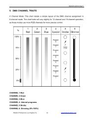
<strong>Vision</strong> <strong>Scan</strong> <strong>250</strong>10. DMX Channel Traits:The chart below details the channel layout for 14 DMX channels (default).In 8bit mode the “Pan Fine” and “Tilt Fine” channels are not used, thus converting thefixture into a 12 channel DMX fixture.CHANNEL 1: Pan Movement (max. 180°)CHANNEL 2: 16bit Pan Movement (pan fine)CHANNEL 3: Tilt Movement (max. 50°)CHANNEL 4: 16bit Tilt Movement (tilt fine)CHANNEL 5: Color WheelCHANNEL 6: Rotating Gobo WheelCHANNEL 7: Gobo Index, Gobo Rotation Speed/DirectionCHANNEL 8: Fixed Gobo WheelCHANNEL 9: 3-Facet Prism ControlCHANNEL 10: Focus ControlCHANNEL 11: Strobe (0-13Hz), and Shutter close/open function + random strobeCHANNEL 12: DimmerCHANNEL 13: Speed pan/tilt movement, blackout selectionCHANNEL 14: Special (Auto program control + lamp on, motor reset, lamp switch off)©<strong>Elation</strong> <strong>Professional</strong>® 38 <strong>Vision</strong> <strong>Scan</strong> <strong>250</strong>
<strong>Vision</strong> <strong>Scan</strong> <strong>250</strong>DMX channel function and values:Channel 1 - PAN movement 8bit:Channel 2 – Pan fine 16bit:Channel 3 - TILT movement 8bit:Channel 4 – Tilt fine 16bit:Channel 5 - Color Wheel :0-13 Open / White14-27 Red28-41 Blue42-55 Green56-69 Dark Yellow70-83 Magenta84-97 Orange98-111 UV filter112-127 Pink128-187 Forwards rainbow effect from fast to slow188-193 No rotation194-255 Backwards rainbow effect from slow to fastChannel 6 - Rotating gobos, cont. rotation :0-9 Open10-19 Rot. Gobo 120-29 Rot. Gobo 230-39 Rot. Gobo 340-49 Rot. Gobo 450-59 Rot. Gobo 560-69 Rot. Gobo 670-89 Gobo 1 shake slow to fast90-109 Gobo 2 shake slow to fast110-129 Gobo 3 shake slow to fast130-149 Gobo 4 shake slow to fast150-169 Gobo 5 shake slow to fast170-189 Gobo 6 shake slow to fast190-255 Rot. Gobo Wheel CW Rotation slow to fast©<strong>Elation</strong> <strong>Professional</strong>® 39 <strong>Vision</strong> <strong>Scan</strong> <strong>250</strong>
<strong>Vision</strong> <strong>Scan</strong> <strong>250</strong>Channel 7 - Rotating Gobo Index, Rotating Gobo Rotation :0-127 Gobo Indexing128-187 CW Gobo Rotation from fast to slow188-193 No rotation194-255 CCW Gobo Rotation from slow to fastChannel 8- Fixed Gobos :0-13 Open14-27 Gobo 128-41 Gobo 242-55 Gobo 356-69 Gobo 470-83 Gobo 584-97 Gobo 698-111 Gobo 7112-127 Gobo 1 shake slow to fast128-143 Gobo 2 shake slow to fast144-159 Gobo 3 shake slow to fast160-175 Gobo 4 shake slow to fast176-191 Gobo 5 shake slow to fast192-207 Gobo 6 shake slow to fast208-223 Gobo 7 shake slow to fast224-255 Gobo Wheel rotation from slow to fastChannel 9- 3 facet rotating prism, Prism / Gobo macros:0-3 Open4-63 Forwards rotation from fast to slow64-67 No rotation68-127 Backwards rotation from slow to fast128-135 Macro 1136-143 Macro 2144-151 Macro 3152-159 Macro 4160-167 Macro 5168-175 Macro 6176-183 Macro 7184-191 Macro 8192-199 Macro 9200-207 Macro 10208-215 Macro 11©<strong>Elation</strong> <strong>Professional</strong>® 40 <strong>Vision</strong> <strong>Scan</strong> <strong>250</strong>
<strong>Vision</strong> <strong>Scan</strong> <strong>250</strong>216-223 Macro 12224-231 Macro 13232-239 Macro 14240-247 Macro 15248-255 Macro 16Channel 10 – Focus :0-255 Continuous adjustment from far to nearChannel 11 - Shutter, strobe:0-31 Shutter closed32-63 No function (shutter open)64-95 Strobe effect slow to fast96-127 No function (shutter open)128-159 Pulse-effect in sequences160-191 No function (shutter open)192-223 Random strobe effect slow to fast224-255 No function (shutter open)Channel 12 - Dimmer (intensity):0-255 Intensity 0 to 100%Channel 13 - Speed pan/tilt movement:0-4 Max speed5-225 Max to min speed226-235 Blackout by movement236-245 Blackout by all wheel changing246-255 No functionChannel 14– Lamp on/off, reset, internal programs:0-19 Color Change Normal (Solid Colors Only)20-39 Enable Split Colors40-59 Lamp on60-79 Lamp switch off80-84 All motor reset85-87 <strong>Scan</strong> motor reset88-90 Colors motor reset91-93 Gobo motor reset94-96 Shutter & Dimmer motor reset97-99 Other motor reset©<strong>Elation</strong> <strong>Professional</strong>® 41 <strong>Vision</strong> <strong>Scan</strong> <strong>250</strong>
<strong>Vision</strong> <strong>Scan</strong> <strong>250</strong>100-119 Internal program 1120-139 Internal program 2140-159 Internal program 3160-179 Internal program 4180-199 Internal program 5200-219 Internal program 6220-239 Internal program 7240-255 Auto program by music©<strong>Elation</strong> <strong>Professional</strong>® 42 <strong>Vision</strong> <strong>Scan</strong> <strong>250</strong>
<strong>Vision</strong> <strong>Scan</strong> <strong>250</strong>11. ERROR CODES:When power is applied, the unit will automatically enter a “reset/test” mode. This modebrings all the internal motors to a home position. If there is an internal problem with one ormore of the motors an error code will flash in the display in the form of “XXer” were as XXwill represent a function number. For example, when the display shows “02Er,” it meansthere is some type of error with the channel 2 motor. If there are multiple errors during thestart-up process they will all flash in the display. For example: if the fixtures has errors onchannel 1, channel 2, and channel 5 all at the same time, you will see the error message“01Er”, “02Er,” and ”05Er” flash repeated 5 times.If an error does occur during the initial start-up procedure the fixture will self-generate asecond reset signal and try to realign all the motors and correct the errors, if the errorpersist after a second attempt a third attempt will be made.If after a third attempt all the errors have not been corrected the fixture will make thefollowing determinations: 1) 3 or more errors - The fixture cannot function properly withthree or more errors therefore the fixture will place itself in a stand-by mode untilsubsequent repairs can be made. 2) Less than 3 errors - The fixture has less than 3 errors,therefore most other functions will work properly. The fixture will attempt to operate normallyuntil the errors can be correct by a technician. The errors in question will remain flashing inthe display as a reminder of internal errors.05Er - Color-wheel error:The color wheel is not located in the default position after start-up or after a resetcommand.This message will appear after a fixture reset if the color wheel’s magnetic-indexing circuitmalfunctions (sensor failed or magnet is missing) or there is a stepper motor failure(defective motor or a defective motor IC drive on the main PCB).06Er - Rotating gobo-wheel error:The gobo-wheel is not located in the default position after start-up or after a reset©<strong>Elation</strong> <strong>Professional</strong>® 43 <strong>Vision</strong> <strong>Scan</strong> <strong>250</strong>
<strong>Vision</strong> <strong>Scan</strong> <strong>250</strong>command.This message will appear after a fixture reset if the gobo wheel’s magnetic-indexing circuitmalfunctions (sensor failed or magnet is missing) or there is a stepper motor failure(defective motor or a defective motor IC drive on the main PCB).07Er - Rotating gobo indexing error:The gobo is not located in the default position after start-up or after a reset command.This message will appear after a fixture reset if the gobo positioning magnetic-indexingcircuit malfunctions (sensor failed or magnet is missing) or there is a stepper motor failure(defective motor or a defective motor IC drive on the main PCB).08Er - Fix Gobo-wheel errorThis message will appear after the reset of the fixture if the magnetic-indexing circuitmalfunctions (sensor failed or magnet missing) or the stepping-motor is defective (or itsdrive circuit on the main PCB). The fix gobo wheel is not located in the default position afterthe reset.09Er - Prism-wheel errorThis message will appear after the reset of the fixture and if the magnetic-indexing circuitmalfunctions (sensor failed or magnet missing) or the stepping-motor is defective (or itsdriver circuit on the main PCB). The rotating gobo motor is not located in the defaultposition after the reset.10Er - Focus-errorThis message will appear after the reset of the fixture and if the magnetic indexing circuitmalfunctions (sensor failed or magnet missing) or the stepping-motor is defective (or itsdriver circuit on the main PCB). The focus motor is not located in the default position afterthe reset.©<strong>Elation</strong> <strong>Professional</strong>® 44 <strong>Vision</strong> <strong>Scan</strong> <strong>250</strong>
<strong>Vision</strong> <strong>Scan</strong> <strong>250</strong>12. CLEANING AND MAINTENANCEThe following points have to be considered during the inspection:1. All screws for installing the devices or parts of the device have to be tightlyconnected and must not be corroded.2. There must not be any deformations on the housing, color lenses, fixations andinstallation spots (ceiling, suspension, trussing).3. Mechanically moved parts must not show any traces of wearing and must not rotatewith unbalances.4. The electric power supply cables must not show any damage, material fatigue orsediments.Further instructions depending on the installation spot and usage have to be adhered by askilled installer and any safety problems have to be removed.Disconnect from mains before starting maintenance operation.We recommend a frequent cleaning of the device. Please use a moist, lint- free cloth. Neveruse alcohol or solvents.There are no user serviceable parts inside this fixture with the exception of the lamp.Please refer all other service issues to an authorized <strong>Elation</strong> service technician.Should you need any spare parts, please order genuine parts from your local dealer.©<strong>Elation</strong> <strong>Professional</strong>® 45 <strong>Vision</strong> <strong>Scan</strong> <strong>250</strong>
<strong>Vision</strong> <strong>Scan</strong> <strong>250</strong>13. 2-YEAR LIMITED WARRANTYA. <strong>Elation</strong> <strong>Professional</strong>® hereby warrants, to the original purchaser, <strong>Elation</strong> <strong>Professional</strong>®products to be free of manufacturing defects in material and workmanship for a period oftwo years, (730 days) from the date of purchase. This warranty shall be valid only if theproduct is purchased within the United States of America, including possessions andterritories. It is the owner’s responsibility to establish the date and place of purchase byacceptable evidence, at the time service is sought.B. For warranty service, send the product only to the <strong>Elation</strong> <strong>Professional</strong>® factory. Allshipping charges must be pre-paid. If the requested repairs or service (including partsreplacement) are within the terms of this warranty, <strong>Elation</strong> <strong>Professional</strong>® will pay returnshipping charges only to a designated point within the United States. If the entire instrumentis sent, it must be shipped in its original package. No accessories should be shipped withthe product. If any accessories are shipped with the product, <strong>Elation</strong> <strong>Professional</strong>® shallhave no liability what so ever for loss of or damage to any such accessories, nor for thesafe return thereof.C. This warranty is void if the serial number has been altered or removed; if the product ismodified in any manner which <strong>Elation</strong> <strong>Professional</strong>® concludes, after inspection, affects thereliability of the product; if the product has been repaired or serviced by anyone other thanthe <strong>Elation</strong> <strong>Professional</strong>® factory unless prior written authorization was issued to purchaserby <strong>Elation</strong> <strong>Professional</strong>®; if the product is damaged because not properly maintained as setforth in the instruction manual.D. This is not a service contract, and this warranty does not include maintenance, cleaningor periodic check-up. During the period specified above, <strong>Elation</strong> <strong>Professional</strong>® will replacedefective parts at its expense, and will absorb all expenses for warranty service and repairlabor by reason of defects in material or workmanship. The sole responsibility of <strong>Elation</strong><strong>Professional</strong>® under this warranty shall be limited to the repair of the product, orreplacement thereof, including parts, at the sole discretion of <strong>Elation</strong> <strong>Professional</strong>®. Allproducts covered by this warranty were manufactured after January 1, 1990, and bare©<strong>Elation</strong> <strong>Professional</strong>® 46 <strong>Vision</strong> <strong>Scan</strong> <strong>250</strong>
<strong>Vision</strong> <strong>Scan</strong> <strong>250</strong>identifying marks to that effect.E. <strong>Elation</strong> <strong>Professional</strong>® reserves the right to make changes in design and/or improvementsupon its products without any obligation to include these changes in any productstheretofore manufactured.F. No warranty, whether expressed or implied, is given or made with respect to anyaccessory supplied with products described above. Except to the extent prohibited byapplicable law, all implied warranties made by <strong>Elation</strong> <strong>Professional</strong>® in connection with thisproduct, including warranties of merchantability or fitness, are limited in duration to thewarranty period set forth above. And no warranties, whether expressed or implied, includingwarranties of merchantability or fitness, shall apply to this product after said period hasexpired. The consumer’s and or Dealer’s sole remedy shall be such repair or replacementas is expressly provided above; and under no circumstances shall <strong>Elation</strong> <strong>Professional</strong>® beliable for any loss or damage, direct or consequential, arising out of the use of, or inability touse, this product.G. This warranty is the only written warranty applicable to <strong>Elation</strong> <strong>Professional</strong>® Productsand supersedes all prior warranties and written descriptions of warranty terms andconditions heretofore published.©<strong>Elation</strong> <strong>Professional</strong>® 47 <strong>Vision</strong> <strong>Scan</strong> <strong>250</strong>
<strong>Vision</strong> <strong>Scan</strong> <strong>250</strong>14. Photometric Data:15. Gobos:©<strong>Elation</strong> <strong>Professional</strong>® 48 <strong>Vision</strong> <strong>Scan</strong> <strong>250</strong>
<strong>Vision</strong> <strong>Scan</strong> <strong>250</strong>16. Dimensional Drawings:©<strong>Elation</strong> <strong>Professional</strong>® 49 <strong>Vision</strong> <strong>Scan</strong> <strong>250</strong>
<strong>Vision</strong> <strong>Scan</strong> <strong>250</strong>17. Circuit Schematic©<strong>Elation</strong> <strong>Professional</strong>® 50 <strong>Vision</strong> <strong>Scan</strong> <strong>250</strong>
<strong>Vision</strong> <strong>Scan</strong> <strong>250</strong>18. TECHNICAL SPECIFICATIONSPower supply (user selectable):_98VAC,50Hz;_120VAC,50Hz;_208VAC,50Hz;_220VAC,50Hz;_230VAC,50Hz;_240VAC,50Hz; or_98VAC,60Hz;_120VAC,60Hz;_208VAC,60Hz;_220VAC,60Hz;_230VAC,60Hz;_240VAC,60Hz;Power consumption: Max. 400wLamp: MSD <strong>250</strong>/2 GY9.5 socket, Metal Halide (<strong>250</strong>w, 8500˚K, 3000hrs, 18,000lm)Fuse: GMA <strong>250</strong>v/10AMotors: 10 micro motorsPan Movement: 180˚ in 2.0 sec.Tilt Movement: 50˚ in 1.5 sec.Focus: Motor driven focus from near to farDMX Drive: Standard DMX-512, 3 pole XLR; [+] = Pin 3 [-] = Pin 2 [Ground] = Pin 1.Colors: 8 Dichroic colors plus white. (Size: 34mm diameter/1mm width)Gobos: 13 Total1. Wheel 1: 6 indexable, rotating, interchangeable plus open (Size: 27mmdiameter/24mm viewable/1mm width)2. Wheel 2: 7 static gobos plus spot (Size: 27mm diameter/24mm viewable/1mmwidth)DMX Channels: 14 (16bit ~ default) / 12 (8bit)Beam angle: 18˚Packing dimensions: (92x48x43) cmNet weight: 22 KGSGross weight: 25 KGSPlease Note: Specifications and improvements in the design of this unit and this manual are subjectto change without any prior written notice.©<strong>Elation</strong> <strong>Professional</strong>® 51 <strong>Vision</strong> <strong>Scan</strong> <strong>250</strong>
<strong>Vision</strong> <strong>Scan</strong> <strong>250</strong><strong>Elation</strong> <strong>Professional</strong>4295 Charter StreetLos Angeles, CA. 90058323-582-3322 / 323-582-3108 faxwww.<strong>Elation</strong>Lighting.com /Info@<strong>Elation</strong>Lighitng.com©<strong>Elation</strong> <strong>Professional</strong>® 52 <strong>Vision</strong> <strong>Scan</strong> <strong>250</strong>