RC953-8FE16E1 Inverse Multiplexing Ethernet Gateway User manual
RC953-8FE16E1 Inverse Multiplexing Ethernet Gateway User manual
RC953-8FE16E1 Inverse Multiplexing Ethernet Gateway User manual

Create successful ePaper yourself
Turn your PDF publications into a flip-book with our unique Google optimized e-Paper software.
<strong>RC953</strong>-<strong>8FE16E1</strong><strong>Inverse</strong> <strong>Multiplexing</strong> <strong>Ethernet</strong><strong>Gateway</strong><strong>User</strong> <strong>manual</strong>Raisecom Technology Co., Ltd(06/2006)
Contents1. Cautions.............................................................................................................. 12. Overview............................................................................................................. 22.1. Main features ........................................................................................... 22.2. Part number specification......................................................................... 32.3. Dimension ................................................................................................ 33. Parameters ......................................................................................................... 43.1. Basic configuration................................................................................... 43.2. <strong>Ethernet</strong> interface parameters.................................................................. 43.3. E1 interface parameters........................................................................... 43.4. CONSOLE interface parameters.............................................................. 53.5. SNMP network management interface parameter ................................... 53.6. Power supply ........................................................................................... 53.7. Ambience ................................................................................................. 54. How to use.......................................................................................................... 64.1. Front panel explanation............................................................................ 64.2. Rear panel explanation ............................................................................ 75. Typical application .............................................................................................. 96. Installation & Preparation.................................................................................. 106.1. Preparation before Installation ............................................................... 106.2. Installation.............................................................................................. 106.2.1. Cable preparation.......................................................................... 106.2.2. Connect the fast <strong>Ethernet</strong> port .......................................................116.2.3. Connect the SNMP network management port ..............................116.2.4. Connect the CONSOLE port ..........................................................116.2.5. Power on........................................................................................116.2.6. Service configuration..................................................................... 127. Q & A ................................................................................................................ 138. Appendix A: How to make CONSOLE cable..................................................... 149. Appendix B: Abbreviations................................................................................ 15
Raisecom Technology Co., Ltd1. CautionsPlease read the following notices carefully beforeinstalling and using the device, Raisecom does notrespond to any loss that caused by violating safetynotice.This series product is integrated device that hasprecise elements, please avoid violent shakes andimpacts, and do not disassemble or maintain thedevice yourself. If it is required, please do it under theguide of our technical staff following in the steps ofanti static. Please contact us if there is any need.There must be grounding protection for the sake ofsafety; do not disassemble the device yourself, weregard it as you waiver your rights of repair guarantee.1
Raisecom Technology Co., Ltd2. Overview<strong>RC953</strong>-<strong>8FE16E1</strong> is an <strong>Inverse</strong> <strong>Multiplexing</strong> <strong>Ethernet</strong> <strong>Gateway</strong> that delivers <strong>Ethernet</strong>services over existing TDM transportation network. It can be deployed in central site foraggregating subscribers or in customer premises enabling <strong>Inverse</strong> <strong>Multiplexing</strong> forenlarging much more bandwidth.<strong>RC953</strong>-<strong>8FE16E1</strong> provides 8 <strong>Ethernet</strong> ports and 16 E1 ports (both balanced andunbalanced) for subscribers and functions as a bridge between IP-based network andleased circuits.Additionally its advanced features such as automatic E1 link adjustment,<strong>Ethernet</strong> port trunking (Link Aggregation for redundant <strong>Ethernet</strong> Access) and redundantpower supply provide our carriers a cost-effective, flexible and reliable solution forhigh-quality <strong>Ethernet</strong> Service delivery by using TDM network resources.2.1. Main features• Provide 16 E1 interfaces and the E1 working mode can be Single E1 Mode and<strong>Inverse</strong> <strong>Multiplexing</strong> Mode;• Provide 8 fast <strong>Ethernet</strong> interfaces, which support auto-negotiation, auto-MDI/MDIX,10M/100M, half/full duplex and IEEE802.3x flow control;• HDLC-over-E1 encapsulation• In single E1 mode:• Support both framed and unframed E1 mode• Only one E1 link in each transmission channel• With RC952 in remote sites in hub-and-spoke topology• In E1 <strong>Inverse</strong> <strong>Multiplexing</strong> mode:• Adopt frame-interleave multiplexing to realize the transportation of <strong>Ethernet</strong> overmultiple E1• With <strong>RC953</strong>-FE4E1/8E1 in remote sites in hub-and-spoke topology• E1 link sequence auto-sensing• The maximum relative latency of E1 line is +/-16ms• Automatically adjust the E1 link capacity of transmission channel if one or moreE1 link fails• Only support framed E1 (PCM31, FAS+CRC4 by default), CRC auto-negotiationand is configurable• <strong>Ethernet</strong> switching function:• 4096 MAC address• Transparently forward BPDU, GMRP, GVRP and IGMP packets• Maximum Transmission Unit: 1536 bytes• <strong>Ethernet</strong> port trunking (Link Aggregation for redundant <strong>Ethernet</strong> Access)2
Raisecom Technology Co., Ltd• E1 loop back and BERT function• Complete E1 line indicators on front panel• E1 interface type: 2 DB37 for both balanced and unbalanced interfaces• SNMP, CONSOLE and Telnet management (any of the 8 fast <strong>Ethernet</strong> can be SNMPnetwork management interface) and support local and remote field firmware upgrade.• 1U chassis and can be installed in 19’’ rack• Redundant power supply• Power consumption
Raisecom Technology Co., Ltd3. Parameters3.1. Basic configuration• Main circuit: 8 fast <strong>Ethernet</strong> ports, 16 E1 ports.• Power supply: two power supply modules, 90-264V/AC or -36V- -72V/DC.• Management interface: CONSOLE, SNMP network management interface(utilize any of the 8 fast <strong>Ethernet</strong> ports).3.2. <strong>Ethernet</strong> interface parameters• Speed: 10/100M auto-negotiation• Connector: RJ-45• IEEE802.3 compliant• IEEE802.3x flow control• AUTO-MDI/MDIX3.3. E1 interface parameters• 75ohm unbalanced or 120ohm balanced E1 connector.• 16 E1 ports, the first 8 E1 ports utilize one DB37 and the second 8 E1 portsutilize another DB37.• Bit rate: 2048Kbps±50ppm.• Line coding: HDB3.• Input impedance: 75ohm unbalanced.• Electric characteristic: ITU-T G.703 compliant.• Frame structure: ITU-T G.704 compliant• Jitter: ITU-T G.823 compliant.• In single E1 mode:• E1 interface supports both framed and unframed E1 mode and can beconfigured through software (unframed mode by default).• In framed E1 mode, support N*64k sub-rate access and FAS (PCM31without CRC4), FAS+CRC4 (PCM31 with CRC4), FAS+CAS (PCM30without CRC4) and PAS+CRC4+CAS (PCM30 with CRC40).• In E1 <strong>Inverse</strong> <strong>Multiplexing</strong> mode:• Adopt frame-interleave multiplexing to realize the transportation of <strong>Ethernet</strong> overmultiple E1.• E1 wire sequence auto-sensing• The maximum relative latency of E1 line is +/-16ms• Automatically adjust the E1 link capacity of transmission channel if one or moreE1 link fails• Only support framed E1 (PCM31, FAS+CRC4 by default), CRC auto-negotiation4
Raisecom Technology Co., Ltdand is configurable• There are three status indicators for each E1 circuit:• LOS: Loss of Signal (local)• LAL: local E1 general alarm, including AIS(alarm indication signal), LOF( Loss ofFrame), CRC(Cyclic Redundancy Check)• RAL: remote E1 alarm, including LOS, AIS, LOF, CRC• Local and remote E1 loop back• E1 BERT (bit error rate tester) function• Traffic counter provides an effective E1 link monitoring by statistics collection of Rx,TX, total and error packets amount on E1 port.• 4M Bytes buffer for each <strong>Ethernet</strong> port to avoid packet loss3.4. CONSOLE interface parameters● Connector type: RJ-45● RS232 compliant● Rate: 9600bps3.5. SNMP network management interface parameter● Utilize one of the 8 fast <strong>Ethernet</strong> ports, please refer to chapter 3.23.6. Power supply● Redundant power supply.● Voltage range: -48VDC, –36V - -72V220VAC, 90V- 264V● Power consumption:
Raisecom Technology Co., Ltd4. How to use4.1. Front panel explanation<strong>RC953</strong>-<strong>8FE16E1</strong>1 2 3 4 5 678 9Figure 4-1 FrontTable 4-1 Explanation of <strong>RC953</strong>-<strong>8FE16E1</strong> front panelNo.ExplanationIndicatorcolorDescription1 GroundingSYSandGreenSYS, Flashing indicates CPU work normally.2PWRPWR, ON indicates equipment is powered on.indicatorPWR1GreenPWR1, ON indicates the first power supply works normallyandPWR2, ON indicates the second power supply works normally.PWR2Explanation of PWR, PWR1and PWR2 combination:PWR PWR1 PWR2ExplanationON ON ON The two power supply modules and main circuitworks normally.ON ON OFF The first power supply works normally, the second3works abnormally and the main circuit worksnormally.ON OFF ON The first power supply works abnormally, the secondworks normally and the main circuit works normally.OFF ON ON The first power supply works normally, the secondworks normally but the main circuit worksabnormally.OFF ON OFF The first power supply works normally, the secondworks abnormally but the main circuit worksabnormally.6
Raisecom Technology Co., Ltd456789CONSOLE<strong>Ethernet</strong>portindicator1-8 E1indicator1-8 E1connector9-16 E1indicator9-16 E1connectorGreen/orangeRedRedOFF OFF ON The first power supply works abnormally, the secondworks normally but the main circuit worksabnormally.OFF OFF OFF Not powered on or neither of the power supplymodule works normally.Local management port which connects to management PC1-8 fast <strong>Ethernet</strong> ports. And each port has two indicators: LNK/ACT (green)and 100M indicator (orange).LNK/ACT, flashing indicates data is being received;100M, ON indicates the speed of fast <strong>Ethernet</strong> is 100M and OFF indicates10M.Each E1 circuit has three indicators, from top to bottom are:(Top) LOS: Loss of Signal (local).(Middle) LAL: local general alarm, including AIS (alarm indication signal),LOF (loss of frame), CRC (cyclic redundancy check).(Bottom) RAL: remote general alarm, including LOS, AIS, LOF, CRC.*note: when both LOS and LAL are ON at the same time, this indicates GIDalarm.DB37 connector which connects with special cable.Each E1 circuit has three indicators, from top to bottom are:(Top) LOS: Loss of Signal (local).(Middle) LAL: local general alarm, including AIS (alarm indication signal),LOF (loss of frame), CRC (cyclic redundancy check).(Bottom) RAL: remote general alarm, including LOS, AIS, LOF, CRC.*note: when both LOS and LAL are ON at the same time, this indicates GIDalarm.DB37 connector which connects with special cable.4.2. Rear panel explanationONOFF12Figure 4-2 rear panel of <strong>RC953</strong>-<strong>8FE16E1</strong>7
Raisecom Technology Co., LtdTable 4-2: explanation of <strong>RC953</strong>-<strong>8FE16E1</strong> rear panelNumber12ExplanationPower supplyswitch for thedevicePower supplyconnectorON/OFF.DescriptionTwo types, AC and DC.8
Raisecom Technology Co., Ltd5. Typical applicationFigure 5-1 point-to-point topologyFigure 5-2 point-to-multi point topology9
Raisecom Technology Co., Ltd6. Installation & Preparation6.1. Preparation before InstallationPlease check if the models and part numbers are in consistence first, and also check if theequipments are damaged. There must be drying process if the equipment is damped.Please follow the following steps when install and use this equipment:● Carefully read this <strong>manual</strong>● Prepare all kinds of the cable. Ensure that they are not short-circuited. Refer toAppendix A for cable making.● Fix and install the equipment● Connect E1 cable● Configure the equipment according to the configuration guide● Use the equipment correctly6.2. Installation6.2.1. Cable preparationThe following cables need to be prepared:Table 6-1 Cable specification for <strong>RC953</strong>-<strong>8FE16E1</strong> connectorsConnectorCable specification10/100Mbps Electrical<strong>Ethernet</strong> connector(SNMP managementconnector)Connector cable forE1 (the first 8 E1utilize one DB37connector and thesecond 8 E1 utilizeone DB37 connector)CONSOLE connectorPowerconnectorsupplyCat. 5 100Base-T UTP, and the maximumlength is 100m (prepared by customers)Please order the 2 cables separatelyFor 75ohm unbalanced E1 connector: one end ofthe cable is DB37 and the other end are 875ohm unbalanced BNC connectors;For 120ohm balanced E1 connector: one end ofthe cable is DB37 and the other end are 8balanced RJ-45 connectors;Provide one CONSOLE cable.Please refer to the appendix for how to makeCONSOLE cable.AC power supply: provide one AC power supplycable.DC power supply: provide one DC power supplycable.10
Raisecom Technology Co., Ltd6.2.2. Connect the fast <strong>Ethernet</strong> portConnect one end of the Cat. 5 UTP cable with <strong>Ethernet</strong> router/switch and one end of thecable with the fast <strong>Ethernet</strong> port of <strong>RC953</strong>-<strong>8FE16E1</strong>. The LNK/ACT indicator will be ONafter correct connection.6.2.3. Connect the SNMP network management portConnect one end of the Cat. 5 UTP cable with management PC and one end of the cablewith the fast <strong>Ethernet</strong> port of <strong>RC953</strong>-<strong>8FE16E1</strong>. The LNK/ACT indicator will be ON aftercorrect connection.6.2.4. Connect the CONSOLE port●●●Connect the RJ-45 connector of CONSOLE cable with the CONSOLE port on thefront panel.Connect the DB9 connector of CONSOLE cable with the PC serial port.Start the HyperTerminal program and configure the COM port properties as follows:●Configure <strong>RC953</strong>-<strong>8FE16E1</strong> according to software configuration guide6.2.5. Power onIf power supply is DC –48V, first connect middle end to PGND. Turn off Power Supply,11
Raisecom Technology Co., Ltdconnect “-48V” end with the lower electric level cable, “0V” end with higher electric levelcable. Make sure no reverse connection, or no short circuited, and then turn on power.When Power Supply is turned on, the PWR indicator should be ON.6.2.6. Service configurationPlease refer to the command notebook and configuration guide of <strong>RC953</strong>-<strong>8FE16E1</strong> forthe service configuration.12
Raisecom Technology Co., Ltd7. Q & AIf there are any problems during installation and using, try the following proposals. If theproblems still can not be solved, please contact distributors/agents for help.● If PWR, PWR1 and PWR2 are all OFFPlease check if power supply cable is connected and then check if the Power SupplyBoard works normally*Explanation of PWR, PWR1and PWR2 combination:PWR PWR1 PWR2ExplanationON ON ON The two power supply modules and main circuit works normally.ON ON OFF The first power supply works normally, the second one works abnormallyand the main circuit works normally.ON OFF ON The first power supply works abnormally, the second one works normally andthe main circuit works normally.OFF ON ON The first power supply works normally, the second one works normally but themain circuit works abnormally.OFF ON OFF The first power supply works normally, the second one works abnormally butthe main circuit works abnormally.OFF OFF ON The first power supply works abnormally, the second one works normally butthe main circuit works abnormally.OFF OFF OFF Not powered on or neither of the power supply module works normally.● E1 LOS indicator is ONAnswer: Loss of receiving signal occurs at e1 port. Check whether E1 cable is connectedcorrectly; if there is still LOS alarm please change the E1 cable otherwise there issomething wrong with the equipment.● <strong>Ethernet</strong> LINK indicator OFFAnswer: please check if the UTP cable is broken off first and then check if the equipmentthat connects with <strong>RC953</strong>-<strong>8FE16E1</strong> works normally. Please make sure that the correct<strong>Ethernet</strong> cable is used.● Packets loss during traffic transmittingAnswer: Firstly, please check the connection of <strong>Ethernet</strong> and E1 cables, and make surethe Channel, Map and DIP-switch configuration is correct.Secondly, please avoid loops of <strong>Ethernet</strong> interfaces. For example, more than one<strong>Ethernet</strong> interfaces can not connect to a same <strong>Ethernet</strong> switch if they are not configuredas Trunk interfaces.13
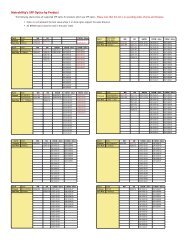
Raisecom Technology Co., Ltd8. Appendix A: How to make CONSOLE cablePin definitions:RJ45 pins Function DS9 pins1 NC -2 DSR# 63 RxD 34 GND 55 GND 56 TxD 27 DTR# 48 NC -“-” indicates the relative RJ45 pin is not connected (NC).DB9 pins which are not in the list are not connected (NC).14
Raisecom Technology Co., Ltd9. Appendix B: AbbreviationsEoPDHPDH<strong>Ethernet</strong> over PDHPseudo-synchronous Digital Hierarchy.15
Raisecom Technology Co., Ltd@2006 Raisecom Technology Co., Ltd.All trademarks are the property of their respective owners.Technical information may be subject to change without prior notification.16