Weather louvres serie 200 - Koolair
Weather louvres serie 200 - Koolair
Weather louvres serie 200 - Koolair
- No tags were found...

You also want an ePaper? Increase the reach of your titles
YUMPU automatically turns print PDFs into web optimized ePapers that Google loves.
<strong>serie</strong>s100-<strong>200</strong>
3Table of ContentsPage100 Series Regulating Dampers __________________________________________________ 4Overview ______________________________________________________________________ 5Graphs ________________________________________________________________________ 6<strong>200</strong> Series Outside Air Intake Louvers _____________________________________________ 8Overview ______________________________________________________________________ 9Selection Table and Dimensions ____________________________________________________ 10Load Loss Graphs _______________________________________________________________ 11TAC -<strong>200</strong> Series Outside Air Intake Louvers _________________________________________ 12Overall Dimensions ______________________________________________________________ 13Load Loss Graphs _______________________________________________________________ 14Overpressure Damper 230 SP ____________________________________________________ 16Example of Selection and Dimensions ________________________________________________ 17
4100 Series Regulating DampersDescriptionRegulating damper with opposed and aerodynamic vanes,manufactured in aluminium (AOBD-102-E). The body ofthe damper has built-in air tight gaskets all around itsinner perimeter to ensure a tight seal. The movement ofthe vanes is ensured by means of gears, achieving a properfriction, with manual or motor-driven operation.Vanes are available with 75 and 100 mm vane axisdistances, to complete the entire range of standard ductdimensionsManually Operated Model AOBD-102-EFlat parallel-vane (SOBD-105) or opposite-vane (SOBD-106) regulating dampers, manufactured in galvanized steelsheet, manually operated or ready for motor-driveoperation. Actuation is carried out through nylon bearings.They incorporate air tight gaskets on the upper and lowerlongitudinal sides of the vanes to ensure a tight seal.Dampers with leak proof gaskets incorporated on thedamper's vertical profiles can be supplied upon request.FinishesIn natural aluminium (AOBD) or in galvanized steelsheet (SOBD / SPBD).Manually Operated Model AOBD-102-E double-length (L>1<strong>200</strong>)Overall dimensionsSee page 5. Rest of dimensions according to thedrawings on the left.MountingIt is mounted directly onto a duct, supported on thedamper border flanges or framing.Double Damper at 90° Model AOBD-102-E-ND90All the damper's operating mechanisms are installed withinthe U frame. This way, the air can flow freely and itfacilitates its installation in closed ducts. The mechanismsas well as the mounting hardware used are made ofcorrosion resistant materials.CodingAOBD-102-ESPBD-105SOBD-106LxH (mm)-+MM+MTAluminium opposed-vane regulating damper.Sheet metal parallel-vane regulating damper.Sheet metal opposed-vane regulating damper.Length x height dimensions (mm).Ready to be motorized.Manually operated.Servomotor driven (indicate what type in the order).Other constructionsPossibility of manufacturing two solidly joined dampersat 90°, to obtain the same degree of aperture/closing forboth dampers (models AOBD-102-E-ND90 or SOBD105-ND90). For the same application, it is also available forparallel mounting.
5Models. DimensionsThe dimensions indicated below are standard for regulating dampers. Regarding the length and height, they can be manufacturedusing intermediate dimensions, with 50mm vane axis distances.Regulating damper model AOBD-102-EL <strong>200</strong> 300 400 500 600 700 800 900 1000 1<strong>200</strong> 1500 <strong>200</strong>0 3000H100150<strong>200</strong>25030050080010001<strong>200</strong>1500Model AOBD-102-E<strong>200</strong>0AOBD-102-EModel AOBD-102-E double length (L>1<strong>200</strong>)Regulating damper model SPBD-105 and SOBD-106L <strong>200</strong> 300 400 500 600 700 800 900 1000 1<strong>200</strong> 1500 <strong>200</strong>0 3000H160288416544672800928105611841312Model SPBD-105 / SOBD-106SPBD-105SOBD-106Model SPBD-105 / SOBD-106 double length (L>1<strong>200</strong>)
6Load loss and air tightness graphs for aluminium regulating dampersApertureLoad Loss in Pa25%Aperture50%Load Loss in PaCompletely closedManual operationCompletely closedTurn moment 60 Kg x cm.Motor-drivenAperture75%Aperture100%LOAD LOSSTYPE AOBD-102-EOpposed aerodynamic vanesTYPE AOBD-102-EOpposed aerodynamic vanesLeaks % of maximum flowFront velocity: m/s.Note: The air leak at damper AOBD-102-E is not greater than 2% in the closed position, with a static pressure of 1250 Pa.Example of SelectionKnowing the air flow to be regulated by the damper, and using, for example, a front velocity of 6 m/s, the front surface of thedamper can be obtained.This can be calculated using the following formula:A f(m 2 ) = q v(m 3 /h) / V f(m/s) • 3600With an air flow rate (qv) of 12,000 m3/h, we obtain:A f(m 2 ) = 10.800 / 6 • 3600= 0,50 m 2This would lead to an AOBD-102-E damper with a 100 x 500 equivalent section with a load loss of 13 Pa for a 100%aperture.
7Load loss graphs for steel sheetregulating dampersAir tightness graphs for steel sheetregulating dampersTYPE SPBD-105LEAK GRAPH IN m3/h WITHOUT LEAK PROOF GASKETS FORPARALLEL AND OPPOSED VANE DAMPERSLoad loss in PaOpening 25%Opening 50%Opening 75%Opening 100%TYPE SPBD-105TYPE SOBD-106TYPE SOBD-106LEAK GRAPH IN m3/h WITH LEAK PROOF SEALS FORPARALLEL AND OPPOSED VANE DAMPERSLoad loss in PaDamper length in mm.Damper length in mm.1 Blade2 Blades3 Blades4 Blades5 Blades6 Blades7 Blades8 BladesFront velocity: m/s.Flow m 3 /hOpening 25%Opening 50%Opening 75%Opening 100%1 Blade2 Blades3 Blades4 Blades5 Blades6 Blades7 Blades8 BladesFront velocity: m/s.Flow m 3 /hTYPE SPBD-105TYPE SOBD-106Note: The air-tightness graphs for the steel sheet regulating dampers are based on a differential pressure of 250 Pa throughthe damper.
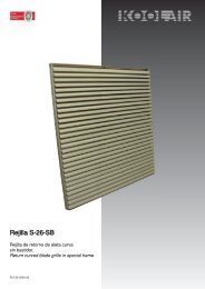
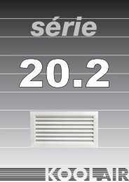
8<strong>Weather</strong> <strong>louvres</strong> <strong>serie</strong> <strong>200</strong>Description<strong>Weather</strong> louvre for intake or discharge, model 210 TAFinishesIn natural aluminium (without anodising).Special finishes available upon request.L x H68(L - 14) x (H - 14) 40(L+ 66) x (H + 66)210 TA<strong>Weather</strong> louvre for intake or discharge, constructed inextruded aluminium.Its design and blade shape avoid vision through thelouvre.It avoids penetration of rain water, snow, etc., since ithas been principally designed for outdoor installation. Itcan be provided with bird screen or insect screen.6L+ 66FixingThe <strong>louvres</strong> incorporate fasteners in the frame forinstallation.Upon request the frame can be delivered with holes forfixing by means of screws.H+ 66210TAwith birdscreenwith insectscreenModelAccessory(without indication a birdscreen will beprovided)Identification<strong>Weather</strong> <strong>louvres</strong> 210TA are used in : commercial andindustrial buildings, air handling units, transformerhouses, machine rooms, parkings, shelters, etc.LxH (mm)Dimensions of opening (width x height mm)
9General- As an accessory the weather <strong>louvres</strong> 210TA incorporate abirdscreen or an insect screen.Birdscreen Insect screenThe pressure loss of 210TA <strong>louvres</strong> for a given air flow rateand dimensions can be determined from the selectiontable in the following mannerAir flow rate......................... 5000 m 3 /hDimensions in mm (L x H)..... 1000 x 650Face velocity (V f) = 5.000 / (1000 x 650 en m 2 ) • 3600 =2,1 m/sPressure loss at intake for louvre with birdscreen:21Pa.Pressure loss at discharge for louvre with birdscreen:24Pa.12,5 x 12,5mm.1,6 x 1,6 mm.- Can be built as a single module upto maximumdimensions of 3000 x <strong>200</strong>0 mm (width x height). Forwidths above 1000 mm central reinforcements areincorporated as shown below.L < 1m.L >1m. < 2m.L >2m. < 3m.Example of selectionFor a known air flow rate which should pass through thelouvre at, for example, a velocity of 5 m/s (corresponding toapproximately 2 to 2.5 m/s face velocity), the louvredimensions can be obtained by using the quick selectiontable.Example : For 500 m 3 /h a 210TA of 1000 x 600 or other withequivalent areaObviously, the effective area will increase for higher height/length ratios, due to the inactive zones at the first and lastlouvre blades, i.e. the effective area of a 500 x 1000 mm(L x H) louvre will be higher than for a 1000 x 500 mm size.
10Quick selection table 210TAH L %free area 500 750 1.000 1.500 2.000 2.500 3.000air flow rate in m 3 /h150 23,40 360 540 720 1.080 1.440 1.800 2.160250 32,40 720 1.080 1.440 2.160 2.880 3.600 4.320300 37,40 1.080 1.620 2.160 3.240 4.320 5.400 6.480400 40,0 1.440 2.160 2.880 4.320 5.760 7.<strong>200</strong> 8.640450 42,10 1.800 2.700 3.600 5.400 7.<strong>200</strong> 9.000 10.800550 43,50 2.160 3.240 4.320 6.480 8.640 10.800 12.960650 44,50 2.520 3.780 5.040 7.560 10.080 12.600 15.100700 45,60 2.880 4.320 5.760 8.640 11.500 14.400 17.300800 46,30 3.240 4.860 6.500 9.750 13.000 16.250 19.500850 46,80 3.600 5.400 7.<strong>200</strong> 10.800 14.400 18.000 21.600900 47,30 3.960 5.950 7.950 11.900 15.900 19.800 23.8001000 47,80 4.600 6.900 9.<strong>200</strong> 13.800 18.400 23.000 27.560Standard dimensionsH L<strong>200</strong>300400500600700800900100011001<strong>200</strong>1300140015001600170018001900<strong>200</strong>0500 600 700 750 800 900 1000 1100 1<strong>200</strong> 1300 1400 1500 <strong>200</strong>0 2250 2500 2750 3000Note : Dimensions in width (L) may be varied upon request. The <strong>louvres</strong> can be provided in intermediate heightdimensions as multiples of 50 mm (e.g. 250, 350, 450 mm, etc...)
Pressure loss Pa11Graphs for pressure loss of 210TA210TA for intakeFace velocity m/s210TA for dischargePressure loss PaFace velocity m/sA.- LouvreB.- Louvre with birdscreenC.- Louvre with insect screen
12Circular weather <strong>louvres</strong> TAC-<strong>200</strong>Description<strong>Weather</strong> louvre, model TAC-<strong>200</strong>FinishesPainted in white RAL 9010.Special finishes available upon request.Insect screenBird screenTAC-<strong>200</strong>Circular weather louvre, constructed in extrudedaluminium.Its design and blade shape avoid vision through thelouvre.It avoids penetration of rain water, snow, etc., since ithas been principally designed for outdoor installation.Its circular shape makes it ideal for those installationswhere, for architectural reasons, conventional rectangular<strong>louvres</strong> are not acceptable.FixingThe louvre frame is provided with holes for fixing bymeans of screws.TAC-<strong>200</strong>Ø315 to Ø710Cross-section through axisTAC-<strong>200</strong>Ø800 to Ø1250TAC-<strong>200</strong>with birdscreenwith insectscreenModelAccessory(depending on size incorporates one or theother)Identification<strong>Weather</strong> <strong>louvres</strong> TAC-<strong>200</strong> are used in : commercial andindustrial buildings, dwellings, transformer houses,machine rooms, etc.Ø(mm) Nominal diameter in mm (from 315 upto 1250according to table)
13" N " holesGeneral dimensionsIn the following general dimensions for the TAC-<strong>200</strong><strong>louvres</strong> are given in two tables : from Ø315 to Ø710with insectscreen and from Ø800 to Ø1250 withbirdscreen.TAC-<strong>200</strong> Ø315 to Ø500∅EØNOMINAL ØA B ØC ØD ØE ØF N315 375 40 295 315 345 298 4400 460 40 380 400 430 383 4450 510 40 430 450 480 433 4500 560 40 480 500 530 483 4630 690 40 610 630 660 613 8710 770 40 690 710 740 693 8" N " holesØNOMINAL ØA B ØC ØD ØE ØF N800 882 50 782 800 836 785 81000 1082 50 982 1000 1036 985 81250 1332 50 1232 1250 1286 1235 8∅EAccessoriesIn standard finish the TAC <strong>louvres</strong> incorporate aninsectscreen from size 315 to 710 and a birdscreenfrom 800 to 1250.TAC-<strong>200</strong> Ø630 to Ø710∅E" N "holesTAC-<strong>200</strong> Ø800 to Ø1250Birdscreen Insectscreen12,5 x 12,5 mm. 1,6 x 1,6 mm.
14Graphs for pressure loss of TAC-<strong>200</strong>In the following graphs the pressure loss is given for theTAC-<strong>200</strong> <strong>louvres</strong>. For a given air flow rate (m 3 /h) thepressure loss (in Pa) can be obtained.In all graphs the effect of the insectscreen or birdscreen(according to louvre size) are already incorporated.TAC-<strong>200</strong> Ø315TAC-<strong>200</strong> Ø500TAC-<strong>200</strong> Ø400TAC-<strong>200</strong> Ø630TAC-<strong>200</strong> Ø450TAC-<strong>200</strong> Ø710
15Graphs for pressure loss of TAC-<strong>200</strong>TAC-<strong>200</strong> Ø800Example of selectionFor a known air flow rate passing through the louvre,the size should be selected such that the pressure losscorresponds to the requirements. For example, for anair flow rate of 3000 m 3 /h a selection can be madefrom:TAC-<strong>200</strong> Ø630 with 85 PaTAC-<strong>200</strong> Ø710 with 55 PaTAC-<strong>200</strong> Ø800 with 14 PaTAC-<strong>200</strong> Ø1000TAC-<strong>200</strong> Ø1250
16Overpressure dampers <strong>serie</strong> <strong>200</strong>, type 230 SPDescriptionOverpressure damper model 230 SPFinishesNatural aluminium (without anodising)Special finishes are available upon requestGeneral dimensionsSee page 18. Other dimensions according to thedrawings on the left.230 SPOverpressure damper constructed in extrudedaluminium. Incorporates a strip on the blades to obtaina higher shutter efficiency and noise reduction.Can be provided upon request with frame in “u” shape,inverted blades, interconnected blades, etc...FixingDampers 230 SP incorporate holes in the frame for wallor duct fixing by means of screws or rivets.230 SP ModelIdentificationAre applicable in discharge of air by overpressure in,for example, machine rooms, ventilation equipment,pressurised zones, etc...L x H (mm)Dimensions width x height (mm)Nominal = air passage
17Example of selectionStandard dimensionsFor a known air flow rate which should pass through thedamper (e.g. 3000 m 3 /h), and setting, for example, the facevelocity at 4 m/s, the frontal area (A f) of the damper can beobtained by using the following equation:The following dimensions are normalised for overpressuredampers. With respect to the width, it is possible to provideintermediate dimensions.A( f) = Q(m 3 /h) / V f(m/s) • 3600 = 3.000 /4 • 3600 = 0,21 m 2with which we obtain a damper 230 SP of 450 x 480 orequivalent dimensionsTo determine the pressure loss the following graph should beused. In the damper of the above example the pressure losswill be about 37 Pa.H L1202103003904805706607508409301020500 750 1.000 1.500 2.000Graph for relationship between velocityand total pressure.Total pressure PaFace velocity in m/s
18Nº 0198
<strong>Koolair</strong>, S.A.Polígono Industrial nº 2 - La Fuensanta28936 Móstoles - Madrid (España)Tel +34 91 645 00 33Fax +34 91 645 69 62www.koolair.com