JUMO AQUIS 500 Ci
JUMO AQUIS 500 Ci
JUMO AQUIS 500 Ci

You also want an ePaper? Increase the reach of your titles
YUMPU automatically turns print PDFs into web optimized ePapers that Google loves.
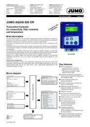
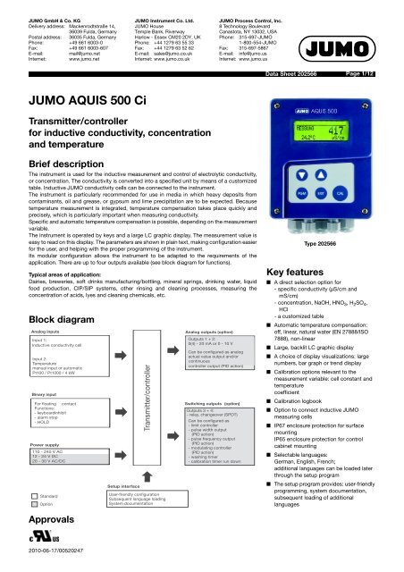
<strong>JUMO</strong> GmbH & Co. KGDelivery address: Mackenrodtstraße 14,36039 Fulda, GermanyPostal address: 36035 Fulda, GermanyPhone: +49 661 6003-0Fax: +49 661 6003-607E-mail:mail@jumo.netInternet: www.jumo.net<strong>JUMO</strong> Instrument Co. Ltd.<strong>JUMO</strong> HouseTemple Bank, RiverwayHarlow - Essex CM20 2DY, UKPhone: +44 1279 63 55 33Fax: +44 1279 63 52 62E-mail: sales@jumo.co.ukInternet: www.jumo.co.uk<strong>JUMO</strong> Process Control, Inc.8 Technology BoulevardCanastota, NY 13032, USAPhone: 315-697-<strong>JUMO</strong>1-800-554-<strong>JUMO</strong>Fax: 315-697-5867E-mail: info@jumo.usInternet: www.jumo.usData Sheet 202566Page 1/12<strong>JUMO</strong> <strong>AQUIS</strong> <strong>500</strong> <strong>Ci</strong>Transmitter/controllerfor inductive conductivity, concentrationand temperatureBrief descriptionThe instrument is used for the inductive measurement and control of electrolytic conductivity,or concentration. The conductivity is converted into a specified unit by means of a customizedtable. Inductive <strong>JUMO</strong> conductivity cells can be connected to the instrument.The instrument is particularly recommended for use in media in which heavy deposits fromcontaminants, oil and grease, or gypsum and lime precipitation are to be expected. Becausetemperature measurement is integrated, temperature compensation takes place quickly andprecisely, which is particularly important when measuring conductivity.Specific and automatic temperature compensation is possible, depending on the measurementvariable.The instrument is operated by keys and a large LC graphic display. The measurement value iseasy to read on this display. The parameters are shown in plain text, making configuration easierfor the user, and helping with the proper programming of the instrument.Its modular configuration allows the instrument to be adapted to the requirements of theapplication. There are up to four outputs available (see block diagram for functions).Typical areas of application:Dairies, breweries, soft drinks manufacturing/bottling, mineral springs, drinking water, liquidfood production, CIP/SIP systems, other rinsing and cleaning processes, measuring theconcentration of acids, lyes and cleaning chemicals, etc.Block diagramAnalog inputsInput 1:Inductive conductivity cellInput 2:Temperaturemanual input or automaticPt100 / Pt1000 / 4 kWBinary inputFor floating contactFunctions:- keyboardinhibit- alarm stop- HOLDPower supply110 - 240 V AC12 - 24 V DC20 - 30 V AC/DCStandardOptionApprovalsSetup interfaceTransmitter/controllerUser-friendly configurationSubsequent language loadingSystem documentationAnalog outputs (option)Outputs 1 + 2:0(4) - 20 mA or 0 - 10 VCan be configured as analogactual value output and/orcontinuouscontroller output (PID action)Switching outputs (option)Outputs 3 + 4:- relay, changeover (SPDT)Can be configured as- limit controller- pulse width output(PID action)- pulse frequency output(PID action)- modulating controller(PID action)- washing timer- calibration timer run downType 202566Key features■ A direct selection option for- specific conductivity (µS/cm andmS/cm)- concentration, NaOH, HNO 3 , H 2 SO 4 ,HCl- a customized table■ Automatic temperature compensation:off, linear, natural water (EN 27888/ISO7888), non-linear■ Large, backlit LC graphic display■ A choice of display visualizations: largenumbers, bar graph or trend display■ Calibration options relevant to themeasurement variable: cell constant andtemperaturecoefficient■ Calibration logbook■ Option to connect inductive <strong>JUMO</strong>measuring cells■ IP67 enclosure protection for surfacemountingIP65 enclosure protection for controlcabinet mounting■ Selectable languages:German, English, French;additional languages can be loaded laterthrough the setup program■ The setup program provides: user-friendlyprogramming, system documentation,subsequent loading of additionallanguages2010-06-17/00520247
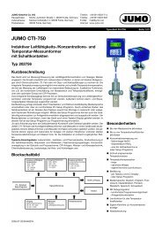
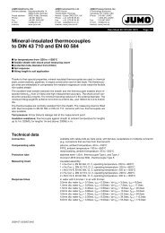
<strong>JUMO</strong> GmbH & Co. KGDelivery address: Mackenrodtstraße 14,36039 Fulda, GermanyPostal address: 36035 Fulda, GermanyPhone: +49 661 6003-0Fax: +49 661 6003-607E-mail:mail@jumo.netInternet: www.jumo.net<strong>JUMO</strong> Instrument Co. Ltd.<strong>JUMO</strong> HouseTemple Bank, RiverwayHarlow - Essex CM20 2DY, UKPhone: +44 1279 63 55 33Fax: +44 1279 63 52 62E-mail: sales@jumo.co.ukInternet: www.jumo.co.uk<strong>JUMO</strong> Process Control, Inc.8 Technology BoulevardCanastota, NY 13032, USAPhone: 315-697-<strong>JUMO</strong>1-800-554-<strong>JUMO</strong>Fax: 315-697-5867E-mail: info@jumo.usInternet: www.jumo.usData Sheet 202566Page 2/12Functional descriptionThe instrument is designed for on-site use. Arobust housing protects the electronics andelectrical connections against aggressiveenvironmental conditions (IP67). As analternative, the instrument can also beinstalled in a panel; the front then has IP65enclosure protection. Easily installed screwconnectors are used for electrical connection.A ventilation screw with a PTFE membraneprevents condensation buildup.TransmitterThe transmitter receives the measurementsignal from the inductive measuring cells ofthe <strong>JUMO</strong> tecLINE <strong>Ci</strong> series, see data sheet202941.With the inductive measurement method,acquisition of specific conductivity is largelymaintenance-free, even in the most difficult ofmedium conditions. Unlike the conductivemeasurement method, there are practically noproblems such as electrode breakdown andpolarization.By acquiring the temperature of the samplemedium, the instrument can automaticallyperform temperature compensation.Components of the measurementchain(1) (2)(1) <strong>JUMO</strong> tecLine <strong>Ci</strong>, inductiveconductivity and temperature sensor(2) Cable(<strong>JUMO</strong> tecLine <strong>Ci</strong> component)(3) <strong>JUMO</strong> <strong>AQUIS</strong> <strong>500</strong> <strong>Ci</strong>, transmitter/controller for conductivity,concentration and temperatureDisplays and controls(1)Switching output 1 or 2 is active(2)Binary input 1 is triggered(3)Keyboard inhibited2010-06-17/00520247(3)(1) (2) (3) (4) (5)(6) (7) (8) (9)(4)Alarm has been activated(5)Instrument is in manual mode(6)Instrument status(7)Medium temperature(8)Main measurement(9)Unit of main measurementThe user can specify what is to appear inpositions (7) and (8) of the display:- No display- Corrected or uncorrected measurement- Temperature- Output level 1 or 2- Setpoint 1 or 2OperationTo make programming and operation easy, allparameters are clearly assigned to levels anddisplayed in plain text. Operation is protectedby a code word. Operation can be adapted onan individual basis because parameters canbe generally enabled or assigned to theprotected area.A setup program for the PC is available as amore convenient configuration option, ratherthan using the instrument keyboard.Display modesThree display modes are available:Large numbersHere the measurements are displayed innumbers, as usual.Trend displayHere the numerical value is supplemented bya symbol to indicate the direction and speedof change for the measurement.This can be very useful when the controller isbeing optimized, for example.from left to right:fast, medium and slow rise,steady,slow, medium and fast fall.Bar graphIn this display mode, it only takes a glance toascertain the range for the currentmeasurement.Any scale can be used for the bar graph.Function modesElectrolytic conductivityµS/cm or mS/cm are the units used fordisplay and control.Concentration measurementCaustic sodaNaOH0 - 12 % by weightNaOH25 - 50 % by weightNitric acidHNO 3 0 - 25 % by weightHNO 3 36 - 82 % by weightSulphuric acidH 2 SO 4 0-28% by weightH 2 SO 4 36 - 85 % weightH 2 SO 4 92 - 99 % by weightHydrochloric acidHCl 0 - 18 % by weightHCl 22 - 44 % by weightCustomized tableIn this mode, the input value (specificconductivity) can be displayed in accordancewith a table (max. 20 value pairs). Thisfunction can be used to implement simpleconcentration measurements, for example.Table values can only be entered using theoptional setup program.CalibrationCell constantBecause of manufacturing constraints, thecell constant of a conductivity measuring cellmay differ slightly from its nominal value.Wear or the accumulation of deposits duringoperation can also cause the cell constant tochange. This changes the output signal fromthe measuring cell. With this instrument, theuser has the opportunity to compensate fordeviations in the nominal value of the cellconstant by manual input, or by automaticcalibration of the relevant cell constant.Installation factorThis parameter can be used to compensatefor unfavorable sensor mounting conditions.Temperature coefficientThe conductivity of virtually all solutions istemperature dependent. To ensure correctmeasurement therefore, both the temperatureand the temperature coefficient a [%/C] of themeasurement solution must be known. Thetemperature can either be measuredautomatically with a Pt 100 or Pt 1000temperature probe, or the user must set thetemperature by hand.The temperature coefficient can beautomatically determined by the instrument,or it can be entered by hand.Calibration logbookThe last five successful calibrations can beaccessed in the calibration logbook. Thisallows the ageing of the connected sensor to
<strong>JUMO</strong> GmbH & Co. KGDelivery address: Mackenrodtstraße 14,36039 Fulda, GermanyPostal address: 36035 Fulda, GermanyPhone: +49 661 6003-0Fax: +49 661 6003-607E-mail:mail@jumo.netInternet: www.jumo.net<strong>JUMO</strong> Instrument Co. Ltd.<strong>JUMO</strong> HouseTemple Bank, RiverwayHarlow - Essex CM20 2DY, UKPhone: +44 1279 63 55 33Fax: +44 1279 63 52 62E-mail: sales@jumo.co.ukInternet: www.jumo.co.uk<strong>JUMO</strong> Process Control, Inc.8 Technology BoulevardCanastota, NY 13032, USAPhone: 315-697-<strong>JUMO</strong>1-800-554-<strong>JUMO</strong>Fax: 315-697-5867E-mail: info@jumo.usInternet: www.jumo.usData Sheet 202566Page 3/12be assessed.Control functionsFunctions that are configured by parameterscan be assigned to the relay. P, PI, PD andPID structures can be freely programmed ascontrol functions.Alarm function AF 8 right (min.)ONHyStCalibration timerThe calibration timer indicates (on request) arequired routine calibration. The calibrationtimer is activated by entering the number ofdays that must expire before there is ascheduled re-calibration (specified by thesystem or the operator).Min/max value memoryThis memory records the minimum andmaximum input quantities that occur. Thisinformation can be used, for example, toassess whether the design of the connectedsensor is suitable for the values that actuallyoccur.Binary inputThe following functions can be accessedthrough the binary input:- Key inhibit activationWhen this function is activated, operationis no longer possible via the keyboard.- "HOLD" mode activationWhen this function is activated, theoutputs (analog and relay) adopt thestates previously defined.- Alarm suppression (controller alarm only)With this function, it is possible totemporarily deactivate alarm generationvia the relevantly configured relay.The predefined function is activated using afloating contact (such as a relay) to bridge therelevant terminals.Analog outputsThere are up to 2 analog outputs available.The following functions can be selected:Relay outputsTwo relay changeover contacts are availablefor the main measurement variable and/or thetemperature.The following functions can be programmed:- Switching direction(min/max)- Limit controller(switch-on/switch-off delay, hysteresis)- Pulse width output(see Control functions)- Pulse frequency output(see Control functions)- Modulating function(see Control functions)- Alarm functions(switch-on/switch-off delay, hysteresis)- Pulse controlsWith this function, the output brieflyswitches on when the switching point isreached and then switches off again- Alarm- Sensor/range error- Behavior in the event of an alarm,underrange or overrange measurement,calibration and "HOLD"Contact functionsAlarm function AF 7 left (max.)ONALHyStMeasurement valueOutput Analog process value output Continuous controllerMain variable Temperaturemain value1 X - X2 - X XWith the analog process value output, the range start and end values are freely selectable.The response of the outputs to over/underrange, alarm and calibration is freely programmable.Simulation function: The analog process value outputs can be freely set in the manual ("Hand")mode.Application: "Dry run" start-up of the plant, troubleshooting, servicing.ALMeasurement valueWindow alarm function AF 1 leftONHyStALWindow alarm function AF 2 rightONHyStALPulse contactTriggering condition longer than pulsedurationTriggeringOnconditionOffTimePulseOncontactOffTimePulse durationPulse contactTriggering condition shorter than pulsedurationTriggeringconditionOffPulsecontactOffPulse width controller(output active with X > W and controlwwOnOnPulse durationMeasurement valueMeasurement valueTimeTime2010-06-17/00520247
<strong>JUMO</strong> GmbH & Co. KGDelivery address: Mackenrodtstraße 14,36039 Fulda, GermanyPostal address: 36035 Fulda, GermanyPhone: +49 661 6003-0Fax: +49 661 6003-607E-mail:mail@jumo.netInternet: www.jumo.net<strong>JUMO</strong> Instrument Co. Ltd.<strong>JUMO</strong> HouseTemple Bank, RiverwayHarlow - Essex CM20 2DY, UKPhone: +44 1279 63 55 33Fax: +44 1279 63 52 62E-mail: sales@jumo.co.ukInternet: www.jumo.co.uk<strong>JUMO</strong> Process Control, Inc.8 Technology BoulevardCanastota, NY 13032, USAPhone: 315-697-<strong>JUMO</strong>1-800-554-<strong>JUMO</strong>Fax: 315-697-5867E-mail: info@jumo.usInternet: www.jumo.usData Sheet 202566Page 4/12structure P)Output level y100%90%50%10%0%Proportional band X P0 X - W 1X PSetpoint W90%Switching period50% 50%t On t Off10%90%If actual value X exceeds setpoint W, the Pcontroller will control in proportion to thecontrol deviation. When the proportional bandis exceeded, the controller operates with anoutput level of 100% (100% clock ratio).Pulse frequency controller(output active with X > W and controlstructure P)Output level y100%50%0%Proportional band X P0 X - W 1X PSetpoint Wno pulses10%Actual value Xmaximum pulse frequency50% pulse frequencyActual value XIf actual value X exceeds setpoint W, the Pcontroller will control in proportion to thecontrol deviation. When the proportional bandis exceeded, the controller operates with anoutput level of 100% (maximum switchingfrequency).Technical dataMain input conductivityMeasuring rangeAccuracy 10.000 - 1.000 mS/cm1.01 - <strong>500</strong> mS/cm501 - 2000 mS/cmOperating modeConcentration measurementNaOH caustic solutionHNO 3H 2 SO 4HCLnitric acidsulphuric acidhydrochloric acidOperating modeCustomized table0000 - 9999 µS/cm0.000 - 9.999 mS/cm0.00 - 99.99 mS/cm0.0 - 999.9 mS/cm0 - 2000 mS/cm1.5% of the measuring range1% of the measuring range1.5% of the measuring rangeRange 1:Range 2:Range 1:Range 2:Range 1:Range 2:Range 3:Range 1:Range 2:0 - 12 % by weight20 - 50 % by weight0 - 25 % by weight36 - 82 % by weight0 - 28 % by weight36 - 85 % by weight92 - 99 % by weight0 - 18 % by weight22 - 44 % by weightThe compensated conductivity is converted to a newdisplay value by means of a table. The table can containas many as 29 value pairs.The display unit can also be adapted.Process sequence:Uncompensated conductivity > Temperaturecompensation > Linearization with table > Display value.1 Temperature error at <strong>JUMO</strong> <strong>AQUIS</strong> <strong>500</strong> <strong>Ci</strong> with inductive conductivity probe<strong>JUMO</strong> tecLINE <strong>Ci</strong>. Deviation of 22 °C relative to the output signal end value 0(4) - 20 mA and0-10V.Secondary input temperaturePt100/Pt1000Measuring rangeAccuracyAmbient temperature errorNTC / PTCMeasuring rangeAccuracyAmbient temperature errorTemperature compensationLinearTC () setting rangeTemperature rangeNatural water (ISO 7888)TC () setting rangeTemperature range-50 to 250 °C 0.5 °C0.05 %/10 °Cmax. 4 kTable input with up to 20 value pairs via setup program 0.3 °C (dependent on interpolation points)0.05 %/10 °C0 to 5.5 %/C0(-10) to 100 °Cn/a0-36°CReference temperature adjustable: 15 - 30 °Cpreset to 25 °C (standard)2010-06-17/00520247
<strong>JUMO</strong> GmbH & Co. KGDelivery address: Mackenrodtstraße 14,36039 Fulda, GermanyPostal address: 36035 Fulda, GermanyPhone: +49 661 6003-0Fax: +49 661 6003-607E-mail:mail@jumo.netInternet: www.jumo.net<strong>JUMO</strong> Instrument Co. Ltd.<strong>JUMO</strong> HouseTemple Bank, RiverwayHarlow - Essex CM20 2DY, UKPhone: +44 1279 63 55 33Fax: +44 1279 63 52 62E-mail: sales@jumo.co.ukInternet: www.jumo.co.uk<strong>JUMO</strong> Process Control, Inc.8 Technology BoulevardCanastota, NY 13032, USAPhone: 315-697-<strong>JUMO</strong>1-800-554-<strong>JUMO</strong>Fax: 315-697-5867E-mail: info@jumo.usInternet: www.jumo.usData Sheet 202566Page 5/12Measuring circuit monitoringConductivity inputOverrangeShort circuitBroken leadTemperature inputOverrange/underrangeShort circuitCell constantAdjustment range 1Adjustment range 2Setting range of therelative cell constantBinary inputyesdependent on rangedependent on rangeyesyes4-6[1/cm]6-8[1/cm]80 - 120%Installation factor 80 - 120%ActivationFunctionby floating contactkey inhibitHOLDalarm suppressionControllerController typeController structureA/D converterSampling timealarm functions, limit controllers, pulse width controllers, pulse frequency controllers,modulating controllers, continuous controllersP / PI / PD / PIDdynamic resolution up to 14 bits<strong>500</strong> msAnalog outputs (max. 2)Output type Signal range Accuracy Temperature error Permissibleload resistanceCurrent signal 0/4 - 20 mA 0.25% 0.08%/10 °C <strong>500</strong> Voltage signal 0 - 10 V 0.25% 0.08%/10 °C <strong>500</strong> The analog outputs respond in accordance with NAMUR recommendation NE43.The analog outputs are electrically isolated, 30 V AC / 50 V DC.Switching outputs (max. two (SPDT) changeovers)Rated loadContact life3 A/250 VAC (resistive load)>2x10 5 operations at rated loadSetup interfaceInterface for configuring the instrument with the available setup program option(for instrument configuration only).2010-06-17/00520247
<strong>JUMO</strong> GmbH & Co. KGDelivery address: Mackenrodtstraße 14,36039 Fulda, GermanyPostal address: 36035 Fulda, GermanyPhone: +49 661 6003-0Fax: +49 661 6003-607E-mail:mail@jumo.netInternet: www.jumo.net<strong>JUMO</strong> Instrument Co. Ltd.<strong>JUMO</strong> HouseTemple Bank, RiverwayHarlow - Essex CM20 2DY, UKPhone: +44 1279 63 55 33Fax: +44 1279 63 52 62E-mail: sales@jumo.co.ukInternet: www.jumo.co.uk<strong>JUMO</strong> Process Control, Inc.8 Technology BoulevardCanastota, NY 13032, USAPhone: 315-697-<strong>JUMO</strong>1-800-554-<strong>JUMO</strong>Fax: 315-697-5867E-mail: info@jumo.usInternet: www.jumo.usData Sheet 202566Page 6/12Electrical dataPower supply110 - 240 V AC; -15/+10%; 48 - 63 Hz20 - 30 V AC/DC; 48 - 63 Hz12 - 24 V DC +/-15% (permissible only for connection to SELV/PELV circuits)Power consumptionapprox. 14 VAElectrical safety EN 61 010, Part 1overvoltage category III 1 , pollution degree 2Data backupEEPROMElectrical connectionPower supply, relay outputs,sensor inputsAnalog outputsInductive conductivity sensorPluggable screw terminals, conductor cross-section max. 2.5 mm 2Pluggable screw terminals, conductor cross-section max. 1.5 mm 2M12 connection1 Not valid for power supply 30, 12 - 24 V DC.DisplayGraphic LC displayBacklighting120 x 32 pixelsProgrammable:- off- on for 60 seconds during operationHousingMaterialPA (polyamide)Cable entryCable glands, max. 2 x M16 and 2 x M12FeatureVenting element to prevent condensationAmbient temperature range -10to50°C(the specified accuracy is adheredto in this range)Operating temperature range(instrument operational)Storage temperature rangeClimatic ratingEnclosure protectionto EN 60529-15to65°C-30to70°CRel. humidity 90% annual mean, no condensation(based on EN 60721 3-3 3K3)Surface-mounted housing:IP67Control cabinet mounting:at front IP65, at rear IP20Vibration resistant to EN 60068-2-6WeightSurface-mounted housing:approx. 900 gControl cabinet mounting:approx. 480 gDimensions See dimensioned drawings on page 102010-06-17/00520247
<strong>JUMO</strong> GmbH & Co. KGDelivery address: Mackenrodtstraße 14,36039 Fulda, GermanyPostal address: 36035 Fulda, GermanyPhone: +49 661 6003-0Fax: +49 661 6003-607E-mail:mail@jumo.netInternet: www.jumo.net<strong>JUMO</strong> Instrument Co. Ltd.<strong>JUMO</strong> HouseTemple Bank, RiverwayHarlow - Essex CM20 2DY, UKPhone: +44 1279 63 55 33Fax: +44 1279 63 52 62E-mail: sales@jumo.co.ukInternet: www.jumo.co.uk<strong>JUMO</strong> Process Control, Inc.8 Technology BoulevardCanastota, NY 13032, USAPhone: 315-697-<strong>JUMO</strong>1-800-554-<strong>JUMO</strong>Fax: 315-697-5867E-mail: info@jumo.usInternet: www.jumo.usData Sheet 202566Page 7/12Electrical connectionThe <strong>JUMO</strong> <strong>AQUIS</strong> <strong>500</strong> <strong>Ci</strong> power supply is connected at therow 1 terminals.The row 2 terminals are factory-wired forconnecting a <strong>JUMO</strong> tecLINE Lf <strong>Ci</strong> inductive conductivitycell.Row 1N L1(L-) (L+)34 5 6 7 8 9 10Row 21 2 3 4 5 6 7 8 9 10 11 1213 14 15 16Connection Terminal RowInputsPower supply for transmitter/controllerPower supply (23): 110 - 240 V AC, + 10% / -15%, 48 - 63 HzPower supply (25): 20 - 30 V AC/DC, 48 - 63 HzPower supply (30): 12 - 24 V DC, ± 15%1 N (L-)2 L1 (L+)1NC 3Do not change this wiring!Only <strong>JUMO</strong> tecLINE Lf <strong>Ci</strong> inductive conductivity cells must be operatedat the M12 connector, seedata sheet 202941!Resistance thermometer in 2-wire circuit 8ϑ891097168524391234567892Resistance thermometer in 3-wire circuit 989ϑ8101010Binary input 111112122010-06-17/00520247
<strong>JUMO</strong> GmbH & Co. KGDelivery address: Mackenrodtstraße 14,36039 Fulda, GermanyPostal address: 36035 Fulda, GermanyPhone: +49 661 6003-0Fax: +49 661 6003-607E-mail:mail@jumo.netInternet: www.jumo.net<strong>JUMO</strong> Instrument Co. Ltd.<strong>JUMO</strong> HouseTemple Bank, RiverwayHarlow - Essex CM20 2DY, UKPhone: +44 1279 63 55 33Fax: +44 1279 63 52 62E-mail: sales@jumo.co.ukInternet: www.jumo.co.uk<strong>JUMO</strong> Process Control, Inc.8 Technology BoulevardCanastota, NY 13032, USAPhone: 315-697-<strong>JUMO</strong>1-800-554-<strong>JUMO</strong>Fax: 315-697-5867E-mail: info@jumo.usInternet: www.jumo.usData Sheet 202566Page 8/12Connection Terminal RowOutputsAnalog output 10 - 20 mA and 20 - 0 mA or 4 - 20 mA and 20 - 4 mAor0 - 10 V and 10 - 0 V (electrically isolated)Analog output 20 - 20 mA and 20 - 0 mA or 4 - 20 mA and 20 - 4 mAor0 - 10 V and 10 - 0 V (electrically isolated)Switching output K1 (floating)54+ 13- 14+ 15- 164 pole5 NC6 NO26NC 7Switching output K2 (floating)988 pole9 NC10 NO1102010-06-17/00520247
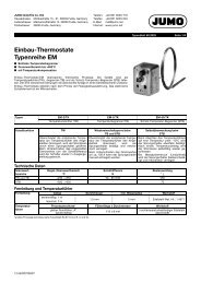
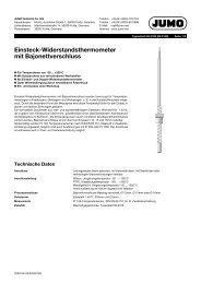
ø 10<strong>JUMO</strong> GmbH & Co. KGDelivery address: Mackenrodtstraße 14,36039 Fulda, GermanyPostal address: 36035 Fulda, GermanyPhone: +49 661 6003-0Fax: +49 661 6003-607E-mail:mail@jumo.netInternet: www.jumo.net<strong>JUMO</strong> Instrument Co. Ltd.<strong>JUMO</strong> HouseTemple Bank, RiverwayHarlow - Essex CM20 2DY, UKPhone: +44 1279 63 55 33Fax: +44 1279 63 52 62E-mail: sales@jumo.co.ukInternet: www.jumo.co.uk<strong>JUMO</strong> Process Control, Inc.8 Technology BoulevardCanastota, NY 13032, USAPhone: 315-697-<strong>JUMO</strong>1-800-554-<strong>JUMO</strong>Fax: 315-697-5867E-mail: info@jumo.usInternet: www.jumo.usData Sheet 202566Page 9/12Dimensions306014913477 942316114094120Panel mounting/drilling diagram44.2100.5ø 4.5120.5Note:1. Attach template to panel.2. Drill holes ( ø4.5 mm and ø10 mm)3. Cut out the section within the markinglines.4. DeburrTo ensure enclosure protection (see datasheet), the panel must be sufficientlystable.121.6108.6Note:The drilling template is shown actual size inoperating manual B 202566.0.2010-06-17/00520247
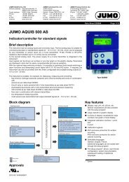
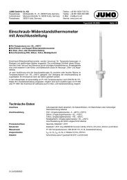
<strong>JUMO</strong> GmbH & Co. KGDelivery address: Mackenrodtstraße 14,36039 Fulda, GermanyPostal address: 36035 Fulda, GermanyPhone: +49 661 6003-0Fax: +49 661 6003-607E-mail:mail@jumo.netInternet: www.jumo.net<strong>JUMO</strong> Instrument Co. Ltd.<strong>JUMO</strong> HouseTemple Bank, RiverwayHarlow - Essex CM20 2DY, UKPhone: +44 1279 63 55 33Fax: +44 1279 63 52 62E-mail: sales@jumo.co.ukInternet: www.jumo.co.uk<strong>JUMO</strong> Process Control, Inc.8 Technology BoulevardCanastota, NY 13032, USAPhone: 315-697-<strong>JUMO</strong>1-800-554-<strong>JUMO</strong>Fax: 315-697-5867E-mail: info@jumo.usInternet: www.jumo.usData Sheet 202566Page 10/12Accessories<strong>JUMO</strong> <strong>AQUIS</strong> <strong>500</strong>Weather protection roofPipe installation set(clamping range ø 30 - 50 mm)Universal jointadjustablewith clamping leverapprox. 1<strong>500</strong>approx. 1700Chain(approx. 3 m)ArmadjustableSuspension fitting1Support pillarBase clamp1 The suspension fitting comprises a holder for suspension fitting 20/00453191 (see Accessories) and a measuring cell with a suitable fitting (seeT202922, for example):2010-06-17/00520247
<strong>JUMO</strong> GmbH & Co. KGDelivery address: Mackenrodtstraße 14,36039 Fulda, GermanyPostal address: 36035 Fulda, GermanyPhone: +49 661 6003-0Fax: +49 661 6003-607E-mail:mail@jumo.netInternet: www.jumo.net<strong>JUMO</strong> Instrument Co. Ltd.<strong>JUMO</strong> HouseTemple Bank, RiverwayHarlow - Essex CM20 2DY, UKPhone: +44 1279 63 55 33Fax: +44 1279 63 52 62E-mail: sales@jumo.co.ukInternet: www.jumo.co.uk<strong>JUMO</strong> Process Control, Inc.8 Technology BoulevardCanastota, NY 13032, USAPhone: 315-697-<strong>JUMO</strong>1-800-554-<strong>JUMO</strong>Fax: 315-697-5867E-mail: info@jumo.usInternet: www.jumo.usData Sheet 202566Page 11/12Order details:<strong>JUMO</strong> <strong>AQUIS</strong> <strong>500</strong> <strong>Ci</strong>(1) Basic type202566<strong>JUMO</strong> <strong>AQUIS</strong> <strong>500</strong> <strong>Ci</strong>transmitter/controller for inductive conductivity, concentration and temperature(2) Basic type extension10 for panel mounting20 in surface-mounted housing(3) Output 1 (for main value or continuous controller)000 no output888 analog output 0(4) - 20 mA and 0 - 10 V(4) Output 2 (for temperature or continuous controller)000 no output888 analog output 0(4) - 20 mA and 0 - 10 V(5) Output 3000 no output310 relay with changeover contact(6) Output 4000 no output310 relay with changeover contact(7) Power supply23 110 - 240 V AC, + 10% / -15%, 48 - 63 Hz25 20 - 30 V AC/DC, 48 - 63 Hz30 12 - 24 V DC, ± 15%(8) Extra codes000 none(1) (2) (3) (4) (5) (6) (7) (8)Order code / - - - - - / , ...Order example 202566 / 20 - 888 - 000 - 310 - 000 - 23 / 0002010-06-17/00520247
<strong>JUMO</strong> GmbH & Co. KGDelivery address: Mackenrodtstraße 14,36039 Fulda, GermanyPostal address: 36035 Fulda, GermanyPhone: +49 661 6003-0Fax: +49 661 6003-607E-mail:mail@jumo.netInternet: www.jumo.net<strong>JUMO</strong> Instrument Co. Ltd.<strong>JUMO</strong> HouseTemple Bank, RiverwayHarlow - Essex CM20 2DY, UKPhone: +44 1279 63 55 33Fax: +44 1279 63 52 62E-mail: sales@jumo.co.ukInternet: www.jumo.co.uk<strong>JUMO</strong> Process Control, Inc.8 Technology BoulevardCanastota, NY 13032, USAPhone: 315-697-<strong>JUMO</strong>1-800-554-<strong>JUMO</strong>Fax: 315-697-5867E-mail: info@jumo.usInternet: www.jumo.usData Sheet 202566Page 12/12Stock versions (delivery 3 days after receipt of order)TypeSalesNo.202566/20-888-888-310-310-23/000 20/00542691Production version (delivery 10 days after receipt of order)Type202566/20-888-000-310-000-23/000 20/00550657202566/20-888-888-310-310-25/000 20/00548188Accessories (delivery 10 days after receipt of order)TypeSalesNo.Protective roof for <strong>JUMO</strong> <strong>AQUIS</strong> <strong>500</strong> 1 20/00398161Pipe installation set for <strong>JUMO</strong> <strong>AQUIS</strong> <strong>500</strong> 2 20/00483664DIN rail installation set for <strong>JUMO</strong> <strong>AQUIS</strong> <strong>500</strong> 3 20/00477842Support pillar with base clamp, arm and chain 20/00398163Holder for suspension fitting 20/00453191Back panel set 202560/65/66/68 20/00506351PC setup software 20/00483602PC interface cable including USB/TTL converter and two adapters (USB connecting cable) 70/00456352Calibration adapter for inductive conductivity measurement, type 202711/21 20/00543395NoteThe following are required for the initial commissioning of the sensor and transmitter/controller or when replacing components:- transmitter/controller e. g. <strong>JUMO</strong> <strong>AQUIS</strong> <strong>500</strong> <strong>Ci</strong>, data sheet 202566- <strong>JUMO</strong> tecLine <strong>Ci</strong> inductive conductivity and temperature sensor, data sheet 202941- Calibration adapter for inductive conductivity measurement, type 202711/21, data sheet 2027111 The pipe installation set is needed for fitting the protective roof.2 With the pipe installation set, the <strong>JUMO</strong> <strong>AQUIS</strong> <strong>500</strong> can be attached to a pipe (e. g. a support pillar or a railing).3 With the DIN rail installation set, the <strong>JUMO</strong> <strong>AQUIS</strong> <strong>500</strong> can be attached to a 35 mm x 7.5 mm DIN rail as per EN 60715 A.1.2010-06-17/00520247