JUMO AQUIS 500 CR
JUMO AQUIS 500 CR
JUMO AQUIS 500 CR
- No tags were found...

You also want an ePaper? Increase the reach of your titles
YUMPU automatically turns print PDFs into web optimized ePapers that Google loves.
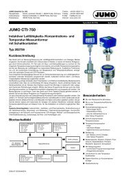
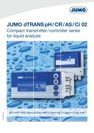
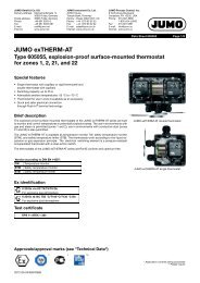
<strong>JUMO</strong> GmbH & Co. KGDelivery address:Mackenrodtstraße 14,36039 Fulda, GermanyPostal address: 36035 Fulda, GermanyPhone: +49 661 6003-0Fax: +49 661 6003-607e-mail: mail@jumo.netInternet: www.jumo.net<strong>JUMO</strong> Instrument Co. Ltd.<strong>JUMO</strong> HouseTemple Bank, RiverwayHarlow, Essex CM 20 2TT, UKPhone: +44 1279 635533Fax: +44 1279 635262e-mail: sales@jumo.co.ukInternet: www.jumo.co.uk<strong>JUMO</strong> Process Control, Inc.8 Technology BoulevardCanastota, NY 13031, USAPhone: 315-697-<strong>JUMO</strong>1-800-554-<strong>JUMO</strong>Fax: 315-697-5867e-mail: info@jumo.usInternet: www.jumo.usData Sheet 20.2565Page 1/12<strong>JUMO</strong> <strong>AQUIS</strong> <strong>500</strong> <strong>CR</strong>Transmitter/Controllerfor conductivity, TDS, resistivityand temperatureCompliant withUSPBrief descriptionThe instrument is used for the conductive measurement/control of electrolytic conductivity,resistivity or the TDS value. In addition, the <strong>JUMO</strong> <strong>AQUIS</strong> <strong>500</strong> <strong>CR</strong> also offers the possibility ofshowing the measured conductivity according to a customer-specific table.Conductive two-electrode cells as well as four-electrode cells can be connected to theinstrument.Temperature serves as the second input variable, measured by a Pt100/1000 probe. Dependingon the measured variable, it is therefore possible to implement specific, automatic temperaturecompensation.The instrument is operated using keys and a large LC graphics display on which themeasurements are clearly legible. The plain-text presentation of the parameters makes it easierfor the user to configure the instrument, and also helps in programming it correctly.Thanks to its modular design, the instrument can be perfectly matched to the particularapplication requirement. Up to four outputs are available (see the block diagram for thefunctions).Typical areas of applicationUniversally applicable in water and wastewater engineering, service/process water andwastewater, drinking water and well/surface water, pure and high-purity water as well as forpharmaceutical water (e.g. as per USP, Ph.Eur., WFI), water quality measurements, TDSmeasurements (ppm or mg/l).Block diagram2 analog inputsInput 1:Conductivity / resistivityInput 2:Temperaturemanual input or automaticPt100 / Pt1000 / 4 kΩ1 binary inputFor floating contactFunctions:- key inhibit- alarm stop- HOLDSupply voltage110—230 V AC12—24 V DC20—30 V AC/DCstandardoptionSetup interfaceTransmitter/controllerUser-friendly configurationReloading of languagesPlant documentationAnalog outputs (option)Output 1 + 2:0(4)—20 mA or 0—10 VConfigurable as analog processvalue output and/or continuouscontroller output (PID action)Switching outputs (option)Outputs 3 + 4:- relay, changeover (SPDT)Configurable as- limit controller- pulse width output(PID action)- pulse frequency output(PID action)- modulating controller(PID action)- USP contact- "Purified water" contactas per Ph.Eur.- calibration timer run downType 202565Key features■ Direct changeover to- conductivity (µS/cm or mS/cm)- resistivity (kΩ x cm or MΩ x cm)- TDS measurement (ppm or mg/l)- customer-specific table■ Automatic temperature compensation:off (e.g. USP), linear, ASTM, natural water(EN 27888/ISO 7888)■ Large LC graphics display withbackground lighting■ Choice of display: large numbers, bargraph or trend display■ Calibration options according tomeasured variable: cell constant andtemperature coefficient■ Calibration logbook■ Two-electrode cells (as standard) orfour-electrode cells can be connected■ Pollution detection can be activated■ Auto-range operation■ IP67 enclosure protection(in wall-mounting housing)IP65 enclosure protection(for panel mounting)■ Language changeover:German, English, French;further languages can be loaded throughthe setup program■ Using the setup program: user-friendlyprogramming, plant documentation,additional languages can be loaded10.07/00477047
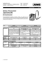
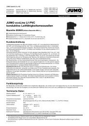
<strong>JUMO</strong> GmbH & Co. KGDelivery address:Mackenrodtstraße 14,36039 Fulda, GermanyPostal address: 36035 Fulda, GermanyPhone: +49 661 6003-0Fax: +49 661 6003-607e-mail: mail@jumo.netInternet: www.jumo.net<strong>JUMO</strong> Instrument Co. Ltd.<strong>JUMO</strong> HouseTemple Bank, RiverwayHarlow, Essex CM 20 2TT, UKPhone: +44 1279 635533Fax: +44 1279 635262e-mail: sales@jumo.co.ukInternet: www.jumo.co.uk<strong>JUMO</strong> Process Control, Inc.8 Technology BoulevardCanastota, NY 13031, USAPhone: 315-697-<strong>JUMO</strong>1-800-554-<strong>JUMO</strong>Fax: 315-697-5867e-mail: info@jumo.usInternet: www.jumo.usData Sheet 20.2565Page 2/12Functional descriptionThe instrument is designed for use on site. Arugged housing protects the electronics andthe electrical connections from corrosiveenvironmental conditions (IP67). As analternative, the instrument can also beinstalled in a control panel, and is thenprotected to IP65 on the front. The electricalconnection is made by easy-to-fit pluggablescrew terminals.TransmitterTwo-electrode cells (standard) as well as fourelectrodecells can be used for measurement.Two-electrode cells can be connected, in theusual increments for cell constants (K=0.01;0.1; 1.0; 3.0 and 10.0). Thanks to the widelyadjustable relative cell constant, it is alsopossible to connect sensors with different cellconstants (e.g. K=0.2).In the case of the 4-electrode cells, the valuesK=0.5 and 1.0 have been predefined for thecell constant. Here too, the instrument can bematched to sensors with different cellconstants (e.g. K=0.4).The instrument can perform automatictemperature compensation, by acquiring thetemperature of the sample solution.Displays and controls(1) (2) (3) (4) (5)(6) (7) (8) (9)(1) Switching output 1 or 2 is active(2) Binary input 1 is actuated(3) Keypad is inhibited(4) Alarm has been activated(5) Instrument is in manual mode(6) Instrument status(7) Temperature of medium(8) Principal measurement(9) Unit of principal measurementThe user can define what is to be shown inpositions (7) and (8) of the display:- no display- compensated or uncompensatedmeasurement- temperature- output level 1 or 2- setpoint 1 or 2OperationFor easy programming and operation, allparameters are arranged in clearly structuredlevels and shown in plain text. Operation isprotected by a code word. This facilitatesindividual adaptation of the operation, sinceparameters can be generally enabled orspecifically assigned to the protected area.As an alternative to configuration from thekeys, the instrument can also be configuredthrough the convenient setup program for PC(option).Display modesThree display modes are available:Large numbersIn this display mode, the measurements areshown in digits, as usual.Trend displayThe numerical value is supplemented by asymbol which indicates the change directionand change speed of the measurement.This can, for instance, be very useful duringcontroller optimization.from left to right:fast, medium and slow rise, stable,slow, medium and fast fall.Bar graphThis display mode allows the user to see at aglance in which region the measurement is atpresent.The bar graph can be freely scaled.Function modesElectrolytic conductivityDisplay/control, unit µS/cm or mS/cm.Resistivity (high-purity water)Display/control, unit kΩ x cm or MΩ x cm.TDSDisplay/control with ppm for the unit.In this mode, the specific TDS factor can beentered in addition.Customer-specific tableIn this mode, the input value (conductivity orresistivity) can be displayed in accordancewith a table (up to 20 value pairs). Thanks tothis function, it is possible to implementsimple concentration measurements, forexample. The values in the table can only beentered through the optional setup program.CalibrationCell constantBecause of manufacturing tolerances, the cellconstant of a conductivity cell may deviateslightly from its nominal value. In addition, thecell constant may change during operation(due to deposits or wear, for example). Thisresults in a change of the output signal fromthe cell. The instrument provides the user withthe possibility of compensating any deviationfrom the nominal value of the cell constant bymanual entry or automatic calibration of therelative cell constant. A manual entry is used,for instance, for calibration during high-puritywater measurement.Temperature coefficientThe conductivity of almost all solutionsdepends on the temperature. To ensurecorrect measurement, it is thereforenecessary to know both the temperature andthe temperature coefficient [%/°C] of thesample solution. The temperature can eitherbe measured automatically, with a Pt100 orPt1000 temperature probe, or it has to be setmanually by the user.The temperature coefficient can beautomatically determined by the instrument,or it can be entered manually.Calibration logbookThe five most recent successful calibrationscan be called up in the calibration logbook.This makes it possible to evaluate the ageingof the sensor that is connected.Calibration timerThe calibration timer indicates (if required)when the next routine calibration is due. Thecalibration timer is activated by entering anumber of days, after which recalibration hasto be carried out (plant or operatorrequirement).MIN / MAX value memoryThis memory acquires the minimum ormaximum input variables that have occurred.This information serves, for example, todecide whether the sensor that is connectedis suited to the values that are actuallypresent.10.07/00477047
<strong>JUMO</strong> GmbH & Co. KGDelivery address:Mackenrodtstraße 14,36039 Fulda, GermanyPostal address: 36035 Fulda, GermanyPhone: +49 661 6003-0Fax: +49 661 6003-607e-mail: mail@jumo.netInternet: www.jumo.net<strong>JUMO</strong> Instrument Co. Ltd.<strong>JUMO</strong> HouseTemple Bank, RiverwayHarlow, Essex CM 20 2TT, UKPhone: +44 1279 635533Fax: +44 1279 635262e-mail: sales@jumo.co.ukInternet: www.jumo.co.uk<strong>JUMO</strong> Process Control, Inc.8 Technology BoulevardCanastota, NY 13031, USAPhone: 315-697-<strong>JUMO</strong>1-800-554-<strong>JUMO</strong>Fax: 315-697-5867e-mail: info@jumo.usInternet: www.jumo.usData Sheet 20.2565Page 3/12Detection of depositsDeposit detection can be activated for 4-electrode cells.During normal operation, it can happen thatdeposits form on electrodes. This has theresult that a lower concentration is displayedthan actually present. With activated “depositdetection” function, the instrument tells youwhen the cell needs to be serviced.Auto-rangeFor some processes, the availability of twomeasuring ranges is advantageous, forinstance for rinsing or regenerationprocesses.What is usually required here, is the preciseacquisition of a low conductivity. Rinsing orregeneration, however, involves a muchhigher conductivity, which could lead to anout-of-range condition (error). This situation isnot just unsatisfactory, but may even bedangerous. Thanks to the auto-rangefunction, two measuring ranges can bedetermined. The instrument then switchesbetween them in a defined manner.Binary inputThe following functions can be activatedthrough the binary input:- Activate key inhibitWhen this function has been activated,operation from the keys is no longerpossible.- Activate HOLD modeAfter activating this function, the outputs(analog and relay) adopt the states thathave previously been defined.- Alarm suppression (controller alarm only)This function temporarily deactivates thealarm generation via the relay (has to beconfigured accordingly).Linking the corresponding terminals bymeans of a floating contact (e. g. relay) willactivate the pre-defined function.Analog OutputsControl functionsThe relays can have functions assigned thatare configured via parameters. The controlfunction is freely programmable as P, PI, PD orPID action.Analog outputsUp to two analog outputs are available,configurable as analog process value outputor continuous controller. The “analog processvalue output” function can be assigned to theprinciple measurement variable or to thetemperature. The “continuous controller”function can only be assigned to the principlemeasurement variable. Both functions can becombined.With the analog process value output, therange start and end values are freelyselectable.The response of the outputs to over/underrange, HOLD and calibration is freelyprogrammable.Simulation function:The analog process value outputs can befreely set in the manual (“Hand”) mode.Application:“Dry-run” start-up of the plant, troubleshooting,servicingRelay outputsTwo relay changeover contacts are availablefor the principle measurement variable and/ortemperature.The following functions can be programmed:- Switching direction(min/max)- Limit controller(pull-in/drop-out delay, hysteresis)- Pulse width output(see control functions)- Pulse frequency output(see control functions)There are up to 2 analog outputs available.The following functions can be selected:Output Analog process value output Continuous controllerPrinciple measurementvariablePrinciple measurementTemperaturevariable1 X - X2 - X XWith the analog process value output, the range start and end values are freely selectable.The response of the outputs to over/underrange, alarm and calibration is freely programmable.Simulation function:The analog process value outputs can be freely set in the manual ("Hand") mode.Application:"Dry run" start-up of the plant, troubleshooting, servicing.- Modulating controller function(see control functions)- Limit comparators(pull-in/drop-out delay, hysteresis)- Pulse functionThe output switches on briefly whenreaching the switching point and then offagain.- Alarm- Sensor or range error- Response to alarm, over/underrange,calibration and HOLDContact functionsMAX limit comparatorOffMIN limit comparatorOnAlarm window 1OffHysteresisAlarm window 2OffHysteresisOnLimitSetpointHysteresisLimitSetpointDistanceLimitSetpointHysteresisDistanceLimitSetpointOffOnpHpHOnpHpH10.07/00477047
<strong>JUMO</strong> GmbH & Co. KGDelivery address:Mackenrodtstraße 14,36039 Fulda, GermanyPostal address: 36035 Fulda, GermanyPhone: +49 661 6003-0Fax: +49 661 6003-607e-mail: mail@jumo.netInternet: www.jumo.net<strong>JUMO</strong> Instrument Co. Ltd.<strong>JUMO</strong> HouseTemple Bank, RiverwayHarlow, Essex CM 20 2TT, UKPhone: +44 1279 635533Fax: +44 1279 635262e-mail: sales@jumo.co.ukInternet: www.jumo.co.uk<strong>JUMO</strong> Process Control, Inc.8 Technology BoulevardCanastota, NY 13031, USAPhone: 315-697-<strong>JUMO</strong>1-800-554-<strong>JUMO</strong>Fax: 315-697-5867e-mail: info@jumo.usInternet: www.jumo.usData Sheet 20.2565Page 4/12Pulse contactTrigger condition longer than pulsedurationTriggerOnconditionOffTimePulseOncontactOffTimePulse durationPulse contactTrigger condition shorter than pulsedurationTriggerconditionOffPulsecontactOffOnOnPulse durationTimeTimePulse width controller(output is active with X > W and P action)Output level y100%90%50%10%0%Proportional band X P0 X - W 1X PSetpoint W90%Switching period50% 50%t Ont Off10%90%10%Process value XIf the process value X exceeds the setpoint W,the P controller will control proportionally tothe control deviation. On going outside theproportional band, the controller operateswith an output level of 100% (100% dutycycle).Pulse frequency controller(output is active with X > W and P action)Output level y100%50%0%Proportional band X P0 X - W 1X PSetpoint WMaximum pulse frequency50% of pulse frequencyNo pulses Process value XIf the process value X exceeds the setpoint W,the P controller will control proportionally tothe control deviation. On going outside theproportional band, the controller operateswith an output level of 100% (maximumswitching frequency).Measuring ranges / cell constantsThis state-of-the art instrument offers a far wider dynamic range on the input side than can be managed physically or chemically by theconductivity cells. For this reason, the range must be matched to the operating range of the cell.Examples of ranges for combinationwith 2-electrode cellsCell constant (K)Recommended/practical measuring span(depending on the conductivity cell)0.01 1/cm 0.05 µS/cm — 20 µs/cm0.1 1/cm 1 µS/cm — 1000 µs/cm1.0 1/cm 0.01 mS/cm — 100 ms/cm3.0 1/cm 0.1 mS/cm — 30 ms/cm10.0 1/cm 0.1 mS/cm — 200 ms/cmExampleA measurement is to be carried out in the 10 µS/cm to <strong>500</strong> µS/cm range. A conductivity cell with the cell constant K = 0.1 1/cm is chosen.The unit µS/cm without a decimal place is configured on the instrument.Combination with 4-electrode cells and 2-electrode cellshaving cell constants that deviate from the above graduationThis requires taking a closer look at the instrument technology and considering both the uncompensated and the temperature-compensatedmeasuring span.The uncompensated measuring span of the instrument is calculated according to the formula:Measuring span = 0.1µs/cm x cell constant (K) to 2<strong>500</strong> mS x cell constant (K).After taking account of the temperature compensation range, the following compensated measuring span (approx.) will remain:Measuring span = 0.1µs/cm x cell constant (K) to 1250 mS x cell constant (K).Cell constant (K)Measuring span covered by instrument(temperature-compensated)0.01 0.001 µS/cm — 1.25 ms/cm0.1 0.01µS/cm—12.5ms/cm1.0 0.1 µS/cm — 125 ms/cm3.0 0.3 µS/cm — 375 ms/cm10.0 0.1 mS/cm — 1250 ms/cm10.07/00477047
<strong>JUMO</strong> GmbH & Co. KGDelivery address:Mackenrodtstraße 14,36039 Fulda, GermanyPostal address: 36035 Fulda, GermanyPhone: +49 661 6003-0Fax: +49 661 6003-607e-mail: mail@jumo.netInternet: www.jumo.net<strong>JUMO</strong> Instrument Co. Ltd.<strong>JUMO</strong> HouseTemple Bank, RiverwayHarlow, Essex CM 20 2TT, UKPhone: +44 1279 635533Fax: +44 1279 635262e-mail: sales@jumo.co.ukInternet: www.jumo.co.uk<strong>JUMO</strong> Process Control, Inc.8 Technology BoulevardCanastota, NY 13031, USAPhone: 315-697-<strong>JUMO</strong>1-800-554-<strong>JUMO</strong>Fax: 315-697-5867e-mail: info@jumo.usInternet: www.jumo.usData Sheet 20.2565Page 5/12It is assumed that the measuring span of the instrument is always larger than the recommended or practically usable range of the conductivity cell.The smaller range (instrument or conductivity cell) determines the maximum range that can be used.ExampleWhich span can the instrument cover with a predefined cell constant?The predefined cell constant is K=0.4The span of the instrument = 0.1 µS/cm x 0.4 1/cm to 1250 mS/cm x 0.4 1/cm ➝ 0.04 µS/cm — <strong>500</strong> mS/cmTechnical dataInputsPrincipal input Indication range Accuracy Temperature errorµS/cm 0.000 — 9.99900.00 — 99.99000.0 — 999.90000 — 9999mS/cm 0.000 — 9.99900.00 — 99.99000.0 — 999.90000 — 9999kΩ x cm 0.000 — 9.99900.00 — 99.99000.0 — 999.90000 — 9999MΩ x cm 0.000 — 9.99900.00 — 99.99000.0 — 999.90000 — 9999Temperature compensationMeasuring circuit monitoring≤ 0.6% of range + 0.3 µS x cellconstant (K)≤ 0.6% of range + 0.3 µS x cellconstant (K)≤ 0.6% of range + 0.3 µS x cellconstant (K)≤ 0.6% of range + 0.3 µS x cellconstant (K)0.2%/10°C0.2%/10°C0.2%/10°C0.2%/10°CSecondary input Measuring range Accuracy Temperature errorTemperature-50 to 250°C 1 ≤ 0.5°C 0.05%/10°CPt100/1000(automatic detection)TemperatureNTC/PTCmax. 4 kOhmInput via tablewith 20 value pairs,through setup program≤ 0.3% 20.05%/10°CType of compensation Range 3Linear 0 — 8%/°C -10 to 160°CASTM D1125 - 95 (high-purity water) 0 to 100°CNatural water (ISO 7888) 0 to 36°<strong>CR</strong>eference temperatureadjustable from 15 to 30°C; preset to 25°C (standard)Inputs Over/underrange Short-circuit Cable breakConductivity yes depending on range depending on rangeTemperature yes yes yes1 Switchable to °F.2 Depending on interpolation points.3 Please note operating temperature range of sensor.10.07/00477047
<strong>JUMO</strong> GmbH & Co. KGDelivery address:Mackenrodtstraße 14,36039 Fulda, GermanyPostal address: 36035 Fulda, GermanyPhone: +49 661 6003-0Fax: +49 661 6003-607e-mail: mail@jumo.netInternet: www.jumo.net<strong>JUMO</strong> Instrument Co. Ltd.<strong>JUMO</strong> HouseTemple Bank, RiverwayHarlow, Essex CM 20 2TT, UKPhone: +44 1279 635533Fax: +44 1279 635262e-mail: sales@jumo.co.ukInternet: www.jumo.co.uk<strong>JUMO</strong> Process Control, Inc.8 Technology BoulevardCanastota, NY 13031, USAPhone: 315-697-<strong>JUMO</strong>1-800-554-<strong>JUMO</strong>Fax: 315-697-5867e-mail: info@jumo.usInternet: www.jumo.usData Sheet 20.2565Page 6/122-electrode systemsCell constant[1/cm]0.014-electrode systemsSetting range ofrelative cell constantResulting usablerange [1/cm]0.002 — 0.050.1 0.02 — 0.51.0 20 — <strong>500</strong>%0.2 — 53.0 0.6 — 1510.0 2.0 — 50Cell constant[1/cm]0.5Setting range ofrelative cell constantResulting usablerange [1/cm]0.1 — 0.7520 — 150%1.0 0.2 — 1.5Binary inputActivationFunctionControllerController typeController actionA/D converterSampling timethrough floating contactkey inhibitHOLDalarm suppressionlimit comparators, limit controller, pulse width controller, pulse frequency controller, modulating controller,continuous controllerP / PI / PD / PIDdynamic resolution up to 14-bit<strong>500</strong> msecAnalog outputs (one or two)Output mode Signal range Accuracy Temperature error Permissibleload resistanceCurrent signal 0/4 — 20 mA ≤ 0.25% 0.08%/10 °C ≤ <strong>500</strong>ΩVoltage signal 0 – 10 V ≤ 0.25% 0.08%/10 °C ≥ <strong>500</strong> ΩThe analog outputs respond in accordance with the recommendation as per NAMUR NE43.They are electrically isolated, 30 V AC / 50 V DC.Switching outputs (two changeover (SPDT) max.)Rated loadContact lifeSetup interface3 A/250 VAC (resistive load)>2x10 5 operations at rated loadInterface for configuring the instrument through the optionally available setup program (for instrument configuration only).Electrical dataSupply voltage110 — 230 V AC; -15/+10%; 48 — 63 Hz20—30V AC/DC; 48—63Hz12 — 24 V DC +/-15% (permissible only for connection to SELV/PELV circuits)Power consumptionapprox. 11 VAElectrical safety EN 61 010, Part 1overvoltage category III 1 , pollution degree 21 Not valid with protective extra-low voltage (PELV) of power supply variant 12 — 24 V DC.10.07/00477047
<strong>JUMO</strong> GmbH & Co. KGDelivery address:Mackenrodtstraße 14,36039 Fulda, GermanyPostal address: 36035 Fulda, GermanyPhone: +49 661 6003-0Fax: +49 661 6003-607e-mail: mail@jumo.netInternet: www.jumo.net<strong>JUMO</strong> Instrument Co. Ltd.<strong>JUMO</strong> HouseTemple Bank, RiverwayHarlow, Essex CM 20 2TT, UKPhone: +44 1279 635533Fax: +44 1279 635262e-mail: sales@jumo.co.ukInternet: www.jumo.co.uk<strong>JUMO</strong> Process Control, Inc.8 Technology BoulevardCanastota, NY 13031, USAPhone: 315-697-<strong>JUMO</strong>1-800-554-<strong>JUMO</strong>Fax: 315-697-5867e-mail: info@jumo.usInternet: www.jumo.usData Sheet 20.2565Page 7/12Data backupElectrical connectionDisplayGraphics LC displayBackground lightingEEPROMpluggable screw terminalsconductor cross-section up to 2.5 mm 2 (supply, relay outputs, sensor inputs)conductor cross-section up to 1.5 mm 2 (analog outputs)120 x 32 pixelsprogrammable:- off- on for 60 seconds during operationHousingMaterialPA (polyamide)Cable entrycable glands, 3xM16 and 2xM12 max.Special featureventing device to prevent condensationAmbient temperature range -10 to 50°C(the specified accuracy is adheredto within this range)Operating temperature range(instrument is operational)Standard accessoriesCable glandsInternal mounting materialOperating Instructions-15 to 65°CStorage temperature range -30 to 70°CClimatic conditionsrel. humidity ≤ 90% annual mean, no condensation(following EN 60721 3-3 3K3)Enclosure protectionas per EN 60529in wall-mounting housing: IP67for panel mounting: IP65 front, IP20 rearVibration strength as per EN 60068-2-6Weight wall-mounting housing: approx. 900 gfor panel mounting: approx. 480 gDimensions see dimensioned drawings on page 10.10.07/00477047
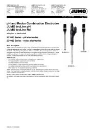
<strong>JUMO</strong> GmbH & Co. KGDelivery address:Mackenrodtstraße 14,36039 Fulda, GermanyPostal address: 36035 Fulda, GermanyPhone: +49 661 6003-0Fax: +49 661 6003-607e-mail: mail@jumo.netInternet: www.jumo.net<strong>JUMO</strong> Instrument Co. Ltd.<strong>JUMO</strong> HouseTemple Bank, RiverwayHarlow, Essex CM 20 2TT, UKPhone: +44 1279 635533Fax: +44 1279 635262e-mail: sales@jumo.co.ukInternet: www.jumo.co.uk<strong>JUMO</strong> Process Control, Inc.8 Technology BoulevardCanastota, NY 13031, USAPhone: 315-697-<strong>JUMO</strong>1-800-554-<strong>JUMO</strong>Fax: 315-697-5867e-mail: info@jumo.usInternet: www.jumo.usData Sheet 20.2565Page 8/12Electrical connectionThe electrical connection for the “wall-mounting housing”version can be made easily, after opening the unit.Clamp (screen)The connection cable between sensor and transmitter mustbe a screened cable with a diameter of 8 mm max.The instrument contains a guide plate for an optimized cablerouting.The sensor cables (incorporating strain relief) are run to thepluggable screw terminals where they are connected withoutusing any solder.Row 1Row 2Connection Terminal RowSupply for transmitter/controlleras standard:1 N (L-)Supply voltage (25):20 — 30 V AC/DC2 L1 (L+)Supply voltage (23):110 — 230 V ACSupply voltage (30):12 — 24 V DC1NC 310.07/00477047
<strong>JUMO</strong> GmbH & Co. KGDelivery address:Mackenrodtstraße 14,36039 Fulda, GermanyPostal address: 36035 Fulda, GermanyPhone: +49 661 6003-0Fax: +49 661 6003-607e-mail: mail@jumo.netInternet: www.jumo.net<strong>JUMO</strong> Instrument Co. Ltd.<strong>JUMO</strong> HouseTemple Bank, RiverwayHarlow, Essex CM 20 2TT, UKPhone: +44 1279 635533Fax: +44 1279 635262e-mail: sales@jumo.co.ukInternet: www.jumo.co.uk<strong>JUMO</strong> Process Control, Inc.8 Technology BoulevardCanastota, NY 13031, USAPhone: 315-697-<strong>JUMO</strong>1-800-554-<strong>JUMO</strong>Fax: 315-697-5867e-mail: info@jumo.usInternet: www.jumo.usData Sheet 20.2565Page 9/12Connection Terminal RowInputsConductivity cell (2-electrode system)Terminals 1+2 and 3+4 are linked in the instrument;2-wire cable routed to the head of the conductivity cell.For concentric cells, terminal 1 is connected to the outer electrode.1231234Conductivity cell (2-electrode system)Wiring for the highest accuracy;4-wire cable routed to the head of the conductivity cell.For concentric cells, terminal 1 is connected to the outer electrode.Conductivity cell (4-electrode system)1 - outer electrode 1 (I hi)2 - inner electrode 1 (U hi)3 - inner electrode 2 (U lo)4 - outer electrode 2 (I lo)NC 567RTD in 2-wire circuit 8ϑ89109412341234123412342RTD in 3-wire circuit 989ϑ8101010Binary input 11111212OutputsAnalog output 10 — 20 mA or 20 — 0 mA or 4 — 20 mA or 20 — 4 mAor0 — 10 V or 10 — 0 V(electrically isolated)Analog output 20 — 20 mA or 20 — 0 mA or 4 — 20 mA or 20 — 4 mAor0 — 10 V or 10 — 0 V(electrically isolated)Switching output K1(floating)54+ 13- 14+ 15- 164 common5 break (SPST-NC)6 make (SPST-NO)26NC 7Switching output K2(floating)988 common9 break (SPST-NC)10 make (SPST-NO)11010.07/00477047
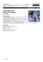
ø10ø4.5<strong>JUMO</strong> GmbH & Co. KGDelivery address:Mackenrodtstraße 14,36039 Fulda, GermanyPostal address: 36035 Fulda, GermanyPhone: +49 661 6003-0Fax: +49 661 6003-607e-mail: mail@jumo.netInternet: www.jumo.net<strong>JUMO</strong> Instrument Co. Ltd.<strong>JUMO</strong> HouseTemple Bank, RiverwayHarlow, Essex CM 20 2TT, UKPhone: +44 1279 635533Fax: +44 1279 635262e-mail: sales@jumo.co.ukInternet: www.jumo.co.uk<strong>JUMO</strong> Process Control, Inc.8 Technology BoulevardCanastota, NY 13031, USAPhone: 315-697-<strong>JUMO</strong>1-800-554-<strong>JUMO</strong>Fax: 315-697-5867e-mail: info@jumo.usInternet: www.jumo.usData Sheet 20.2565Page 10/12Dimensions306014913477 942316114094120Panel-mounting/drilling diagram44.2100.5120.5Note:1. Fix template to panel2. Drill holes ( 4.5 mm and 10 mm dia.)3. Cut out the panel inside themarked lines.4. Debur121.6Note:The drilling template is shown in its actual sizein the Operating Instructions B 20.2565.0.To ensure the protection rating(see data sheet), the panel mustbe sufficiently stable.108.610.07/00477047
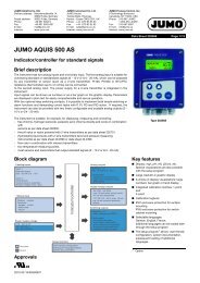
<strong>JUMO</strong> GmbH & Co. KGDelivery address:Mackenrodtstraße 14,36039 Fulda, GermanyPostal address: 36035 Fulda, GermanyPhone: +49 661 6003-0Fax: +49 661 6003-607e-mail: mail@jumo.netInternet: www.jumo.net<strong>JUMO</strong> Instrument Co. Ltd.<strong>JUMO</strong> HouseTemple Bank, RiverwayHarlow, Essex CM 20 2TT, UKPhone: +44 1279 635533Fax: +44 1279 635262e-mail: sales@jumo.co.ukInternet: www.jumo.co.uk<strong>JUMO</strong> Process Control, Inc.8 Technology BoulevardCanastota, NY 13031, USAPhone: 315-697-<strong>JUMO</strong>1-800-554-<strong>JUMO</strong>Fax: 315-697-5867e-mail: info@jumo.usInternet: www.jumo.usData Sheet 20.2565Page 11/12Accessories<strong>JUMO</strong> <strong>AQUIS</strong> <strong>500</strong>Weather protection coverPole-mounting kitUniversal joint(adjustable)with clamping leverapprox. 1<strong>500</strong>approx. 1700ChainArm(adjustable)Suspended fittingSupport pillarPedestal base1 The suspended fitting consists of a fixing 20/00453191 (see accessories) and a cell with a suitable fitting (see data sheet 20.2922, for example).10.07/00477047
<strong>JUMO</strong> GmbH & Co. KGDelivery address:Mackenrodtstraße 14,36039 Fulda, GermanyPostal address: 36035 Fulda, GermanyPhone: +49 661 6003-0Fax: +49 661 6003-607e-mail: mail@jumo.netInternet: www.jumo.net<strong>JUMO</strong> Instrument Co. Ltd.<strong>JUMO</strong> HouseTemple Bank, RiverwayHarlow, Essex CM 20 2TT, UKPhone: +44 1279 635533Fax: +44 1279 635262e-mail: sales@jumo.co.ukInternet: www.jumo.co.uk<strong>JUMO</strong> Process Control, Inc.8 Technology BoulevardCanastota, NY 13031, USAPhone: 315-697-<strong>JUMO</strong>1-800-554-<strong>JUMO</strong>Fax: 315-697-5867e-mail: info@jumo.usInternet: www.jumo.usData Sheet 20.2565Page 12/12Order details:<strong>JUMO</strong> <strong>AQUIS</strong> <strong>500</strong> <strong>CR</strong>(1) Basic type202565<strong>JUMO</strong> <strong>AQUIS</strong> <strong>500</strong> <strong>CR</strong>Transmitter/controller for conductivity, TDS, resistivity and temperature(2) Basic type extensions10 for panel mounting20 in wall-mounting housing(3) Output 1 (for principle measurement variable or continuous controller)000 no output888 analog output 0(4) — 20 mA or 0 — 10 V(4) Output 2 (for principle measurement variable or continuous controller)000 no output888 analog output 0(4) — 20 mA or 0 — 10 V(5) Output 3000 no output310 relay with changeover (SPDT) contact(6) Output 4000 no output310 relay with changeover (SPDT) contact(7) Supply voltage23 110 — 230 V AC + 10% / -15%, 48 — 63 Hz25 20 — 30 V AC/DC, 48 — 63 Hz 130 12 — 24 V DC ± 15% 1(8) Extra codes000 none(1) (2) (3) (4) (5) (6) (7) (8)Order code / - - - / - / , ... 2Order example 202565 / 20 - 888 - 000 - 310 / 000 - 23 / 000Stock items (shipment: 3 working days after receipt of order)TypeSales No.202565/20-888-888-310-310-23/000 20/00480055202565/20-888-000-310-000-23/000 20/00480054Production items (shipment: 10 days after receipt of order)TypeSales No.202565/10-888-888-310-310-23/000 20/00480053202565/10-888-000-310-000-23/000 20/00480052202565/10-888-888-310-310-25/000 1 20/00484566Accessories (shipment: 10 days after receipt of order)TypeSales No.Protection cover for <strong>JUMO</strong> <strong>AQUIS</strong> <strong>500</strong> 3 20/00398161Pole-mounting kit for <strong>JUMO</strong> <strong>AQUIS</strong> <strong>500</strong> 4 20/00483664Support pillar with pedestal base, arm and chain 20/00398163PC setup software 20/00483602PC interface cable including USB/TTL converter and adapter (USB connection cable) 70/00456352Fixing for suspended fitting 20/004531911 Can be supplied from about the 3rd quarter of 2007.2 List extra codes in sequence, separated by commas.3 The pole-mounting kit is needed for mounting the protection cover.4 Using the pole-mounting kit, the <strong>JUMO</strong> <strong>AQUIS</strong> <strong>500</strong> can be fitted to a pole (e. g. support pillar or railing).10.07/00477047