JUMO AQUIS 500 CR
JUMO AQUIS 500 CR
JUMO AQUIS 500 CR
- No tags were found...

You also want an ePaper? Increase the reach of your titles
YUMPU automatically turns print PDFs into web optimized ePapers that Google loves.
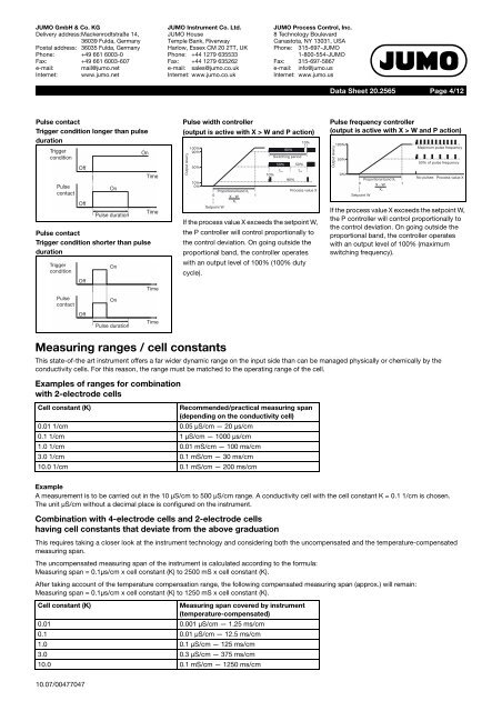
<strong>JUMO</strong> GmbH & Co. KGDelivery address:Mackenrodtstraße 14,36039 Fulda, GermanyPostal address: 36035 Fulda, GermanyPhone: +49 661 6003-0Fax: +49 661 6003-607e-mail: mail@jumo.netInternet: www.jumo.net<strong>JUMO</strong> Instrument Co. Ltd.<strong>JUMO</strong> HouseTemple Bank, RiverwayHarlow, Essex CM 20 2TT, UKPhone: +44 1279 635533Fax: +44 1279 635262e-mail: sales@jumo.co.ukInternet: www.jumo.co.uk<strong>JUMO</strong> Process Control, Inc.8 Technology BoulevardCanastota, NY 13031, USAPhone: 315-697-<strong>JUMO</strong>1-800-554-<strong>JUMO</strong>Fax: 315-697-5867e-mail: info@jumo.usInternet: www.jumo.usData Sheet 20.2565Page 4/12Pulse contactTrigger condition longer than pulsedurationTriggerOnconditionOffTimePulseOncontactOffTimePulse durationPulse contactTrigger condition shorter than pulsedurationTriggerconditionOffPulsecontactOffOnOnPulse durationTimeTimePulse width controller(output is active with X > W and P action)Output level y100%90%50%10%0%Proportional band X P0 X - W 1X PSetpoint W90%Switching period50% 50%t Ont Off10%90%10%Process value XIf the process value X exceeds the setpoint W,the P controller will control proportionally tothe control deviation. On going outside theproportional band, the controller operateswith an output level of 100% (100% dutycycle).Pulse frequency controller(output is active with X > W and P action)Output level y100%50%0%Proportional band X P0 X - W 1X PSetpoint WMaximum pulse frequency50% of pulse frequencyNo pulses Process value XIf the process value X exceeds the setpoint W,the P controller will control proportionally tothe control deviation. On going outside theproportional band, the controller operateswith an output level of 100% (maximumswitching frequency).Measuring ranges / cell constantsThis state-of-the art instrument offers a far wider dynamic range on the input side than can be managed physically or chemically by theconductivity cells. For this reason, the range must be matched to the operating range of the cell.Examples of ranges for combinationwith 2-electrode cellsCell constant (K)Recommended/practical measuring span(depending on the conductivity cell)0.01 1/cm 0.05 µS/cm — 20 µs/cm0.1 1/cm 1 µS/cm — 1000 µs/cm1.0 1/cm 0.01 mS/cm — 100 ms/cm3.0 1/cm 0.1 mS/cm — 30 ms/cm10.0 1/cm 0.1 mS/cm — 200 ms/cmExampleA measurement is to be carried out in the 10 µS/cm to <strong>500</strong> µS/cm range. A conductivity cell with the cell constant K = 0.1 1/cm is chosen.The unit µS/cm without a decimal place is configured on the instrument.Combination with 4-electrode cells and 2-electrode cellshaving cell constants that deviate from the above graduationThis requires taking a closer look at the instrument technology and considering both the uncompensated and the temperature-compensatedmeasuring span.The uncompensated measuring span of the instrument is calculated according to the formula:Measuring span = 0.1µs/cm x cell constant (K) to 2<strong>500</strong> mS x cell constant (K).After taking account of the temperature compensation range, the following compensated measuring span (approx.) will remain:Measuring span = 0.1µs/cm x cell constant (K) to 1250 mS x cell constant (K).Cell constant (K)Measuring span covered by instrument(temperature-compensated)0.01 0.001 µS/cm — 1.25 ms/cm0.1 0.01µS/cm—12.5ms/cm1.0 0.1 µS/cm — 125 ms/cm3.0 0.3 µS/cm — 375 ms/cm10.0 0.1 mS/cm — 1250 ms/cm10.07/00477047